ma24108a, true-rms, 10 mhz to 8 ghz ma24118a, true-rms, 10 mhz to … · microwave usb power...
TRANSCRIPT

Product Brochure
Microwave USB Power SensorsMA24108A, True-RMS, 10 MHz to 8 GHz MA24118A, True-RMS, 10 MHz to 18 GHzLow Cost, Compact, and Highly Accurate Power Sensors for RF and Microwave Applications
2
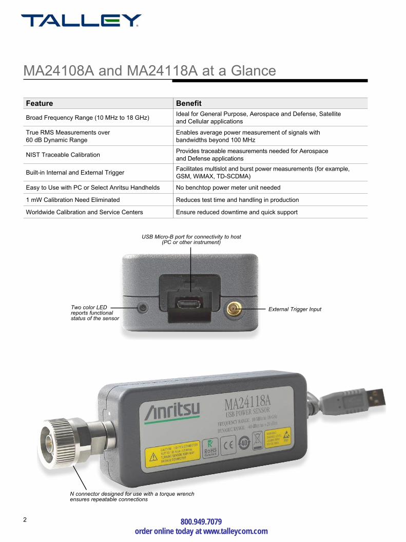
MA24108A and MA24118A at a Glance
Feature Benefit
Broad Frequency Range (10 MHz to 18 GHz)Ideal for General Purpose, Aerospace and Defense, Satellite and Cellular applications
True RMS Measurements over 60 dB Dynamic Range
Enables average power measurement of signals with bandwidths beyond 100 MHz
NIST Traceable CalibrationProvides traceable measurements needed for Aerospace and Defense applications
Built-in Internal and External TriggerFacilitates multislot and burst power measurements (for example, GSM, WiMAX, TD-SCDMA)
Easy to Use with PC or Select Anritsu Handhelds No benchtop power meter unit needed
1 mW Calibration Need Eliminated Reduces test time and handling in production
Worldwide Calibration and Service Centers Ensure reduced downtime and quick support
Two color LED reports functional status of the sensor
External Trigger Input
USB Micro-B port for connectivity to host (PC or other instrument)
N connector designed for use with a torque wrench ensures repeatable connections
800.949.7079 order online today at www.talleycom.com

3
Dual-path Architecture provides True-RMS Measurements
The MA24108A and MA24118A USB Power sensors are designed to provide accurate average power measurements from 10 MHz to 18 GHz over 60 dB of dynamic range. The sensors employ a “dual path” architecture that provides (similar to thermal sensor) True-RMS measurements over the entire frequency and dynamic range, enabling users to make highly accurate average power measurements for CW, multi-tone, and digitally modulated signals up to 18 GHz.
Highly accurate modulation measurements are facilitated by keeping the diode detectors in the “square law region” and by choosing the output of the appropriate detector path. A built-in attenuator provides excellent SWR performance, thus minimizing mismatch error. The sensor has built-in external trigger (in addition to a software based internal trigger) circuitry with an MCX connector interface to receive trigger from external stimuli for reliable analysis of very complex timeslot configurations. The presence of a micro-controller along with signal conditioning circuitry, ADC, and power supply in the sensor makes it a complete miniature power meter. All calibration factors, as well as linearity and temperature corrections, are stored inside the sensor. To ensure high accuracy, the standards that are used to calibrate this sensor are directly traceable to the US National Institute of Standards and Technology (NIST), and periodic calibrations are supported by Anritsu service centers worldwide.
RF Input
USB
ExternalTriggerInput
10 dBAttenuator
DetectorB
DetectorA
Range 1
Range 2
29 dBAttenuator
6 dBSplitter
4 dBAttenuator
Preamplifier
Preamplifier
TemperatureSensor
LPF
LPF
ADC
ADC
PowerSupply
ExternalSRAM
ExternalFlash
Microcontroller
MA24108A and MA24118A Block Diagram

4
Optimized for Production
The MA24108A and MA24118A facilitate lab quality measurement on the production floor for a fraction of cost of existing solutions enabling better test margins. Because the sensor is connected directly to the PC, no base unit is needed, saving valuable rack space. The ability of the sensor to receive external trigger from other instruments, such as signal or function generators, enables its use in complex ATE system applications. The sensor measurement speed can be optimized via features such as auto averaging and auto ranging for best accuracy and noise performance, thus making it suitable for a wide variety of ATE applications. Multiple sensors can be connected and can be controlled remotely via a single PC, allowing flexibility to match specific measurement need. A software toolkit is supplied with every sensor and contains a sample program with source code for controlling the sensor in ATE environments. The reference calibrator (50 MHz, 1 mW) typically needed by power meters has also been eliminated because the connecting USB cable transfers only digital data (corrected power), minimizing test station complexity and sensor handling, and reducing test times.
General Purpose and Defense Testing
High Accuracy for R&D use
The MA24108A and MA24118A USB power sensors are ideal for R&D of general purpose and wireless devices and systems due to their low cost, ability to measure a variety of RF and microwave waveforms, wide dynamic range, and power accuracy. Their compact size saves space by replacing traditional benchtop instruments. True-RMS power measurements of modulated signals are made effortlessly with no limits on modulation bandwidths.
Measurement linearity error referenced to an ideal thermal power sensor measurement at 2 GHz of WiMAX (green trace), CDMA2000 (red trace) and four slot GSM (black trace) signals.
Measurement linearity error referenced to an ideal thermal power sensor measurement of CW signals operating at 2 GHz (green trace), 8 GHz (red trace) and 18 GHz (black trace).
800.949.7079 order online today at www.talleycom.com

5
RF and Microwave Communication Systems Testing
Antenna measurements over long distance via LAN or Ethernet
Ideal for Field
The MA24108A and MA24118A USB power sensors provide lab performance accuracy in a rugged and compact field solution. The sensor accuracy is assured over a wide temperature range (0 ºC to 55 ºC), making it ideal for cellular base station and microwave point-to-point radio installation and maintenance applications. Field and service technicians will appreciate the small size and light weight of this standalone unit because they can carry it in their shirt pocket or laptop case. A very easy to use PC application with a large display makes operation straightforward for users with limited training. The high damage level (+33 dBm) and ESD protection provide ruggedness to this high performance sensor. Presence of DC block at the front end of the sensor protects it from RF signals carrying DC power content. Because these sensors are designed for low power requirements, laptop battery life is preserved.
LANLANEthernet Ethernet
Antenna
USB to LANConverter
MA24118A or MA24108AUSB Power Sensor
Control Room
Remote Monitoring via LAN
Because the USB cable that is connected to the sensor transfers only corrected power back to the host, a 1 mW reference calibrator is not required. However, USB data transfer capabilities limit the cable length to 5 meters, which prohibits any remote monitoring. This limitation can be overcome by installing any generic low cost USB-to-LAN hub converter (for example, a Belkin FL5009) at the measurement site along with the sensors. In this way, power monitoring can be performed across continents, if desired.

6
Compact and Powerful
Time Slot Measurements
Time Slot mode operation is generally useful when doing measurement on TDMA waveforms such as GSM/EDGE. The slot mode breaks up the measurement in time slots and calculates the average power reading for each individual slot. Similar to the scope mode, measurements are internally or externally triggered. The sensor has built- in external trigger circuitry with an MCX connector interface to receive trigger from external stimuli for reliable analysis of very complex timeslot configurations. The sensor has the ability to support up to 128 slots intervals and 300 ms total Capture Time. This feature allows entire frames of many types of communication signals to be analyzed. Similar to the scope mode, the unwanted portions in the transition from one timeslot to the next can be masked by user-definable exclusion periods.
The MA24108A and MA24118A sensors have the ability to internally trigger (acquire the trigger from signal under test) or receive an external trigger signal. The triggering capabilities of the power sensor can be exploited in the Scope and the Time Slot modes (via PowerXpert or remote programming commands) of the sensor that enable power measurements on signal bursts and within individual timeslots of TDMA systems, respectively. The sensor ADC can sample RF waveforms at 140,000 samples per second with a Capture Time of up to 300 ms. Negative trigger delay can be introduced to analyze pre-trigger waveform events. Positive trigger delay is especially useful for analysis of non-periodic waveforms.
Scope Measurements
In scope mode, the sensor is triggered internally or externally to display power measurements with respect to time. Measurement of noisy or modulated signals can be challenging because the trigger can occur at a wrong point or at a wrong edge. To provide immunity against noise and modulation effects, a noise immunity factor and trace averaging can be adjusted. A Gate and Fence feature enables measurement of the desired portion of the waveform. All points that fall within the gate are measured, and points that fall within the fence are rejected. This feature is particularly useful when measuring waveforms that contain very short duty cycle timing information that otherwise skews average power measurement.
Measurement of average power of a WiMAX burst while excluding the effects of preamble
via gate and fence feature of MA24118A using PowerXpert.
Measurement of a GSM four slot waveform with a MA24118A and PowerXpert in Time Slot mode
800.949.7079 order online today at www.talleycom.com

7
Compatibility
These power sensors can be used with a PC running Microsoft Windows® via USB. They come with PowerXpert™ application, a data analysis, and control software. A front panel display makes the PC appear like a traditional power meter. The application has abundant features, such as data logging, power versus time graph, big numerical display, and many more, that enable quick and accurate measurements.
MA24118A with MS2724B Spectrum Master
MA24118A with PC Laptop
The power sensors are also compatible with an Option-19-enabled Spectrum Master™, BTS Master™, VNA Master™, and with the MS271xB Economy Microwave Spectrum Analyzer family of instruments. The power sensor easily connects to these instruments via a USB A/micro-B cable, turning each of them into a virtual power meter that displays average power of signal under test. Users interested in making measurements in Timeslot mode and Scope mode must use a PC instead (PowerXpert or remote programming commands).
Measurement of average power in slot 4 of TD-SCDMA waveform via time gating feature of
MA24118A using PowerXpert.

8
Specifications
MA24108A MA24118A
Sensor
Frequency Range 10 MHz to 8 GHz 10 MHz to 18 GHz
Dynamic Range (CW) -40 dBm to +20 dBm
Dynamic Range (Timeslot) -40 dBm to +20 dBm
Dynamic Range (Scope) -40 dBm to +20 dBm
SWR <1.17, 10 MHz to 150 MHz <1.12, 150 MHz to 2 GHz <1.22, 2 GHz to 8 GHz
<1.17, 10 MHz to 150 MHz <1.12, 150 MHz to 2 GHz <1.22, 2 GHz to 12 GHz <1.25, 12 GHz to 18 GHz
Signal channel rise time 8 µs typical
Signal channel BW 50 kHz typical
Sampling rate 140 ks/s, typical
Measurement ranges Range 1, +20 dBm to -5 dBm typical Range 2, -5 dBm to -40 dBm typical Auto ranging between range 1 and 2
Measurement Uncertainty
Linearity <3%
Cal factor1 <1.5%
Noise2 < 8 µW, Range 1 < 40 nW, Range 2
Zero set3 < 1 µW, Range 1 < 10 nW, Range 2
Zero drift4 < 0.5 µW, Range 1 < 3 nW, Range 2
Effect of temperature < 1.4%
Effect of digital modulation5 < 0.5%, <+18 dBm < 1.4%, >+18 dBm
System
Measurand Average power
Measurement resolution6 0.01 dB max via PowerXpert, 0.001 dB max via remote command
Offset correction7 -100 dB to +150 dB
Averaging Auto, Manual
Type Moving, Repeat
Number of averages (manual)8 1 to 40,000
Auto average
Resolution9 1 dB, 0.1 dB, 0.01 dB, 0.001 dB
Source (slot # or scope data point number)
Timeslot: 1 to 128 Scope: 1 to 1024
800.949.7079 order online today at www.talleycom.com

9
Specifications
Continuous Average Mode
Duty Cycle correction 0.01% to 100%
Aperture Time 0.01 ms to 300 ms
Measurement Time10,11 N x (Capture Time x 2.5) + Td + T
com
Scope Mode
Capture Time 0.01 to 300 ms
Data points 1 to 1024
Resolution 0.007 ms, max via remote command0.01 ms, max via PowerXpert
Measurement Time11 N x (Capture Time x 3.75) +( Pn X T
dp) + T
com
Timeslot Mode
Maximum number of slots 128
Slot width 0.01 ms to 100 ms
Maximum Capture Time 300 ms (slot width x number of slots)
Resolution 0.007 ms, max via remote command 0.01 ms, max via PowerXpert
Exclusion periods
Start Exclusion 0 ms to 10 ms
End Exclusion 0 ms to 10 ms
Measurement Time11 N x (Capture Time x 3.75) +( Pn X T
dp) + T
com
Trigger
Source12 Bus, Continuous, Internal and External
Internal Trigger
Dynamic range -20 dBm to +20 dBm
Level accuracy ±0.5 dB, typical
Slope Positive or negative
Delay Range -5 ms to +10 s
Delay resolution 10 µs
External Trigger
Impedance 100 kΩ
Type TTL/CMOS
Slope Positive or negative
Delay Range -5 ms to +10 s
Delay resolution 10 µs
Positive threshold voltage 2.0 V typical
Negative threshold voltage 1.2 V typical
Hysteresis 0.8 V typical

10
Specifications
General
RF connector N male
Interface to host USB 2.0 full speed (compatible with USB 1.0 and 1.1)
Current consumption 150 mA, typical
External Trigger Input MCX (female), 12 V max
Damage levels at RF port +33 dBm CW, ±20 V DC
Size 25 mm x 45 mm x 110 mm, excluding N connector
Weight 230 g (0.51 lb)
Environmental13
Operating Temperature Range 0 ºC to 55 ºC
Storage Temperature Range –51 ºC to +71 ºC
Humidity 45% relative humidity at 55 ºC (non-condensing) 75% relative humidity at 40 ºC (non-condensing) 95% relative humidity at 30 ºC (non-condensing)
Shock 30 g half-sine, 11 ms duration
Vibration Sinusoidal: 5 Hz to 55 Hz, 3 g max. Random: 10 Hz to 500 Hz Power Spectral Density: 0.03 g2 / Hz
EMC EN 61326, EN 55011
Safety EN 61010-1
PowerXpert (PC requirements)
Processor and RAM Minimum: Equivalent to Intel® Pentium® III with 1 GB RAM or Intel® Pentium® IV with 512 MB RAM Recommended: Equivalent to Intel® Pentium® IV with 1 GB RAM
Operating System Microsoft® Windows Vista® (32-bit only), Windows XP or Windows 2000
Hard-disk free space 100 MB, minimum
Display resolution 1024 × 768, minimum
Interface USB 2.0 full speed (compatible with USB 1.0 and 1.1)
Notes:All specs are applicable after twenty minutes warm-up at room temperature unless specified otherwise.(1) Expanded uncertainty with K=2 for absolute power measurements on CW signal at 0 dBm from 10 MHz to 18 GHz.
Calibration factor uncertainty at 10 MHz is 2.3%.(2) Expanded uncertainty with K=2 after zero operation when measured with 1 average, and 20 ms aperture time for 5 minutes.
Effect of Noise can be reduced by increasing the number of averages and/or increasing the aperture time. Noise goes down as square root of number of averages and aperture time. For example with 128 averages, the Noise is 3.5 nW (40 nW divided by √128). Effect of increased aperture time is calculated in the same way.
(3) Expanded uncertainty with K=2 after zero operation when measured with 1 average, and 20 ms aperture time for 5 minutes. (4) Expanded uncertainty with K=2 after one hour warm-up and zero operation, 1 average, 20 ms aperture time, and keeping the temperature within ±1 ºC. (5) Measurement error with reference to a CW signal of equal power and frequency at 25 ºC.(6) Resolution in PowerXpert application is 2 digits after the decimal. Native resolution of the sensor is 3 digits after the decimal.(7) Offset correction feature is available only through PowerXpert application. There is no remote command for it in the sensor firmware.(8) Maximum number of averages allowed in Continuous Average mode and Timeslot mode is 40,000. In scope, the maximum number of averages
is equal to 8231936 divided by data points. (9) Averaging resolution of 0.001 dB is not available with PowerXpert application. It is defined as the place after the decimal to which the reading becomes stable.
E.g. if 0.01 is selected then the reading will typically be stable ± 0.01 dB. Please refer to the remote operation chapter in the user guide for information regarding access to this feature.
(10) Td is the delay compensation for smaller Capture Times, T
d = 0 for Capture Time > 9 ms, T
d = 3 ms for 2 ms < Capture Time < 9 ms, T
d = 5 ms
for Capture Time < 2 ms.(11) Where N is the number of repeat averages, N = 1 for moving average mode, P
n = Number of points, T
dp = 0.05 ms (Communication delay (approx)
due to each point), Tcom
= 5 ms, command processing time.(12) Bus trigger not available in PowerXpert application.(13) Tests were performed per MIL-PRF-28800F (Class 2).

11
Ordering Information
MA24108A 8 GHz USB Power SensorMA24118A 18 GHz USB Power Sensor
Available Options
Precision Coaxial Adapters
Model Frequency range Connectors
510-90 DC-3.3 GHz N (m) to 7/16 DIN (f)
510-91 DC-3.3 GHz N (f) to 7/16 DIN (f)
510-92 DC-3.3 GHz N (m) to 7/16 DIN (m)
510-93 DC-3.3 GHz N (f) to 7/16 DIN (m)
33NFNF50B DC to 18 GHz N (f) to N (f)
33NNF50B DC to 18 GHz N (m) to N (f)
33NN50B DC to 18 GHz N (m) to N (m)
34AN50 DC to 18 GHz GPC-7 to N (m)
34ANF50 DC to 18 GHz GPC-7 to N (f)
34NFK50 DC to 18 GHz N (f) to K (m)
34NFKF50 DC to 18 GHz N (m) to K (f)
34NK50 DC to 18 GHz N (m) to K (m)
34NKF50 DC to 18 GHz N (m) to K (f)
1091-26 DC to 18 GHz N (m) to SMA (m)
1091-27 DC to 18 GHz N (m) to SMA (f)
1091-80-R DC to 18 GHz N (f) to SMA (m)
1091-81-R DC to 18 GHz N (f) to SMA (f)
Option Number Description
MA24108A-097 Option 97, Accredited Calibration to ISO17025 and ANSI/NCSL Z540. Test report and uncertainty data included
MA24108A-098 Option 98, Standard calibration to ISO17025 and ANSI/NCSL Z540
MA24108A-099 Option 99, Premium calibration to ISO17025 and ANSI/NCSL Z540. Test report and uncertainty data included.
MA24118A-097 Option 97, Accredited Calibration to ISO17025 and ANSI/NCSL Z540. Test report and uncertainty data included
MA24118A-098 Option 98, Standard calibration to ISO17025 and ANSI/NCSL Z540
MA24118A-099 Option 99, Premium calibration to ISO17025 and ANSI/NCSL Z540. Test report and uncertainty data included.
Model Description
2300-526 Installation CD
10585-00021 Quick Start Guide
2000-1605-R 1.5 m BNC (m) to MCX (m) cable
2000-1606-R 1.8 m USB A to Micro-B cable with latch
Included Accessories
Calibrated Torque Wrenches
Model Description
01-200 Calibrated torque wrench for N connector
01-204 Calibrated torque wrench for K and V connectors
Optional Accessories
Power Attenuators
Model Frequency range Rating Connectors
3-1010-123 DC to 8.5 GHz 30 dB, 50 W, 50 Ω N (m) to N (f)
3-1010-124 DC to 8.5 GHz 40 dB, 100 W, 50 Ω N (m) to N (f)
3-1010-122 DC to 12.4 GHz 20 dB, 5 W, 50 Ω N (m) to N (f)
42N50-20 DC to 18 GHz 20 dB, 5 W, 50 Ω N (m) to N (f)
42N50-30 DC to 18 GHz 30 dB, 50 W, 50 Ω N (m) to N (f)
800.949.7079 order online today at www.talleycom.com