machine language and assembly programmingmachine language and assembly programming purpose the...
TRANSCRIPT
Namn:
Laborationen godkänd:
Computer Organization, Lab Assignment 3
Computer Organization 6 hp
Machine Language and
Assembly Programming
Purpose
The purpose of this laboratory exercise is to give an introduction of assembly and machine language. One should get a better understanding of the processor’s inside, i.e. the different registers in the processor, the different instructions that the processor can execute, and how does the processor keep track of what is the next instruction to be executed. This lab gives the knowledge on how to write subroutines in a language (assembly) that is much closer to the language that the processor understands (machine language), instead of writing the programs in a high-level programming language, e.g. C.
Machine & Assembly Language In the previous lab assignments, we focused on writing programs in a high-level programming language (we used C). Further, we showed how to debug a program, and see how the code is executed. However, the processor does not know how to execute a code that is written in a high-level programming language. Instead, the processor only understands a code that is written in a binary format, i.e. machine code. A machine code constitutes of a set of machine instructions that are directly executed by the processor and each such instruction (a pattern of bits) corresponds to a given command that the processor can execute. Each processor family, i.e. processors that have the same architecture, has a well-defined set of instructions that it can execute. These instructions comprise the instruction set. Thus, the instruction set is specific to the processor. As the machine code (a program written in machine language) is written in binary format, it is very difficult to read. Assembly language provides much better readability of a machine code, as it uses
Computer Organization, Lab Assignment 3
2
mnemonic codes to refer to the different machine code instructions, instead of using the patterns of bits. For example, it is much easier to remember that “AND” refers to an instruction that performs logic “and” operation, instead of memorizing a code “100001”.
Assignment 1.
The purpose of this assignment is to get a better understanding of what the processor actually executes when it is provided with a program that is written in a high-level programming language such as C. In the current project, open the “main.c” source file, comment its contents first and then copy the following code.
Study the code. What does the program do? ________________________________________________________________________________________________________________________________________________________________________________________________ For the given code written in C, we shall see the actual machine code that the processor executes. Start debugging the program. In the debug environment, open the “Window” menu, and select “Show View-> Disassembly”. The disassembly view is shown in Figure 1.
#include "address_mapping.h" void readSwitches_writeLed(); int main(){ *SWITCHES_CONTROL=0xFFFF; *LED_CONTROL=0; while (1==1) readSwitches_writeLed(); } void readSwitches_writeLed(){ unsigned int temp; temp=*SWITCHES_DATA; *LED_DATA=temp; }
Computer Organization, Lab Assignment 3
3
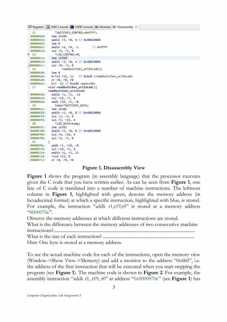
Figure 1. Disassembly View
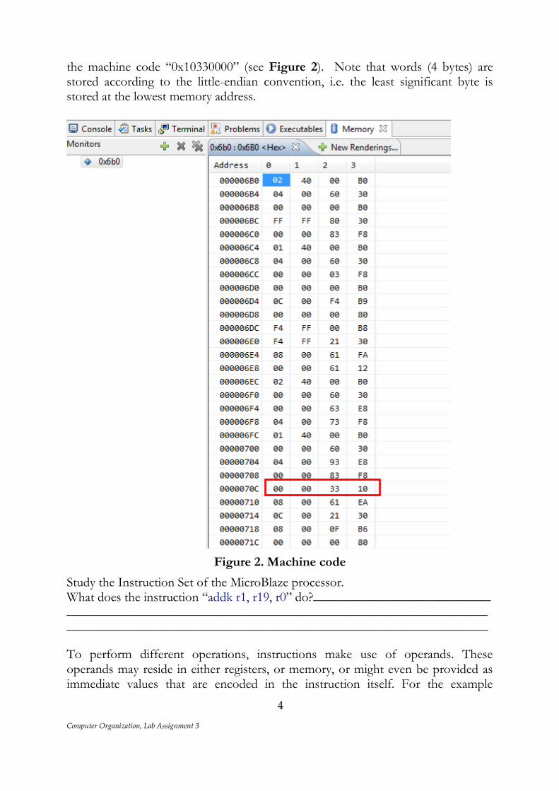
Figure 1 shows the program (in assembly language) that the processor executes given the C code that you have written earlier. As can be seen from Figure 1, one line of C code is translated into a number of machine instructions. The leftmost column in Figure 1, highlighted with green, denotes the memory address (in hexadecimal format) at which a specific instruction, highlighted with blue, is stored. For example, the instruction “addk r1,r19,r0” is stored at a memory address “0000070c”. Observe the memory addresses at which different instructions are stored. What is the difference between the memory addresses of two consecutive machine instructions?_____________________________________________________ What is the size of each instruction? __________________________________ Hint: One byte is stored at a memory address. To see the actual machine code for each of the instructions, open the memory view (Window->Show View->Memory) and add a monitor to the address “0x6b0”, i.e. the address of the first instruction that will be executed when you start stepping the program (see Figure 1). The machine code is shown in Figure 2. For example, the assembly instruction “addk r1, r19, r0” at address “0x0000070c” (see Figure 1) has
Computer Organization, Lab Assignment 3
4
the machine code “0x10330000” (see Figure 2). Note that words (4 bytes) are stored according to the little-endian convention, i.e. the least significant byte is stored at the lowest memory address.
Figure 2. Machine code
Study the Instruction Set of the MicroBlaze processor. What does the instruction “addk r1, r19, r0” do?___________________________ ________________________________________________________________________________________________________________________________
To perform different operations, instructions make use of operands. These operands may reside in either registers, or memory, or might even be provided as immediate values that are encoded in the instruction itself. For the example
Computer Organization, Lab Assignment 3
5
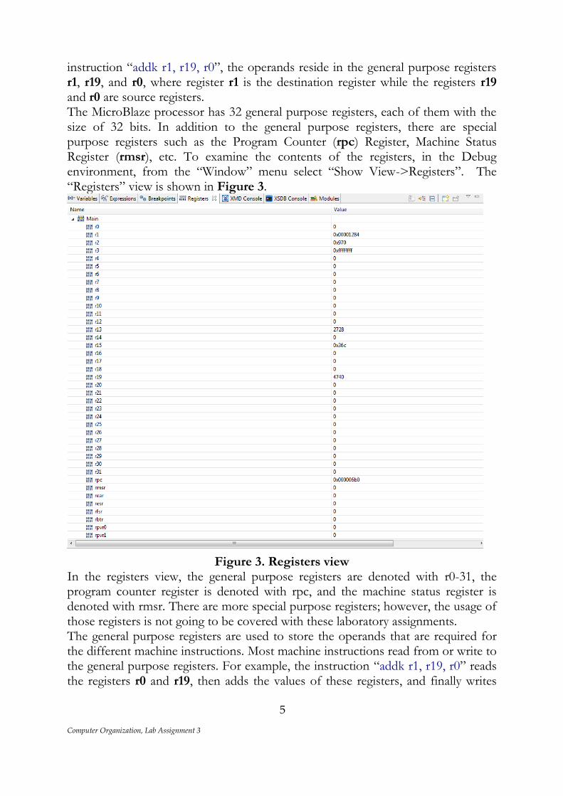
instruction “addk r1, r19, r0”, the operands reside in the general purpose registers r1, r19, and r0, where register r1 is the destination register while the registers r19 and r0 are source registers. The MicroBlaze processor has 32 general purpose registers, each of them with the size of 32 bits. In addition to the general purpose registers, there are special purpose registers such as the Program Counter (rpc) Register, Machine Status Register (rmsr), etc. To examine the contents of the registers, in the Debug environment, from the “Window” menu select “Show View->Registers”. The “Registers” view is shown in Figure 3.
Figure 3. Registers view In the registers view, the general purpose registers are denoted with r0-31, the program counter register is denoted with rpc, and the machine status register is denoted with rmsr. There are more special purpose registers; however, the usage of those registers is not going to be covered with these laboratory assignments. The general purpose registers are used to store the operands that are required for the different machine instructions. Most machine instructions read from or write to the general purpose registers. For example, the instruction “addk r1, r19, r0” reads the registers r0 and r19, then adds the values of these registers, and finally writes
Computer Organization, Lab Assignment 3
6
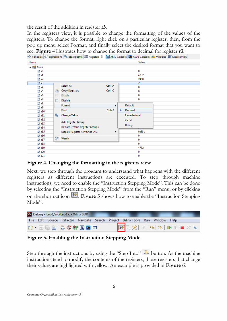
the result of the addition in register r3. In the registers view, it is possible to change the formatting of the values of the registers. To change the format, right click on a particular register, then, from the pop up menu select Format, and finally select the desired format that you want to see. Figure 4 illustrates how to change the format to decimal for register r3.
Figure 4. Changing the formatting in the registers view
Next, we step through the program to understand what happens with the different registers as different instructions are executed. To step through machine instructions, we need to enable the “Instruction Stepping Mode”. This can be done by selecting the “Instruction Stepping Mode” from the “Run” menu, or by clicking
on the shortcut icon . Figure 5 shows how to enable the “Instruction Stepping Mode”.
Figure 5. Enabling the Instruction Stepping Mode
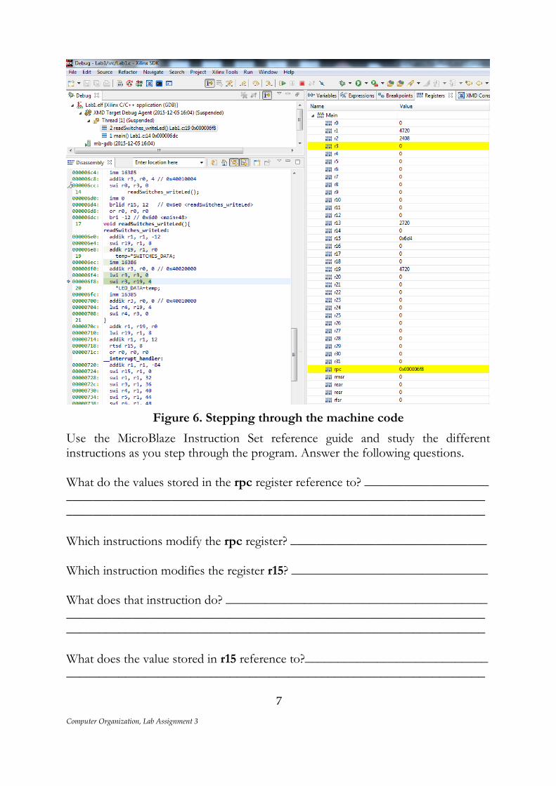
Step through the instructions by using the “Step Into” button. As the machine instructions tend to modify the contents of the registers, those registers that change their values are highlighted with yellow. An example is provided in Figure 6.
Computer Organization, Lab Assignment 3
7
Figure 6. Stepping through the machine code
Use the MicroBlaze Instruction Set reference guide and study the different instructions as you step through the program. Answer the following questions. What do the values stored in the rpc register reference to? ___________________ ________________________________________________________________________________________________________________________________ Which instructions modify the rpc register? ______________________________ Which instruction modifies the register r15? ______________________________ What does that instruction do? ________________________________________ ________________________________________________________________________________________________________________________________ What does the value stored in r15 reference to?____________________________ ________________________________________________________________
Computer Organization, Lab Assignment 3
8
Which instructions are used to load values from memory? __________________ ________________________________________________________________ Which instructions are used to store values in memory? _____________________ ________________________________________________________________ Where is the variable “temp” stored? ___________________________________ What is the address of the “temp” variable? ______________________________ The address of the “temp” variable is obtained by adding an immediate value to the value of register r1. What does the value in the register r1 reference to?__________ ________________________________________________________________ What is the size of the stack frame? ____________________________________ What is stored in the stack frame?______________________________________ ________________________________________________________________________________________________________________________________ Which instruction is used to return from a function call? ____________________ How does the program know where to return? ____________________________ ________________________________________________________________________________________________________________________________ Which register keeps the return address? ________________________________ What happens with the stack pointer before the function returns? _____________ ________________________________________________________________________________________________________________________________
Assignment 2. In Assignment 1, we showed an example where only one function was invoked from the main program, i.e. the function “readSwitches_writeLed”. Furthermore, this function did not use any input arguments and it did not return any outputs. In this assignment, we show what happens when a function (“caller”) invokes another function (“callee”). Furthermore, we show how a “caller” function can pass arguments to a “callee” function, and how a “callee” function returns values to the “caller” function. For that reason, the function “readSwitches_writeLed” is modified such that it invokes two different functions:
Computer Organization, Lab Assignment 3
9
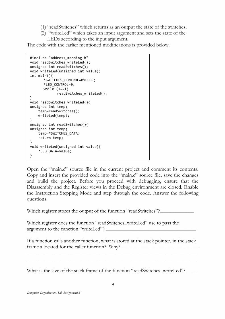
(1) “readSwitches” which returns as an output the state of the switches; (2) “writeLed” which takes an input argument and sets the state of the
LEDs according to the input argument. The code with the earlier mentioned modifications is provided below.
Open the “main.c” source file in the current project and comment its contents. Copy and insert the provided code into the “main.c” source file, save the changes and build the project. Before you proceed with debugging, ensure that the Disassembly and the Register views in the Debug environment are closed. Enable the Instruction Stepping Mode and step through the code. Answer the following questions. Which register stores the output of the function “readSwitches”?_____________ Which register does the function “readSwitches_writeLed” use to pass the argument to the function “writeLed”? __________________________________ If a function calls another function, what is stored at the stack pointer, in the stack frame allocated for the caller function? Why? _____________________________ ________________________________________________________________________________________________________________________________ What is the size of the stack frame of the function “readSwitches_writeLed”? ____
#include "address_mapping.h" void readSwitches_writeLed(); unsigned int readSwitches(); void writeLed(unsigned int value); int main(){ *SWITCHES_CONTROL=0xFFFF; *LED_CONTROL=0; while (1==1) readSwitches_writeLed(); } void readSwitches_writeLed(){ unsigned int temp; temp=readSwitches(); writeLed(temp); } unsigned int readSwitches(){ unsigned int temp; temp=*SWITCHES_DATA; return temp; } void writeLed(unsigned int value){ *LED_DATA=value; }
Computer Organization, Lab Assignment 3
10
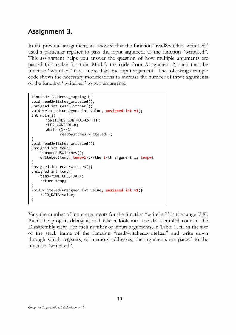
Assignment 3. In the previous assignment, we showed that the function “readSwitches_writeLed” used a particular register to pass the input argument to the function “writeLed”. This assignment helps you answer the question of how multiple arguments are passed to a callee function. Modify the code from Assignment 2, such that the function “writeLed” takes more than one input argument. The following example code shows the necessary modifications to increase the number of input arguments of the function “writeLed” to two arguments.
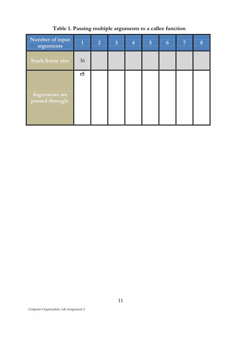
Vary the number of input arguments for the function “writeLed” in the range [2,8]. Build the project, debug it, and take a look into the disassembled code in the Disassembly view. For each number of inputs arguments, in Table 1, fill in the size of the stack frame of the function “readSwitches_writeLed” and write down through which registers, or memory addresses, the arguments are passed to the function “writeLed”.
#include "address_mapping.h" void readSwitches_writeLed(); unsigned int readSwitches(); void writeLed(unsigned int value, unsigned int v1); int main(){ *SWITCHES_CONTROL=0xFFFF; *LED_CONTROL=0; while (1==1) readSwitches_writeLed(); } void readSwitches_writeLed(){ unsigned int temp; temp=readSwitches(); writeLed(temp, temp+1);//the i-th argument is temp+i } unsigned int readSwitches(){ unsigned int temp; temp=*SWITCHES_DATA; return temp; } void writeLed(unsigned int value, unsigned int v1){ *LED_DATA=value; }
Computer Organization, Lab Assignment 3
11
Table 1. Passing multiple arguments to a callee function
Number of input arguments
1 2 3 4 5 6 7 8
Stack frame size 36
Arguments are passed through:
r5
Computer Organization, Lab Assignment 3
12
Assembly programming When writing a program in a high-level programming language, such as C, a programmer does not need to know the inside of a processor on which this program executes. Assembly programming on the other hand, requires that the programmer has a better knowledge of the processor on which the program is going to be executed. In other words, the programmer needs to know the architecture of the processor, i.e. the programmer needs to know how many registers are available, what is the size of these registers, what are the different instructions that the processor is capable of executing, etc. In Assignment 1-3 of this lab, we looked at a disassembled code which is much easier to read than a machine code. The disassembled code is the translation of the machine code into assembly language. The machine code was obtained by a compiler, i.e. a software tool that translates a code written in a high-level programming language into machine code. Similar to the compiler, an assembler is a software tool that translates a code written in assembly language into machine code. In the following assignments, we show examples on how we can write programs in assembly language. One of the major advantages of writing a program in assembly language is that one can obtain access to specific registers inside the processor, which may not be possible when one uses a high-level programming language. Furthermore, writing a program in assembly may result in much more optimized code, and thus improve efficiency.
Assignment 4. The purpose of this assignment is to write an assembly subroutine (a function) that reads the state of the switches and correspondingly sets the state of the LEDs. To write the assembly program, we need to create a new source file. The source files that contain code written in assembly language have the extension “.S”. To add a new source file in the project, the following steps should be performed. In the current project, select the “src” folder. Right click the “src” folder, and from the pop up menu select “New->File”. In the pop up window, for the file name, enter “AssemblyImplementation.S”. These steps add a new source file in the project. The assembly subroutine will be written in this source file.
Computer Organization, Lab Assignment 3
13
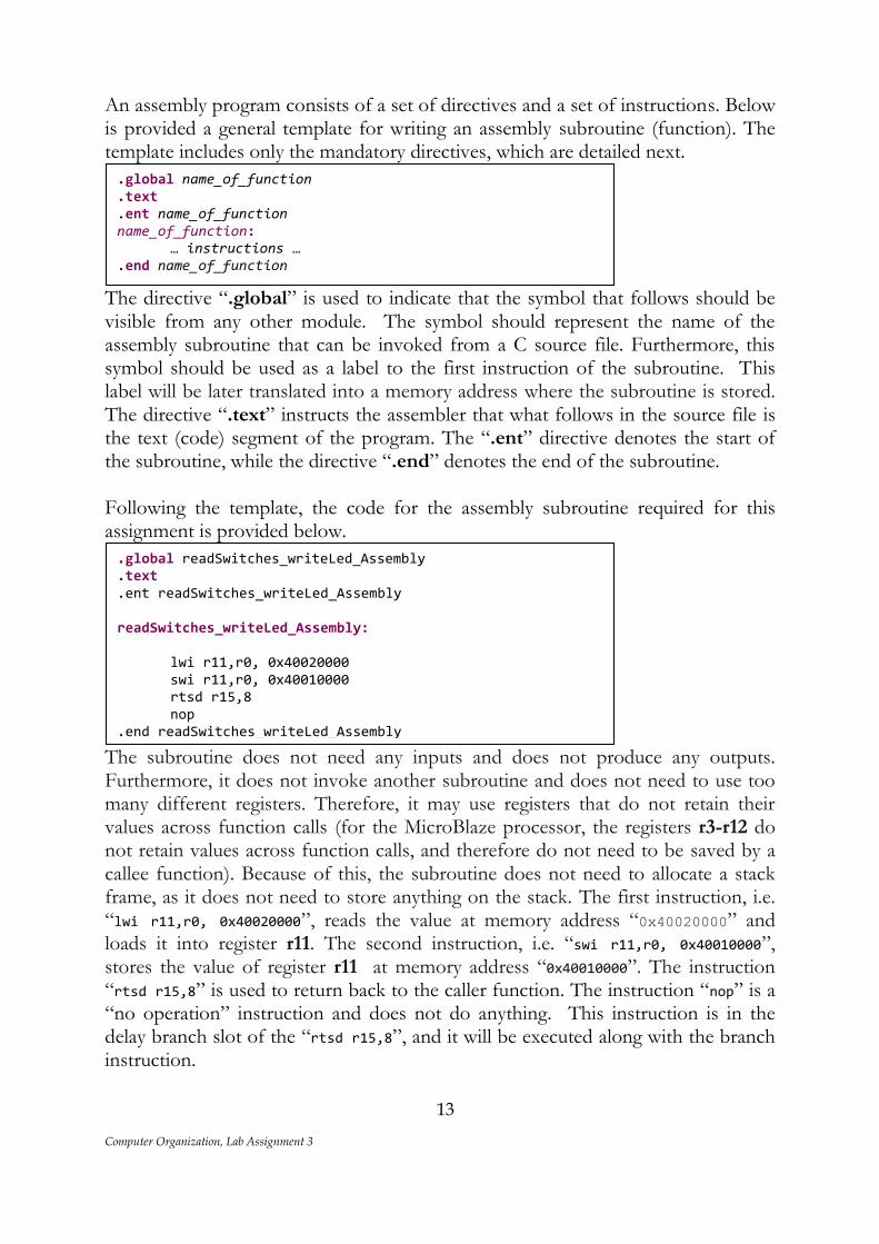
An assembly program consists of a set of directives and a set of instructions. Below is provided a general template for writing an assembly subroutine (function). The template includes only the mandatory directives, which are detailed next.
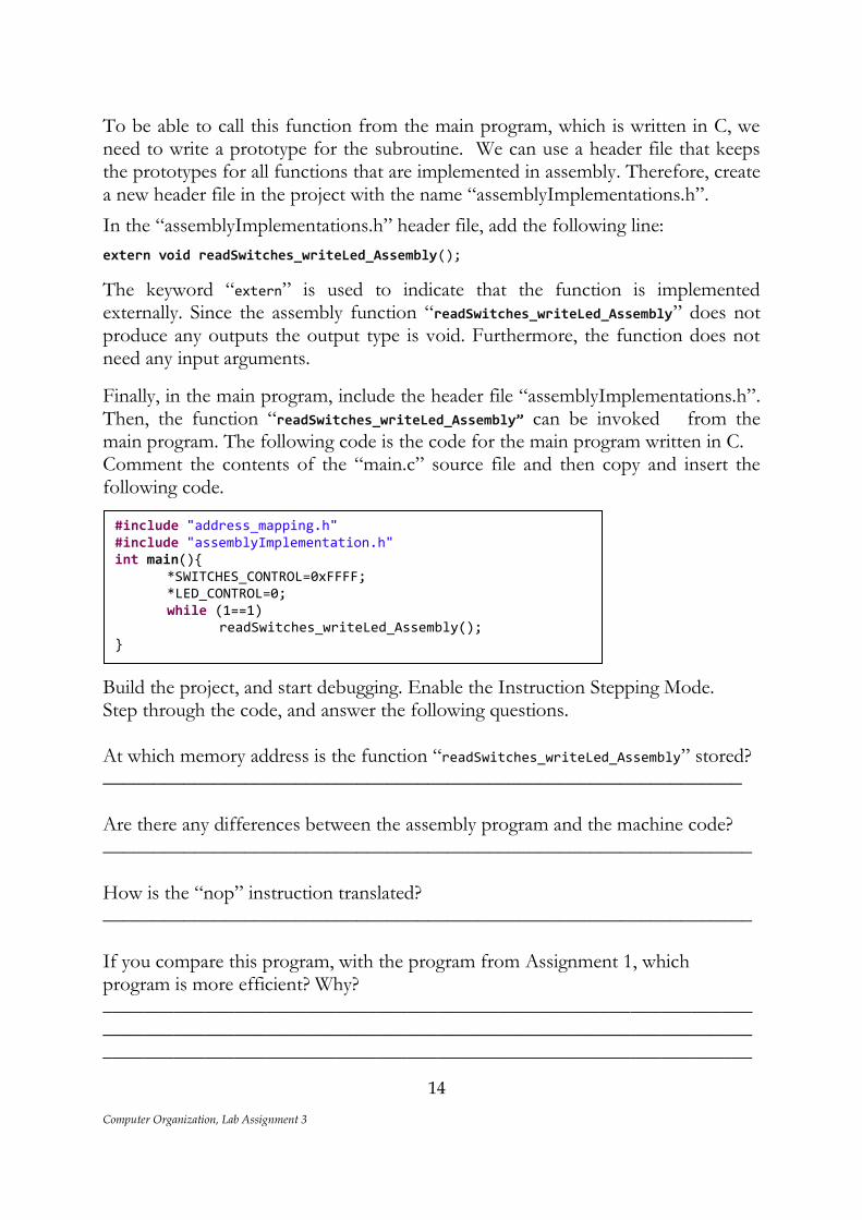
The directive “.global” is used to indicate that the symbol that follows should be visible from any other module. The symbol should represent the name of the assembly subroutine that can be invoked from a C source file. Furthermore, this symbol should be used as a label to the first instruction of the subroutine. This label will be later translated into a memory address where the subroutine is stored. The directive “.text” instructs the assembler that what follows in the source file is the text (code) segment of the program. The “.ent” directive denotes the start of the subroutine, while the directive “.end” denotes the end of the subroutine. Following the template, the code for the assembly subroutine required for this assignment is provided below.
The subroutine does not need any inputs and does not produce any outputs. Furthermore, it does not invoke another subroutine and does not need to use too many different registers. Therefore, it may use registers that do not retain their values across function calls (for the MicroBlaze processor, the registers r3-r12 do not retain values across function calls, and therefore do not need to be saved by a callee function). Because of this, the subroutine does not need to allocate a stack frame, as it does not need to store anything on the stack. The first instruction, i.e. “lwi r11,r0, 0x40020000”, reads the value at memory address “0x40020000” and loads it into register r11. The second instruction, i.e. “swi r11,r0, 0x40010000”, stores the value of register r11 at memory address “0x40010000”. The instruction “rtsd r15,8” is used to return back to the caller function. The instruction “nop” is a “no operation” instruction and does not do anything. This instruction is in the delay branch slot of the “rtsd r15,8”, and it will be executed along with the branch instruction.
.global readSwitches_writeLed_Assembly
.text
.ent readSwitches_writeLed_Assembly readSwitches_writeLed_Assembly: lwi r11,r0, 0x40020000 swi r11,r0, 0x40010000 rtsd r15,8 nop .end readSwitches_writeLed_Assembly
.global name_of_function
.text
.ent name_of_function name_of_function: … instructions … .end name_of_function
Computer Organization, Lab Assignment 3
14
To be able to call this function from the main program, which is written in C, we need to write a prototype for the subroutine. We can use a header file that keeps the prototypes for all functions that are implemented in assembly. Therefore, create a new header file in the project with the name “assemblyImplementations.h”.
In the “assemblyImplementations.h” header file, add the following line:
extern void readSwitches_writeLed_Assembly();
The keyword “extern” is used to indicate that the function is implemented externally. Since the assembly function “readSwitches_writeLed_Assembly” does not produce any outputs the output type is void. Furthermore, the function does not need any input arguments.
Finally, in the main program, include the header file “assemblyImplementations.h”. Then, the function “readSwitches_writeLed_Assembly” can be invoked from the main program. The following code is the code for the main program written in C. Comment the contents of the “main.c” source file and then copy and insert the following code.
Build the project, and start debugging. Enable the Instruction Stepping Mode. Step through the code, and answer the following questions. At which memory address is the function “readSwitches_writeLed_Assembly” stored? _______________________________________________________________ Are there any differences between the assembly program and the machine code? ________________________________________________________________ How is the “nop” instruction translated? ________________________________________________________________ If you compare this program, with the program from Assignment 1, which program is more efficient? Why? ________________________________________________________________________________________________________________________________________________________________________________________________
#include "address_mapping.h" #include "assemblyImplementation.h" int main(){ *SWITCHES_CONTROL=0xFFFF; *LED_CONTROL=0; while (1==1) readSwitches_writeLed_Assembly(); }
Computer Organization, Lab Assignment 3
15
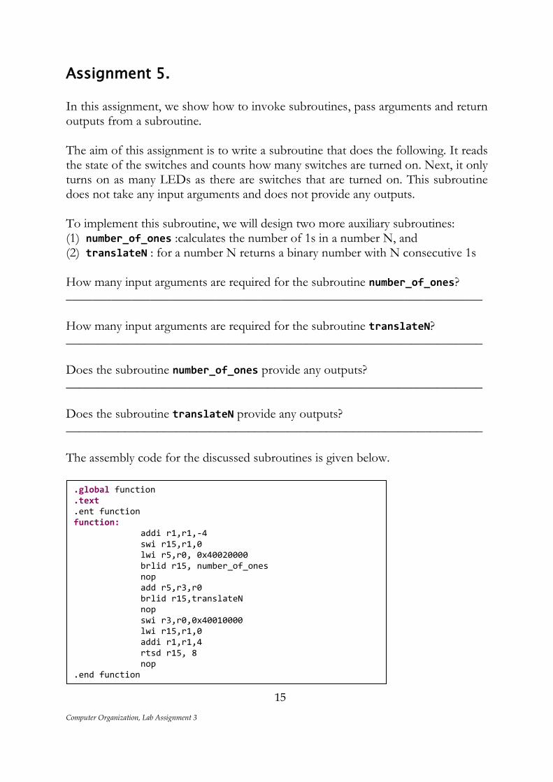
Assignment 5. In this assignment, we show how to invoke subroutines, pass arguments and return outputs from a subroutine. The aim of this assignment is to write a subroutine that does the following. It reads the state of the switches and counts how many switches are turned on. Next, it only turns on as many LEDs as there are switches that are turned on. This subroutine does not take any input arguments and does not provide any outputs. To implement this subroutine, we will design two more auxiliary subroutines: (1) number_of_ones :calculates the number of 1s in a number N, and (2) translateN : for a number N returns a binary number with N consecutive 1s How many input arguments are required for the subroutine number_of_ones? ________________________________________________________________ How many input arguments are required for the subroutine translateN? ________________________________________________________________ Does the subroutine number_of_ones provide any outputs? ________________________________________________________________ Does the subroutine translateN provide any outputs? ________________________________________________________________ The assembly code for the discussed subroutines is given below.
.global function
.text
.ent function function: addi r1,r1,-4 swi r15,r1,0 lwi r5,r0, 0x40020000 brlid r15, number_of_ones nop add r5,r3,r0 brlid r15,translateN nop swi r3,r0,0x40010000 lwi r15,r1,0 addi r1,r1,4 rtsd r15, 8 nop .end function .global translateN .text .ent translateN translateN: addi r3,r0,1 again: beqid r5, done nop addi r5,r5,-1 add r3,r3,r3
Computer Organization, Lab Assignment 3
16
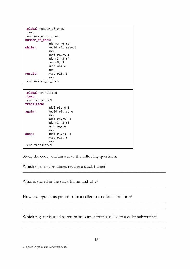
Study the code, and answer to the following questions. Which of the subroutines require a stack frame? ________________________________________________________________ What is stored in the stack frame, and why? ________________________________________________________________ How are arguments passed from a caller to a callee subroutine? ________________________________________________________________________________________________________________________________ Which register is used to return an output from a callee to a caller subroutine? ________________________________________________________________ ________________________________________________________________
.global number_of_ones
.text
.ent number_of_ones number_of_ones: add r3,r0,r0 while: beqid r5, result nop andi r4,r5,1 add r3,r3,r4 sra r5,r5 brid while nop result: rtsd r15, 8 nop .end number_of_ones
.global translateN
.text
.ent translateN translateN: addi r3,r0,1 again: beqid r5, done nop addi r5,r5,-1 add r3,r3,r3 brid again nop done: addi r3,r3,-1 rtsd r15, 8 nop .end translateN .global number_of_ones .text .ent number_of_ones number_of_ones: add r3,r0,r0 while: beqid r5, result nop andi r4,r5,1 add r3,r3,r4 sra r5,r5 brid while nop result: rtsd r15, 8 nop .end number_of_ones
Computer Organization, Lab Assignment 3
17
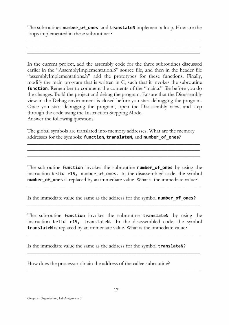
The subroutines number_of_ones and translateN implement a loop. How are the loops implemented in these subroutines? ________________________________________________________________________________________________________________________________________________________________________________________________ In the current project, add the assembly code for the three subroutines discussed earlier in the “AssemblyImplementation.S” source file, and then in the header file “assemblyImplementations.h” add the prototypes for these functions. Finally, modify the main program that is written in C, such that it invokes the subroutine function. Remember to comment the contents of the “main.c” file before you do the changes. Build the project and debug the program. Ensure that the Disassembly view in the Debug environment is closed before you start debugging the program. Once you start debugging the program, open the Disassembly view, and step through the code using the Instruction Stepping Mode. Answer the following questions. The global symbols are translated into memory addresses. What are the memory addresses for the symbols: function, translateN, and number_of_ones? ________________________________________________________________ ________________________________________________________________ ________________________________________________________________ The subroutine function invokes the subroutine number_of_ones by using the instruction brlid r15, number_of_ones. In the disassembled code, the symbol number_of_ones is replaced by an immediate value. What is the immediate value? ________________________________________________________________ Is the immediate value the same as the address for the symbol number_of_ones? ____________________________________________________________________ The subroutine function invokes the subroutine translateN by using the instruction brlid r15, translateN. In the disassembled code, the symbol translateN is replaced by an immediate value. What is the immediate value? ________________________________________________________________ Is the immediate value the same as the address for the symbol translateN? ____________________________________________________________________ How does the processor obtain the address of the callee subroutine? ________________________________________________________________
Computer Organization, Lab Assignment 3
18
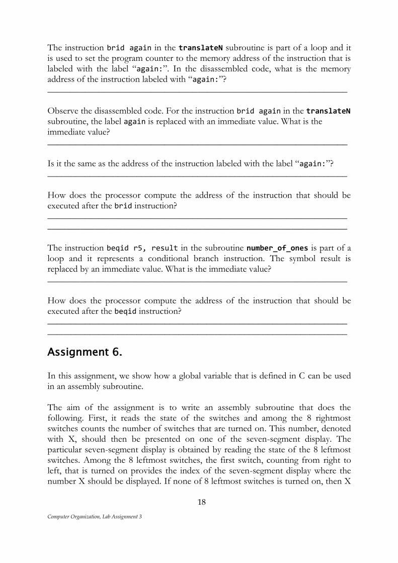
The instruction brid again in the translateN subroutine is part of a loop and it is used to set the program counter to the memory address of the instruction that is labeled with the label “again:”. In the disassembled code, what is the memory address of the instruction labeled with “again:”? ________________________________________________________________ Observe the disassembled code. For the instruction brid again in the translateN subroutine, the label again is replaced with an immediate value. What is the immediate value? ________________________________________________________________ Is it the same as the address of the instruction labeled with the label “again:”? ________________________________________________________________ How does the processor compute the address of the instruction that should be executed after the brid instruction? ________________________________________________________________ ________________________________________________________________ The instruction beqid r5, result in the subroutine number_of_ones is part of a loop and it represents a conditional branch instruction. The symbol result is replaced by an immediate value. What is the immediate value? ________________________________________________________________ How does the processor compute the address of the instruction that should be executed after the beqid instruction? ________________________________________________________________________________________________________________________________
Assignment 6. In this assignment, we show how a global variable that is defined in C can be used in an assembly subroutine. The aim of the assignment is to write an assembly subroutine that does the following. First, it reads the state of the switches and among the 8 rightmost switches counts the number of switches that are turned on. This number, denoted with X, should then be presented on one of the seven-segment display. The particular seven-segment display is obtained by reading the state of the 8 leftmost switches. Among the 8 leftmost switches, the first switch, counting from right to left, that is turned on provides the index of the seven-segment display where the number X should be displayed. If none of 8 leftmost switches is turned on, then X
Computer Organization, Lab Assignment 3
19
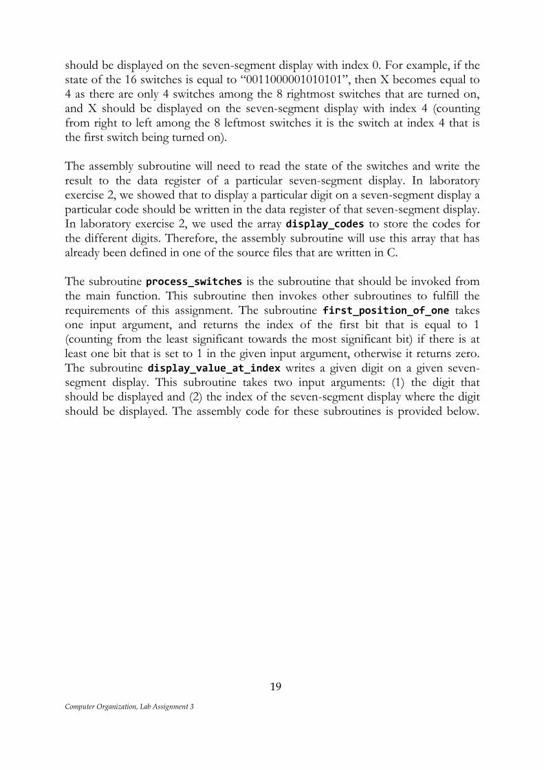
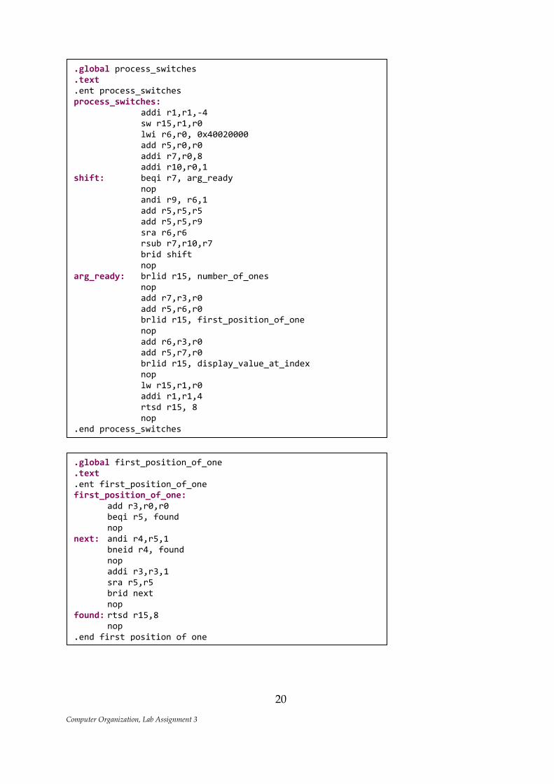
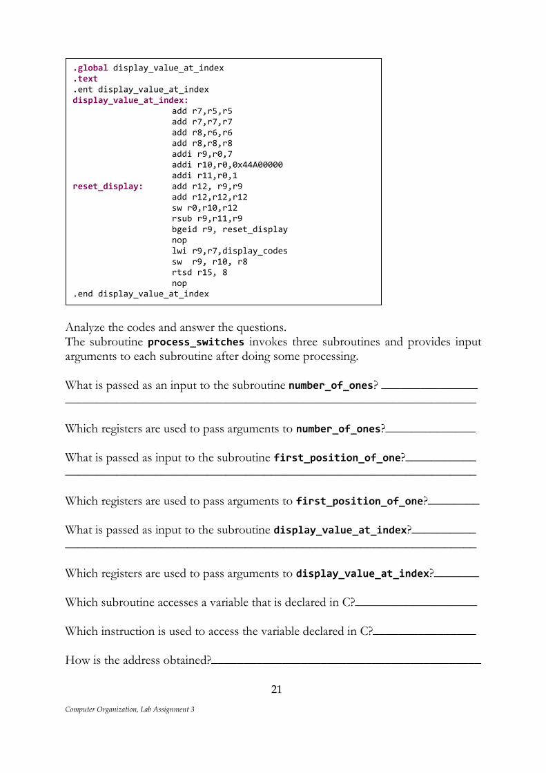
should be displayed on the seven-segment display with index 0. For example, if the state of the 16 switches is equal to “0011000001010101”, then X becomes equal to 4 as there are only 4 switches among the 8 rightmost switches that are turned on, and X should be displayed on the seven-segment display with index 4 (counting from right to left among the 8 leftmost switches it is the switch at index 4 that is the first switch being turned on). The assembly subroutine will need to read the state of the switches and write the result to the data register of a particular seven-segment display. In laboratory exercise 2, we showed that to display a particular digit on a seven-segment display a particular code should be written in the data register of that seven-segment display. In laboratory exercise 2, we used the array display_codes to store the codes for the different digits. Therefore, the assembly subroutine will use this array that has already been defined in one of the source files that are written in C. The subroutine process_switches is the subroutine that should be invoked from the main function. This subroutine then invokes other subroutines to fulfill the requirements of this assignment. The subroutine first_position_of_one takes one input argument, and returns the index of the first bit that is equal to 1 (counting from the least significant towards the most significant bit) if there is at least one bit that is set to 1 in the given input argument, otherwise it returns zero. The subroutine display_value_at_index writes a given digit on a given seven-segment display. This subroutine takes two input arguments: (1) the digit that should be displayed and (2) the index of the seven-segment display where the digit should be displayed. The assembly code for these subroutines is provided below.
Computer Organization, Lab Assignment 3
20
.global first_position_of_one
.text
.ent first_position_of_one first_position_of_one: add r3,r0,r0 beqi r5, found nop next: andi r4,r5,1 bneid r4, found nop addi r3,r3,1 sra r5,r5 brid next nop found: rtsd r15,8 nop .end first_position_of_one .global display_value_at_index .text .ent display_value_at_index display_value_at_index: add r7,r5,r5 add r7,r7,r7 add r8,r6,r6 add r8,r8,r8 addi r9,r0,7 addi r10,r0,0x44A00000 addi r11,r0,1 reset_display: add r12, r9,r9
.global process_switches
.text
.ent process_switches process_switches: addi r1,r1,-4 sw r15,r1,r0 lwi r6,r0, 0x40020000 add r5,r0,r0 addi r7,r0,8 addi r10,r0,1 shift: beqi r7, arg_ready nop andi r9, r6,1 add r5,r5,r5 add r5,r5,r9 sra r6,r6 rsub r7,r10,r7 brid shift nop arg_ready: brlid r15, number_of_ones nop add r7,r3,r0 add r5,r6,r0 brlid r15, first_position_of_one nop add r6,r3,r0 add r5,r7,r0 brlid r15, display_value_at_index nop lw r15,r1,r0 addi r1,r1,4 rtsd r15, 8 nop .end process_switches .global first_position_of_one .text .ent first_position_of_one first_position_of_one: add r3,r0,r0 beqi r5, found nop next: andi r4,r5,1 bneid r4, found nop addi r3,r3,1 sra r5,r5 brid next nop found: rtsd r15,8 nop .end first_position_of_one .global display_value_at_index .text .ent display_value_at_index display_value_at_index: add r7,r5,r5 add r7,r7,r7 add r8,r6,r6 add r8,r8,r8 addi r9,r0,7 addi r10,r0,0x44A00000 addi r11,r0,1 reset_display: add r12, r9,r9 add r12,r12,r12
Computer Organization, Lab Assignment 3
21
Analyze the codes and answer the questions. The subroutine process_switches invokes three subroutines and provides input arguments to each subroutine after doing some processing. What is passed as an input to the subroutine number_of_ones? _______________ ________________________________________________________________ Which registers are used to pass arguments to number_of_ones?______________ What is passed as input to the subroutine first_position_of_one?___________ ________________________________________________________________ Which registers are used to pass arguments to first_position_of_one?________ What is passed as input to the subroutine display_value_at_index?__________ ________________________________________________________________ Which registers are used to pass arguments to display_value_at_index?_______ Which subroutine accesses a variable that is declared in C?___________________ Which instruction is used to access the variable declared in C?________________ How is the address obtained?__________________________________________
.global display_value_at_index
.text
.ent display_value_at_index display_value_at_index: add r7,r5,r5 add r7,r7,r7 add r8,r6,r6 add r8,r8,r8 addi r9,r0,7 addi r10,r0,0x44A00000 addi r11,r0,1 reset_display: add r12, r9,r9 add r12,r12,r12 sw r0,r10,r12 rsub r9,r11,r9 bgeid r9, reset_display nop lwi r9,r7,display_codes sw r9, r10, r8 rtsd r15, 8 nop .end display_value_at_index
Computer Organization, Lab Assignment 3
22
In the current project, copy and add the assembly code for the three subroutines discussed earlier in the “AssemblyImplementation.S” source file, and then in the header file “assemblyImplementations.h” add the prototypes for these functions. Finally, modify the main program, such that it invokes the subroutine process_switches. Remember to comment the contents of the “main.c” source file before you do the modifications. Build the project and debug the program. Ensure that the Disassembly view in the Debug environment is closed before you start debugging the program. Once you start debugging the program, open the Disassembly view, and step through the code using the Instruction Stepping Mode.
Assignment 7.
Write an assembly subroutine that does the following. It reads the state of the switches and then compares the binary number LEFT, obtained from the 8 leftmost switches with the binary number RIGHT, obtained from the 8 rightmost switches. If LEFT is greater than RIGHT, then all LEDs are turned-on, otherwise all LEDs are turned-off. For example, it the state of the switches is “0111111100111111” then LEFT is evaluated as “01111111” and RIGHT is evaluated as “00111111”. Since for this example, LEFT is greater than RIGHT, all LEDs should be turned-on. Test the subroutine by invoking it from the main program.
Assignment 8.
Write an assembly subroutine that does the following. It reads the state of the switches and then compares the binary number LEFT, obtained from the 8 leftmost switches with the binary number RIGHT, obtained from the 8 rightmost switches. If the bits in the LEFT and the RIGHT number at position I are the same, then the seven-segment display with index I displays as ‘1’, otherwise it displays a zero. For example, if the state of the switches is “0111011101010101”, LEFT is evaluated as “01110111” and RIGHT is evaluated as “01010101” and therefore, the values displayed on the 8 seven-segment display should be “11011101”. Test the subroutine by invoking it from the main program.
Assignment 9.
Write an assembly subroutine that reads the state of the switches, and displays the number of switches that are turned-on on the seven-segment displays. Note that it is possible to have more than nine switches that are turned-on. For example, if seven switches are turned-on, then only the rightmost display shows the value “7”. However, if 10 switches are turned-on, then the two rightmost displays show the values “1” and “0”, respectively. Test the subroutine by invoking it from the main program.