machine tools and metrology laborartory lab manual.pdflab manual academic year : 2019 - 2020 course...
TRANSCRIPT
MACHINE TOOLS AND METROLOGY
LABORARTORY
LAB MANUAL
Academic Year : 2019 - 2020
Course Code : AME110
Regulations : IARE – R16
Semester : V
Branch : ME
Prepared by
Dr. K. Ch Apparao Associate Professor
INSTITUTE OF AERONAUTICAL ENGINEERING (Autonomous)
Dundigal, Hyderabad - 500 043

MACHINE TOOLS AND METROLOGY
2
INSTITUTE OF AERONAUTICAL ENGINEERING (Autonomous)
Dundigal, Hyderabad – 500043
Program Outcomes
PO1 Engineering Knowledge Capability to apply the knowledge of mathematics, science and engineering in the field of mechanical engineering.
PO2 Problem Analysis: An ability to analyze complex engineering problems to arrive at relevant
conclusion using knowledge of mathematics, science and engineering.
PO3 Design/development of solutions: Competence to design a system, component or process to meet
societal needs within realistic constraints.
PO4 Conduct investigations of complex problems: To design and conduct research oriented experiments as well as to analyze and implement data using research methodologies.
PO5 Modern tool usage: Create, select, and apply appropriate techniques, resources, and modern
engineering and IT tools including prediction and modeling to complex engineering activities with an
understanding of the limitations.
PO6 The engineer and society: Apply reasoning informed by the contextual knowledge to assess societal, health, safety, legal and cultural issues and the consequent responsibilities relevant to the
professional engineering practice.
PO7 Environment and sustainability: Understand the impact of the professional engineering solutions
in societal and environmental contexts, and demonstrate the knowledge of, and need for sustainable
development.
PO8 Ethics: Apply ethical principles and commit to professional ethics and responsibilities and norms of
the engineering practice.
PO9 Individual and team work: Function effectively as an individual, and as a member or leader in
diverse teams, and in multidisciplinary settings.
PO10 Communication: Communicate effectively on complex engineering activities with the engineering
community and with society at large, such as, being able to comprehend and write effective reports
and design documentation, make effective presentations, and give and receive clear instructions.
PO11 Project management and finance: Demonstrate knowledge and understanding of the engineering
and management principles and apply these to one’s own work, as a member and leader in a team, to
manage projects and in multidisciplinary environments.
PO12 Life-long learning: Recognize the need for, and have the preparation and ability to engage in
independent and life-long learning in the broadest context of technological change.
Program Specific Outcomes
PSO1 Professional Skills: To produce engineering professional capable of synthesizing and analyzing
mechanical systems including allied engineering streams.
PSO2 Problem solving skills: An ability to adopt and integrate current technologies in the design and
manufacturing domain to enhance the employability.
PSO3 Successful career and Entrepreneurship: To build the nation, by imparting technological inputs
and managerial skills to become technocrats.
MACHINE TOOLS AND METROLOGY
3
INSTITUTE OF AERONAUTICAL ENGINEERING (Autonomous)
Dundigal, Hyderabad – 500043
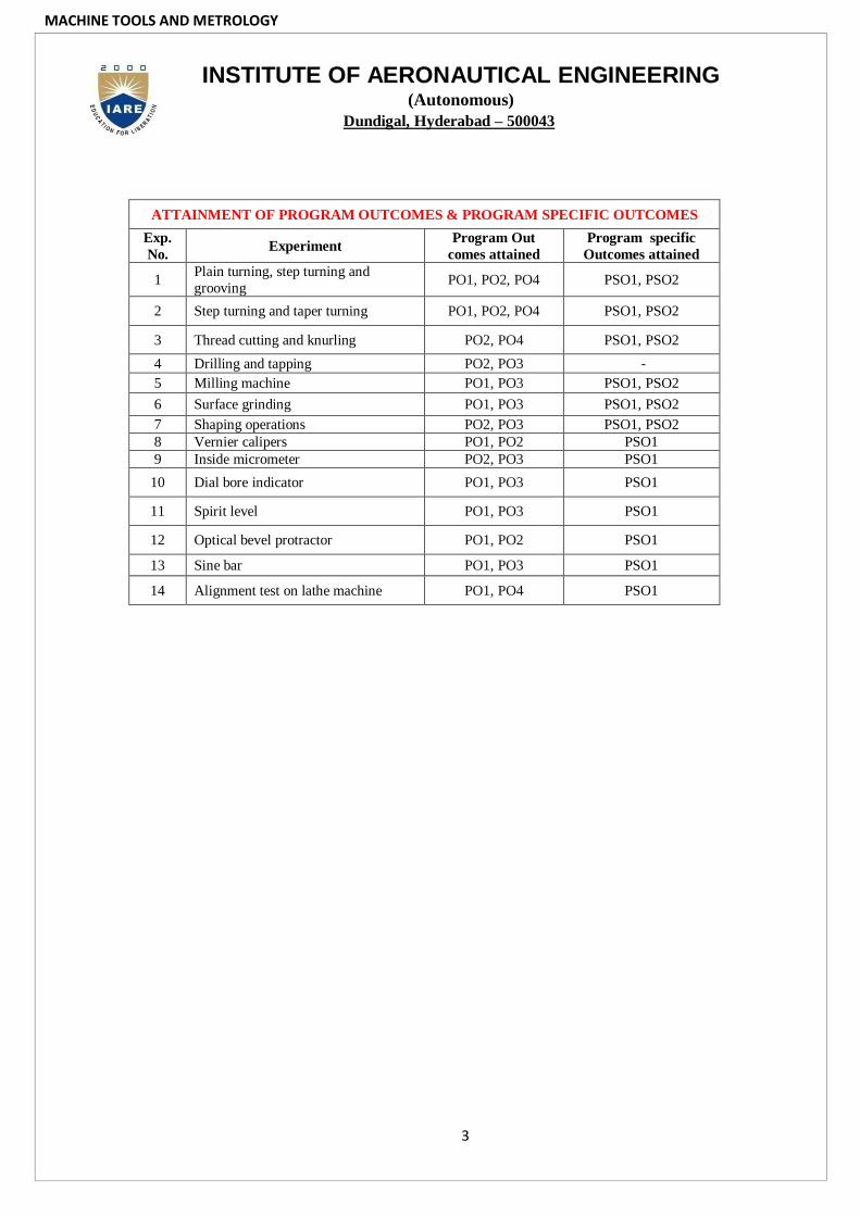
ATTAINMENT OF PROGRAM OUTCOMES & PROGRAM SPECIFIC OUTCOMES
Exp.
No. Experiment
Program Out
comes attained
Program specific
Outcomes attained
1 Plain turning, step turning and
grooving PO1, PO2, PO4 PSO1, PSO2
2 Step turning and taper turning PO1, PO2, PO4 PSO1, PSO2
3 Thread cutting and knurling PO2, PO4 PSO1, PSO2
4 Drilling and tapping PO2, PO3 -
5 Milling machine PO1, PO3 PSO1, PSO2
6 Surface grinding PO1, PO3 PSO1, PSO2
7 Shaping operations PO2, PO3 PSO1, PSO2
8 Vernier calipers PO1, PO2 PSO1
9 Inside micrometer PO2, PO3 PSO1
10 Dial bore indicator PO1, PO3 PSO1
11 Spirit level PO1, PO3 PSO1
12 Optical bevel protractor PO1, PO2 PSO1
13 Sine bar PO1, PO3 PSO1
14 Alignment test on lathe machine PO1, PO4 PSO1

MACHINE TOOLS AND METROLOGY
4
INSTITUTE OF AERONAUTICAL ENGINEERING (Autonomous)
Dundigal, Hyderabad - 500 043
CCeerrttiiffiiccaattee
This is to certify that it is a bonafied record of Practical work done by
Sri/Kum. bearing the
Roll No. of Class
Branch in the
laboratory during the Academic
year under our supervision.
Head of the Department Lecture In-Charge
External Examiner Internal Examiner

MACHINE TOOLS AND METROLOGY
5
MACHINE TOOLS AND METROLOGY LABORATORY
V Semester: ME
Course Code Category Hours / Week Credits Maximum Marks
AME110
Core
L T P C CIA SEE Total
- - 2 1 30 70 100
Contact Classes: Nil Tutorial Classes: Nil Practical Classes: 42 Total Classes: 42
COURSE OBJECTIVES:
The course should enable the students to: I. Learn the Step turning and taper turning and thread cutting Drilling and Tapping on the
lathe machine
II. The operations of Shaping and Planing and milling
III. Learn the measurement of the Angle and tapers by Bevel protractor, Sine bars, etc.
LIST OF EXPERIMENTS
Week - 1 LATHE MACHINE
Plain turning, step turning and grooving by Lathe Machine
Week - 2 LATHE MACHINE
Step turning and taper turning by Lathe Machine
Week - 3 LATHE MACHINE
Thread cutting and knurling using lathe machine
Week - 4 DRILLING AND STEP BORING
Drilling, tapping and step boring using drilling machine.
Week - 5 MILLING MACHINE
Milling of gear
Week - 6 SURFACE GRINDING
surface grinding of given work piece
Week -7 SHAPING OPERATIONS
Shaping of V-groove using shaper
Week - 8 VERNIER CALIPERS
Diameter measuring using vernier calipers
Week - 9 INSIDE MICROMETER
diameter measuring using micrometer
Week - 10 DIAL BORE INDICATOR
Bore measurement using bore gauge.
Week - 11 SPIRIT LEVEL
To chuck the flatness of given surface plate.

MACHINE TOOLS AND METROLOGY
6
Week - 12 OPTICAL BEVEL PROTRACTOR
Tool angle measurements using bevel protractor
Week - 13 ANGLE MEASUREMENTS
Tool angle measurements using sine bar, slip gauges
Week - 14 ALIGNMENT TEST ON LATHE MACHINE
To perform alignment test on lathe
Week - 15 EXAMINATIONS
Reference Books:
1. B. S. Raghu Vamshi, “Workshop Technology Vol – II”, Dhanpat Rai Publishers, 9th Edition, 2010.
2. H.M.T. (Hindustan Machine Tools), “Production Technology”, Tata McGraw-Hill Education (P)
Ltd, 2nd Edition, 1980.
3. Jain R.K., “Engineering Metrology”, Khanna Publishers, 1st Edition, 2005.
Web References:
1. https://www.ocw.mit.edu/courses/mechanical-engineering/
2. http://www.nptel.ac.in/courses/112106138

MACHINE TOOLS AND METROLOGY
7
WEEK – 1
EXPERIMENT - 1: PLAIN TURNING, STEP TURNING AND GROOVING
OBJECTIVE:-
To perform plain turning, step turning and Grooving on a circular rod so as to obtain the required
design as per drawing using lathe machine
RESOURCES:-
Measuring tools – Outside calipers and steel rule
Manufacturing tools – Single point cutting tools, chuck key, tool part keys, spanner and brush
MATERIALS REQUIRED:-
Circular cross section rod of length 120mm and diameter 20 mm
PROCEDURE:-
1. Inspect the Mild Steel raw material using Vernier calipers. The work piece is held in the chuck by placing it properly and tightening its using the chuck key.
2. Now single point cutting tool is placed in the tool post and properly arranged to the centre of the work
piece.
3. Work piece is rotated by switching on the motor.
4. Perform the Facing operations on both sides and maintain the given dimensions.
5. First the plain turning operation is carried out by placing the tool at 1mm feed to the lathe axis.
6. After that step turning operation is performed till the desired diameter is obtained.
7. Perform Centre Drill operation up to 10 mm required dimension.
PRECAUTIONS:-
8. Check the machine speed before starting the experiment.
9. Chuck key must be removed from the chuck before starting the machine.
10. Feed should be given gradually.
PRE LAB QUESTIONS:-
11. What is Lathe?
12. How do you specify the Lathe?
13. Describe the different parts of Lathe?
14. List any four types of lathe?
POST LAB QUESTIONS:-
I. Calculate the taper angle of given specimen?
II. What is a semi-automatic lathe?
III. What is copying lathe?
IV. What is a semi-automatic lathe?
RESULT:-
The work piece of required dimensions is obtained by plain and step turning on lathe.

MACHINE TOOLS AND METROLOGY
8

MACHINE TOOLS AND METROLOGY
9
WEEK – 2
EXPERIMENT - 2: STEP TURNING AND TAPER TURNING
OBJECTIVE: -
To perform the step turning and taper turning on a circular rod so as to obtain the required design as per the
drawing using the lathe machine.
RESOURCES:-
Measuring tools – outside calipers and steel rule.
Manufacturing tools – SINGLE point cutting tool, chuck key, tool post key, spanner and brush
Materials required – Circular C.S rod of length 105mm and diameter 32mm.
MATERIALS REQUIRED:-
Circular cross section rod of length 120mm and diameter 20 mm
PROCEDURE:-
1. Inspect the raw material using Vernier caliper
2. The w/p is held in the chuck head by placing it properly and tightening using chuckkey.
3. Now the single point cutting tool is placed in the tool post and properly arranged to the centre of w/p.
4. W/p is rotated by switching on the motor. First the facing operation is carried out by pointing the
cutting tool at an angle 450 to the lathe.
5. After that step turning the operation is carried out by pointing the tool 900to the lathe axis.
6. For taper turning the taper angle is calculated with the help of d = tan-1 D-d / 2L
7. The compound rest is turned to the required taper angle and the taper turning operation is
performed.
PRECAUTIONS:-
8. Check the machine speed before starting the experiment.
9. Chuck key must be removed from the chuck before starting the machine.
10. Feed should be given gradually.
RESULT:-
The work piece of required dimensions is obtained by step and taper turning on lathe.

MACHINE TOOLS AND METROLOGY
10
Given Work Piece
Finished Work Piece

MACHINE TOOLS AND METROLOGY
11
WEEK – 3
EXPERIMENT - 3: THREAD CUTTING AND KNURLING
OBJECTIVE:-
To perform thread cutting and knurling on a circular C.S rod and using the lathe machine so as to obtain the
design as per the drawing.
RESOURCES:-
Manufacturing tools – Thread cutting tool and knurling tool
Measuring tools – Vernier calipers and pitch gauge
Other tools – Chuck key, tool post key and brush
MATERIALS REQUIRED:-
Specimen obtained from the previous experiment on which step and taper turning is already performed.
PROCEDURE:-
1. Fix the job on the machine by using chuck key. Turn the job to the req. dia by fixing the single
point cutting tool.
2. Chamfer the edge and make an under cut at the other end.
3. Engage the bed screw and perform the threading operation.
4. Stop when the pitch is measured by the pitch gauge.
5. Reverse the job and hold it carefully so that the threads are not damaged. Disengage the back gear and lead
screw.
6. Hold the knurling tool against the rotating job.
PRECAUTIONS:-
7. Check the machine speed before starting the experiment.
8. Chuck key must be removed from the chuck before starting the machine.
9. Feed should be given gradually.
RESULT:-
The work piece of required dimensions is obtained.
Given Work Piece

MACHINE TOOLS AND METROLOGY
12
Finished Work Piece
LATHE MACHINE

MACHINE TOOLS AND METROLOGY
13
WEEK – 4
EXPERIMENT - 4: DRILLING AND TAPPING
OBJECTIVE :-
To drill a hole and perform tapping once given work piece.
RESOURCES:-
Manufacturing tools – Drill Bit tool and Tapping tool
Measuring tools – Vernier calipers and pitch gauge
Other tools – Chuck key, tool post key and brush
MATERIALS REQUIRED:-
Drill bit, tap holder, tap, scale, and hammer
SEQUENCE Of OPERATIONS:-
1. Centering
2. Drilling with bit of required size.
PROCEDURE:-
3. The centre of a hole is located at on the work piece by drawing two lines, at rigid angles to each
other joining opposite vertices and the centre is obtained.
4. The drill bit is fixed in the drill chuck
5. The hole is drilled initially by adjusting carried out to obtain the hole of req. diameter
6. Now the tapping operation is carried out which is cutting the internal threads in the previously drilled
hole.
7. The drilling operation is gradually carried out to obtain the hole of req. dia.
8. The tool used for tapping is called tap.
9. A tap is a tool with accurate threads on it the thread act as cutting edges which are hardened and
ground when the tap is screwed with the hole.
10. It moves the metal and the cut internal thread which will fit into the internal thread of same size.
PRECAUTIONS:-
1. Drill bit must be tightly fitted.
2. Work piece should be held tightly during the operation.
3. Tapping should be done carefully.
RESULT:-
The work piece required dimension is obtained by performing drilling and tapping

MACHINE TOOLS AND METROLOGY
14
Given Work Piece Finished Work Piece
DRILLING MACHINE

MACHINE TOOLS AND METROLOGY
15
WEEK – 5
Experiment -5: MILLING MACHINE
OBJECTIVE :-
To make the slotting operation on a given specimen.
RESOURCES:-
Manufacturing tools – milling machine
Measuring tools – Vernier calipers
Other tools – Chuck key, tool post key and brush
MATERIALS REQUIRED:-
Milling machine, work piece.
PROCEDURE:-
1. Keep the work piece on the working table in req. position with the help of holding device.
2. Keep the cutting tool in the spindle.
3. Move the working table upward to give touch the surface of the w/p.
4. Then give the power supply
5. Move the work table forward and backward with the help of lever.
6. Repeat the same procedure by changing the feed rate in upward and cross direction to get the required
dimension of slot on the work piece.
PRECAUTIONS:-
7. Give small feed rate.
8. Move the work table slowly.
9. Fix the cutting tool properly
RESULT:-
The experiment has been conducted on milling machine to make slot on a given work piece.
CONCLUSION:-
Required slot is obtained on the work piece
Given Work Piece

MACHINE TOOLS AND METROLOGY
16
Finished Work Piece
MILLING MACHINE

MACHINE TOOLS AND METROLOGY
17
WEEK – 6
EXPERIMENT 6 -: SURFACE GRINDING
OBJECTIVE:-
To make surface finish of given work piece
RESOURCES:-
Manufacturing tools – surface grinding machine
Measuring tools – Vernier calipers
Other tools – Magnetic Chuck key, tool post key and brush
MATERIALS REQUIRED:-
Surface grinding, Work piece, Vernier calliper.
PROCEDURE:-
1. Keep the work piece on the working table in required position with the help of magnetic chuck.
2. Down the cutting grinder to just touch the surface of work piece.
3. Then give the power supply.
4. Move the work table forward and backward with the help of lever.
5. Repeat the same procedure by changing the positions of work piece to get the surface finish of work
piece completely.
PRECAUTIONS:-
6. Give small feed rate
7. Keep the work piece in a required position
8. Move the work table slowly.
Result:-
The experiment has been conducted on surface grinding to make surface finish of given work piece.
Conclusion:-
Required surface finish is obtained on the surface of given work piece.
Given Work Piece

MACHINE TOOLS AND METROLOGY
18
Finished Work Piece
GRINDING MACHINE

MACHINE TOOLS AND METROLOGY
19
WEEK – 7
EXPERIMENT 7 -: SHAPING OPERATIONS
Objective :-
Shaping of square block, V- groove.
RESOURCES:-
Manufacturing tools – side tool ,V- tool
Measuring tools – Vernier calipers and steel rule
Other tools – Chuck key, tool post key and brush
MATERIALS REQUIRED;-
Mild steel. Square block
PROCEDURE:-
1 .The job is fixed on a vice.
2 The tool is fixed on tool post.
3. The stroke of ram is adjusted to required length and machine is switched on.
4. Always during machining the job should be properly fixed with the half of try Square and vice to get a
right angle surface after machining
5 After completion of work, the job should be filled help of file
6. Before fixing the job, V block dimensions are marked on the job with the help of dot punch.
7. The tool head should be rotated at 450 to make the V- groove.
8. The feed is given such that the tool moves gradually on either side of the middle line.
9. The tool is moved to get the required groove.
PRECAUTIONS:-
RESULT:-
1. The tool should be properly fixed
2. Proper movement of tool must be entered.
3. Select proper cutting speeds.
4. Don’t touch and measure the job during the process of machining.
The given square block is machined for plain shaping and done by V groove as for given dimensions.
Given Work Piece Finished Work Piece

MACHINE TOOLS AND METROLOGY
20
SHAPING MACHINE

MACHINE TOOLS AND METROLOGY
21
WEEK – 8
EXPERIMENT 8:- VERNIER CALIPERS
OBJECTIVE :-
To measure the length and diameter using vernier calipers
RESOURCES:-
Venier calipers, specimen
THEORY:-
Linear measurement applies to measure the length, diameter, height and thickness including external
and internal measurements. These are designed for linear and end measurement.
Fig1: Vernier calipers diagram
1 - Outside jaws: used to take external measures of objects
2 - Inside jaws: used to take internal measures of objects
3 - Depth probe: used to measure the depth of objects 4 - Main scale (cm)
5 - Main scale (inch)
6 - Vernier (cm)
7 - Vernier (inch)
8 - Retainer: used to block movable part
CONSTRUCTION:-
Vernier consists of 2 scales one fixed and other movable. The fixed scale known as the main scale is
calibrated on “L” shaped frame and carriers a fixed jaw. The movable vernier scale slides over the
main scale and carriers a measuring tip when the jaws are closed the zero of vernier and main scale
coincide. An adjustment is provided to lock the sliding scale.
USE:-
These are used for both – internal and external measurement. Its generate used for measuring by
closing the jaws on work surface and taking readings from main scale is examined to as certain which
of its division coincide and added to the main scale reading.
Least count = One division of main scale reading / No. of division on scale. mm
PRECAUTIONS:-
1. Line of measurements and scale must coincide.
2. Measurement tips of caliber should parallel to the work piece centre line
3. Do not apply pressure on piece.

MACHINE TOOLS AND METROLOGY
22
CALCULATIONS:
Length of the specimen
S.No MSR (mm) VSR VSR X LC TR = MSR + (VSR X LC) mm
1
2
3
4
Diameter of the specimen
S.No MSR (mm) VSR VSR X LC TR = MSR + (VSR X LC) mm
1
2
3
4
Depth of the specimen
S.No MSR (mm) VSR VSR X LC TR = MSR + (VSR X LC) mm
1
2
3
4
Thickness of the specimen
S.No MSR (mm) VSR VSR X LC TR = MSR + (VSR X LC) mm
1
2
3
4
Inside Diameter of the specimen
S.No MSR (mm) VSR VSR X LC TR = MSR + (VSR X LC) mm
1
2
3
4
RESULT:-
The experiment is conducted on the vernier calipers for measuring the physical quantities of the given
specimen.

MACHINE TOOLS AND METROLOGY
23
CONCLUSION'S:-
4. Length of the specimen – mm
5. Diameter of the specimen – mm
6. Inner diameter of the hollow cylinder – mm.
7. Outer diameter of the specimen- mm.
8. Thickness of the specimen-- mm.

MACHINE TOOLS AND METROLOGY
24
WEEK – 9
EXPERIMENT 9:- INSIDE MICROMETER
OBJECTIVE
To determine inside diameter is a given hollow specimen.
RESOURCES:-
Inside micrometer, hollow specimen
MICROMETER:-
It is one of the most common and most popular form of measuring instrument for precious
measurement with 0.001mm accuracy micrometer with 0.001mm accuracy are also available.
Fig3: Inside Micrometer
PRINCIPLE:-
Micrometer works on the principle of screw and nut. When screw is turned through nut one
revolutions it advances by one pitch distance i.e., one revolution of screw corresponds to a linear
moment of a distance equal to the pitch of the thread
L.C = Pitch of the spindle / No. of divisions on the spindle
PROCEDURE:-
1. Select the micrometer with a desired range depending upon the size of the work piece to be
measured.
2. The next step is to check it for zero error. In case of 0.25mm micrometer, the zero error is checked by
contracting the faces of the fixed anvil and the spindle.
3. The barrel has graduation, in intervals of 1mm above the reference line
4. For measuring the dimension, hold work b/w faces of the anvil the spindle by rotating then touches
the work piece
5. Take the thimble reading with coincides with the reference line on the sleeve. Total
reading = M.S.R + (P.S.R x L.C)mm.
MACHINE TOOLS AND METROLOGY
25
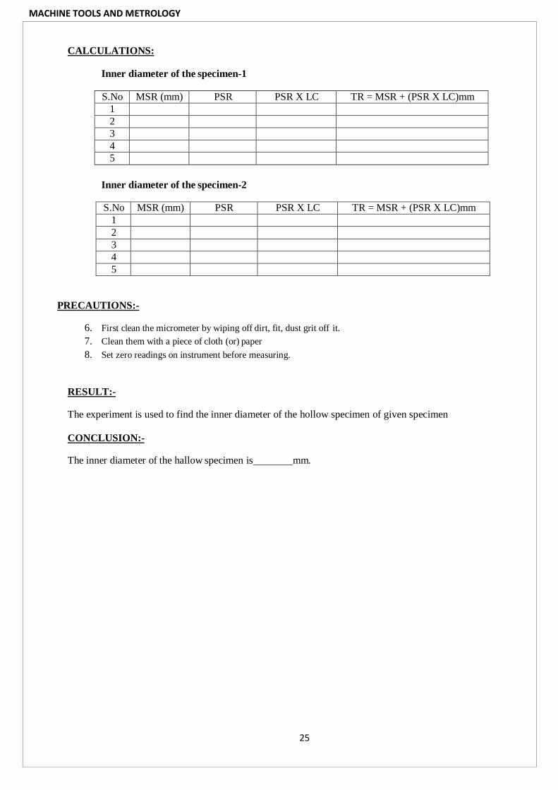
CALCULATIONS:
Inner diameter of the specimen-1
S.No MSR (mm) PSR PSR X LC TR = MSR + (PSR X LC)mm
1
2
3
4
5
Inner diameter of the specimen-2
S.No MSR (mm) PSR PSR X LC TR = MSR + (PSR X LC)mm
1
2
3
4
5
PRECAUTIONS:-
6. First clean the micrometer by wiping off dirt, fit, dust grit off it.
7. Clean them with a piece of cloth (or) paper
8. Set zero readings on instrument before measuring.
RESULT:-
The experiment is used to find the inner diameter of the hollow specimen of given specimen
CONCLUSION:-
The inner diameter of the hallow specimen is mm.

MACHINE TOOLS AND METROLOGY
26
WEEK – 10
EXPERIMENT10:-DIAL BORE INDICATOR
OBJECTIVE :-
To determine the bore diameter (Int. dice) of the given specimen
RESOURCES:-
Bore gauge, Anvils, Washers, and Specimens
THEORY:-
Bore gauge, is generally used to determine the bore diameter of components. Bore gauge consists of
following parts.
1. Dial gauge
2. Vertical column
3. Arrangement of anvil and washer
4. Movable spindle.
DIAL INDICATOR:-
This is used for measuring and checking linear measurement. These require less skills in their use than
other instruments such as micrometer, gauges etc, when dial indicator is used as essential part in
mechanism of any set up for measure purpose. It is referred as dial gauge. This gauge measures the
displacement of its plunger, on a circular dial by means of rotating point. A dial gauge consists of
graduated circular dial, pointer, contact point. Pointer gear train arrangement vessel clamp, revolution
counter. A dial gauge is show in fig. It works on the rack and pinion principle i.e., the reciprocating
motion is converted into linear motion. Gear teeth cut on it when the plunger reciprocates; it activates
a pinion which is attached to the pointer shaft. A gear train is used b/w plunger rack and pinion, to
magnify the movement of the plunger to the pointer. A revolution counter is used to count the number
of revolutions of the pointer.
Least count = 0.01mm

MACHINE TOOLS AND METROLOGY
27
PROCEDURE:-
5. Select the suitable anvil and washer to measure the dimension of given specimen.
6. Insert anvil and washer at the bottom of vertical column of bore gauge
7. Then insert the bore gauge and take the reading from dial indicator.
8. Subtract the dial indicator value from the sum of anvil and washer value, which gives the bore diameter
of given specimen.
9. Repeat same procedure to get the bore diameter at different positions of specimen.
SAMPLE CALCULATIONS:-
Least count (L.C) = 0.01mm
Anvil size = 45mm
Washer size = 45mm
Dial Indicator Reading = 14.5x0.01 = 0.145mm
Total Reading = (Anvil size + Washer size) – (Dial Indicator for Reading)
= (45+4.5) – (0.145) = 49.355mm.

MACHINE TOOLS AND METROLOGY
28
CALCULATION TOTAL READING:-
Bore diameter = (Anvil size + Washer size) – (Dial Indicator Reading).
Inner Diameter of the specimen-1.
S.No Anvil Size Washer size Dial Indicator Reading
TR = Anvil size + Washer size – Dial Indicator Reading(mm)
1
2
3
4
5
Inner Diameter of the specimen-2.
S.No Anvil Size Washer size Dial Indicator Reading
TR = Anvil size + Washer size – Dial Indicator Reading(mm)
1
2
3
4
5
PRECAUTIONS:-
10. First clean the micrometer, magnetic stand by wiping off dirt, fit, dust grit off it.
11. Clean them with a piece of cloth (or) paper
12. Set zero readings on instrument before measuring.
RESULT:-
The experiment has been conducted on bore gauge to determine the bore diameter of given specimen.
CONCLUSION:-
The bore diameter of the given specimen is mm.

MACHINE TOOLS AND METROLOGY
29
WEEK – 11
EXPERIMENT11:-SPIRIT LEVEL
OBJECTIVE:-
To chuck the flatness of given surface plate.
RESOURCES:-
Spirit level, surface plate
THEORY:-
Generally spirit level is used for leveling the machinery and other instruments. But spirit levels are
also used to measure the angles. It is also called precision level. It consist of glass tube and the glass
tube is filled with liquid and the bubble in the liquid always lies at the highest position of the tube. If
the tube is fitted through a small angle
If R – radius of tube
L – distance of bubble moved when spirit level is fitted to same angle
The angle is calculated as follows
L = Rθ, Θ = L/R
PROCEDURE:-
1. Keep the spirit level on the surface plate
2. Observe the bubble in the spirit level
3. If bubble is in the middle of spirit level than surface is flat.
4. If bubble is not in the middle of spirit level than surface is not flat
5. Repeat the same procedure at different places of surface plate.
FLATNESS Of The SPECIMEN.
S.No Horizontal Vertical Result
1
2
3
4
5

MACHINE TOOLS AND METROLOGY
30
PRECAUTIONS:-
6. First clean the spirit level stand by wiping off dirt, fit, dust grit off it.
7. Clean them with a piece of cloth (or) paper
RESULT:-
The experiment has been conducted on spirit level to check the flatness of given surface plate.
CONCLUSION:-
The given surface plate is flat/not flat.

MACHINE TOOLS AND METROLOGY
31
WEEK – 12
EXPERIMENT12: OPTICAL BEVEL PROTRACTOR
OBJECTIVE:-
To determine angle of given specimen
RESOURCES:-
Bevel protractor, specimen
THEORY:-
It is the simplest instrument for measuring the angle below the two faces of the component. Their important
components of protractor which is used to measure the angles are given below.
1) Vernier 2) Optical

MACHINE TOOLS AND METROLOGY
32
VERNIER BEVEL PROTRACTOR:-
It consists of a base plate to the main body and adjustable blade which is attached to the circular plate.
A vernier scale is provided on the main scale the adjustable scale is capable of rotating freely about
the centre of the main scale and it can be locked at any position by lock nut. It is capable of measuring
0 to 3600. The main scale on the disc is graduated in degrees of arc. The vernier scale has 12 divisions
on each side of centre zero.
Each division on the vernier scale
= 51 of arc which is the least count of vernier scale
The reading of vernier bevel protractor = M.S.R + (V.S.R x L.C.) mm.
OPTICAL BEVEL PROTRACTOR:-
A recent development of vernier bevel protractor is optical bevel protractor. In this instrument a glass
ole is divided at 101 of arc intervals throughout 3600 and this glass ole is fitted inside the main body. A
lens is fitted through which measurements are taken from the glass ole. With the help of the optical
bevel protractor it is possible to read 51 of arc i.e., L.C. of this instrument is 5-1
PROCEDURE:-
1 Place the adjustable blade on one side of the component.
2 Tight the blade using lock nut
3 Take the main scale reading
4 Take the vernier scale reading from vernier scale which is fixed on the main scale through lens.
CALCULATIONS:-
Angle of the specimen-1
S.No MSRo (mm)
VSR ‘ VSR X LC TR = MSR + (VSR X LC) mm
1
2
3
4
5
Angle of the specimen-2
S.No MSRo (mm)
VSR ‘ VSR X LC TR = MSR + (VSR X LC) mm
1
2
3
4
5

MACHINE TOOLS AND METROLOGY
33
PRECAUTIONS:-
1. Line of measurements and scale must coincide.
2. Measurement tips of caliber should parallel to the work piece centre line
3. Do not apply pressure on piece.
RESULT:-
The experiment is conducted an optical bevel protractor and angle of given specimen is determined
CONCLUSION:-
The angle of given specimen is

MACHINE TOOLS AND METROLOGY
34
WEEK – 13
Experiment.13 SINE BAR
OBJECTIVE:-
To measure the angle of the given component with sine bar
RESOURCES:-
SineBar , Slip Gauges, Work piece , Dial Indicator, Angle plate, C-Clamp.
THEORY:-
Sine Bar consists of a rectangular block of steel with ends machined to l- shaped recesses and
two perfectly ground cylinder pins of some diameter are fixed to the main body by means of
screws.
The plane containing the axes of rollers is perfectly parallel to the top surface of the main body of sine
bar ( this is an in-built feature). The sine bar is a simple instrument used for measuring or setting
angles generally below 45°. The measurement accuracy decrease if it is used for angles greater than
45 °.
Slip Gauges:-Slip gauges are rectangular blocks of steel having a cross-section of about 30 by 10mm.
These gauges are used to provide end standard of specific length by temporarily combining a number
of individual gauge by ‘wringing’, each representing a dimension (standard) into a single gauge bar.
Here the basic requirements are formation of a bar in reasonable cohesion between individual element
and its dimension truly within specific limits representing the desired nominal dimensions.
Accuracy: - Accuracy up to 10 millionth of an inch for flatness and parallelism can be obtained in
slip gauges.
Grading:- Grading according to accuracy and application.
AA - for master slip gauges.
A - for reference purpose.
B - for working slip gauges.
Grade 2 - Workshop grade
Grade 1 - Tool-room grade (More precise work)
Grade 0 - Inspection grade

MACHINE TOOLS AND METROLOGY
35
Calibration grade - Special grade (Prepared on chart)
PROCEDURE:-
1. The sine bar is made to rest on the surface plate with rollers contacting the datum (Surface plate.).
2. If the component on sine bar as shown in the figure and lock it in its position.
3. Lift on end (roller) of the sine bar and place a pack of slip gauges underneath the roller. The height
of the slip gauges (h) should be selected such that the top surface of component is parallel to the
datum plate (surface plate) .
4. The parallelism can be assessed by making the stylus of the dial indicator mounted on a dial gauge
stand. Contact the upper surfaces are perfectly parallel.
5. The pointer on the dial gauge shows the same reading throughout the travel of dial gauge stylus .I
the surfaces are not parallel then the height of slip gauge packing can be altered and procedure for
checking parallelism can be repeated.
6. Record the final height of slip gauge pack used for achieving parallelism.
7. Use the formulas sin ° h and elevate the angle .

MACHINE TOOLS AND METROLOGY
36
CALCULATIONS :-
A. Sin θ = h/L
θ = Sin-1 ( h/L )
θ =
B. Sin θ = (h1-h2 )/ L
θ = Sin-1 ( h1-h2) / L
θ =
h is Height of Slip Gauges, L is Length of rollers distance in Sin bar.
Steps to construct the required height up to the slip gauges
S no Diameter at
nose part
Dial gauge
reading
Error in dial
gauge reading
Total Reading
PRECAUTIONS:
8. Handle the slip gauges carefully.
9. Do not drop the slip gauges at any time .
10. This makes the slip gauges loose accuracy.
11. Slip gauges must be cleaned thoroughly with cleaning agents before the slip gauge.
Combination is made.
12. The surface plate also should be cleaned thoroughly before use.
RESULT:-
The unknown angle of component is

MACHINE TOOLS AND METROLOGY
37
WEEK – 14
EXPERIMENT14:-ALIGNMENT TEST ON LATHE MACHINE
OBJECTIVE :-
To perform alignment test on lathe
RESOURCES:-
Spirit level, gauge blocks, dial gauge
THEORY:-
The following are the alignment tests on lathe:-
1. LEVELING OF MACHINE
2. TRUE RUNNING OF MAIN SPINDLE
3. PARALLELISM OF MAIN SPINDLE TO SADDLE MOVEMENT
4. PARALLELISM OF TAILSTOCK GUIDE WAYS TO SADDLE MOVEMENT
5. PARALLELISM OF TAIL STOCK GUIDE WAYS TO CARRIAGE MOVEMENT
6. PARALLELISM OF MAIN SPINDLE TO CARRIAGE MOVEMENT
7. TRUE RUNNING OF HEAD STOCK CENTRE.
1. LEVELING OF MACHINE:-
It is essential that a machine tool should be installed truly horizontal and vertical plane and this
accuracy must be maintained. The level of machine base in longitudinal and transverse direction is
tested by spirit level or precision level. The spirit level is placed at a to measure the level.
2. TRUE RUNNING OF MAIN SPINDLE:-
The test mandrel is placed in the main spindle and test is conducted on the surface of mandrel. If dial
gauge shows any deviation in the reading then it is said that the main spindle is not running in the
proper way. If dial gauge should not deviate then it is said that the main spindle is running in the
proper way.
3. PARALLELISM OF MAIN SPINDLE TO SADDLE MOVEMENT:-
If the axis of spindle is not parallel to the saddle movement then it is not possible to get req.
dimension of work piece while doing the operation on lathe. The spindle is moved and the deviations
in the readings of dial gauge are noted.
4. PARALLELISM OF TAILSTOCK GUIDE WAYS TO SADDLE MOVEMENT:-
To check the parallelism of guide ways with the saddle movement in both vertical and horizontal
directions, the dial indicator is held on the spindle and block is moved simultaneously any deviation in
reading of dial gauge is noted if no deviation in the reading then tail stock guide ways is parallel to
saddle movement otherwise it is not parallel to saddle movement.
5. PARALLELISM OF TAIL STOCK GUIDE WAYS TO CARRIAGE MOVEMENT:-
To check the parallelism of guide ways with the carriage in both vertical and horizontal objections, a
block is placed on the guide ways of tail stock. The dial indicator is held on the carriage and block is
moved simultaneously any deviation in reading of dial gauge is noted.

MACHINE TOOLS AND METROLOGY
38
6. PARALLELISM OF MAIN SPINDLE TO CARRIAGE MOVEMENT:-
To check the parallelism of main spindle to carriage in both vertical and horizontal. The deviation is
observed the spindle is not parallel to the carriage.
7. TRUE RUNNING OF HEAD STOCK CENTRE:-
The test mandrel is placed in the head stock and test is conducted on the surface of carriage. The dial
gauge shows any deviations in the reading then the head stock is not running in proper way.
Lathe machine
MACHINE TOOLS AND METROLOGY
39
Viva Questions
1. What is a lathe?
Lathe is a machine, which removes the metal from a piece of work to the required shape
&size
2. What is the various operations can be performed on a lathe?
1. Turning 6. Thread cutting 11. Grooving
2. Facing 7. Drilling
3. Forming 8. Boring
4. Knurling 9. Recessing
5. Chamfering 10. Tapping
3. What are principle parts of the lathe?
Red, headstock, tailstock, carriage, cross slide, tool post
4. What are the types of headstock?
Back geared type, all geared type
5. State the various parts mounted on the carriage?
Saddle, compound rest, cross slide, tool post
6. What are the four types of tool post?
1. Single screw
2. Open side
3. Four bolt
4. Four way
7. What is an apron?
The integral part of several gears, levers clutches mounted with the saddle for moving the garage
along with lead screw while thread cutting
8. State any two specification of lathe?
1. The height of centers from the bed
2. The maximum length of the bed
9. List any four types of lathe?
1. Engine lathe
2. Bench lathe

MACHINE TOOLS AND METROLOGY
40
3. Tool room lathe
4. Semi automatic lathe
5. Automatic lathe
10. What is a semi-automatic lathe?
The lathe in which all the machining operations are performed automatically and loading and
unloading of work piece, coolant on or off is performed manually
11. What is copying lathe?
The tool of the lathe follows a template or master through a stylus or tracer
12. State the various feed mechanisms used for obtaining automatic feed?
1. Tumbler gear mechanism
2. Quick change gearbox
3. Tumbler gear- Quick change gearbox
4. Apron mechanism
13. List any four holding devices?
1. Chucks
2. Centers
3. Face plate
4. Angle plate
14. What are the different operations performed on the lathe?
Centering, straight turning, rough turning, finish turning, shoulder turning, facing, chamfering, etc
15. Define the term ‘Conicity’?
The ratio of the difference in diameters of tapers its length k= D-dl
d-smaller dia
D-bigger dia
l-length of the work piece
16. State any two specifications of capston lathe & turret lathe?
1. Number of spindle speed
2. Number of feeds for the turret or saddle
17. Compare the advantage of capston lathe & turret lathe?

MACHINE TOOLS AND METROLOGY
41
1. Heavier & larger work piece chucking can be done
2. More rigid hence it withstand heavy cuts
18. What is tooling?
Planning of operations sequence & preparation of turret or capston lathe are termed as tool-
layout or tooling
19. What are the three stage of a tool-layout?
1. Planning & scheduling
2. Detailed sketching of various machining operation sequence
3. Sketching the plan showing various tools
20. What are the different drives used in copying lathe?
1. Mechanical drives
2. Air drives
3. Hydraulic drives
21. What are the components that can be turned on a copying lathe?
1. Cam shaft
2. Crank shaft
3. Journal bearings
22. What is shaper?
The machine, which is having a reciprocating type of machine tool with a single point cutting tool,
used to produce flat surfaces called as Shapers
23. List any four important parts of a Shaper?
Table, Tool head, Ram, Cross rail
24. How the feed & depth of cut is given to the shaper?
Feed is given by rotating the down feed screws of tool head depth of cut is
given by rotating by raising or elevating the table
25. Mention any four-shaper specification?
1. Maximum length of stroke
2. Type of driving mechanism
3. Power of the motor
4. Speed &feed available

MACHINE TOOLS AND METROLOGY
42
26. How the planer differs from the shaper?
In planner-the work reciprocate while the tool is stationary In shaper-the tool reciprocate while the work is
stationary
27. State the use of planer?
The planer is used for machining heavy & large casting Ex. lathe bed ways, machine guide ways
28. List the various types of planners?
1. Double housing
2. Open side planer
3. Pit planer
4. Edge planer
5. Divided table planer
29. Name the various parts of a double housing planer?
1. Bed
2. Table
3. Columns
4. Cross rail
5. Tool head
30. Mention any four specification of planer?
1. Maximum length of the table
2. Total weight of the planer
3. Power of the motor
4. Range of speeds & feed available
5. Type of drive required
31. What is meant by drilling?
Drilling is the process of producing hole on the work piece by using a rotating cutter called drill
32. What is gang -drilling machine?
When a number of single spindles with essential speed & feed are mounted side by side on one
base and have common worktable is known as gang –drilling machine
33. Mention any four specification of drilling machine?

MACHINE TOOLS AND METROLOGY
43
1. Maximum size of the drill in mm that the machine can operate
2. Table size of maximum dimensions of a job can mount on a table in square meter
3. Maximum spindle travel in mm
4. Number of spindle speed & range of spindle speeds in r.p.m.
34. List any four machining operations that can be performed on a drilling machine?
1. Drilling
2. Counter sinking
3. Tapping
4. Trepanning
35. What are the different ways to mount the drilling tool?
1. Fitting directly in the spindle
2. By using a sleeve
3. By using a socket
4. By means of chucks
36. What is broaching?
Broaching is a process of machining a surface with a special multipoint cutting tool called
broach which has successfully higher cutting edges in a fixed path
37. Indicate any two specification of a broaching machine?
1. Maximum length of stroke in mm
2. Maximum force developed by the slide in tones
38. What are the advantages and limitation of broaching?
Advantages:
1. Roughing, semi finishing & finishing cuts are completed in one pass of the broach
2. Broaching can be used for either external or internal surface finish
Limitation:
1. High initial cost of the broach tool compare to other tools
2. Job work or batch work is not advisable due to the high tool cost.
39. What are the different operations that can be performed on a broaching machine?
1. Broaching splines
2. Broaching a key way

MACHINE TOOLS AND METROLOGY
44
40. What is boring?
Boring is a process of enlarging &locating previously drilled holes with a single point cutting tool
41. What are the application of boring?
The boring machine is designed for machining large &heavy work piece in mass production work
of engine frame, cylinder, machine housing etc
42. Specify the importance of jig boring machine?
a. A jig boring machine is a precision boring machine used for boring accurate holes at
proper center to center distances.
b. The machining accuracy of holes produce by this machine tool lies with in a range of
0.0025mm.
43. State the purpose of grinding?
1. To remove small amount of metal from work pieces & finish then to close tolerances.
2. To obtain the better surface finish.
44. What is the function of cutting fluids?
1. It is used to cool the cutting tool & the work piece.
2. It improves the surface finish as stated earlier.
3. It causes the chips to break up into small parts.
4. It protects the finish surface from corrosion.
5. It prevents the corrosion of work & machine.
45. What are the properties of cutting fluid?
1. High heat absorbing capacities.
2. It should have good lubricant properties.
3. High flash point.
4. It should be odourless.
5. It should be non-corrosive to work & tool.
46. What are causes of wear?
The tool is subjected to three important factors such as force, temperature and sliding action due to
relative motion between tool and the work piece. So the tool is wear easily.
47. What are the specifications of the milling machine?

MACHINE TOOLS AND METROLOGY
45
1. The table length &width.
2. Number of spindle speeds &feeds.
3. Power of driving motor.
48. Mention the various movements of universal milling machine table?
1. Vertical movement-through the knee.
2. Cross vise movement-through the saddle.
49. State any two comparisons between plain &universal milling machine?
In plain milling machine the table is provided with three movements, longitudinal, cross &
vertical. In universal milling machine in addition to these three movements, there is a forth
movement to the table. The table can be swiveled horizontally & can be fed at angles to the
milling machine spindle.
The universal milling machine is provided with auxiliaries such as dividing head, vertical milling
attachment, rotary table etc. Hence it is possible to make spiral, bevel gears, twist drills, reamers
etc on universal milling machine.
50. What are the cutter holding devices?
1. Arbors
2. Adaptors
3. Collets
51. List the various type of milling attachment?
1. Vertical milling
2. Universal milling
3. High speed milling
4. Rotary
5. Slotting
6. Rack milling
52. Write any ten nomenclature of plain milling cutter?
Body of cutter, cutting edge, face, fillet, gash, lead, land, outside dia, root dia, cutter angles
53. What are the advantages of milling process?
1. It does not require a backlash eliminator.
2. Mild surface does not have built up edge.
54. What are the down milling processes?

MACHINE TOOLS AND METROLOGY
46
1. Cutter with higher rake angle can be used. This reduces power requirements.
2. Cutter wear is less because chip thickness is maximum at the start of cut.
55. List out the various milling operations?
1. Plain or slab milling.
2. Face milling.
3. Angular milling.
4. Gang milling.
5. End milling.
6. Gear cutting.
56. What does term indexing mean?
Indexing is the process of dividing the periphery of a job into equal number of divisions.
57. What are the three types dividing heads?
1. Plain or simple.
2. Universal.
3. Optical.
58. What is cam milling?
Cam milling is operation of producing cams in the milling machine by the use universal
dividing head &a vertical milling attachment.
59. What are the different types of thread milling?
1. Thread milling by single form cutter.
2. Thread milling by multi form cutter.
60. What are the other forming methods for manufacturing gears?
1. Gear cutting by single point form tool.
2. Gear cutting by shear speed shaping process.
3. Gear broaching.
4. Template method.
5. Gear milling using a formed end mill.
61. List the gear generating process?
1. Gear shaping process.
2. Gear planning process.

MACHINE TOOLS AND METROLOGY
47
3. Gear hobbing process.
62. Mention the applications of gear shaping process?
1. Gear shaping used for generating both internal & external spur gears.
2. Helical gears can also be generated using special attachments.
63. What are the limitations of gear hobbing?
1. Internal gears cannot be generated.
2. Hobbing process cannot be applied very near to shoulders.
64. What are the advantages of gear planning process?
1. Any given model can be cut using a single cutter.
2. It is a simple flexible &accurate method of generating gears.
65. List the various gear finishing processes?
1. Gear shaving.
2. Gear burnishing.
3. Gear grinding.
4. Gear lapping.
66. Mention the advantages &limitations of gear shaving process?
Advantage:
The process can be used for both internal & external gears.
Limitations:
This process is only applicable to unhardened gears.
67. What are the purposes of gear grinding process?
1. To improve the surface finish of teeth.
2. To increase the accuracy of the teeth.
68. What is gear lapping?
Gear lapping is also employed for hardened gear teeth by an abrasive action.
69. Explain the cutting shaping process?
The required shape of metal is obtained by removing the Unwanted material from the work
piece in the form of chips is called cutting shaping. Ex: turning, drilling, milling, boring, etc
70. Mention the various parts of single point cutting tool?
1. Shank

MACHINE TOOLS AND METROLOGY
48
2. Face
3. Flank
4. Base
5. Nose
6. Cutting edge
71. What is tool signature?
The various angles of tools are mentioned in a numerical number in particular order. that
order is known as tool signature.
72. What is effect of back rake angle &mention the types?
Back rake angle of tool is increases the strength of cutting tool& cutting action. It can be
classified in to two types
i) Positive rake angle ii)
Negative rake angle
73. What is side rake angle & mention its effects?
The angle between the tool face & the line parallel to the base of the tool. it is used to control chip
flow
74. What are all the conditions for using positive rake angle?
1. To machine the work hardened materials
2. To turn the long shaft of small dia
75. When will the negative rake angles be used?
1. To machine high strength alloys
2. The feed rates are high
76. Define orthogonal & oblique cutting?
Orthogonal cutting:
The cutting edge of tool is perpendicular to the work piece axis.
Oblique cutting:
The cutting edge is inclined at an acute angle with normal to the cutting velocity vector is called
oblique cutting process
77. What is cutting force?
The sheared material begins to flow along the cutting tool face in the form of small pieces.
The compressive force applied to form the chip is called cutting force

MACHINE TOOLS AND METROLOGY
49
78. What is chip thickness ratio?
The ratio of chip thickness before cutting to chip thickness after cutting is called chip thickness ratio.
79. What are the purposes of chip breakers?
The chip breakers are used to break the chips in to small pieces for the removal, safety & to
prevent to machine & work
80. Define machinability of metal?
Machinability is defined as the ease with which the material can be satisfactorily machine.
81. What are the factors affecting the machinability?
1. Chemical composition of work piece material.
2. Microstructure of work piece material
82. What is machinability index?
It is the comparison of machinability different material to standard material. US material
standards for 100% machinability are sae1112 hot rolled steel.
Machinability index I=Cutting speed of metal investicatedfor 20 minutes tool life
Cutting speed of standard steel for 20 minutes tool life
83. How tool life is defined?
Tool life is defined as time elapsed between two consecutive tool resharpening. During this
period tools serves effectively and efficiently.
84. What are the factors affecting tool life?
1. Cutting speed
2. Feed & depth of cut
3. Tool geometry
4. Tool material
85. Express the Tailor’s tool life equation?
Tailors tool life equation:
VTn=C
V=Cutting speed in m/min
T=Tool life in minutes
C=Constant
n=Index depends upon tool & work