machine vision systems - home | george mason …zduric/cs482/slides/machinevision.pdf · machine...
TRANSCRIPT

Machine vision systems - 1 Zoran Duric cs499
Machine vision systems
◆ Problem definition
◆ Image acquisition
◆ Image segmentation
◆ Connected component analysis
Machine vision systems - 2 Zoran Duric cs499
Problem definition
◆ Design a vision system to “see” a “flat” world◆ Page of text
◆ Side panel of a truck
◆ X-ray image of separated potatoes
◆ General approach to recognition/inspection◆ Acquire gray scale image using camera
◆ Reduce to black and white image - black objects on white background
◆ Find individual black objects and measure their properties
◆ Compare those properties to object models

Machine vision systems - 3 Zoran Duric cs499
Digital image acquisition
◆ Camera, such as a scanner, measures intensity of reflected light over a regularly spaced grid of positions
◆ individual grid elements are called pixels
◆ typical grid from a TV camera is 512 x 480 pixels created by a process called sampling.
◆ scanner can produce much higher resolution images
◆ measurements at pixels are called intensities or gray levels
◆ typical camera provides 6-8 bits of intensity per pixel created by a process called quantization.
This is a printed page
We want to read thecharacters
Machine vision systems - 4 Zoran Duric cs499
Image segmentation
◆ How do we know which groups of pixels in a digital image correspond to the objects to be analyzed?◆ objects may be uniformly darker or brighter than the
background against which they appear◆ black characters imaged against the white background of a
page
◆ bright, dense potatoes imaged against a background that is transparent to X-rays

Machine vision systems - 5 Zoran Duric cs499
Image segmentation◆ Ideally, object pixels would be black (0 intensity)
and background pixels white (maximum intensity)
◆ But this rarely happens◆ pixels overlap regions from both the object and the
background, yielding intensities between pure black and white - edge blur
◆ cameras introduce “noise” during imaging -measurement “noise”
◆ potatoes have non-uniform “thickness”, giving variations in brightness in X-ray - model “noise”
Machine vision systems - 6 Zoran Duric cs499

Machine vision systems - 7 Zoran Duric cs499
Image segmentation by thresholding
◆ But if the objects and background occupy different ranges of gray levels, we can “mark” the object pixels by a process calledthresholding:◆ Let F(i,j) be the original, gray level image
◆ B(i,j) is a binary image (pixels are either 0 or 1) created by thresholding F(i,j)
◆ B(i,j) = 1 if F(i,j) < t
◆ B(i,j) = 0 if F(i,j) >= t
◆ We will assume that the 1’s are the object pixels and the 0’s are the background pixels
Machine vision systems - 8 Zoran Duric cs499
Thresholding◆ How do we choose the threshold t?
◆ Histogram (h) - gray level frequency distribution of the gray level image F.◆ hF(g) = number of pixels in F whose gray level is g
◆ HF(g) = number of pixels in F whose gray level is <=g
intensity, g
h(g)
peak peak
valley
observed histogram
ideal h

Machine vision systems - 9 Zoran Duric cs499
Thresholding
◆ P-tile method◆ in some applications we know approximately what
percentage, p, of the pixels in the image come from objects
◆ might have one potato in the image, or one character.
◆ HF can be used to find the gray level, g, such that ~p% of the pixels have intensity <= g
◆ Then, we can examine hF in the neighborhood of g to find a good threshold (low valley point)
Machine vision systems - 10 Zoran Duric cs499
Thresholding
◆ Peak and valley method◆ Find the two most prominent peaks of h
◆ g is a peak if hF(g) > hF(g ± ∆g), ∆g = 1, ..., k
◆ Let g1 and g2 be the two highest peaks, with g1 < g2
◆ Find the deepest valley, g, between g1 and g2
◆ g is the valley if hF(g) <= hF(g’) , g,g’ in [g1, g2]
◆ Use g as the threshold

Machine vision systems - 11 Zoran Duric cs499
Triangle algorithm◆ A line is constructed between the
maximum of the histogram at brightnessbmax and the lowest value bmin = (p=0)% in the image.
◆ The distance d between the line and the histogram h[b] is computed for all values of b from b = bmin to b = bmax.
◆ The brightness value bo where the distance between h[bo] and the line is maximal is the threshold value.
◆ This technique is particularly effective when the object pixels produce a weak peak in the histogram.
Machine vision systems - 12 Zoran Duric cs499
Thresholding◆ Hand selection
◆ select a threshold by hand at the beginning of the day
◆ use that threshold all day long!
◆ Many threshold selection methods in the literature◆ Probabilistic methods
◆ make parametric assumptions about object and background intensity distributions and then derive “optimal” thresholds
◆ Structural methods◆ Evaluate a range of thresholds wrt properties of resulting
binary images
◆ one with straightest edges, most easily recognized objects, etc.
◆ Local thresholding◆ apply thresholding methods to image windows
Machine vision systems - 13 Zoran Duric cs499
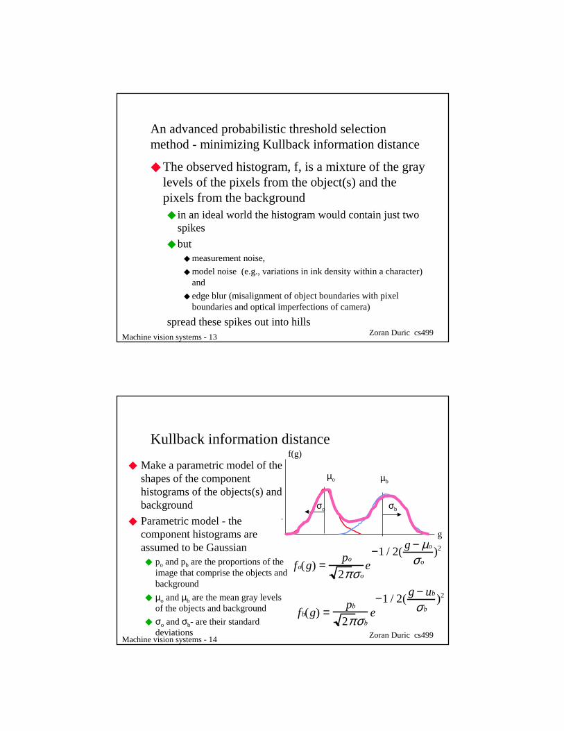
An advanced probabilistic threshold selection method - minimizing Kullback information distance
◆ The observed histogram, f, is a mixture of the gray levels of the pixels from the object(s) and the pixels from the background◆ in an ideal world the histogram would contain just two
spikes
◆ but ◆ measurement noise,
◆ model noise (e.g., variations in ink density within a character) and
◆ edge blur (misalignment of object boundaries with pixel boundaries and optical imperfections of camera)
spread these spikes out into hills
Machine vision systems - 14 Zoran Duric cs499
Kullback information distance
◆ Make a parametric model of the shapes of the component histograms of the objects(s) and background
◆ Parametric model - the component histograms are assumed to be Gaussian
◆ po and pb are the proportions of the image that comprise the objects and background
◆ µo and µb are the mean gray levels of the objects and background
◆ σo and σb- are their standard deviations
fo(g) =po
2πσoe
−1 / 2(g − µo
σo)2
o
fb(g) =pb
2π σbe−1 / 2(
g − ub
σb)2
g
f(g)
µo µb
σo σb

Machine vision systems - 15 Zoran Duric cs499
Kullback information distance
◆ Now, if we hypothesize a threshold, t, then all of these unknown parameters can be approximated from the image histogram.
◆ Let f(g) be the observed and normalized histogram◆ f(g) = percentage of pixels from image having gray
level gpo(t) = f (g)
g= 0
t
∑
µo(t) = f (g)gg= 0
t
∑ µb(t) = f (g)gg= t +1
max
∑
pb(t) = 1− p0(t)
Machine vision systems - 16 Zoran Duric cs499
Kullback information distance
◆ So, for any hypothesized t, we can “predict” what the total normalized image histogram should be if our model (mixture of two Gaussians) is correct.◆ Pt(g) = pofo(g) + pbfb(g)
◆ The total normalized image histogram is observed to be f(g)
◆ So, the question reduces to:◆ determine a suitable way to measure the similarity of P
and f
◆ then search for the t that gives the highest similarity

Machine vision systems - 17 Zoran Duric cs499
Kullback information distance
◆ A suitable similarity measure is the Kullbackdirected divergence, defined as
◆ If Pt matches f exactly, then each term of the sum is 0 and K(t) takes on its minimal value of 0
◆ Gray levels where Pt and f disagree are penalized by the log term, weighted by the importance of that gray level (f(g))
])(
)(log[)()(
max
0 gP
gfgftK
tg∑
=
−=
Machine vision systems - 18 Zoran Duric cs499
An alternative - minimize probability of error◆ Using the same mixture model, we can search for
the t that minimizes the predicted probability of error during thresholding
◆ Two types of errors◆ background points that are marked as object points.
These are points from the background that are darker than the threshold
◆ object points that are marked as background points. These are points from the object that are brighter than the threshold

Machine vision systems - 19 Zoran Duric cs499
An alternative - mimimizeprobability of error
◆ For each “reasonable” threshold
◆ compute the parameters of the two Gaussians and the proportions
◆ compute the two probability of errors
◆ Find the threshold that gives
◆ minimal overall error
◆ most equal errors
t
eo(t) = po fo(g)g= t +1
max
∑
fo
eb(t) = pb fb(g)g =0
t
∑
fb
Machine vision systems - 20 Zoran Duric cs499
Machine vision systems - 21 Zoran Duric cs499
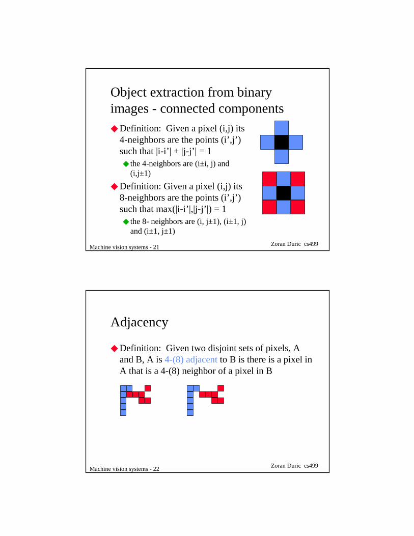
Object extraction from binary images - connected components◆ Definition: Given a pixel (i,j) its
4-neighbors are the points (i’,j’) such that |i-i’| + |j-j’| = 1◆ the 4-neighbors are (i±i, j) and
(i,j±1)
◆ Definition: Given a pixel (i,j) its 8-neighbors are the points (i’,j’) such that max(|i-i’|,|j-j’|) = 1◆ the 8- neighbors are (i, j±1), (i±1, j)
and (i±1, j±1)
Machine vision systems - 22 Zoran Duric cs499
Adjacency
◆ Definition: Given two disjoint sets of pixels, A and B, A is 4-(8) adjacent to B is there is a pixel in A that is a 4-(8) neighbor of a pixel in B
Machine vision systems - 23 Zoran Duric cs499
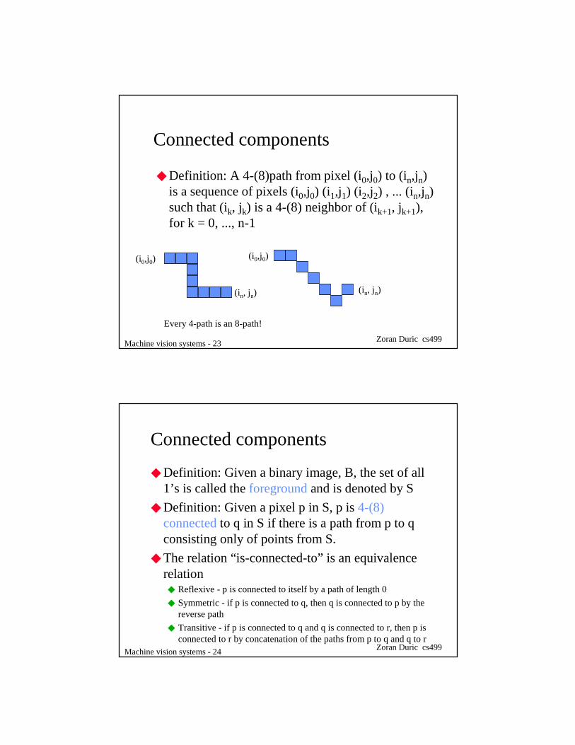
Connected components
◆ Definition: A 4-(8)path from pixel (i0,j0) to (in,jn) is a sequence of pixels (i0,j0) (i1,j1) (i2,j2) , ... (in,jn) such that (ik, jk) is a 4-(8) neighbor of (ik+1, jk+1), for k = 0, ..., n-1
(i0,j0)
(in, jn)
(i0,j0)
(in, jn)
Every 4-path is an 8-path!
Machine vision systems - 24 Zoran Duric cs499
Connected components
◆ Definition: Given a binary image, B, the set of all 1’s is called the foregroundand is denoted by S
◆ Definition: Given a pixel p in S, p is 4-(8) connectedto q in S if there is a path from p to q consisting only of points from S.
◆ The relation “is-connected-to” is an equivalence relation
◆ Reflexive - p is connected to itself by a path of length 0
◆ Symmetric - if p is connected to q, then q is connected to p by the reverse path
◆ Transitive - if p is connected to q and q is connected to r, then p is connected to r by concatenation of the paths from p to q and q to r

Machine vision systems - 25 Zoran Duric cs499
Connected components◆ Since the “is-connected-to” relation is an
equivalence relation, it partitions the set S into a set of equivalence classes or components◆ these are called connected components
◆ Definition: SS is the complement of S - it is the set of all pixels in B whose value is 0◆◆ SS can also be partitioned into a set of connected
components
◆ Regard the image as being surrounded by a frame of 0’s
◆ The component(s) ofSS that are adjacent to this frame is called the backgroundof B.
◆ All other components of SS are called holes
Machine vision systems - 26 Zoran Duric cs499
Examples - Black = 1, Green = 0
How many 4- (8) components of S?What is the background?Which are the 4- (8) holes?

Machine vision systems - 27 Zoran Duric cs499
Background and foreground connectivity◆ Use opposite connectivity for the foreground and
the background◆ 4-foreground, 8-background: 4 single pixel objects and
no holes
◆ 4-background, 8-foreground: one 4 pixel object containing a 1 pixel hole
Machine vision systems - 28 Zoran Duric cs499
Boundaries◆ The boundary of S is the set of all pixels of S that
have 4-neighbors in SS. The boundary set is denoted as S’.
◆ The interior is the set of pixels of S that are not in its boundary: S-S’
◆ Definition: Region T surrounds region R (or R is inside T) if any 4-path from any point of R to the background intersects T
◆ Theorem: If R and T are two adjacent components, then either R surrounds T or T surrounds R.

Machine vision systems - 29 Zoran Duric cs499
Examples
A
B
AA
AA
AA
AA
AA
BB
AA
A B
BB
Even levels are components of 0’sThe background is at level 0Odd levels are components of 1’s
Machine vision systems - 30 Zoran Duric cs499
Component labeling
◆ Given: Binary image B
◆ Produce: An image in which all of the pixels in each connected component are given a unique label.
◆ Solution 1: Recursive, depth first labeling◆ Scan the binary image from top to bottom, left to right
until encountering a 1 (0).
◆ Change that pixel to the next unused component label
◆ Recursively visit all (8,4) neighbors of this pixel that are 1’s (0’s) and mark them with the new label
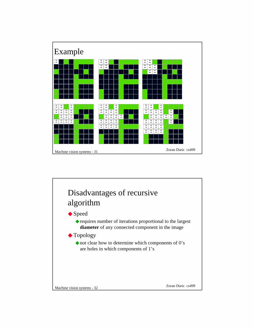
Machine vision systems - 31 Zoran Duric cs499
Example
Machine vision systems - 32 Zoran Duric cs499
Disadvantages of recursive algorithm◆ Speed
◆ requires number of iterations proportional to the largest diameter of any connected component in the image
◆ Topology◆ not clear how to determine which components of 0’s
are holes in which components of 1’s

Machine vision systems - 33 Zoran Duric cs499
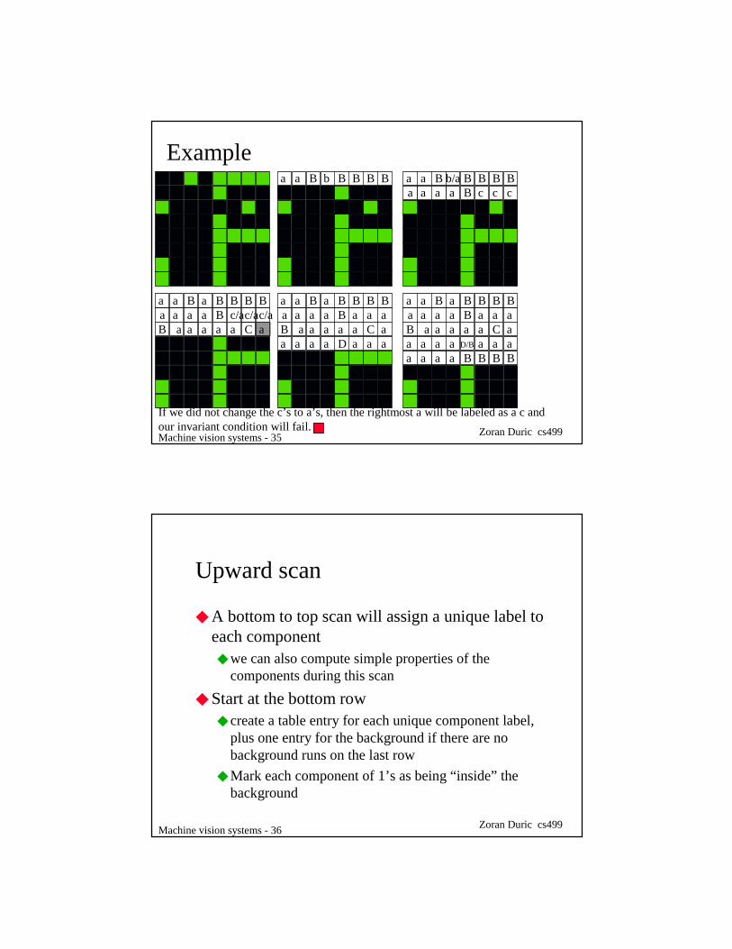
Solution 2 - row scanning up and down◆ Start at the top row of the image
◆ partition that row into runs of 0’s and 1’s◆ each run of 0’s is part of the background, and is given the special
background label◆ each run of 1’s is given a unique component label
◆ For all subsequent rows◆ partition into runs◆ if a run of 1’s (0’s) has no run of 1’s(0’s) directly above it, then it is
potentially a new component and is given a new label◆ if a run of 1’s (0’s) overlaps one or more runs on the previous row
give it the minimum label of those runs◆ Let a be that minimal label and let {ci} be the labels of all other
adjacent runs in previous row. Relabel all runs on previous row having labels in {ci} with a
Machine vision systems - 34 Zoran Duric cs499
Local relabeling
◆ What is the point of the last step?◆ We want the following invariant condition to hold after
each row of the image is processed on the downward scan: The label assigned to the runs in the last row processed in any connected component is the minimumlabel of any run belonging to that component in the previous rows.
◆ Note that this only applies to the connectivity of pixels in that part of B already processed. There may be subsequent merging of components in later rows
Machine vision systems - 35 Zoran Duric cs499
Examplea a B b BBBB a a B b/a BBBB
a a a a B c c c
a a B a BBBBa a a a B c/ac/ac/aB a a a a a C a
a a B a BBBBa a a a B a a aB a a a a a C aa a a a D a a a
a a B a BBBBa a a a B a a aB a a a a a C aa a a a D/B a a aa a a a B B B B
If we did not change the c’s to a’s, then the rightmost a will be labeled as a c andour invariant condition will fail.
Machine vision systems - 36 Zoran Duric cs499
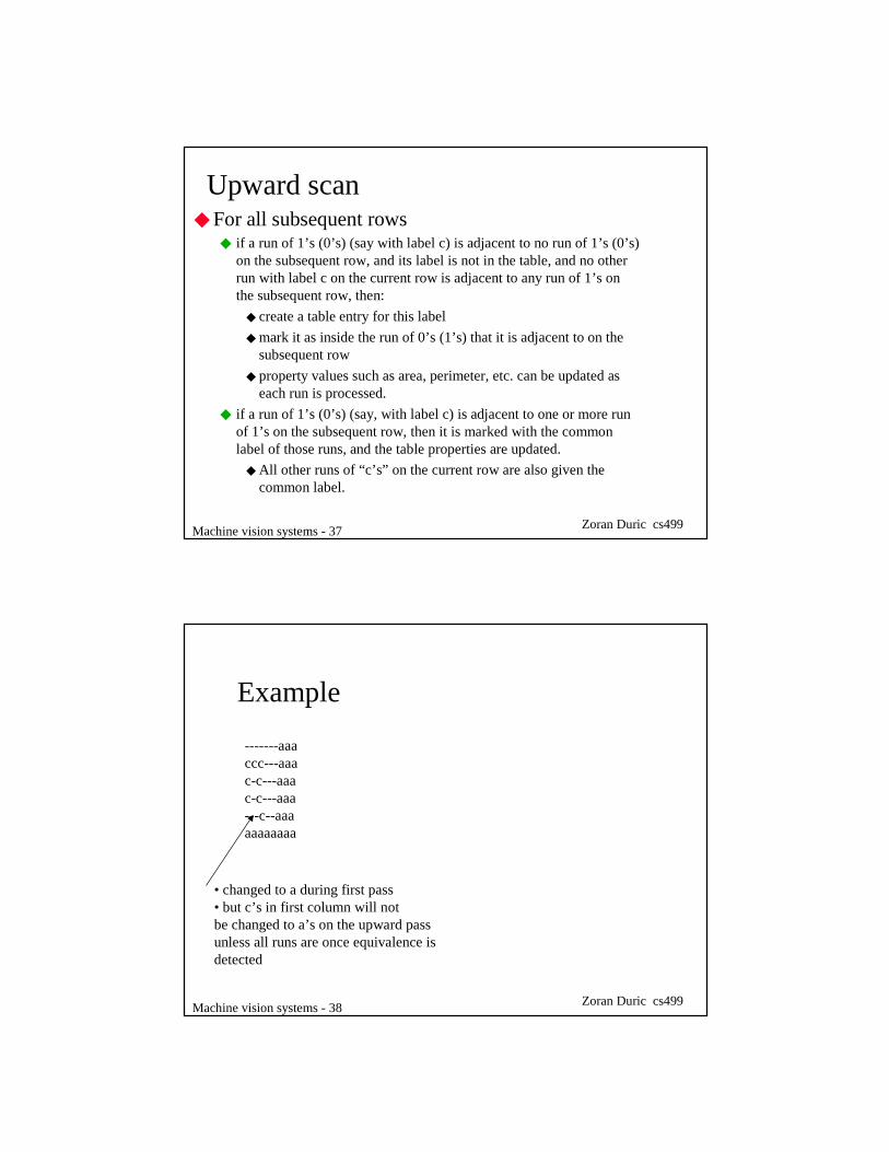
Upward scan
◆ A bottom to top scan will assign a unique label to each component◆ we can also compute simple properties of the
components during this scan
◆ Start at the bottom row◆ create a table entry for each unique component label,
plus one entry for the background if there are no background runs on the last row
◆ Mark each component of 1’s as being “inside” the background
Machine vision systems - 37 Zoran Duric cs499
Upward scan◆ For all subsequent rows
◆ if a run of 1’s (0’s) (say with label c) is adjacent to no run of 1’s (0’s) on the subsequent row, and its label is not in the table, and no other run with label c on the current row is adjacent to any run of 1’s on the subsequent row, then:
◆ create a table entry for this label
◆ mark it as inside the run of 0’s (1’s) that it is adjacent to on the subsequent row
◆ property values such as area, perimeter, etc. can be updated as each run is processed.
◆ if a run of 1’s (0’s) (say, with label c) is adjacent to one or more run of 1’s on the subsequent row, then it is marked with the common label of those runs, and the table properties are updated.
◆ All other runs of “c’s” on the current row are also given the common label.
Machine vision systems - 38 Zoran Duric cs499
Example
-------aaaccc---aaac-c---aaac-c---aaa---c--aaaaaaaaaaa
• changed to a during first pass• but c’s in first column will notbe changed to a’s on the upward passunless all runs are once equivalence is detected
Machine vision systems - 39 Zoran Duric cs499
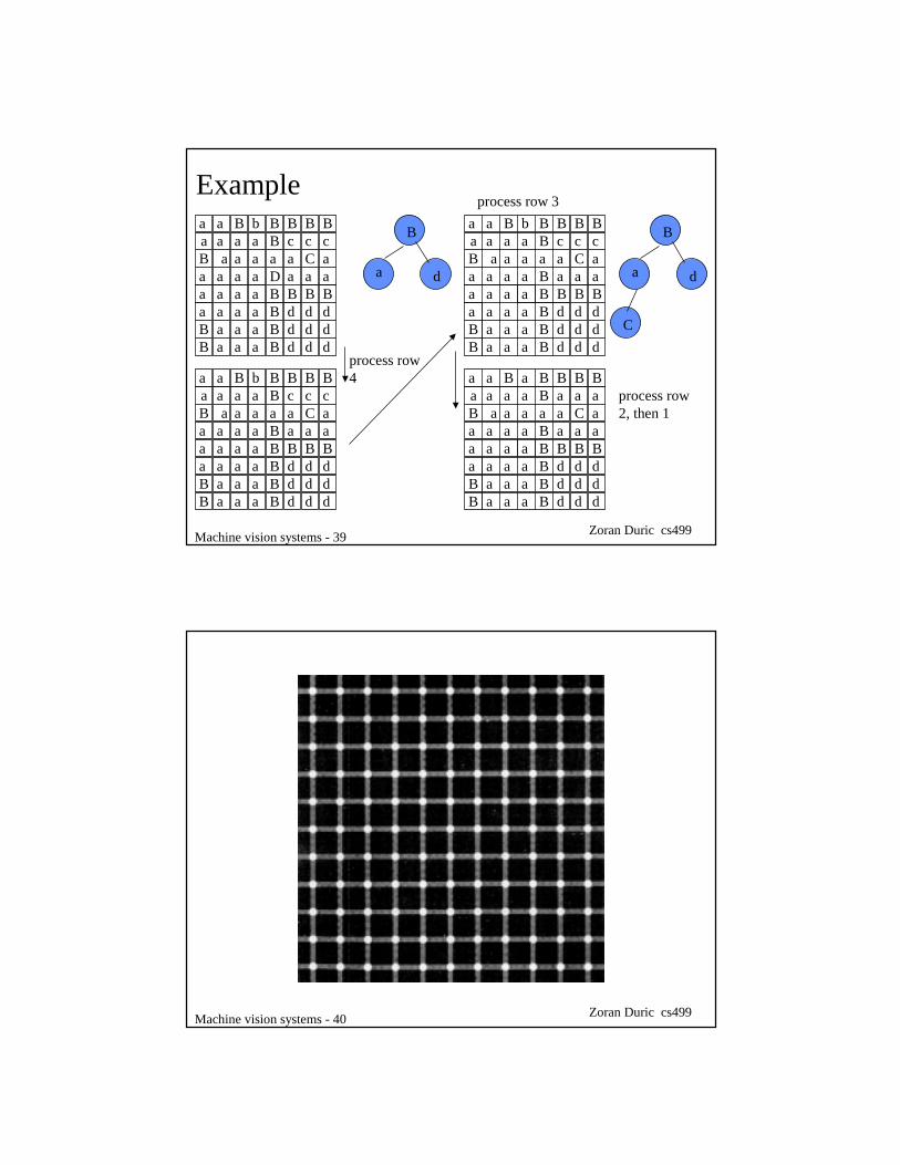
Examplea a B b BBBBa a a a B c c cB a a a a a C aa a a a D a a aa a a a B B B Ba a a a
a a aa a a
BB
BBB
d d dd d dd d d
B
a d
a a B b BBBBa a a a B c c cB a a a a a C aa a a a B a a aa a a a B B B Ba a a a
a a aa a a
BB
BBB
d d dd d dd d d
a a B b BBBBa a a a B c c cB a a a a a C aa a a a B a a aa a a a B B B Ba a a a
a a aa a a
BB
BBB
d d dd d dd d d
process row4
B
a d
C
process row 3
a a B a BBBBa a a a B a a aB a a a a a C aa a a a B a a aa a a a B B B Ba a a a
a a aa a a
BB
BBB
d d dd d dd d d
process row2, then 1
Machine vision systems - 40 Zoran Duric cs499

Machine vision systems - 41 Zoran Duric cs499
Properties
◆ Our goal is to recognize each connected component as one of a set of known objects◆ letters of the alphabet
◆ good potatoes versus bad potatoes
◆ We need to associate measurements, or properties, with each connected component that we can compare against expected properties of different object types.
Machine vision systems - 42 Zoran Duric cs499
Properties
◆ Area
◆ Perimeter
◆ Compactness: P2/A◆ smallest for a circle: 4π2r2/πr2 = 4π◆ higher for elongated objects
◆ Properties of holes◆ number of holes
◆ their sizes, compactness, etc.

Machine vision systems - 43 Zoran Duric cs499
How do we compute the perimeter of a connected component?
1. Count the number of pixels in the component adjacent to 0’s
◆ perimeter of black square would be 1
◆ but perimeter of gray square, which has 4x the area, would be 4
◆ but perimeter should go up assqrt of area
2. Count the number of 0’s adjacent to the component
◆ works for the black and gray squares, but fails for
the red dumbbell
Machine vision systems - 44 Zoran Duric cs499
How do we compute the perimeter of a connected component?
3) Count the number of sides of pixels in the component adjacent to 0’s
◆ these are the cracks between the pixels
◆ clockwise traversal of these cracks is called a crack code
◆ perimeter of black is 4, gray is 8 and red is 8
◆ What effect does rotation have on the value of a perimeter of the digitization of a simple shape?
◆ rotation can lead to large changes in the perimeter and the area!

Machine vision systems - 45 Zoran Duric cs499
A better (and universal)set of features
◆ An “ideal” set of features should be independent of◆ the position of the connected component
◆ the orientation of the connected component
◆ the size of the connected component◆ ignoring the fact that as we “zoom in” on a shape we tend to
see more detail
◆ These problems are solved by features called moments
Machine vision systems - 46 Zoran Duric cs499
Central moments
◆ Let S be a connected component in a binary image◆ generally, S can be any subset of pixels, but for our
application the subsets of interest are the connected components
◆ The (j,k)’th moment of S is defined to be
∑∈
=Syx
kjjk yxSM
),(
)(

Machine vision systems - 47 Zoran Duric cs499
Central moments
◆ M00 = the area of the connected component
◆ The center of gravity of S can be expressed as
SyxSMSyxSyx
∑∑∈∈
===),(),(
0000 1)(
S
y
SM
SMy
S
x
SM
SMx
∑
∑
==
==
)(
)(
)(
)(
00
01
00
10
Machine vision systems - 48 Zoran Duric cs499
Central moments
◆ Using the center of gravity, we can define the central (j,k)’th moment of S as
◆ If the component S is translated, this means that we have added some numbers (a,b) to the coordinates of each pixel in S◆ for example, if a = 0 and b = -1, then we have shifted
the component up one pixel
kjjk yyxx )()( −−= ∑µ
Machine vision systems - 49 Zoran Duric cs499
Central moments
◆ Central moments are not affected by translations of S. Let S’={(x’, y’):x’=x+a, y’=y+b, (x,y) in S}◆ The center of gravity of S’ is the c.o.g. of S shifted by
(a,b)
◆ The central moments of S’ are the same as those of S
axS
a
S
x
S
ax
S
xSx +=+=
+== ∑∑∑∑ )(
’
’)’(
)()()(
]))([(]))([(
))’(’())’(’()’(
Syyxx
bSybyaSxax
SyySxxS
jkkj
kj
kjjk
µ
µ
=−−=
+−++−+=
−−=
∑∑
∑
Machine vision systems - 50 Zoran Duric cs499
Central moments◆ The standard deviations of the x and y coordinates of S can
also be obtained from central moments:
◆ We can then created a set of normalized coordinates of S that we can use to generate moments unchanged by translation and scale changes
S
S
y
x
02
20
µσ
µσ
=
=
x
xxx
σ−=
~
y
yyy
σ−=
~

Machine vision systems - 51 Zoran Duric cs499
Normalized central moments◆ The means of these new variables are 0, and their standard
deviations are 1. If we define the normalized moments; mjk as follows
◆ then these moments are not changed by any scaling or translation of S
◆ Let S* = {(x*,y*): x* = ax + b, y* = ay + c, (x,y) in S}◆ if b and c are 0, then we have scaled S by a
◆ if a is 0, then we have translated S by (b,c)
00
~~
M
yxm
kj
jk∑=
Machine vision systems - 52 Zoran Duric cs499
Normalized central moments
◆ Details of the proof are simple.
)(
))(
))(()(
)(
))(((
)*)(
*)(*()
*)(*)(*
(
*)(
Sm
S
Sa
Syya
Sa
Sxxa
S
SSyy
SSxx
Sm
jk
ky
k
kk
jx
j
jj
k
y
j
xjk
=
−−
=
−−
=
∑
∑
σσ
σσ
Machine vision systems - 53 Zoran Duric cs499
Shortcomings of our machine vision system◆ Object detection
◆ thresholding will not extract intact objects in complex images
◆ shading variations on object surfaces
◆ texture
◆ advanced segmentation methods◆ edge detection - locate boundaries between objects and
background, between objects and objects
◆ region analysis - find homogeneous regions; small combinations might correspond to objects.
Machine vision systems - 54 Zoran Duric cs499
Shortcomings of our machine vision system
◆ Occlusion◆ What if one object is partially hidden by another?
◆ properties of the partially obscured, or occluded, object will not match the properties of the class model
◆ Correlation - directly compare image of the “ideal” objects against real images
◆ in correct overlap position, matching score will be high
◆ Represent objects as collection of local features such as corners of a rectangular shape
◆ locate the local features in the image
◆ find combinations of local features that are configured consistently with objects

Machine vision systems - 55 Zoran Duric cs499
Shortcomings of our machine vision system◆ Recognition of three dimensional objects
◆ the shape of the image of a three dimensional object depends on the viewpoint from which it is seen
◆ Model a three dimensional object as a large collection of view-dependent models
◆ Model the three dimensional geometry of the object and mathematically relate it to its possible images◆ mathematical models of image geometry
◆ mathematical models for recognizing three dimensional structures from two dimensional images
Machine vision systems - 56 Zoran Duric cs499
Shortcomings of our machine vision system◆ Articulated objects
◆ pliers
◆ derricks
◆ Deformable objects◆ faces
◆ jello
◆ Amorphous objects◆ fire
◆ water
Machine vision systems - 57 Zoran Duric cs499
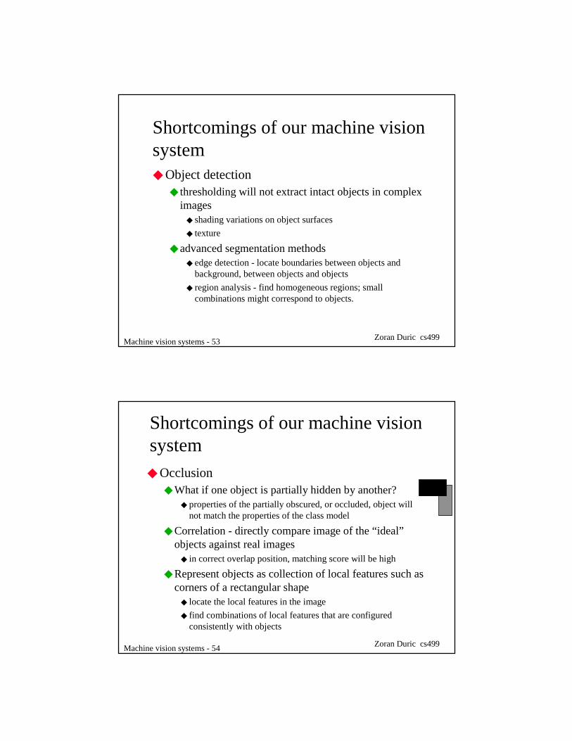
Agenda◆ Advanced segmentation methods◆ edge detection
◆ region recovery
◆ Occlusion in 2-D◆ correlation
◆ clustering
◆ Articulations in 2-D
◆ Three dimensional object recognition◆ modeling 3-D shape
◆ recognizing 3-D objects from 2-D images
◆ recognizing 3-D objects from 3-D images◆ stereo
◆ structured light range sensors
Machine vision systems - 58 Zoran Duric cs499