machines and tools transmit or convert motion, force,...
TRANSCRIPT

Machines and Tools
Machines and tools transmit or convert motion, force, energy...

Machines or Mechanisms 1. Mechanisms help extend human capability by
creating some desired output or motion.
2. A mechanism takes an input motion or force and creates a desired output motion or force.
MECHANISM Motion or force
Motion or force

Types of Motion
• Common types of motion: – Linear – Rotational – Oscillatory
All these have applications in robotics
Energy: Ability to do work
Work = Force * Distance
Force: A Push or a Pull
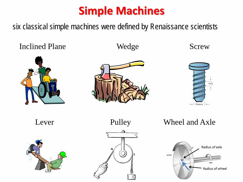
Simple Machines
Lever Pulley Wheel and Axle
Wedge Screw Inclined Plane
six classical simple machines were defined by Renaissance scientists
A simple machine uses a single applied /input/effort force to do work against a single load/resistance force. Work done on the load equals work done by the applied force (ignoring frictional losses). The machine can increase the amount of the output force, at the cost of a proportional decrease in the distance moved by the load. The ratio of the output to the input (applied, effort) force is called the mechanical advantage.

Simple machines can be regarded as the elementary "building blocks" of which all more complicated machines ("compound machines") are composed. For example, wheels, levers, and pulleys are all used in the mechanism of a bicycle. The mechanical advantage of a compound machine is just the product of the mechanical advantages of the simple machines of which it is composed.

Lever Explanation
• This simple machine is based on the position of the effort force, resistance force, and fulcrum.
• First class lever – Fulcrum located between effort force and
resistance force – Usually used to multiply a force – Example: Seesaw
R
F E
This kind of lever changes the direction of force.
length1 length2
Effort force
Resistance force
R * length1 = E * length2

Simple Experiment: Balancing Act • Using only a meter stick and a wooden block, balance two
masses in a seesaw kind of structure.
• How did you get them to balance? – Could you do it in one try?
Engagement

Why use a Simple Machine? Explanation
• Simple Machines make work easier by giving the user a mechanical advantage.
• How do we calculate the mechanical advantage for a lever?
• Ideal Mechanical Advantage (IMA) = Leffort / Lresistance
• Why do we say that the MA is ideal? Because we’ve assumed that the machine puts out exactly as much work as we put in. This implies 100% efficiency
Leffort is the distance between the effort force and the fulcrum Lresistance is the distance between the resistance force and the fulcrum
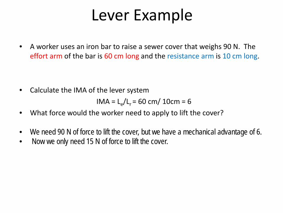
Lever Example Explanation
• A worker uses an iron bar to raise a sewer cover that weighs 90 N. The effort arm of the bar is 60 cm long and the resistance arm is 10 cm long.
• Calculate the IMA of the lever system IMA = Le/Lr = 60 cm/ 10cm = 6
• What force would the worker need to apply to lift the cover?
• We need 90 N of force to lift the cover, but we have a mechanical advantage of 6. • Now we only need 15 N of force to lift the cover.
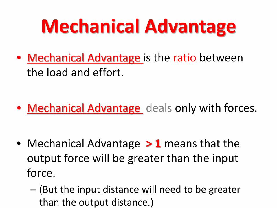
Mechanical Advantage • Mechanical Advantage is the ratio between
the load and effort.
• Mechanical Advantage deals only with forces.
• Mechanical Advantage > 1 means that the output force will be greater than the input force. – (But the input distance will need to be greater
than the output distance.)

•First and Second class levers have a positive mechanical advantage.
•Third class levers have a mechanical disadvantage, meaning you use more force that the force of the load you lift.
Mechanical Advantage

How the Lever changes the Force
“The length of the effort arm is the same number of times greater than the length of the resistance arm as the resistance to be overcome is greater than the effort you must apply.” Plugging these into an equation gives you the change in force by using a lever. where L = length of effort arm, l = length of resistance arm, R = resistance weight or force, and E= effort force.
One convenience of machines is that you can determine in advance the forces required for their operation, as well as the
forces they will exert.

“First Class Lever” • A first-class lever is a lever in
which the fulcrum is located between the input effort and the output load.
• In operation, a force is applied (by pulling or pushing) to a section of the bar, which causes the lever to swing about the fulcrum, overcoming the resistance force on the opposite side.
• The fulcrum may be at the center point of the lever as in a seesaw or at any point between the input and output.
Examples: •Seesaw
•Scissors (double lever)
Classes of Levers

Fulcrum is between EF (effort) and RF (load)
Effort moves farther than Resistance. Multiplies EF and changes its direction
First Class Lever fulcrum Effort
Resistance
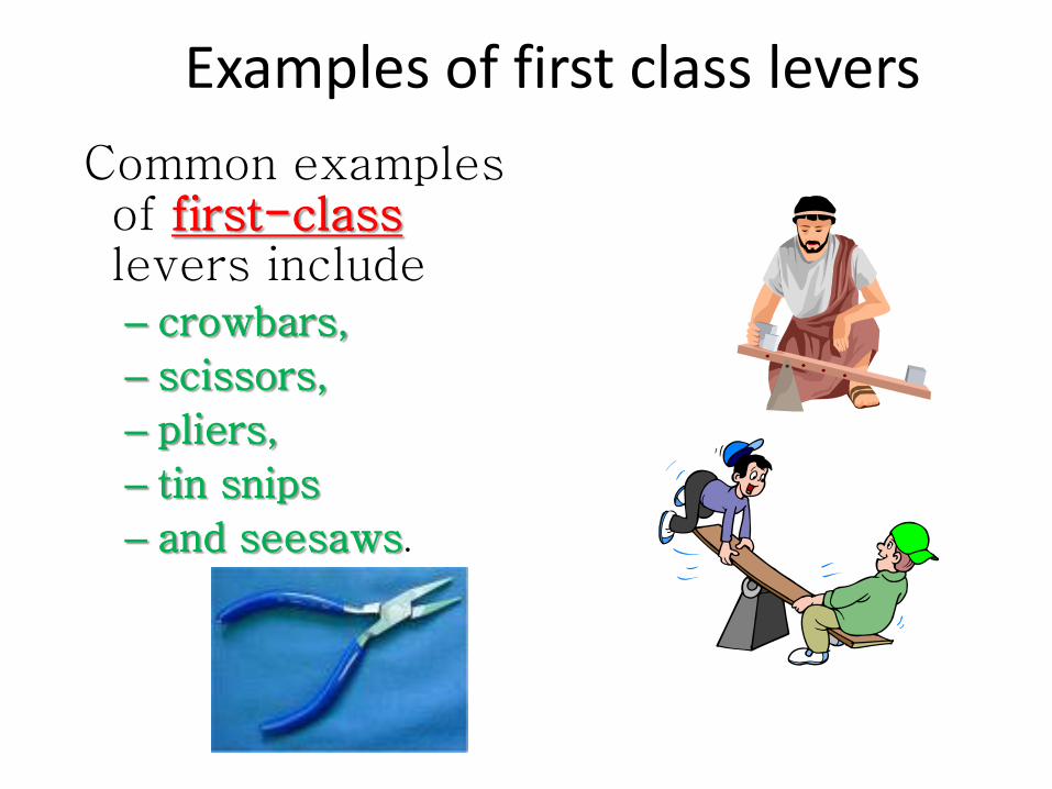
Common examples of first-class levers include – crowbars,
– scissors,
– pliers,
– tin snips
– and seesaws.
Examples of first class levers

R (load) is between fulcrum and E Effort moves further than Resistance.
Multiplies E, but does not change its direction The mechanical advantage of a lever is the ratio of the distance from the applied force to the fulcrum, to the distance from the
resistance force to the fulcrum.
Second Class Lever Effort Resistance

Explanation
• Second class lever – Resistance is located between the effort
force and the fulcrum.
– Example: Wheelbarrow
R
F
E
Always multiplies a force.

Examples:
•Paddle
•Wheelbarrow
•Wrench
Examples of Second class levers

• Examples of second-class levers include:
• nut crackers,
• wheel barrows,
• doors,
• and bottle openers.
Examples of second-class levers

EF is between fulcrum and RF (load) Does not multiply force
Resistance moves farther than Effort. Multiplies the distance the effort force travels
The mechanical advantage of a lever is the ratio of the distance from the applied force to the fulcrum to the distance of the
resistance force to the fulcrum
Third Class Lever

• For this class of levers, the input effort is higher than the output load, which is different from second-class levers and some first-class levers.
• However, the distance moved by the resistance (load) is greater than the distance moved by the effort.
• In third class levers, effort is applied between the output load on one end and the fulcrum on the opposite end.
“Third Class Lever” Examples:
•Hockey Stick
•Tweezers
•Fishing Rod

Explanation
• Third class lever – Effort force located between the resistance and the
fulcrum. – Effort arm is always shorter than resistance arm – MA is always less than one
– Example: Broom
R
F
E
There is an increase distance moved and speed at the other end. Other examples are baseball bat or hockey stick.

1st Class Lever Fulcrum is located between the effort and the resistance force
Effort and resistance forces are applied to the lever arm in the same direction
Only class of lever that can have a MA greater than or less than 1
MA =1
Effort Resistance
Resistance Effort
MA <1 Effort
Resistance
MA >1

2nd Class Lever Fulcrum is located at one end of the lever
Resistance force is located between the fulcrum and the effort force
Resistance force and effort force are in opposing directions
Always has a mechanical advantage >1 Resistance
Effort
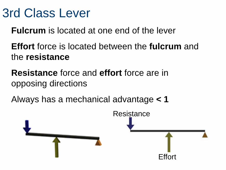
3rd Class Lever Fulcrum is located at one end of the lever
Effort force is located between the fulcrum and the resistance
Resistance force and effort force are in opposing directions
Always has a mechanical advantage < 1 Resistance
Effort

Examples of Third Class Levers
• Examples of third-class levers include:
– tweezers,
– arm hammers,
– and shovels.
Third class lever in human body.

Natural Levers Elaboration
• Identify an example of a 1st class lever in the human body
Example of first class lever in human body

Natural Levers in human body
• Identify an example of a 2nd class lever in the human body
Elaboration
Second class lever in human body

Natural Levers in human body • Identify an example of a 3rd class lever in the human body

Rotary Mechanisms • Gears, Pulleys, Cams, Ratchets, Wheels, etc.
• These rotary mechanisms transfer or change input
rotational motion and force to output motion and force.
• Output force can be either rotational or reciprocating.
Rotary mechanism rotational motion and force rotational or reciprocating motion
and force.

Belts/Pulleys & Chains/Sprockets
• Use belts and chains to convert motion and force.
• Uses the same measures of mechanical advantage for belts, pulleys, chains, sprockets and gears.
A winch consists of a small cylinder that has a crank or handle. The axle of the winch acts like the fulcrum, the handle is the effort arm. By exerting a force on the handle to turn the wheel the cable is retracting the load. Because the handle is longer than the radius of the wheel, the effort force is smaller than the load – making it act like a small lever over and over again.

Wheel & Axle A wheel is a lever arm that is fixed to a shaft, which is called an axle.
The wheel and axle move together as a simple lever to lift or to move an item by rolling.
It is important to know within the wheel and axle system which is applying the effort and resistance force – the wheel or the axle.
Can you think of an example of a wheel driving an axle?

Wheel & Axle IMA E
R
DIMA =D
DE = π [Diameter of effort (wheel or axle)]
Both effort and resistance forces will travel in a circle if unopposed.
Circumference = 2pr or πd
DR = π [Diameter resistance (wheel or axle)] ______________________ IMA = π (effort diameter) π (resistance diameter)
What is the IMA of the wheel above if the axle is driving the wheel?
What is the IMA of the wheel above if the wheel is driving the axle? 6 in. / 20 in. = .3 = .3:1 = 3:10
20 in. / 6 in. = 3.33 = 3.33:1
Ǿ6 in. Ǿ20 in.

Wheel & Axle AMA
R
E
FAMA =F
Ǿ6 in. Ǿ20 in.
200lb
70lb
What is the AMA if the wheel is driving the axle?
In this particular case we find that we need 70lb to move the load:
200lb/70lb = 2.86 = 2.86:1
What is the efficiency of the wheel and axle assembly?
= 85.9%
AMA% Efficiency = 100IMA
2.86= 1003.33
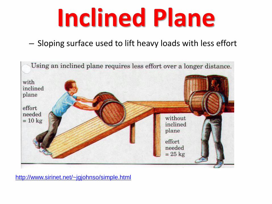
Inclined Plane – Sloping surface used to lift heavy loads with less effort
http://www.sirinet.net/~jgjohnso/simple.html
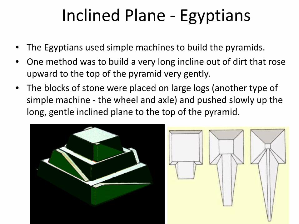
Inclined Plane - Egyptians
• The Egyptians used simple machines to build the pyramids. • One method was to build a very long incline out of dirt that rose
upward to the top of the pyramid very gently. • The blocks of stone were placed on large logs (another type of
simple machine - the wheel and axle) and pushed slowly up the long, gentle inclined plane to the top of the pyramid.

Inclined Plane - Mechanical Advantage
• The mechanical advantage of an inclined plane is equal to the length of the incline divided by the height of the incline.
• The inclined plane produces a mechanical advantage
• It does so by increasing the distance through which the force must move.

Work input and output • Work input is the amount of work done on
a machine. – Input force x input distance
• Work output is the amount of work done by a machine. – Output force x output distance
15 m
3 m
Wout = Win
Fout * Dout = Fin * Din
10N * 3m = 2N * 15m 10 N Fin
Din Dout

Screw
The mechanical advantage of an screw can be calculated by dividing the circumference by the pitch of the screw.
Pitch equals 1/ number of turns per inch.
A screw is an inclined plane wound around a central cylinder

Screw – Converts a rotary motion into a forward or
backward motion
http://www.sirinet.net/~jgjohnso/simple.html

Wedge – Converts motion in
one direction into a splitting motion that acts at right angles to the blade
– A lifting machine may use a wedge to get under a load
http://www.mos.org/sln/Leonardo/InventorsToolbox.html

Wedges
• Two inclined planes joined back to back.
• Wedges are used to split things.

Wedge – Mechanical Advantage
• The mechanical advantage of a wedge can be found by dividing the length of either slope (S) by the thickness (T) of the big end.
S • As an example, assume that the length of the slope is 10
inches and the thickness is 4 inches. • The mechanical advantage is equal to 10/4 or 2 1/2.
• As with the inclined plane, the mechanical advantage
gained by using a wedge requires a corresponding increase in distance.
T S/T
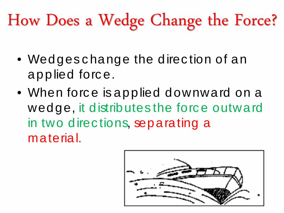
How Does a Wedge Change the Force?
• Wedges change the direction of an applied force.
• When force is applied downward on a wedge, it distributes the force outward in two directions, separating a material.
Compound Machines

A Wedge in a Compound Machine: Scissors
• The cutting edge of scissors is a wedge.
• Simple machines in a pair of scissors: – Wedge – Lever

Compound Machine: Wheelbarrow Simple Machines: -Lever -Inclined Plane -Wheel and Axel
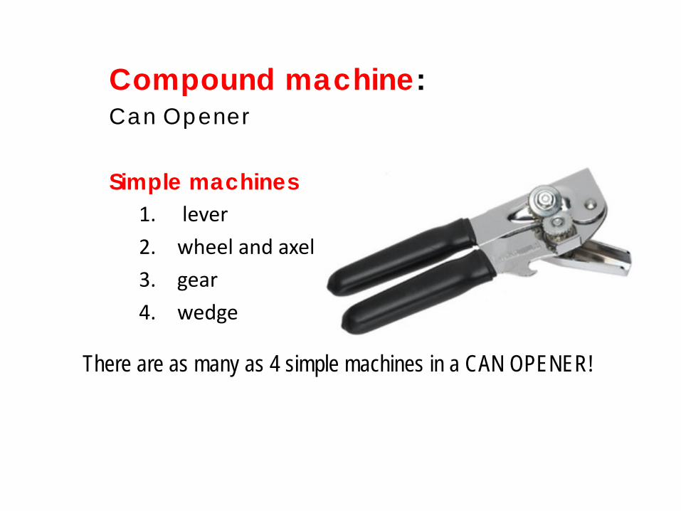
Compound machine: Can Opener Simple machines
1. lever 2. wheel and axel 3. gear 4. wedge
There are as many as 4 simple machines in a CAN OPENER!

• Ski Lift: an inclined plane to travel up a mountain.
• The pulley is used to pull the ski lift to the top of the mountain

• Crane: • The lever is the
horizontal beam that lifts the object,
• the pulley is used to make the rope tight so that it is easier for the crane to lift the object

Philosophy
• Be able to see and appreciate simple machines around you
• Be able to borrow mechanical ideas from any machine for the robot that you are building.
MACHINES - Complex Machines - Mechanical Systems
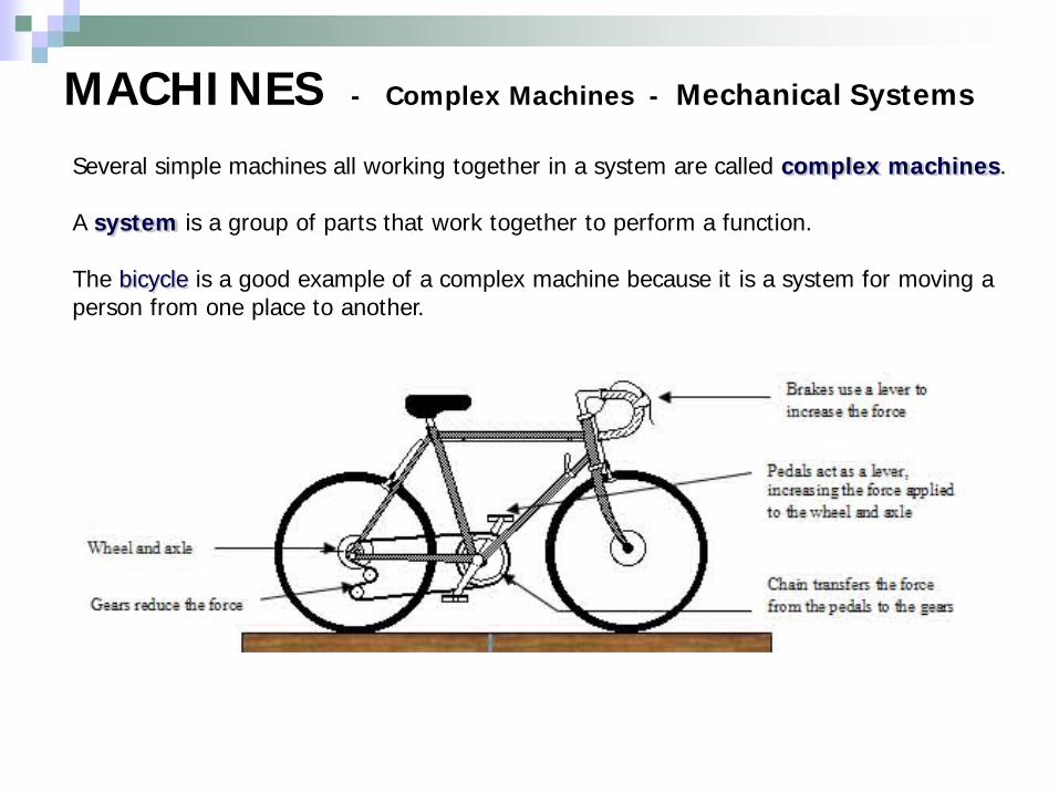
Several simple machines all working together in a system are called complex machines. A system is a group of parts that work together to perform a function. The bicycle is a good example of a complex machine because it is a system for moving a person from one place to another.
MACHINES - Complex Machines - Subsystems
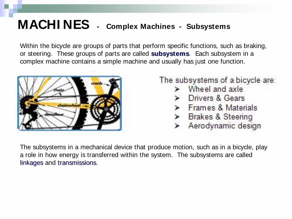
Within the bicycle are groups of parts that perform specific functions, such as braking, or steering. These groups of parts are called subsystems. Each subsystem in a complex machine contains a simple machine and usually has just one function. The subsystems in a mechanical device that produce motion, such as in a bicycle, play a role in how energy is transferred within the system. The subsystems are called linkages and transmissions.

MACHINES - Complex Machines - Subsystems
The different subsystems in a mechanical device can produce a force advantage, such as the disc brakes in a car. The brake fluid transfers the pressure from the brake pedal to the brake pads and the disc, which produces enough force to stop the car.

MACHINES - Linkage and Transmissions
The linkage is the part of the subsystem that transfers your energy from the pedals to the back wheel. In the bicycle, the chain is the linkage. In a car, the fan belt is the linkage from the engine to the cooling fan – to prevent the engine from overheating. Chains or belts form a direct link between two wheels – one that drives the motion and the other will follow in the same direction. Machines that are more complex than a bicycle move much larger loads. A special type of linkage is needed. It is called a transmission. It transfers energy from the engine to the wheels. A transmission contains a number of different gears. This enables the operator to move the object slowly with a large force, or quickly with a smaller force.

MACHINES - Gears
Gears are essential components of most mechanical systems. They consist of a pair of wheels that have teeth that interlink. When they rotate together, one gearwheel transfers turning motion and force to the other. Gears transfer energy in a mechanical system. Gear wheels – which are wheels with precisely manufactured, identical teeth around its edge - work together in gear trains of two or more wheels, transferring rotary motion and force, from one part of a complex machine to another part. Gears can be used Gears can be used to increase to change the direction of motion or decrease force or speed in a mechanical device, such as in an eggbeater.

MACHINES - Gears
A smaller gear (Y) is called a pinion. The gear that supplies the energy is called the driving gear (X). The gear to which the force is directed is called the driven gear (Y). A large gear (X) driving a smaller gear (Y) decreases torque and increases speed in the driven gear. Gears such as these are called multiplying gears. A small gear (Y) driving a larger gear (X) increases torque and reduces speed in the driven gear. Gears like these are called reducing gears. When the driving gear has fewer teeth than the driven gear, the driven gear then rotates more slowly than the driving gear. A car or bicycle in low gear uses reducing gears. When the driving and the driven gears are the same size they are known as parallel gears.