machining and machine tool unit 1&2
TRANSCRIPT

11
Machining and Machine toolsPresented By,
Alakshendra Pratap Singh
Asst. Prof.,
Mechanical Engineering Department,
Jodhpur Institute of Engineering and Technology,
jodhpur, Rajasthan

2
Metal Cutting
33
Introduction
• Object of mfg process is to produce piece of specified shape and material properties.
• Any of the following three type of operations may be employed for the same:
1. Constant Mass Operation (Casting, rolling etc.)
2. Material Addition Operation (Welding, Bolting, riveting etc)
3. Material Removal Operation (Machining, grinding, lapping etc)

44
Types of Material Removal Operations:
Conventional:
•Milling•Turning•Shaping• Grinding
Unconventional:
• Electro Chemical Machining• Electro Discharge Machining
Abrasive processes:
• Grinding• Deburring
Metal cutting is commonly used because:• Casting and forging cannot give precisions shapes• Its often easier to machine parts to get complicated shapes.
55
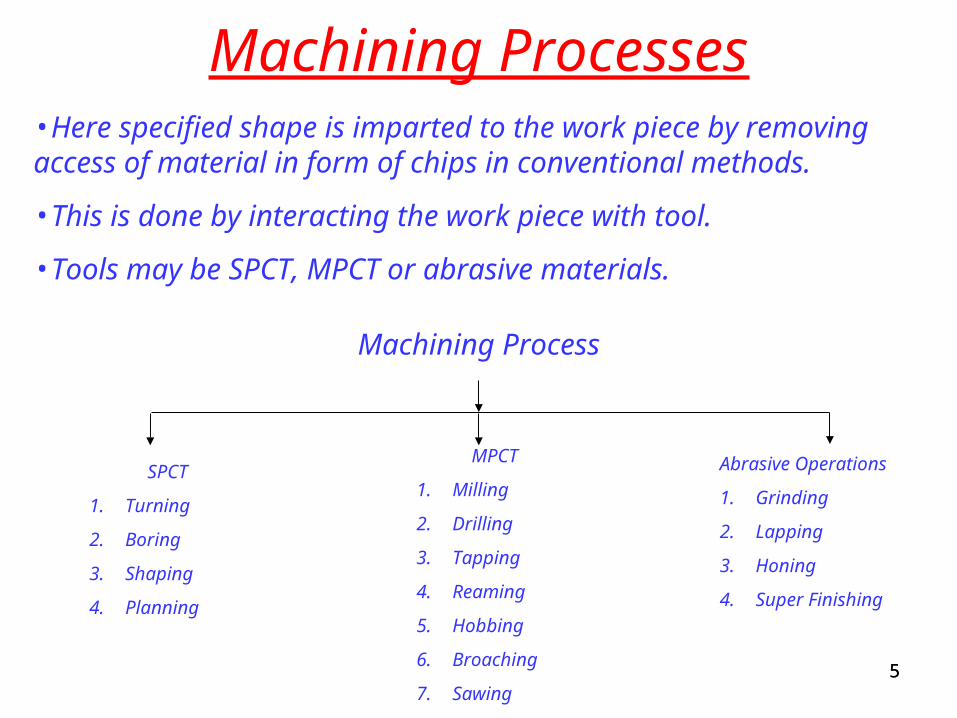
Machining Processes•Here specified shape is imparted to the work piece by removing access of material in form of chips in conventional methods.
•This is done by interacting the work piece with tool.
•Tools may be SPCT, MPCT or abrasive materials.
Machining Process
SPCT
1. Turning
2. Boring
3. Shaping
4. Planning
MPCT
1. Milling
2. Drilling
3. Tapping
4. Reaming
5. Hobbing
6. Broaching
7. Sawing
Abrasive Operations
1. Grinding
2. Lapping
3. Honing
4. Super Finishing
66
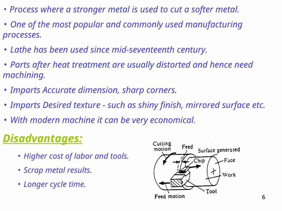
• Process where a stronger metal is used to cut a softer metal.
• One of the most popular and commonly used manufacturing processes.
• Lathe has been used since mid-seventeenth century.
• Parts after heat treatment are usually distorted and hence need machining.
• Imparts Accurate dimension, sharp corners.
• Imparts Desired texture - such as shiny finish, mirrored surface etc.
• With modern machine it can be very economical.
Disadvantages:
• Higher cost of labor and tools.
• Scrap metal results.
• Longer cycle time.

77
Oblique vs orthogonal cuttingOblique Cutting:• Cutting Edge of tool is inclined at an angle λs with normal to cutting velocity vector.
• Chip generated flows on rake face of the tool at angle approx equal to angle of inclination (λs) to the normal.
• Cutting edge extends beyond the work piece width on both sides.
• Cutting forces act along all the three directions in x, y and z axes.
• Suitable for efficient metal removal.
V

88
Orthogonal Cutting Oblique Cutting
VV

99
Orthogonal Cutting:• Cutting edge is perpendicular to direction of cutting velocity (V).
• λs = 0
• Cutting edge extends beyond the work piece width on both sides.
• Chip generated flows on rake face of the tool with chip velocity perpendicular to cutting edge.
• Cutting forces act along x and z directions only.
• Unsuitable for efficient chip removal.

1010
Mechanics of chip formation: • Wedge shape tool is moved relative to work piece.
• Tool exerts pressure on work piece as it makes contact with the same causing compression of metal near tool tip.
• Shear type plastic deformation within metal starts.
• Metal starts moving upwards along the top face of the tool.
• Tool advances and material ahead is sheared continuously along shear plane (Primary shear zone).
• Tool surface along which chip moves upwards is called rake surface.
• Tool surface which is helps in avoiding rubbing with machined surface is called rake surface.
1111
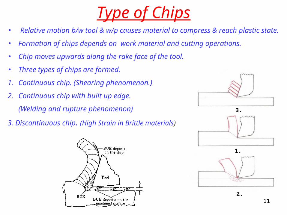
Type of Chips• Relative motion b/w tool & w/p causes material to compress & reach
plastic state.
• Formation of chips depends on work material and cutting operations.
• Chip moves upwards along the rake face of the tool.
• Three types of chips are formed.
1. Continuous chip. (Shearing phenomenon.)
2. Continuous chip with built up edge.
(Welding and rupture phenomenon)
3. Discontinuous chip. (High Strain in Brittle materials)
1.
2.
3.

1212
Factors Type of chipContinuous Continuous with BUE
Discontinuous
Material Ductile DuctileBrittle
Tool:
Rake Angle Large Small Small
Cutting Edge Sharp Dull ----
Cutting Condition:
Speed High Low Low
Feed Low High High
Friction Low High ---
Cutting Fluid Efficient Poor Effective
Chip Thickness Small Large
Surface Finish: ---- Poor Better

1313
Single Point Cutting Tool:• A single-point tool is a cutting tool having one cutting part and one shank.
Tool Elements:
Shank: That part of the tool by which it is held.
Tool Axis: An imaginary straight line used for manufacturing and sharpening of the tool and for holding the tool in use. Generally, the tool axis is the center line of the tool shank.
Cutting Part or tool point: The functional part of the tool comprised of the chip producing elements. The cutting edges, face, and flank are therefore elements of the cutting part.
Base. A flat surface on the tool shank, parallel or perpendicular to the tool reference plane useful for locating or orienting the tool in its manufacture, sharpening and measurement. Not all tools have a clearly defined base.
Wedge. The portion of the cutting part enclosed between the face and the flank. It can be associated with either the major or minor cutting edge.

1414
Tool Surfaces:
•Rake Face (Ay): The surface or surfaces over which the chip flows.
•Chip Breaker: A modification of the face, to control or break the chip.
•Cutting Edge: That edge of the face which is intended to perform cutting.
Major/Side Cutting Edge: Edge which is intended to produce transient surface.
Minor/End Cutting Edge: Edge which is not intended to produce transient surface.
•Flank (Aa): The tool surface or surfaces over which the surface produced on the work piece passes.
Major /Principal/Side Flank Surface: Flank Surface containing major cutting edge.
Minor/Auxiliary/End Flank Surface: Flank Surface Containing minor cutting edge.
•Corner or nose: The relatively small portion of the cutting edge at the junction of the major and minor cutting edges

1515
1616
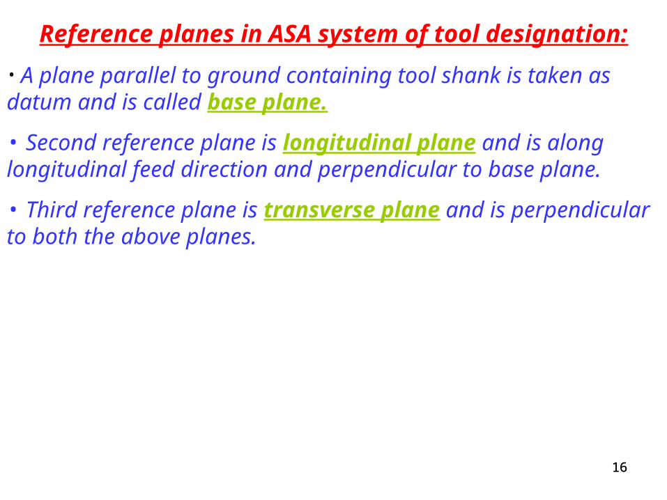
Reference planes in ASA system of tool designation:
• A plane parallel to ground containing tool shank is taken as datum and is called base plane.
• Second reference plane is longitudinal plane and is along longitudinal feed direction and perpendicular to base plane.
• Third reference plane is transverse plane and is perpendicular to both the above planes.
1717

1818American System of Tool Specification

1919
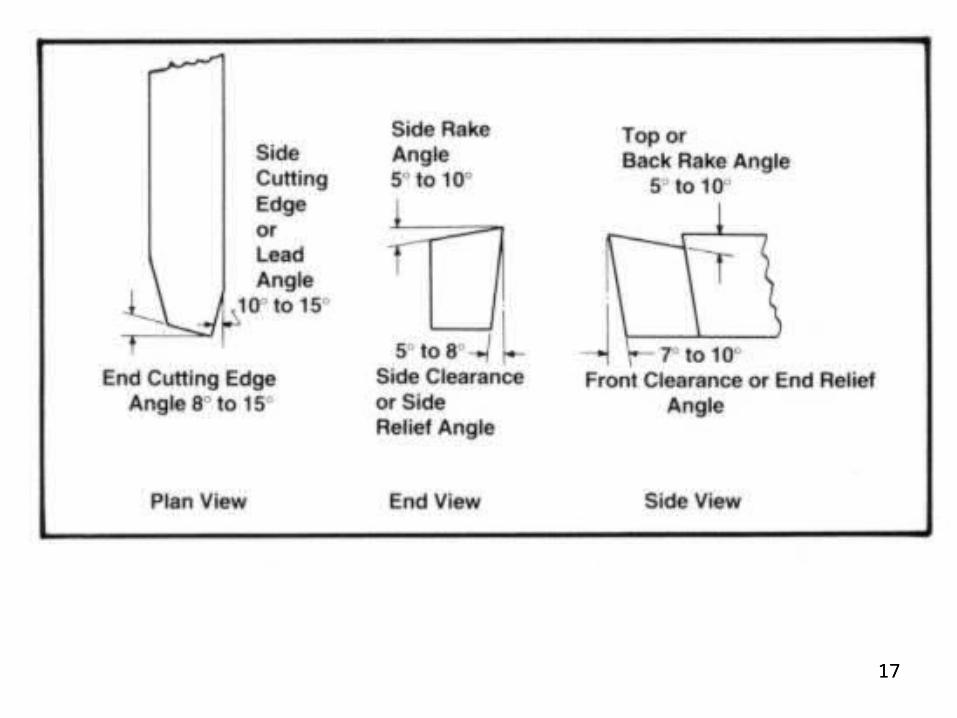
American System of Tool Specification
αb αs βe βs γe γs rBack Rake Angle
Side Rake Angle
End Relief/Flank/clearance Angle
Side Relief/Flank/clearance Angle
End Cutting Angle
Side Cutting Angle
Nose Radius

2020
Importance and selection of angles
Back Rake Angle (αb):
• It is the angle b/w rake face of the tool and line parallel to the base.• Measured in a plane perpendicular to major (side) cutting edge.• It is positive when major (side) cutting edge slopes downwards from the point towards the shank and vice versa.
Side Rake Angle (αs):
• It is the angle b/w face of the tool and line parallel to the base.• Measured in a plane perpendicular to the base and major (side) cutting edge.• It gives slope of the face of the tool from cutting edge.• It is positive when slope is away from cutting edge and vice versa.
Importance:• Larger the rake angle, smaller is the cutting angle and low cutting force and power will be required.• Decreasing cutting angle will leave less metal at point of tool to support cutting edge and conduct away the heat reducing the tool strength.

2121
End Relief/Flank/clearance Angle (βe):
• Angle b/w portion of end (minor) flank immediately below minor (end) cutting edge and a line perpendicular to the base of the tool.• Measured at right angle to minor flank surface.
Side Relief/Flank/clearance Angle (βs):
• Angle b/w portion of side flank immediately below major (side) cutting edge and a line perpendicular to the base of the tool.• Measured at right angle to Major (side) flank.
Importance:
• Provided to avoid the rubbing of work piece and the tool during cutting.• Flank of the tool clears the work piece surface and there is no rubbing action b/w the two.• Higher the relief angle, better will be the penetration and cut made by the tool on work piece thus less cutting force and power required and lower will be the flank face wear.• But large rake angles weaken the cutting edge and heat dissipation is also poor.

2222
End Cutting Angle (γe):
• Angle b/w minor (end) cutting edge and line normal to tool shank.
Importance:
• Provides clearance or relief to trailing end of the cutting edge to prevent rubbing b/w machined surface and trailing (non cutting) part of the tool.
Side Cutting Angle or Lead Angle (γs):
• Angle b/w major (side) cutting edge and side of the tool shank.
Importance:
• Provides interface as the tool enters the work material.• This angle affects tool life and surface finish.
Nose Radius (r):
• For long tool life and surface finish.

2323
Left and Right hand Cutting Tool:
•In a right cut tool side (major or primary) cutting edge is on the side of the thumb when right hand is placed on the tool with palm downward and fingers pointing towards the tool nose.
•Such tool cuts when fed from right to left.
•In a left cut tool side (major or primary) cutting edge is on the thumb side when left hand is placed on the tool with palm downward and fingers pointing towards the tool nose.
• Such tool cuts when fed from left to right.

2424
Measurement of Shear Angle (Φ)• Shear Angle Φis defined as the angle made by shear plane with direction of tool travel.
• Cutting Ratio or Chip thickness ratio or chip compression factor:
• Cutting ratio (r) is defined as the uncut chip thickness (t0) to chip thickness after metal is cut (tc).
r = t0/tc
• Chip reduction factor (ζ) is the reciprocal of Cutting ratio.
ζ = 1/r = tc/t0
A
B

2525

2626
tanΦ = r*cosα/(1-r*sin α)
Now,
AB = to/sinΦ = tc/cos(Φ-α)
i.e. r = sinΦ / (cosΦcosα + sinΦsinα)
r*(cosΦcosα + sinΦsinα) = sinΦ
tanΦ = r*cosα/(1-r*sin α)
• This is a relationship between rake angle and shear angle.

2727
•Now if the length of cut ‘lo’ is known, then as per continuity equation:
ρlobt = ρlcbtc
Where,
• ρ is the density of the material and material is assumed to be incompressible.
• lc is the length of the chip.
lc/lo = to/tc = r
• Thus relation b/w rake angle and shear angle can be redefined.

2828
Cutting forces:Forces in cutting are to be calculated to:• Ensure that the machine used can withstand such forces.•To help minimize wear on tools and reduce power consumption.
Forces across shear plane:Fs: Shear ForceFn: Force normal to shear planeα: positive tool rake angle.Φ: Shear angleλ: Friction angle.
Force at chip tool interface:F: Friction ForceN: Normal Tool Force
Other Forces:Fc: Cutting ForceFt: Thrust ForceR: Resultant Forceμ: F/N = tan λ
Force Triangles

2929
• Shear Force ‘Fs’ is resistance to shear of metal.• Normal Force ‘Fn’ is the force that w/p provides for backing up.• Fs and Fn are at right angle to each other.• R’ is the resultant of Fs and Fn and equal and opposite to R which is the resultant of F and N. Thus R’ and R can be used interchangeably. • Normal Tool Force ‘N’ acts at tool chip interface and is provided by the tool.• Frictional Force ‘F’ is the frictional resistance of the tool acting on chip.• All these forces can be represented with a circle called Merchant Force Circle.• On this circle force triangles are superimposed.• R or R’ forms the diameter of this circle.
Merchant Force Circle
• Orthogonal components of R, cutting force Fc (horizontal) and thrust force Ft (vertical) can be measure with the help of dynamometer.• Power consumed during cutting ‘E’ is:
E = Fc*V• Where V is cutting speed.• Now:
VV
F = Fc*Sinα + Ft*CosαN = Fc*Cosα – Ft*Sinα
AndFs = Fc*CosΦ – Ft*SinΦFn = Fc*SinΦ – Ft*CosΦ
V

3030
Now,
Shear Plane Area ‘As’ isAs = bto/sinΦ
And average stresses on shear plane area are:
Τs = Fs/Asσs = Fn/As
Also from Merchant Force Circle:
Also;\R = Fc*sec(λ-α)
Thus, Fs = Fc*sec(λ-α)*Cos(Φ+λ-α)Since, Τs = Fs*SinΦ/btoThus, Τs = Fc*sec(λ-α)*Cos(Φ+λ-α)*SinΦ/btoNow ‘α’ for a tool is constant and assuming that ‘λ’ is independent of ‘Φ’, and for Maximum shear stress:
dΤs/dΦ = 0
Cos(Φ+λ-α)*CosΦ - Sin(Φ+λ-α)*SinΦ
Fs = R*Cos(Φ+λ-α) and
Fc = R*Cos(λ-α)
31
Now,
Cutting Power Pc:
Pc = Fc*V
V = ΠDN/(1000*60) in m/s
Thus,
Pc = Fc*V/1000 in Kw
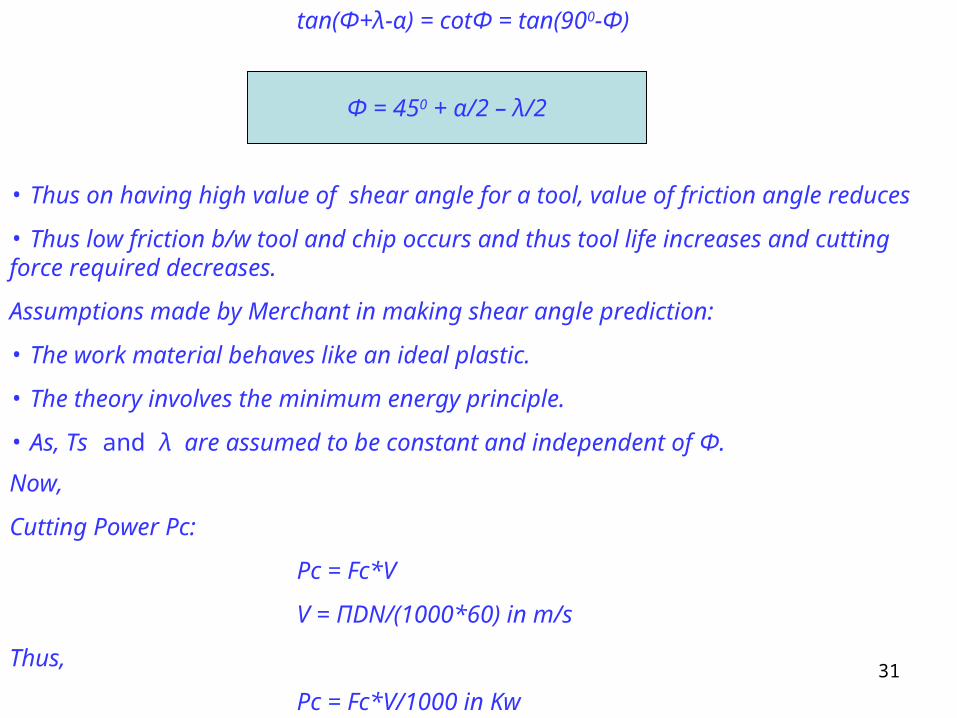
tan(Φ+λ-α) = cotΦ = tan(900-Φ)
• Thus on having high value of shear angle for a tool, value of friction angle reduces
• Thus low friction b/w tool and chip occurs and thus tool life increases and cutting force required decreases.
Assumptions made by Merchant in making shear angle prediction:
• The work material behaves like an ideal plastic.
• The theory involves the minimum energy principle.
• As, Τs and λ are assumed to be constant and independent of Φ.
Φ = 450 + α/2 – λ/2