machining, forming and forging tests - phoenix tribology · machining, forming and forging tests...
TRANSCRIPT
Machining, Forming and Forging Tests
Introduction ............................................................................................. 3
Lubricant Screening .................................................................................. 5
Continuous Sliding Tests ......................................................................... 6
Pin on Vee Block ................................................................................. 6
Four Ball Test ..................................................................................... 6
Block on Ring Test ............................................................................... 7
Reciprocating Tests ................................................................................ 7
Basic Friction Tests ................................................................................... 8
Ring Compression Test ........................................................................... 8
Plane Strain Compression Test................................................................. 9
Twist Compression Test .......................................................................... 9
Pin on Disc .......................................................................................... 10
Friction Test at High Temperatures ........................................................... 10
DC Heated Pin on Disc Rig (National Physical Laboratory) ......................... 11
High Load Friction Rig (National Physical Laboratory) ............................... 11
Tool Wear Tests ...................................................................................... 12
Cutting Tests .......................................................................................... 12
Falex Tapping Torque Test .................................................................... 12
Single Chip Test ................................................................................... 13
Machine Tool Tests ............................................................................... 13
Forming Tests ........................................................................................ 14
Hemispherical/Erichsen and Olsen Dome Tests ........................................ 14
Strip Draw Test ................................................................................... 15
Roller Bead Test .................................................................................. 15

Load Scanner ...................................................................................... 17
Forging Tests ......................................................................................... 19
Rolling Tests .......................................................................................... 19
Laboratory Scale Mill ............................................................................ 20
In-situ Friction Measurement ................................................................. 20
Two Roller Machine .............................................................................. 21
Conclusion ............................................................................................. 22
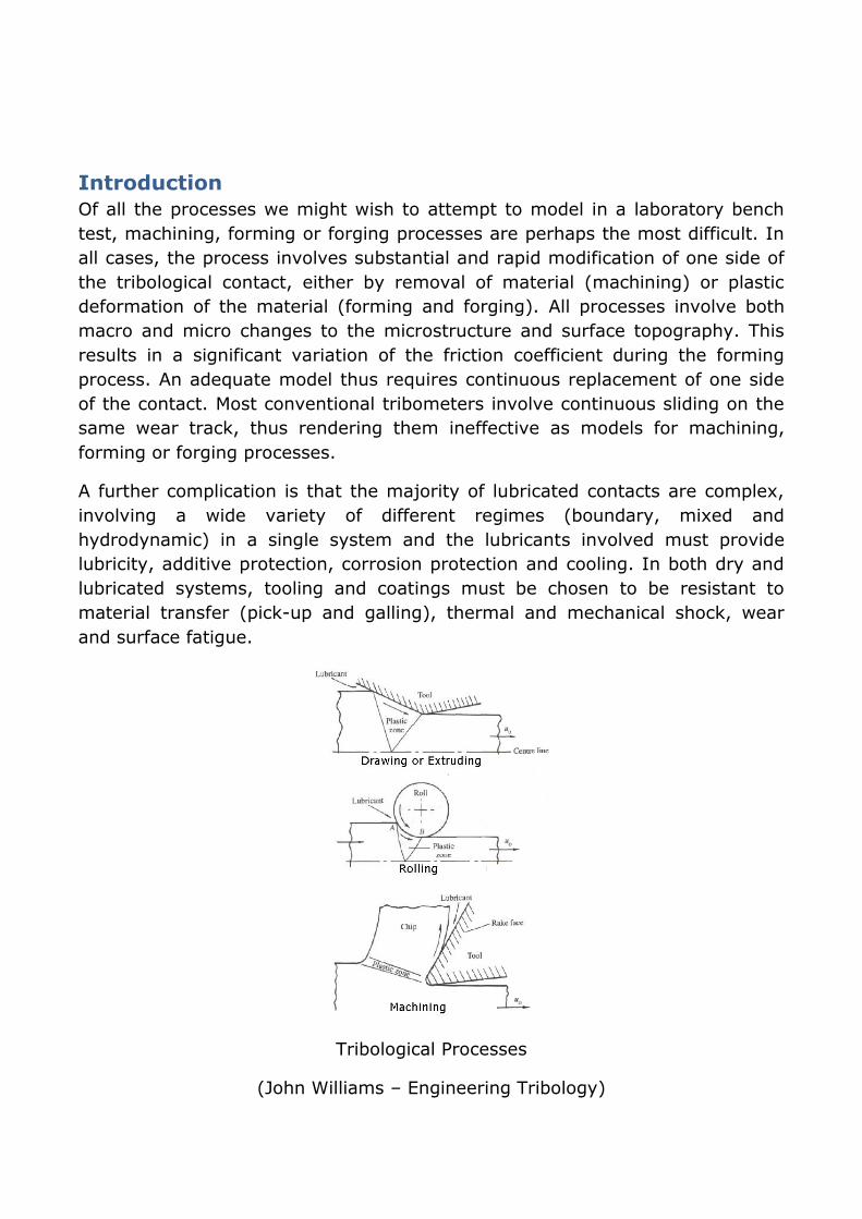
Introduction
Of all the processes we might wish to attempt to model in a laboratory bench
test, machining, forming or forging processes are perhaps the most difficult. In
all cases, the process involves substantial and rapid modification of one side of
the tribological contact, either by removal of material (machining) or plastic
deformation of the material (forming and forging). All processes involve both
macro and micro changes to the microstructure and surface topography. This
results in a significant variation of the friction coefficient during the forming
process. An adequate model thus requires continuous replacement of one side
of the contact. Most conventional tribometers involve continuous sliding on the
same wear track, thus rendering them ineffective as models for machining,
forming or forging processes.
A further complication is that the majority of lubricated contacts are complex,
involving a wide variety of different regimes (boundary, mixed and
hydrodynamic) in a single system and the lubricants involved must provide
lubricity, additive protection, corrosion protection and cooling. In both dry and
lubricated systems, tooling and coatings must be chosen to be resistant to
material transfer (pick-up and galling), thermal and mechanical shock, wear
and surface fatigue.
Tribological Processes
(John Williams – Engineering Tribology)
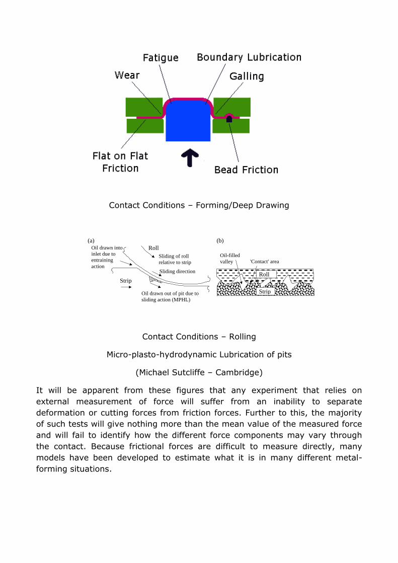
Contact Conditions – Forming/Deep Drawing
Sliding of roll
relative to strip
Strip
Roll Oil drawn into
inlet due to
entraining
action
Oil drawn out of pit due to
sliding action (MPHL)
Sliding direction
(a) (b)
Strip
Roll
'Contact' area
Oil-filled
valley
Contact Conditions – Rolling
Micro-plasto-hydrodynamic Lubrication of pits
(Michael Sutcliffe – Cambridge)
It will be apparent from these figures that any experiment that relies on
external measurement of force will suffer from an inability to separate
deformation or cutting forces from friction forces. Further to this, the majority
of such tests will give nothing more than the mean value of the measured force
and will fail to identify how the different force components may vary through
the contact. Because frictional forces are difficult to measure directly, many
models have been developed to estimate what it is in many different metal-
forming situations.
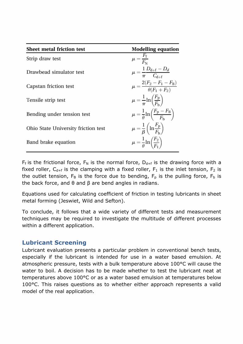
Ff is the frictional force, FN is the normal force, Dd+f is the drawing force with a
fixed roller, Cd+f is the clamping with a fixed roller, F1 is the inlet tension, F2 is
the outlet tension, FB is the force due to bending, Fp is the pulling force, Fb is
the back force, and θ and β are bend angles in radians.
Equations used for calculating coefficient of friction in testing lubricants in sheet
metal forming (Jeswiet, Wild and Sefton).
To conclude, it follows that a wide variety of different tests and measurement
techniques may be required to investigate the multitude of different processes
within a different application.
Lubricant Screening
Lubricant evaluation presents a particular problem in conventional bench tests,
especially if the lubricant is intended for use in a water based emulsion. At
atmospheric pressure, tests with a bulk temperature above 100°C will cause the
water to boil. A decision has to be made whether to test the lubricant neat at
temperatures above 100°C or as a water based emulsion at temperatures below
100°C. This raises questions as to whether either approach represents a valid
model of the real application.
Continuous Sliding Tests
For many years, a number of basic continuous sliding lubricant screening tests
have been in existence and extensively used, each claiming to provide useful
data but in reality of limited scope. The machines are all thermally self-
regulating continuous energy pulse devices, in which contact temperature is
both uncontrolled and cannot be measured.
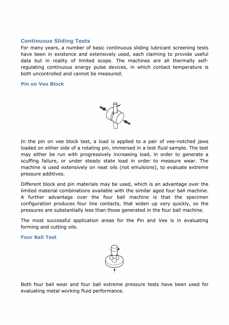
Pin on Vee Block
In the pin on vee block test, a load is applied to a pair of vee-notched jaws
loaded on either side of a rotating pin, immersed in a test fluid sample. The test
may either be run with progressively increasing load, in order to generate a
scuffing failure, or under steady state load in order to measure wear. The
machine is used extensively on neat oils (not emulsions), to evaluate extreme
pressure additives.
Different block and pin materials may be used, which is an advantage over the
limited material combinations available with the similar aged four ball machine.
A further advantage over the four ball machine is that the specimen
configuration produces four line contacts, that widen up very quickly, so the
pressures are substantially less than those generated in the four ball machine.
The most successful application areas for the Pin and Vee is in evaluating
forming and cutting oils.
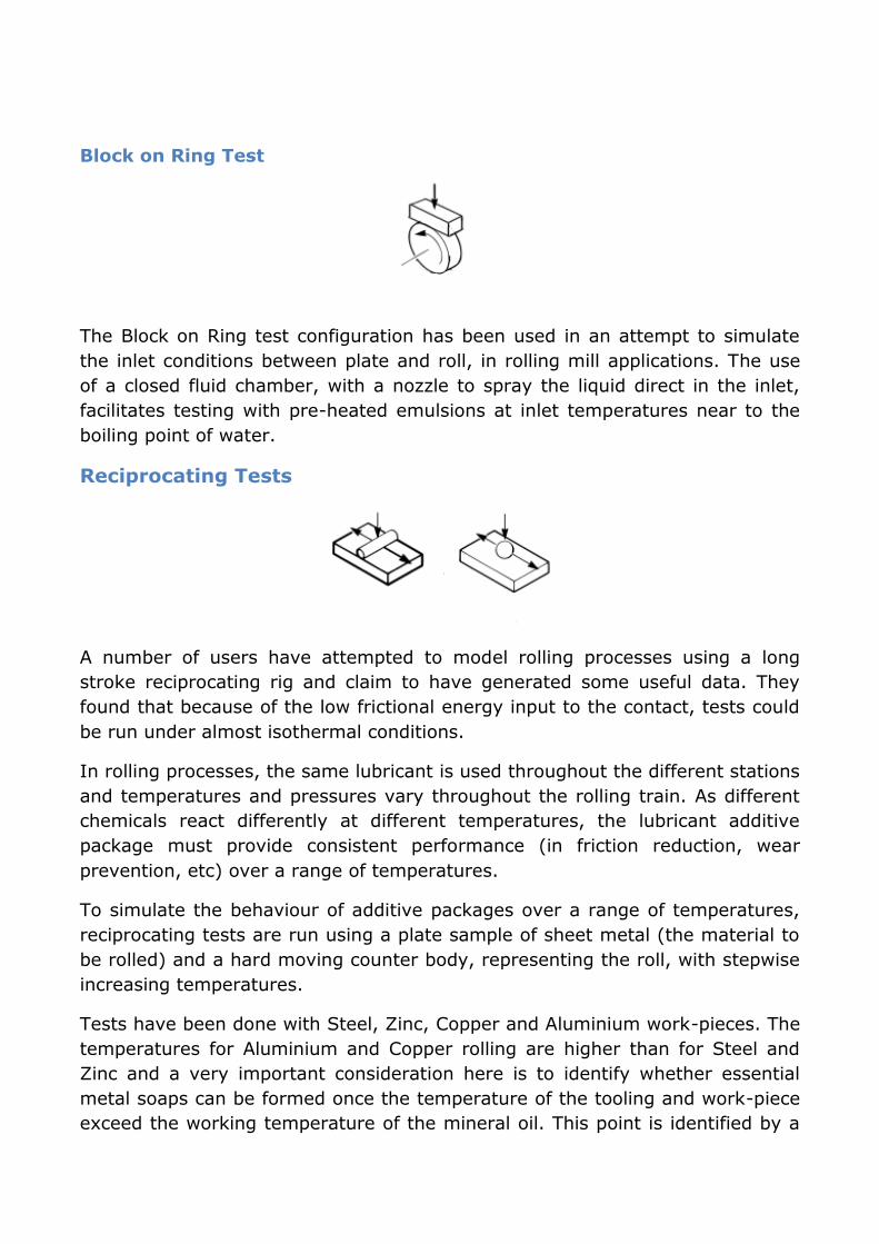
Four Ball Test
Both four ball wear and four ball extreme pressure tests have been used for
evaluating metal working fluid performance.
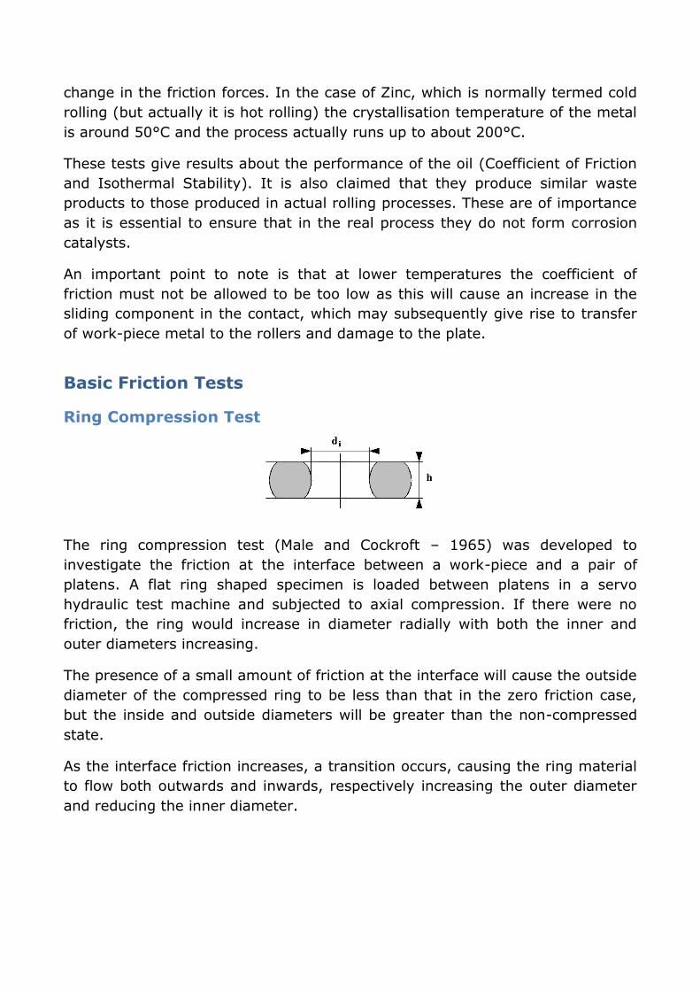
Block on Ring Test
The Block on Ring test configuration has been used in an attempt to simulate
the inlet conditions between plate and roll, in rolling mill applications. The use
of a closed fluid chamber, with a nozzle to spray the liquid direct in the inlet,
facilitates testing with pre-heated emulsions at inlet temperatures near to the
boiling point of water.
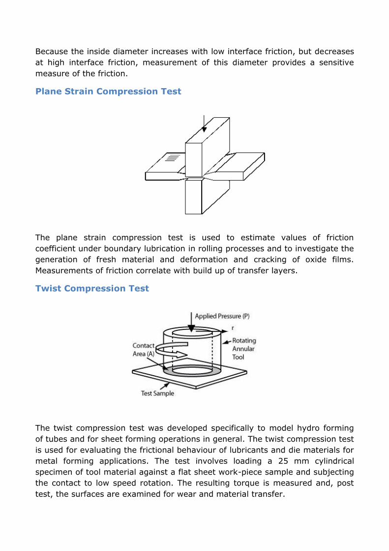
Reciprocating Tests
A number of users have attempted to model rolling processes using a long
stroke reciprocating rig and claim to have generated some useful data. They
found that because of the low frictional energy input to the contact, tests could
be run under almost isothermal conditions.
In rolling processes, the same lubricant is used throughout the different stations
and temperatures and pressures vary throughout the rolling train. As different
chemicals react differently at different temperatures, the lubricant additive
package must provide consistent performance (in friction reduction, wear
prevention, etc) over a range of temperatures.
To simulate the behaviour of additive packages over a range of temperatures,
reciprocating tests are run using a plate sample of sheet metal (the material to
be rolled) and a hard moving counter body, representing the roll, with stepwise
increasing temperatures.
Tests have been done with Steel, Zinc, Copper and Aluminium work-pieces. The
temperatures for Aluminium and Copper rolling are higher than for Steel and
Zinc and a very important consideration here is to identify whether essential
metal soaps can be formed once the temperature of the tooling and work-piece
exceed the working temperature of the mineral oil. This point is identified by a
change in the friction forces. In the case of Zinc, which is normally termed cold
rolling (but actually it is hot rolling) the crystallisation temperature of the metal
is around 50°C and the process actually runs up to about 200°C.
These tests give results about the performance of the oil (Coefficient of Friction
and Isothermal Stability). It is also claimed that they produce similar waste
products to those produced in actual rolling processes. These are of importance
as it is essential to ensure that in the real process they do not form corrosion
catalysts.
An important point to note is that at lower temperatures the coefficient of
friction must not be allowed to be too low as this will cause an increase in the
sliding component in the contact, which may subsequently give rise to transfer
of work-piece metal to the rollers and damage to the plate.
Basic Friction Tests
Ring Compression Test
The ring compression test (Male and Cockroft – 1965) was developed to
investigate the friction at the interface between a work-piece and a pair of
platens. A flat ring shaped specimen is loaded between platens in a servo
hydraulic test machine and subjected to axial compression. If there were no
friction, the ring would increase in diameter radially with both the inner and
outer diameters increasing.
The presence of a small amount of friction at the interface will cause the outside
diameter of the compressed ring to be less than that in the zero friction case,
but the inside and outside diameters will be greater than the non-compressed
state.
As the interface friction increases, a transition occurs, causing the ring material
to flow both outwards and inwards, respectively increasing the outer diameter
and reducing the inner diameter.
Because the inside diameter increases with low interface friction, but decreases
at high interface friction, measurement of this diameter provides a sensitive
measure of the friction.
Plane Strain Compression Test
The plane strain compression test is used to estimate values of friction
coefficient under boundary lubrication in rolling processes and to investigate the
generation of fresh material and deformation and cracking of oxide films.
Measurements of friction correlate with build up of transfer layers.
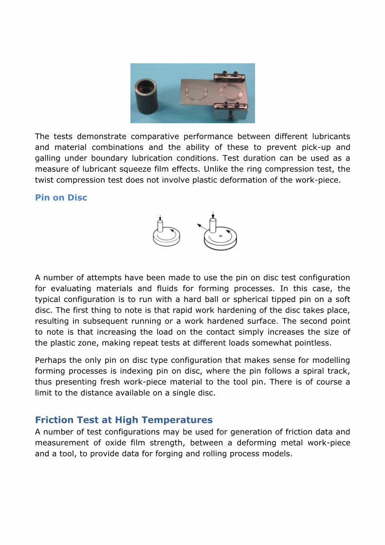
Twist Compression Test
The twist compression test was developed specifically to model hydro forming
of tubes and for sheet forming operations in general. The twist compression test
is used for evaluating the frictional behaviour of lubricants and die materials for
metal forming applications. The test involves loading a 25 mm cylindrical
specimen of tool material against a flat sheet work-piece sample and subjecting
the contact to low speed rotation. The resulting torque is measured and, post
test, the surfaces are examined for wear and material transfer.
The tests demonstrate comparative performance between different lubricants
and material combinations and the ability of these to prevent pick-up and
galling under boundary lubrication conditions. Test duration can be used as a
measure of lubricant squeeze film effects. Unlike the ring compression test, the
twist compression test does not involve plastic deformation of the work-piece.
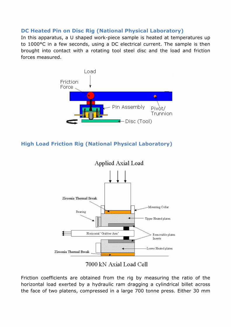
Pin on Disc
A number of attempts have been made to use the pin on disc test configuration
for evaluating materials and fluids for forming processes. In this case, the
typical configuration is to run with a hard ball or spherical tipped pin on a soft
disc. The first thing to note is that rapid work hardening of the disc takes place,
resulting in subsequent running or a work hardened surface. The second point
to note is that increasing the load on the contact simply increases the size of
the plastic zone, making repeat tests at different loads somewhat pointless.
Perhaps the only pin on disc type configuration that makes sense for modelling
forming processes is indexing pin on disc, where the pin follows a spiral track,
thus presenting fresh work-piece material to the tool pin. There is of course a
limit to the distance available on a single disc.
Friction Test at High Temperatures
A number of test configurations may be used for generation of friction data and
measurement of oxide film strength, between a deforming metal work-piece
and a tool, to provide data for forging and rolling process models.
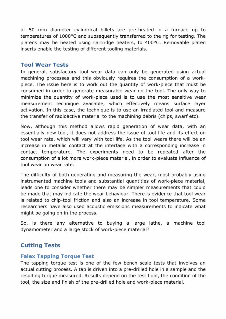
DC Heated Pin on Disc Rig (National Physical Laboratory)
In this apparatus, a U shaped work-piece sample is heated at temperatures up
to 1000°C in a few seconds, using a DC electrical current. The sample is then
brought into contact with a rotating tool steel disc and the load and friction
forces measured.
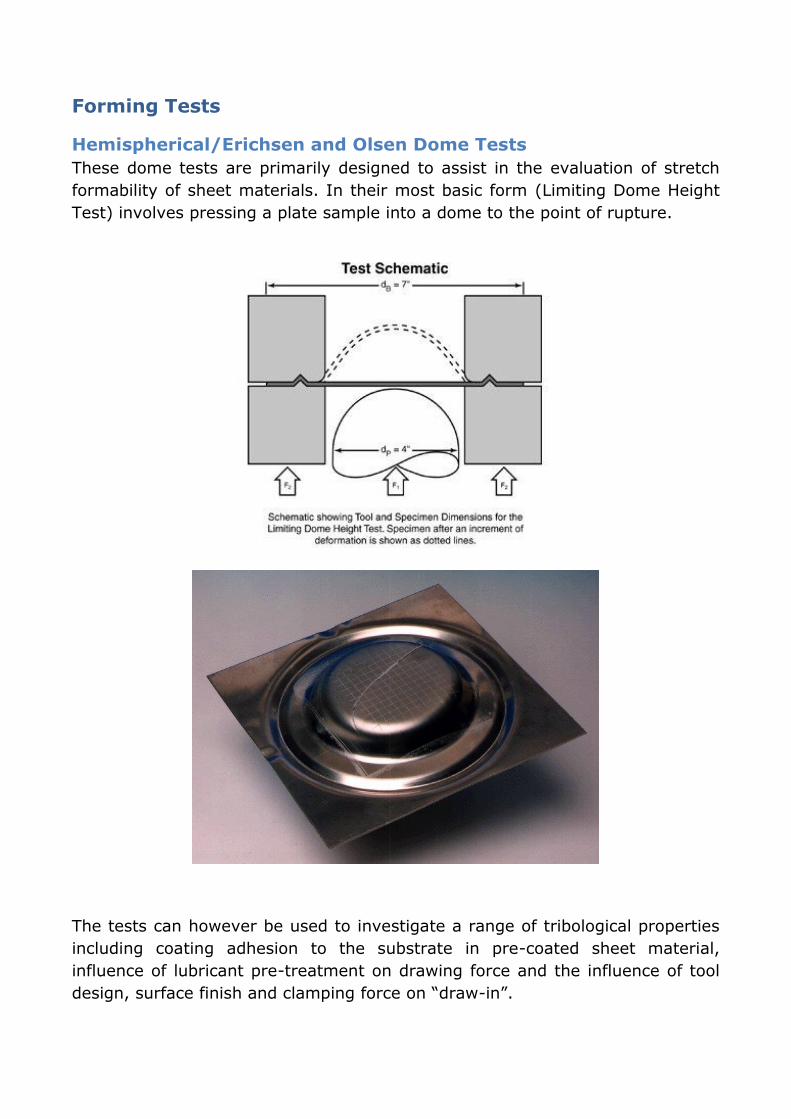
High Load Friction Rig (National Physical Laboratory)
Friction coefficients are obtained from the rig by measuring the ratio of the
horizontal load exerted by a hydraulic ram dragging a cylindrical billet across
the face of two platens, compressed in a large 700 tonne press. Either 30 mm
or 50 mm diameter cylindrical billets are pre-heated in a furnace up to
temperatures of 1000°C and subsequently transferred to the rig for testing. The
platens may be heated using cartridge heaters, to 400°C. Removable platen
inserts enable the testing of different tooling materials.
Tool Wear Tests
In general, satisfactory tool wear data can only be generated using actual
machining processes and this obviously requires the consumption of a work-
piece. The issue here is to work out the quantity of work-piece that must be
consumed in order to generate measurable wear on the tool. The only way to
minimize the quantity of work-piece used is to use the most sensitive wear
measurement technique available, which effectively means surface layer
activation. In this case, the technique is to use an irradiated tool and measure
the transfer of radioactive material to the machining debris (chips, swarf etc).
Now, although this method allows rapid generation of wear data, with an
essentially new tool, it does not address the issue of tool life and its effect on
tool wear rate, which will vary with tool life. As the tool wears there will be an
increase in metallic contact at the interface with a corresponding increase in
contact temperature. The experiments need to be repeated after the
consumption of a lot more work-piece material, in order to evaluate influence of
tool wear on wear rate.
The difficulty of both generating and measuring the wear, most probably using
instrumented machine tools and substantial quantities of work-piece material,
leads one to consider whether there may be simpler measurements that could
be made that may indicate the wear behaviour. There is evidence that tool wear
is related to chip-tool friction and also an increase in tool temperature. Some
researchers have also used acoustic emissions measurements to indicate what
might be going on in the process.
So, is there any alternative to buying a large lathe, a machine tool
dynamometer and a large stock of work-piece material?
Cutting Tests
Falex Tapping Torque Test
The tapping torque test is one of the few bench scale tests that involves an
actual cutting process. A tap is driven into a pre-drilled hole in a sample and the
resulting torque measured. Results depend on the test fluid, the condition of the
tool, the size and finish of the pre-drilled hole and work-piece material.

Substantial work had to be done under ASTM to arrive a test that has a good
repeatability. Specimens must be extremely repeatable; taps must be
'qualified', which means that only taps that fall within a certain error when
testing them in a reference fluid, may be selected. Only then are differences in
performance, which may be as small as 1 or 2 %, measurable. It makes the
test tedious and expensive but is to date the only ASTM laboratory method for
cutting performance.
Single Chip Test
A number of experimenters have performed tests to investigate the forces and
energy involved in the formation of a single chip. One approach was to use the
equivalent of a small Charpy tester, but with a machine tool tip secured to the
bottom end of the pendulum. A plate sample was carried in a heated bath,
mounted on flexures and restrained by a piezo transducer. As the pendulum
swung, the tool cuts a single chip from the plate sample. The cutting force and
the energy absorbed are measured and the condition and depth of the cut and
the shape of the chip evaluated.
An advantage of this type of simple test configuration is that the test tool itself
may be pre-heated, out of contact with the machining fluid in the bath, before
the pendulum is released. This allows tool temperatures substantially above the
fluid temperature and thus facilitates tests with slurries.
Machine Tool Tests
In many cases, full-scale CNC machines are used for evaluating drilling, tapping
and machining processes. Tests invariable involve the consumption of large
quantities of work-piece materials. The machines may be instrumented with
standard machine tool dynamometers to allow measurement of forces.
Kistler 3-axis Machine Tool Dynamometer
Forming Tests
Hemispherical/Erichsen and Olsen Dome Tests
These dome tests are primarily designed to assist in the evaluation of stretch
formability of sheet materials. In their most basic form (Limiting Dome Height
Test) involves pressing a plate sample into a dome to the point of rupture.
The tests can however be used to investigate a range of tribological properties
including coating adhesion to the substrate in pre-coated sheet material,
influence of lubricant pre-treatment on drawing force and the influence of tool
design, surface finish and clamping force on “draw-in”.
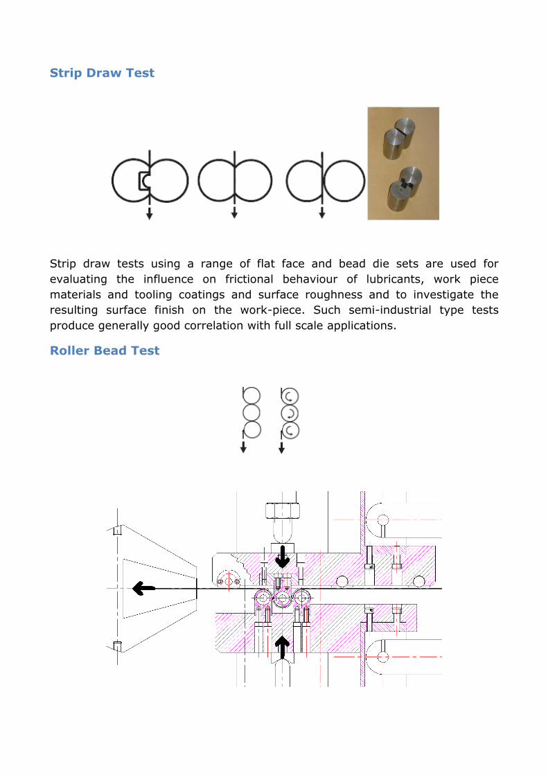
Strip Draw Test
Strip draw tests using a range of flat face and bead die sets are used for
evaluating the influence on frictional behaviour of lubricants, work piece
materials and tooling coatings and surface roughness and to investigate the
resulting surface finish on the work-piece. Such semi-industrial type tests
produce generally good correlation with full scale applications.
Roller Bead Test
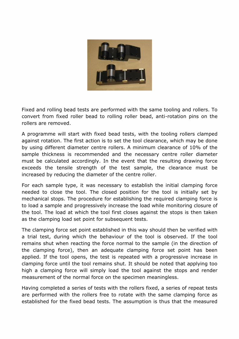
Fixed and rolling bead tests are performed with the same tooling and rollers. To
convert from fixed roller bead to rolling roller bead, anti-rotation pins on the
rollers are removed.
A programme will start with fixed bead tests, with the tooling rollers clamped
against rotation. The first action is to set the tool clearance, which may be done
by using different diameter centre rollers. A minimum clearance of 10% of the
sample thickness is recommended and the necessary centre roller diameter
must be calculated accordingly. In the event that the resulting drawing force
exceeds the tensile strength of the test sample, the clearance must be
increased by reducing the diameter of the centre roller.
For each sample type, it was necessary to establish the initial clamping force
needed to close the tool. The closed position for the tool is initially set by
mechanical stops. The procedure for establishing the required clamping force is
to load a sample and progressively increase the load while monitoring closure of
the tool. The load at which the tool first closes against the stops is then taken
as the clamping load set point for subsequent tests.
The clamping force set point established in this way should then be verified with
a trial test, during which the behaviour of the tool is observed. If the tool
remains shut when reacting the force normal to the sample (in the direction of
the clamping force), then an adequate clamping force set point has been
applied. If the tool opens, the test is repeated with a progressive increase in
clamping force until the tool remains shut. It should be noted that applying too
high a clamping force will simply load the tool against the stops and render
measurement of the normal force on the specimen meaningless.
Having completed a series of tests with the rollers fixed, a series of repeat tests
are performed with the rollers free to rotate with the same clamping force as
established for the fixed bead tests. The assumption is thus that the measured
drawing force with fixed rollers is the sum of the friction force in the tooling and
the deformation force, whereas with rotating rollers, the drawing force is the
deformation force only.
Friction coefficients for the test series may be calculated as follows:
μ = Drawing Force (Sliding) – Drawing Force (Rolling)
π x Clamping Force (Sliding)
Load Scanner
The load scanner is a concept developed by Professors Sture Hogmark and
Staffan Jacobson at Uppsala University. The device offers a new test
configuration for assessing the friction and wear properties of materials and
lubricants. Two elongated test specimens, preferably bars or rods, are used.
The orientation of the test specimens and their relative sliding motion during
testing is arranged in such a way that the contact spot moves along a contact
path on each specimen, and each spot along this path on one specimen will only
make contact to one spot on the other specimen, and vice verse. The contact
spot is the area over which the contact load is distributed.
The load is applied by means of a pulley mechanism and spring arrangement,
connected between the load arm and the lower specimen carriage. The loading
arrangement is such that the load increases or decreases with relative motion
of the specimens, thus resulting in a unique load at each unique contact point
on the two specimens.
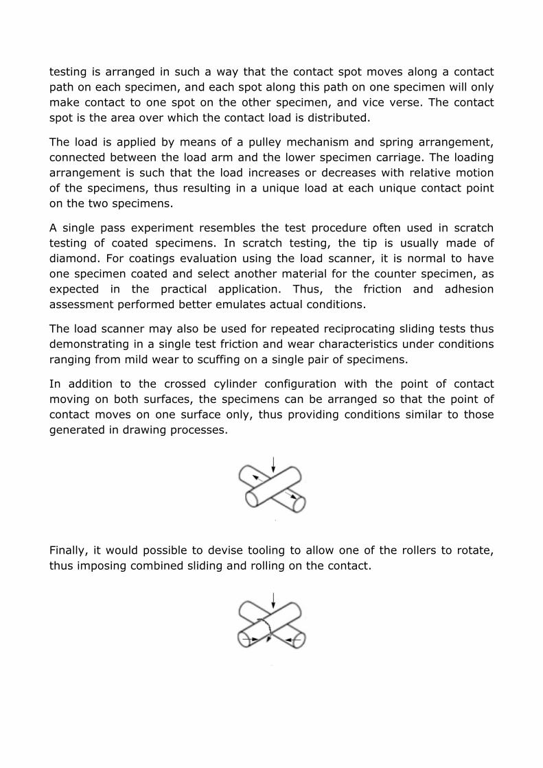
A single pass experiment resembles the test procedure often used in scratch
testing of coated specimens. In scratch testing, the tip is usually made of
diamond. For coatings evaluation using the load scanner, it is normal to have
one specimen coated and select another material for the counter specimen, as
expected in the practical application. Thus, the friction and adhesion
assessment performed better emulates actual conditions.
The load scanner may also be used for repeated reciprocating sliding tests thus
demonstrating in a single test friction and wear characteristics under conditions
ranging from mild wear to scuffing on a single pair of specimens.
In addition to the crossed cylinder configuration with the point of contact
moving on both surfaces, the specimens can be arranged so that the point of
contact moves on one surface only, thus providing conditions similar to those
generated in drawing processes.
Finally, it would possible to devise tooling to allow one of the rollers to rotate,
thus imposing combined sliding and rolling on the contact.
The load scanner probably represents the most novel tribometer concept in
recent years and is yet to be fully explored.
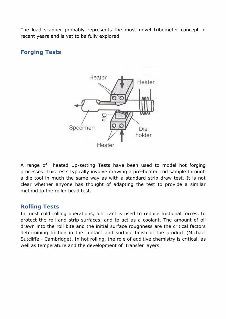
Forging Tests
A range of heated Up-setting Tests have been used to model hot forging
processes. This tests typically involve drawing a pre-heated rod sample through
a die tool in much the same way as with a standard strip draw test. It is not
clear whether anyone has thought of adapting the test to provide a similar
method to the roller bead test.
Rolling Tests
In most cold rolling operations, lubricant is used to reduce frictional forces, to
protect the roll and strip surfaces, and to act as a coolant. The amount of oil
drawn into the roll bite and the initial surface roughness are the critical factors
determining friction in the contact and surface finish of the product (Michael
Sutcliffe - Cambridge). In hot rolling, the role of additive chemistry is critical, as
well as temperature and the development of transfer layers.
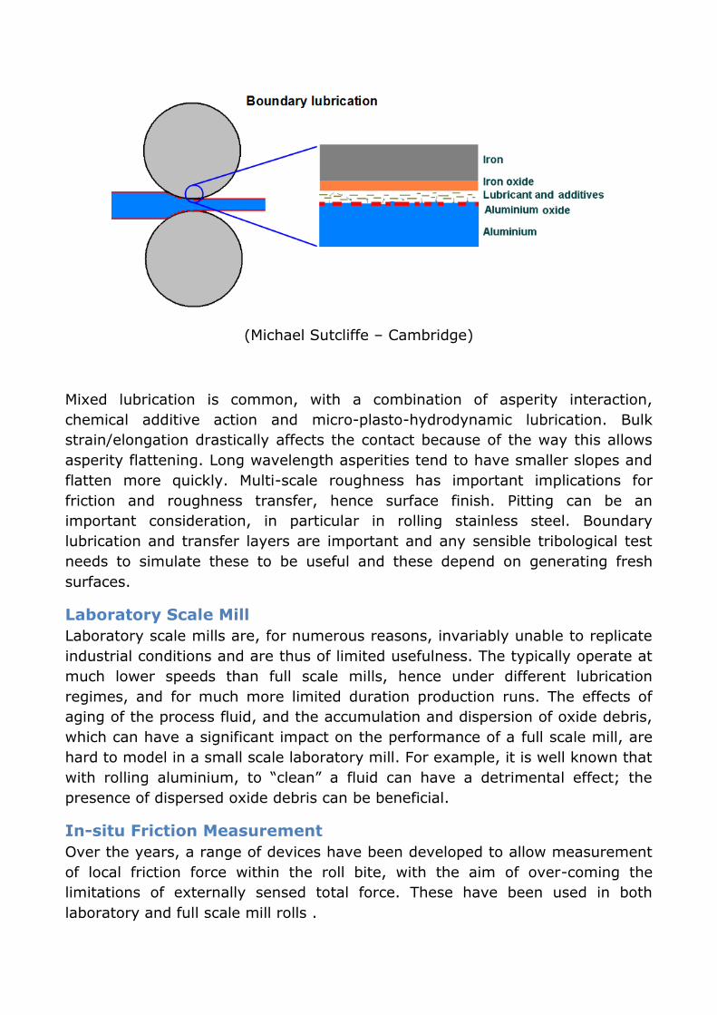
(Michael Sutcliffe – Cambridge)
Mixed lubrication is common, with a combination of asperity interaction,
chemical additive action and micro-plasto-hydrodynamic lubrication. Bulk
strain/elongation drastically affects the contact because of the way this allows
asperity flattening. Long wavelength asperities tend to have smaller slopes and
flatten more quickly. Multi-scale roughness has important implications for
friction and roughness transfer, hence surface finish. Pitting can be an
important consideration, in particular in rolling stainless steel. Boundary
lubrication and transfer layers are important and any sensible tribological test
needs to simulate these to be useful and these depend on generating fresh
surfaces.
Laboratory Scale Mill
Laboratory scale mills are, for numerous reasons, invariably unable to replicate
industrial conditions and are thus of limited usefulness. The typically operate at
much lower speeds than full scale mills, hence under different lubrication
regimes, and for much more limited duration production runs. The effects of
aging of the process fluid, and the accumulation and dispersion of oxide debris,
which can have a significant impact on the performance of a full scale mill, are
hard to model in a small scale laboratory mill. For example, it is well known that
with rolling aluminium, to “clean” a fluid can have a detrimental effect; the
presence of dispersed oxide debris can be beneficial.
In-situ Friction Measurement
Over the years, a range of devices have been developed to allow measurement
of local friction force within the roll bite, with the aim of over-coming the
limitations of externally sensed total force. These have been used in both
laboratory and full scale mill rolls .
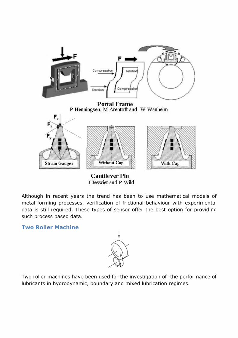
Although in recent years the trend has been to use mathematical models of
metal-forming processes, verification of frictional behaviour with experimental
data is still required. These types of sensor offer the best option for providing
such process based data.
Two Roller Machine
Two roller machines have been used for the investigation of the performance of
lubricants in hydrodynamic, boundary and mixed lubrication regimes.
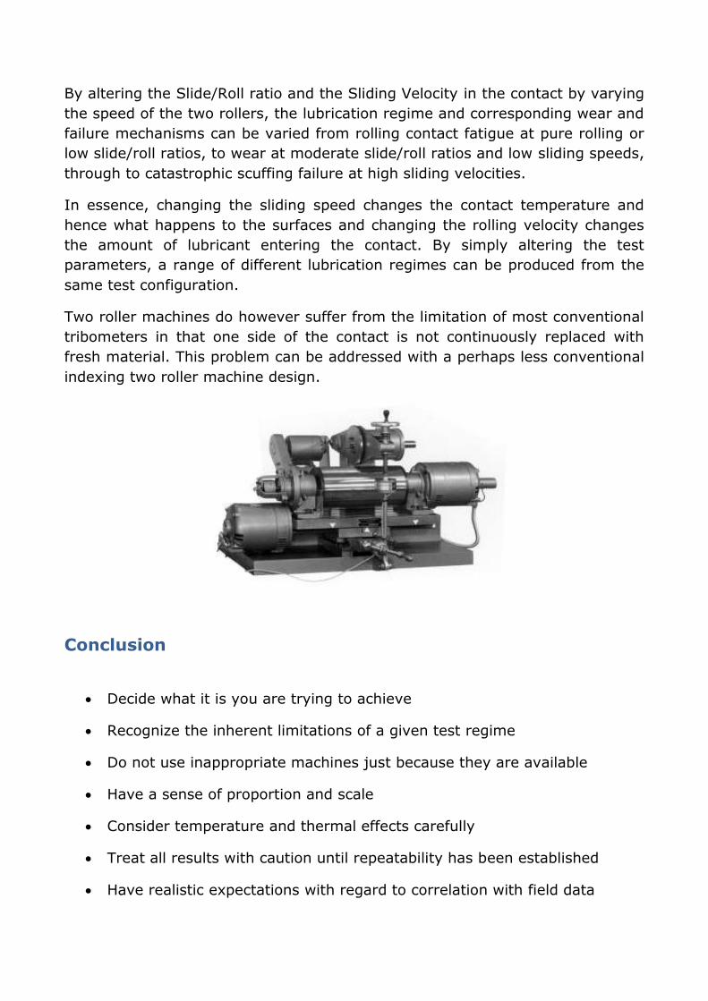
By altering the Slide/Roll ratio and the Sliding Velocity in the contact by varying
the speed of the two rollers, the lubrication regime and corresponding wear and
failure mechanisms can be varied from rolling contact fatigue at pure rolling or
low slide/roll ratios, to wear at moderate slide/roll ratios and low sliding speeds,
through to catastrophic scuffing failure at high sliding velocities.
In essence, changing the sliding speed changes the contact temperature and
hence what happens to the surfaces and changing the rolling velocity changes
the amount of lubricant entering the contact. By simply altering the test
parameters, a range of different lubrication regimes can be produced from the
same test configuration.
Two roller machines do however suffer from the limitation of most conventional
tribometers in that one side of the contact is not continuously replaced with
fresh material. This problem can be addressed with a perhaps less conventional
indexing two roller machine design.
Conclusion
Decide what it is you are trying to achieve
Recognize the inherent limitations of a given test regime
Do not use inappropriate machines just because they are available
Have a sense of proportion and scale
Consider temperature and thermal effects carefully
Treat all results with caution until repeatability has been established
Have realistic expectations with regard to correlation with field data