machining recommendations for semi-finished … recommendations for semi-finished engineering...
TRANSCRIPT
Machining Recommendations for Semi-Finished Engineering Plastics
Stock shapes
Processing of plastics (introduction)Differences between plastics and metals
Extrusion technology
Tools and machines
MachiningCutting
Turning
Milling
Drilling
Cutting threads
Planing / Plane milling
Grinding
Surface quality, reworking and de-burring
Machining guidelines
Interview with Hufschmied Zerspanungssysteme
Cooling and cooling lubricants
AnnealingMorphological changes and post-shrinkage
Dimensional stability
Product groups and material characteristicsTECAFORM AH / AD, TECAPET, TECAPEEK
TECAST T, TECAMID 6, TECAMID 66
TECANAT, TECASON, TECAPEI
TECA Materials with PTFE
TECASINT
Fibre reinforced materials
Special case of TECATEC
7 Machining errors - causes and solutionsCutting and sawing
Turning and milling
Drilling
4
5
6
6
7
8
9
9
10
11
11
12
13
15
16
18
19
20
21
22
22
22
23
23
23
24
25
26
26
26
27
Content

PI
PAI
PES, PPSUPEI, PSU
PPP, PC-HT
PCPA 6-3-T
PPE mod.
PMMA
PS, ABS, SAN
PEKEKKPEEK, PEKLCP, PPSPTFE, PFAETFE, PCTFEPVDF
PA 46PET, PBT PA 66PA 6, PA 11, PA 12POM
PMP
PP
PE
Polymer Abbreviation Ensinger Nomenclature Polymer Name
PI TECASINT Polyimide
PEEK TECAPEEK Polyether ether ketone
PPS TECATRON Polyphenylene sulphide
PPSU TECASON P Polyphenylsulphone
PES TECASON E Polyethersulphone
PEI TECAPEI Polyetherimide
PSU TECASON S Polysulphone
PTFE TECAFLON PTFE Polytetrafluoroethylene
PVDF TECAFLON PVDF Polyvinylidene fluoride
PA 6 C TECAST T Polyamide 6 cast
PA 66 TECAMID 66 Polyamide 66
PA 6 TECAMID 6 Polyamide 6
PC TECANAT Polycabonate
PBT HYDEX 4101 Polybutylene terephthalate
PET TECAPET Polyethylene terephthalate
PPE TECANYL Polyphenylene ether
POM-C TECAFORM AH Polyoxymethylene Copolymer
POM-H TECAFORM AD Polyoxymethylene Homopolymer
PMP TECAFINE PMP Polymethylpentene
Technical plastics
300 °F
572 °F
212 °F
amorphous
semi-crystalline
High-temperature plastics
Engineering plastics
Standard plastics
long term service temperature

4
Dimensionally stable, functional and durable components can be manufactured from plastics using professional machining and processing techniques. The general term “Plastic Processing” suggests that all plastics can be machined with the same parameters and tools. With metals, on the other hand, one speaks not only of “metal proces-sing”, but a difference is made between aluminium, steel or stainless steel. In an analogous way, it applies that the individual characteristics of plastic materials have to be taken into consideration when processing them.
The specific properties of plastics have a decisive influence
upon their machining ability. Materials can be classified
into different groups:
ˌ Amorphous thermoplastics
(e.g.: TECASON S, TECANAT)
ˌ Partly crystalline thermoplastics
(e.g.: TECAFORM, TECAPET, TECAPEEK)
ˌ Fibre reinforced thermoplastics
(e.g.: TECAPEEK PVX, TECAMID 6 GF 30,
TECAMID 66 CF20, TECADUR PBT GF 30)
ˌ Fabric reinforced thermoplastics
(e.g.: TECATEC PEEK CW 50)
ˌ PTFE modified thermoplastics
(e.g.: TECAPET TF, TECAPEEK TF10 blue)
Processing of plastics

5
Compared to metals, plastics have a wide range of benefits
to offer, although a number of restrictions must also be borne
in mind. Basically, the use of plastics is possible in those
areas where in particular a favourable ratio between weight
and strength is required.
Plastic offers a solution for applications calling for two to
three of the following characteristic benefits. However, in
order to be able to utilize the benefits of plastics when sub-
stituting other materials, the component may also have to
be redesigned.
p Benefits over metal ˌ Low density
ˌ Good noise and vibration damping
ˌ Electrical insulation or adjustable conductivity
ˌ Good chemical resistance
ˌ Scope for free design
ˌ Permeability to electromagnetic waves
ˌ Very good corrosion resistance
ˌ Thermal insulation
ˌ Application-specific modification possible
q Limitations compared to metal ˌ Relatively low thermal resistance
ˌ Greater thermal expansion
ˌ Lower mechanical characteristics
ˌ Poorer creep resistance
The above mentioned advantages and disadvantages of
plastics compared to metals are to be observed especially in
processes involving technical machining.
s To be noted: ˌ Good thermal insulation
ˌ Lower thermal conductivity
ˌ Heat is not or only partly dissipated via the machined
component, as in metal processing
ˌ Higher thermal expansion than metals
ˌ Good fixation and support of plastics in processing
s Possible consequences, if not observed ˌ Too much heat input in the component can lead to high
stress levels and thus to warping or fracture.
ˌ Excessive heat input causes expansion of the plastic.
The required tolerances of machined parts can thus not
be maintained
ˌ Inadequate fixation may lead to deformation during
machining
u Recommendations ˌ Good heat dissipation - best via the material chips -
as well as adequate fixation
This approach needs to be adapted depending on the
plastic, in order to establish the optimum cutting tools and
parameters for all thermoplastic materials. Only in this way
can optimum components be made. Detailed information
on the machining of plastic materials is available on the
following pages.
Differences between plastics and metal
6
Manufacturing processes, especially the extrusion of semi-
finished goods, have an impact on the properties and the
workability of a material.
Plastic semi-finished goods made of PTFE or polyimides
can be manufactured by compression and sintering. An
important processing technology for other thermoplastics
is the extrusion process. In this shaping process, materials
are melted and compressed in a cylinder via a screw conveyor
and homogenized. Using the pressure arising in the cy-
linder – and the appropriate tooling – semi-finished goods
are delivered in the form of sheets, round rods and tubes
and calibrated via a cooling system.
Impact ˌ Internal tension develops
ˌ Fibres take up a specific orientation (if available)
Ensinger offers a broad product portfolio of semi-finished
engineering plastics and high-temperature plastics. Stan-
dard plastic materials round off the portfolio. All these
materials are manufactured so they may be processed
optimally by machining.
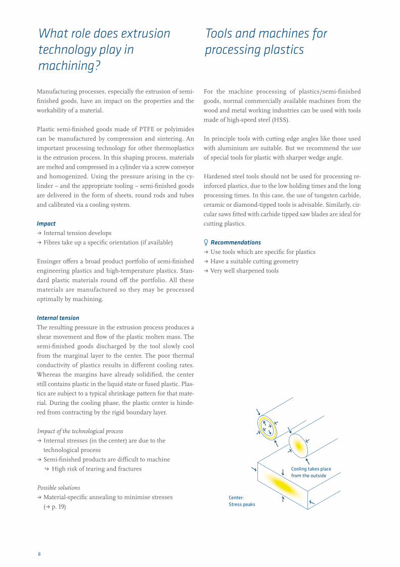
Internal tensionThe resulting pressure in the extrusion process produces a
shear movement and flow of the plastic molten mass. The
semi-finished goods discharged by the tool slowly cool
from the marginal layer to the center. The poor thermal
conductivity of plastics results in different cooling rates.
Whereas the margins have already solidified, the center
still contains plastic in the liquid state or fused plastic. Plas-
tics are subject to a typical shrinkage pattern for that mate-
rial. During the cooling phase, the plastic center is hinde-
red from contracting by the rigid boundary layer.
Impact of the technological process
ˌ Internal stresses (in the center) are due to the
technological process
ˌ Semi-finished products are difficult to machine
h High risk of tearing and fractures
Possible solutions
ˌ Material-specific annealing to minimise stresses
(ˌ p. 19)
For the machine processing of plastics/semi-finished
goods, normal commercially available machines from the
wood and metal working industries can be used with tools
made of high-speed steel (HSS).
In principle tools with cutting edge angles like those used
with aluminium are suitable. But we recommend the use
of special tools for plastic with sharper wedge angle.
Hardened steel tools should not be used for processing re-
inforced plastics, due to the low holding times and the long
processing times. In this case, the use of tungsten carbide,
ceramic or diamond-tipped tools is advisable. Similarly, cir-
cular saws fitted with carbide tipped saw blades are ideal for
cutting plastics.
u Recommendations ˌ Use tools which are specific for plastics
ˌ Have a suitable cutting geometry
ˌ Very well sharpened tools
Cooling takes place from the outside
What role does extrusion technology play in machining?
Tools and machines for processing plastics
Center:Stress peaks
7
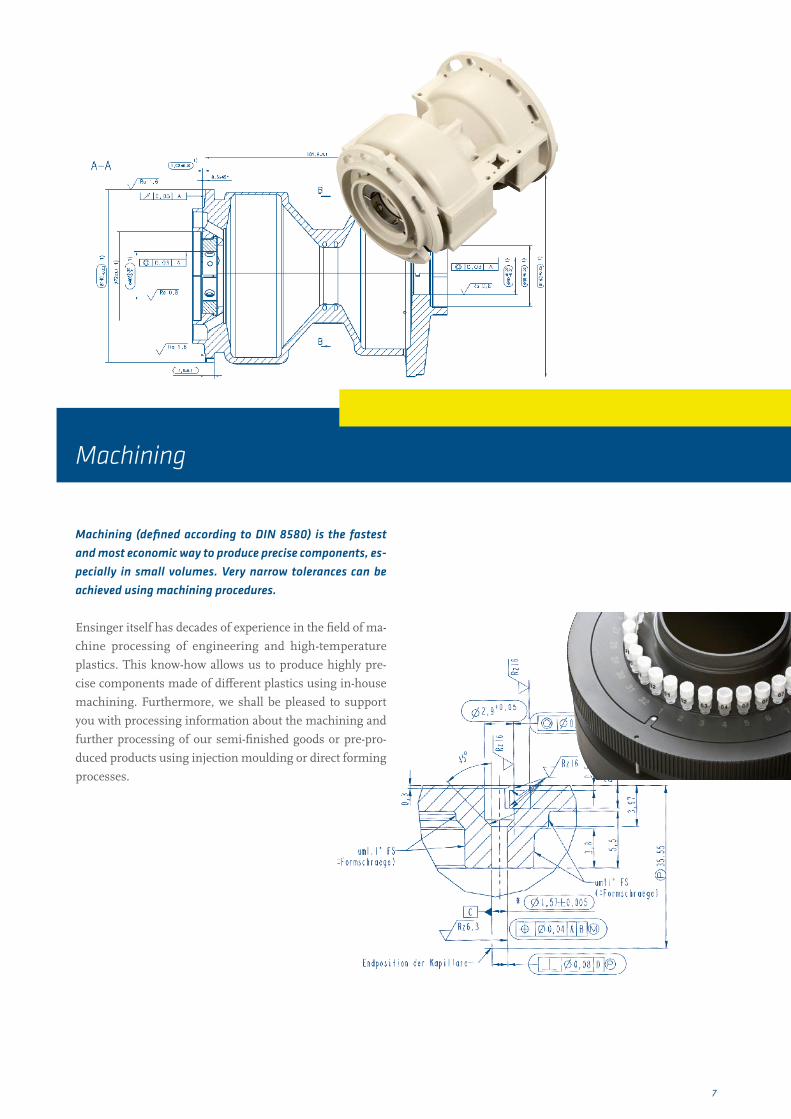
Machining (defined according to DIN 8580) is the fastest and most economic way to produce precise components, es-pecially in small volumes. Very narrow tolerances can be achieved using machining procedures.
Ensinger itself has decades of experience in the field of ma-
chine processing of engineering and high-temperature
plastics. This know-how allows us to produce highly pre-
cise components made of different plastics using in-house
machining. Furthermore, we shall be pleased to support
you with processing information about the machining and
further processing of our semi-finished goods or pre-pro-
duced products using injection moulding or direct forming
processes.
Machining
8
φ
γ
γ
tα
αφ
α
γ
α
γ
χ
Sägen
Bohren
Fräsen
Drehen
β
Circular saws ˌ Mainly suited for cutting plates to size with straight
cutting edges
ˌ Table circular saws can be used with the right power
drive for straight cuts of plates with thicknesses of
up to 4"
ˌ Saw blades should be made of hardened metal
ˌ Use a sufficiently high enough feed rate and adequate
offset
h Leads to good chip deflection
hAvoids sticking of the saw blade
hAvoids overheating of the plastic in the saw cut
hLeads to good cutting edge quality
u Recommendations ˌ Use a corresponding tensioning device:
hAvoidance of vibrations and unclean cutting edges
which can result from this, or even lead to breakage
ˌ Warm cutting of very hard and fibre-reinforced
materials (preheat to 175 – 250 °F)
ˌ Tungsten carbide saw blades wear well and provide an
optimum surface finish
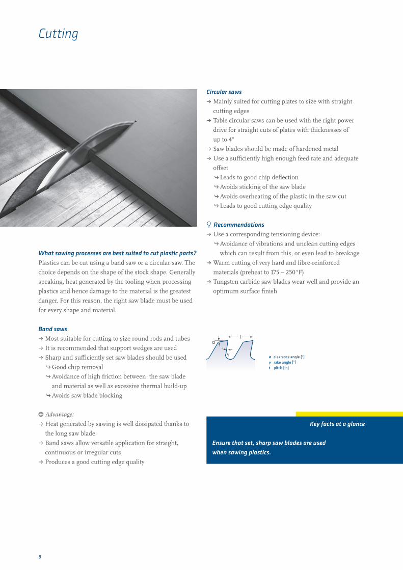
What sawing processes are best suited to cut plastic parts? Plastics can be cut using a band saw or a circular saw. The
choice depends on the shape of the stock shape. Generally
speaking, heat generated by the tooling when processing
plastics and hence damage to the material is the greatest
danger. For this reason, the right saw blade must be used
for every shape and material.
Band saws ˌ Most suitable for cutting to size round rods and tubes
ˌ It is recommended that support wedges are used
ˌ Sharp and sufficiently set saw blades should be used
hGood chip removal
h Avoidance of high friction between the saw blade
and material as well as excessive thermal build-up
hAvoids saw blade blocking
p Advantage:
ˌ Heat generated by sawing is well dissipated thanks to
the long saw blade
ˌ Band saws allow versatile application for straight,
continuous or irregular cuts
ˌ Produces a good cutting edge quality
Cutting
Key facts at a glance
Ensure that set, sharp saw blades are used when sawing plastics.
α clearance angle [°] γ rake angle [°]t pitch [in]

9
Plastics can be processed on commercially available lathes.
For optimal results, however, specific plastic cutters should
be used.
Cutting tools ˌ Use tools with small cutting radii
ˌ Broad-nosed finishing cutting edge for high quality
finish requirements
ˌ Knifelike cutting geometries for machining flexible
workpieces
ˌ Use favourable geometries for fixing
ˌ Special chisel geometry for parting off
ˌ Cut circumferences and polished surfaces
p Advantage:
ˌ Optimal, groove-less surface
ˌ Reduces the build-up of material on the application
u Recommendations ˌ Select a high cutting speed
ˌ Use a cutting depth of at least 0.020"
ˌ Compressed air is well suited for cooling
ˌ Use of a lunette due to reduced rigidity of plastics
hStabilize the component
hAvoidance of deformation
p Advantage:
ˌ Good cooling of the material
ˌ Overcomes flow chipping which can arise with some
plastics. Prevents jamming and rotating with the lathe
part of the blade
Plastics can be milled using customary machining centres.
This should be done using tools with adequate chip space
in order to guarantee reliable discharge of chips and
prevent overheating.
Tools ˌ Suitable for thermoplastics
hSlot milling cutter
hFace milling cutter
hCylindrical milling cutter
hSingle cutter tools
hFly cutter
ˌ Single cutter tools
p Advantage:
hOptimal average high cutting performance
hHigh surface quality with good chip removal at the
same time
u Recommendations ˌ High cutting speeds and medium feed rates
ˌ Ensure good attachment:
hRapid method for the table and a high spindle speed
coupled with correct fixture alignment lead to higher
quality machined finish
ˌ Thin work-pieces can be secured using a suction fixture
or dual-sided adhesive tape on the router table
ˌ For flat surfaces, end milling is more economical than
peripheral milling
ˌ During peripheral milling, tools should not have more
than two cutting edges in order to minimize vibrations
caused by a high number of cutting edges, and chip
spaces should be adequately dimensioned
ˌ Stepped milling is recommended where heat
accumulation has to be avoided by improved heat
dissipation
How better milling surfaces can be achieved ˌ For surface milling, choose a low chip angle
ˌ Optimal cutting performance and surface qualities
result from single cutter tools
ˌ Down milling should be used in preference to
conventional milling
How are plastics best processed on a lathe? (turning)
Milling recommendations
Trimming Cutting chisel
Polished section avoids scrap
10
When drilling plastic components, select a method suitable
for plastic materials in order to avoid defects. Otherwise,
there is a danger of breaking, tearing, overheating or
dimensional deviations of the drill holes.
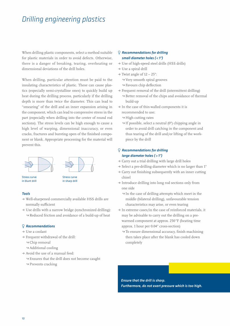
When drilling, particular attention must be paid to the
insulating characteristics of plastic. These can cause plas-
tics (especially semi-crystalline ones) to quickly build up
heat during the drilling process, particularly if the drilling
depth is more than twice the diameter. This can lead to
“smearing” of the drill and an inner expansion arising in
the component, which can lead to compressive stress in the
part (especially when drilling into the center of round rod
sections). The stress levels can be high enough to cause a
high level of warping, dimensional inaccuracy, or even
cracks, fractures and bursting open of the finished compo-
nent or blank. Appropriate processing for the material will
prevent this.
Tools ˌ Well-sharpened commercially available HSS drills are
normally sufficient
ˌ Use drills with a narrow bridge (synchronized drilling):
h Reduced friction and avoidance of a build-up of heat
u Recommendations ˌ Use a coolant
ˌ Frequent withdrawal of the drill:
hChip removal
hAdditional cooling
ˌ Avoid the use of a manual feed:
hEnsures that the drill does not become caught
hPrevents cracking
u Recommendations for drilling small diameter holes ( < 1")
ˌ Use of high-speed steel drills (HSS drills)
ˌ Use a spiral drill
ˌ Twist angle of 12 – 25°:
h Very smooth spiral grooves
hFavours chip deflection
ˌ Frequent removal of the drill (intermittent drilling)
h Better removal of the chips and avoidance of thermal
build-up
ˌ In the case of thin-walled components it is
recommended to use:
hHigh cutting rates
h If possible, select a neutral (0°) chipping angle in
order to avoid drill catching in the component and
thus tearing of the drill and/or lifting of the work-
piece by the drill
u Recommendations for drilling large diameter holes ( > 1")
ˌ Carry out a trial drilling with large drill holes
ˌ Select a pre-drilling diameter which is no larger than 1"
ˌ Carry out finishing subsequently with an inner cutting
chisel
ˌ Introduce drilling into long rod sections only from
one side
h In the case of drilling attempts which meet in the
middle (bilateral drilling), unfavourable tension
characteristics may arise, or even tearing
ˌ In extreme cases/in the case of reinforced materials, it
may be advisable to carry out the drilling on a pre-
warmed component at approx. 250 °F (heating time
approx. 1 hour per 0.04" cross-section)
hTo ensure dimensional accuracy, finish machining
then takes place after the blank has cooled down
completely
Drilling engineering plastics
Key facts at a glance
Ensure that the drill is sharp. Furthermore, do not exert pressure which is too high.
Stress curve in blunt drill
Stress curve in sharp drill

11
Fräshobeln HobelnFräshobeln Hobeln
Threads are best introduced into engineering plastics using
chasing tools for male threads or milling for female threads.
Tools ˌ Use of a chasing tools
ˌ Two-dentate chaser avoids burr formation
ˌ Dies are not recommended. In the case of a return,
re-cutting is possible
u Recommendations ˌ Taps often have to be provided with an allowance
(dependent upon material and diameter, approx.
value: 0.004")
ˌ Do not select a pre-setting which is too high,
in order to avoid squashing of the thread
Planing and plane milling are chip production methods
with geometrically determined cutting for the manufacture
of certain cuts to produce equal surfaces, grooves or pro-
files (using shaping milling).
Both procedures differ only in that with planing a straight
line of material removal is made across the surface using a
planing machine cutting tool. In the case of plane milling,
on the other hand, the surface is processed using a milling
head. Both processes are well-suited to produce even and/
or equalized surfaces on semi-finished goods. The main
difference is that optically different surfaces arise (surface
structure, gloss).
Cutting threads Planing / plane milling
Planed surface
Planing
Milled surface
Plane milling

12
Sägen Hobeln
Schleifen Formhobeln
In grinding, the overall effect of cutting, work-piece, delive-
ry and feed movements results in a continuous chip remo-
val from the surface being processed. The grinding result is
influenced by
ˌ the grinding machine
ˌ the tool being used
ˌ the grinding medium
ˌ the working parameters of the grinding process
ˌ the material to be processed
ˌ the roundness/straightness of the semi-finished goods
Particularly decisive working parameters are:
ˌ cutting speed
ˌ forward rate of advance
ˌ delivery
ˌ cross-sectional advance rate
Optimally adjusted machinery and the right choice of para-
meters for the corresponding material ensure that very
good surface quality with slight roughness, roundness
and straightness can be achieved.
Grinding at EnsingerWe are able to provide ground round rods via our cutting
service. Thanks to a high surface quality and narrow tole-
rances, ground round rods are easily further processed and
are suitable for continuous production processes.
Grinding

13
To obtain a good surface quality, the following guidelines
should be followed:
Tools ˌ Tools suitable for plastics must be used
ˌ Tools must always be well sharpened and smooth
(sharpened cutting edge). Blunt cutting edges can lead
to increased heat generation, resulting in distortion and
thermal expansion
ˌ Tools should be adequately spaced to ensure that only
the cutting edge comes into contact with the plastic
Processing machine ˌ Flawless, high-quality finished surfaces can only be
achieved with low-vibration machine running
Material ˌ Use low-tension annealed material (semi-finished
goods from Ensinger are generally low-tension
annealed)
ˌ Note the properties of the plastic (thermal expansion,
low strength, poor heat conduction ...)
ˌ Due to the minimal rigidity of the material, the work-
piece must be adequately supported and lie as flat as
possible on the supporting surface in order to avoid
deflection and out-of-tolerance results
Cooling ˌ Use coolants for processes involving the generation of
high levels of heat (such as drilling)
ˌ Use suitable coolants
u Recommendations ˌ Tension pressures must not be too high, as otherwise
deformations and impression marks can result on the
work-piece
ˌ Select suitable parameters for the machining process
(ˌ p. 15)
ˌ Keep feed rate to a moderate level
ˌ Select a high cutting speed
ˌ Good removal of chips must be guaranteed in order to
prevent tool congestion
ˌ Ensure that chip removal is equal on all sides in order
to prevent warping
Surface quality, reworking and de-burring

14
De-burringAfter milling, grinding, drilling, turning or engraving, a
small piece of the material to be processed remains on the
work-piece or its edges. This flash negatively influences the
quality of the surface of the component. In plastics proces-
sing, burr formation depends in particular on a number of
different parameters.
Tooling
ˌ Select tooling which is specific for a particular material
ˌ Condition of the tool:
h Blunt tools cause a much higher level of heat
development and burr formation
Material
ˌ Poor thermally conducting plastics:
hLocal increased temperatures, reduction
of rigidity and hardness
hMelting burrs/flash
ˌ There is a tendency for soft, tough plastics
(e.g.: PE, PTFE) to show more burr formation; hard,
stiffer materials (e.g.: PEEK, PPS, fibre-reinforced
material) less
Processing parameters
ˌ Material advancement rate
ˌ Cutting speed:
hHigher advancement rates and cutting speeds lead to
higher temperatures
hGreater burr formation
ˌ Ensure adequate cooling
For the reasons mentioned, it is important to select a
suitable tool for each material and to establish the right
parameters, in order to achieve the best possible and flash-
free surfaces and edges.
Typical de-burring methods for engineering plastics
Manual de-burring
ˌ Most common method of de-burring
ˌ Flexible, but most work intensive
ˌ At the same time, visual control of the component can
be performed
Jet de-burring
Jet of abrasive material at high pressure used on the surface
of the component; common blasting methods: sand, glass
balls, soda, dry-ice and nutshell blasting
ˌ Also, represents surface treatment methods
h Smoothing
hRoughening
hRemoval of contamination
Cryogenic de-burring
Removal of burrs at temperatures around –320 °F via the
use of a jet or drum tumbling of the components
ˌ Frequent coolants: liquid oxygen, liquid carbon dioxide,
dry-ice
ˌ Low temperatures lead to brittleness and hardness of
the materials
Flame de-burring
De-burring using an open flame
ˌ Danger: damage may be caused to the component due
to excessive heat development
Hot-air de-burring
The flash melts under the influence of heat
ˌ Very safe and well controllable process
ˌ Avoidance of damage or warping of the component
when using process management suitable for the
material
Infrared de-burring
Process is comparable to hot-air de-burring, instead of hot
air, an infrared heat source is used for heating
Rumbling / Trovalising
Treating the parts together with abrasives in rotating /
vibrating

15
TECAFINE PE, PP Z1 – Z2 250 – 500 0,1 – 0,45 6 – 10 0 – 5 45 – 60 250 – 500 0,1 – 0,5TECAFINE PMP Z1 – Z2 250 – 500 0,1 – 0,45 6 – 10 0 – 5 45 – 60 250 – 500 0,1 – 0,5TECARAN ABS Z1 – Z2 300 – 500 0,1 – 0,45 5 – 15 25 – 30 15 200 – 500 0,2 – 0,5TECANYL Z1 – Z2 300 0,15 – 0,5 5 – 10 6 – 8 45 – 60 300 0,1 – 0,5TECAFORM AD, AH Z1 – Z2 300 0,15 – 0,5 6 – 8 0 – 5 45 – 60 300 – 600 0,1 – 0,4TECAMID, TECARIM, TECAST Z1 – Z2 250 – 500 0,1 – 0,45 6 – 10 0 – 5 45 – 60 250 – 500 0,1 – 0,5TECADUR/TECAPET Z1 – Z2 300 0,15 – 0,5 5 – 10 0 – 5 45 – 60 300 – 400 0,2 – 0,4TECANAT Z1 – Z2 300 0,15 – 0,4 5 – 10 6 – 8 45 – 60 300 0,1 – 0,5TECAFLON PTFE, PVDF Z1 – Z2 150 – 500 0,1 – 0,45 5 – 10 5 – 8 10 150 – 500 0,1 – 0,3TECAPEI Z1 – Z2 250 – 500 0,1 – 0,45 10 0 45 – 60 350 – 400 0,1 – 0,3TECASON S, P, E Z1 – Z2 250 – 500 0,1 – 0,45 6 0 45 – 60 350 – 400 0,1 – 0,3TECATRON Z1 – Z2 250 – 500 0,1 – 0,45 6 0 – 5 45 – 60 250 – 500 0,1 – 0,5TECAPEEK Z1 – Z2 250 – 500 0,1 – 0,45 6 – 8 0 – 5 45 – 60 250 – 500 0,1 – 0,5TECATOR Z1 – Z2 60 – 100 0,05 – 0,35 6 – 8 0 – 5 7 – 10 100 – 120 0,05 – 0,08TECASINT Z1 – Z2 90 – 100 0,05 – 0,35 2 – 5 0 – 5 7 – 10 100 – 120 0,05 – 0,08
Z1 – Z2 80 – 450 0,05 – 0,4 6 – 8 2 – 8 45 – 60 150 – 200 0,1 – 0,5
TECAFINE PE, PP 20 – 30 2 – 5 500 3 – 8 Z2 25 90 50 – 150 0,1 – 0,3TECAFINE PMP 20 – 30 2 – 5 500 3 – 8 Z2 25 90 50 – 150 0,1 – 0,3TECARAN ABS 15 – 30 0 – 5 300 2 – 8 Z2 25 90 50 – 200 0,2 – 0,3TECANYL 15 – 30 5 – 8 300 3 – 8 Z2 25 90 50 – 100 0,2 – 0,3TECAFORM AD, AH 20 – 30 0 – 5 500 – 800 2 – 5 Z2 25 90 50 – 150 0,1 – 0,3TECAMID, TECARIM, TECAST 20 – 30 2 – 5 500 3 – 8 Z2 25 90 50 – 150 0,1 – 0,3TECADUR/TECAPET 15 – 30 5 – 8 300 3 – 8 Z2 25 90 50 – 100 0,2 – 0,3TECANAT 15 – 30 5 – 8 300 3 – 8 Z2 25 90 50 – 100 0,2 – 0,3TECAFLON PTFE, PVDF 20 – 30 5 – 8 300 2 – 5 Z2 25 90 150 – 200 0,1 – 0,3TECAPEI 15 – 30 0 – 4 500 2 – 5 Z2 25 90 20 – 80 0,1 – 0,3TECASON S, P, E 15 – 30 0 – 4 500 2 – 5 Z2 25 90 20 – 80 0,1 – 0,3TECATRON 15 – 30 0 – 5 500 – 800 3 – 5 Z2 25 90 50 – 200 0,1 – 0,3TECAPEEK 15 – 30 0 – 5 500 – 800 3 – 5 Z2 25 90 50 – 200 0,1 – 0,3TECATOR 15 – 30 0 – 3 800 – 900 10 – 14 Z2 25 90 80 – 100 0,02 – 0,1TECASINT 5 – 10 0 – 3 800 – 900 3 – 4 Z2 25 120 80 – 100 0,02 – 0,1
15 – 30 10 – 15 200 – 300 3 – 5 Z2 25 100 80 – 100 0,1 – 0,3φ
γ
γ
tα
αφ
α
γ
α
γ
χ
Sägen
Bohren
Fräsen
Drehen
β
φ
γ
γ
tα
αφ
α
γ
α
γ
χ
Sägen
Bohren
Fräsen
Drehen
β
φ
γ
γ
tα
αφ
α
γ
α
γ
χ
Sägen
Bohren
Fräsen
Drehen
β
φ
γ
γ
tα
αφ
α
γ
α
γ
χ
Sägen
Bohren
Fräsen
Drehen
β
Machining Guidelines
Preheat material to 250 °F Caution when using coolants:
susceptible to stress cracking
* Reinforcing agents/fillers: Glass fibres, glass beads, carbon fibres, graphite, mica, talcum, etc.
Milling Turning
number of teeth
cutting speed [fpm]
feed rate [in/rev]
clearance angle
rake angle
side angle
cutting speed [fpm]
feed rate [in/rev]
Z1 – Z2 820 – 1640 0.004 – 0.018 6 – 10 0 – 5 45 – 60 820 – 1640 0.004 – 0.018Z1 – Z2 820 – 1640 0.004 – 0.018 6 – 10 0 – 5 45 – 60 820 – 1640 0.004 – 0.018Z1 – Z2 985 – 1640 0.004 – 0.018 5 – 15 25 – 30 15 655 – 1640 0.008 – 0.018Z1 – Z2 985 0.006 – 0.018 5 – 10 6 – 8 45 – 60 985 0.004 – 0.018Z1 – Z2 985 0.006 – 0.018 6 – 8 0 – 5 45 – 60 985 – 1700 0.004 – 0.016Z1 – Z2 820 – 1640 0.004 – 0.018 6 – 10 0 – 5 45 – 60 820 – 1640 0.004 – 0.018Z1 – Z2 985 0.006 – 0.018 5 – 10 0 – 5 45 – 60 985 – 1310 0.008 – 0.016Z1 – Z2 985 0.006 – 0.016 5 – 10 6 – 8 45 – 60 985 0.004 – 0.018Z1 – Z2 490 – 1640 0.004 – 0.018 5 – 10 5 – 8 10 490 – 1640 0.004 – 0.012Z1 – Z2 820 – 1640 0.004 – 0.018 10 0 45 – 60 1150 – 1310 0.004 – 0.012Z1 – Z2 820 – 1640 0.004 – 0.018 6 0 45 – 60 1150 – 1310 0.004 – 0.012Z1 – Z2 820 – 1640 0.004 – 0.018 6 0 – 5 45 – 60 820 – 1640 0.004 – 0.018Z1 – Z2 820 – 1640 0.004 – 0.018 6 – 8 0 – 5 45 – 60 820 – 1640 0.004 – 0.018Z1 – Z2 197 – 325 0.002 – 0.014 6 – 8 0 – 5 7 – 10 325 – 395 0.002 – 0.003Z1 – Z2 295 – 325 0.002 – 0.014 2 – 5 0 – 5 7 – 10 325 – 395 0.002 – 0.003
Reinforced/filled TECA products* Z1 – Z2 260 – 1475 0.002 – 0.016 6 – 8 2 – 8 45 – 60 490 – 655 0.004 – 0.018
α clearance angle [°] γ rake angle [°]χ side angle [°]
The nose radius r must be at least 0.02"
α clearance angle [°] γ rake angle [°]
Tangential feed
Feed rate can be up to 0.02" / tooth
Sawing Drilling
clearance angle
rake angle
cutting speed [fpm ] pitch [in]
number of teeth
twist angle
rake angle
cutting speed [fpm ]
feed rate [in/rev]
20 – 30 2 – 5 1640 0.12 – 0.32 Z2 25 90 165 – 490 0.004 – 0.11820 – 30 2 – 5 1640 0.12 – 0.32 Z2 25 90 165 – 490 0.004 – 0.11815 – 30 0 – 5 985 0.08 – 0.32 Z2 25 90 165 – 650 0.008 – 0.11815 – 30 5 – 8 985 0.12 – 0.32 Z2 25 90 165 – 328 0.008 – 0.11820 – 30 0 – 5 1640 – 2625 0.08 – 0.20 Z2 25 90 165 – 490 0.004 – 0.11820 – 30 2 – 5 1640 0.12 – 0.32 Z2 25 90 165 – 490 0.004 – 0.11815 – 30 5 – 8 985 0.12 – 0.32 Z2 25 90 165 – 328 0.008 – 0.11815 – 30 5 – 8 985 0.12 – 0.32 Z2 25 90 165 – 328 0.008 – 0.11820 – 30 5 – 8 985 0.08 – 0.20 Z2 25 90 490 – 650 0.004 – 0.11815 – 30 0 – 4 1640 0.08 – 0.20 Z2 25 90 65 – 260 0.004 – 0.11815 – 30 0 – 4 1640 0.08 – 0.20 Z2 25 90 65 – 260 0.004 – 0.11815 – 30 0 – 5 1640 – 2625 0.12 – 0.20 Z2 25 90 165 – 650 0.004 – 0.11815 – 30 0 – 5 1640 – 2625 0.12 – 0.20 Z2 25 90 165 – 650 0.004 – 0.11815 – 30 0 – 3 2625 – 2950 0.40 – 0.55 Z2 25 90 260 – 328 0.001 – 0.004 5 – 10 0 – 3 2625 – 2950 0.12 – 0.16 Z2 25 120 260 – 328 0.001 – 0.004
Reinforced/filled TECA products* 15 – 30 10 – 15 650 – 985 0.12 – 0.20 Z2 25 100 260 – 328 0.004 – 0.118
Heat before sawing:from 2.25" TECAPEEK GF/PVX, TECATRON GF/PVXfrom 3" TECAMID 66 GF, TECAPET, TECADUR PBT GFfrom 4" TECAMID 6 GF, 66, 66 MDS
* Reinforcing agents/fillers: Glass fibres, glass beads, carbon fibres, graphite, mica, talcum, etc.
Heat before drilling in the center:from 2.25" TECAPEEK GF/PVX, TECATRON GF/PVXfrom 3" TECAMID 66 MH, 66 GF, TECAPET, TECADUR PBT GFfrom 4" TECAMID 6 GF, 66, TECAM 6 MO, TECANYL GF
α clearance angle [°] γ rake angle [°]t pitch [in]
α clearance angle [°] β twist angle [°] γ rake angle [°]φ point angle [°]

16
Interview: with Hufschmied Zerspanungssysteme
What is the business of the Hufschmied Company?Hufschmied is specialised in the development and manu-
facture of “material-optimized machining tools” for the
field of plastics and composites. Our tooling is manufactu-
red in-house using CNC 6-axis grinding centres. In this
way, short throughput times are possible from the enquiry
to the delivery. High-grade fully hardened metals and cera-
mics serve as the basic materials, which are coated accor-
ding to the requirements of the customer.
What is your experience in the field of machining plastics in general?Hufschmied has been present in the market for more than
25 years. Very early on we have concentrated on the machi-
ning of plastics, as it was evident that this is where high
growth was to be expected. Plastics continue to develop
rapidly and new high-tech materials are added to the mar-
ket every day. As we work with different material manu-
facturers and universities, we always have the possibility to
come into contact at a very early stage with novel materials.
These are then machined in our own laboratory. In this
way, we can support our customers at an early stage with
appropriate tools and processes.
How do you react to the new challanges involved with the new materials?To date, we have been able to machine all plastics, even if
sometimes several optimization loops were needed for the
tooling. Plastics are becoming more diverse, so that we need
to adjust the tool geometries accordingly. A material data
sheet is helpful, especially with "filled" materials. As we do
not manufacture the plastics ourselves and are not able to
analyze them in every detail, we have to be able to rely on
this information. If these then fit the general conditions
such as machine set-up, tools and parameters, we are able to
achieve the desired result fairly quickly. All our trial results
are brought together in a knowledge database and analyzed.
This database is a cornerstone of our processing knowledge
and supports us in the tool and process development.
Process development
What philosophy do you follow in plastics processing?We always design our plastic tooling for dry machining. It
is relatively seldom that we are able to machine under "wet"
conditions: The application or the purpose of the compo-
nent often does not allow this.
Additives are included in all coolants and can adverse reac-
tions during the machining of plastics and additives. Our
tools are designed for machining at high feed rates. High
feed rates are used to ensure that there is no temperature
dissipated into the component, but into the chips. These
parameter adjustments are often made on site, because the
customer does not want to risk “cutting corners” due to a
lack of experience.
What do you see as the main problems in the plastics processing market?In my opinion, the customer is still focused too much on
the metalworking industry. This often results in problems
with "smeared" effects, warpage, cracking or burr formati-
on. In particular, the burr formation is a concern for our
customers, as this makes a lot of reworking time necessary.
We often then change only a few essential small things in
the machining program to avoid rework. Many customers
want a universal tool with which a majority of components
and materials can be processed. Unfortunately, this is rare-
ly possible, since different materials also require respective
tool geometries. The tool has to be adapted especially for
high-end applications, to match the material and the part.
Only in this way is appropriate processing possible which is
reliable and cost-effective.
Good / economic
part
Material
Programming
Machine
Tool clamping
Rotation speed(max. possible)
Tool

17
Which plastics in your opinion are from a technical machining point of view particularly critical or non-critical in their workability?Carbon or glass-fibre filled plastics are definitely challen-
ging. Currently, more and more plastics with ceramic fillers
are being used. This can make life difficult for a tool! But if
we know what is contained in the material, we can respond
accordingly. Materials such as PE, POM, PC, and PTFE can
be handled without any major problems arising with the
right tools, the right parameters and a good machine. But
the framework of conditions must also agree in detail.
Do you have a specific recommendation how to determine the optimum machining method for plastics?I need to know definitely how the machine works. How it
copes with small radii or rapid feed rates? If this has all
been determined, I can refer to the drawings, go to the
available speeds, feed rates and work-piece clamping on the
selected tool. As soon as the tools are defined, the programs
can be adapted. Basic values can be found on our home-
page www.hufschmied.net. The counter rotation is always a
big issue in this respect. Many people program the machi-
ne – as used in the processing of steel – in counter rotation
and then have major problems with burrs and a poor sur-
face finish.
Are there industries where the special needs in plastics processing have to be particularly taken into account?Every industry has its own terms of reference to which we
have to adapt ourselves. For example, the medical device in-
dustry. Dry machining is mostly carried out here. Very small
parts also often have to be produced. These usually require
special tools. We often work with micro-drills and extreme
lengths in cutting. On smooth surfaces a minimum depth
of roughness has to be produced. A small advantage is that
highly accurately working machines are used.
What properties do you take as a benchmark to determine the machining ability of plastics?In order to limit the machinability to some extent, we
mostly need the following details:
ˌ Material identification which is as accurate as possible
ˌ Is the material filled or further modified?
ˌ Does the material come from a rod or a sheet?
ˌ What is the final product to look like?
ˌ What machine is available?
ˌ How is the work-piece clamped?
Based on these statements, the machining ability can pos-
sibly be determined. We shall be pleased to also carry out
tests on our own machinery. In this respect, a test protocol
is prepared with parameters, photos and a demonstration
video.
What parameters can be used to optimise the machining processes?As already mentioned, the following parameters are impor-
tant for good machining:
ˌ Turning speed
ˌ Feed per tooth
ˌ The clamping of the work-piece and tool
ˌ Synchronised and counter rotation
ˌ Cooling
ˌ Program structure
The most important parameter is nevertheless the machi-
ning tool.
Ralph Hufschmied, Nabil Khairallah (Hufschmied Zerspa-
nungssysteme), interview by Holger Werz (Ensinger GmbH)
Softeningtemperature
Machining possible but with limited feed rates
t Problem area• Feathering• Cutter
breakage
High feed rateat high rotations• Economic
Machiningtemperature
Rotation speed
Temperature

18
Key facts at a glance
Generally speaking, dry processing is to be recommended with heat dissipation via the machining chips.
p Advantages of dry machining ˌ No media residues on the components
hAdvantageous for components used in medical
device technology or in the food industry
(no migration)
h Influence of cooling lubricants on the material can be
excluded. (Swelling, change of dimensions, tension
tearing, …)
hNo interaction with the material
hFalse assessment / treatment from machinist is
excluded
s Note ˌ especially with dry machining, cooling is essential to
achieve good dissipation of heat!
Currently there is a trend towards using dry machining with
engineering plastics. As there is now sufficient experience
available in this area, it is frequently possible to do without
the use of cooling lubricants. Exceptions for thermoplastic
machining processes are:
ˌ Deep drill holes
ˌ Thread cutting
ˌ Sawing reinforced materials
However, it is possible to use a cooled cutting surface to
improve both the surface quality and tolerances of the
machined plastic parts, and also to allow faster feed rates
and consequently reduced running times.
Machining with coolantsIf cooling is required, it is recommended to cool
ˌ Via the chippings
ˌ Using compressed air
hAdvantage: Cooling and removal of the chips at the
same time from the working area
ˌ Use of water soluble coolants
ˌ Commercially available drilling emulsions and cutting
oils can also be used
h Spray mist and compressed air are very effective
methods
Machining amorphous plastics
ˌ Avoid using coolants:
h Materials liable to develop tension tearing
ˌ If cooling is imperative:
h Parts should be rinsed in pure water or
isopropanol right after machining
hUse suitable coolants
ˌ Pure water
ˌ Compressed air
ˌ Special lubricants: Information about suitable
lubricants is available from your lubricant supplier
Cooling and cooling lubricants

19
Annealing
Annealing process The annealing process involves thermal treatment of semi-
finished goods, molded or finished parts. The products are
slowly and evenly warmed to a material specific, defined
temperature level. There then follows a holding period
which depends on the material and its thickness, in order
to thoroughly heat through the molded part. Subsequently
the material has to be slowly and evenly cooled back down
to room temperature.
Reducing tension by annealing ˌ Residual tensions, which have arisen during
manufacture or processing, can be extensively and
almost completely reduced by annealing
ˌ Increase in the crystallinity of materials
hOptimize mechanical material values
ˌ Formation of an even crystalline structure in materials
ˌ Partly improve the chemical resistance
ˌ Reduction of warping tendency and dimensional
changes (during or after processing)
ˌ Sustainable improvement in dimensional stability
Semi-finished goods at Ensinger are subjected to an anne-
aling step after production. In this way, it can be ensured
that the material that you receive will remain dimensionally
stable during and following processing and can also be
better processed by machining.
Intermediate annealingIt may also be wise to subject critical components to an
intermediate annealing step when processing. This applies
especially,
ˌ If narrow tolerances are required
ˌ If components with a strong tendency to warp due to
the required shape need to be produced (asymmetric,
narrowed cross-sections, pockets and grooves)
ˌ In the case of fibre-reinforced/filled materials (fibre
orientation can enhance warping)
hProcessing can lead to further, enhanced tension
being introduced into the component.
ˌ Use of blunt or unsuitable tools:
h Initiators of tension
ˌ Excessive heat input into the component – produced by
inappropriate speeds and feed rates
ˌ High stock removal volumes - primarily as a result of
one-sided machining
Material Polymer Abbreviation Heating-up phase Maintaining phase* Cooling down phase
TECASINT PI 2 h to 320 °F 6 h to 540 °F 2 h at 320 °F / 10 h at 540 °F at 30 °F / h to 100 °F
TECAPEEK PEEK 3 h to 250 °F 4 h to 430 °F 1,5 h per cm wall thickness at 30 °F / h to 100 °F
TECATRON PPS 3 h to 250 °F 4 h to 430 °F 1,5 h per cm wall thickness at 30 °F / h to 100 °F
TECASON E PES 3 h to 212 °F 4 h to 390 °F 1 h per cm wall thickness at 30 °F / h to 100 °F
TECASON P PPSU 3 h to 212 °F 4 h to 390 °F 1 h per cm wall thickness at 30 °F / h to 100 °F
TECASON S PSU 3 h to 212 °F 3 h to 330 °F 1 h per cm wall thickness at 30 °F / h to 100 °F
TECAFLON PVDF PVDF 3 h to 194 °F 3 h to 300 °F 1 h per cm wall thickness at 30 °F / h to 100 °F
TECANAT PC 3 h to 175 °F 3 h to 265 °F 1 h per cm wall thickness at 30 °F / h to 100 °F
TECAPET PET 3 h to 212 °F 4 h to 355 °F 1 h per cm wall thickness at 30 °F / h to 100 °F
HYDEX 4101 PBT 3 h to 212 °F 4 h to 355 °F 1 h per cm wall thickness at 30 °F / h to 100 °F
TECAMID 6 PA6 3 h to 194 °F 3 h to 320 °F 1 h per cm wall thickness at 30 °F / h to 100 °F
TECAMID 66 PA66 3 h to 212 °F 4 h to 355 °F 1 h per cm wall thickness at 30 °F / h to 100 °F
TECAFORM AH POM-C 3 h to 194 °F 3 h to 310 °F 1 h per cm wall thickness at 30 °F / h to 100 °F
TECAFORM AD POM-H 3 h to 194 °F 3 h to 320 °F 1 h per cm wall thickness at 30 °F / h to 100 °F
* At maximum temperature, unless otherwise specified.
20
Morphological changes and post-shrinkageThe heat treatment of plastics always has direct effects on
the materials and their processing:
ˌ Annealing
ˌ Machining (frictional heat)
ˌ Use (service temperature, hot steam sterilization)
Partially crystalline plastics
ˌ Annealing process leads to equalization of material
properties
h Increase in the crystallinity
hOptimization of mechanical properties
h Improved dimensional stability
hBetter chemical resistance
ˌ Machining can lead to local overheating through
frictional heat. Consequence:
hMicrostructural changes
hPost-shrinkage
ˌ Particularly critical in this respect is TECAFORM
h Improper machining can lead to severe deformation
and/or warping of the component
Amorphous plastics
ˌ Are less critical with regard to their post-shrinkage and
warping
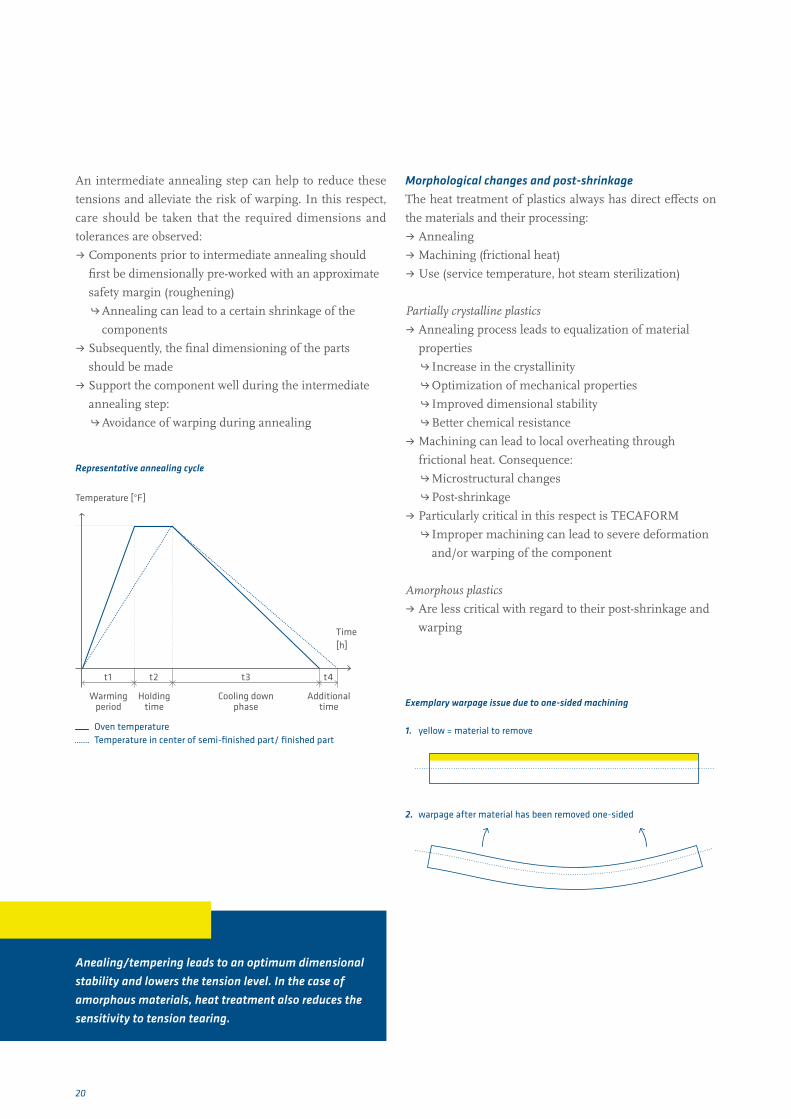
Exemplary warpage issue due to one-sided machining
1. yellow = material to remove
2. warpage after material has been removed one-sided
An intermediate annealing step can help to reduce these
tensions and alleviate the risk of warping. In this respect,
care should be taken that the required dimensions and
tolerances are observed:
ˌ Components prior to intermediate annealing should
first be dimensionally pre-worked with an approximate
safety margin (roughening)
h Annealing can lead to a certain shrinkage of the
components
ˌ Subsequently, the final dimensioning of the parts
should be made
ˌ Support the component well during the intermediate
annealing step:
hAvoidance of warping during annealing
Key facts at a glance
Anealing/tempering leads to an optimum dimensional stability and lowers the tension level. In the case of amorphous materials, heat treatment also reduces the sensitivity to tension tearing.
Time[h]
Temperature [°F]
Oven temperatureTemperature in center of semi-finished part/ finished part
Warming period
Holding time
Cooling down phase
Additional time
Representative annealing cycle
t1 t2 t3 t4

21
Dimensional stabilityDimensional stability is to be considered a characteristic in
every system in each process step – from the manufacture
of semi-finished plastics to the final end use. There are
various causes which can influence the dimensional stabi-
lity of a component.
Moisture uptake:
ˌ Plastics with lower moisture uptake are generally very
much more dimensionally stable. Example:
TECAFORM AH / AD, TECAPET, TECATRON,
TECAPEEK
h Can be achieved with narrow tolerances
ˌ Plastics with high levels of moisture uptake show a
marked influence on dimensional stability
Example: TECAMID, TECAST
h Moisture uptake/release leads to swelling or
shrinkage of the material
h Conditioning is possibly recommended prior to
processing
Tension relaxation
ˌ Internal or “frozen in” tension acts only partly or has
little effect on the dimensional stability of the finished
part during processing at room temperature.
hDimensionally stable finished part
ˌ During storage or in use, this “frozen in” tension can
break down
hDimensional changes.
ˌ Particularly critical: Use of components at higher
temperatures:
hTension can be reduced suddenly.
hChange of shape, warping or in the worst case
tension tearing when using the component
Heat input
ˌ All processes are critical in which heat develops in the
material
h Example: Annealing, machining, use at high
temperatures, sterilization
ˌ Temperatures above the glass transition temperature
have an effect on microstructural changes and thus
post-shrinkage after renewed cooling down
hShrinkage and warping are particularly apparent in
asymmetrical component geometries
h Partly crystalline thermoplastics exhibit high post-
shrinkage (up to ~1.0 – 2.5 %) and are critical with
regard to warping
h Amorphous thermoplastics show only slight post-
shrinkage characteristics (~0.3 – 0.7 %) and are more
dimensionally stable than partly crystalline thermo-
plastics
ˌ In many cases, higher thermal expansion (compared to
metal) must be taken into consideration
u Processing
ˌ Ensure good heat dissipation in order to avoid local
temperature rise
ˌ In the case of higher machining volumes it may be
advisable to introduce an intermediate annealing step,
in order to reduce the development of tension
ˌ Plastics require greater production tolerances than metals
ˌ Avoid higher tensional forces, in order to avoid distortion
ˌ In the case of fibre-reinforced materials in particular,
attention should be paid to the position of the
component in the semi-finished goods (observe
extrusion direction)
ˌ When machining, a component optimized procedure
should be chosen

22
TECAFORM AH / AD,TECAPET, TECAPEEKSemi-crystalline, unreinforced materialsTECAFORM AH / AD, TECAPET and TECAPEEK are very
dimensionally stable materials with balanced mechanical
properties. These materials are very easy to machine and
basically tend to produce short chips. They can be machi-
ned with very high delivery and high feed rates.
Fundamentally, however, it is important to pay attention
during processing to a low heat input as far as possible, as
TECAFORM as well as TECAPET in particular have a high
tendency to undergo post-shrinkage by up to ~2.5 % -
warping can arise thereby due to local overheating.
In the case of the materials mentioned above, very low sur-
face roughness can be achieved with optimized machining
parameters.
TECAST T, TECAMID 6, TECAMID 66 (Polyamides)Unreinforced PolyamidesIt should generally be remembered with polyamides:
TECAST T, TECAMID 6 and TECAMID 66 are materials
based on polyamides. Contrary to the previously men tioned
materials, it should be remembered that polyamides have
naturally very brittle characteristics – this may also be re-
ferred to in the context of a “freshly molded” condition.
Due to their chemical structure, the polyamides tend, how-
ever, to absorb moisture - this property gives the polyamides
their very good balance between toughness and strength.
The moisture uptake via the surface leads to a virtually
constant distribution of water content over the entire cross
section with small semi-finished dimensions and compo-
nents. In the case of larger dimensioned semi-finished
goods (in particular for round rods/sheets of 4" diameter /
wall thickness upwards) the moisture content decreases
from the outside inwards.
In the most unfavorable case, the center is of a brittle and
hard character. Added to the internal tension produced by
extrusion technology, machining can carry a certain risk of
producing tension cracking.
In addition, it should be remembered that as a consequence
moisture uptake can change the dimensions of the material.
This “swelling” has to be allowed for in the processing and
design of components made of polyamide. The moisture
uptake (conditioning) of semi-finished goods plays an im-
portant part in the case of machining. Especially thin-
walled components (up to ~0.40") can absorb up to 3 %
moisture. As a rule of thumb:
ˌ A moisture uptake of 3 % causes a dimensional change
of about 0.5 % !
Machining of TECAST T
ˌ Tends to produce short chips
ˌ Is therefore good to machine
Machining of TECAMID 6 and TECAMID 66
ˌ Form a flow of chips
ˌ More frequent removal of chips from the tool/work-
piece can be necessary
ˌ Important in order to generate chips which break off
when they are very short and to avoid breakdowns in
the process:
h Ideal machining parameters
hChoice of suitable tools
Generally speaking, we recommend pre-heating to 175 –
250 °F with larger dimensioned work-pieces (e.g. round
rods > 4" and sheets with a wall thickness > 3") and machi-
ning close to the center, in order to avoid tension cracking
during processing.
Product groups and material characteristics
Key facts at a glance
Amorphous plastics should be dry machined as far as possible. If the use of a cooling lubricant is absolutely necessary, the component should be subsequently cleaned immediately afterwards.

23
TECANAT, TECASON,TECAPEI Amorphous thermoplasticsTECANAT, TECASON, TECAPEI are amorphous materials,
which are very prone to develop tension cracking in contact
with aggressive media, such as oils and fats. Also, cooling
lubricants often contain media, which can trigger tension
in the material. For this reason, avoid using cooling lub-
ricants when machining these materials as far as possible
or, for example, a water-based medium should be used.
Similarly, material specific machining parameters should
be selected as far as possible.
ˌ Do not use feed rates which are too high
ˌ Avoid the use of higher pressures
ˌ Avoid excessively high tensions
ˌ Preferably select a higher rotational speed
ˌ Use suitably sharp tools
s To be observed with construction designs
Construction designs should be adapted to match amor-
phous materials.
ˌ Avoid shearing forces (constructive and in processing)
ˌ Design edges/geometries according to the type of
material (preferably choose inner edges which are
slightly rounded-off)
The materials can be used to manufacture very dimen-
sionally stable prefabricated parts with very narrow toleran-
ces, taking suitable machining parameters into account.
TECA materials with PTFEMaterials containing a PTFE component (e.g. TECAFLON
PTFE, TECAPEEK TF, TECAPEEK PVX, TECATRON PVX,
TECAPET TF, TECAFORM AD AF) frequently exhibit
slightly lower mechanical strength. Due to this PTFE content,
several aspects should be remembered when processing.
s Pay attention to the following when machining these materials:
ˌ Materials tend to lag behind the milling tool
hThere is a distinct increase in surface roughness
(hair formation, spikes, rough surface)
ˌ Avoid re-cutting with the milling machine
hAlso leads to rougher surfaces
ˌ A further “re-cutting process” may be necessary in order
to smooth spikes to the desired surface quality
ˌ De-burring is often also necessary
Select a suitable tension, in order to avoid the component
“dying away” and as a result components that are not true
to size.
TECASINTPolyimide products produced by a sintering processThe TECASINT product groups 1000, 2000, 3000, 4000 and
5000 can be processed dry or wet on standard metal wor-
king machinery.
s Recommendations
Tools
ˌ Use fully hardened metal tools
ˌ Tools with a cutting angle as used for aluminium
processing are very suitable
ˌ For highly filled TECASINT products with e.g. glass
fibres, glass beads, use tools fitted with diamond or
ceramic tips
Processing
ˌ High cutting speeds and low feed rates coupled with
dry machining improve the result
ˌ Wet processing increases the cutting pressure and
promotes the formation of flash, but is recommended
to extend the tool life
ˌ Synchronous milling to prevent chipping and cavities
ˌ Intermediate tempering is normally not necessary
s Due to the increased tendency of polyimides to absorb mois-
ture, it is advisable to seal these parts in a vacuum barrier film.
In order to avoid dimensional changes to very high quality parts
due to moisture absorption, these are opened just before use.

24
Fibre reinforcedTECA materialsFibre reinforced materials include all types of fibres.
We are concentrating on the most important products in
these machining recommendations, including carbon-fibre
reinforced products (amongst others, TECAPEEK GF30,
TECAPEEK CF30, TECAPEEK PVX, TECATRON GF40,
TECTRON PVX, TECAMID 66 GF30, TECAMID 66 CF20)
and glass-fibre reinforced products.
u RecommendationsTooling
ˌ Use hardened steel tools (carbide steel K20) in any case,
or ideally polycrystalline diamond tooling (PCD)
ˌ Use very well sharpened tools
ˌ Regular control checks of tools, due to the abrasive
effects of the materials
hHigher standing times
hAvoid too much temperature input
Clamping semi-finished goods
ˌ Clamp in the extrusion direction (highest compression
strength)
ˌ Use the lowest possible tensions
hAvoid sagging and flexural strain
hReduced warping and/or the danger of tension
cracking in the component
Pre-heating
ˌ Pre-heating of semi-finished goods may be
recommended for their further processing
hGreater material durability
ˌ Semi-finished goods should be moderately heated for
this purpose
ˌ We recommend a heating rate of 30 °F per hour to
175 – 250 °F.
ˌ For even temperature distribution in the semi-finished
goods cross-section, we also recommend a holding time
of at least 1 hour per 0.40" wall thickness.
ˌ At this temperature, the semi-finished parts should be
prefabricated with oversize
ˌ Final manufacture after cooling down to room
temperature
ˌ Tooling should also be heated before processing
hAvoid heat dissipation from the material
Processing
ˌ Even fly-cutting of the bilateral edge zones of the
semi-finished part:
h Ideally, each fly-cutting process should have a max.
cutting depth of 0.02"
hResults in more homogenous distribution of tension
in the semi-finished part
hLeads to a higher quality of the component
Example
We recommend, for example, with final dimensions of 1"
to use a 1.25" thick sheet, which is to be fly cut 0.125" on
both sides prior to machining. In this case, the sheet should
be turned over several times and max. 0.020" removed per
working step. Ideally, this preliminary work should be car-
ried out on a pre-warmed semi-finished part. Subsequently,
the final processing is carried out on the cooled, pre-pro-
cessed product. This process ensures in any case an opti-
mal component quality with low tension and minimum
warping of the component.
Key facts at a glance
For better tooling stand times and dimensional stability, the use of carbide steel or PCD tools is recommended with fibre reinforced materials.

25
Special case TECATEC
CompositeTECATEC is a composite based on a polyarylether ketone
with 50 and/or 60 % by weight carbon fibre fabric. The
machining of TECATEC is considerably more complex
than the machining of short fibre-reinforced products. Due
to the layer structure of the material, incorrect machining
can lead to different effects:
ˌ Edge chipping
ˌ De-lamination
ˌ Fringing
ˌ Breaking through of fibres
For this reason, specific processing is required for this
material. This has to be established case for case, according
to the component in question.
Design of semi-finished goods
The suitability of TECATEC for a certain use and the quality
of the finished part primarily depends upon the position of
the component in the semi-finished part. In the develop-
ment phase, the directionality of the fibre fabric must already
be urgently considered, especially with regard to the type of
load (pulling, compression, bending) on the application
and the later machine processing.
Machining tools and tooling materials
For higher standing times in comparison to HSS or carbide
steel tools, we recommend the use of
ˌ PCD tools (polycrystalline diamond)
ˌ Ceramic tools
ˌ Titanium coated tools
ˌ Tools with functional coatings (plasma technology)
Besides higher standing times, these tools help to minimise
the feed forces, when the specific material is also conside-
red in the design.
ˌ Select a moderate cutting sharpness
ˌ Establish a good balance between surface quality (with
very sharp blades) and tooling standing times (blunter
cutting blades)
ˌ Design milling geometries so that the fibres are cut.
Otherwise there is a danger of fibre fringing
ˌ Due to the higher abrasiveness of the carbon fibres,
regular changing of the TECATEC tools is necessary
h Avoid too much heat input and warping due to
blunt tools
Machining
ˌ There is a greater risk of chipping and burr formation
during the machining process with the fibres running
parallel to the woven fabric than when processing is
vertically to the woven fabric
ˌ For narrower tolerances, the components can also be
tempered several times during manufacture
ˌ Due to relatively good heat dissipation thanks to the
higher fibre content, good heat distribution in the work
piece can be expected. For this reason, we recommend
that the material be dry machined.
Machining and tooling parameters
We recommend that attention is paid to the following
parameters:
ˌ Avoid using high feed forces
ˌ Very high point angles (150 – 180°)
ˌ Very low feed rates (approx. < 0.002"/min)
ˌ High cutting rates (approx. 980 – 1,300 ft/min)
This information is intended to provide initial assistance in
the machining of TECATEC - detailed information depends
on the individual case.
26
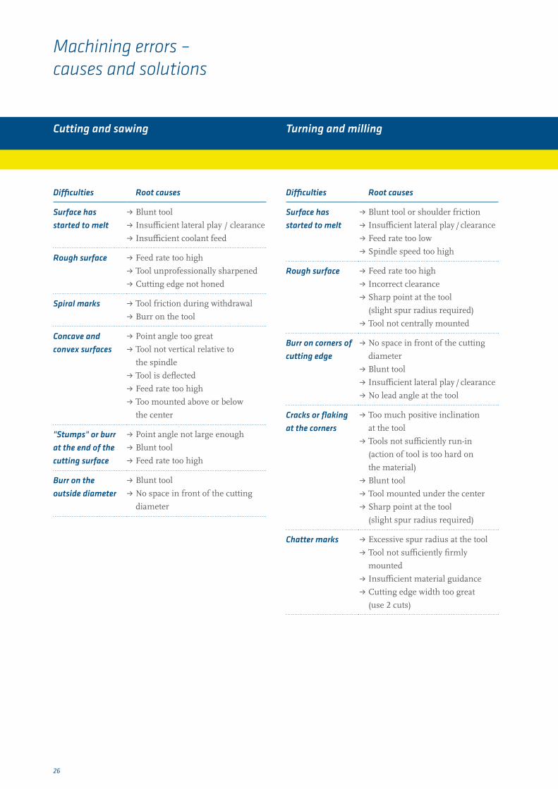
Machining errors – causes and solutions
Cutting and sawing Turning and milling
Difficulties Root causes
Surface has started to melt
ˌ Blunt tool
ˌ Insufficient lateral play / clearance
ˌ Insufficient coolant feed
Rough surface ˌ Feed rate too high
ˌ Tool unprofessionally sharpened
ˌ Cutting edge not honed
Spiral marks ˌ Tool friction during withdrawal
ˌ Burr on the tool
Concave and convex surfaces
ˌ Point angle too great
ˌ Tool not vertical relative to
the spindle
ˌ Tool is deflected
ˌ Feed rate too high
ˌ Too mounted above or below
the center
"Stumps" or burr at the end of the cutting surface
ˌ Point angle not large enough
ˌ Blunt tool
ˌ Feed rate too high
Burr on the outside diameter
ˌ Blunt tool
ˌ No space in front of the cutting
diameter
Difficulties Root causes
Surface has started to melt
ˌ Blunt tool or shoulder friction
ˌ Insufficient lateral play / clearance
ˌ Feed rate too low
ˌ Spindle speed too high
Rough surface ˌ Feed rate too high
ˌ Incorrect clearance
ˌ Sharp point at the tool
(slight spur radius required)
ˌ Tool not centrally mounted
Burr on corners of cutting edge
ˌ No space in front of the cutting
diameter
ˌ Blunt tool
ˌ Insufficient lateral play / clearance
ˌ No lead angle at the tool
Cracks or flaking at the corners
ˌ Too much positive inclination
at the tool
ˌ Tools not sufficiently run-in
(action of tool is too hard on
the material)
ˌ Blunt tool
ˌ Tool mounted under the center
ˌ Sharp point at the tool
(slight spur radius required)
Chatter marks ˌ Excessive spur radius at the tool
ˌ Tool not sufficiently firmly
mounted
ˌ Insufficient material guidance
ˌ Cutting edge width too great
(use 2 cuts)

27
Drilling
Difficulties Root causes
Tapered drill holes ˌ Incorrectly sharpened drill bits
ˌ Insufficient play / clearance
ˌ Excessively high feed rate
Burnt or melted surface
ˌ Use of unsuitable drill bits
ˌ Incorrectly sharpened drill bits
ˌ Insufficient feed rate
ˌ Blunt drill bit
ˌ Land too thick
Surface splitting ˌ Excessive feed rate
ˌ Excessive play / clearance
ˌ Excessive incline (thin land as
described)
Chatter marks ˌ Excessive play / clearance
ˌ Insufficient feed rate
ˌ Drill overhang too great
ˌ Excessive incline (thin land as
described)
Feed marks or spiral lines at the inside diameter
ˌ Excessively high feed rate
ˌ Drill not centred
ˌ Drill tip not in center
Overdimensioned drill holes
ˌ Drill tip not in center
ˌ Land too thick
ˌ Insufficient play / clearance
ˌ Excessively high feed rate
ˌ Drill point angle too great
Underdimensioned drill holes
ˌ Blunt drill bit
ˌ Excessive play / clearance
ˌ Drill point angle too small
Difficulties Root causes
Nonconcentric drill holes
ˌ Excessively high feed rate
ˌ Spindle speed too low
ˌ Drill penetrates too far into
next part
ˌ Parting-off tool leaves "stump"
which deflects the drill bit
ˌ Land too thick
ˌ Drilling speed too high at the start
ˌ Drill not clamped centrally
ˌ Drill not correctly sharpened
Burr left after parting off
ˌ Blunt cutting tools
ˌ Drill does not travel completely
through the part
Drill quickly becomes blunt
ˌ Feed rate too low
ˌ Spindle speed too low
ˌ Insufficient lubrication due to
cooling
Key facts at a glance
Please do not hesitate to contact our technical application advise service for technical information by telephone on 800-896-4029
Ensinger Germany
Ensinger GmbH Rudolf-Diesel-Straße 8 71154 Nufringen Tel. +49 7032 819 0 Fax +49 7032 819 100 www.ensinger-online.com
Ensinger GmbH Mercedesstraße 21 72108 Rottenburg a. N. Tel. +49 7457 9467 100 Fax +49 7457 9467 122 www.ensinger-online.com
Ensinger GmbH Wilfried-Ensinger-Straße 1 93413 Cham Tel. +49 9971 396 0 Fax +49 9971 396 570 www.ensinger-online.com
Ensinger GmbH Borsigstraße 7 59609 Anröchte Tel. +49 2947 9722 0 Fax +49 2947 9722 77 www.ensinger-online.com
Ensinger GmbH Mooswiesen 13 88214 Ravensburg Tel. +49 751 35452 0 Fax +49 751 35452 22 www.thermix.de
Ensinger worldwide
Austria Ensinger Sintimid GmbH Werkstraße 3 4860 Lenzing Tel. +43 7672 7012800 Fax +43 7672 96865 www.ensinger-sintimid.at
Brazil Ensinger Indústria de Plásticos Técnicos Ltda. Av. São Borja 3185 93.032-000 São Leopoldo-RS Tel. +55 51 35798800 Fax +55 51 35882804 www.ensinger.com.br
China Ensinger (China) Co., Ltd. 1F, Building A3 No. 1528 Gumei Road Shanghai 200233 P.R.China Tel. +86 21 52285111 Fax +86 21 52285222 www.ensinger-china.com
Czech Republic Ensinger s.r.o. Prùmyslová 991 P.O. Box 15 33441 Dobřany Tel. +420 37 7972056 Fax +420 37 7972059 www.ensinger.cz
Denmark Ensinger Danmark Rugvænget 6 4100 Ringsted Tel. +45 7810 4410 Fax +45 7810 4420 www.ensinger.dk
France Ensinger France S.A.R.L. ZAC les Batterses ZI Nord 01700 Beynost Tel. +33 4 78553635 Fax +33 4 78556841 www.ensinger.fr
Italy Ensinger Italia S.r.l. Via Franco Tosi 1/3 20020 Olcella di Busto Garolfo Tel. +39 0331 568348 Fax +39 0331 567822 www.ensinger.it
Japan Ensinger Japan Co., Ltd. 3-5-1, Rinkaicho, Edogawa-ku, Tokyo 134-0086, Japan Tel. +81 3 5878 1903 Fax +81 3 5878 1904 www.ensinger.jp
Poland Ensinger Polska Sp. z o.o. ul. Spóldzielcza 2h 64-100 Leszno Tel. +48 65 5295810 Fax +48 65 5295811 www.ensinger.pl
Singapur Ensinger International GmbH (Singapore Branch) 63 Hillview Avenue # 04-07 Lam Soon Industrial Building Singapore 669569 Tel. +65 65524177 Fax +65 65525177 [email protected]
Spain Ensinger S.A. Girona, 21-27 08120 La Llagosta Barcelona Tel. +34 93 5745726 Fax +34 93 5742730 www.ensinger.es
Sweden Ensinger Sweden AB Stenvretsgatan 5 SE-749 40 Enköping Tel. +46 171 477 050 Fax +46 171 440 418 www.ensinger.se
United Kingdom Ensinger Limited Wilfried Way Tonyrefail Mid Glamorgan CF39 8JQ Tel. +44 1443 678400 Fax +44 1443 675777 www.ensinger.co.uk
USA Ensinger Inc. 365 Meadowlands Boulevard Washington, PA 15301 Tel. +1 724 746 6050 Fax +1 724 746 9209 www.ensinger-inc.com
09/1
2 E9
9110
75A0
04US
Thermoplastic engineering and high-performance plastics from Ensinger are used in almost every important sector of industry today. Their economy and performance benefits have seen them frequently supplant classically used materials.
www.ensinger-inc.com