macread studio for pavement design · and the other for flexible pavement design. ... base course...
TRANSCRIPT

Welcome to the next February 2015 edition of the Maccaferri MacNews.
This month we will be focusing on two of our design software programs. One is used for Fluid Drainage and the other for Flexible Pavement design. Our software is always free and available our website for easy downloading. Just register on our website (www.maccaferri-usa.com) to gain access to our documents and software library.
MacRead Studio for Pavement Design
Maccaferri developed the MacRead Studio 1.0 Pavement Design Suite to help engineers and designers create models for the proper strength and position of geogrids for road base/sub base stabilization
Geosynthetics are extensively used for the improvement of soil mechanical properties with the target to obtain a pavement sections able to carry higher/more loads; such effect is the results of the positive effect induced by the geosynthetic presence due to the following stabilizing mechanisms:
Base course lateral restraint mechanism for horizontal stresses generated by the soil self-weight
Base course lateral restraint mechanism for horizontal stresses generated by wheels loading
Tensioned membrane mechanism at the base or sub base - subgrade interface
The tensile stresses due to the soil self-weight and the tensioned membrane mechanism at the base or sub base - subgrade interface are static, while the tensile stresses induced by traffic load are dynamic/cyclic. However in each instance both static and dynamic stresses coexist.
The design methods presently available provide no/or insufficient indications about the number of required geogrids layers and the mechanical characteristics thereof. Hence a new design method has been developed which accounts the design of geogrids for road base/sub base stabilization, based on a 4 layers model: asphalt layers (binder and wearing course), in case of paved roads; base, sub base, subgrade.
Once the base and/or sub base thickness has been defined with one of the available methods in literature (AASHTO method, Giroud – Han method, Leng - Gabr method, etc.) it is already appropriate for providing the structural capacity of the road to resist the design number of wheel passages for the whole design life of the road. Given this thickness, by considering separately the effect of the static loads (soil self-weight and tensioned membrane mechanism) and the instant effect of wheel load, it is then possible to calculate the distribution of the horizontal tensile forces in the whole road structure and the overall tensile forces generated in each layer of geosynthetic, and then to select the appropriate geosynthetic for each layer based on a limit state criterion.
The proposed design method allows to set the number and the mechanical characteristics of geosynthetics layers required for absorbing the horizontal forces generated by self-weight, wheel load and membrane effect. Obviously, more important is the road structure we are designing and lower the design geosynthetic strain shall be: hence for important structures the geosynthetic strain may be limited to 2%, while for less important structures (or when the design conditions afford slightly larger deformations) 3%, 4% or5% geosynthetic strain may be acceptable.
Below is a Case History in South Africa where this method was used successfully.
Special Supplement for Geosynthetics 2015 February 2015 MacNews
CASE HISTORY: Unpaved Road Secunda – Mpumalanga (Republic of South Africa)
Design by Leng-Gabr + Geogrid Design
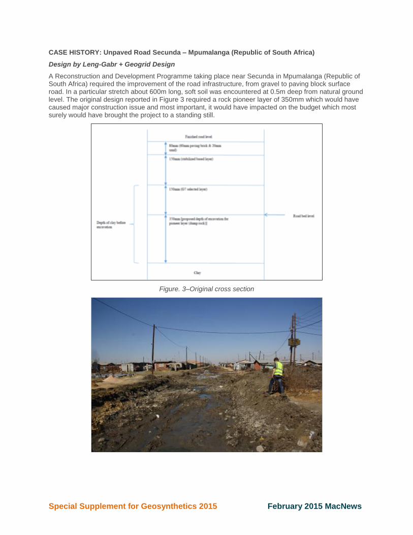
A Reconstruction and Development Programme taking place near Secunda in Mpumalanga (Republic of South Africa) required the improvement of the road infrastructure, from gravel to paving block surface road. In a particular stretch about 600m long, soft soil was encountered at 0.5m deep from natural ground level. The original design reported in Figure 3 required a rock pioneer layer of 350mm which would have caused major construction issue and most important, it would have impacted on the budget which most surely would have brought the project to a standing still.
Figure. 3–Original cross section
Special Supplement for Geosynthetics 2015 February 2015 MacNews
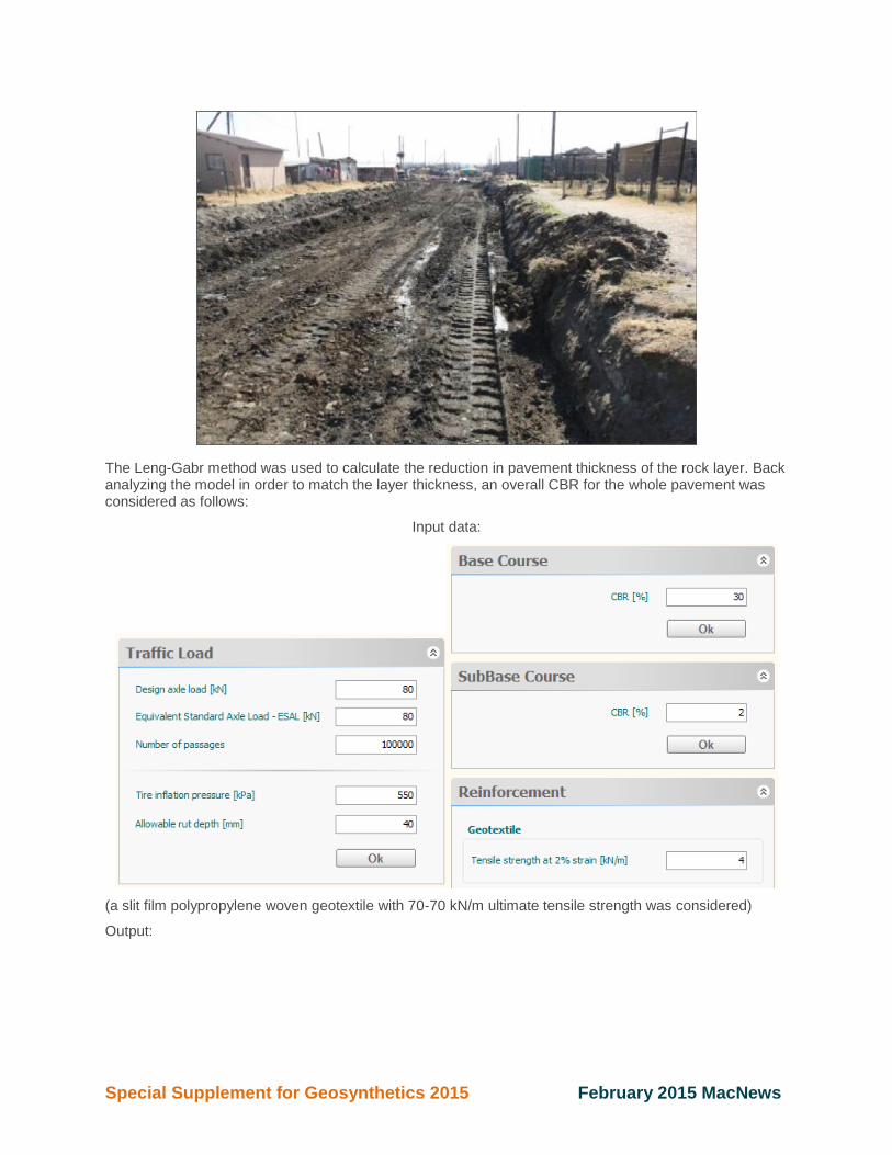
The Leng-Gabr method was used to calculate the reduction in pavement thickness of the rock layer. Back analyzing the model in order to match the layer thickness, an overall CBR for the whole pavement was considered as follows:
Input data:
(a slit film polypropylene woven geotextile with 70-70 kN/m ultimate tensile strength was considered)
Output:
Special Supplement for Geosynthetics 2015 February 2015 MacNews
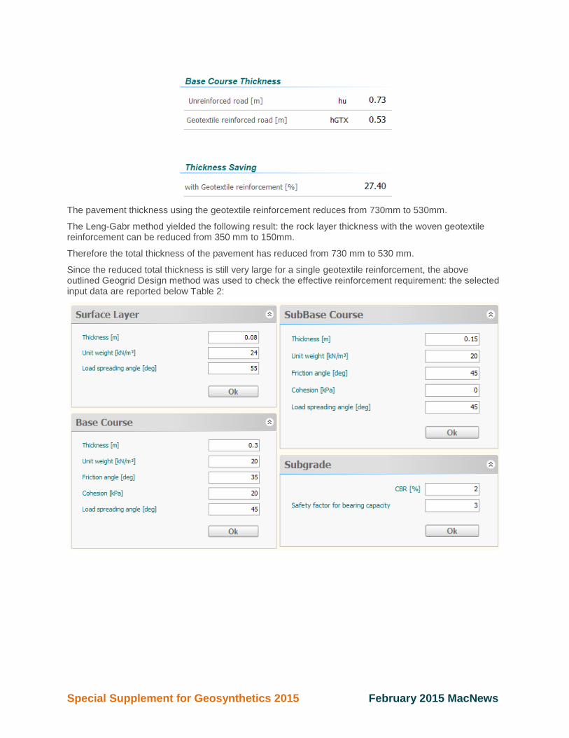
The pavement thickness using the geotextile reinforcement reduces from 730mm to 530mm.
The Leng-Gabr method yielded the following result: the rock layer thickness with the woven geotextile reinforcement can be reduced from 350 mm to 150mm.
Therefore the total thickness of the pavement has reduced from 730 mm to 530 mm.
Since the reduced total thickness is still very large for a single geotextile reinforcement, the above outlined Geogrid Design method was used to check the effective reinforcement requirement: the selected input data are reported below Table 2:
Special Supplement for Geosynthetics 2015 February 2015 MacNews
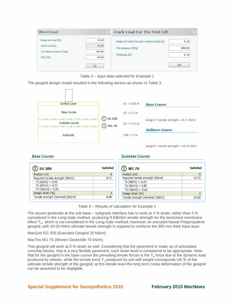
Table 2 – Input data selected for Example 1
The geogrid design model resulted in the following section as shown in Table 3.
Table 3 – Results of calculation for Example 1
The woven geotextile at the sub base – subgrade interface has to work at 3 % strain, rather than 2 % considered in the Leng-Gabr method, producing 9.63kN/m tensile strength for the tensioned membrane effect Tm, which is not considered in the Leng-Gabr method; moreover an extruded biaxial Polypropylene geogrid, with 20-20 kN/m ultimate tensile strength is required to reinforce the 300 mm thick base layer:
MacGrid EG 20S (Extruded Geogrid 20 kN/m);
MacTex W1 7S (Woven Geotextile 70 kN/m)
This geogrid will work at 3 % strain as well. Considering that the pavement is made up of articulated concrete blocks, that is a very flexible pavement; such strain level is considered to be appropriate. Note that for the geogrid in the base course the prevailing tensile forces is the Tp force due to the dynamic load produced by wheels, while the tensile force Tz produced by soil self-weight corresponds to5 % of the ultimate tensile strength of the geogrid; at this tensile level the long term creep deformation of the geogrid can be assumed to be negligible.

Special Supplement for Geosynthetics 2015 February 2015 MacNews
For the woven geotextile in the sub base the prevailing tensile force is the Tm force due to the tensioned membrane mechanism which, as above said, is developed during construction, without further development in time; the tensile force Tz produced by soil self-weight corresponds to 0.8 % of its ultimate tensile strength; at this tensile level the long term creep deformation of the geotextile can be assumed to be negligible.
MacFlow Studio for Drainage
Maccaferri has developed the MacFlow Studio software to facilitate the design of MacDrain® geocomposites. MacFlow Studio software has been engineered as an expert system, able to automatically select the appropriate geocomposites for any given project, and is presently the most advanced software for geocomposite design available on the market.
Used with our MacDrain® geocomposite, the fluids drain underground from one place to another and are composed by a draining core bonded - on one or both side - to filtering geotextiles. MacDrain® geocomposites are designed to replace traditional drainage materials such as gravels and sands.
MacFlow Studio software has been engineered as an expert system, able to automatically select the appropriate geocomposites for any given project, and is presently the most advanced software for geocomposite design available on the market.
MacFlow Suite is composed of 6 different modules:
MacFlow H: for the design of MacDrain® geocomposites in sub-horizontal applications
MacFlow S: for the design of MacDrain® geocomposites in sloping applications
MacFlow V: for the design of MacDrain® geocomposites in sub-vertical applications
Special Supplement for Geosynthetics 2015 February 2015 MacNews
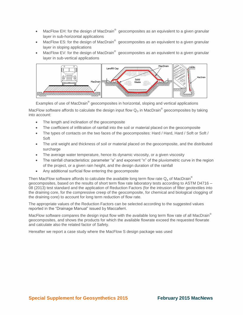
MacFlow EH: for the design of MacDrain® geocomposites as an equivalent to a given granular
layer in sub-horizontal applications
MacFlow ES: for the design of MacDrain® geocomposites as an equivalent to a given granular
layer in sloping applications
MacFlow EV: for the design of MacDrain® geocomposites as an equivalent to a given granular
layer in sub-vertical applications
Examples of use of MacDrain® geocomposites in horizontal, sloping and vertical applications
MacFlow software affords to calculate the design input flow QD in MacDrain® geocomposites by taking
into account:
The length and inclination of the geocomposite
The coefficient of infiltration of rainfall into the soil or material placed on the geocomposite
The types of contacts on the two faces of the geocomposites: Hard / Hard, Hard / Soft or Soft /
Soft
The unit weight and thickness of soil or material placed on the geocomposite, and the distributed
surcharge
The average water temperature, hence its dynamic viscosity, or a given viscosity
The rainfall characteristics: parameter “a” and exponent “n” of the pluviometric curve in the region
of the project, or a given rain height, and the design duration of the rainfall
Any additional surficial flow entering the geocomposite
Then MacFlow software affords to calculate the available long term flow rate Qa of MacDrain®
geocomposites, based on the results of short term flow rate laboratory tests according to ASTM D4716 – 08 (2013) test standard and the application of Reduction Factors (for the intrusion of filter geotextiles into the draining core, for the compressive creep of the geocomposite, for chemical and biological clogging of the draining core) to account for long term reduction of flow rate.
The appropriate values of the Reduction Factors can be selected according to the suggested values reported in the “Drainage Manual” issued by Maccaferri.
MacFlow software compares the design input flow with the available long term flow rate of all MacDrain®
geocomposites, and shows the products for which the available flowrate exceed the requested flowrate and calculate also the related factor of Safety.
Hereafter we report a case study where the MacFlow S design package was used
Special Supplement for Geosynthetics 2015 February 2015 MacNews
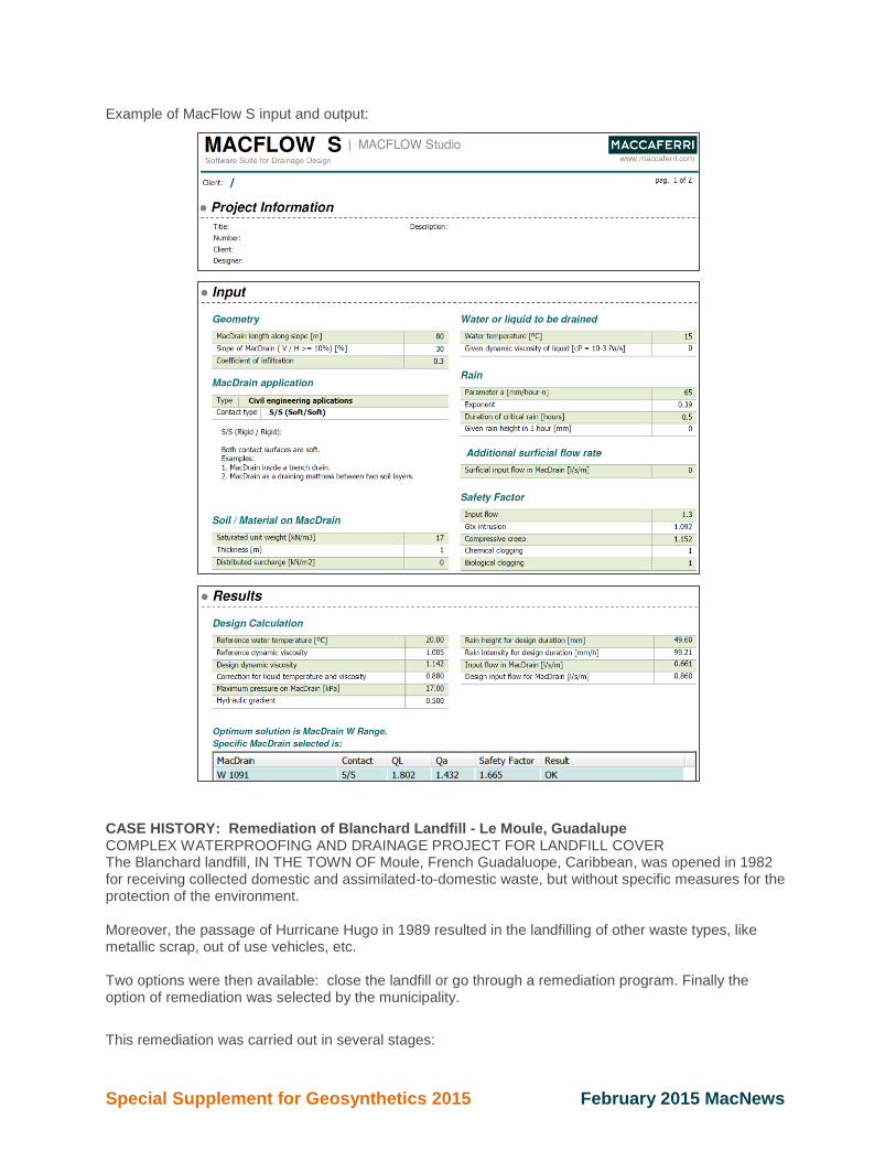
Example of MacFlow S input and output:
CASE HISTORY: Remediation of Blanchard Landfill - Le Moule, Guadalupe COMPLEX WATERPROOFING AND DRAINAGE PROJECT FOR LANDFILL COVER The Blanchard landfill, IN THE TOWN OF Moule, French Guadaluope, Caribbean, was opened in 1982 for receiving collected domestic and assimilated-to-domestic waste, but without specific measures for the protection of the environment. Moreover, the passage of Hurricane Hugo in 1989 resulted in the landfilling of other waste types, like metallic scrap, out of use vehicles, etc. Two options were then available: close the landfill or go through a remediation program. Finally the option of remediation was selected by the municipality.
This remediation was carried out in several stages:
Special Supplement for Geosynthetics 2015 February 2015 MacNews
1. Removal of cars, metallic scraps and all non-domestic wastes to be sent to adequate treatment
processes
2. Re-profiling of the landfill to ensure stability
3. Capping the landfill by: Sealing with a Geocomposite Clay Liner (GCL) to prevent water
penetrating into the waste, percolating to the soil and causing contamination; installation of
geocomposite drains to capture biogas and rain water; and placement of topsoil on the capping to
allow revegetation.
After 6 months of work and nearly 1.5 million € invested, the Blanchard landfill in the town of Moule is now fully rehabilitated. Between July 2012 and January 2013 Contractor CSD Ingenieurs and Project manager RHEA Environnement Antilles completed the works, including: profile remodeling, waterproofing of the capping, biogas management by biofiltration.
The remediation project allowed putting the site in safe conditions and the successful environmental integration of the landfill. Waterproofing was provided by Maccaferri GCL MacLine W11 (10,000 m
2), while drainage was provided
by Maccaferri geocomposite MACDRAIN W1061 (16,000 m2).
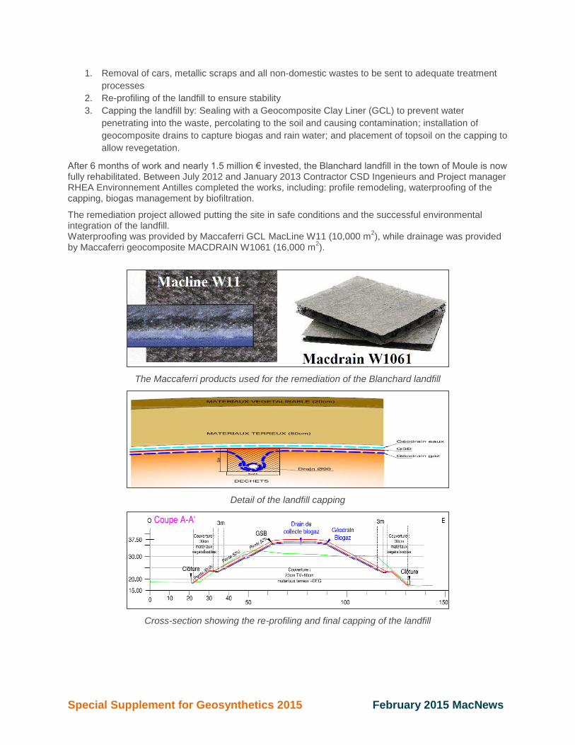
The Maccaferri products used for the remediation of the Blanchard landfill
Detail of the landfill capping
Cross-section showing the re-profiling and final capping of the landfill

Special Supplement for Geosynthetics 2015 February 2015 MacNews
Plan view of the landfill remediation
Installation of MacDrain W1061 geocomposite
Installation of MacLine W11 GCL
The landfill capping near completion
DESIGN OF MACDRAIN W GEOCOMPOSITE FOR RAIN DRAINAGE OF CAPPING. DESIGN BY MACFLOW-S SOFTWARE
Cross-section A-A was selected for the design of the rain water drainage system:
The total slope length is equal to 45 m;
Considering the two berms the average slope length is equal to 1V : 2H, that is the slope angle is
equal to 26°;
Considering that Guadaloupe is in tropical area, the design rainfall intensity is very high: it was
set at 150 mm/hour with a critical duration of 1.0 hour;

Special Supplement for Geosynthetics 2015 February 2015 MacNews
The Reduction Factors for evaluating the available long term flow rate of MacDrain
geocomposites were selected according to the indications provided in the “MacFlow Drainage
Manual” issued by Maccaferri, for the following conditions:
o Surcharge on MacDrain = 1.0 m thick cover soil
o Contacts = Soft / Soft
o Design life = 30 years
Since the drainage system is on slope, MacFlow-S software was used.
Input and output pages from the MacFlow software for the design of Blanchard landfill:
FAQ's: Soil Reinforcement/Geosynthetics
Is the use of a biaxial geogrid economical compared to two uniaxial geogrids installed in cross direction?
It's common assumption that, using one biaxial geogrid is more economical than using two uniaxial geogrids in cross direction. The main reason behind this assumption is the cost of additional layer of geogrid and its installation. This assumption is correct. However, some hidden costs have to be evaluated if biaxial geogrid is chosen and this impacts not only the economical aspect but also the “good Engineering practice”.
To answer this question properly, we have to evaluate two potential scenarios related to different applications. Most importantly, we need to distinguish between “soil stabilization” application and “soil reinforcement” application.
In case of soil stabilization applications, the low strength geogrids (e.g. 30/30, 40/40, --- up to 100/100 kN/m) are used as reinforcement material. The typical applications are road base / sub-base reinforcement and parking area sub-base reinforcement aimed at improving the bearing capacity of the sub-soil by spreading the loads on to much larger surface area.
In case of soil reinforcement applications, the required tensile strength is typically much higher and it is not same in both directions (e.g. Piled embankment, Embankments on voids or on soft soils and similar applications).
In any case, the design tensile strength must be guaranteed in both working directions. This can be achieved by overlapping geogrids. The length of required overlap is based on passive friction and

Special Supplement for Geosynthetics 2015 February 2015 MacNews
bonding. The connection strength at the overlap is calculated using the surcharge load and friction coefficient between soil and geogrid. The length of overlap or the connection strength shall be greater than the required structural strength. Having said that, geogrid strength is governed by the connection strength and the design connection strength is not the strength of geogrid.
The length of geogrid overlap (Le) is calculated using below formula:
𝐿𝑒 ≥ 𝑇𝐷𝑒𝑠𝑖𝑔𝑛 ∗ 𝑓𝑝
𝛾 ∗ ℎ (𝑎′1 tan(𝜑𝑐𝑣1)
𝑓𝑚𝑠+
𝑎′2 tan(𝜑𝑐𝑣2)𝑓𝑚𝑠
)
Where Tdesign Design tensile load in the reinforcement per meter run fp The partial factor for reinforcement pullout resistance γ Unit weight of embankment fill h The average height of embankment fill above the reinforcement length
a'1 The interaction coefficient relating the soil / reinforcement bond angle to tan(𝜑𝑐𝑣1) on one side of the reinforcement a'2 The interaction coefficient relating the soil / reinforcement bond angle to tan(𝜑𝑐𝑣2) on other side of the reinforcement 𝜑𝑐𝑣1 The large stain angle of friction of embankment fill under effective stress condition on one side of the reinforcement 𝜑𝑐𝑣2 The large stain angle of friction of embankment fill under effective stress condition on other side of the reinforcement fms The partial material factor applied to tan(𝜑′𝑐𝑣)
In case of soil stabilization applications, the calculated length of overlap coincides with standard range of overlap (20 to 40cm). It is evident that, in case of soil stabilization the standard geogrid overlap ensures the structural continuity in both main and cross direction because the forces mobilized are very limited and minimum length of overlap is sufficient to fulfill the structural continuity.
The overlap length requirement is completely different when the required design tensile strength is not limited. For example, if we have to provide 50 kN/m of connection strength, the required overlap is 6.6 m with 1.0m of soil cover. The length of overlap is inversely proportional to overburden pressure. As overburden (depth of soil) increases, required overlap length decreases.
Let’s analyze two different design cases:
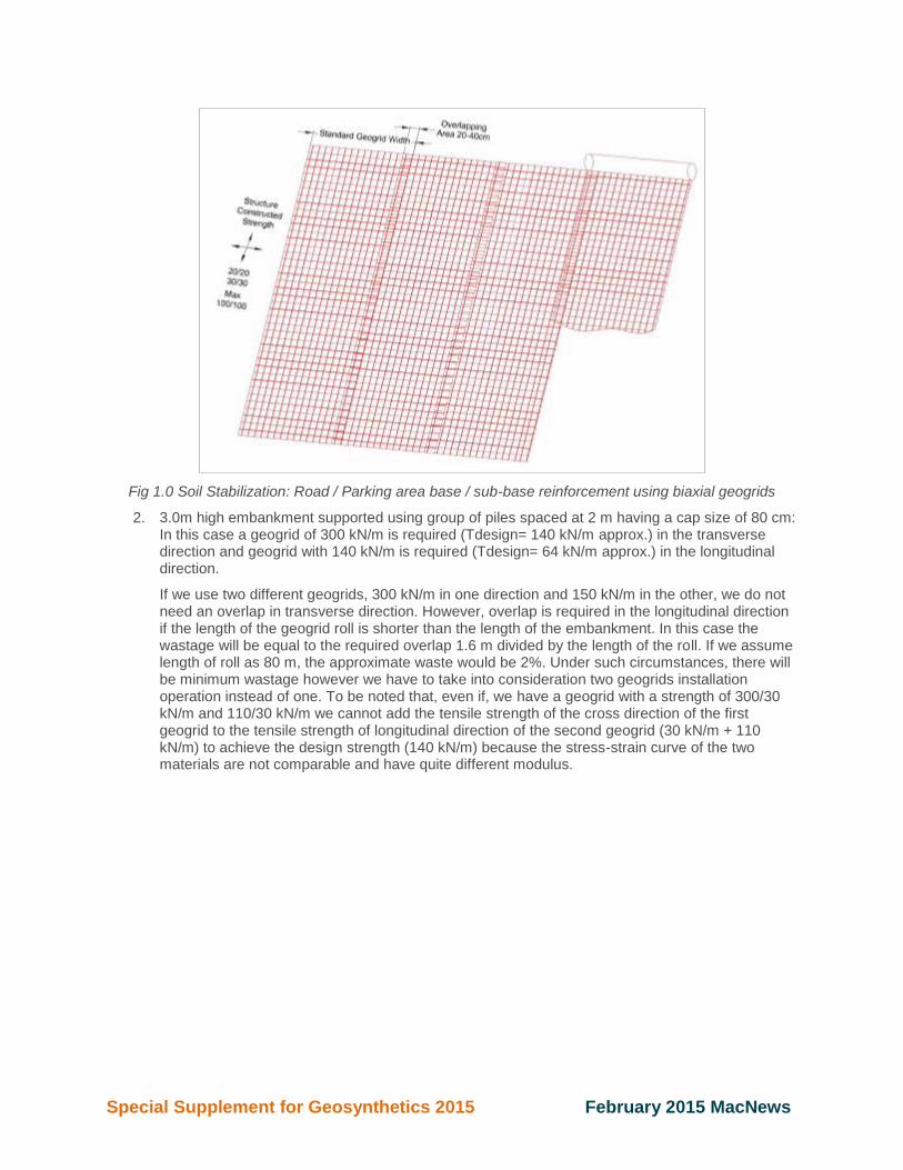
1. Standard road/parking area with 70 cm of base and sub base and 15 cm of asphalt layer; full width approximately 8 meters where a 30/30 kN/m geogrids has to be installed at the base in order to provide a tensile strength of 10 kN/m at 2%. Using above formula to calculate length of geogrid overlap, the required overlap length to guarantee the continuity is 30 cm so the standard overlap length satisfy the requirement; the below sketch shows geogrid installation layout.
Special Supplement for Geosynthetics 2015 February 2015 MacNews
Fig 1.0 Soil Stabilization: Road / Parking area base / sub-base reinforcement using biaxial geogrids
2. 3.0m high embankment supported using group of piles spaced at 2 m having a cap size of 80 cm: In this case a geogrid of 300 kN/m is required (Tdesign= 140 kN/m approx.) in the transverse direction and geogrid with 140 kN/m is required (Tdesign= 64 kN/m approx.) in the longitudinal direction.
If we use two different geogrids, 300 kN/m in one direction and 150 kN/m in the other, we do not need an overlap in transverse direction. However, overlap is required in the longitudinal direction if the length of the geogrid roll is shorter than the length of the embankment. In this case the wastage will be equal to the required overlap 1.6 m divided by the length of the roll. If we assume length of roll as 80 m, the approximate waste would be 2%. Under such circumstances, there will be minimum wastage however we have to take into consideration two geogrids installation operation instead of one. To be noted that, even if, we have a geogrid with a strength of 300/30 kN/m and 110/30 kN/m we cannot add the tensile strength of the cross direction of the first geogrid to the tensile strength of longitudinal direction of the second geogrid (30 kN/m + 110 kN/m) to achieve the design strength (140 kN/m) because the stress-strain curve of the two materials are not comparable and have quite different modulus.
Special Supplement for Geosynthetics 2015 February 2015 MacNews
Fig 2.0 Soil Reinforcement: Piled Embankment Reinforcement using two layers of uniaxial geogrids
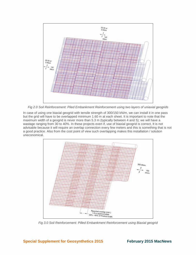
In case of using one biaxial geogrid with tensile strength of 300/150 kN/m, we can install it in one pass but the grid will have to be overlapped minimum 1.60 m at each sheet. It is important to note that the maximum width of a geogrid is never more than 5.3 m (typically between 4 and 5); we will have a wastage ranging from 30 to 40%. In these projects even if, use of biaxial geogrid is correct, It is not advisable because it will require an overlap connection every few meters and this is something that is not a good practice. Also from the cost point of view such overlapping makes this installation / solution uneconomical.
Fig 3.0 Soil Reinforcement: Pilled Embankment Reinforcement using Biaxial geogrid

Special Supplement for Geosynthetics 2015 February 2015 MacNews
From the above examples, in most applications it is not suitable to use biaxial geogrids and it is evident why most of the geogrid manufacturers try to produce materials with limited strength in the cross direction. The knitting or the woven technology has a limitation on minimum numbers of filaments in the “warp” direction. Because of such limitation on number of filaments, cross machine direction strength cannot be lower than 20-30 kN/m. Extruded geogrids or “strip” bonded geogrids does not have such structural limitation so the extruded geogrid are considered fully uniaxial and the strip bonded have a minimum strength of 5 kN/m in the cross machine direction.
To recap, it is evident that to make an appropriate cost comparison, we will have to apply the following formulas keeping in mind good installation practice to analyze which design case is cost effective.
Cost of solution with two geogrids = Cost of geogrid (longitudinal) + Cost of geogrid (transversal) + Cost of longitudinal geogrid installation + Cost of transversal geogrid installation + Cost of geogrid overlapping in longitudinal direction.
Cost of solution with one geogrid = Cost of geogrid + Cost of geogrid installation + Cost of structural overlapping
Upcoming Events: Meet our people and learn about our products and solutions at: Booth #1917 at the SME/CMA, Annual Conference in Denver, CO, Feb. 15-18, 2015 Booth #831 at Geosynthetics 2015 in Portland, OR, Feb. 15-18, 2015 The outdoor section, booth #9024, IFCEE 2015 Conference in San Antonio, TX Mar. 17-21, 2015 60th New Mexico Transportation Engineering Conference in Las Cruces, NM, Apr. 22-24, 2015 New Mexico Floodplain Managers Association, TBD, April 2015 And many more throughout the year!
10303 Governor Lane Blvd. Williamsport, Maryland 21795 800-638-7744 www.maccaferri-usa.com