macroelement modelling of laterally loaded piles and...
TRANSCRIPT
1st International Conference on Natural Hazards & Infrastructure
28-30 June, 2016, Chania, Greece
Macroelement Modelling of Laterally Loaded Piles and Pile-groups
Nikos Gerolymos1
National Technical University of Athens
Orestis Papakyriakopoulos
Technical University of Munich
ABSTRACT
A macro-element model is presented for analysing the response of single piles and pile-groups under lateral loading.
Formulated within the framework of classical elasto-plasticity, the macro-element combines a hardening rule for loading-
unloading-reloading of the Bouc-Wen type coupled with an associative plastic flow rule. The paper aims at determining
two fundamental components of the model, namely the failure surface and the flow rule at post failure response, based
on results from 3D finite element analysis. Comparisons are also given with predictions from upper bound limit
equilibrium solutions based on revisions of Brom’s theory for the lateral capacity of piles
Keywords: Piles, Finite Element Analysis, Macro-element, Constitutive Model
INTRODUCTION
Recent research has shown that the use of laws and equations provided by the theory of elastoplasticity can be
directly applicable to the analysis of foundations in cohesive soil under undrained loading conditions (Martin
and Houlsby, 2000). It has been demonstrated that this approach provides better results in comparison to
Winkler based model, as it is capable of realistically representing the coupling between the various degrees of
freedom. Within the framework of elastoplasticity, the "global" response of the pile-soil system is treated in a
manner similar to that for the "local" response of an infinitesimally small soil element. The stresses and strains
for the soil element are substituted by the generalized forces (in 3-dimensional M-Q-N space) and the
corresponding displacements (θ–u–v) respectively.
In this paper a mathematical framework for macroelement modeling of piles and pile-groups is briefly
presented, emphasizing the nonlinear behaviour of both the soil and the pile. The calibration of the model
parameters is achieved through comparisons with 3D finite element analyses with the use of code PLAXIS.
Given that the ultimate lateral capacity of a pile is directly related to its diameter and bending moment
resistance, which in turn is a function of the axial force imposed (or developed) on the pile, a simple uniaxial
stress-strain model based on the Mohr-Coulomb yield criterion is also developed capable of reproducing the
cross-sectional behaviour of circular reinforced concrete piles in terms of bending moment─curvature
relationship and bending moment─axial force failure envelopes.
1 Corresponding Author: N. Gerolymos, National Technical University of Athens, [email protected]
PHENOMENOLOGICAL MODEL FOR RC PILE SECTION BEHAVIOUR
A Mohr-Coulomb based uniaxial stress-strain constitutive law is developed for modeling the macroscopic
behaviour of a RC circular pile section subjected to a combined bending moment and axial force loading.
Considering force equilibrium at failure in the axial direction, one obtains:
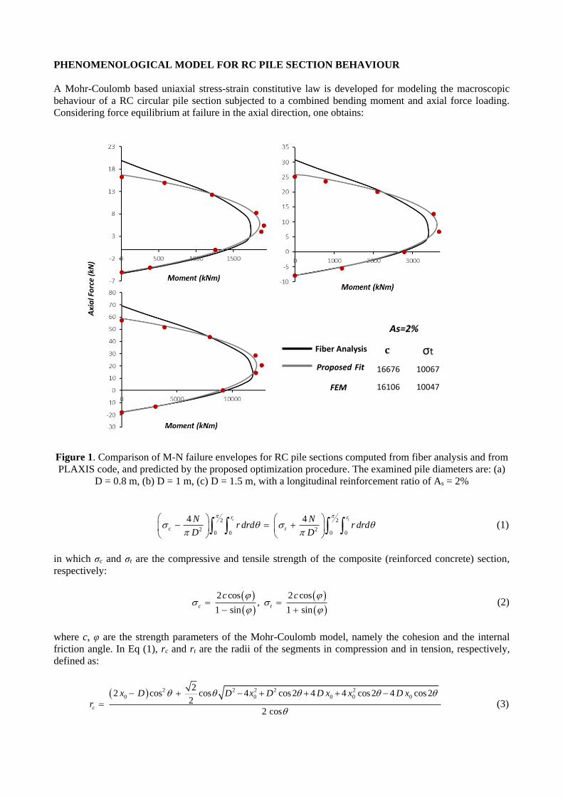
Figure 1. Comparison of M-N failure envelopes for RC pile sections computed from fiber analysis and from
PLAXIS code, and predicted by the proposed optimization procedure. The examined pile diameters are: (a)
D = 0.8 m, (b) D = 1 m, (c) D = 1.5 m, with a longitudinal reinforcement ratio of As = 2%
2 2
2 20 0 0 0
4 4
c tr r
c t
N Nr drd r drd
D D
(1)
in which σc and σt are the compressive and tensile strength of the composite (reinforced concrete) section,
respectively:
2 cos 2 cos,
1 sin 1 sinc t
c c
(2)
where c, φ are the strength parameters of the Mohr-Coulomb model, namely the cohesion and the internal
friction angle. In Eq (1), rc and rt are the radii of the segments in compression and in tension, respectively,
defined as:
2 2 2 2 2
0 0 0 0 0
22 cos cos 4 cos2 4 4 cos2 4 cos2
2
2 cos
c
x D D x D D x x D x
r
(3)
Fiber Analysis
Proposed Fit
FEM
σt
16676 10067
16106 10047
As=2%
Axi
al F
orc
e (k
N)

and rt by substituting x0 in Eq (3) with (D – x0). D is the pile diameter and x0 is the abscissa that defines the
boundary between the zones of the section under compression and tension, respectively. By applying moment
limit equilibrium with respect to the center of the pile section, the following equation is derived:
2 22 2
00 0 0 0 2
c tr r
c t
DM r drd r drd x N
(4)
Figure 2. Comparison of the failure envelopes for a pile in cohesive soil, calculated by PLAXIS and
predicted by the limit equilibrium method, for 4 different factors of safety to vertical loading Fsv. The pile
has a diameter of D = 1 m and a longitudinal reinforcement ratio of As = 1.5 %. Tension (extraction of the
pile) is denoted with negative values
Eqs (1) and (4) form a nonlinear algebraic system. For a given pile diameter and a known combination of
bending moment–axial force at structural failure conditions, there are three unknown variables: c, φ and x0 .
The aforementioned system is solved with the use of a genetic algorithm–based optimization procedure,
implemented in MATLAB. The performed optimization targets to a best fit on a predefined M–N failure
envelope by minimizing the root mean squared error (RMSE) of the bending moment at failure (the fitness
function):
2
,
1
1( )
n
i T i
i
RMSE M M Mn
(5)
Shear Force (kN)
Shear Force (kN)
Mo
men
t (k
Nm
) Fsv =
2
5
20
-2 (tension)

in which Mi is the bending moment computed by Eq (4), MT,i is the target bending moment, and n, the number
of MT.i – Ni pairs that define the failure envelope. It is interesting to observe that the proposed simplified Mohr-
Coulomb−based constitutive model can be easily reduced to a Tresca with tension cut-off−based one, by
equating the compressive strength in Eq (2) with σc = 2c and setting the tensile strength equal to the tension
cut-off. Fig 1 shows the M-N failure envelopes for a pile cross-section with a longitudinal reinforcement ratio
of As = 2 % and for three different diameters (D = 0.8 m, 1 m and 1.5 m). Comparison is given between the
predictions of: (a) the proposed optimization procedure, (b) the 3D FE analysis with PLAXIS, and (c) the fiber
analysis with the computer code USC-RC (Esmaeily 2001).
Figure 3. Finite element verification of the associative plastic flow rule for a wide range of load
combinations. Observe that the depth to the plastic hinge hp increases for increasing negative load angles [M
/ Q = ω, ω* = (Qy / My) ω] reaching a maximum value at the vertex of the failure envelope (at approximately
ω = -50o). For load angles greater than |ω| > 50o , the plastic hinge moves violently from its deepest location
to the head of the pile.
FINITE ELEMENT ANALYSIS
Single Pile
A 16 m long pile with a diameter of 1 m is analyzed. Both the pile and the soil are modeled with 10-node
tetrahedral elements. The plan view dimensions of the finite element model is 1.3L x 1.3L in width with a
depth of 1.5 L (where L is the length of the pile), carefully weighting the effect of the boundaries on the
response of the pile and the computational time. Zero-displacement boundary conditions prevent the out of
hp (m)
ω (deg)Normality
hp , Fsv = 1.25
upl/φpl , Fsv = inf
hp , Fsv = inf
Q / Qy
M / My
ω Q / Qy
M / My
ω
hp
Μ
QN
plane deformation at the vertical sides of the model, while the base is fixed in all three directions. Special
interface elements were placed between the pile and the soil, thus allowing slippage and gapping to occur.
For the total stress analysis under undrained conditions, soil behaviour is described by the Mohr-Coulomb
model with Su = 50 kPa, and specific weight of γ = 18 kΝ/m3, elasticity modulus of Es = 25000 kPa and
Poisson’s ratio of v = 0.45. Based on the macroscopic constitutive law for reinforced concrete circular pile
sections, the behaviour of the pile was modelled via a Mohr-Coulomb failure criterion with c = 15262 kPa, φ
= 0ο, tension cut-off σt = 7534 kPa and Elasticity modulus E = 30 GPa, corresponding to a longitudinal
reinforcement ratio of As = 1.5 %.
Fig 2 compares the failure envelopes in moment—shear force space as for 4 different factors of safety against
vertical loading, as it is predicted by an upper bound limit equilibrium solution based on Brom’s theory (1964)
for the lateral capacity of piles and calculated by the FE models. The hypothesis of plastic flow rule for the
incremental displacement to rotation ratio at the pile head is verified in Fig 3.
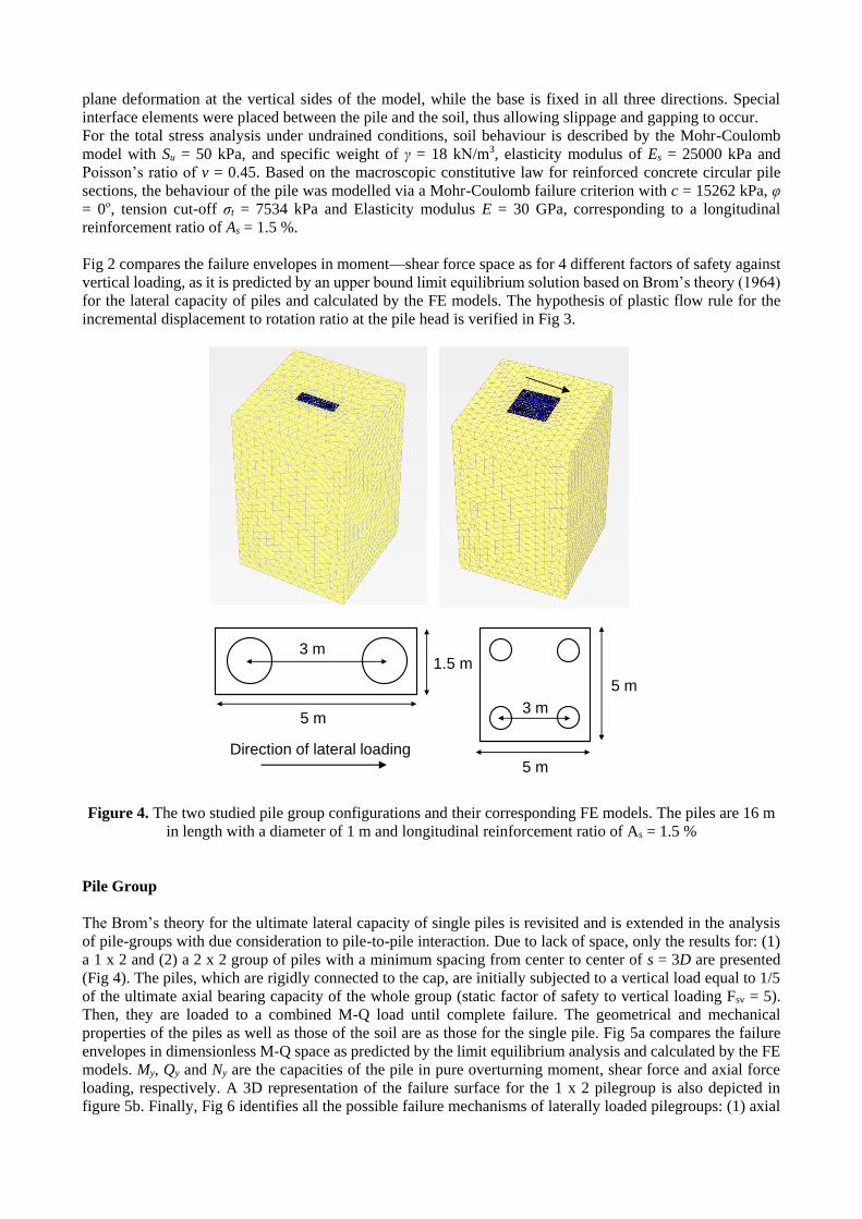
Figure 4. The two studied pile group configurations and their corresponding FE models. The piles are 16 m
in length with a diameter of 1 m and longitudinal reinforcement ratio of As = 1.5 %
Pile Group
The Brom’s theory for the ultimate lateral capacity of single piles is revisited and is extended in the analysis
of pile-groups with due consideration to pile-to-pile interaction. Due to lack of space, only the results for: (1)
a 1 x 2 and (2) a 2 x 2 group of piles with a minimum spacing from center to center of s = 3D are presented
(Fig 4). The piles, which are rigidly connected to the cap, are initially subjected to a vertical load equal to 1/5
of the ultimate axial bearing capacity of the whole group (static factor of safety to vertical loading Fsv = 5).
Then, they are loaded to a combined M-Q load until complete failure. The geometrical and mechanical
properties of the piles as well as those of the soil are as those for the single pile. Fig 5a compares the failure
envelopes in dimensionless M-Q space as predicted by the limit equilibrium analysis and calculated by the FE
models. My, Qy and Ny are the capacities of the pile in pure overturning moment, shear force and axial force
loading, respectively. A 3D representation of the failure surface for the 1 x 2 pilegroup is also depicted in
figure 5b. Finally, Fig 6 identifies all the possible failure mechanisms of laterally loaded pilegroups: (1) axial
5 m
3 m
3 m
5 m
5 m
1.5 m
Direction of lateral loading

bearing capacity failure accompanied with in-depth plastic hinges, (2) plastic hinges at the connection with the
cap and at a certain depth, (3) axial bearing capacity failure in conjunction with pile-to-cap plastic hinges.
Figure 5. (a) Comparison of the failure envelopes for a pile in cohesive soil calculated by PLAXIS and
predicted by the limit equilibrium method for a factor of safety to vertical loading Fsv = 5, and (b) 3D
representation (in M-Q-N space) of the failure surface for the 1x2 pilegroup. The pile has a diameter od D =
1 m and a longitudinal reinforcement ratio of As = 1.5 %.
Figure 6. Identification of failure mechanisms for laterally loaded pilegroups (analysis with PLAXIS). Three
areas are distinguished each corresponding to a specific failure mode: Mode 1: Axial bearing capacity failure
with in-depth plastic hinges, Mode 2 Plastic hinges at the connection with the cap and at a certain depth, Mode
3: Axial bearing capacity failure with pile-to-cap plastic hinges.
MACROELEMENT MODELING
The model is formulated in the framework of classical elastoplasticity, and combines features of: (a) the
bounding surface plasticity, (b) the critical state concept, and (c) a hardening evolution law and unloading-
N/Ny*
-30000
-20000
-10000
0
10000
20000
30000
0 1000 2000 3000 4000 5000 6000 7000 8000
M (kNm)
Q (kN)
Pile-group: 1 x 2
Pile-group: 2 x 2
(a) (b)
M / My
Q / Qy
1
2
3
1 2 3
reloading rule of the modified Bouc-Wen type. According to this formulation the tangent elastoplastic stiffness
matrix that relates the incremental force vector to the incremental displacement vector, is given in the following
matrix form:
1
1 2
ep e T e T e
g f g f
ΤΚ Χ Κ I Φ Φ Κ Φ Φ Κ Η Η Χ (6)
in which Ke is the elastic stiffness matrix of the piles with due consideration to pile-to-pile interaction (in the
elastic regime), Φf and Φg account for the failure surface and plastic flow rule, respectively, and H1 and H2
control the hardening law and unloading-reloading rule. The terms in matrices H1 and H2 are functions of the
dimensionless hardening parameter ζ, which is of the Bouc-Wen type (Bouc 1971, Wen 1976, Gerolymos and
Gazetas, 2005; Gerolymos et al. 2009, Drosos et al. 2012; Tasiopoulou and Gerolymos 2010). Finally, X is the
geometric transformation matrix that accounts for the kinematic constraints that the pile-cap (in the case of
pile-groups) imposes on the piles.
CONCLUSION
A macroelement model was presented for analysing the response of piles and pile-groups under lateral loading.
Two of the most fundamental components of the proposed macroelement, the failure envelope and the flow
rule at post-failure (or at failure) conditions, are determined by exploiting the results from a comprehensive
3D finite element analysis with code PLAXIS. The macroscopic, in terms of bending moment—curvature
relation, nonlinear response of pile under combined axial-moment loading was described by an appropriately
calibrated Mohr-Coulomb—based stress-strain model. The results from the numerical analysis compare well
with those from a limit equilibrium solution and verify the hypothesis of associativity of the plastic flow rule.
REFERENCES
Bouc R. Modele mathematique d’ hysteresis. Acustica. 1971, 24(1): 16-25 (in French) Broms, B. 1964. Lateral resistance of piles in cohesive soils. Journal of Soil Mechanics and Foundation Division, ASCE,
90(3): 27-63.
Drosos V., Gerolymos N., Gazetas G. Constitutive Model for Soil Amplification of Ground Shaking: Parameter
Calibration, Comparisons, Validation. Soil Dynamics and Earthquake Engineering.2012, 42: 255-274. Gerolymos N. and Gazetas G. 2005. Phenomenological model applied to inelastic response of soil–pile interaction
systems. Soils and Foundations, 45(4): 119-132. Gerolymos N., Drosos V., Gazetas G. Seismic Response of Single-Column Bent on Pile: Evidence of Beneficial Role of
Pile and Soil Inelasticity. Bulletin of Earthquake Engineering. 2009, 7(2): 547-573. Esmaeily A. 2001. USC-RC. Software for analyzing behavior of a single reinforced concrete member. Version 1.0.2,
USC Civil Engineering Department. Beaty M, Byrne P. UBCSAND constitutive model, Version 904aR. Documentation Report: UBCSAND constitutive
model on Itasca UDM Web Site, 2011, pp. 69. Martin, C. M., Houlsby, G. T. 2000. Combined loading of spudcan foundations on clay: laboratory tests, Geotechnique,
50(4): 325-338. Tasiopoulou P., Gerolymos N. Constitutive Modeling of Sand: Formulation of a New Plasticity Approach”, Soil
Dynamics and Earthquake Engineering. 2016, 82: 205-221.
Wen Y.K. Method for random vibration of hysteretic systems. J. Engng Mech., ASCE. 1976, 102(2): 249-263.