made in usa - morrison and marvinmorrisonandmarvin.com/files/mill_vise.pdf · material size b box...
TRANSCRIPT

4:1
DESCRIPTION
MATERIAL SHEET
MORRISON & MARVIN ENGINE WORKS
B
Dave Otto
SCALE
DESIGNED BY
1/7/2018
REV
Roland Morrison / Marvin Hedberg
DRAWN BY
Box 555 Benton City, WA 99320 USA
SIZE
DATE Vise Assembly
Made in USA
Download a full set of drawings from MorrisonandMarvin.com
1 of 18 1

14
6
7
18
2
10
1
8
16
11
13
12
5
15
Mill Vise Exploded
17
3
Made in USA
Download a full set of drawings from MorrisonandMarvin.com
9
1.25:1 2 of 18 1
1/7/2018
Box 555 Benton City, WA 99320 USA
Dave Otto
REV
Roland Morrison / Marvin Hedberg
DRAWN BY
DESCRIPTION
DATE
SIZEMATERIAL SHEETSCALE
MORRISON & MARVIN ENGINE WORKS
DESIGNED BY
B
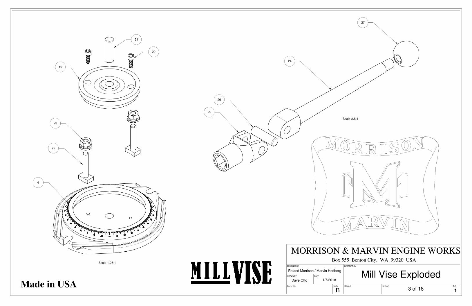
Scale 1.25:1
23
22
4
20
21
19
Scale 2.5:1
24
27
26
25
Dave Otto
DESCRIPTION
REV
DATE
Roland Morrison / Marvin Hedberg
SCALE
DESIGNED BY
MATERIAL
1/7/2018
Box 555 Benton City, WA 99320 USA
SIZE
DRAWN BY
SHEET
B
MORRISON & MARVIN ENGINE WORKS
Mill Vise ExplodedMade in USA
3 of 18 1
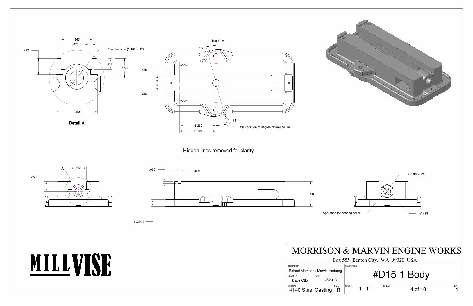
.250( )
.893
.065 .094
.282
.282
1.262
15 °
15 °
1.309
Top View
2X Location of degree reference line
n.250Ream
n.438Spot face for bearing collar
.563
.350
A
n.406Counter bore x.20.292
.750
.563
.200
.075
.350
Detail A
SCALE
DESIGNED BY
MORRISON & MARVIN ENGINE WORKS
1/7/2018
Roland Morrison / Marvin Hedberg
Dave Otto
DRAWN BY DATE
SIZEMATERIAL
B
Box 555 Benton City, WA 99320 USA DESCRIPTION
SHEET REV
1 : 14140 Steel Casting
Hidden lines removed for clarity
4 of 18
#D15-1 Body
1
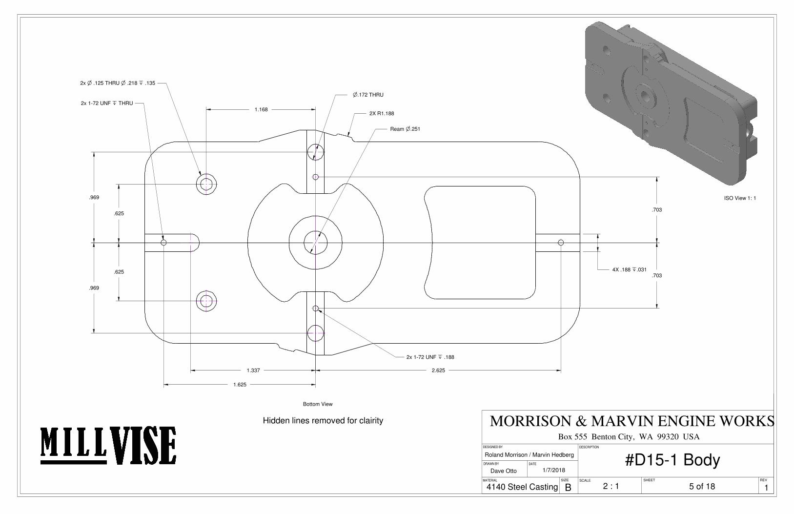
.1884X x.031
n.251Ream
1.337
1.625
2.625
R1.1882X
.625
.625
.969
.969
n.172 THRU
.703
.703
1.1682x 1-72 UNF x THRU
2x 1-72 UNF x .188
2x n .125 THRU n .218 x .135
Bottom View
Hidden lines removed for clairity
ISO View 1: 1
1/7/2018
DESIGNED BY
Roland Morrison / Marvin Hedberg
REV
MORRISON & MARVIN ENGINE WORKS
SHEET
DATEDRAWN BY
Box 555 Benton City, WA 99320 USA
Dave Otto
SIZEMATERIAL
B
DESCRIPTION
SCALE
4140 Steel Casting 2 : 1 5 of 18
#D15-1 Body
1

.094
.125
.063
.351( )
.371( )
A
A B
B
A
2.313
1.475
.313 x.008 .500
.313
.749
.625
.625
1.500
.094 x.008
.094 x.008
.561
2x 5-40 UNC x .313
Cut Line
Break sharp corner with fileapproximately .03 radius
.561
.561
.371( )
Jaws inverted to show detail
R.313 On CL
.806
.008
.418
.570
Section A-A
.120
90 °
.236 On CL
.570
Section B-B
Detail A
File or machine square cornerto blend with casting taper
SCALE
DESCRIPTION
MORRISON & MARVIN ENGINE WORKS
DATE
Roland Morrison / Marvin Hedberg
Dave Otto 1/7/2018
SHEETSIZE
BMATERIAL REV
Box 555 Benton City, WA 99320 USA
DRAWN BY
DESIGNED BY
4140 Steel Casting 2:1
#D15-2 & #D15-6 Jaw Casting
6 of 18 1
Refer to machining notes;1: All interior cast surfaces need to remain square and parallel to outside edges.2: To insure proper location of nut approximately .06 of material needs to be removed from the bottom surface of the casting, when machining bottom features. Failure to do this may also cause the top surface to break though into the cavity when the top is brought to proper thickness.
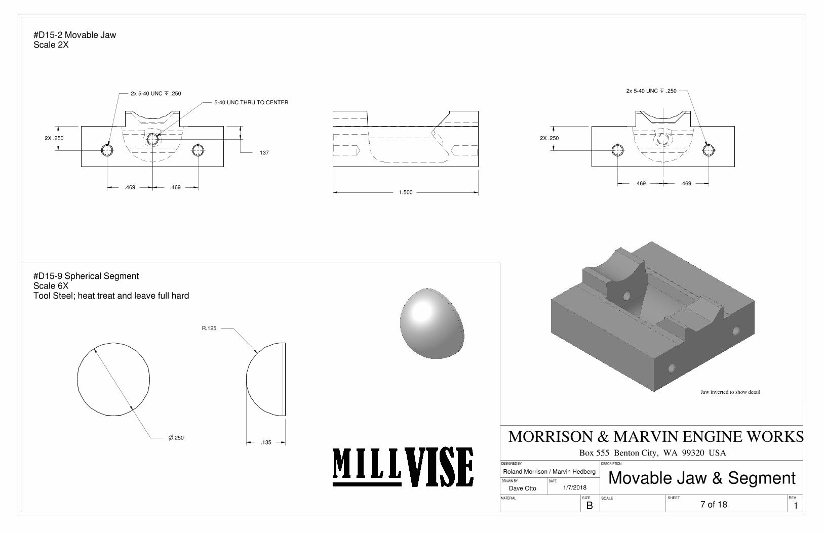
1.500
.2502X
.469 .469
2x 5-40 UNC x .250
.469 .469
.2502X
.137
5-40 UNC THRU TO CENTER
2x 5-40 UNC x .250
Jaw inverted to show detail
n.250
R.125
.135
REV
1/7/2018
MORRISON & MARVIN ENGINE WORKS
DESIGNED BY
SCALE
Roland Morrison / Marvin Hedberg
DATE
DESCRIPTION
MATERIAL
DRAWN BY
SIZE
B
Dave Otto
SHEET
Box 555 Benton City, WA 99320 USA
Movable Jaw & Segment
#D15-2 Movable JawScale 2X
7 of 18
#D15-9 Spherical SegmentScale 6XTool Steel; heat treat and leave full hard
1

.250
.469 .469
2x 5-40 UNC x THRU
#D15-6 Stationary Jaw
3:14140 Steel Casting 8 of 18
Jaw inverted to show detail
1
.282
.500
DESIGNED BY
SCALE
DESCRIPTION
1/7/2018
B
DRAWN BY
Box 555 Benton City, WA 99320 USA
DATE
Roland Morrison / Marvin Hedberg
MATERIAL
MORRISON & MARVIN ENGINE WORKS
Dave Otto
SHEETSIZE REV
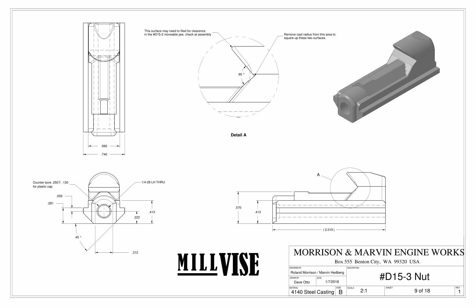
.281
45 °
.413
.312
.222
.059
1/4-28 LH THRUCounter bore .250x .130
for plastic cap
.740
.560
.413
.570
2.015( )
A
90 °
Detail A
Remove cast radius from this area to square up these two surfaces.
This surface may need to filed for clearence in the #D15-2 moveable jaw, check at assembly
Dave Otto
DESCRIPTION
DRAWN BY
REVMATERIAL
Box 555 Benton City, WA 99320 USA DESIGNED BY
DATE
Roland Morrison / Marvin Hedberg
SIZE SHEET
1/7/2018
SCALE
B
MORRISON & MARVIN ENGINE WORKS
4140 Steel Casting
#D15-3 Nut
2:1 9 of 18 1
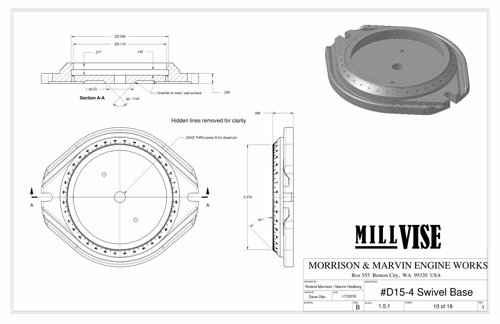
A A
Hidden lines removed for clarity
.250n THRU press fit for dowel pin
.466
2.375
45 °
n2.206
.125
.63( n)
90 °TYP
.277
.230
n2.115
Section A-A
Chamfer to meet cast surface
DESCRIPTION
Box 555 Benton City, WA 99320 USA
Roland Morrison / Marvin Hedberg
Dave Otto 1/7/2018
DATE
MATERIAL SHEET
DRAWN BY
SCALE
DESIGNED BY
SIZE
MORRISON & MARVIN ENGINE WORKS
REV
B
#D15-4 Swivel Base1.5:1 10 of 18 1
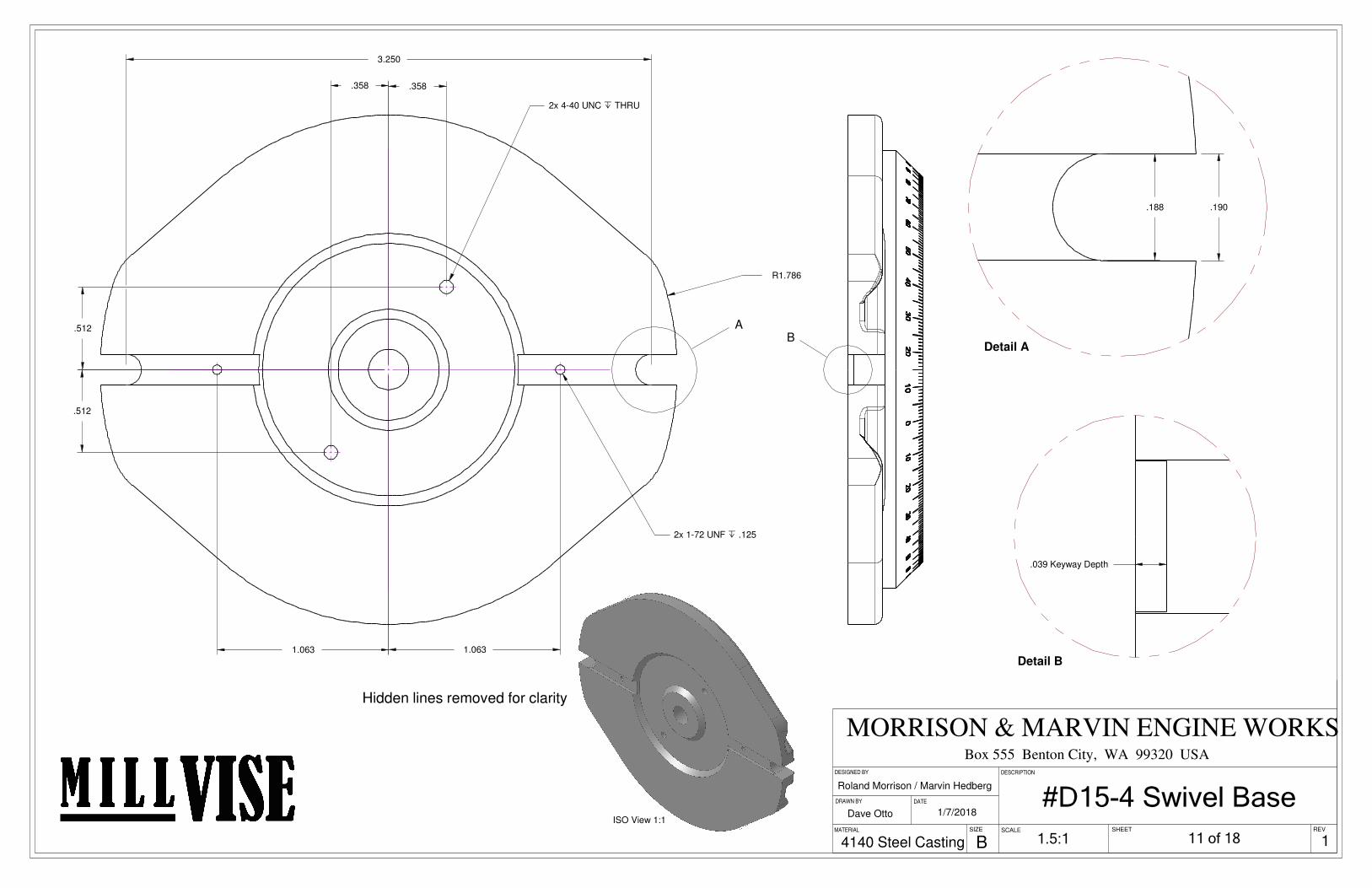
R1.786
1.063 1.063
.358 .358
.512
.512
3.250
A
2x 1-72 UNF x .125
2x 4-40 UNC x THRU
ISO View 1:1
.188 .190
Detail AB
.039 Keyway Depth
Detail B
DESCRIPTION
BREV
DATE
SCALE
Box 555 Benton City, WA 99320 USA
MATERIAL
DRAWN BY
1/7/2018
SIZE
DESIGNED BY
Roland Morrison / Marvin Hedberg
MORRISON & MARVIN ENGINE WORKS
SHEET
Dave Otto
4140 Steel Casting 1.5:1
#D15-4 Swivel Base
11 of 18
Hidden lines removed for clarity
1

15 °
15 °
4140 Cast Steel
ISO view 1:1
1/7/2018
SCALE SHEET
Roland Morrison / Marvin Hedberg
DESCRIPTION
B
MORRISON & MARVIN ENGINE WORKS
SIZE
DESIGNED BY
Box 555 Benton City, WA 99320 USA
REV
Dave Otto
DRAWN BY DATE
MATERIAL
#D15-4 Swivel Base
3:1 12 of 18 1
Engrave as shown: 10 degree lines .09 long 1 degree lines .04 long Numbers may be stamped with .06 letter stamps, or engraved .04 letter height. Use previously machined keyways on bottom for alignment.
.160
.125
n1.666
n1.765
n.500
1.250
n.250
2x n.113 x THRU
vn.187 x .135
A A
ISO Scale 1:1
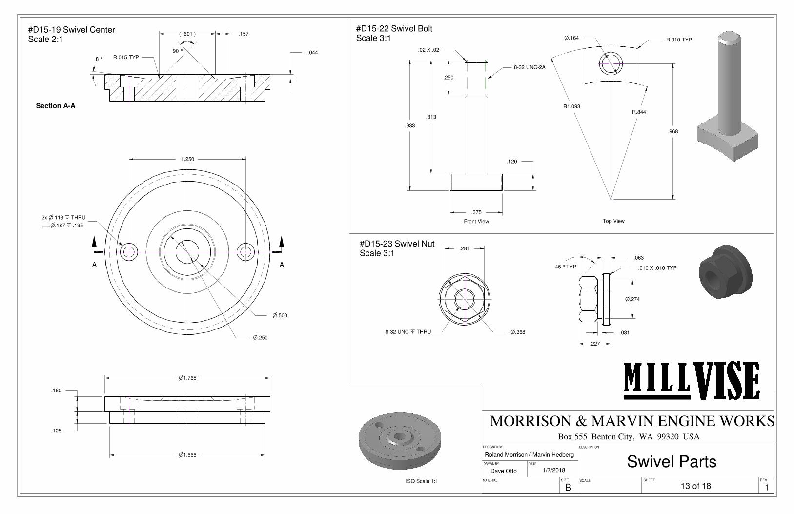
.044R.015 TYP8 °
90 °
.157.601( )
Section A-A
.250
.813
.933
.120
.375
.02 X .02
Front View
8-32 UNC-2A
R.844R1.093
.968
R.010 TYPn.164
Top View
n.368
.281
8-32 UNC x THRU
.227
45 °TYP
.031
n.274
.063
.010 X .010 TYP
Roland Morrison / Marvin Hedberg
DESIGNED BY
MORRISON & MARVIN ENGINE WORKSBox 555 Benton City, WA 99320 USA
SCALE
DESCRIPTION
BREV
DRAWN BY
MATERIAL
DATE
SIZE
1/7/2018Dave Otto
SHEET
Swivel Parts
#D15-19 Swivel CenterScale 2:1
#D15-22 Swivel BoltScale 3:1
#D15-23 Swivel NutScale 3:1
13 of 18 1
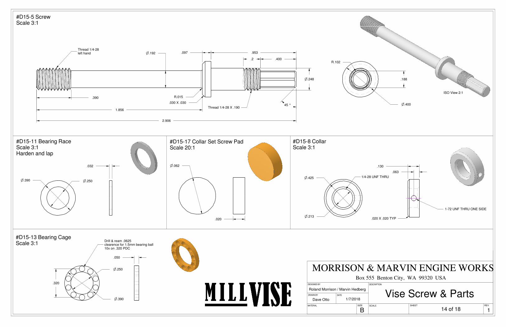
2.906
.097
1.856
.390
n.192
n.248
.953
.400
R.015
.030 X .03045 °
.2
Thread 1/4-28 left hand
Thread 1/4-28 X .190n.400
.188
R.102
ISO View 2:1
n.390 n.250
.032
n.390
n.250
.320
Drill & ream .0625clearence for 1.5mm bearing ball10x on .320 PDC
.050
n.425
n.213
1/4-28 UNF THRU
.130
.063
.020 X .020 TYP
1-72 UNF THRU ONE SIDE
n.062
.020
DESIGNED BY
Roland Morrison / Marvin Hedberg
REV
DESCRIPTION
Dave Otto
MORRISON & MARVIN ENGINE WORKS
DRAWN BY
SHEET
Box 555 Benton City, WA 99320 USA
1/7/2018
SIZE SCALE
B
DATE
MATERIAL
Vise Screw & Parts
14 of 18
#D15-5 ScrewScale 3:1
#D15-8 CollarScale 3:1
#D15-17 Collar Set Screw PadScale 20:1
#D15-11 Bearing RaceScale 3:1Harden and lap
#D15-13 Bearing CageScale 3:1
1
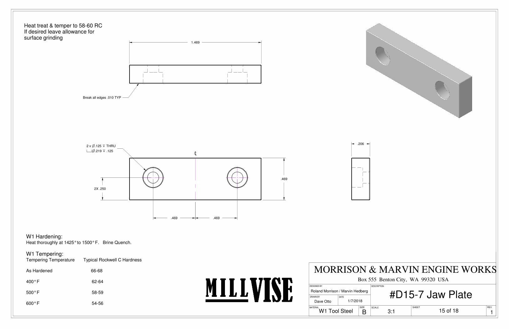
.469
.2502X
.469 .469
q2 x n.125 x THRU
vn.219 x .125
1.469
Break all edges .010 TYP
.206
SIZE
DRAWN BY
SHEETSCALE
1/7/2018
Roland Morrison / Marvin Hedberg
Dave Otto
DATE
MATERIAL REV
MORRISON & MARVIN ENGINE WORKSBox 555 Benton City, WA 99320 USA
DESIGNED BY DESCRIPTION
B
#D15-7 Jaw Plate
3:1 15 of 18
Heat treat & temper to 58-60 RCIf desired leave allowance for surface grinding
1W1 Tool Steel
W1 Hardening:Heat thoroughly at 1425° to 1500° F. Brine Quench.
W1 Tempering:Tempering Temperature Typical Rockwell C Hardness
As Hardened 66-68
400° F 62-64
500° F 58-59
600° F 54-56

63 °
.313
.251
.279
.020 X .020
n.126Ream
n.313
.313
20 °
R.125
R.141n.1247Ream
.188
30 °
2 °
.281
.281
6-32 UNC-2A
n.138
.215 n
1.781
.250
n.156
6-32 UNC x .250
.171
R.228
.315
3/16 Hex broach through
MATERIAL
DESIGNED BY
SHEET
DATE
B
Roland Morrison / Marvin Hedberg
MORRISON & MARVIN ENGINE WORKS
DRAWN BY
SIZE REV
Box 555 Benton City, WA 99320 USA
Dave Otto
DESCRIPTION
1/7/2018
SCALE
#D15-24 HandleScale 3X
#D15-25 YokeScale 3X
Handle Parts
16 of 18 1
#D15-27 BallScale 3X

.460 .5361.367 2.293
.18754X
.438
.438
.800
.800
.341
.341
R.2182X
15 °2X
.4382X
R.060 TYP
n.250 x THRU
2x 8-32 UNC THRU
2.750
.469
.031
5.000
SHEET
DESCRIPTION
DATE
SIZE
DRAWN BY
Dave Otto
MATERIAL REV
MORRISON & MARVIN ENGINE WORKSBox 555 Benton City, WA 99320 USA
BSCALE
1/7/2018
Roland Morrison / Marvin Hedberg
DESIGNED BY
17 of 181:1Cast AluminumTooling Plate
Body Machining Fixture
1

Item Number Quantity Part Number Part Name Material Sheet Number
1 1 D15-1 Body 4140 4-5
2 1 D15-2 Movable Jaw 4140 6 & 7
3 1 D15-3 Nut 4140 9
4 1 D15-4 Swivel Base 4140 10-12
5 1 D15-5 Screw 1144 14
6 1 D15-6 Stationary Jaw 4140 6 & 8
7 2 D15-7 Jaw Plate W1 15
8 1 D15-8 Collar 12L14 14
9 1 D15-9 Spherical Segment 01 7
10 1 D15-10 Dog Point Set Screw Alloy Steel
11 2 D15-11 Bearing Race 01 14
12 10 D15-12 Bearing Ball Alloy Steel
13 1 D15-13 Bearing Cage Brass 14
14 1 D15-14 Plastic Cap Nylon
15 2 D15-15 Stationary Jaw Screw Alloy Steel
16 1 D15-16 Collar Set Screw Alloy Steel
17 1 D15-17 Collar Set Screw Pad Brass 14
18 4 D15-18 Jaw Plate Screw Alloy Steel
19 1 D15-19 Swivel Center 12L14 13
20 2 D15-20 Swivel Center Screw Alloy Steel
21 1 D15-21 Swivel Pin Alloy Steel
22 2 D15-22 Swivel Bolt 12L14 13
23 2 D15-23 Swivel Nut 12L14 13
24 1 D15-24 D15-24 Handle 12L14 16
25 1 D15-25 D15-25 Handle Yoke 12L14 16
26 1 D15-26 D15-26 Handle Pin Alloy Steel
27 1 D15-27 D15-27 Handle Ball Aluminum 16
28 1 Body Machining Fixture Aluminum 17
SHEETSIZE
Dave Otto
DESIGNED BY
SCALE
Roland Morrison / Marvin Hedberg
B
Box 555 Benton City, WA 99320 USA
REV
DATE
MATERIAL
DRAWN BY
MORRISON & MARVIN ENGINE WORKS
DESCRIPTION
1/7/2018
Download a full set of drawings from MorrisonandMarvin.com
Mill Vise BOM
18 of 18 1