madison parks division
TRANSCRIPT

Madison Parks Division 210 Martin Luther King, Jr. Blvd., Room 104
Madison, WI 53703 608-266-4711 ● cityofmadison.com/parks
November 28, 2017
NOTICE OF ADDENDUM
ADDENDUM 1
CONTRACT NO.8062 Revise and amend the contract document(s) for the above project as stated in this addendum, otherwise, the original document shall remain in effect. General
1. The geotechnical exploration report for the project has been amended to include a short discussion about potential installation challenges of helical piers on page 7 of the amended report. Other deep foundation types, such as micropiles, are permissible. Driven piles will not be acceptable due to noise issues.
Specifications
2. SECTION 102.9 BIDDER’S UNDERSTANDING Omit: SECTION 102.9 BIDDER’S UNDERSTANDING
Add: SECTION 102.9 BIDDER’S UNDERSTANDING In the preparation of Drawings and Specifications, Strand Associates, Inc.® relied upon the following reports of explorations and tests of subsurface conditions at the Site which are attached at the end of the SPECIAL PROVISIONS: Report dated November 17, 2017, prepared by CGC, Inc., of Madison, Wisconsin, titled: Geotechnical Exploration Report–Proposed Bridge Replacements Vilas Park Island, Madison, Wisconsin, consisting of 23 pages. The technical data in the above report, upon which Contractor may rely, consists of boring methods, level of subsurface water, boring logs, laboratory test methods and results, and boring locations all as of the date made. City accepts no responsibility for accuracy of the soil data or water level information. Soil borings and report, included with these Contract Documents, were not obtained for the purposes of designing excavations and trenches. Soils information was used by Strand Associates, Inc.® for design purposes of new structures only. Contractor shall assure itself by personal examination as to subsurface conditions and shall provide its own investigations and make its own assumptions to comply with OSHA and any other applicable laws and regulations regarding excavation and trenching requirements.

2
3. SECTION 105.12 COOPERATION BY CONTRACTOR, last paragraph.
Add: ‘Swallow and other migratory birds’ nests have been observed on or under the existing bridge. All active nests (when eggs or young are present) of migratory birds are protected under the federal Migratory Bird Treaty Act. The nesting season for swallows and other birds is usually between May 1 and August 30. The Contractor shall either prevent active nests from becoming established, or apply for a depredation permit from the US Fish and Wildlife Service for work that may disturb or destroy active nests. The need for a permit may be avoided by removing the existing bridge structure prior to nest occupation by birds, or clearing nests from all structures before the nests become active in early spring. As a last resort, the Contractor shall prevent birds from nesting by installing a suitable netting device on the remaining structure prior to nesting activity. The cost for preventing nesting and/or permitting shall be incidental to Bid Items 90005 and 90006 Removing Old Structure Over Waterway.’
4. BID ITEM 90008 – HELICAL PILES, DELIVERED AND INSTALLED Omit: BID ITEM 90008 – HELICAL PILES, DELIVERED AND INSTALLED Add: BID ITEM 90008-DEEP FOUNDATIONS – DESIGNED, DELIVERED AND INSTALLED. Per attached.
5. Contract 8062 Attachment A – Geotechnical Exploration Report. Omit: Contract 8062 Attachment A – Geotechnical Exploration Report, dated March 7, 2017. Add: Contract 8062 Attachment A – Geotechnical Exploration Report - REVISED, dated November 27, 2017. Per attached.
Plans
6. All Sheets. Replace: At all locations on the drawings where the word ‘helical’ appears, replace it with ‘deep foundation’.
7. Sheet 15. Omit: full sheet. Add: Sheet 15, revision dated 11-27-17. Per attached.
Bid Tab
8. BID ITEM 90008 – HELICAL PILES, DELIVERED AND INSTALLED Omit: Bid item. Add: BID ITEM 90008-DEEP FOUNDATIONS – DESIGNED, DELIVERED AND INSTALLED.


Page 1 of 8
BID ITEM 90008–DEEP FOUNDATIONS–DESIGNED, DELIVERED AND INSTALLED A. Description. The work consists of designing, delivering and installing deep foundation supports for the bridge abutments. The specific type(s) of deep foundations used shall be determined by the contractor based on site conditions and the foundation loads shown on the drawings. Acceptable deep foundation types include, but are not limited to, helical piles and micropiles. The type of deep foundation used shall be suitable for the site conditions. The deep foundation system shall be designed for a minimum service life of 75 years. B.1 Materials. If a deep foundation type other than micropiles or helical piles is used, materials used shall be determined by the deep foundation designer. B.1.A Micropiles. Micropile materials shall be designed by the deep foundation designer. B.1.B Helical Piles. Helical piles shall be by Foundation Supportworks, Inc., 12330 Cary Circle, Omaha, NE 68128, or equal. Manufacturer of helical piles shall have at least five years of production experience manufacturing helical piles and have documentation that manufacturer’s helical piles have been used successfully in at least five engineered construction projects within the last three years. Helical piles subject to compression loading shall be hollow round shaft. Helical piles subject to tension loading shall be solid square or round shaft or hollow round shaft. Size of piles shall be determined by the designer/manufacturer based on the specific project conditions. Pile shaft sections shall be in full, direct contact within couplings so as to remove coupling bolts and coupling welds from the “in-service” axial load path. Pile shafts and couplings shall have a fit-up tolerance of 1/16-inch or less. Helix plates shall meet the following geometry and spacing criteria to minimize soil disturbance:
1. True helix-shaped plates that are normal to the shaft such that the leading and trailing edges are within 1/4-inch of parallel.
2. Helix pitch is 3 inches (+ 1/4-inch). 3. All helix plates have the same pitch. 4. Helix plates have circular edge geometry. 5. Helix spacing along the shaft shall be between 2.4 and 3.6 times the helix diameter. 6. Helix plates are arranged along the shaft such that they all theoretically track the
same path as the proceeding plate. Central steel shaft of the lead and extension sections shall be a hollow steel structural section meeting ASTM A500 Grade B or C. Shaft coupling shall be factory welded to the extension shaft and be a hollow steel structural section meeting ASTM A513 Type 5. Helix plates shall be factory welded to the lead or extension shaft sections and shall be structural steel plate material meeting ASTM A572 Grade 50. Brackets shall be structural steel plate material meeting ASTM A572 Grade 50 or ASTM A36. All steel components shall receive a hot-dipped galvanized finish system in accordance with ASTM A123 after fabrication.

Page 2 of 8
All hardware shall conform to ASTM A325 and shall be hot-dipped galvanized in accordance with ASTM A153. B.2 Design and Performance Requirements. Deep foundations shall be designed to support the compressive or tensile load(s) as shown on the drawings. B.2.A Micropiles. The design shall include pile design and pile-footing connection design. The design shall conform with applicable provisions of accepted industry practice. B.2.B Helical Piles. The overall length, helix configuration and minimum torsional resistance of a helical pile shall be such that the required capacity is developed by the helix plate(s) in an appropriate bearing stratum. All structural steel pile components shall be designed within the limits provided by the American Institute of Steel Construction (AISC) Specification for Structural Steel Buildings (AISC-360) using Allowable Stress Design (ASD) method of analysis. Product testing in accordance with ICC-ES Acceptance Criteria 358 may also be considered as an acceptable means of establishing system capacities. Except where noted otherwise on the drawings, all piles shall be installed to provide an ultimate torque-correlated capacity based on an ASD analysis using a minimum factor of safety of 2.5 applied to the service or nominal loading. The required ultimate torque-correlated capacity shall be verified at each pile location by monitoring and recording the final installation torque and applying default torque correlations per ICC-ES AC358. Except where noted otherwise on the drawings, all tension anchors shall be installed to provide a minimum factor of safety against ultimate pullout resistance of 3, a maximum axial deflection at nominal tension load of 0.5 inches, and must satisfy the deflection criteria as stated on the plans or drawings. Pre-tensioning anchors is an acceptable and common means of reducing deflection at service loads. The pile design shall take into account group efficiency from pile spacing, pile buckling potential, soil stratification, and strain compatibility issues. B.3 Qualifications of Installing Contractor and Designer. The installing contractor and pile designer shall submit to the City the following documentation prior to starting work. Work shall not begin until all the submittals have been received and approved by the City. All costs associated with incomplete or unacceptable submittals shall be the responsibility of the Contractor. Evidence of installing contractor’s competence in the installation of proposed deep foundations shall be provided to the City’s satisfaction and shall include the following:
1. If helical piles are used, pile manufacturer’s certificate of competency for the installation of helical piles.
2. A list of at least three projects completed within the previous three years wherein
the installing contractor installed proposed deep foundations similar in size and

Page 3 of 8
scope to this project. Such list to include names and phone numbers of those project representatives who can verify the installing contractor’s participation in those projects.
Evidence of deep foundation designer’s competence shall be provided to the City’s satisfaction and shall include the following:
1. Registration as a Professional Engineer in the State of Wisconsin. 2. If helical piles are used, recommendation from the pile manufacturer or
manufacturer’s representative. B.4 Submittals. At a minimum, submit the following for review by City prior to installation:
1. Qualifications of deep foundation installer and designer. 2. Design calculations stamped by a professional engineer licensed in the State of
Wisconsin. 3. Design drawings stamped by a professional engineer licensed in the State of
Wisconsin. B.4.A Micropiles. Submit qualifications, design calculations, design drawings, and product information for proposed deep foundation system. B.4.B Helical Piles. Submit the following helical pile design documents for review by City prior to installation:
1. Certification from the pile designer that the proposed piles meet the requirements
of this specification. 2. Qualifications of the manufacturer, installing contractor and pile designer per
Sections B.1 and B.3. 3. Design calculations stamped by a professional engineer licensed in the State of
Wisconsin. 4. Product designations for helical lead and extension sections and all ancillary
products to be supplied at each helical pile location. 5. Individual pile nominal loads, factors of safety, and required ultimate torque
correlated capacities, where applicable. 6. Individual pile loading requirements (if any). 7. Manufacturer’s published allowable system capacities for the proposed pile
assemblies, including load transfer devices.

Page 4 of 8
8. Calculated mechanical and theoretical geotechnical capacities of the proposed piles.
9. Minimum pile termination torque requirements. 10. Maximum estimated installation torque and allowable installation torque rating of
the proposed piles. 11. Minimum and/or maximum embedment lengths or other site-specific embedment
depth requirements as may be appropriate for the site soil profiles. 12. Inclination angle and location tolerance requirements. 13. Copies of certified calibration reports for torque measuring equipment to be used
on the project. The calibrations shall have been performed within one year of the proposed helical pile installation starting date or as recommended by the equipment manufacturer.
C.1 Construction Methods. Deep foundations shall be installed in accordance with deep foundation designer requirements. C.1.A Micropiles. A record shall be kept of each pile and shall include as a minimum: 1. Length of pile installed. 2. Depth to rock. 3. Length of rock socket. 4. Theoretical grout volume. 5. Actual grout volume for primary and regrouting. 6. Conditions encountered during drilling. 7. Date and time of installation. 8. Pile number or location description. C.1.B Helical Piles. Helical piles shall be installed in the locations indicated on the drawings and in accordance with the manufacturer’s instructions. Helical piles shall be installed within 3 inches of the indicated drawing location. Helical pile shaft alignment shall be within 2 degrees of the inclination angle shown on the drawings. Depth of piles shall be sufficient to obtain the required working loads in compression, as determined by installation torque readings. Cut off tops of piles and anchor to new foundations with brackets. Top elevation of the helical piles shall be within 2 inches of the design vertical elevation. C.2 Helical Pile Installation. Installing contractor shall give City minimum 24-hour notice prior to start of pile installation. The helical pile installation technique shall be such that it is

Page 5 of 8
consistent with the geotechnical, logistical, environmental, and load carrying conditions of the project. The lead section shall be positioned at the appropriate site survey stake location as determined from the drawings. The helical pile sections shall be advanced into the soil in a continuous manner at a rate of rotation less than 25 revolutions per minute (rpm). Sufficient crowd shall be applied to advance the helical pile sections at a rate approximately equal to the pitch of the helix plate per revolution. The rate of rotation and magnitude of down pressure shall be adjusted for different soil conditions and depths. The magnitude of down pressure shall exceed the amount of torque required to install the pile. Extension sections shall be provided to obtain the required minimum overall length and minimum torsional resistance required. C.3 Helical Pile Termination Criteria. The minimum final torsional resistance and any required pile length and embedment depth criteria, as specified by the helical pile designer, must be satisfied prior to terminating the pile installation. In the event any helical pile fails to meet these production quality control termination criteria, the following remedies may be suitable, if authorized by the City:
1. If the installation fails to meet the minimum torsional resistance criterion at the minimum embedment length as determined by the pile designer: a. Continue the installation to greater depths until the torsional resistance
criterion is met, provided that, if a maximum length constraint is applicable, continued installation does not exceed said maximum length constraint, or
b. Demonstrate acceptable pile performance through pile load or proof testing, or
c. Replace the pile with one having a different helix plate configuration. The replacement pile must not exceed any applicable maximum embedment length criteria and be embedded to a length that places the last helix plate at least equal to its own diameter beyond the depth of the first helix plate of the replaced pile and meet the minimum torsional resistance criterion or pass load or proof testing.
2. If the torsional resistance during installation reaches the helical pile’s allowable
torque rating prior to satisfaction of the minimum embedment length criterion: a. Terminate the installation at the depth obtained if approved by City, or b. Replace the pile with one having a shaft with a higher torsional strength
rating. The replacement pile must be installed to satisfy the minimum embedment length criterion. It must also be embedded to a length that places the last helix plate at least equal to its own diameter beyond the depth of the first helix plate of the replaced pile without exceeding any applicable maximum embedment length requirements and it must meet the minimum final torsional resistance criterion, or
c. Replace the pile with one having a different helix plate configuration. The replacement pile must be installed to satisfy the minimum embedment length criterion. It must also be embedded to a length that places the last helix plate at least equal to its own diameter beyond the depth of the first helix plate of the replaced pile without exceeding any applicable maximum embedment length requirements, and it must meet the minimum final torsional resistance criterion.
3. If the installation reaches a specified maximum embedment length, as determined

Page 6 of 8
by the pile designer, without achieving the minimum torsional resistance criterion: a. If approved by City, remove and reinstall the pile at a position at least three
times the diameter of the largest helix plate away from the initial location. Original embedment length and torsional resistance criteria must be met. The pile repositioning may require the installation of additional helical piles with nominal loads adjusted for these spacing changes, or
b. Demonstrate acceptable pile performance through pile load testing, or c. De-rate the load capacity of the helical pile based on default or site-specific
torque correlation factors and install additional piles as necessary. 4. Replace the pile with one having a different helix plate configuration. The
replacement pile must be installed to satisfy the minimum and/or maximum embedment length criterion and it must meet the minimum final torsional resistance criterion.
5. If a helical anchor fails to meet acceptance criteria in a performance or proof test:
a. Install the anchor to a greater depth and installation torque and re-test provided that, if a maximum embedment length constraint is applicable, continued installation will not exceed said maximum length constraint, or
b. Replace the anchor with one having more and/or larger helix plates. It must be embedded to a length that places its last helix at least three times its own diameter beyond the position of the first helix of the replaced pile without exceeding any applicable maximum embedment length requirements. This replacement pile must be re-tested, or
c. If approved by the City, de-rate the load capacity of the helical anchor and install additional anchors. Additional anchors must be installed at positions that are at least three times the diameter of the largest helix away from any other anchor locations and are approved by the City. Anchors installed in cohesive soils shall not be spaced closer than four helix diameters.
6. If a helical pile fails a production quality control criterion as described in this
Section or for any reason other than described in this Section, any proposed remedy must be approved by the City prior to initiating its implementation at the project site.
Submit copies of individual helical pile installation records within 24 hours after each installation is completed. Formal copies shall be submitted within 30 days following the completion of the helical pile installation. These installation records shall include the following information:
1. Date and time of installation. 2. Location of helical pile and pile identification number. 3. Installed helical pile model and configuration. 4. Termination depth, pile head depth, and length of installed pile. 5. Actual inclination of the pile.
Page 7 of 8
6. Final torsional resistance. 7. Calculated working load capacity based on final torsional resistance. 8. Comments pertaining to interruptions, obstructions, or other relevant information.
C.3 Helical Pile Field Compression Load Testing. If field compression load testing is done, the installing contractor shall furnish all labor, equipment and pre-production helical piles necessary to accomplish the testing as shown in the approved pile design documentation. Installing Contractor shall apply the specified loads for the specified durations and record the specified data, for the specified number of piles. No deviations from the test plan(s) will be allowed without explicit approval in writing from the City. Pile testing shall be in general accordance with the ASTM D1143 quick test method and the following criteria:
1. Failure criteria shall be in accordance with AC358 and is when plunging occurs or
when the net deflection exceeds 10% of the average helix plate diameter, whichever occurs first.
2. An alignment load equal to 5% of the anticipated failure load or maximum
anticipated test load may be applied prior to the start of the test to take out slack in the load test frame.
3. Loading increments shall be performed at 5% of the anticipated failure load or
maximum anticipated test load with a minimum hold time of 4 minutes at each increment.
4. Upon completion of the maximum test load hold increment, the pile shall be
unloaded in 5 to 10 even increments with minimum hold times of 4 minutes at each increment.
Installing contractor shall provide the City copies of raw field test data within 24 hours after the completion of each load test. Formal test reports shall be submitted within 30 days following test completion. Formal test reports shall include the following information:
1. Name of project and Installing Contractor’s representative(s) present during load testing.
2. Name of manufacturer’s representative(s) present during load testing, if any. 3. Name of third party test agency and personnel present during load testing, if any. 4. Date, time, duration and type of the load test. 5. Unique test identifier and map showing the test pile location. 6. Pile model and installation information including shaft type, helix configuration,
lead and extension section quantities and lengths, final pile tip depth, installation

Page 8 of 8
date, total test pile length and final termination torque. 7. Calibration records for applicable pile installation and test equipment. 8. Tabulated test results including cumulative pile head movement, loading
increments and hold times. 9. Plots showing load versus deflection for each loading/unloading interval.
C.4 Helical Pile Field Pre-Tensioning for Tension Anchors. The installing contractor shall furnish all labor, equipment and materials necessary to accomplish the pre-tensioning as shown in the approved anchor design documentation. Installing contractor shall apply the specified loads for the specified durations and record the specified data, for the specified number of anchors. Anchor testing shall be in general accordance with ASTM D3689. Limit the maximum test load to 1.33 times the design load. Installing contractor shall provide the City copies of raw field test data or reports within 24 hours after completion of each tension anchor pre-tension. Formal test reports shall be submitted within 30 days following completion of anchors. Formal test reports shall include the following information:
1. Name of project and installing contractor. 2. Name of Installing Contractor’s supervisor during installation. 3. Type of test. 4. Date, time, and duration of test. 5. Unique identifier and location of helical anchor test. 6. Description of calibrated testing equipment and test set-up. 7. Actual helical anchor type and configuration. 8. Steps and duration of each load increment. 9. Cumulative anchor-head movement at each load step.
D. Method of Measurement. The City will measure the Deep Foundations-Designed, Delivered, and Installed bid item by a single lump sum unit. E. Basis of Payment. The bid item will be paid for at the contract unit price. Payment is full compensation for designing, fabricating, delivering, and installing a complete deep foundation system as specified. Payment includes compression load testing of compression anchors, as needed; and for pre-tensioning of tension anchors. Changes or modifications to foundation type during construction, as required to satisfy the specification requirements, are the responsibility of the contractor.

November 27, 2017
C17051-4
Mr. Michael Sturm
City of Madison – Parks Division
210 Martin Luther King, Jr. Boulevard, Room 104
Madison, WI 53703
Re: Geotechnical Exploration Report - REVISED
Proposed Bridge Replacements
Vilas Park Island
Madison, Wisconsin
Dear Mr. Sturm:
Construction Geotechnical Consultants, Inc. (CGC) is providing a revised geotechnical report for
the proposed replacement bridge project described above to update the helical pier foundation
recommendations. Other parts of the report are not changed. The purpose of this exploration
program was to evaluate the subsurface conditions within the proposed construction area and to
provide geotechnical recommendations regarding bridge foundation design and construction. An
electronic copy of the revised report is being sent to you and Keith Behrend at Strand Associates, and
we can provide a paper copy upon request.
PROJECT AND SITE DESCRIPTIONS
We understand that two existing timber-framed pedestrian bridges which connect the Vilas Park
Island to the surrounding park areas will be replaced. The timber-pile supported bridges, which have
an average clear width of 7.5 ft, are located on the north and south sides of the island in the shallow
Vilas Park lagoon. The current bridge spans are approximately 73 ft and 100 ft at the north and south
bridges, respectively. It is our understanding that the replacement bridges will be constructed at the
same general locations and utilize existing approach paths and retaining walls. The new structures
will be pile supported and have cast-in-place concrete decks with clear widths of 12 ft. In order to
maintain site aesthetics and minimize site disturbance to the park, it is our understanding that existing
timber piles may potentially remain in-place. However, the existing timber piles, which support the
abutments, will need to be evaluated and depending on their condition, may need to be supplemented
with new piles installed adjacent to the existing timber piles. Alternatively, the existing timber piles
may need to be replaced with new steel driven piles constructed following removal of the existing
abutments.
Attachment A

Mr. Michael Sturm
City of Madison – Parks Division
November 27, 2017
Page 2
S:\DOC\Nov 2017\17051-4.geo.ajb_das.docx
Although the bridges will generally experience lighter loads associated with pedestrian and bicycle
traffic, occasional maintenance vehicles and infrequent emergency vehicles may also travel on the
bridges. It is our understanding that the load capacity of the new bridges has not been determined,
and that the City of Madison is considering designs which accommodate two alternative maximum
loading criteria: 1. All City maintenance vehicles, with a maximum load of 50,000 lbs (e.g., tandem-
axle dump truck), and 2. All maintenance vehicles excluding the tandem-axle dump truck, with a
maximum load of 28,000 lbs (e.g., clam truck).
SUBSURFACE CONDITIONS
Subsurface conditions in the vicinity of the proposed bridge abutments were explored by drilling four
Standard Penetration Test (SPT) borings to depths of 24 to 39 ft below existing site grades. Note that
the borings were originally planned to extend to depths of 50 to 100 ft, but were stopped short after
extending the borings at least 10 to 25 ft into dense to very dense, apparent sandstone bedrock, which
has also been encountered in borings completed at Henry Vilas Zoo. The borings were drilled by
Badger State Drilling (under subcontract to CGC) on February 13 and 14, 2017 using an ATV-
mounted D-50 drill-rig equipped with hollow-stem augers and an automatic SPT hammer. The
boring locations and planned depths were selected by CGC in consultation with the City, and were
located in the field by CGC based off a map provided by the City. Ground surface elevations at the
boring locations were estimated by CGC using an online mapping tool (DCiMap) and should be
considered approximate (± 1 ft). The boring locations are shown in plan on the Soil Boring Location
Exhibit attached in Appendix A.
The subsurface profile encountered at the boring locations was fairly similar and can be described by
the following strata, in descending order:
6 to 12 in. of topsoil/topsoil fill; over
About 3 to 8 ft of very loose to loose silt, with the upper 3 to 5 ft being described as
organic silt in each of the borings; underlain by
About 5 to 8 ft of clayey soils, including medium stiff to stiff lean clay and medium
dense clayey sand; followed by
About 5 ft of loose to medium dense sand with significant silt content in Borings 1
and 2; over
Apparent dense to very dense weathered to increasingly competent sandstone
bedrock.
Groundwater was noted at depths of 3.5 to 6 ft below existing grades, which corresponds to
approximately EL 843 to 845 ft, during drilling. As a reference, it is our understanding the normal

Mr. Michael Sturm
City of Madison – Parks Division
November 27, 2017
Page 3
S:\DOC\Nov 2017\17051-4.geo.ajb_das.docx
controlled surface water elevation of nearby Lake Wingra is approximately 847.7 ft. Groundwater
levels can be expected to fluctuate with seasonal variations in precipitation, infiltration,
evapotranspiration, the water level in Lake Wingra, as well as other factors. A more detailed
description of the site soil and groundwater conditions is presented on the Soil Boring Logs attached
in Appendix B.
DISCUSSION AND RECOMMENDATIONS
As mentioned above, in order to minimize site disturbance and to maintain site aesthetics, it is our
understanding that the quality and structural integrity of the existing timber piles will be evaluated
prior to design of the new bridges. Depending on the quality of the existing timber piles, and the
capacity required for the new structures, the existing timber piles may remain in-place and be
supplemented by new driven piles at each abutment. If the quality of the timber piles are not suitable
for re-use, new abutments also supported by driven piles will be constructed.
Subject to the limitations discussed below and based on the subsurface exploration, it is our opinion
that the proposed bridges can be supported by either: 1) The existing abutments (pending timber pile
evaluation by others indicate satisfactory condition and capacity) supplemented with steel HP pile or
helical piers installed through the shallow soft/loose soils to bear within the apparent sandstone
bedrock underlying the site; or 2) New HP pile or helical piers supporting abutments constructed
following removal of the existing abutments. Note that if the condition and capacity of the existing
timber piles are determined to be satisfactory such that the existing abutments may remain and be
supplemented with additional new piles constructed adjacent to the existing abutments, helical piers
may prove the more feasible foundation support alternative because smaller installation equipment
would likely reduce site disturbance and lower anticipated mobilization costs compared to driven
piles. Note that CGC did not complete an analysis of the existing timber piles. We recommend that
the structural integrity of the existing timber piles and abutments be reviewed/evaluated by a
licensed structural engineer during the design phase of this project.
The following subsections provide our recommendations for design/construction or driven pile and
helical pier bridge foundation support alternatives. The revised report includes some additional
considerations regarding the use of helical pier foundations. Additional information regarding the
conclusions and recommendations presented in this report are discussed in Appendix C,
1. Foundation Recommendation Alternatives
A. Driven Piles
In our opinion, steel HP-section piles (WisDOT Standard Specifications, Section 550) will likely be
the preferred driven pile type for this project where piles will be driven into bedrock, and these piles
are expected to encounter driving refusal (and the required driving resistance) within the very dense
weathered sandstone bedrock layer. The top of the bedrock layer was observed at approximately 12
to 22 ft below existing site grades in the borings, with very dense conditions typically encountered

Mr. Michael Sturm
City of Madison – Parks Division
November 27, 2017
Page 4
S:\DOC\Nov 2017\17051-4.geo.ajb_das.docx
below 25 ft in Borings 1 and 2 (north), with slightly shallower very dense conditions observed in
Borings 3 and 4 (south), at between about 15 and 20 ft. HP piles driven to practical refusal are
expected to drive approximately 5 to 10 ft into the very dense bedrock. Therefore, the estimated
depth for HP10X42 piles to develop a maximum ultimate driving resistance of 180 tons is about 30
to 35 ft below existing grades (approximately EL 814 to 819 ft) in Borings 1 and 2, and 20 to 25 ft
below existing grade (approximately EL 825 to 830 ft) in Borings 3 and 4. If a higher capacity is
required, HP12X53 are anticipated to drive to similar depths as HP10X42 piles, but have a higher
maximum driving resistance of 220 tons due to the larger pile section.
The driving criteria for production piling should be established by the modified Gates formula, as
discussed in the WisDOT Bridge Manual, Chapter 11. Using the modified Gates Formula, HP10x42
piles driven to a resistance of 180 tons will have a factored axial compression resistance of 90 tons,
assuming a resistance factor (dyn) of 0.5 (see Section 11.3.1.18.2). Similarly, HP12x53 piles driven
to a maximum driving resistance of 220 tons will have a factored axial compression resistance of 110
tons. If dynamic or static pile load testing is completed, the resistance factor can be increased
(effectively increasing the available load carrying capacity of the piles), but because the piles will be
driven to refusal within the sandstone bedrock layer, we do not anticipate that the moderate to
significant expense associated with pile load testing will make economic sense for this project. It
may also be the case that the bridge loads are light enough such that the maximum load per pile
allowed by WisDOT may not be required for this project, as has been the case for other recreational
path bridges in Madison. In which case, the actual required driving resistance should be sated on the
plans. We can provide additional consultation on load testing, if needed.
Based on our past experience completing drivability analyses and within piles driven to refusal
within weathered bedrock, HP10X42 piles can generally be driven to refusal (or the required driving
resistance) with an appropriately sized pile hammer without overstressing the piles. However, we
recommend that a drivability analysis be completed by the pile driving contractor prior to
construction to check that the selected pile type, cushion and hammer are compatible and do not
result in the pile being overstressed. We recommend including rock tips on the ends of the HP piles
to reduce the potential for damage to piles driven into bedrock: rock tips also assist in the piles
driving straighter.
Other pertinent pile design parameters include the following:
For adequate frost protection, we recommend that the abutment pile caps be founded
at least 4 ft below finish grade. A minimum embedment depth of 2.5 ft is
recommended for sill abutments, per WisDOT Bridge Manual.
It is recommended that the minimum spacing between individual piles be no less
than 2.5 ft or 2.5 times the pile diameter, whichever is greater. WisDOT
recommends a maximum pile spacing of 8 ft. During driving, heaving and/or lateral
displacements of driven piles may occur during subsequent nearby pile driving
Mr. Michael Sturm
City of Madison – Parks Division
November 27, 2017
Page 5
S:\DOC\Nov 2017\17051-4.geo.ajb_das.docx
operations. Therefore, it is important that horizontal and vertical alignment checks
be performed during pile driving operations. Piles that heave more than 0.25 in.
vertically must be reseated. However, heaving is generally not a concern with HP
piling since they are considered non-displacement piles.
To minimize pile driving problems, new embankment fill material in the vicinity of
the abutments or wing walls should not contain cobbles or boulders.
Appropriate scour protection should be provided to prevent soil eroding from the
below the abutments (and around the piles) in the event of high water events.
B. Helical Piers
Depending on the maximum loading of the new structures, as well as the quality of the existing
timber piles at each structure, helical piers may be a more feasible alternative to provide
supplemental bridge abutment support. Helical piers are a proprietary product that involves the
design and installation of a deep foundation system which transfers loads through upper loose or soft
soil zones to bear within more suitable bearing strata. At this site, helical piers can be designed to
extend through the existing organic and softer clay soils to bear within the underlying very dense
weathered sandstone bedrock, using the soil parameters summarized in Table 1. Helical piers can
often be installed using lightweight, mobile equipment (e.g., skidsteer or mini-excavator with special
attachments) and are often used in applications where there is limited space available, similar to this
site. In addition, because the mobilization cost will likely be much lower than for driven piles (which
generally require a crawler crane), helical piers may prove to be the more economical foundation
support alternative.
Helical pier capacity will vary depending on the number and size of helices, depth of installation and
bearing stratum. Using the computer program HeliCAP V2.0 (produced by Chance/Hubbell) we
estimated the capacity of a two-helix (8 in./10 in.) helical pier installed to different depths at the two
bridge locations. In general, we estimate that ultimate helical pier capacities (in compression) ranging
from about 20 to 60 kips (potentially higher with heavy-duty helical piers) can be developed for
helical piers installed to depths of 15 to 30 ft below existing site grades, within the higher end in the
range of ultimate capacities developed within deeper, very dense sandstone bedrock. Based on the
very dense nature of the sandstone bedrock, smaller diameter helix configurations (e.g., 8 and 10 in.)
may be required to allow for the pier to penetrate into the strata to achieve required capacity.
However, it should be noted that within deeper, more competent sandstone bedrock layers, the helical
pier capacity at higher loads will likely be limited by the structural capacity of the helices and not
from the geotechnical capacity of the soils/bedrock. The helical pier depths and capacities should be
considered approximate and since helical piers are proprietary (with a multitude of variables), the
helical pier installer should determine the helix configuration and depth necessary to satisfy project
requirements.


Mr. Michael Sturm
City of Madison – Parks Division
November 27, 2017
Page 6
S:\DOC\Nov 2017\17051-4.geo.ajb_das.docx
The torque of the equipment installing the helical piers is generally correlated with axial capacity,
although static load tests can also be completed to confirm the ultimate and allowable capacities. A
minimum factor of safety of 2.0 to 2.5 is generally used for helical pier design. If a factor of safety
of 2.0 is used to determine the allowable helical pier capacity, we recommend that one static load test
be performed per bridge location to confirm the helical pier design satisfies the project requirements.
The static load tests should be performed on piers installed to similar installation depths and torques
as production piers. Additionally, the torque of each pier should be monitored during installation to
document that each pier is torqued to the minimum torque established by the static load tests or
empirical correlations to ultimate capacity. If static load tests are not performed, we recommend
using a minimum factor of safety of at least 2.5 in determining the allowable capacity, and the
installation torque of each pier should be monitored, which is empirically correlated to the ultimate
capacity. Since there are multiple proprietary helical pier systems, it is the responsibility of the
contractor to determine that their selected helical pier configuration, installation procedures and
termination criteria satisfy the project requirements.
Other helical pier considerations include the following (the last two bullet points form the basis of
the revised report):
The helical pier installer should have provisions to deal with the presence of potential
obstructions. If obstructions are encountered, removing obstructions with an
excavator would be one method to deal with the obstructions. Using smaller diameter
helix configuration may also assist in the installation process but may require deeper
piers to develop capacity.
The shallow organic and softer clay soils have relatively low lateral capacity. As
such, round helical pier shafts, which have higher resistance to buckling, are
recommended over square shafts. A buckling analysis should be completed to check
that the pier shaft has adequate buckling resistance.
The shallow organic soils may be slightly corrosive to steel, which may result in
section loss over time. Therefore, we recommend either increasing the steel section of
the shaft to accommodate potential section loss or covering the upper part of the shaft
with an anti-corrosion coating to reduce the corrosion potential.
If the existing timber piles are supplemented with helical piers (or driven piles),
consideration should be given to the compatibility of the two different foundation
system. Loads will tend to be attracted to the stiffer foundation elements, which may
result in localized higher stresses in an abutment of mixed foundation elements. We
recommend that that the structural integrity of the existing piles be
reviewed/evaluated by a licensed structural engineer.
Mr. Michael Sturm
City of Madison – Parks Division
November 27, 2017
Page 7
S:\DOC\Nov 2017\17051-4.geo.ajb_das.docx
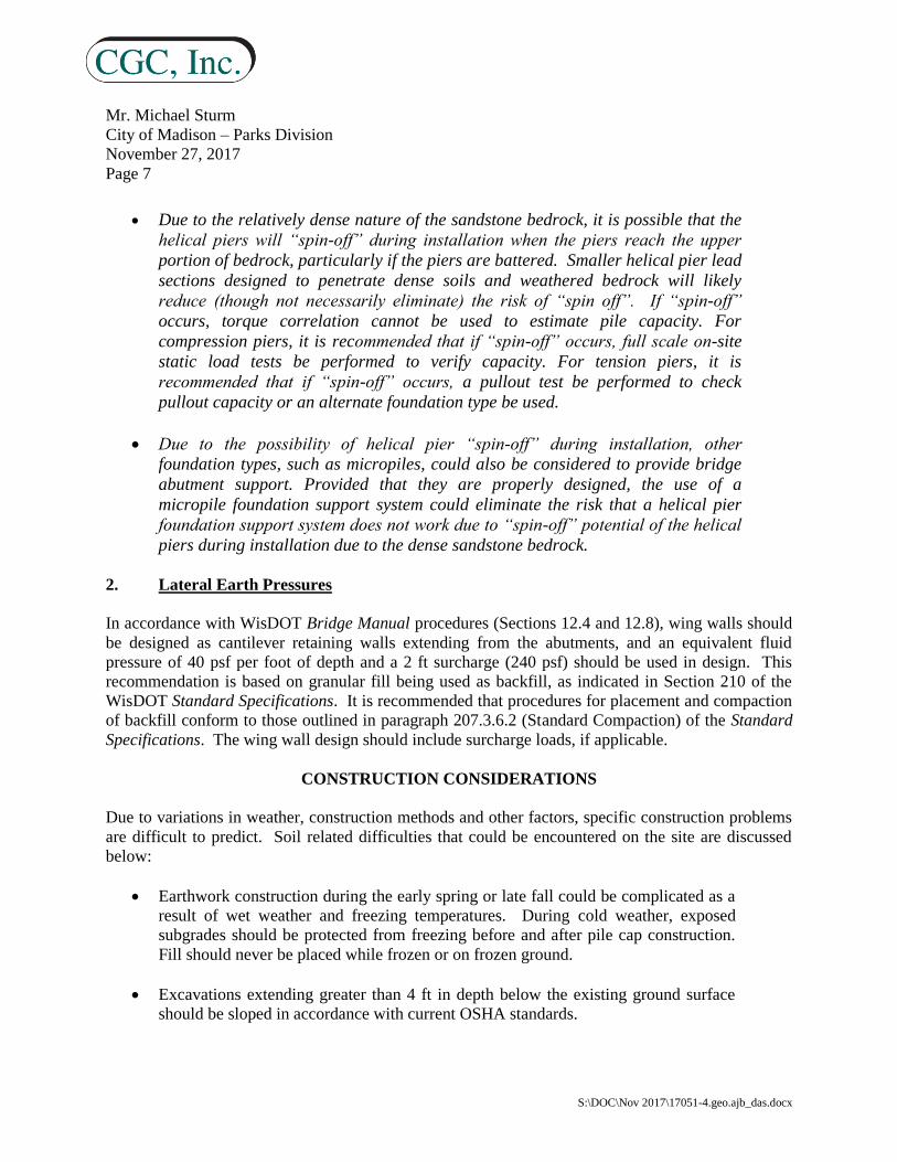
Due to the relatively dense nature of the sandstone bedrock, it is possible that the
helical piers will “spin-off” during installation when the piers reach the upper
portion of bedrock, particularly if the piers are battered. Smaller helical pier lead
sections designed to penetrate dense soils and weathered bedrock will likely
reduce (though not necessarily eliminate) the risk of “spin off”. If “spin-off”
occurs, torque correlation cannot be used to estimate pile capacity. For
compression piers, it is recommended that if “spin-off” occurs, full scale on-site
static load tests be performed to verify capacity. For tension piers, it is
recommended that if “spin-off” occurs, a pullout test be performed to check
pullout capacity or an alternate foundation type be used.
Due to the possibility of helical pier “spin-off” during installation, other
foundation types, such as micropiles, could also be considered to provide bridge
abutment support. Provided that they are properly designed, the use of a
micropile foundation support system could eliminate the risk that a helical pier
foundation support system does not work due to “spin-off” potential of the helical
piers during installation due to the dense sandstone bedrock.
2. Lateral Earth Pressures
In accordance with WisDOT Bridge Manual procedures (Sections 12.4 and 12.8), wing walls should
be designed as cantilever retaining walls extending from the abutments, and an equivalent fluid
pressure of 40 psf per foot of depth and a 2 ft surcharge (240 psf) should be used in design. This
recommendation is based on granular fill being used as backfill, as indicated in Section 210 of the
WisDOT Standard Specifications. It is recommended that procedures for placement and compaction
of backfill conform to those outlined in paragraph 207.3.6.2 (Standard Compaction) of the Standard
Specifications. The wing wall design should include surcharge loads, if applicable.
CONSTRUCTION CONSIDERATIONS
Due to variations in weather, construction methods and other factors, specific construction problems
are difficult to predict. Soil related difficulties that could be encountered on the site are discussed
below:
Earthwork construction during the early spring or late fall could be complicated as a
result of wet weather and freezing temperatures. During cold weather, exposed
subgrades should be protected from freezing before and after pile cap construction.
Fill should never be placed while frozen or on frozen ground.
Excavations extending greater than 4 ft in depth below the existing ground surface
should be sloped in accordance with current OSHA standards.

Mr. Michael Sturm
City of Madison – Parks Division
November 27, 2017
Page 8
S:\DOC\Nov 2017\17051-4.geo.ajb_das.docx
Based on observations made during the field exploration and depending on final
abutment elevations, groundwater will likely be encountered during abutment
excavation. Temporary cofferdams and dewatering inside the cofferdams will likely
be required so that construction can occur “in the dry” during pile driving or helical
pier installation and abutment construction. Additional water accumulating at the
base of the excavation should be controlled and removed using pumps operating
from filtered sump pits. A layer of clear stone at the bottom of the excavation may be
useful for creating a working platform and also assist in dewatering efforts.
RECOMMENDED CONSTRUCTION MONITORING
The level of care exercised during site development will largely determine the quality of the
foundations and pavement subgrades on the approaches. To check that earthwork and foundation
construction proceeds in accordance with our recommendations, qualified construction inspectors
should monitor the following operations:
Pile driving observations;
Abutment fill/backfill placement and compaction; and
Concrete placement.
* * * * *
Mr. Michael Sturm
City of Madison – Parks Division
November 27, 2017
Page 9
S:\DOC\Nov 2017\17051-4.geo.ajb_das.docx
We trust this report addresses your present needs. General limitations regarding the conclusions and
opinions presented in this report are discussed in Appendix B. If you have any questions, please
contact us.
Sincerely,
CGC, Inc.
Alex J. Bina, P.E.
Staff Engineer
David A. Staab, P.E., LEED AP
Consulting Professional
Encl: Appendix A - Subsurface Exploration
Appendix B - Soil Boring Location Exhibit
Logs of Test Borings (4)
Log of Test Boring-General Notes
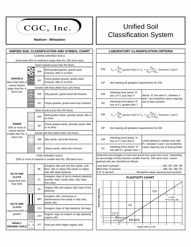
Unified Soil Classification System
Appendix C - Document Qualifications

APPENDIX A
SUBSURFACE EXPLORATION

APPENDIX A
SUBSURFACE EXPLORATION
Subsurface conditions in the vicinity of the proposed bridge abutments were explored by drilling four
Standard Penetration Test (SPT) borings to depths of 24 to 39 ft below existing site grades. Note that
the borings were originally planned to extend to depths of 50 to 100 ft, but were stopped short after
extending the borings 10 to 25 ft into the dense to very dense, apparent sandstone bedrock. The
borings were drilled by Badger State Drilling (under subcontract to CGC) on February 13 and 14,
2017 using an ATV-mounted D-50 drill-rig equipped with hollow-stem augers and an automatic SPT
hammer. The boring locations and planned depths were selected by CGC in consultation with the
City, and were located in the field by CGC based off a map provided by the City. Ground surface
elevations at the boring locations were estimated by CGC using an online mapping tool (DCiMap)
and should be considered approximate (± 1 ft). The boring locations are shown in plan on the Soil
Boring Location Exhibit attached in Appendix A.
Soil samples were obtained at 2.5-foot intervals to a depth of 10 ft and at 5-foot intervals thereafter.
The soils samples were obtained in general accordance with specifications for standard penetration
testing, ASTM D 1586. The specific procedures used for drilling and sampling are described below:
1. Boring Procedures Between Samples
The boring is extended downward, between samples, by a hollow stem auger. Before
encountering groundwater, the drilling method is switched to mud rotary and the hole is
advanced with a roller bit.
2. Standard Penetration Test and Split-Barrel Sampling of Soils
(ASTM Designation: D 1586)
This method consists of driving a 2-inch outside diameter split barrel sampler using a 140-pound
weight falling freely through a distance of 30 inches. The sampler is first seated 6 inches into the
material to be sampled and then driven 12 inches. The number of blows required to drive the
sampler the final 12 inches is recorded on the log of borings and known as the Standard Penetration
Resistance. Recovered samples are first classified as to texture by the driller.
Field screening of the soil samples for possible environmental contaminants was not conducted by
the drillers, as environmental site assessment activities were not part of CGC's work scope. Upon
completion of drilling, the borings were backfilled to satisfy WDNR requirements, and soil samples
delivered to our laboratory for visual classification and laboratory testing. The soils were visually
classified by a geotechnical engineer using the Unified Soil Classification System. The final logs
prepared by the engineer and a description of the Unified Soil Classification System are presented in
Appendix B.

APPENDIX B
SOIL BORING LOCATION EXHIBIT
LOGS OF TEST BORINGS (4)
LOG OF TEST BORING – GENERAL NOTES
UNIFIED SOIL CLASSIFICATION SYSTEM


LOG OF TEST BORING General Notes
SYMBOLS
Drilling and Sampling
CS – Continuous Sampling RC – Rock Coring: Size AW, BW, NW, 2”W RQD – Rock Quality Designation RB – Rock Bit/Roller Bit FT – Fish Tail DC – Drove Casing C – Casing: Size 2 ½”, NW, 4”, HW CW – Clear Water DM – Drilling Mud HSA – Hollow Stem Auger FA – Flight Auger HA – Hand Auger COA – Clean-Out Auger SS - 2” Dia. Split-Barrel Sample 2ST – 2” Dia. Thin-Walled Tube Sample 3ST – 3” Dia. Thin-Walled Tube Sample PT – 3” Dia. Piston Tube Sample AS – Auger Sample WS – Wash Sample PTS – Peat Sample PS – Pitcher Sample NR – No Recovery S – Sounding PMT – Borehole Pressuremeter Test VS – Vane Shear Test WPT – Water Pressure Test
Laboratory Tests qa – Penetrometer Reading, tons/sq ft qa – Unconfined Strength, tons/sq ft W – Moisture Content, % LL – Liquid Limit, % PL – Plastic Limit, % SL – Shrinkage Limit, % LI – Loss on Ignition D – Dry Unit Weight, lbs/cu ft pH – Measure of Soil Alkalinity or Acidity FS – Free Swell, %
Water Level Measurement
- Water Level at Time Shown NW – No Water Encountered WD – While Drilling BCR – Before Casing Removal ACR – After Casing Removal CW – Cave and Wet CM – Caved and Moist Note: Water level measurements shown on the boring logs represent conditions at the time indicated and may not reflect static levels, especially in cohesive soils.
DESCRIPTIVE SOIL CLASSIFICATION
Grain Size Terminology
Soil Fraction Particle Size U.S. Standard Sieve Size Boulders ............................... Larger than 12” ..................... Larger than 12”
Cobbles ................................ 3” to 12” ............................... 3” to 12”
Gravel: Coarse..................... ¾” to 3” ............................... ¾” to 3”
Fine ......................... 4.76 mm to ¾” ....................... #4 to ¾”
Sand: Coarse ....................... 2.00 mm to 4.76 mm.............. #10 to #4
Medium ................... 0.42 to mm to 2.00 mm ......... #40 to #10
Fine ......................... 0.074 mm to 0.42 mm ............ #200 to #40
Silt ......................................... 0.005 mm to 0.074 mm .......... Smaller than #200
Clay ....................................... Smaller than 0.005 mm ......... Smaller than #200
Plasticity characteristics differentiate between silt and clay.
General Terminology Relative Density Physical Characteristics Term “N” Value
Color, moisture, grain shape, fineness, etc. Very Loose…….… . 0 - 4
Major Constituents Loose……………… 4 - 10
Clay, silt, sand, gravel Medium Dense…...10 - 30
Structure Dense……………...30 - 50
Laminated, varved, fibrous, stratified, Very Dense……….Over 50
cemented, fissured, etc.
Geologic Origin
Glacial, alluvial, eolian, residual, etc.
Relative Proportions Of Cohesionless Soils Consistency Proportional Defining Range by Term qu-tons/sq. ft
Term Percentage of Weight Very Soft……….. 0.0 to 0.25
Soft…………..…. 0.25 to 0.50 Trace.................................0% - 5% Medium………..…0.50 to 1.0 Little .............................. 5% - 12% Stiff…………….…. 1.0 to 2.0
Some ........................... 12% - 35% Very Stiff………..... 2.0 to 4.0
And ............................. 35% - 50% Hard……….………...Over 4.0
Organic Content by
Combustion Method Plasticity
Soil Description Loss on Ignition Term Plastic Index
Non Organic…………………Less than 4% None to Slight……......0 - 4 Organic Silt/Clay……………4 – 12% Slight………………......5 - 7
Sedimentary Peat………….12% - 50% Medium……………......8 - 22
Fibrous and Woody Peat… More than 50% High to Very High .. Over 22
The penetration resistance, N, is the summation of the number of blows
required to effect two successive 6” penetrations of the 2” split-barrel
sampler. The sampler is driven with a 140 lb. weight falling 30” and is seated
to a depth of 6” before commencing the standard penetration test.
Clean Gravels (Less than 5% fines)
Gravels with fines (More than 12% fines)
Clean Sands (Less than 5% fines)
Sands with fines (More than 12% fines)
Madison - Milwaukee
PT Peat and other highly organic soils
MHInorganic silts, micaceous or
diatomaceous fine sandy or silty soils,
elastic silts
OHOrganic clays of medium to high plasticity,
organic silts
ML
Inorganic silts and very fine sands, rock
flour, silty or clayey fine sands or clayey
silts with slight plasticity
OLOrganic silts and organic silty clays of low
plasticity
Atterberg limits below "A"
line or P.I. less than 4
Atterberg limits above "A"
line with P.I. greater than 7
Well-graded gravels, gravel-sand
mixtures, little or no fines
Well-graded sands, gravelly sands, little or
no fines
Poorly graded sands, gravelly sands, little
or no fines
Silty gravels, gravel-sand-silt mixtures
Poorly-graded gravels, gravel-sand
mixtures, little or no fines
Clayey sands, sand-clay mixtures
Atterberg limts above "A"
line or P.I. greater than 7
SW
SP Not meeting all gradation requirements for GW
Classification System
Unified Soil
SILTS AND
CLAYS
Liquid limit 50% or
greater
CH Inorganic clays of high plasticity, fat clays
FINE-GRAINED SOILS
(50% or more of material is smaller than No. 200 sieve size.)
SILTS AND
CLAYS
Liquid limit less
than 50%
CL
LABORATORY CLASSIFICATION CRITERIA
HIGHLY
ORGANIC SOILS
COARSE-GRAINED SOILS
(more than 50% of material is larger than No. 200 sieve size)
Inorganic clays of low to medium plasticity,
gravelly clays, sandy clays, silty clays,
lean clays
SM Silty sands, sand-silt mixtures
SW
SP
GM
GP
UNIFIED SOIL CLASSIFICATION AND SYMBOL CHART
Clayey gravels, gravel-sand-clay mixtures
Determine percentages of sand and gravel from grain-size curve. Depending
on percentage of fines (fraction smaller than No. 200 sieve size), coarse-
grained soils are classified as follows:
Less than 5 percent …………………………………………... GW, GP, SW, SP
More than 12 percent …….………………..….………………. GM, GC, SM, SC
5 to 12 percent ………………..….... Borderline cases requiring dual symbols
GP Not meeting all gradation requirements for GW
GW
GMAtterberg limts below "A"
line or P.I. less than 4
GC
Above "A" line with P.I. between 4
and 7 are borderline cases requiring
use of dual symbols
Limits plotting in shaded zone with
P.I. between 4 and 7 are borderline
cases requiring use of dual symbols
SM
SC
GW
50% or more of
coarse fraction
smaller than No. 4
sieve size
SANDS
More than 50% of
coarse fraction
larger than No. 4
sieve size
GRAVELS
GC
SC
Cu =D60
D10greater than 4; CC =
D30
D10 × D60between 1 and 3
Cu =D60
D10greater than 4; CC =
D30
D10 × D60between 1 and 3

APPENDIX C
DOCUMENT QUALIFICATIONS

CGC, Inc. 07/01/2016
APPENDIX C
DOCUMENT QUALIFICATIONS
I. GENERAL RECOMMENDATIONS/LIMITATIONS
CGC, Inc. should be provided the opportunity for a general review of
the final design and specifications to confirm that earthwork and
foundation requirements have been properly interpreted in the design
and specifications. CGC should be retained to provide soil
engineering services during excavation and subgrade preparation.
This will allow us to observe that construction proceeds in
compliance with the design concepts, specifications and
recommendations, and also will allow design changes to be made in
the event that subsurface conditions differ from those anticipated
prior to the start of construction. CGC does not assume responsibility
for compliance with the recommendations in this report unless we are
retained to provide construction testing and observation services.
This report has been prepared in accordance with generally accepted
soil and foundation engineering practices and no other warranties are
expressed or implied. The opinions and recommendations submitted
in this report are based on interpretation of the subsurface
information revealed by the test borings indicated on the location
plan. The report does not reflect potential variations in subsurface
conditions between or beyond these borings. Therefore, variations in
soil conditions can be expected between the boring locations and
fluctuations of groundwater levels may occur with time. The nature
and extent of the variations may not become evident until
construction.
II. IMPORTANT INFORMATION
ABOUT YOUR
GEOTECHNICAL ENGINEERING REPORT
Subsurface problems are a principal cause of construction delays,
cost overruns, claims, and disputes. While you cannot eliminate all
such risks, you can manage them. The following information is
provided to help.
Geotechnical engineers structure their services to meet the specific
needs of their clients. A geotechnical engineering study conducted
for a civil engineer may not fulfill the needs of a construction
contractor or even another civil engineer. Because each geotechnical
engineering study is unique, each geotechnical engineering report is
unique, prepared solely for the client. No one except you should rely
on your geotechnical engineering report without first conferring with
the geotechnical engineer who prepared it. And no one - not even you
- should apply the report for any purpose or project except the one
originally contemplated.
READ THE FULL REPORT
Serious problems have occurred because those relying on a
geotechnical engineering report did not read it all. Do not rely on an
executive summary. Do not read selected elements only.
A GEOTECHNICAL ENGINEERING REPORT IS BASED ON
A UNIQUE SET OF PROJECT-SPECIFIC FACTORS
Geotechnical engineers consider a number of unique, project-specific
factors when establishing the scope of a study. Typical factors
include: the client’s goals, objectives, and risk management
preferences; the general nature of the structure involved, its size, and
configuration; the location of the structure on the site; and other
planned or existing site improvements, such as access roads, parking
lots, and underground utilities. Unless the geotechnical engineer who
conducted the study specifically indicates otherwise, do not rely on a
geotechnical engineering report that was:
• not prepared for you,
• not prepared for your project,
• not prepared for the specific site explored, or
• completed before important project changes were made.
Typical changes that can erode the reliability of an existing
geotechnical report include those that affect:
• the function of the proposed structure, as when it’s changed
from a parking garage to an office building, or from a light
industrial plant to a refrigerated warehouse,
• elevation, configuration, location, orientation, or weight of the
proposed structure,
• composition of the design team, or project ownership.
As a general rule, always inform your geotechnical engineer of
project changes - even minor ones - and request an assessment of
their impact. CGC cannot accept responsibility or liability for
problems that occur because our reports do not consider
developments of which we were not informed.
SUBSURFACE CONDITIONS CAN CHANGE
A geotechnical engineering report is based on conditions that existed
at the time the geotechnical engineer performed the study. Do not
rely on a geotechnical engineering report whose adequacy may have
been affected by: the passage of time; by man-made events, such as
construction on or adjacent to the site; or by natural events, such as
floods, earthquakes, or groundwater fluctuations. Always contact the
geotechnical engineer before applying the report to determine if it is
still reliable. A minor amount of additional testing or analysis could
prevent major problems.
MOST GEOTECHNICAL FINDINGS ARE PROFESSIONAL
OPINION
Site exploration identifies subsurface conditions only at those points
where subsurface tests are conducted or samples are taken.
Geotechnical engineers review field and laboratory data and then
apply their professional judgement to render an opinion about
subsurface conditions throughout the site. Actual subsurface
conditions may differ - sometimes significantly - from those
indicated in your report. Retaining the geotechnical engineer who
developed your report to provide construction observation is the most

CGC, Inc. 07/01/2016
effective method of managing the risks associated with unanticipated
conditions.
A REPORT’S RECOMMENDATIONS ARE NOT FINAL
Do not over-rely on the confirmation-dependent recommendations
included in your report. Those confirmation-dependent
recommendations are not final, because geotechnical engineers
develop them principally from judgement and opinion. Geotechnical
engineers can finalize their recommendations only by observing
actual subsurface conditions revealed during construction. CGC
cannot assume responsibility or liability for the report’s
confirmation-dependent recommendations if we do not perform the
geotechnical-construction observation required to confirm the
recommendations’ applicability.
A GEOTECHNICAL ENGINEERING REPORT IS SUBJECT
TO MISINTERPRETATION
Other design team members’ misinterpretation of geotechnical
engineering reports has resulted in costly problems. Confront that
risk by having your geotechnical engineer confer with appropriate
members of the design team after submitting the report. Also retain
your geotechnical engineer to review pertinent elements of the design
team’s plans and specifications. Constructors can also misinterpret a
geotechnical engineering report. Confront that risk by having CGC
participate in prebid and preconstruction conferences, and by
providing geotechnical construction observation.
DO NOT REDRAW THE ENGINEER’S LOGS
Geotechnical engineers prepare final boring and testing logs based
upon their interpretation of field logs and laboratory data. To prevent
errors or omissions, the logs included in a geotechnical engineering
report should never be redrawn for inclusion in architectural or other
design drawings. Only photographic or electronic reproduction is
acceptable, but recognize that separating logs from the report can
elevate risk.
GIVE CONSTRUCTORS A COMPLETE REPORT AND
GUIDANCE
Some owners and design professionals mistakenly believe they can
make constructors liable for unanticipated subsurface conditions by
limiting what they provide for bid preparation. To help prevent
costly problems, give constructors the complete geotechnical
engineering report, but preface it with a clearly written letter of
transmittal. In that letter, advise constructors that the report was not
prepared for purposes of bid development and that the report’s
accuracy is limited; encourage them to confer with the geotechnical
engineer who prepared the report (a modest fee may be required)
and/or to conduct additional study to obtain the specific types of
information they need or prefer. A prebid conference can also be
valuable. Be sure constructors have sufficient time to perform
additional study. Only then might you be in a position to give
constructors the best information available to you, while requiring
them to at least share some of the financial responsibilities stemming
from unanticipated conditions.
READ RESPONSIBILITY PROVISIONS CLOSELY
Some clients, design professionals, and constructors do not recognize
that geotechnical engineering is far less exact than other engineering
disciplines. This lack of understanding has created unrealistic
expectations that have led to disappointments, claims, and disputes.
To help reduce the risk of such outcomes, geotechnical engineers
commonly include a variety of explanatory provisions in their
reports. Sometimes labeled “limitations,” many of these provisions
indicate where geotechnical engineer’s responsibilities begin and end,
to help others recognize their own responsibilities and risks. Read
these provisions closely. Ask questions. Your geotechnical engineer
should respond fully and frankly.
ENVIRONMENTAL CONCERNS ARE NOT COVERED
The equipment, techniques, and personnel used to perform an
environmental study differ significantly from those used to perform a
geotechnical study. For that reason, a geotechnical engineering
report does not usually relate any environmental findings,
conclusions, or recommendations; e.g., about the likelihood of
encountering underground storage tanks or regulated contaminants.
Unanticipated environmental problems have led to numerous project
failures. If you have not yet obtained your own environmental
information, ask your geotechnical consultant for risk management
guidance. Do not rely on an environmental report prepared for
someone else.
OBTAIN PROFESSIONAL ASSISTANCE TO DEAL WITH
MOLD
Diverse strategies can be applied during building design,
construction, operation, and maintenance to prevent significant
amounts of mold from growing on indoor surfaces. To be effective,
all such strategies should be devised for the express purpose of mold
prevention, integrated into a comprehensive plan, and executed with
diligent oversight by a professional mold prevention consultant.
Because just a small amount of water or moisture can lead to the
development of severe mold infestations, many mold prevention
strategies focus on keeping building surfaces dry. While
groundwater, water infiltration, and similar issues may have been
addressed as part of the geotechnical engineering study whose
findings are conveyed in this report, the geotechnical engineer in
charge of this project is not a mold prevention consultant; none of the
services performed in connection with the geotechnical engineer’s
study were designed or conducted for the purpose of mold
prevention. Proper implementation of the recommendations
conveyed in this report will not of itself be sufficient to prevent mold
from growing in or on the structure involved.
RELY ON YOUR GEOTECHNICAL ENGINEER FOR
ADDITIONAL ASSISTANCE
Membership in the Geotechnical Business Council (GBC) of
Geoprofessional Business Association exposes geotechnical
engineers to a wide array of risk confrontation techniques that can be
of genuine benefit for everyone involved with a construction project.
Confer with CGC, a member of GBC, for more information.
Modified and reprinted with permission from:
Geotechnical Business Council
of the Geoprofessional Business Association
8811 Colesville Road, Suite G 106
Silver Spring, MD 20910

?
847
847
847847
849
849
849E
E
E
850
850
850
850
850850
852
852
852
852
852
854
854
854
856
856
BOTTOM
LAGOON
SHEET
JOB NO.
PROJECT MGR.
NO.
RE
VIS
ION
SD
AT
E:
A S S O C I A T E S ®
TE
MP.
FO
RD C
RO
SSIN
G D
ET
AIL
S
V
ILA
S P
AR
K - L
AG
OO
N B
RID
GE R
EP
LA
CE
ME
NT
S
C
ITY O
F M
ADIS
ON P
AR
KS D
IVIS
ION
M
ADIS
ON,
WIS
CO
NSIN
1020.103
KRB
15
S:\MAD\1000--1099\1020\103\Micros\Plan\15-Temp Ford Crossing Details.dgn user: dimitriosh 11/15/2017 2:49:31 PM
TEMP FORD CROSSING PLAN
STONE
3" CLEAR
FABRIC TYPE HR
RIPRAP FILTER
2
1
BARRIER
TURBIDITY BARRIER
TURBIDITY
NORTH BRIDGE
(TYP.)
SILT FENCE
(10-17-2016)
EL. 847.92
NORMAL WATER
(10-17-2016)
EL. 847.92
NORMAL WATER
WATER
EDGE OF
FABRIC TYPE HR
RIPRAP FILTER
STONE
3" CLEAR
SECTION A-A
SECTION B-B
B
B
BARRIER (TYP.)
TURBIDITY
A
A
B
B
FABRIC TYPE HR
OVER RIPRAP FILTER
3" CLEARSTONE
6"
12'-0"
(TYP.)
1'-0"
MIN.
5'-0"
6"
MIN.
6"
11-27-17
1A
dden
dum
1