madras: multi-architecture binary rewriting tool technical … · madras: multi-architecture binary...
TRANSCRIPT

MADRAS: Multi-Architecture Binary Rewriting
Tool
Technical report
Cedric ValensiUniversity of Versailles Saint-Quentin en Yvelines
September 2, 2013

Chapter 1
Introduction
In the domain of High Performance Computing, performances are obtained inthe price of an increased complexity at all steps of a program life cycle, fromthe compilation chain to the processor internal architecture. While the need toimprove performances is still critical, this complexity has made this task evenmore difficult. The field of performance analysis aims at finding the best way toprofile the behaviour of HPC applications in order to identify their bottlenecks,their causes, and how to improve them.
A possible way of achieving this is through the analysis of the source codeof applications. While this is one of the easiest methods, it is not not the mostprecise nor reliable. In order to take advantage of the architecture abilities, com-pilers can perform extensive code transformations when generating the binaryexecutable from the source code, like loop unrolling or constant propagation.These transformations may significantly alter the control flow of a program fromits source representation and render most deductions made from the analysisof the source code incomplete at best. It may also be interesting to identifywhich transformations were performed by the compiler, in order to detect in-teresting transformations that were missed because of the way the algorithmwas expressed in the source code. Finally, the source code of an applicationmay not be fully available for analysis, for instance because of confidentialityrestrictions.
It is also not always possible to retrieve all useful informations from a staticanalysis of the code. Some of them, like the timings of code segments, can notbe deduced from such an analysis without a significant error margin, if at all. Itmay therefore be useful to be able to perform transformations on the program,such as inserting probes, in order to retrieve additional informations at runtime. Performing such transformations in the source code can however impactthe compilation process and alter the program behaviour, as the compiler willtake the altered code into account when performing its optimisations. Thismay lead to very different performances from the original, thus voiding theinformations gained from those transformations.
It is therefore interesting to be able to directly analyse the assembly code
1

generated by the compiler, since this is what will be actually be executed by theprocessor. Most compilers allow to generate assembly files instead of binariesfrom a source file. However, it is usually not possible to generate such a filefor the whole program if it was compiled from multiple source files, which isthe case for most real applications. This will not be possible either when thesource is not available. Additionally, while it is much closer to what will beactually executed by the processor than the source code, an assembly file maylack some informations useful for analysis. For instance, the assembler may addpadding instructions for alignment when converting the assembly code to binary,which could have a non negligible impact on the overall execution time. Also,some informations found only by analysing the binary code, like the length ofinstructions, may be needed by analysis, for instance to compare with the sizeof the instruction cache. Finally, if the code must be instrumented, it will stillneed to be assembled after modifying those assembly files.
Figure 1.1: Location of binary analysis in the compilation chain of an executable
The solution would be to directly process the binary file, for analysis and forinstrumentation, as illustrated in figure 1.1. This implies being able to decodethe binary code in the file back into assembler code through disassembly. In-strumentation would be performed by directly modifying the binary file throughpatching.
Disassembling presents multiple challenges, since a binary file, being in-tended for the processor, may lack some informations useful to human beingsto analyse its contents, or require some additional processing to retrieve. Asfor patching, since a binary executable, unlike a linkable file, is not intended tobe modified, its internal structure can make changes complex to perform whilekeeping the executable functional.
In this report, we present MADRAS (Multi Architecture Disassembler Rewriterand Assembler), a tool allowing to disassemble and patch binary files and avail-
2

able as an API. The disassembler functionality allows to decode the assemblyinstructions contained in the file and build structures representing them, whilethe patcher functionality allows to modify the assembly instructions in the fileand save the result as a new binary executable.
Figure 1.2: Global description of the MADRAS tool
MADRAS relies on MINJAG to generate the architecture specific files usedby the disassembler and assembler, ensuring an easy implementation of otherarchitectures and update of existing ones.
1.1 Organisation
Chapter 2 describes the overall structure of binary files and assembly languages,and briefly presents different architectures.
Chapter 3 focuses on disassembly, presenting its challenges and commonsolutions, as well as our implementation choices and future works.
Chapter 4 focuses on patching, describing the challenges and common solu-tions to patching files, our choices for addressing them, and the future works onthis subject.
Chapter 5 concludes this report.Annexes contain a detailed description of the MADRAS API in annex A,
the algorithms used by the disassembler in annex B and by the patcher in annexC.
3

Chapter 2
Context
Binary executable files share common characteristics across architectures andplatforms that need to be taken into account when analysing and modifyingthem. In this chapter, we will briefly present these characteristics, focusing onthose more likely to present issues when disassembling or patching files.
2.1 Binary executable
An executable is a binary file with a specific format allowing the operatingsystem to identify how to load it into memory and execute it. The same format isusually used for relocatable files, which are used as intermediary files generatedby a compiler and used by the linker to generate an executable, and libraryfiles, which contain common shared code usable by executables. This formatcan also be used for representing dump files, generated after a program crashfor debugging.
A binary executable contains all the informations needed for its execution.It can however rely on external libraries for the definition of some functionsor variables. Those executables are called dynamic executables. Stand-aloneexecutables are called static executables.
A relocatable file contains compiled code, and informations used by the linkerto generate a functional executable from it and other related files.
2.1.1 General structure
Executable files commonly contain the following elements:
• Format identifier (“magic word”)
• Header describing the structure of the file
• Binary code to execute
• Variables used by the code
4

• Directives for the OS on how to load and execute the file
• Relocation tables
• Informations on how to invoke external functions for dynamic executables
• Optionally:
– Debug informations, added if requested by the compiler
– Labels, depending on compiler settings.
In most binary formats, files are broken down into sections. A section con-tains one given type of data, like code, variables, relocation, etc., and otherspecific informations, such as the virtual addresses where the data and codemust be loaded when executing the file and the rights to set on the memorysegments where it is loaded. It is possible that a section is not loaded intomemory when running the program, if its contents are not needed by the exe-cutable. Sections are identified by a header specifying at which offset in the filethe section’s data is contained.
Some formats also use the concept of segments, regrouping one more moresections. In these cases, segments are used by the loader, while sections are usedby the linker when building the file.
2.1.2 Symbols
Binary files can contain symbols, which are strings associated to an addressand possibly a type characterising what they represent. They can be used toreference specific locations in the file such as the beginning of a function inthe code section or a variable in the data section. Most of those symbols arehowever not needed by an executable file, and as such may be removed withoutaffecting its behaviour. The most important exception to this are relocations(see 2.1.4), which explicitly need a symbol to be performed.
It is also important to note that, while a binary format may define specifictypes for identifying the uses of a symbol, those are not mandatory either. Itis therefore possible for a binary file to contain symbols actually correspondingto the beginning of functions, but being identified with a generic non indicativetype.
The compilers for certain languages, like C++ or Fortran, use the conceptof name mangling, where the symbols stored in a binary file are not the sameas those used for a variable or function name as they appear in the source code,but are instead run through an encoding (mangling) algorithm. In this case,it is necessary to decode the names found in the file to retrieve the originalnames. The algorithm used to mangle the names depends on the language andthe compiler used to generate the file. [38] presents some of those algorithms,which are not always available and may require some reverse engineering toretrieve.
5

2.1.3 Variables
An executable can contain variables, usually those that may be accessed fromanywhere in the program (global variables) or have a fixed value, such as acharacter string or a branch table used by a switch operation; dynamically-allocated variables are not defined in an executable. Variables that can be reador written are usually in a different section or segment than those that are readonly, allowing to set the appropriate rights on it at run time.
Some systems may adopt a special behaviour in regard to variables whosevalue is not initialised at compilation time. Those variables are defined in aspecial section that does not take any space in the file, but whose attributesspecify a size in memory. The loader is responsible for allocating the necessaryspace for those sections when loading the file in memory.
2.1.4 Relocation
Relocation is the process of updating a reference address in a file after it wasgenerated. Relocations are usually performed through a relocation table whichreferences a location in the code or data and the symbol to which it is linked.When the address of the symbol is known, the reference will be updated accord-ingly. It is mostly used by the linker during compilation: a compiled relocatablefile will contain relocation tables for all external symbols, which will be used bythe linker to reference the code or data corresponding to those symbols.
Relocation can also be used at run time when executing a file dependingon external resources, like shared libraries. In this case, the loader will beresponsible for resolving the location of the symbol referenced by the relocationand update the loaded code accordingly.
2.1.5 Referencing an external source
Most recent file formats allow to reference code or variables defined in an ex-ternal file. The most common use for this the invocation of functions definedin a shared library. The address at which the external reference is loaded inmemory is not known when the executable is generated, so a relocation table(as described in 2.1.4) must be used. References to an external source are usu-ally redirected to a specific section linked to a relocation table. Depending onthe system and properties of the executable, the addresses can be filled eitherduring program loading or when they are accessed for the first time.
2.1.6 Debug information
Debug informations are not needed for a standard program execution a program,but are used when running it through a debugger utility. They are usually storedin a separate section that may not be loaded into memory when running theprogram. The format of those sections may be independent from the formatrepresenting the executable.
6

Debug informations aim at allowing the debugger to establish the relationbetween the source code and the binary file, and as such can contain corre-spondences between binary addresses and lines in the source code, or betweenmemory locations and variable names.
2.1.7 Common binary formats
Here is a quick overview of the most important binary formats. We will focusmore closely on ELF as it is the format with which we worked more extensively.
The a.out format
The a.out [6] format, used on older Unix systems, is one of the first format forbinary files. It has been now mostly replaced by the COFF then ELF formatsin the Unix/Linux environment. However, it presents most of the core conceptsused in more modern formats.
a.out files are broken down into sections, containing the executable code,symbols, relocations and data. A header contains the sizes of the various sec-tions, and begins with a branch instruction to the entry point of the executablecode. The loader ensures that the program does not run past its size by settinga break at the end of the text and data sections.
The symbols section is used for referencing functions and variables definedin other files. The relocation section is used by the loader to initialise pointersto other files.
More recent variants of the a.out format allow to set the text section as readonly. Debug informations can also be stored in special entries of the symbolsections.
The COFF format
The COFF (Common Object File Format) was introduced on more recent Unixsystems, before being replaced by ELF. It is used by Windows in conjunctionwith PE (see 2.1.7) and some of its variants are used by IBM AIX (XCOFF[29]) or Texas Instrument ([13]).
COFF files are broken down into sections. Sections are identified through aheader containing informations on their respective offsets in the file, sizes, andvirtual addresses where to be loaded into memory. The file contains a headerspecifying where the section header is located in the file, as well as the size ofan optional second file header. This header is used when the file is executableto specify the program entry point and the sizes to load in memory.
A COFF file can also contain a relocation table, and a special section storingline numbers for debugging.
The ELF format
ELF (Executable and Linkable Format [15] [48]) is the format used by the Unixand Linux operating systems. It is used for object files, executable files, library
7

files, and core dump files. ELF is an evolution of the a.out format.The contents of an ELF file can be represented as a table of either sections
or segments, each being identified in a distinct header. The section headeris mandatory in an object file while the program header is mandatory in anexecutable file or a library.
According to the standard, the section header is optional in an executablefile, however compilers routinely keep it in executable files. A segment usuallyencompasses multiple sections, but the standard does not specifies that theboundaries of a segment matches with those of sections.
An ELF file always contains a general header identifying the file type andthe offsets in the file of the sections and/or segments headers.
Segments contain the virtual address at which the corresponding bytes fromthe file must be loaded into memory when executing it, as well as the rights toset on those addresses. A standard ELF executable usually contains a segmentcontaining the program header, a segment describing the interpreter to usewhen executing the file, a readable and executable segment containing the codeand the read-only variables and a readable and writeable segment containingthe read-write variables. Other segments may contain informations relative toexternal libraries for dynamic files.
Sections in an ELF file follow the general description (cf. 2.1.1). Unlike seg-ments, sections can be named. The standard does not impose a strict constrainton sections names, and more than one section can have the same name.
Common sections contain the executable code (usually named “.text”, withthe sections “.init” and “.fini” containing respectively initialisation and termi-nation code), read-only variables (“.rodata”), read-write variables (“.data”),non initialised variables (“.bss”), relocation sections (named by the section theyreference prefixed with “.rela”), and string tables used for labels (“.strtab”),section names (“.shstrtab”) and dynamic symbols (“.dynstr”).
ELF file can contain debug informations, in the DWARF format, usually notloaded when executing the program. DWARF [14] is an independent format nottied to ELF, and the debug informations stored in those sections depend on thecompiler used. Common informations stored are the compiler name and version,the association between line numbers and instructions addresses, the originalfunction names (without the mangling if present), and function parameters,start addresses, and local variables.
The Windows PE format
The PE (Portable Executable) [53] [24] format is used by Windows-based op-erating systems. It is an evolution of the COFF format and is occasionallyreferred to as COFF/PE.
A PE file contains a MS-DOS header, used to display an error message if thefile is run on a system unable to support it. This header also contains the offsetin the file of the PE header. PE files are broken down into sections, identifiedin a section table referenced in the PE header.
Debug informations are stored in the read only data section.
8

The Mach-O format
The Mach-O (Mach Object [27]) format is used by systems based on the Machkernel ([30]), the most prominent being Apple Mac OS X. Like ELF, Mach-Ois an evolution of the a.out format, and both share similar concepts.
Mach-O files are broken down into sections and segments, a segment con-taining zero or more sections. The header specifies at which offsets the varioussections and segments can be found in the file. The header also contains loadcommands allowing to specify additional information about the file, like theshared libraries defining the functions used in a dynamic executable.
The AIF format
AIF (ARM Image Format [8]) is a simple format used for executables, while ALF(ARM Object Library Format) is the corresponding format used for libraries.
AIF files use a header specifying the entry point of the executable, a codeimage and a data image. An AIF executable can relocate itself after beingloaded, using a special self-relocation code and a relocation list stored in thecode image.
2.2 Assembly language
Assembly is a low-level language directly representing the operations performedby the processor. Unlike most compiled languages, assembly is specific to a givenprocessor architecture, as it directly depends on the processor instructions andregisters sets.
An assembly statement is an instruction. Instructions are composed of amnemonic, which is a command to be executed by the processor, and a list ofoperands. Operands can be registers, memory addresses or immediate values.Mnemonics can be roughly categorised between the following operations:
• A numerical operation between the operands
• The affectation of a value, immediate or stored in a register or memoryaddress, to another register or memory address
• Branching of the control flow of the program to a given address
Instructions in a program written in assembly language are executed by theprocessor in the order into which they appear in the assembly source, until abranch instruction is encountered. Assembly language use labels to referencethe destination of branch instructions. Special directives also allow to declaresome labels as functions; this is especially useful for declaring functions intendedto be invoked from a different source, such as in the code for a shared library.
Most assembly languages include a no operation instruction, usually callednop, that does not perform any operation. Such an instruction can be usedas filler to align code or to temporarily stall the processor and ensure data
9

dependencies are broken. Compilers may alternatively use instructions thatdon’t actually affect the control flow nor the data set, like exchanging the contentof a register with itself, in place of the explicit nop instruction.
2.2.1 Binary encoding
The encoding rules for an architecture specify how to translate assembly instruc-tions into binary code, a process called assembly. Those rules usually establisha one-to-one correspondence between both representations, although in somecases different instructions can represent an identical operation, and as suchbe indifferently encoded as one or another. For instance, an instruction whosemnemonic represents the swapping of values between both of its operands canaccept any order between its operands for the same operation, and as such ac-cept different encodings. Some mnemonics can also be homonyms of each others.Finally, some architectures may define macro instructions, that represent morethan one instruction, and as such are assembled into the binary codings of allof these instructions.
In binary code, branch instruction do not use labels to reference their desti-nation, but instead use the address of the destination instruction. The only useof labels in binary code is for relocations tables.
Depending on the architecture, encoded binary instructions can be of dif-ferent length in bits. There are no separations between instructions in binarycode.
2.2.2 Addressing
Branch instructions can use two modes of addressing to identify their destina-tion:
• Direct addressing: the destination is identified by a numerical value rep-resenting either the absolute address of the destination or the offset fromthe current instruction
• Indirect addressing: the destination’s address or offset is stored in a mem-ory or register operand
Similarly, memory addresses are usually identified either as an absolutevalue, the values stored in one or more registers, or the sum of both. How-ever they can also be identified by the offset from the current instruction; such amode is mainly used for referencing memory locations defined in the executable,as the address of dynamically allocated variables would be unknown before run-time and may need a relocation. Some architectures represent these addressesas being based on the program counter or instruction pointer, considered as aread-only register.
10

2.2.3 Overview of different architectures
Below is a quick presentation of some of the most used architectures, focusingmore closely on the Intel x86 architecture as we worked more extensively withit.
Intel x86
The Intel x86 architecture [20, 18, 19], also called IA-32 or x86-32, is a CISCarchitecture used by the Intel processors since the 8086 version. It is also usedby AMD processors [1, 2, 3, 4, 5]. It ensures backward compatibility with allprevious versions of the processors and as such defines more than 1000 differentmnemonics. The architecture undergoes frequent evolutions and new instructionsets are added every year.
x86 assembly instructions accept zero to two operands.Their binary encoding instructions vary between one and fifteen bytes. Among
the factors causing an instruction length to vary are legacy prefixes. An instruc-tion can accept up to four different one byte prefixes in any order, and a givenprefix may appear more than once. Another factor is the length over whichnumerical values are encoded, one to four bytes depending on their values.
One particular specificity is that most direct branch instructions exist in twovariants of different length: one variant is coded on five bytes, with a signedoffset coded on 32 bytes, while the other is coded on two bytes with an offsetencoded on one byte.
x86-64 The x86-64 architecture, also known as AMD64 or x64, is an evolutionof x86 to support 64 bits processors. The Intel x86-64 architecture allows accessto 16 64-bits general purpose registers instead of 8 for x86. It is possible toaccess only the 32, 16 or 8 least significant bits of those registers, thus emulatingregisters with this size, and ensuring backward compatibility for codes usingthose sizes of registers. The SSE extensions allow access to 128 vector registers,and instructions can accept up to three operands. The AVX extension extendsthose registers to 256 bits, with instructions accepting up to four operands.
x86-64 instructions use an additional optional 1 byte prefix (REX) to notifythat an instruction uses 64 bits operands and to access the additional registers.The AVX extension uses another 2 or 3 bytes prefix (VEX), to extend thefunctionalities of the REX prefix and access the new 256 bits registers. Thelatest extension AVX2 allows to access non-contiguous memory addresses toperform gather or scatter operations on vectors.
In x86-64, all direct branch instructions use relative addressing. The ar-chitecture also supports the addressing of memory locations relatively to thecurrent instruction pointer.
Intel Xeon Phi
Intel Xeon Phi [23, 22] is the latest Intel coprocessor architecture. It is basedon Intel x86-64 processors without the SSE nor AVX extensions, and as such no
11

access to the 128 or 256 vector registers, but instead offers access to thirty-two512-bits vector registers.
The memory or vector register operands of a Xeon Phi assembly instructioncan accept a modifier to tweak their use. Such a modifier can either be a flagspecifying conversions to apply to the operand, a cache line eviction hint, or amask, defined in a special register, specifying which elements in a vector will beaffected by the operation.
Some conditional branch instructions in Xeon Phi can accept two operands,representing the destination and a mask specifying the condition to apply tothe branch.
Binary encoding of Xeon Phi instructions uses a four bytes prefix (MVEX) toencode the new features of the architecture. Another specificity is the possibilityof compressing offsets used in memory addresses by dividing the encoded valueby a given factor.
Intel IA64
The Intel Itanium architecture [21], also called IA-64, is a parallel Intel archi-tecture distinct from x86, although IA-64 processors allow to run IA-32 appli-cations. The architecture allows parallelism at the instruction level, and offersspecialised mechanisms for handling conditional execution of instructions.
The architecture defines 128 virtual general purpose 64-bits registers and128 82-bits floating-point registers, which are mapped to a stack of physicalregisters allowing for an easier rotation of registers. Other registers are usedfor storing the result of compare instructions and the target address of indirectbranch instructions.
Itanium instructions accept at least three operands, and use a predicate foridentifying if the result of the instructions shall be kept or discarded. Instruc-tions are grouped into bundles, composed of three instructions and a templatespecifying the type of instructions it contains.
In binary, all instructions are encoded on a fixed length of 41 bits, and thetemplates on five bits, thus making the encoding of a bundle 128 bits long.
Power ISA
Power ISA [28], evolved from the PowerPC, is a RISC architecture used by IBMand Motorola processors. It is used in home computers and in HPC. It offers 32and 64 bits modes. The instruction set is stable and undergoes little evolution.
All Power ISA instructions are 32 bits long and must be word aligned. Afield in an instruction coding may be split over multiple location in the coding.
ARM
The ARM architecture [12, 9, 10, 11, 7] is a RISC architecture designed andlicensed by ARM Holdings and used by various processors. It is mainly usedin mobile systems but also involved in ongoing HPC projects.The architecturesundergoes frequent evolutions, with new versions released on a yearly basis.
12

ARM processors support three instruction sets: ARM, which defines 32-bitsinstructions, Thumb, which defines 16 or 32-bits instructions, and A64 (fromARMv8 onwards), which defines 64-bits instructions.
Instructions from the ARM and A64 instruction set are always encoded ona fixed length of 32 bits and aligned on a four bytes boundary. Most ARMinstructions are prefixed with a condition specifying whether the instructionmust actually be executed. When present, this condition is always encoded onthe five first bits. The binary template of the instructions depends on theirfamily: branch, data processing, load/store...
Instructions from the Thumb instruction set are encoded either on 32 or 16bits and aligned on a two bytes boundary. The first five bits of an instructionallow to identify its size. Branch instructions exist in the 16 and 32 bits version.
13

Chapter 3
Disassembly
The process of disassembly consists in the parsing of a binary file in order toretrieve the assembly instructions it contains. It can also be useful to retrieveother informations stored in the file in order to facilitate further analysis ofthe code, such as for instance function labels to have a first insight of functionboundaries. In our context, disassembling a binary file requires to be able toperform the following three operations:
1. Parse the file to extract the relevant sections, especially the code it con-tains
2. Parse the binary code of an instruction and return the corresponding as-sembly instruction
3. Parse a succession of instructions from a binary stream
Step 1. is done through a parser of the binary format into which the file isdefined. We will not focus on this part, as the implementation of such a parser isstraightforward provided the specification of the relevant format is known (Cf.2.1.7 for an overview of most binary formats).
Step 2. requires the implementation of a parser for the architecture forwhich the binary code is defined. In our context, the main concern for thisstage is being able to easily update the parser as the architecture evolves and tominimise the work needed for the implementation of a new architecture. Thoseissues are addressed in [58] and will not be covered here.
Step 3. is the successful application of the binary parser to the binarystreams extracted from the file, and the use of additional informations foundin the file. This task can be complicated if the sections containing binary codealso contain data not representing instructions, which is possible even thoughbinary formats separate code sections from data sections.
In this chapter, we present the challenges of disassembly and our solutions.We will focus first on the challenges from the application of a parser on a binarystream (section 3.1), then describe common algorithms used to solve this as
14

well as present existing disassemblers (section 3.2). We will then present oursolutions for addressing those issues and their implementations (sections 3.3 and3.4), and their possible evolutions (section 3.5).
3.1 Challenges of disassembly
As noted in 2.2.1, the encoding of binary instructions does not include a sep-arating character between instructions. Therefore, for architectures acceptinginstructions of different lengths, the only sure way to reach the beginning ofan instruction is to successfully disassemble the previous one. If the parserused for recognising individual instructions fails to correctly parse an instruc-tion, it may not successfully identify its end, and thus attempt to disassemblethe next instruction while still in the middle of the encoding of an instruction.Such an operation would lead the disassembler to return at least two erroneousinstructions or disassembly errors.
This problem can also occur if the parser functions correctly, but insteadencounters binary data not representing assembly instructions mixed with theregular binary code. Although formats for binary files define separate sectionsfor code and other data, there is nothing to prevent a binary file to mix data andbinary code. In fact, since the only constraint for the execution of a programis that the control flow is not interrupted and the executed code is loaded inmemory space open for execution, it is possible for the executable code to bespread all over the file. In that case, branch instructions will be responsible forkeeping the control flow from reaching areas not containing executable code.
Since disassemblers operate statically, possibly with no information on theinstruction set other than their binary coding, they may miss those branchesand end up attempting to disassemble binary code that does not actually con-tains instructions. This can lead to the disassembler returning parsing errorswhen attempting to process those areas, or incorrectly disassembling correctinstructions that followed such an area. Conversely, since such code can po-tentially take any binary value, the disassembler could be able to successfullyparse such a code into an instruction. It would then return instructions thatare not actually part of the executable code and may lead to further analysisof the executable being incorrect because of those erroneous instructions beingtaken into account.
Such disassembly errors may not be detected easily as some binary formats,especially Intel x86, exhibit properties allowing disassembly to be self-repairing,as demonstrated in [50] and illustrated in [46]. This means that, if the parserfailed to correctly identify the beginning of an instruction due to one of the casesdescribed above, it will eventually resynchronise with the proper boundaries ofinstructions and return subsequent instructions correctly, provided it is still inan area containing executable code. It is therefore possible for the disassemblerto return little to no parsing errors while attempting to disassemble binary codecontaining instructions mixed with other data, making automated detection ofsuch areas complex.
15

Figure 3.1: Example of a disassembly being thrown off course and returningerroneous instructions.
Figure 3.1 presents how a disassembler can return wrong instructions whenattempting to disassemble binary data that does not represent an instruction.The self-repairing properties can also be observed on this example, as the dis-assembler is correctly realigned at the end of the second erroneous instruction.
3.1.1 Common challenges
A common occurrence of binary code representing instructions being mixed withcode representing other information is when data is mixed with code. A codecould for instance contain the value of variables close to the instructions usingthem.
The most common occurrence for this is the use of jump tables, which containthe different possible values for the destination address of an indirect branch(see 2.2.2 and [35]). Such a table allows to avoid multiple conditional branchinstructions since only a calculation of the cell in the array is needed to identifythe target. This mechanism can for instance be a straightforward compilationof a switch statement. Some compilers, like the Intel C compiler icc, use atable mixed with code in customised version of standard functions that are thenadded to the executables it compiles.
Another case where executable code is mixed with other information is whenpadding is used. This can occur when a given instruction needs to be presentat a given address, most likely to satisfy alignment constraints. In that case, acompiler will add binary code before the instruction to ensure such a constraintis satisfied. This code will usually be legitimate instructions (a nop instructionor similar), but can potentially be any other binary code if those alignment
16

instructions are not supposed to be executed (like the example in figure 3.1),for instance if the instruction to be aligned is the beginning of a function andthe padding is added after the return instruction from the previous function.
3.1.2 Obfuscated code
Some binary code may have been purposefully altered so as make its disassem-bly harder, for code protection purposes. The code is then said to have beenobfuscated. [46] references some known methods of code obfuscation. Codeobfuscation code can also refers to methods aimed at making the assembly codeitself be more complicated, but we will not cover this here.
A common obfuscation method will be the addition of “junk” bytes to thecode, reproducing the case of data mixed with executable code. A refinementof the method will be choosing those bytes so that disassemblers are able todisassemble them into legitimate instructions, while losing the synchronisationwith the regular instruction boundaries, thus returning an incorrect sequence ofinstructions.
Another obfuscation method is the use of self rewriting code. Such a codewill overwrite itself, moving binary data corresponding to the encoding of theactual instructions to execute over to other parts of the binary code. A selfrewriting code will not prevent disassembly, but the disassembled instructionsdiffer from those that will be actually executed, and only a thorough analysisof the disassembled code may allow to identify the actual instructions. Suchan analysis may not even be possible without a full simulation of the code, forinstance if a code is modified at each iteration of a loop. Self rewriting code mayalso appear in non obfuscated code to reduce its size while effectively storingmultiple versions of the code in a single file. Figure 3.2 presents an example ofself rewriting code.
Figure 3.2: Example of self rewriting code
Another method that may also be used in non obfuscated code consists inusing overlapping instructions. This method is especially relevant with instruc-tions sets of variable length, like in Intel x86. If two instructions happen to sharepart of their coding, it would be possible to encode both of them at once, and se-
17
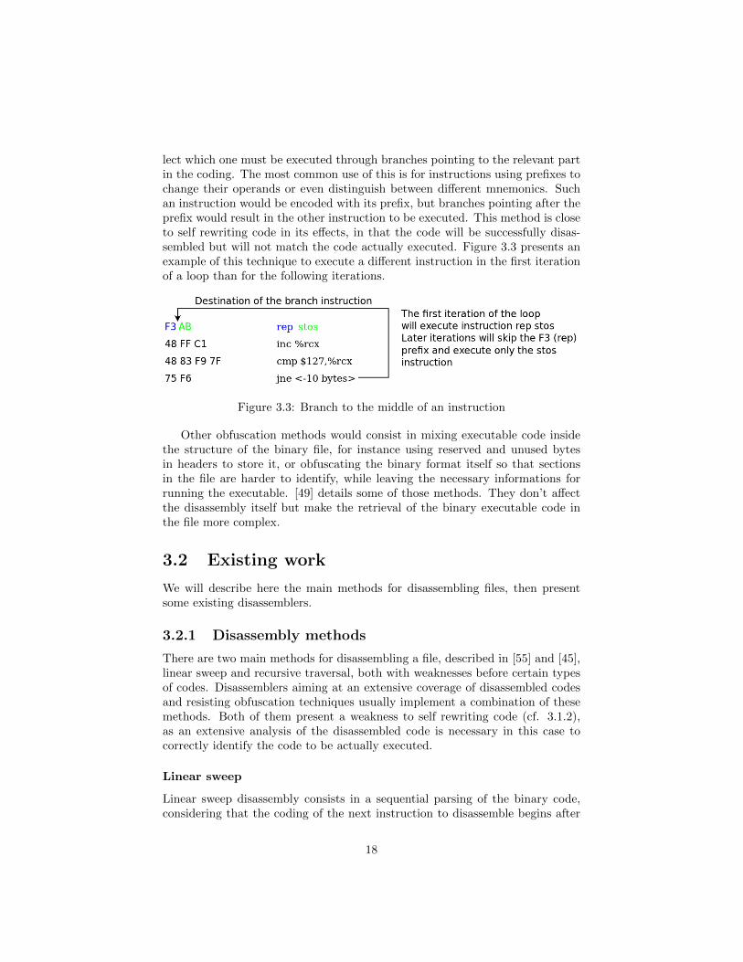
lect which one must be executed through branches pointing to the relevant partin the coding. The most common use of this is for instructions using prefixes tochange their operands or even distinguish between different mnemonics. Suchan instruction would be encoded with its prefix, but branches pointing after theprefix would result in the other instruction to be executed. This method is closeto self rewriting code in its effects, in that the code will be successfully disas-sembled but will not match the code actually executed. Figure 3.3 presents anexample of this technique to execute a different instruction in the first iterationof a loop than for the following iterations.
Figure 3.3: Branch to the middle of an instruction
Other obfuscation methods would consist in mixing executable code insidethe structure of the binary file, for instance using reserved and unused bytesin headers to store it, or obfuscating the binary format itself so that sectionsin the file are harder to identify, while leaving the necessary informations forrunning the executable. [49] details some of those methods. They don’t affectthe disassembly itself but make the retrieval of the binary executable code inthe file more complex.
3.2 Existing work
We will describe here the main methods for disassembling files, then presentsome existing disassemblers.
3.2.1 Disassembly methods
There are two main methods for disassembling a file, described in [55] and [45],linear sweep and recursive traversal, both with weaknesses before certain typesof codes. Disassemblers aiming at an extensive coverage of disassembled codesand resisting obfuscation techniques usually implement a combination of thesemethods. Both of them present a weakness to self rewriting code (cf. 3.1.2),as an extensive analysis of the disassembled code is necessary in this case tocorrectly identify the code to be actually executed.
Linear sweep
Linear sweep disassembly consists in a sequential parsing of the binary code,considering that the coding of the next instruction to disassemble begins after
18

Figure 3.4: Example of a linear sweep disassembly
the end of the previously disassembled instruction. Such a method ensures thatall the binary code that could be extracted from the file will have been parsed,but will be hampered by most of the challenges described in 3.1.
For instance, data mixed with code will throw a linear disassembler off courseand generate parsing errors or cause it to report erroneous instructions. Thismethod is also vulnerable to most obfuscation techniques, especially those in-volving the insertion of “junk” bytes.
Recursive traversal
Recursive traversal disassembly consists in the parsing of the binary code fol-lowing the control flow. A disassembler using this method will perform a linearsweep of the code until a branch instruction is encountered, at which point itwill attempt to resume its parsing starting from the destination address of thebranch. Such a method allows to overcome the problems presented by datamixed with code representing instructions, but relies upon the successful iden-tification of the targets of instruction branches. This is especially challengingin the case of indirect branches (cf. 2.2.2), whose target is not immediatelydeducible from reading the assembly code, and requires an analysis of the pre-ceding instructions to be identified.
This method can also be more slower and complex to implement than a linearsweep, for instance to handle conditional branches, where the control flow canreach two different addresses. Some obfuscation techniques specifically targetthis weakness by using fake conditional branches, where only one destination isactually used in order to cause disassembly errors. They can also change thereturn address of a call instruction; such an instruction is used to invoke a
19

Figure 3.5: Example of a recursive traversal disassembly
function and it is normally assumed that the execution will be resumed at theinstruction following it when returning from the function.
3.2.2 Existing disassemblers
Disassemblers are commonly used either as standalone tools to print the disas-sembled contents of a file, or as part of a more complex application to retrievethe assembly code contained in a binary file before further analysis.
Disassemblers using linear sweep
objdump objdump [26] is a standalone disassembler included in most Linuxdistributions, handling the architectures supported by this operating systemdepending on its build. It allows to disassemble executable, relocatable or sharedELF files (cf. 2.1.7) or a.out files (cf. 2.1.7) and print the assembly codethey contain. objdump uses an ELF parser to retrieve the location of theexecutable code inside the file and the labels, so as to print them with the codeat the address with which they are associated. It is also able to retrieve debuginformations in the file.
As a plain linear disassembler, objdump does not feature a mechanism fordetecting data mixed with code and simply flags any parsing errors.
Others standalone disassemblers ndisasm [25], udis86 [57] and distorm[36] are disassemblers for the x86 architecture. They don’t include a parser forthe binary file containing the code to disassemble and must be fed with the
20

appropriate boundaries. udis86 and distorm offer to access the disassembledinstructions through an API in addition to printing them.
Debuggers Debuggers usually implement a disassembly feature allowing ad-vanced users to view the assembly code being executed.
The GNU debugger gdb [16], offers to disassemble any range of addressesfrom the executable being debugged. The disassembler may report erroneousinstructions if the given starting address is not located at the beginning ofan instruction. It is also possible to disassemble whole functions provided thedebugging informations are present for them.
Disassemblers using other methods
The following disassemblers use an improved algorithm over linear disassembly,usually recursive traversal, occasionally complemented with linear sweep, inorder to extend their coverage.
PEBIL PEBIL (PMaCs Efficient Binary Instrumentation Toolkit for Linux)[44] is a tool used to instrument ELF executables compiled for the x86 ar-chitecture. Its first task when instrumenting an executable is attempting todisassemble it, flagging functions whose disassembly failed as ineligible for in-strumentation.
PEBIL uses the file’s symbol table to identify functions in the file, thenprocesses each of them using a control-driven (recursive) disassembly. If thisdisassembly fails, PEBIL falls back to standard linear disassembly, flagging thefunction as incompletely disassembled if this disassembly also fails. A disas-sembly failure can be due to an unrecognised opcode or to the discovery of abranch instruction pointing in the middle of an already disassembled instructionor outside the current function while not being a call instruction.
This last behaviour can lead to discard valid functions, as some compilers,like the Intel compiler icc, may add functions invoking one another using suchbranches. This happens especially when compiling files for use with OpenMP.
PLTO PLTO [56] is a tool allowing to instrument and optimise executablefiles for the x86 architecture without recompilation. PLTO uses a linear sweepalgorithm to disassemble a file. It then correlates the results with a check onthe target addresses of branch instructions. If a branch or relocation is foundto point to the middle of an already disassembled instruction, that instructionis marked as invalid, and the disassembly is resumed from the target.
This behaviour may cause an instruction to be incorrectly flagged as invalidfor codes where instructions with overlapping coding are used as described in3.1.2.
PLTO also attempts to analyse jump tables to identify the destination ofindirect branches.
21

UBQT UBQT (University of Queensland Binary Translation) [34] is a binarytranslation tool allowing to convert a binary executable from one architectureto another. The first step of the translation processes is the disassembly of thebinary into an internal representation. The decoding module uses a recursivetraversal algorithm. It sequentially disassembles instructions until a flow branchis met, at which point it resumes disassembly from one of the possible nextaddresses for the continuation of the flow, storing the other possible addressesin a queue for processing. The addresses of indirect branches are recovered withan pattern recognition algorithm to identify the location of jump tables.
An additional algorithm disassembles the parts in the code that have notbeen disassembled because they were not reached by any branch, discardingthose areas that are found to contain illegal instructions. The boundaries ofall disassembled areas are also checked against instructions performing registerupdates to see if they appear as operands, in order to resolve simple indirectbranches.
3.3 Solutions for disassembling
Our solution relies on MINJAG [58] to generate the architecture specific codeused for parsing instructions. A standard parser for the binary file format is usedto extract the binary code to disassemble and the labels. The debug informationsare retrieved as well if they are present using the appropriate parser for theirformat. Each section potentially containing code is then parsed and structuresrepresenting the assembly instructions are built.
Since the MADRAS disassembler is chiefly intended to be used by other toolsfor further analysis or before an operation by the MADRAS patcher, the mainconcern was ensuring good performances. Therefore, a linear sweep algorithmwas chosen to perform the disassembly. Instructions are parsed sequentially; ifa parsing error is detected, the instruction is flagged as bad and the parsingresumes at the next byte.
Labels retrieved from the binary file are stored in separate structures andlinked to the instructions found at the address to which they are associated.The disassembler attempts to identify the instructions targeted by direct branchinstructions and stores them in the representation of the instructions.
The detailed algorithm of the MADRAS disassembler is described in AnnexB.
3.3.1 Sanity checks
A certain number of sanity checks and metrics have been added to the disas-sembly process in order to detect potential parsing errors and fix the simplestones.
Some labels can be identified in binary files as marking the beginning of afunction. If the address associated to such a label is found to be in the middle
22

of a disassembled instruction, this instruction is considered as erroneous. It isthen marked as bad, and the parsing is resumed at the address of the label.
The disassembler also offers a simple metric for detecting potential areas ofdata mixed with code. A counter is increased for each consecutive error returnedby the parser and decreased after an instruction is successfully parsed. Thisallows to detect instructions correctly parsed but mixed with disassembly errors,which could therefore correspond to data bytes that matched with the coding ofregular instructions. This would allow to establish heuristics for discarding someof these instructions, possibly requesting another pass of the disassembler forsome instructions to recover actual code that was badly disassembled becauseof its proximity to the boundaries of the data section.
The disassembler offers another information about the flow. When scanningthe disassembled instructions for associating direct branches to the instructionsthey branch to, unconditional branches or return from subroutine instructionsare detected. All instructions following such an instruction are then flagged untilthe first instruction identified as the destination of a direct branch is met. Thiswill in effect flag all instructions that can’t be reached from a direct branch.It will help to allow identifying instructions that are potentially disassemblyerrors, instructions that are the target of an indirect branch, or dead code usedfor instance for padding added after the end of a function.
3.3.2 Limitations
The MADRAS disassembler does not handle macro instructions and will alwaysreturn the corresponding instructions instead of the macro mnemonic standingfor them.
3.4 Applications
The MADRAS disassembler is functional and currently supports the x86-64 andk1om instruction sets, for the binary files using the ELF format with the optionalDWARF debug informations. It is available as a standalone disassembler andfully integrated into the MAQAO framework [31]. MAQAO is a static analysistool allowing to analyse binaries and build their control flow and data depen-dency graphs. It relies on the MADRAS disassembler to decode the assemblyinstructions contained in the binary and provide their representation. The staticanalysis plug-in for MAQAO uses additional informations added by MADRASafter parsing of the instructions to build estimates of the cycles needed for theexecution of loops or functions.
The MADRAS disassembler is also the entry point for the MADRAS patcher,which is also used by the MAQAO framework to instrument files.
23
3.4.1 Performances
The MADRAS disassembler was tested for coverage on binary files containingextensive combinations of instructions for the supported architectures, using theassembly sources of the files as reference. The disassembly errors amounted toless than 0.2% for the x86-64 architecture and less than 0.01% for the k1omarchitecture. Most of the errors for x86-64 are due to composite instructions,which MADRAS can’t handle (see 3.3.2).
The speed of the MADRAS disassembler was compared against objdump,whose architecture specific code is hard coded instead of being generated. Inits standard mode of operations, MADRAS disassembly speed is on average40% slower than objdump, but in this mode the disassembler builds internalstructures representing instructions before printing them. In a special mode ofoperations where instructions are printed as they are found in the file and nostructure is allocated, MADRAS is only 10% to 20% slower than objdump.
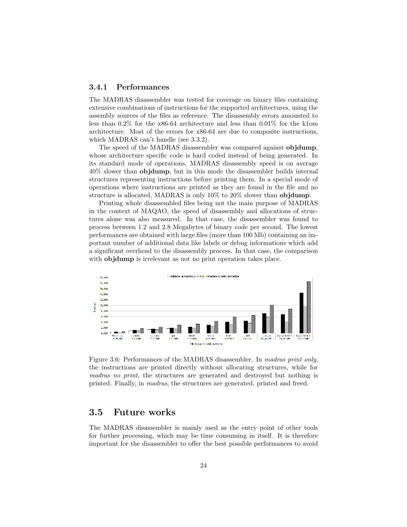
Printing whole disassembled files being not the main purpose of MADRASin the context of MAQAO, the speed of disassembly and allocations of struc-tures alone was also measured. In that case, the disassembler was found toprocess between 1.2 and 2.8 Megabytes of binary code per second. The lowestperformances are obtained with large files (more than 100 Mb) containing an im-portant number of additional data like labels or debug informations which adda significant overhead to the disassembly process. In that case, the comparisonwith objdump is irrelevant as not no print operation takes place.
Figure 3.6: Performances of the MADRAS disassembler. In madras print only,the instructions are printed directly without allocating structures, while formadras no print, the structures are generated and destroyed but nothing isprinted. Finally, in madras, the structures are generated, printed and freed.
3.5 Future works
The MADRAS disassembler is mainly used as the entry point of other toolsfor further processing, which may be time consuming in itself. It is thereforeimportant for the disassembler to offer the best possible performances to avoid
24

being a bottleneck in the processing as a whole. One of the main goals of theworks on the disassembler is the continuing increase of performances. This mustnot however be done at the expense of the agnostic approach to the architectureallowed by generating the code with MINJAG. Conversely, the implementationof the other evolutions presented here must not be at the expense of a loss ofperformances.
Since MADRAS was designed to support multiple architectures, it will be in-teresting to add support of more of them. While most of the architecture specificcode will be handled by MINJAG, this may lead to some updates in MADRASto handle some specific mechanisms of some architectures, for instance the wayinstructions are bundled in IA64.
In the same order of idea, the support of other binary file formats, likeMach-O or PE, could allow the MADRAS disassembler to process files fromother systems as Linux.
Another upcoming work will be fixing the current limitation on MADRASconcerning the handling of macro and composed instructions. This will re-quire updates in the parser and possibly in MINJAG as well, as the parserand disassembler currently operate on a per-instruction basis. Handling thoseinstructions will require an additional processing at a higher level.
Since the MADRAS disassembler aims at providing most of the available in-formations from the binary file, another interesting lead would be the retrievalof informations from the data sections, especially in the identification of indi-vidual variables. The bytes in the data sections of the code are not separateddepending on the variable which they represent and there is no easy way toidentify them from their values, for instance with a parsing similar to the pro-cess used for disassembly. It is however possible to use some of the informationspresent in the file to extrapolate the location of some of the variables in thedata sections.
First, compilers may add labels in the binary file associated to addresseslocated in the data section. This may be a strong hint that these addressescorresponds to the first byte of the data contained in a variable. Second, ifmultiple instructions are found to reference a given address in the data section,it is likely that this address also corresponds to the first byte of a variable. Thislast information is less reliable, as accessed addresses could actually representvarious cells in a single array, and a heuristic would need to be defined to refinethis analysis, possibly combining it with the results from the first method usinglabels.
These analyses could also be useful in identifying areas of data embeddedwith the code.
Finally, in order to ensure a better accuracy on the disassembled code anddetect more of the cases of code embedded with data, some elements of recursivedisassembly could be added, while avoiding to add too much of an overhead.
25

Chapter 4
Binary Rewriting
Patching a file consists in the modification of an already compiled executablewithout recompiling it. Since it amounts to modifying the binary code of thefile it can also be identified as binary rewriting.
The most common patching operations are the insertion of a call to a functionor of a snippet of assembly code allowing to retrieve informations at run timein order to perform timing or data profiling. Other operations would aim atmodifying instructions in the file to check their effect on the overall performanceof the application.
A possible way to perform binary rewriting would be to analyse the filein order to rebuild the intermediary representation used by the compiler fromthe binary code, then modify it to apply the needed patching operation andreassemble it. However, decompilation is a complex problem that may notalways have a reliable solution, and, since the purpose of patching is usuallyto retrieve informations about the behaviour of the compiled file, this intrusivemode of patching could extensively change the structure of the generated code,like source patching would, and invalidate the result of patching.
We will focus here on patching methods involving a direct rewriting of thefile. The main challenge comes from the fact that, unlike object files, executablesare not meant to be modified, and some can even contain specific countermea-sures to prevent this. For instance, an executable may contain multiple fixedreferences that could prove complex to identify for updating.
The patching of a binary file involves the following steps:
1. Retrieving the code present in the file
2. Alter the assembly code as needed by the patching operation
3. Rebuild the file as a valid executable
Step 1. was covered in chapter 3. We will focus here on the challenges andsolutions to steps 2. and 3.
The term “patch” will be used here for any operation modifying a binaryexecutable, while “instrumentation” is reserved for the specific modifications
26

aiming at retrieving informations from the executable at runtime, like dataprofiling, memory tracing, or timing. Thus, instrumenting a code is done bypatching it, but not all patching operations aim at instrumenting a file.
We will first explore the challenges of patching (section 4.1), then commonsolutions and some existing implementations (section 4.2). We will then presentour choices and their implementations (sections 4.3 and 4.4), and then theirfuture evolutions (section 4.5).
4.1 Challenges of binary rewriting
Unless the patching requires specific needs, a patched file must have the samebehaviour as the original. For instance, its output is usually expected to be thesame for a given input. Most importantly, the patched program must not crashwhen run with standard parameters.
This means the control flow and the data flow must be kept intact, or asclose as possible to the original, and that the patching operation must not causethe appearance of forbidden or undefined operations.
A prerequisite for correct patching is the successful disassembly of the file,or at least the part concerned with patching. We are assuming here that thefile was correctly disassembled.
4.1.1 Control flow
When running an executable file, the processor uses the instruction pointer toidentify the address of the instruction to execute. The binary code present atthis address is decoded, then the instruction pointer is updated to contain theaddress corresponding to the end of the decoded instruction. If the instruction isa branch instruction, its execution will update the instruction pointer to containthe address pointed to by the branch.
If the instruction pointer happens to contain an invalid address, the programexecution will fail. If the address is located outside the segment allocated tothe program for execution, this will cause a segmentation fault. If the addressdoes not contain binary code that can be decoded into a valid instruction, anunknown opcode exception will be thrown by the processor; this will happen forinstance if the instruction pointer references an address inside a valid instruction.If the code pointed to by the pointer still happens to be successfully decodedinto an instruction, the processor will have lost synchronisation with the actualcode and may eventually encounter a binary code that can’t be successfullydecoded.
If the instruction pointer contains a valid address, but the code at this ad-dress is not meant to be executed at this point, the program’s behaviour will dif-fer from the original, ranging from returning incorrect results to a segmentationfault, for instance if the code attempts to access a memory address containedin a register that happens to be set to a null value. This case can also happen
27
if the instruction pointer was incorrectly set to contain an address set in themiddle of an instruction but still could disassemble it as a valid instruction.
It is thus necessary to ensure that branches in a patched file still point tovalid instructions, and that those instructions are coherent in regard of theoriginal control flow of the program. This concerns direct as well as indirectbranches (see section 2.2.2 for the description of those branches). For this it isnecessary to be able to identify the destination of those branches.
While the destination of a direct branch can be easily identified statically,it is not always possible for indirect branches, and those may require advancedanalysis to identify their destinations. In particular, while direct branches haveone possible destination, indirect branches are mainly used when the destinationcan vary depending on runtime data. It may be therefore necessary to identifyall possible values that the branch operand could take to be able to updatethem.
In some cases, the value stored in the operand used by an indirect branchcan be the result of a series of calculations, some of them possibly conditional.Identifying those values may be complex statically, since the number of possiblepaths can increase exponentially when attempting to trace the origin of a value.
Indirect branches can also use a switch table, where the branch operandreferences a cell in an array containing the address to branch to. This arrayis usually stored in the data section, and as such its boundaries can be hardto identify. For instance, the cell can be identified by a complex calculation,making even the base of the array hard to identify. The array can also becontiguous to other such arrays, making the analysis of its contents inconclusivein order to identify its boundaries.
Finally, addresses can appear as immediate values in assembly code. Thisis the case for instance when passing an address of a function as parameter toanother function. It is impossible to differentiate such an address from anotherimmediate without some heuristics.
If the patching changes the size of code, which is the case most of the timeif probes need to be inserted, the addresses will have to be updated. For thereasons stated above, it may not be not possible to successfully identify all ofthem. In the case of indirect branches whose target is the result of a non-trivialcalculation, updating them may also be complex and lead to further modificationof the code.
The behaviour of the executable also depends on its data accesses and sothe patcher must keep their coherence.
Some architectures allow to reference memory locations based on the addressof the instruction referencing them. Those instructions must be updated if theinstruction is moved or if the offset to the memory location changes. This isthe case if code is added or removed between the instruction and the memoryaddress it references.
28

4.1.2 Saving the context
The execution of a program also depends on the runtime environment: valuesstored in registers, on the stack, or in other memory locations. When a patchingoperations adds code to a file, this code is liable to change this environment.Since this code may not be known during the patching operation, for instanceif it is located in a dynamic library, it is not possible to identify which elementsof the environment it will impact.
Registers are used to store values used by instructions. The conventions ofthe relevant architecture binary interface specify which of those registers (alsocalled scratch registers) must be saved before invoking a function. It is assumedthose registers can be used by a function without saving, as the compiler addedthe instructions for saving them before invoking the function. However, whenpatching a code, a function call may be inserted anywhere, making the additionof the instructions for saving those registers necessary during the patching op-eration. In some cases, the process of invoking an external function may alsooverwrite some registers. Finally, it has been observed that, for executablesbuilt from a single file, the compiler may not have obeyed the architecture con-ventions regarding the passing of parameters when invoking internal functions,for optimisation purposes.
The stack is an area of memory used for storing local data and passingparameters to invoked functions, depending on the architecture and the levelof compilation optimisation. Its top level is usually identified by the stackpointer, but the code of a function may actually access any location inside thestack regardless of the position of the stack pointer. A detailed analysis of thecode is necessary to identify the parts of the stack that are used, otherwise thecode added by a patching operation may modify the values on the stack. [47]references the problems linked with the saving of the stack.
For instance, an inserted function call will modify the stack, first when savingthe calling context, then possibly when passing parameters to the function, andfinally by the called function itself. If the code where the function call wasinserted was using data stored on the stack, the inserted code may overwritedata used by the executable and cause errors.
It is therefore necessary to save data stored in registers and flag registersbefore inserting code. If the patched code uses the stack, it must then be movedbefore the inserted code is executed. This will usually be done by adding assem-bly instructions before the inserted code performing the operations necessary forsaving all other informations and after those restoring them after the executionof the inserted code.
Some architectures may also assume that the stack pointer is aligned at thebeginning of a function. If a function call is inserted in the middle of a func-tion, the stack pointer may not be aligned at this point, making an alignmentnecessary to ensure the called function works properly.
29

4.1.3 Inserting functions
For easier implementation, instrumentation or profiling is usually done by in-serting calls to ad hoc functions that have been already developed and compiledseparately, the alternative being the insertion of the corresponding assemblycode, which could be complex depending on the instrumenting function.
If the format of the binary file to be patched allows it, those functions canbe referenced in a shared library, and the patcher must insert the requiredinstructions for invoking such a function. This usually implies the edition of therelevant relocation table stored in the binary file, and adding the appropriatearchitecture specific snippet of code.
In other cases, it may be necessary to add the whole body of the function tothe file. This can be the case for instance if the patched executable is supposed tobe standalone and not requiring any external libraries. In that case, the patcherneeds to ensure that all required functions are added to the file, including thoseneeded by the instrumentation function or its dependencies.
4.2 Existing work on patchers
We will first present here alternatives to binary rewriting for instrumenting filesas well as some methods commonly used, then other tools offering to patch orinstrument files.
4.2.1 Code displacement
One of the most widespread methods for addressing the problems tied to thepreservation of the control flow when patching a program is code displacement,also called code relocation. It consists in branching the control flow to an addedarea of code. Instructions in the original code are modified to add a branchinstruction. The branch points to this new area of code which contains thedisplaced code and any modification requested by the patching operation. Theflow is then branched back to the original code.
An alternative is the use of system interrupts instead of branches to jumpto the displaced code. This presents the advantage that the interrupt operationtakes care of saving the context and transferring the control to the area ofrelocated code. In the case of x86, it presents the additional interest of beingaccomplished with a one byte instruction, the shortest length, thus ensuringminimal alteration of the original code to insert it, since other branches arealways longer. The main drawback of this method is the important overheadbrought by the interrupt operation for saving the context and transferring thecontrols.
This method can be applied either for binary rewriting or dynamic patching.[43] describes this method, which was implemented for the qp and qpt in-
strumenters for the MIPS and SPARC processors.
30

4.2.2 Compiler-based instrumentation
One method of performing instrumentation is through the compiler. The codemodifications are performed during the compilation process, so that the com-piled executable contains all required alterations. This allows to benefit from thecompiler’s internal representation of the code to ensure that the modificationswill not damage the control flow of the generated executable, while preventingthe transformations performed by the compiler on the code to be impacted bythe modifications, which is the main drawback from source instrumentation.
This is the method used by the GNU profiler gprof [39, 17, 59] to add probesduring processing by the gcc compiler. Another use of this is described in [60],where executables for the MIPS processor are instrumented using additionalinformation provided by the linker to create relocation tables allowing to updateall branches inside the code, while branches to data section are not updated asthe executable files contain a gap in addresses between the code and data wherethe inserted code will be added, thus avoiding the need to move the data section.
The main drawback of this method is that it implies being able to modifythe code of the compiler used, which may not be possible if the compiler usedin the files to be analysed is not Open Source. It can also lead to an increasedimplementation workload if multiple compilers must be supported, as each ofthem would have to be patched accordingly. It also requires access to the ap-plication sources in order to recompile it with the appropriate options, which isnot always possible. Finally, while such methods allows to relatively easily in-strument files on a function or loop level, it may be more complicated to specifyfine grained modifications, such as at an instruction level.
4.2.3 Dynamic patching
Dynamic patching consists in the modification of a file during its execution,either by using a supervising thread or by altering the executable after it is hasbeen loaded into memory.
Thread supervision
The use of a supervising thread, such as the one allowed under Linux by thesystem call ptrace [40], allows to control the execution of another thread andchange its runtime data context. Debuggers are a common application of thismethod. It can be used in order to perform instrumentation in a file whileavoiding problems tied to the preservation of the control flow and the dataenvironment, since all runtime variables can be accessed.
One drawback of this method is that the process of patching the file willhave to be repeated for every execution of the application, adding its overheadto all of them. It also requires an additional thread to be executed, whichmay not be possible or require additional configuration from the environment,for instance in the case of an already multi-threaded code. Finally, the wholecode may not be accessible through this method, preventing some of the more
31

detailed analysis of the executable before settling on the patching operations toperform.
Patching in memory
Patching the representation of the file in memory allows to access the code afterit has been loaded and all operations like relocations have been performed. Italso allows to perform multiple patching operations during the execution of thefile, such as removing or disabling a given modification in a loop after a certainnumber of iterations.
It suffers from the same drawback as the thread supervision method in thatthe overhead of the patching process will be added to each execution of the file,while presenting the same challenges as static binary rewriting.
4.2.4 Simulation
Another method is simulating the execution of the application, or dynamicallytranslating it in a process similar to Just In Time compilation while performingthe required modifications. The main interest of this method is that, since thewhole executable is reinterpreted, it allows to avoid all problems tied to theconservation of the control flow or data context, as modifications brought bythe patch operations are integrated in the execution as if they had been presentat compilation without altering the overall structure of the program.
This is done however at the cost of an important overhead, since the trans-lation process can be time consuming. It can also present issues when handlingmulti-threaded applications, as it requires being able to emulate multiple threadsand their communications, which are handled at the system level.
4.2.5 Patching tools
We will present here some existing patching or instrumenting tools and the waythey address the challenges of binary rewriting.
DynInst
DynInst [33, 32] is a static and dynamic binary instrumenting tool. It allowsto insert instrumentation function calls at different points of the executable’sControl Flow Graph (CFG).
Instrumentation is done through code displacement using a double trampo-line. The original code is modified to replace one instruction with a branch toan inserted area of memory containing the replaced instruction, and a branchto a mini-trampoline. The mini-trampoline is another inserted area of codecontaining instructions for saving and restoring the context, passing argumentsto the inserted function and invoking it.
This behaviour is used for static as well as dynamic patching.
32

PEBIL
PEBIL [44] is a binary rewriting tool allowing to patch ELF files for the x86-64 architecture. PEBIL allows to insert function calls and assembly snippetsin binaries for instrumentation purposes. PEBIL addresses the problems ofpatching by performing code relocation at a function level. New code anddata segments are created to contain the added and modified code. When theassembly code in a function needs to be patched, the whole function is movedto the new code segment and its code is altered as needed by the patchingoperation.
Functions that could not be properly disassembled are flagged as being in-eligible for instrumentation, as well as functions too small to contain a branchinstruction, which can happen in x86-64. PEBIL also adds code around inser-tions for saving the registers and move the stack to save the context.
PIN
PIN [41] is a tool performing runtime instrumentation through thread supervi-sion, allowing to trace an executable during its execution and monitor variousparameters. It is available for Linux executables on x86 (both 32 and 64 bits),Itanium, and XScale architectures, and for Windows and MacOS on x86 archi-tectures.
The tool also allows to insert calls to functions during the execution of thecode, as well as modify the contents of memory during execution.
It is possible to insert probes in the code before execution, which redirectthe execution flow to another function in a process similar to code relocation.A file so instrumented with PIN can be run under GDB. This mode does notwork on multi-threaded applications and does not check if the destinations ofbranch instructions is valid.
Valgrind
Valgrind [51, 52] is an instrumentation platform for Linux executables underx86, ARM, PowerPC and MIPS architectures. It is a framework for buildingtools using its instrumenting abilities.
The core of Valgrind functions as a JIT compiler. It begins by disassemblingthe executable code and converting it into an intermediate RISC-like assemblylanguage. Instrumentation is done on this intermediate representation, whichis then recompiled into the assembly language of the target architecture andexecuted. The contents of the registers used by the architecture are stored inmemory.
System calls are handled by setting up the system state as if the original codewas still executing. Threads are handled by Valgrind, which executes them ona single thread that periodically switches between the simulated threads.
33

Other tools
PLTO PLTO [56] performs binary rewriting, and include optimisation as wellas instrumentation options. It is used for IA 32.
Elfsh/ERESI The Elfsh utility and libraries, later merged with ERESI [37](Reverse Engineering Software Interface), allows to disassemble, perform dy-namic and static analysis, and patch ELF executables. It is available for x86 32and 64 bits, and SPARC architectures.
Binary rewriting is done by inserting relocatable files into executables, andredirecting function calls to point to the inserted functions.
Etch Etch [54] is a binary rewriting tool for Windows x86 executables. It wasreleased in 1997 and has undergone few evolutions since.
Etch allows to add, modify or remove parts of the code of an executable inorder to perform instrumentation or optimisation.
4.3 Solutions for binary rewriting
Our solution relies on code displacement, as described in 4.2.1, to address thechallenges tied to static patching. It will be used for all modifications thatwould change the size of the code: insertion, deletion, or modification into aninstruction coded on less bytes than the original for architectures with variableinstruction length.
The main constraint of the code displacement method is being able to cor-rectly detect and update all branches or memory references to and from thedisplaced code. Since those are not always easily identifiable, the goal was toreduce the size of the displaced code as much as possible. This could be achievedby moving only a single instruction, and returning the flow to the instruction im-mediately following it; however in architectures with variable instruction length,a branch instruction could be larger than the instruction to be patched, mak-ing this simple replacement not possible. The solution was therefore to allowvarying scopes of displaced codes depending on the patched location.
We rely on a binary editor to parse the binary file for the format of the filebeing patched and rebuild the patched file. This is the same editor we use fordisassembling the file.
We also rely on an assembler whose architecture specific code was gener-ated by MINJAG [58] to generate the binary coding of modified or insertedinstructions.
We will first detail here our implementation of code displacement, then thevarious workarounds allowing to address the remaining problems, and the cur-rent limitations. We will also address the issues tied to the saving of context.
The detailed algorithm of the MADRAS patcher is described in Annex B.
34

4.3.1 Conventions
In most cases, a single patching modification will target a single address: itwill either consist in the insertion of a function call or code snippet at thisaddress, or the modification or deletion of the instruction at this address. Theonly exception would be the deletion or replacement of a series of consecutiveinstructions, but this can also be considered as a modification targeting theaddress of the first instruction in the series. In the remainder of this chapter,we will use the term “patched address” to identify such an address targeted bya patching modification. Since the patcher always targets the code, we will alsouse interchangeably the term “patched instruction” to identify the instructionlocated at the patched address.
4.3.2 Code displacement
The implementation of code displacement consists in the following steps:
1. Identification of the code to displace.
2. Replacing the displaced code with a branch instruction in the originalcode.
• If the branch is smaller than the displaced code, the remaining spaceis filled with padding to ensure the address of the first instructionfollowing the displaced code is unchanged.
3. The displaced code is modified according to the requested patched oper-ation.
• Any relative references to another part of the executable code or dataare also updated to reflect the change of addresses of the code
4. The new branch instruction is set to target the first instruction in themodified displaced code.
5. A branch instruction is appended to the displaced code, targeting the firstinstruction following the displaced code.
All displaced codes are appended to one another and grouped into a newsection. This section will be added to the patched file by the binary editor. Theeditor will be responsible for affecting an area of virtual addresses to this sectionthat is outside of the original range of virtual addresses of the file. Figure 4.1presents a schematic view of code displacement following this implementation.
The displaced code being in a new area, any modifications can be performedon it without any impact on the remaining of the code.
The crucial step is the identification of the displaced code. As noted above,it should be as limited as possible to avoid moving the destination or originof a branch instruction that could not be properly identified, while being largeenough to contain a branch instruction.
35

Figure 4.1: Code displacement
We support three different scopes for identifying the code to displace, eachof them leading to a greater or equal area of displaced code than the previousone. Depending on the options, the patcher will switch to the next scope if thecurrent does not return the necessary size, or stop and return a warning for thegiven patch operation.
We also devised a workaround using trampolines if the size is not largeenough to contain the branch instruction.
Displacing single instructions
This is the safest mode considering the preservation of the flow, as moving onlythe patched instruction ensures that all branches pointing to it, even those thatcould not be detected, will point to the inserted branch instruction instead.
If the patched instruction is smaller than the branch instruction, the patcherwill attempt to add other instructions to the displaced code until either thelength of a branch instruction is reached or a branch instruction or destinationof another branch instruction is met. It will first attempt to add the instruc-tions immediately following the patched instruction, then those immediatelypreceding it.
Displacing basic blocks
In this mode, the basic block containing the patched instruction will be dis-placed. Such a basic block is identified as follows:
• Begins either at:
36

– the first instruction before the patched instruction that is the desti-nation of a branch
– after the first branch instruction found before the patched instruction
• Ends either at:
– before the first instruction after the patched instruction that is thedestination of a branch
– the first branch instruction after the patched instruction
– the patched instruction if it is a branch instruction itself
• If the patched instruction is a branch, the block will also include all nopinstructions following it
This scope is the default mode, as it presents a good compromise betweenlimiting the size of displaced code and ensuring that it is large enough to containa branch instruction. Another advantage of this scope is that it reduces thenumber of added branches if more than one modification has to happen in thesame basic block, as it will be moved only once.
It is however possible to encounter basic blocks with the definition abovethat will be smaller than the smallest branch instruction. For instance, in x86,the instruction returning from a function, ret, is coded on 1 byte, while thesmallest branch instruction uses 2 bytes. Compilers can generate code where abranch instruction points to a ret instruction immediately followed by non nop
instructions, making it a 1 byte basic block.The main drawback of this method is its reliance on the correct detection of
branch instructions destinations.
Displacing functions
The last scope moves whole functions. Functions are identified in a simplis-tic manner as the instructions contained between the first label immediatelypreceding the patched address up to but not including the label immediatelyfollowing it.
The main advantage of this scope is that it ensures that the displaced codewill have the required size in most cases, although it is still possible for a verysimple function to be still smaller than a branch instruction.
It presents the drawback of increasing the size of displaced code, and thus thechances that some of the displaced instructions are targets of indirect brancheswhich could not be identified and will not be updated, thus potentially leadingto a break of control flow.
Trampolines
If the displaced code is smaller than the branch instruction, a workaround isimplemented if the architecture offers a smaller branch instruction for a smaller
37

offset. This is the case in x86-64, where a two bytes long branch instruction isdefined (cf. 2.2.3).
If the displaced code is large enough to contain such a smaller branch in-struction, this instruction will then used to displace the code using a trampoline.In this method, the patcher will attempt to find an area of code meeting thefollowing criteria:
• It is eligible for being displaced given the current scope
• It can be reached from the patched address with a small branch instruction
• It is at least as large as two largest branch instructions.
This area can be an area of code that was already displaced for another patchingoperation, if it was large enough to contain a large branch instruction in additionto the one used to branch to the displaced code.
If such an area is found, it will be moved using the standard method forcode displacement. In the space left, a large branch instruction, designated as a“trampoline branch”, is inserted. The area containing the patched instructionwill be moved normally to the section containing displaced code, and appendedwith a branch instruction pointing to the instruction immediately following it,as is the normal behaviour. The trampoline branch is set to point to thisdisplaced area. The space left by the area containing the patched instructionis replaced by a smaller branch instruction pointing to the trampoline branch.The principle is described in figure 4.2.
Figure 4.2: Principle of trampolines
While it would be possible to keep linking trampolines until an area suitableto contain a large branch instruction is found, this behaviour is currently notimplemented, as it could lead to a “domino effect” where large portions end upbeing displaced.
38

4.4 Applications
The MADRAS patcher is functional and currently supports the x86-64 andk1om instruction sets, for the binary files using the ELF format. It is accessiblethrough a low-level API described in A.
4.4.1 Customisable behaviour
The MADRAS patcher is a low level tool, allowing for a fine granularity whilekeeping its use relatively simple. Most of its behaviour can be controlled throughtoggles either for a whole patching session or for separate patching operations.
Scope selection
It is possible to chose which kind of scope to use when defining the area ofdisplaced code around the patched instruction, and whether the patcher canswitch to a broader scope if the current one could not find an appropriate area.Likewise, the use of trampolines can be disabled.
Branches updating
The MADRAS patcher also allows to selectively update the branches to patchedinstructions when the patch aims at inserting code. The normal behaviour wheninserting code before the patched instruction is that all branch instructionspointing to it are updated to point at the inserted code, thus ensuring that itwill always be executed before the patched instruction. It is possible to requestthat only some branches will be updated that way while leaving the others topoint to the patched instruction. This can be useful for instance if the insertedcode aims at profiling the entry point of a loop or function, but should not beexecuted when this point is accessed from inside the loop or function.
Forcing displacement
In the current version, the default behaviour if a displacement can not be done isto skip it and print an error message. It is possible to to bypass this behaviourand force the displacement anyway. This can be useful when all the blocksadjacent to the one causing the error will also be displaced, thus solving thelack of space problem. Usually however, forcing the displacement will lead thepatched file to crash or behave incorrectly.
Saving the context
When the patching operation consists in the insertion of a function call, theMADRAS patcher automatically encloses the insertion with instructions forsaving the register and execution flags context and restoring it afterwards, aswell as aligning the stack. It is possible to prevent the patcher from addingthese instructions, allowing the application using MADRAS to fine tune the
39

registers to save based on the knowledge of the inserted functions for betterperformances.
Conditional executions
The MADRAS patcher also offers to set conditions on the execution of an in-serted function or assembly code snippet. These conditions are compiled intoassembly instructions that are added to the inserted code and ensure it will beexecuted only if the conditions are met. This allows for instance to execute aninserted code only for some iterations of a loop, or for more complex uses insertdifferent codes to execute depending on the possible values of an operand usedby an indirect branch.
4.4.2 Limitations
The current version of the MADRAS patcher assumes that the added sectioncontaining displaced code is reachable from the original code with a directbranch instruction. In x86-64, such instructions encode their offsets on 32 bits,allowing for an absolute offset of 2 Gigabytes. If the section containing dis-placed code was added at an address more than 2 Gb apart from the originalcode, this instruction will not be usable to branch to and from this section.Such an offset may occur for instance if the displaced code was to be addedafter the section containing uninitialised data, which can reach such a size forsome executables. In such a case, the patcher would need to use an indirectbranch or use a trampoline.
Another limitation is that the patcher does not update indirect branch in-structions when they are moved. This is not a problem in the x86-64 or k1om ar-chitecture, as in those all indirect branches contain absolute addresses, but needsto be addressed when using MADRAS on architectures where these branchescan contain relative addresses.
4.4.3 Use in MAQAO
MADRAS is fully integrated into the MAQAO framework [31]. The patcherallows MAQAO to complement its static analysis with instrumentation throughits instrumentation language MIL.
MIL offers a simplified interface for instrumenting files, inserting functioncalls or assembly code at various points in the Control Flow Graph.
–TODO– Add the graphs from the MIL paper
4.4.4 Use by DECAN
DECAN [42] is a tool allowing to remove selected instructions accessing memoryfrom executables in order to identify their impact on the overall performances.DECAN relies on the MADRAS API to generate the modified executables.Among the transformations performed by DECAN are:
40

• Removing some or all load and/or stores instructions from a given loop orreplacing them with nop instructions
• Replacing the memory address operands in instructions with a fixed mem-ory address
• Replacing instructions storing a value into memory with instructions load-ing a value from memory, and reciprocally.
DECAN also inserts assembly code for timing the transformed loops. It canalso perform these transformations on a single iteration of a given loop.
4.5 Future works
Since MADRAS was designed to support multiple architectures, one of the mostimportant upcoming evolutions of the patcher will be the support of more ofthem. While the general behaviour of the patcher has been designed to not bedependent on the architecture, the support of new architectures may require theaddition of further mechanisms to ensure an optimal coverage of the availablecodes.
Another useful evolution would be the support of other binary formats, al-lowing the MADRAS patcher to process files for the Windows or OSX operatingsystems. This will require being able to successfully rewrite files for those for-mats, including the handling of their loading instructions and the procedures toinvoke external functions.
Other evolutions are tied to the evolutions of the disassembler, especiallyas far as the detection of jump tables are concerned. Being able to identifymore precisely the tables used by indirect branches would allow to update themwhen the addresses they contain correspond to instructions moved by the patchoperations.
Another evolution includes getting rid of the limitation concerning the useof large branches mentioned in 4.4.2 in order to handle files with large data oreven code sections.
Finally, since the MADRAS patcher is designed to be part of a tool chainincluding disassembler and analysis modules, and is intended to be used oncomplex or large files where disassembling or analysis could be time consuming,accessing the best performances for the patching operations would prevent itto become a bottleneck. Evolutions aiming at improving the patching speed ofMADRAS are therefore equally important.
41

Chapter 5
Conclusion
We presented MADRAS, a tool allowing to disassemble and patch binary exe-cutables and libraries. MADRAS is functional and supports ELF files for thex86-64 and k1om architectures.
MADRAS is part of the MAQAO analysis framework and is an essentialpart of its life cycle. The disassembler is the entry point of all static analyses,while the patcher is used by the MIL and DECAN modules to perform allinstrumentations or other transformations.
The multi architectural nature of MADRAS, provided by MINJAG, ensuresthat MAQAO can be easily adapted to support new architectures with minimalimplementation effort.
The MADRAS disassembler aims at offering a good compromise betweenspeed and precision, while providing helpful hints to the analysis tools using itsoutput.
The MADRAS patcher offers a low-level interface allowing a fine grainedcontrol of its actions, while being able to handle most cases in its default be-haviour.
As part of an evolving tool, MADRAS is due for more improvements, firststemming from exploiting its ability to support multiple architectures. Otherupdates will concern the MADRAS disassembler performances in speed andprecision, which could in turn affect the coverage of the patcher.
42

Bibliography
[1] AMD64 Architecture Programmers Manual Volume 1: Application Pro-gramming.
[2] AMD64 Architecture Programmers Manual Volume 2: System Program-ming.
[3] AMD64 Architecture Programmers Manual Volume 3: General Purposeand System Instructions.
[4] AMD64 Architecture Programmers Manual Volume 4: 128-bit and 256 bitmedia instructions.
[5] AMD64 Architecture Programmers Manual Volume 5: 64-Bit Media andx87 Floating-Point Instructions.
[6] a.out – assembler and link editor output.
[7] ARM Architecture Reference Manual.
[8] Arm software development toolkit.
[9] ARM R©Architecture Reference Manual ARMv7-A and ARMv7-R edition.
[10] ARM R©v7-M Architecture Reference Manual.
[11] ARMv6-M Architecture Reference Manual.
[12] ARMv8 Instruction Set Overview.
[13] Common object file format.
[14] The dwarf debugging standard.
[15] Executable and linkable format (ELF).
[16] Gdb: The gnu project debugger. In The GDB developers. Free SoftwareFoundation, Inc.
[17] Gnu gprof. In GNU Binary Utilities. Free Software Foundation, Inc.
43

[18] Intel R©64 and IA-32 Architectures Software Developer’s Manual CombinedVolumes 2A, 2B, and 2C: Instruction Set Reference, A-Z.
[19] Intel R©64 and IA-32 Architectures Software Developer’s Manual CombinedVolumes 3A, 3B, and 3C: System Programming Guide, Parts 1 and 2.
[20] Intel R©64 and IA-32 Architectures Software Developer’s Manual Volume 1:Basic Architecture.
[21] Intel R©Itanium R©Architecture Software Developer’s Manual.
[22] Intel R©Xeon Phi Coprocessor Instruction Set Architecture Reference Man-ual.
[23] Intel R©Xeon Phi Coprocessor System Software Developers Guide.
[24] Microsoft portable executable and common object file format specification.
[25] Ndisasm. In NASM Documentation. The NASM team.
[26] Objdump. In GNU Binary Utilities. Free Software Foundation, Inc.
[27] Os x abi mach-o file format reference.
[28] Power ISA Version 2.06 Revision B.
[29] Xcoff object file format.
[30] M. Accetta, R. Baron, W. Bolosky, D. Golub, R. Rashid, A. Tevanian, andM. Young. Mach: A new kernel foundation for unix development. pages93–112, 1986.
[31] D. Barthou, A. Charif Rubial, W. Jalby, S. Koliaı, and C. Valensi. Perfor-mance tuning of x86 openmp codes with maqao. In M. S. Muller, M. M.Resch, A. Schulz, and W. E. Nagel, editors, Tools for High PerformanceComputing 2009, pages 95–113. Springer Berlin Heidelberg, 2010.
[32] A. R. Bernat and B. P. Miller. Anywhere, any-time binary instrumenta-tion. In Proceedings of the 10th ACM SIGPLAN-SIGSOFT workshop onProgram analysis for software tools, PASTE ’11, pages 9–16, New York,NY, USA, 2011. ACM.
[33] B. Buck and J. K. Hollingsworth. An api for runtime code patching. The In-ternational Journal of High Performance Computing Applications, 14:317–329, 2000.
[34] C. Cifuentes, C. Cifuentes, M. V. Emmerik, M. V. Emmerik, N. Ramsey,N. Ramsey, B. Lewis, and B. Lewis. A retargetable static binary translationframework. Technical report, 2002.
[35] C. Cifuentes and M. V. Emmerik. Recovery of jump table case statementsfrom binary code. In Science of Computer Programming, pages 2–3, 1999.
44

[36] G. Dabah. Distorm.
[37] A. Desnos, S. Roy, and J. Vanegue. Eresi : une plate-forme d’analysebinaire au niveau noyau, 2008.
[38] A. Fog. Calling conventions for different c++ compilers and operatingsystems, 2008.
[39] S. L. Graham, P. B. Kessler, and M. K. McKusick. gprof: a call graphexecution profiler, 1982.
[40] M. Kerrisk. Ptrace(2), 2013.
[41] C. keung Luk, R. Cohn, R. Muth, H. Patil, A. Klauser, G. Lowney, S. Wal-lace, V. Janapa, and R. K. Hazelwood. Pin: building customized programanalysis tools with dynamic instrumentation. In In PLDI 05: Proceedingsof the 2005 ACM SIGPLAN conference on Programming language designand implementation, pages 190–200. ACM Press, 2005.
[42] S. Koliaı, Z. Bendifallah, M. Tribalat, C. Valensi, J.-T. Acquaviva, andW. Jalby. Quantifying performance bottleneck cost through differentialanalysis, 2013.
[43] J. R. Larus and T. Ball. Rewriting executable files to measure programbehavior. SOFTWARE PRACTICE & EXPERIENCE, 24:197–218, 1994.
[44] M. A. Laurenzano, M. M. Tikir, L. Carrington, and A. Snavely. Pebil:Efficient static binary instrumentation for linux.
[45] S. Li. A survey on tools for binary code analysis, 2004.
[46] C. Linn and S. Debray. Obfuscation of executable code to improve re-sistance to static disassembly. In IN ACM CONFERENCE ON COM-PUTER AND COMMUNICATIONS SECURITY (CCS, pages 290–299.ACM Press, 2003.
[47] C. Linn, S. Debray, G. Andrews, and B. Schwarz. Stack analysis of x86executables.
[48] H. Lu. Elf: From the programmer’s perspective. NYNEX Science & Tech-nology Inc, page 95, 1995.
[49] B. P. Miller and K. A. Roundy. Binary-code obfuscations in prevalentpacker tools. ACM Computing Surveys, June 2012.
[50] B. P. M. Nathan E. Rosenblum, X. (Jerry) Zhu and K. Hunt. Learning toanalyze binary computer code, 2008.
[51] N. Nethercote and J. Seward. Valgrind: A program supervision framework.In In Third Workshop on Runtime Verification (RV03, 2003.
45

[52] N. Nethercote and J. Seward. Valgrind: A framework for heavyweight dy-namic binary instrumentation. In In Proceedings of the 2007 ProgrammingLanguage Design and Implementation Conference, 2007.
[53] M. Pietrek. An in-depth look into the win32 portable executable file format.
[54] T. Romer, G. Voelker, D. Lee, A. Wolman, W. Wong, H. Levy, B. Bershad,and B. Chen. Instrumentation and optimization of win32/intel executablesusing etch. In In Proceedings of the USENIX Windows NT Workshop,pages 1–7, 1997.
[55] B. Schwarz, S. Debray, and G. Andrews. Disassembly of executable coderevisited. In In Proc. IEEE 2002 Working Conference on Reverse Engi-neering (WCRE, pages 45–54. IEEE Computer Society, 2002.
[56] B. Schwarz, S. Debray, G. Andrews, and M. Legendre. Plto: A link-timeoptimizer for the intel ia-32 architecture. In In Proc. 2001 Workshop onBinary Translation (WBT-2001, 2001.
[57] V. Thampi. Udis86.
[58] C. Valensi. Minjag: Multi architecture disassembler and assembler gener-ator.
[59] D. A. Varley. Practical experience of the limitations of gprof, 1993.
[60] D. W. Wall. Systems for late code modification. In WRL Research Report91/5, pages 275–293. Springer-Verlag, 1991.
46

Appendix A
MADRAS API
libmadras is an API allowing to access the functionalities of the MADRASdisassembler and patcher.
The libmadras API allows to pilot the disassembly and patching of a binaryfile, and some examination of its contents. Patching operations cover insertingfunction calls or assembly instruction, delete or modify existing assembly in-structions, and modify the list of libraries needed by a file.
libmadras is available on architectures supported by the patcher, disas-sembler, and binary parser. In the current version, only the x86-64 and k1omarchitectures under the ELF binary format are supported.
A.1 libmadras structures
The main structure used by libmadras is elfdis t. It is used to store adisassembled file, the modification requests and logging settings. An elfdis t
structure is returned upon disassembling a new file. It must be freed usingmadras terminate.
All subsequent libmadras functions need a pointer to the current elfdis t
structure. It is not advised to access directly the members of an elfdis t
structure.
A.2 Disassembling functions
The main function for disassembly is madras disass file. It needs a valid filename and will return a pointer to a new elfdis t structure containing the disas-sembled file. None of the structural analysis functions from the core componentsof MAQAO are performed on the disassembled file. Only the information fromthe disassembly are available.
47

A.3 Retrieving informations about a disassem-bled file
The API allows to define a cursor on instructions present in the disassembledfile. It is possible to move the cursor along the list of instructions and to retrieveinformations on the instruction the cursor currently points to.
This part of the API is subject to change or become obsolete in the followingreleases of MADRAS and will not be detailed here.
A.4 Patching functions
The functions allows to patch a file and save the results to a binary file. Thisoperation is defined as a patching session by the MADRAS API. A patchingsession contains the following steps:
1. Patcher initialisation: this operation sets the variables needed for thepatching operation
2. Patch requests: registering a series of patching requests. No patching isactually performed at this stage.
3. Patch commit: this step must always be the last one in a session. Itperforms all the patch requests and writes the result to another file.
In the current version, only one patching session can be performed on adisassembled file. It is also not possible to produce multiple patched files from asingle disassembled file. It is advised to terminate the elfdis t structure aftera patching session has been completed. If other patching operations are needed,a new structure must be created by disassembling the file once again.
Because patching operations are all performed during the commit, all po-tential patching errors will be reported at this point only.
A.4.1 Patcher initialisation
Patcher initialisation must occur before applying any patch requests. It is per-formed through the function madras modifs init.
This function also allows to choose the method used for saving the stackwhen performing code insertions. This is important, since an inserted codecan use the stack for saving the context before performing a function call, andsuch an inserted function can itself be using the stack. As insertions can beperformed anywhere in the code, there is no guarantee that the necessary stepsfor preserving the stack before a call have been done, unlike what happens on acompiled code, so the content of the stack can be corrupted by the insertions.This can lead to errors in the patched file if the stack contained values used bythe original code and that have been changed by the inserted code. The patchedexecutable may even crash if pointers were present on the stack.
libmadras offers three different ways of dealing with the stack:
48

• Keep: The stack pointer is not modified in any way. This mode is ad-vised for insertions into codes where the stack is not used, or for patchingsessions which will not involve code insertions. It can lead to crashes ifused for insertion into codes where the stack is used.
• Move: The stack is moved to an area of memory that has been addedto the file. This ensures that the stack used by the inserted code doesnot overlap with existing memory areas. However, it is not supported inmulti-threaded mode, as the same area will be used for all threads. It canalso lead to an overflow if the inserted functions make a heavy use of thestack, as the size reserved for the moved stack is limited (currently to 1Mb).
• Shift: The stack is shift upward by a number of bytes defined by the user.This allows to skip the area used by the current stack while remainingthread-safe. As there is currently no way to know the top size of thecurrent stack, this method may still lead to errors in the patched file ifthe shift is not important enough. It has been observed that a shift of512 bytes is enough for all tested codes. This mode is advised for mostpatching sessions involving function call insertions.
A.4.2 Data modification
The MADRAS patcher allows to insert a new global variable to the file, using themadras globalvar new function. The inserted global variable can be accessedfrom any place of the executable; as its address is fixed, it is not protectedagainst multi-thread access.
An inserted global variable will be filled with zeroes by default. It is possibleto specify a value to initialise it. This is the standard behaviour when insertingstrings.
It is possible to use either the address or the value of global variables asparameters to inserted functions (see A.4.4) or operands to inserted instructions(see A.4.4).
A.4.3 Libraries modification
It is possible to modify the list of dynamic libraries needed by an executable.The name of a needed library can be changed using the madras extlib rename
function. This can be useful for instance when a needed dynamic library hasbeen itself patched and saved under a different name.
The dynamic library where is defined a function whose call is inserted (seeA.4.4) is automatically added to the list of needed libraries. The functionmadras extlib add also allows to do that but it is not needed for dynamiclibraries. This function is intended to be used to insert static libraries to a file.
49

A.4.4 Code modification
The MADRAS patcher allows to insert calls to functions present in a file ordefined in a dynamic library, insert assembly code, and delete or modify in-structions.
All modifications are performed in the order of ascending addresses. Incase of multiple modifications at the same address, the modifications will beperformed in the order into which their respective requests were made. It isalso possible to choose whether an insertion must be performed before or afterthe instruction present at the given address.
The behaviour of the MADRAS patcher is undefined if an instruction isrequested to be deleted as well as modified. It is also not possible to modify aninstruction that is being added by the patcher.
All functions allowing to modify the code return a pointer to a modif t
structure. This pointer represents the modification request and allows to addfurther options to it.
All modifications performing code insertions can be set at a null address.Those modifications are intended to be used either when linked to anotherinsertion (see A.4.4) or as an “else” statement to an insertion with conditions(see A.4.4). An error will be raised when committing modifications requestsif some modifications set at a null address are not found linked to anothermodification.
Inserting a function call
It is possible to insert a call to a function either defined in a dynamic or staticlibrary file or already present in the executable, using the madras fctcall new
function. If no library name is provided, the MADRAS patcher will assume thefunction is present in the executable, and will display an error if not found there.Otherwise, the MADRAS patcher will use the library name to identify its type(static or dynamic) and chose the type of insertion to perform. If the librarywhere the function is defined is static, it is necessary to also add all librariesdefining the symbols used in the library using madras extlib add. The patcherwill return an error if some symbols remain undefined.
When inserting a function call, the MADRAS patcher will automaticallysurround the inserted call with the appropriate assembly instructions for savingand restoring all registers, as well as aligning the stack pointer and saving thecurrent stack depending on the chosen method (as described in A.4.1). Themadras fctcall new nowrap function allows to insert only the function callwithout any such surrounding instructions. This function can be useful to reducethe overhead of saving and restoring the context provided the user takes careof it (using for instance madras insnlist add to save and restore only a subsetof registers) or if the inserted function can not change the execution context oron the contrary if it is the expected behaviour. 1
1madras fctcall new nowrap is now deprecated, as the same result can be obtained usingmadras fctcall new then madras modif addopt with the PATCHOPT FCTCALL NOWRAP flag.
50
Both functions return a pointer to a modif t structure, which contains allthe details on an insertion request. The pointer can be used to add parametersand return value to the function call by invoking the madras fctcall add∗functions.
An inserted function call can accept up to 6 parameters (additional param-eters will be ignored). Parameters are added to an existing function insertionvia different API functions depending on the parameter type. Those functionsare:
• madras fctcall addparam fromstr, to add a valid assembly operand fromits string representation
• madras fctcall addparam frominsn, to add an operand from anotherinstruction
• madras fctcall addparam imm, to add an immediate operand (integer)
• madras fctcall addparam fromglobvar, to add a global variable addedby the MADRAS patcher
It is not possible to use an existing global variable as parameter.In the current version, all parameters are passed as 64 bits integers, so an
inserted function can use either 64 bits integers or pointers as parameters.An inserted function call can be set to return a value. This is done with
function madras fctcall addreturnval. The return value must be a globalvariable added by the MADRAS patcher. Like the parameters, the return valueis a 64 bits integer, so it can be either treated as an integer or a pointer.
Inserting assembly instructions
It is possible to add assembly instructions either in string format using the func-tion madras insnlist add or as a queue of the structures used by MAQAO torepresent an assembly instruction (insn t) using the function madras add insns.The instructions will be added at the given address without any check nor ad-dition of wrapping instructions.
Instructions present in inserted lists can reference a global variable added bythe MADRAS patcher. An instruction referencing such a variable must use amemory operand using the instruction pointer as base and a null displacement(0(%RIP)). An array of pointers to the globvar t structures describing thereferenced global variables must be passed as parameter to the function, withthe pointers appearing in the same order in the array as they appear in theinstruction list. It is possible for a pointer to appear more than once if thecorresponding global variable is to be referenced multiple times.
Instructions added using madras insnlist add must be passed as strings,all written in upper case, and separated by carriage return “\n” characters.Such lists can use labels, identified as followed by a colon character “:” andbeginning a line, to reference branch destinations. It is not possible to referencea label from the patched file in an inserted list.
51

Inserting a branch instruction
It is possible to insert an unconditional branch instruction using the functionmadras branch insert. The branches added using this function can point ei-ther to an existing instruction in the file, referenced by its address, or anothermodification request (only insertions modification requests are currently sup-ported). In the latter case, the branch will point to the first instruction insertedby the modification.
It is also possible to choose whether the branch must be updated if a codeinsertion is performed before its destination. The standard behaviour would beto update the branch to point to the beginning of the inserted code, but anoption allows to override this behaviour to ensure the branch always points tothe same instruction.
Modifying an instruction
It is possible to modify an instruction at a given address using the functionmadras modify insn. This function allows to change the opcode and/or someor all operands of the instruction; it is also possible to remove or add operands.Opcodes and operands must be provided as strings identical to their assemblyrepresentation, written in capital case.
A flag allows to choose the behaviour of the patcher when the modifiedinstruction has a smaller coding than the original. In such a case, the MADRASpatcher can pad the remaining space with nop instructions, which allows toavoid moving the area containing the modified instruction as is the standardbehaviour. Otherwise, the modified instruction will be displaced as it would iflarger than the original.
There is no test on the validity of the requested modifications when perform-ing the request. If the modified instruction is invalid, an assembly error will bereturned when committing the changes.
Deleting instructions
It is possible to delete one or more instructions in the file using the functionmadras delete insns. The instructions will be removed from the patched file.All direct branch targets pointing to a deleted instruction will be updated topoint to the first non deleted next instruction.
The function madras replace insns allows to delete one or more instruc-tions and replace them with nop instructions to preserve the size of the pro-gram, thus eliminating the need to perform code displacement. Direct branchinstructions pointing to any replaced instruction are updated to point to thefirst instruction of the replacement block instead.
Linking modification requests
It is possible to link modification requests from one to another. This is onlysupported for modifications representing a insertion request (for code, function
52

call, branches...). Linking a modification M’ to modification M will ensure thatthe code of M’ is executed after the one of M.
• If the linked modification M’ has an non null address, an unconditionalbranch will be added after the last instruction inserted by M, branchingto the first instruction inserted by M’.
• If the linked modification M’ has a null address, the code that it shouldinsert will be directly appended to the code inserted by M.
Adding conditions on modification requests
It is possible to add conditions for the execution of the code generated by themodification request when running the patched file. This is currently supportedonly for modifications representing a insertion request (for code, function call,branches...).
A condition object must first be created using madras cond new. A conditioncan be formed with either:
• A numerical value, an assembly operand represented as an oprnd t struc-ture used in MAQAO to represent operands, and a comparison operator(<, =, ≤...)
• Two other conditions and a logical operator (AND or OR).
It is thus possible to build a complex condition using multiple comparisonof operands and values. The current version does not support a comparisonbetween two random assembly operands.
A condition object can be attached to an existing modification using thefunction madras modif addcond. If another condition was already attached tothis modification, the final condition attached to the modification will be formedby both conditions and the specified logical operand (AND by default).
It is also possible to add a condition to a modification from its string repre-sentation, using madras modif setcond fromstr. The string representation ofa condition must obey a syntax close to the one used in C:
• All conditions are enclosed by brackets (“(” and “)”)
• A condition is formed by either of
– two conditions separated by a logical operator (“&&” or “||”)
– an assembly operand and a value separated by a comparison operator(“==”, “!=”, “<”, “>”, “<=”, “>=”)
• Assembly operands used in conditions must be enclosed by quotes (”)
A modification to which a condition was added can also get an else state-ment, using madras modif addelse. An else statement is a modification (onlyinsertions are supported) set at a null address (an error will be raised if it isnot). The code inserted by this modification will be executed if the condition isnot met.
53

A.4.5 Patcher options
The madras modifs addopt function allows to tweak the behaviour of the patcherfor a whole patching session. The madras modif addopt offers the same func-tionality, but limited to a single modification request.
Options altering code displacement
It is possible to alter how the MADRAS patcher handles code displacementwhen performing modifications that implies a change of size.
By default, the MADRAS patcher will not perform an insertion if there isnot enough space to insert a branch to the displaced code. It is possible toset an option, PATCHOPT FORCEINS forcing it to perform all requested insertionseven when there is not enough space in the code. For specific cases this cancause insertions to actually succeed because adjacent blocks are also moved,thus leaving enough space for the insertions.
By default, the MADRAS patcher moves basic blocks when inserting code.This may lead to insertion failing when a basic block is too small for the inser-tion. An option (PATCHOPT MOVEFCTS) allows the MADRAS patcher to attemptmoving whole functions when such a case is encountered. This allows mostpatching operations to succeed, but can lead to errors in the patched file if afunction has been incorrectly detected or if there are indirect branches fromother functions pointing to the middle of the moved function (this is often thecase in OpenMP codes).
Conversely, the PATCHOPT MOV1INSN option allows the MADRAS patcher tomove only one instruction.
Those options may allow more patching operations to succeed, by increasingthe risk of causing the patched executable to crash. The behaviour of theMADRAS patcher is also not defined if those options are used on some but notall of the modification requests in a same basic block.
Options altering branch updates
It is possible to alter how the MADRAS patcher handles the updates of branchesto instruction before which some code is added.
The default behaviour of the patcher is to update all branches to an instruc-tion to point to the first instruction of code inserted before it.
The option PATCHOPT NO UPD EXTERNAL BRANCHES allows to restrict thoseupdates to the branch instructions belonging to the same function as the patchedinstruction. The option PATCHOPT NO UPD INTERNAL BRANCHES allows to restrictthose updates to the branch instructions belonging to a different function as thepatched instruction
The PATCHOPT BRANCHINS NO UPD DST concerns inserted branch instructions,and prevents the branch to be updated if instructions are inserted before its des-tination.
54

A.4.6 Changing the padding instruction
By default, the instruction used to pad sections of code moved because of codedisplacement when performing modifications is the shortest nop instructionavailable for the given architecture. It is possible to set it to another instructionfor a given modification using the function madras modifs setpaddinginsn.The function madras modif setpaddinginsn allows to set it for the wholepatching session. The given instruction must have the same length as the defaultpadding instruction or an error will be raised.
A.4.7 Committing changes
The final step in all patching sessions must be committing the changes usingthe madras modifs commit function. It will perform all staged modificationsand generate a patched file with the requested name. It is advised not to usethe same name as the original.
The operations will be performed in the following order:
• Applying requests for renaming of dynamic libraries
• Applying requests for addition of dynamic and static libraries
• Applying requests for addition of global variables
• Applying all requests for code modification (insertions, deletions and mod-ifications) in the order of their addresses
• Saving the patched file under the given name
• Freeing the list of pending requests
At this point the generated patched file contains all requested changes, ex-cept for those that caused an error during patching. It is not advised to keepusing the MADRAS elfdis t structure for other operations.
A.5 Logging
The libmadras API allows to record all requests performed on a disassembledfile and write them to a log file. By default, this feature is turned off and canbe activated using the madras traceon function. It is also possible to choosethe name of the log file, by default madras trace.log.
All invoked API functions will be recorded in the log, along with their pa-rameters. A MADRAS script offers to turn such a file into a C source file,allowing to compile it and rerun the requests.
55

Appendix B
Disassembler algorithms
B.1 General description
The functions from the MADRAS disassembler allow to parse a binary ELF fileand disassemble its code. This is done by the asmfile disassemble function.The function takes as input a MAQAO structure used to represent assemblyfiles (asmfile t) containing the name of the file. The file will be parsed ifnecessary, then disassembled. The asmfile t structure will then be filled withall informations retrieved from the disassembly:
• List of the assembly instructions contained in the file, including destina-tions of direct branches
• List of labels
• Table of direct branches in the file, indexed by the destination addressesof the branch
The library is also able to parse a static library file (archive), using theasmfile disassemble n function. In that case, an array of asmfile t struc-tures will be returned, each of them containing the result of the disassembly ofone of the object files contained in the archive.
B.2 ELF parsing
The disassembler is able to process files that have been already parsed or not.If the file has not already been parsed, the ELF parser will be invoked.
Upon parsing an ELF file, the asmfile t structure will be updated to containa pointer to the structure used by the ELF parser to store the parsed file andwill be annotated to indicate that the file has been parsed.
56

B.2.1 Labels
All the labels retrieved from the binary file will be loaded into the asmfile t
structure. They are stored inside a hash table indexed on the address of thelabel and in a list ordered by the address of the labels.
B.3 Disassembly
The disassembly is performed through a linear sweep algorithm. It is is per-formed on all sections of the ELF file containing executable code, as identifiedby the ELF parser.
The disassembler uses a LR(0) parser coded as a finite state machine (FSM).The finite state machine relies on tables describing the states and transitions touse depending on the architecture of the file to disassemble. These tables andthe associated functions are generated by MINJAG.
The inner workings of the FSM are described in B.4.
B.3.1 Disassembler initialisation
At the beginning of a disassembly session, the disassembler initialises the FSMcontext. It then retrieves the architecture for which the file to disassemble iscompiled from the ELF parser, then uses this to load the respective disassemblytables and functions into the FSM context. An error is raised if the file is notcompiled for a recognised architecture.
The disassembler also initialises a table registering all direct branch instruc-tions, indexed on the address of the branch destination. This table will be usedfor resolving the destinations of direct branches and will be loaded to a memberof the asmfile t structure.
B.3.2 Disassembler execution
The disassembler loads the bytes of each section of the ELF file containingexecutable code and invokes the FSM parser on the retrieved stream. Theparser will return a MAQAO structure (insn t) representing the instructionand containing its opcode and operands.
For each instruction parsed, the following operations will be performed:
• Updating the virtual address of the instruction
• Updating the coding of the instruction
• Associating a label to the instruction (see B.3.3 for the rules on associatinglabels)
– If a label of type function points to an address in the middle ofa disassembled instruction, the instruction is considered as badlydisassembled. It is truncated up to the address of the label and
57

marked as bad, then the parsing is restarted from the address of thelabel.
• If there was no parsing error, the branch table is updated if the instructionis a branch. The error counter is decremented (minimum 0).
• If there was a parsing error, the error counter is incremented. The instruc-tion is flagged as erroneous
• If the error counter is not set to 0, the instruction is flagged as potentiallyerroneous
• The instructions is annotated depending on the section being disassem-bled.
• The instruction is added to the list of disassembled instructions.
B.3.3 Associating labels to instructions
All instructions are associated to a label, which is the last eligible label encoun-tered. If a label has the same address as an instruction associated to it, thelabel is updated as well to point to this instruction.
An eligible label is defined according to the following rules:
• It is not of type “dummy”. A “dummy” label will however be updated topoint at the instruction (those labels can be added by the patcher).
• It does not begin with a ’.’ character
• If more than one label is associated to the instruction address, the labelof type function will be eligible.
– A label is of type function if identified as such by the ELF parser orin the debug informations if present
– A label not identified as a function by the debug informations if theyare present in the file is never eligible
– If more than one label of type function is present at a given addressor if no labels of type function are present but multiple labels aredefined, one of the possible labels will be eligible (usually the lastone to appear in the ELF file).
B.3.4 Disassembler completion
When all sections have been disassembled, the instruction list is scanned oncemore.
• Instructions referencing an address in the ELF file not in the range ofinstructions are added to the table of targets in the ELF parser structurecontaining the parsed file.
58

• Instructions whose address is present in the table of branches are set asbranch targets for the instructions branching to this address.
• An “orphan instruction” flag is set on every instruction following an un-conditional branch until a branch destination is identified
All intermediate structures used are then freed and the asmfile t structureis annotated to indicate that it has been disassembled.
B.3.5 Raw disassembly
The raw disassembly mode is mainly intended for tests of the disassembler per-formances. It skips the parsing of the ELF file and only attempts to disassembleall or a part of the binary file against a given architecture. Labels are not han-dled in any way since they were not retrieved from the ELF file.
B.4 Finite state machine
We will describe here the implementation of the LR(0) parser used by theMADRAS disassembler as a finite state machine automaton.
We will not cover here the general principles behind LR-parsing and finitestate machines.
B.4.1 Main principles
The main components the automaton uses are the following:
• Input stream: The stream of data to parse, and the pointer to thecharacter being currently read
• Transition end pointer: Pointer in the input stream to the byte imme-diately after the already processed bytes
• States: Array of states for the finite state machine being currently usedto parse the input stream.
• Buffer: Stack containing the results of the reductions from the currentparsing operation and the associated states
• Tokens: Array containing the values of the tokens decoded during thecurrent parsing operation.
• Variables: Array containing the results of the executions of the semanticactions of reduced variables during the current parsing operation
All informations needed by the automaton are stored in a fsmcontext t
structure.
59

Automaton states
There are two types of states:
• Shift states are states leading to other states. They are associated to alist of transitions values, accessed through the array of the first sub valuesof the transitions.
• Reduction states are “leaf” states corresponding to the reduction of asymbol. They are associated to a semantic action.
Some of the reduction states are also associated to a final action, that willhave to be executed once a word is parsed. For the disassembler, these finalactions are used to fill the extensions.
Automaton transitions
The transitions in a state are separated between transitions on a reduced gram-mar symbol and on binary values.
Transitions on a reduced grammar symbol are stored as a table indexed onthe identifier of the symbols, containing the identifier of the next state associatedto this transition value. If a state does not contain a transition over a symbol,the corresponding cell in the table contains a special identifier indicating a matchfailure.
Transitions on values are broken down into a series of sub values 1 byte longor smaller. Each sub value is accompanied by a mask specifying which bits ofthe sub value are useful (the corresponding bit in the mask is set to 1 if the bitis useful, 0 otherwise). Each sub value contains either a table containing thefollowing sub values in the transition or the identifier of the next state if the subvalue was the last in the transition. A cell in a table of sub values may contain alist of sub values with different masks, ordered by priority of the correspondingtransitions.
B.4.2 Initialisation
Initialising FSM context
During initialisation of the FSM, a new fsmcontext t structure is created. Thiscreation needs a pointer to the function loading the details of the FSM to use.Such a function must have the following characteristics:
• Input: A pointer to an already allocated fsmcontext t structure
• Actions: Initialises the following members of the structure:
– Number of symbols (token and variables) used in the automaton
– Array of states used by the automaton. This array must be orderedso that the first state of the automaton is the first in the array
60

– Array of pointers to the functions to execute at the end of a successfulparsing.
– Maximum size in bits of a transition
Those parameters will remain loaded until the FSM context is freed. In thecontext of the disassembler, they are equivalent to loading the specifics for theparsing of a given architecture in the FSM.
Optionally, an error handler can be set. This allows to have a specific func-tion being executed on the current output when a parsing error occurs.
All buffers vector are initialised to have the length of the maximum size of atransition, except for the entry buffer which is initialised to have the length ofthe maximum size of an instruction. This allows to avoid reallocating memoryfor those buffers, for better performances.
Initialising parsing run
A parsing run is the parsing of a given input stream. The stream to parse isinitialised using fsm setstream. This allows to set a string of bytes, the offsetin the string at which the parsing must begin and the number of bytes to parsein the string.
The fsm init function must next be invoked to signal the parser that a newrun will begin.
This step can be repeated multiple times for a given FSM context if multipleruns on different streams are needed for a given FSM.
B.4.3 Parsing a stream
During the parsing of a stream, the automaton will read the stream attemptingto parse a word. Once the parsing is complete, either because a word has beenparsed or a parsing error occurred, the automaton will be reset and the nextword will be read. If the length of stream to parse is reached, the parsing willstop.
Matching with transitions
Matching an input value against a group of transitions on values is performedthrough the following algorithm:
1. Initialising the array of sub values with the array of the first sub values inthe transition
2. While the next state is not found
• If the table is marked as always OK, check if the length remainingin the input stream is bigger than the length of the sub values in thetable and raise a parser error if it is not
61

• If the table is marked as containing a single sub value, retrieve a valuewith the length of the sub values from the input stream and check itagainst the sub value in the table. The transition end pointer is thenmoved by the length of the sub value.
• If the table is marked as containing multiple values, retrieve a valuewith the length of the sub values from the input stream and looks upthe cell whose index is this value. The transition end pointer is thenmoved by the length of the sub value.
– If the cell does not contain a sub value, raise a parser error
– If the cell contains a list of sub values and masks, check themagainst the input value
• If no parser error was raised, a sub value matching the input wasfound.
– If it contains a state identifier, the transition is complete.
– Otherwise, it contains an array of the next sub values, which isloaded as the current array.
Parsing a word
The parsing of a word is performed according to the following steps:
1. Resetting the FSM. The buffer is emptied and the stack of states is resetto contain the first state of the automaton
2. Reading a number of bytes equal to the maximum length of an instruction(rounded up if necessary)
3. Processing the state on the top of the stack:
• If it is a shift state, using its transitions to identify the next state
– If a reduction just occurred, the transition will be attemptedmatching the identifier of the reduced symbol (see B.4.3).
– If this match failed or if no reduction occurred, the transitionwill be attempted on the values from the input buffer. For eachgroup of transition over values:
(a) Extracting a test buffer of the same length as the transitionsin the group from the entry buffer
(b) Attempting to match the test buffer with the the transitionsin the group as defined in B.4.3.
– If a match is made, the state associated to the transition is addedto the top of the stack of states.
– If no match is made on any transition group, an error is raised.The error handler function is executed and the FSM is reset.
• If it is a reduction state, it contains informations on the elements toretrieve and where to retrieve them
62

(a) The reductions will be performed by removing the bits from theentry buffer
– Bit fields are removed and discarded
– Tokens are reduced into structures containing their value andlength, and stored in a cell of the array of reduced values fromthe fsmcontext t structure corresponding to their identifierfrom the grammar
– Variables (symbols that have been reduced) are added to thebuffer, but their value is not kept.
(b) The semantic action associated to the state is added to the listof semantic actions.
(c) If the state is associated to a final action, the final action toperform is set for the parsing of this word. No word should beassociated to more than one final action.
(d) The stack of states is updated to remove the states associated toall symbols removed from the buffer.
i. The reduced variable is returned, to be used as input for apossible match for the next shift state
• If the top symbol has been reduced, the processing of the states stops.
4. The list of semantic actions is executed, in the order of their occurrences
5. The pointer to the result of the parsing is added to the first cell of thearray of reduced symbols
6. If there is a final action, it is executed
7. The array of reduced symbols and the list of semantic actions are reset
63

Appendix C
Patcher algorithms
C.1 General description
The functions from the patcher allow to patch executable files. The followingoperations are supported:
• Insertion of function calls
• Insertion of assembly code
• Replacing a group of instructions by another
• Deletion of code
• Insertion of global variables
All data used by the patcher is stored into a patchfile t structure for theduration of the patching session.
C.2 Main operations
C.2.1 Inserting assembly code
When inserting code, the block containing the insertion site will be displacedas explained in 4.3.2. The inserted instructions are inserted into the displacedblock at the appropriate address.
If the code has to be inserted before the given address, an extra step willbe the update of all branch instructions to this address to point at the insertedbranch pointing to the displaced code. This ensures that the inserted code willbe always executed before the original instruction.
64

C.2.2 Inserting function call
The patcher allows to insert a call to a function. The current version allows toinsert calls to functions already present in the binary or defined in a dynamicor static library.
When inserting a function call, the block containing the insertion site will bedisplaced as explained in 4.3.2. The assembly instructions for the function callwill be inserted into the displaced block at the appropriate location, surroundedby the instructions needed to save and restore the context if requested. Theassembly instructions are retrieved from architecture-specific functions.
If the function is defined in a dynamic library, a new block of code containingthe architecture-specific instructions for the stub used for invoking an externalfunction is added with the appropriate instructions in a separate list of insertedinstructions. The inserted call will point to this stub.
If the function is defined in a static library, the code of the function will beinserted into the patched file. The inserted call will point to the entry point ofthe function. The relocations of the inserted function will be handled by theELF parser and editor.
A function call insertion is otherwise handled as an insertion of assemblycode, with the instructions for invoking the function and saving or restoring thecontext considered as the instructions to insert.
C.2.3 Replacing a group of instructions
Replacing a group of instructions can serve two purposes:
• Modifying an instruction. In effect, this amounts to remove it and replaceit by another instruction with the modified characteristics.
• Replacing a group of instructions by nop instructions.
If the replacement causes the code to change size, which happens when we aremodifying an instruction to replace it with an instruction coded of a differentlength, the block containing the modification to performed will be moved asdescribed in 4.3.2. Otherwise, the modification will directly take place in theoriginal code.
C.2.4 Deletion of code
When deleting code, the block containing the deletion site will be displaced asexplained in 4.3.2. The instructions are then deleted from the displaced blockat the appropriate location.
C.2.5 Insertion of global variables
Global variables are stored during the patching session in the patchfile t
structure. The content of each variable is copied there, and the globvar t
65

structure representing the global variable is updated to store the offset in thememory area where the content of this variable was copied.
Global variables used in inserted instruction lists (either assembly code orfunction insertion) are referenced by adding a new ELF target using the ELFeditor. Those references will ensure the code of the instructions using thesevariables as RIP-based operands are updated when building the patched file.
C.2.6 Handling conditions
In the current version, conditions can be set on an insertion modification (in-struction list or function) only. The conditions will be serialised before theactual insertion takes place, arranging them in a format convertible into assem-bly instructions.
A condition for an insertion is represented as a binary tree, whose leavesare the conditions formed by a comparison between a numerical value and anoperand, and the other nodes are logical comparisons between conditions. Theserialisation aims at ordering the leaves conditions so that they can be expressedas a sequence of comparisons and conditional branches. Therefore the goal is toidentify for each condition the test to be performed and the destination of theconditional branch, which can be either another condition, the beginning of theinsertion, meaning the whole condition on the insertion was evaluated as true,or its end, meaning the whole condition on the insertion was evaluated as false.
C.3 Committing modifications
Committing modifications launches the actual patching of the file from the list ofpending modifications. The operation will first apply all pending modifications,then finalise the patching session and generate the patched file.
C.3.1 Applying modifications
Pending modifications are applied in the following order:
• Dynamic libraries renaming through invocation of the ELF editor
• Insertion of dynamic libraries through invocation of the ELF editor
• Reservation of the space for global variables and updating the offset of thevariables
• Loop over the list of modification requests to apply them. This is actuallydone in two steps, first processing the modifications, then applying them.Only modifications that were successfully processed are applied. In thecurrent version, only the insertions (code or function call) are processed,other modifications being simply flagged as successfully processed.
– The following actions are performed when processing a modification:
66

∗ Conditions (if existing) are serialised
∗ Associated else modifications are processed and linked to theinsertion
∗ If the insertion corresponds to a external function call, its entrypoint is inserted.
· If it is a dynamic function, a new stub is added to the listof instructions representing the new section for invoking dy-namic functions
∗ Links the insertion to other modifications (fixed or floating) ifneeded
– The actions described in C.2.1, C.2.3 and C.2.4 are performed whenapplying a modification
• The patching session is finalised (see C.3.2)
• The label modifications requests are then applied
C.3.2 Finalising patching session
The following actions are performed when finalising a patching session:
• The symbols in added object files (static patching) are resolved, buildinga list of the necessary object files to add to the file from the list of staticlibraries to insert.
• Branch rebounds are removed by replacing unconditional direct branches(not those used to call functions) branching to another unconditionalbranch by an unconditional branch to the destination of the second branch.If this results in branches in the inserted code section pointing to the in-struction immediately following them, these are deleted.
• The size of the added code section is calculated. A safety length, equalto the difference between the length of a short and a long jump times thenumber of branches in the inserted code, is added to this size.
• The binary coding of the inserted code section is updated.
• The size of the added section containing stubs for invoking external func-tions is calculated.
• The ELF editor is invoked to assign section identifiers to the new sections:
– Data, if global variables are inserted or if the stack is moved to alocation in the file
– Additional relocation section for invoking dynamic functions
– Code, if code modifications were performed
• The addresses of inserted object files (static patching) are updated.
67

• All references to inserted data are updated by invoking the ELF editor.
• The allocated size of the data section is increased with the size of themoved stack if necessary.
• The binary code and addresses of the new relocation sections for invokingexternal functions are updated.
• The addresses and coding in the inserted code section are updated. This isdone through a loop until both are stable, as the different sizes of branchinstructions means that the size of an instruction may increase when up-dating its code, thus spreading another branch instruction further from itsdestination and necessitating it to change coding as well, also increasingits size.
• The address references in the ELF file are updated by invoking the ELFeditor and architecture specific functions for updates.
• The binary data contained in the sections holding code and the relocationsinstructions are updated.
• The ELF editor is invoked to generate the patched file. The sections willbe reordered to handle their changes in sizes. A new program segmentis added to the patched file containing all the added sections of code anddata.
C.4 Interface with architecture specific code
The patcher handles multiple architectures through the use of a driver defininga set of architecture specific functions that will be loaded from the relevantarchitecture (retrieved from the patched file). Those functions must be definedfor each architecture implemented by the patcher.
C.4.1 Description of the functions
Each function must be prefixed with the architecture name. They will be loadedinto a driver identifying them with their suffixes.
Assembler function
This function allows to assemble an instruction for the relevant architecture. Itis defined in the architecture-specific assembler.
Generation of a function call
This function generates the instruction list for invoking a function. The gener-ated instructions must include the following operations:
68

• Compare and branch instructions for the serialised conditions
• Parameters passing
• Saving the context (if necessary)
• Moving or shifting the stack (if necessary)
• Aligning the stack
• Retrieving return value
The function also returns a pointer to the actual branch instruction per-forming the function call, and pointers to all instructions referencing a memoryaddress, to allow linking them with the structures from the ELF editor.
Generation of an unconditional branch
This function must generate an instruction list for performing an unconditionalbranch to an instruction.
Generation of a small unconditional branch
This function must generate an instruction list for performing an unconditionalbranch to an instruction, using the short version of the instruction if it existsfor the given architecture, otherwise return NULL if this architecture does notdefines branch instructions of different sizes. The function must also return therange accessed by this instruction.
Generation of a nop instruction
This function must generate a nop instruction of a given size. If the architecturedoes not define nop instructions of this size, the variant with the closest size willbe returned. Requesting a size 0 returns the smallest possible nop instruction.
Update of an instruction referencing memory
This function must update the binary coding of an instruction referencing amemory address based on the instruction’s address. It will be used chiefly bythe ELF editor when updating targets of RIP-based memory instructions.
Generation of a PLT stub
This function must generate the instruction list used in ELF files for invokinga dynamic function. It must return pointers to the instructions in the listreferencing the global offset table and the beginning of the stub used for invokingthe dynamic loader.
69

Other functions
Other functions must also perform the following operations:
• Testing if a given instruction is a nop .
• Returning an operand used to reference a memory address based from theinstruction’s address.
• Returning branch instruction performing the logical opposite of a condi-tional branch.
• Returning the instructions used to perform a return from an invoked func-tion.
• Adding the instructions representing conditions to an instruction list.
70