mag-flex probe
TRANSCRIPT

Manual No: 577014-038 Revision: C
Installation Manual - EU Version
Mag-FLEX Probe

Notice
This product is intended for use in conjunction with a Gilbarco Veeder-Root automatic tank gauge system for thepurpose of liquid fuel storage tank level measurement. Only Gilbarco Veeder-Root sensors may be connected to theconsole. Connection of any sensor not supplied by Gilbarco Veeder-Root may result in damage to the console, impairsystem performance and/or impair the system safety. Connection of any sensor not supplied by Gilbarco Veeder-Root will void the product warranty.
Gilbarco Veeder-Root makes no warranty of any kind with regard to this publication, including, but not limited to, theimplied warranties of merchantability and fitness for a particular purpose.
Gilbarco Veeder-Root shall not be liable for errors contained herein or for incidental or consequentialdamages in connection with furnishing, performance, or use of this publication.
Gilbarco Veeder-Root reserves the right to change system options or features, or the information contained in thispublication.
This publication contains proprietary information which is protected by copyright. All rights reserved. No part of thispublication may be photocopied, reproduced, or translated to another language without the prior written consent ofGilbarco Veeder-Root.
For complete warranty, technical support and additional product information refer to your Gilbarco Veeder-Rootrepresentative.
DAMAGE CLAIMS
Thoroughly examine all components and units as soon as they are received. Check the items supplied against thedelivery note for shortages and incorrect items. Immediately notify Gilbarco Veeder-Root of any damage, loss orincorrect items.
RETURN SHIPPING
Before returning any Gilbarco Veeder-Root equipment please request a returned goods authorisation (RGA) fromGilbarco Veeder-Root customer care. Instructions for the return of goods will be provided.
Please do not return any product without first obtaining authorisation.
© Gilbarco Veeder-Root 2021. All rights reserved.

Table of Contents
iii
IntroductionTank Gauge Requirements ...............................................................................................1Related Documents ..........................................................................................................1Contractor Certification Requirements ..............................................................................1Safety Symbols .................................................................................................................2Safety Marking ..................................................................................................................2
EC-Type Certificates For An Intrinsically Safe System ............................................3Before You Begin ..............................................................................................................4
Equipment Protection ...............................................................................................4Equipotential Bonding...............................................................................................5Minimization Of Electrostatic Hazards......................................................................5Lightning And Surge Protection................................................................................5
Mag-FLEX Probe OverviewProduct Description ..........................................................................................................6Mag-FLEX Technical Data ................................................................................................7Mag-FLEX Probes Part Number Specification ..................................................................8
Mag-FLEX Spare Parts And Accessories...............................................................10Fafnir BA-350 Protection Device (Surge Protector) ........................................................10
Information On Safe Use ........................................................................................10Information On Safe Mounting Resp. Demounting.................................................10Information On Safe Installation .............................................................................10Information On Safe Adjustment ............................................................................11Information On Safe Putting Into Service ...............................................................11Information On Safe Maintenance And Repairing ..................................................11
Mag-FLEX Probe Length Calculation .............................................................................12Probe Handling ...............................................................................................................12
System Safety LayoutField Cable Ducting / Cable Trays ..................................................................................13Cable Specifications For Intrinsically Safe Apparatus Cabling .......................................13
Mag-FLEX Installation And Handling ProcedureProbe Installation Requirements .....................................................................................14Miscellaneous Requirements ..........................................................................................14
Tank Entry ..............................................................................................................14Probe Assembly .....................................................................................................14Tools And Materials................................................................................................14
Mag-FLEX Probe Installation ..........................................................................................15Mag-FLEX Probe-To-Surge Protector Wiring Connections ............................................20
BA-350A Surge Protector - Wired Installations Only ..............................................20Veeder-root Surge Protectors.................................................................................21
TLS Setup .......................................................................................................................24
Appendix A: Mag-FLEX Safety InformationEquipment Marking ....................................................................................................... A-1Technical Data .............................................................................................................. A-1Specific Conditions of Use ............................................................................................ A-2

Table of Contents
iv
FiguresFigure 1. View Into Open Enclosure Of A BA-350-2 ............................................11Figure 2. BA-350 Surge Protector Installation Examples .....................................19Figure 3. Veeder-Root Single- And Dual-Channel Surge Protector
Installation Examples ............................................................................19Figure 4. Splice Length Dimensions ....................................................................21Figure 5. Splice Connections ...............................................................................22Figure 6. Removing Sealing Compound Clip .......................................................23Figure 7. Pouring Sealing Compound Into Sleeve ...............................................23
TablesTable 1. Temperature Class Ta Tf ..........................................................................3Table 2. Dimensions for Mag-FLEX Probe Tank Opening ......................................6Table 3. ATEX Version - For TLS4/4B pre-Version 6A or
TLS-450 pre-Version 4M or TLS-3xx & TLS 2 / 2P All Versions ...............8Table 4. ATEX Version - For TLS4 & 4B from Version 6A or
TLS-450 from Version 4M .........................................................................9Table A-1. Temperature Class Ta Tf ...................................................................... A-1

1
Introduction
This manual contains installation instructions for the Veeder-Root Mag-FLEX probe. Procedures contained within this manual include:
• Site layout considerations• Installing the Mag-FLEX• Cabling between the Mag-FLEX and the TLS Console• TLS Console used with the Mag-FLEX
Tank Gauge Requirements
The Mag-FLEX is a digital flexible probe designed to measure product temperature, product level and water level in large storage tanks. The Mag-FLEX probes can measure liquid heights of up to 9.9 metres with TLS2 consoles and up to 22 metres with TLS-3XX and TLS4/TLS-450 consoles (reference table below). For storage vessels with maximum liquid levels up to 3.66 metres it is recommended that a Veeder-Root Mag Plus probe be used.
Related Documents
It is important that installers have knowledge of all relevant procedures before commencing work. Read and understand all manuals thoroughly. Do not to undertake work without understanding safety and required installation practices. For ATG installation and set-up refer to the appropriate TLS manual.
Contractor Certification Requirements
Service Technician Certification (Previously known as Level 2/3): Contractors holding valid Technician Certifications are approved to perform installation checkout, startup, programming and operations training, system tests, troubleshooting and servicing for all Veeder-Root Series Tank Monitoring Systems, including Line Leak Detection.
TLS-3xx Technician Certification: Contractors holding valid TLS-350 Technician Certifications are approved to perform installation checkout, startup, programming and operations training, troubleshooting and servicing for all Veeder-Root TLS-300 or TLS-350 Series Tank Monitoring Systems, including Line Leak Detection and associated accessories.
TLS-4xx Technician Certification: Contractors holding valid TLS-450 Technician Certifications are approved to perform installation checkout, startup, programming and operations training, troubleshooting and servicing for all Veeder-Root TLS-450 Series Tank Monitoring Systems, including Line Leak Detection and associated accessories.
All service personal on site must comply with all recommended safety practices identified by OSHA and your employer.
Review and comply with all the safety warnings in this and any related documents, and any other Federal, State or Local requirements.
Warranty Registrations may only be submitted by selected Distributors.
Console with Mag-FLEX
Max Height (metres) Max Volume (litres)
Front Panel Serial Line Front Panel Serial Line
TLS2 9.9 9.9 984,100 984,100
TLS-300 22.0 22.0 3,785,408 3,785,408
TLS-350 22.0 22.0 3,785,408 3,785,408
TLS-450 22.0 22.0 9,999,999 9,999,999

Introduction Safety Symbols
2
Safety Symbols
The following safety symbols may be used throughout this manual to alert you to important safety hazards and precautions.
Safety Marking
The Mag-FLEX Probe is an intrinsically safe apparatus designed to be installed in Zone 0 and on the boundary of hazardous areas between Zone 1 and Zone 0, i.e., the wall of a fuel tank. Associated apparatus connected to this product must have a compatible barrier and/or shall have suitable entity parameters.
EXPLOSIVEFuels and their vapors are extremely explo-sive if ignited.
FLAMMABLEFuels and their vapors are extremely flammable.
SLIPPERYCurved metal tank surfaces can be extremely slippery. Wear approved boots with slip resistant soles.
FALLING OBJECTSBeing struck by even small objects falling from tall struc-tures can result in severe injury or death. Wear your hard hat at all times when working alongside tall structures.
POWERTo prevent ignition of flammable or combusti-ble atmospheres, disconnect battery before servicing.
NOTICE is used to address practices not related to physical injury.
WARNING indicates a hazardous situa-tion which, if not avoided, could result in death or serious injury.
CAUTION indicates a hazardous situation which, if not avoided, could result in minor or moderate injury.
SAFETY HARNESSInjury or death resulting from falls while work-ing on tall structures can be prevented by wearing a 5-point harness that is tethered securely by a shock absorbing lanyard to the structure.
SAFETY BARRICADESUnauthorized people or vehicles in the work area are dan-gerous. Always use safety cones or barricades, safety tape, and your vehicle to block the work area.
READ ALL RELATED MANUALSKnowledge of all related procedures before you begin work is important. Read and understand all manuals thoroughly. If you do not understand a procedure, ask someone who does.
Device suitable for potentially explosive areas
IIGroup II: for installations in areas other than mines and related surface equipment
1Category 1: to be installed in Zone 0, Zone 1 or Zone 2 hazard-ous areas
1/2Category 1/2: to be installed on the boundary of Zones 0 and Zone 1 hazardous areas
2 Category 2: to be installed in Zone 1 or Zone 2 hazardous areas
GFor potentially dangerous areas characterized by the presence of gases, vapours or mists
OFF
NOTICE
WARNING CAUTION

Introduction Safety Marking
3
This apparatus is an intrinsically safe device suitable that is intended to be installed in hazardous areas characterized by the presence of gases, vapours or mists formed by groups IIA or IIB dangerous substances. The Mag-FLEX is in compliance with the Directive 94/9/EC (ATEX). The sample of the type has been tested by TÜV NORD CERT GmbH, ID 0044, Langemarckstraße 20, 45141 Essen, Germany, and approved by the issue of the EC type certificate, where the complete name Mag Plus 1 Flex is used.
TÜV 12 ATEX 105828
The manufacturing process has been approved by BASEEFA which has authorized the use of its ID 1180 after the symbol of the CE marking.
When used in potentially explosive atmospheres, the maximum service temperature depending on the temperature class and category is shown below:
EC-TYPE CERTIFICATES FOR AN INTRINSICALLY SAFE SYSTEM
TLS Monitoring Systems are installed according to the conditions specified in the applicable ATEX Certificates. ATEX Certificate Number DEMKO 06 ATEX 137480X is the system certificate that details all of the equipment that is approved for use in a TLS Monitoring System. Except for the cables used to connect intrinsically safe apparatus, information contained on the system certificate and each of the device certificates, provide the safety related information (i.e., Ex ia) required to install a TLS Monitoring System. Cables used to connect intrinsically safe apparatus must be considered in determining ATEX compliance and are limited to the maximum allowable cable parameters listed in this manual. For assistance in calculating the required (Ex ia) safety parameters, contact GVR as described on the inside cover of this manual. Additional equipment compliance information is available on the EC Declaration of Conformity including the technical standards applied by the Notified Body in creating the respective ATEX Certificates.
Table 1. Temperature Class Ta Tf
Temperature Class
Ambient Temperature Range
MediumTemperature
Category 1 and EPL Ga (Filling level sensor entirely erected in Zone 0)
T4, T3, T2, T1 -20°C to +60°C -20°C to +60°C
Category 1/2 and EPL Ga/Gb (Sensor pipe erected in Zone 0, Sensor head erected in Zone 1)
T4, T3, T2, T1 -40°C to +75°C -20°C to +60°C
Category 2 and EPL Gb (Filling level sensor entirely erected in Zone 1)
T4 -40°C to +75°C -40°C to +135°C
T3 -40°C to +75°C -40°C to +200°C
T1 -40°C to +75°C -40°C to +300°C
T1 -40°C to +75°C -40°C to +450°C

Introduction Before You Begin
4
Before You Begin
Before you begin installation, please read the following guidelines:
Mag-FLEX probes are intended for installation and operation in the highly combustible environment of a petroleum fuel storage tank. It is essential that you carefully read and follow the warnings and instructions in this manual to protect yourself and others from serious injury, explosion, or electrical shock.
For safety reasons, we have taken particular care in the design of this product to limit the power in the wiring to the fuel tanks and to keep that wiring physically separated from any other wiring. It is your responsibility to maintain the effectiveness of these safety features by installing this product in accordance with the following instructions and warnings. Failure to do so could create danger to life and property.
Failure to install this product in accordance with its instructions and warnings will result in voiding of all product warranties.
EQUIPMENT PROTECTION
TLS monitoring equipment, including the Mag-FLEX Probe, is designed and certified to comply with the Directive 94/9/EC (ATEX) and the IECEx scheme. The installer must consider any local regulations, which may differ or be more stringent, prior to installing any equipment. The suitability/safety of any installation is ultimately determined by the local authority having jurisdiction.
The Mag-FLEX Probe is part of the TLS Monitoring System and can be installed in equipment Category 1 and is suitable for use in a Zone 0 hazardous location. Extreme care must be taken when determining the suitability of the installation conditions and operation of the TLS Monitoring System. The Mag-FLEX probe is provided with a standard process connection suitable for the boundary between zone 0 and zone 1 locations. In addition to the mounting location and method, at least the following items must be considered and will aid in the determination if a probe is to be installed in the boundary between Zone 0 and Zone 1 or if it will be installed directly in a Zone 0 hazardous location:
WARNINGThe Mag-FLEX is installed and operated in the highly combustible environment of a petroleum storage tank,FAILURE TO COMPLY WITH THE FOLLOWING WARNINGS AND SAFETY PRECAUTIONS COULD CAUSE DAMAGE TO PROPERTY, ENVIRONMENT, RESULTING IN SERIOUS INJURY OR DEATH.
1. It is essential that you carefully read and follow the warnings and instructions in this manual to protect yourself and others from serious injury due to fire or explosion. Failure to do so could result in undetected potential environmental and health hazards.
2. Comply with all local regulations, codes of practice, and other applicable safety codes. All wiring must comply with relevant local electrical regulations and codes.
3. Confirm that the site maintains current storage tank certification prior to commencing work.
4. Installation must only be carried out by personnel trained and competent in petroleum fuel storage tank work.
5. Perform appropriate safety checks prior to commencing any work.6. Failure to comply with these requirements could result in death, serious personal injury,
property loss, or equipment damage.7. Substitution of components may impair intrinsic safety.8. Circuitry within the Mag-FLEX is intrinsically safe only when connected to the appropriate
barrier.
Introduction Before You Begin
5
1. Equipotential bonding of the installation site,
2. Minimizing static hazards associated with the underground storage of flammable liquids, and
3. Protection of the system against lightning strikes and any other source of possible electrical surges caused by electrical railway systems, high voltage direct current facilities and the like.
EQUIPOTENTIAL BONDING
Consult any local regulations prior to installing a Mag-FLEX Probe into any tank. The Mag-FLEX is supplied with an approved process connection.
The intrinsically safe circuit in the TLS Monitoring System is derived from a fuse protected zener diode intrinsic safety barrier. This type of explosion protection requires that the intrinsically safe electric circuit is referenced to the safety ground associated to the mains circuit. If the site has a submersible pump (DIN/EN 15268) connected to the same mains safety ground as the TLS Monitoring System Console and it is installed in a metallic riser of a metallic storage tank, the zener diode barrier must be referenced to the same earth (safety) ground.
The body of the probe can be directly bonded to the tank structure via a 4mm2 cable (not supplied) using the grounding screw and saddle clamp on the probe housing.
MINIMIZATION OF ELECTROSTATIC HAZARDS
Consult any local regulations prior to installing a Mag-FLEX probe into any tank. Veeder-Root supplies approved process connections for installations where direct connection between the probe body and tank structure is required (see Probe Installation Using Process Connection instructions below).
The Mag-FLEX probe housing complies with the 500 volt electrical strength requirements in IEC/EN 60079-11. In addition, the probe housing should be equipotentially bonded to the tank structure via a 4mm2 wire (not provided) and the saddle clamp and grounding screw on the probe housing.
All TLS Consoles provide an alarm if either of the two wires to the Mag-FLEX probe is disconnected or short circuited due to a malfunction.
If a probe must be serviced or replaced, observe any required relaxation time prior to opening any covers and removing the probe.
LIGHTNING AND SURGE PROTECTION
Consult any local regulations prior to installing a Magnetostrictive Probe into any tank. Local rules or regulations may require surge arrestors when installing equipment that crosses from a less restrictive zone, e.g., zone1 to zone 0 independent of the risk assessment. When required Veeder-Root can supply appropriate surge protection devices.
In locations where the intrinsically safe cables or circuits are considered to be at risk of developing hazardous potential differences within Zone 0, an external surge protection device may be needed. Perform the lightning risk analysis to determine if surge protection is required, and if necessary, the surge protector shall be installed in accordance with IEC/EN 60079-25 and IEC/EN 60079-14. Reference Figure 2 and Figure 3 for mounting locations for a surge protector.
When they are deemed necessary, the surge arrestor shall either be a certified in-line device or a simple apparatus conforming to the requirements of EN 60079-14: Electrical installations design, selection and erection. Only gas-discharge type surge protectors that comply with Clause 12 of IEC/EN 60079-25 are acceptable. Additional installation requirements for surge protection devices are defined in Clause 12.3 of standard IEC/EN 60079-14.

6
Mag-FLEX Probe Overview
Product Description
The Mag-FLEX is digital flexible probe is able to read temperature, product level and water level in the tank.
The Mag-FLEX Probe is a corrugated flexible probe designed to be used with any TLS console wherever there is a requirement to monitor liquid levels higher than the current maximum height of Veeder-Root Mag probes (3.66m). The following table details Mag-FLEX maximum measuring heights:
Mag-FLEX Probe Limitations
Any combination of Mag and Mag-FLEX probes can be connected to a TLS console, up to the maximum number of inputs available on the channel.
The Mag-FLEX Probe has a weight and magnet at the base of the probe to give stability, suitable for use in a wide range of products and available with or without water detection. The Mag-FLEX Probe with standard water float uses a process connection requiring a 1-½” tank entry point with a BSP thread. Table 2 lists minimum tank opening required for the Veeder-Root Mag-FLEX probe with the standard water float and with the optional low level water float.
Maximum Limits
Console Series
TLS-450/TLS-XB TLS4/8601 TLS-350 TLS-300 TLS2
Probe Length in Centimeters 2,200 2,200 2,200 2,200 975
Tank Volume in Litres 9,999,999 9,999,999 3,785,408 3,785,408 984,207
Maximum Number of Mag-FLEX Probes per Console 32 12 16 2 or 4 6
Table 2. Dimensions for Mag-FLEX Probe Tank Opening
V-R Water Float V-R Water Float OD
inch (mm)
Recommended Tank Opening Size
inch mm
Standard 1.7 (43) 2 50
Low Level 3.8 (96.52) 4 100

Mag-FLEX Probe Overview Mag-FLEX Technical Data
7
Mag-FLEX Technical Data
• Level accuracy:
- Precision: +/- 2mm- Repeatability: +/- 0.5mm- Resolution: 0.001 mm
• Digital communication
• Temperature sensing
• Water detection (optional)
• Max liquid height: 15.0m
• Top mounted
• Process connection: for height adjustable installation R 1½” stainless steel, WAF 55
• Electrical connection: M12 connector
• Housing index of protection: IP68
• Sensor materials:
- Housing in stainless steel: 303- Tube: 316Ti- Corrugated hose: 316L
• Weight: stainless steel: 316L. Encapsulation of retaining magnet: conductive plastic (PTFE with graphite)
• Ex approvals: TÜV 12 ATEX 105828, IECEx TUN 12.0027
• Operating temperature range: -20 °C to +60 °C when fully installed in Zone 0, from -40 °C to +75 °C in all other locations
Ø 43mm
Ø 47,2mm
Ø 34mm
M12 coupling (Probe connector)
Earth Connector
Probe canister
M6 x 10mm socket cap screw(5mm Hex drive)
Screw-in process connection1-1/2” BSP, 55mm, stainless steel
Probe shaft Ø 12mm, stainless steel(adjustment range)
Corrugated shaft Ø 12mm, stainless steel
Probe shaft Ø 12mm, stainless steel
Water float Ø 43mm
Weight, stainless steel
Magnetic base
Product float Ø 43mm x 43mm high
500
mm
120
mm
500
mm
123
mm
Pro
be L
engt
h

Mag-FLEX Probe Overview Mag-FLEX Probes Part Number Specification
8
Mag-FLEX Probes Part Number Specification
Table 3 and Table 4 contain part numbers for ATEX version Mag-FLEX probes.
Table 3. ATEX Version - For TLS4/4B pre-Version 6A or TLS-450 pre-Version 4M or TLS-3xx & TLS 2 / 2P All Versions
Part Numbers* – ATEX Version English - Feet Metric - mm
88956Y-1XX (Petroleum up to E10)88956Y-2XX (Diesel)88956Y-3XX (No Water Detect)(Where Y = 0 or 1 depending on factory build date; and XX = numbers selected in the column below)
Min. length
Max. Length
Min. length
Max. Length
00 6.56 2000
01 6.59 9.84 2010 3000
02 9.88 13.12 3010 4000
03 13.16 16.40 4010 5000
04 16.44 19.69 5010 6000
05 19.72 22.97 6010 7000
06 23.00 26.25 7010 8000
07 26.28 29.53 8010 9000
08 29.56 32.81 9010 10000
09 32.84 36.09 10010 11000
10 36.12 39.37 11010 12000
11 39.40 42.65 12010 13000
12 42.68 45.93 13010 14000
13 45.96 49.21 14010 15000
14 49.25 52.50 15010 16000
15 52.52 55.77 16010 17000
16 55.81 59.06 17010 18000
17 59.08 62.33 18010 19000
18 62.36 65.61 19010 20000
19 65.64 68.89 20010 21000
20 68.93 72.18 21010 22000
*For example, to order a Mag-FLEX Probe for Diesel, min./max. length 42.68 – 45.93 feet (in green), order P/N 889561-212.
Mag-FLEX Probe Overview Mag-FLEX Probes Part Number Specification
9
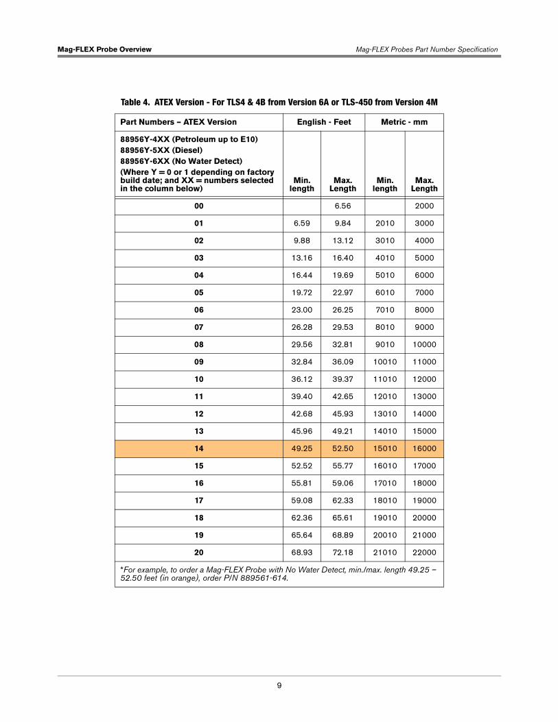
Table 4. ATEX Version - For TLS4 & 4B from Version 6A or TLS-450 from Version 4M
Part Numbers – ATEX Version English - Feet Metric - mm
88956Y-4XX (Petroleum up to E10)88956Y-5XX (Diesel)88956Y-6XX (No Water Detect)(Where Y = 0 or 1 depending on factory build date; and XX = numbers selected in the column below)
Min. length
Max. Length
Min. length
Max. Length
00 6.56 2000
01 6.59 9.84 2010 3000
02 9.88 13.12 3010 4000
03 13.16 16.40 4010 5000
04 16.44 19.69 5010 6000
05 19.72 22.97 6010 7000
06 23.00 26.25 7010 8000
07 26.28 29.53 8010 9000
08 29.56 32.81 9010 10000
09 32.84 36.09 10010 11000
10 36.12 39.37 11010 12000
11 39.40 42.65 12010 13000
12 42.68 45.93 13010 14000
13 45.96 49.21 14010 15000
14 49.25 52.50 15010 16000
15 52.52 55.77 16010 17000
16 55.81 59.06 17010 18000
17 59.08 62.33 18010 19000
18 62.36 65.61 19010 20000
19 65.64 68.89 20010 21000
20 68.93 72.18 21010 22000
*For example, to order a Mag-FLEX Probe with No Water Detect, min./max. length 49.25 – 52.50 feet (in orange), order P/N 889561-614.
Mag-FLEX Probe Overview Fafnir BA-350 Protection Device (Surge Protector)
10
MAG-FLEX SPARE PARTS AND ACCESSORIES
Item Part Number
Single-Channel Surge Protector (Wireless Install) 848100-001
Dual-Channel Surge Protector (Wired Install) 848100-002
Overvoltage Protection Device Type BA 350, 2-wire 903313
Leader Cable with M12 Connector 908704 (Spare part only, supplied with all new probes)
FAFNIR USB Adapter [Mag-Flex] 900180
Water Float for Biodiesel 908546
Connecting cable with M12 connector 908704
Fafnir BA-350 Protection Device (Surge Protector)
This section details safety information that is pertinent to the Fafnir Surge Protector only. The Veeder-Root Surge Protector is certified by UL/DEMKO.
The overvoltage protection device is intended to protect intrinsic safety sensor apparatus from overvoltage eventually caused by atmospheric static electricity and conveyed by the connecting cables.
INFORMATION ON SAFE USE
The equipment is for use of discharge overvoltage and is designed as a simple apparatus according to EN/IEC 60079-11, clause 5.7. Therefore, it can be used without a type examination certificate inside potentially explosive atmospheres (zone 1 and zone 2). The overvoltage protection is for use of all gas groups (IIA, IIB, and IIC) and its temperature class is T6.
The overvoltage protection is enclosed by a metal enclosure. The material composition of the enclosure includes according to EN/IEC 60079-0, clause 8.1.2 for an EPL Gb less than 7,5% magnesium and titan, such as AlSi12.
This instruction manual is valid of types BA 350-X.
INFORMATION ON SAFE MOUNTING RESP. DEMOUNTING
The overvoltage protection is built-on a metal enclosure with a degree of protection IP66. For the installation the housing cover has to be removed (four screws) and it has to be put in place and tight again by the screws after the connection of the wirings. Cable glands have to be tight as appropriate to maintain the IP 66 grade of protection.
INFORMATION ON SAFE INSTALLATION
The wiring may only take place de-energized. Special regulations, among other things, EN/IEC 60079-14 resp. EN/IEC 60079-25 resp. the local installation regulations should be noted. Wall mounting of the overvoltage protection is possible.
General remark (see also EN/IEC 60079-25, clause 12 resp. EN/IEC 60079-14, clause 12.3): The overvoltage protection device must be installed outside zone 0 but as near as technical possible to the boundary of zone 0, preferable in a distance of maximum 1m.
Both terminal blocks can be used either as an input or output. Polarity must be observed.
For the connection to the potential equalisation (PA) a terminal on the outside of the enclosure is provided.

Mag-FLEX Probe Overview Fafnir BA-350 Protection Device (Surge Protector)
11
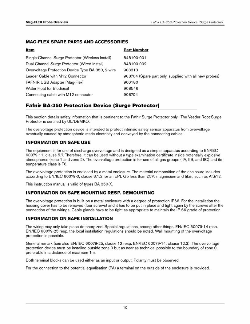
Figure 1. View Into Open Enclosure Of A BA-350-2
INFORMATION ON SAFE ADJUSTMENT
There are no required safety adjustments.
INFORMATION ON SAFE PUTTING INTO SERVICE
Before putting the Mag-FLEX probe into service, double check connections and mounting.
INFORMATION ON SAFE MAINTENANCE AND REPAIRING
In general, the equipment is maintenance free. Defective equipment must be returned to the manufacturer or one it’s representatives. If a test is required, it must be conducted under well-controlled conditions (an explosive atmosphere shall not be present). It is also necessary to disconnect the overvoltage discharge device, according to EN/IEC 60079-25, clause 12, because of a non-conformance with EN/IEC 60079-11, clause 6.3.13.
Surge Arrestors
Outside Terminal Terminal Blocks

Mag-FLEX Probe Overview Mag-FLEX Probe Length Calculation
12
Mag-FLEX Probe Length Calculation
Before ordering the Mag-FLEX Probe, an accurate dimension for “A” must be obtained. Measure internally the Insertion Length ‘A’ from the 1½” entry point to the bottom of the tank (see diagram below). Probe length for ordering purposes = A + 250 mm.
Probe Handling
It is important to handle the Mag-FLEX probe with care at all times during the installation. Avoid excessive bending of the probe especially at the points the ridged sections meet with the flexible shaft. Below you can see examples of mishandling that would cause irreversible damage to the probe and invalidate the terms of warranty.

13
System Safety Layout
Conduit/ducting requirements are dependent on local electrical regulations.
Substitution of components may impair intrinsic safety. Probe, probe wiring and con-sole wiring are intrinsically safe only when connected via this barrier.
Field Cable Ducting / Cable Trays
Explosion could occur if other wires share ducts with intrinsically safe cir-cuits. Ducting from probes or sensors must not contain any other wiring.
FAILURE TO COMPLY WITH THE FOLLOWING WARNINGS AND SAFETY PRECAU-TIONS COULD CAUSE DAMAGE TO PROPERTY, ENVIRONMENT, RESULTING IN SE-RIOUS INJURY OR DEATH.
Minimum diameters for underground probe ducting are:
• Up to 20 cables -100 mm diameter
• Up to 50 cables -150 mm diameter
Run suitable diameter cable ducting and / or cable trays from the TLS Console to each Mag-FLEX probe location. For underground tanks, all cable duct entry points must be sealed to prevent the escape of hydrocarbon vapour and liquid and the ingress of water. Cable duct & cable tray plans must be designed to suit local site requirements and must conform to local/national regulations and industry standards.
For multiple TLS installations, the Mag probe and Mag-FLEX cabling for one TLS system must be contained in separate cable duct or tray to those cables belonging to another TLS system. Combining cables from different TLS systems will be in violation of the intrinsically safe approval for this system and is not permitted. Combining cables from different systems may also result in improper system operation.
Unless specified otherwise, any draw pits should be sited at 10 metre intervals or where acute cable duct angles are unavoidable.
Ensure that all ducting is equipped with cable pull through ropes and that all visible cable ducts are properly fixed and finished off in a neat and tidy manner.
All above ground cable runs should be properly secured and adequately protected from accidental damage.
Cable Specifications For Intrinsically Safe Apparatus Cabling
Cable must be installed to comply with local and national regulations in force at the time of installation. It is the Installer’s responsibility to ensure that the installation complies with all relevant local and national legislation and codes of practice.
Do not run the Mag-FLEX probe cable from the tank to the TLS Console in the same cable duct as non-intrinsically safe wiring.
Gilbarco Veeder-Root requires the use of shielded cable for Mag-FLEX cabling. The cable must have a minimum conductor CSA of 0.75 mm² and must meet with intrinsically safe system installation requirements. The cable capacitance, inductance and L/R ratio must conform to the intrinsically safe output characteristics of the TLS Console and the intrinsically safe input characteristics of the Mag-FLEX probe.
Field Cable, ATG to Probe 2 x 0.75 mm² shielded: i.e. Gilbarco Veeder-Root cable p.n. 222-001-0029.
The TLS Console to Mag-FLEX probe cable length must not exceed 300 meters.
NOTICE
WARNING
WARNING
WARNING
NOTICE

14
Mag-FLEX Installation And Handling Procedure
Probe Installation Requirements
The instructions herein are intended as reference material only, the Gilbarco Veeder-Root training modules contain comprehensive information and must be completed before any installation work is attempted - contact Gilbarco Veeder-Root for details.
Installation requires a minimum of two people to allow correct handling of the probe. Please note that the flexible and therefore fragile nature of the Mag-FLEX probe makes it more prone to mechanical shock. The probe must not be unpacked until it has been brought to its place of installation and where possible unpacked at the Tank top. The probe corrugated shaft is supplied in a 1 meter diameter coil this coil MUST not be reduced in size. The packaged curve is the maximum bend possible to prevent damage.
Miscellaneous Requirements
TANK ENTRY
The tank entry point provided must have an internal thread of 1½” BSP - or 4” BSP when installing a low level water float.
PROBE ASSEMBLY
The process connection, water float, product float, weight and magnet are shipped pre-assembled on the probe.
TOOLS AND MATERIALS
Before starting the installation you should have the following tools & materials:
• Mag-FLEX probe suitable for the tank height. See Mag-FLEX Probe Length Calculation on page 12.
• 2-Core probe cable run from TLS location to tank top. See Cable Specifications For I.S. Apparatus Cabling on page 13.
• Surge protector BA-350 Part number 903313 (wired install only), or V-R P/N 848100-002 for wired install or V-R P/N 848100-001 for wireless install
• Non-sparking 55 mm Spanner for the process connection 55mm WAF (Width across Flat)
• Liquid sealing material for process connection, compatible with the tank material & product to be monitored
• Non-sparking Hexagon key (5mm) for the locking screw
• Non-sparking 30mm Spanner for the gland 30mm WAF (Width across Flat)
• Measuring tape to establish the correct position to lock the probe shaft into place
NOTICE
Mag-FLEX Installation And Handling Procedure Mag-FLEX Probe Installation
15
Mag-FLEX Probe Installation
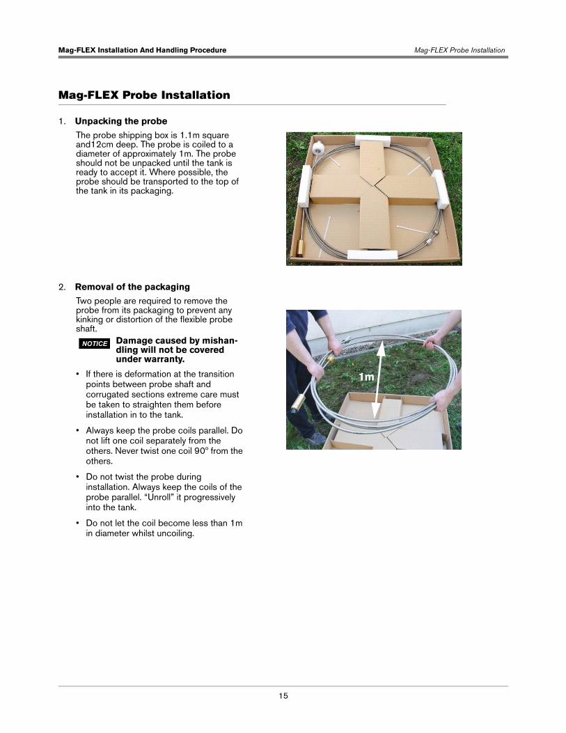
1. Unpacking the probe
2. Removal of the packaging
The probe shipping box is 1.1m square and12cm deep. The probe is coiled to a diameter of approximately 1m. The probe should not be unpacked until the tank is ready to accept it. Where possible, the probe should be transported to the top of the tank in its packaging.
Two people are required to remove the probe from its packaging to prevent any kinking or distortion of the flexible probe shaft.
Damage caused by mishan-dling will not be covered under warranty.
• If there is deformation at the transition points between probe shaft and corrugated sections extreme care must be taken to straighten them before installation in to the tank.
• Always keep the probe coils parallel. Do not lift one coil separately from the others. Never twist one coil 90º from the others.
• Do not twist the probe during installation. Always keep the coils of the probe parallel. “Unroll” it progressively into the tank.
• Do not let the coil become less than 1m in diameter whilst uncoiling.
NOTICE
1m
Mag-FLEX Installation And Handling Procedure Mag-FLEX Probe Installation
16
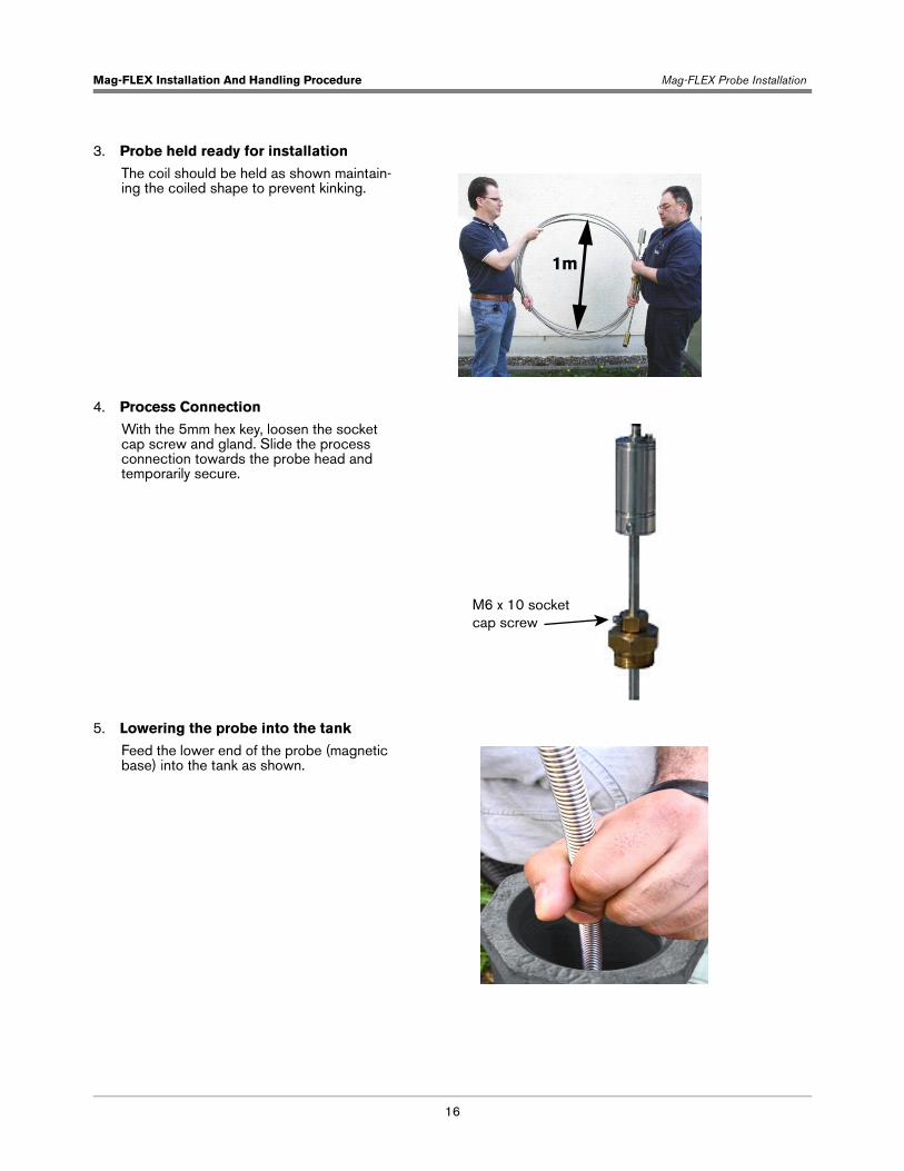
3. Probe held ready for installation
4. Process Connection
5. Lowering the probe into the tank
The coil should be held as shown maintain-ing the coiled shape to prevent kinking.
With the 5mm hex key, loosen the socket cap screw and gland. Slide the process connection towards the probe head and temporarily secure.
Feed the lower end of the probe (magnetic base) into the tank as shown.
1m
M6 x 10 socketcap screw

Mag-FLEX Installation And Handling Procedure Mag-FLEX Probe Installation
17
6. Feeding the probe into the tank
7. Corrugated shaft lowered into tank
8. Installation dimension With the probe in contact with the tank bottom & the probe held taut measure the clearance from the lower edge of the probe canister to the top of the tank entry point (installation dimension) record this measurement.
Unroll the corrugated shaft as the probe is lowered into the tank taking care to avoid chafing on the tank entry.
Steel TanksAt this point lower the probe slowly until you feel the magnetic attraction as it con-tacts the bottom of the tank.
Non Steel tanks Lower the probe until you feel the weight contact the tank bottom.
1m
Record measurement

Mag-FLEX Installation And Handling Procedure Mag-FLEX Probe Installation
18
9. Fitting the process connection
10. Securing the probe
Apply sealant to the thread of the process connection. Carefully lower the process connection into the tank entry fitting. Screw in and tighten using a 55mm WAF spanner..
Raise the probe canister until the exact installation dimension that you measured & recorded in step 8 is achieved.Attention!Do not raise the probe any higher as it will become detached from the bottom of the tank.With the probe in this position tighten the gland nut using a 30mm WAF spanner. Secure the locking screw with the 5mm Hexagon key.
Tighten processconnectionwith 55mmspanner
Then securesocket caplocking screwwith 5mm hexkey
Earthconnector
First tightengland with 30mmspanner

Mag-FLEX Installation And Handling Procedure Mag-FLEX Probe Installation
19
11. Example installations
Figure 2. BA-350 Surge Protector Installation Examples
Figure 3. Veeder-Root Single- And Dual-Channel Surge Protector Installation Examples
Transmitter(attached to side of bracket)
Battery pack (in bracket)
Mag-FLEX probecanister
BA-350 Surge Protector
Riser pipe
4mm2 0 groundwire from SurgeProtector to tankground
4mm2 0 groundwire from Probecanister to tankground Mag-FLEX
probecanister
BA-350Surge Protector
Seal off
Conduit with Probefield wiring to ATG
Conduit
038-1
4mm2 0 ground wire from Surge Protector to tankground
4mm2 0 ground wire from Probecanister to tank ground
Example Wireless Installation Example Hardwired Installation
Transmitter(attached to side of bracket)
Battery pack (in bracket)
Mag-FLEX probecanister
Riser pipe
4mm2 0 groundwire from SurgeProtector to tankground
4mm2 0 groundwire from Probecanister to tankground Mag-FLEX
probecanister
Seal off
Conduit with Probefield wiring to ATG
4mm2 0 ground wire from Surge Protector to tankground
4mm2 0 ground wire from Probecanister to tank ground
Example Wireless Installation Example Hardwired Installation
Single ChannelSurge Protector
(P/N 848100-001)Dual Channel
Surge Protector(P/N 848100-002)
Mag-FLEX Installation And Handling Procedure Mag-FLEX Probe-To-Surge Protector Wiring Connections
20
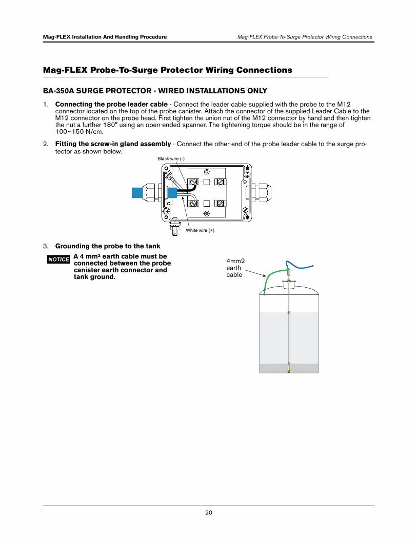
Mag-FLEX Probe-To-Surge Protector Wiring Connections
BA-350A SURGE PROTECTOR - WIRED INSTALLATIONS ONLY
1. Connecting the probe leader cable - Connect the leader cable supplied with the probe to the M12 connector located on the top of the probe canister. Attach the connector of the supplied Leader Cable to the M12 connector on the probe head. First tighten the union nut of the M12 connector by hand and then tighten the nut a further 180° using an open-ended spanner. The tightening torque should be in the range of 100~150 N/cm.
2. Fitting the screw-in gland assembly - Connect the other end of the probe leader cable to the surge pro-tector as shown below.
3. Grounding the probe to the tank
A 4 mm² earth cable must be connected between the probe canister earth connector and tank ground.
Black wire (-)
White wire (+)
NOTICE 4mm2earthcable

Mag-FLEX Installation And Handling Procedure Mag-FLEX Probe-To-Surge Protector Wiring Connections
21
4. Grounding the surge protector to the tank
5. Field cable connection
6. Surge protector cover - Refit the surge protector cover, secure and tidy all wiring to complete the probe in-stallation.
VEEDER-ROOT SURGE PROTECTORS
1. Cut the soft vinyl epoxy enclosure end cap entrance holes of the surge protector to accommodate each cable diameter. Keep the hole sizes to a minimum. Insert about 5 inches (127mm) of each cable through the openings [Figure 4]. Remove 3 inches (76mm) of the outer jacket from each cable. Trim the insulation from the conductors.
Figure 4. Splice Length Dimensions
An 10 gauge (4mm²) eearth cable must be connected between the surge protector and tank ground connection.According to the provision of EN/IEC 60079-14, the minimum size of the earth cable shall be 4 mm². The earth cable should be connected to the external saddle clamp of the surge protector.
Connect the 2 wire field cable from the TLS console probe channel to the surge protector as shown below. Correct polarity MUST be maintained. The field cable length should not exceed 300 metres.
NOTICE
4mm2 minimum earthcable to tank ground
Saddle clamp
Probe leader cable
Field cable toTLS console
Surge protector cap
TLScable
Probecable
Probecable
Shield wire
BlackWhite
WhiteBlack
Surge protector cap
TransmitterCable
Shield wire
BlackWhite
WhiteBlack
2”(51mm)
3”(76mm)
2”(51mm)
3”(76mm)
Dual Channel (Wired Installations) Single Channel (Wireless Installations)

Mag-FLEX Installation And Handling Procedure Mag-FLEX Probe-To-Surge Protector Wiring Connections
22
2. Make the connections to the four black and white wires in the surge protector using wire nuts as shown in Figure 5. Depending on the installation, cut off the TLS console or Transmitter cable’s bare shield wire at the cable jacket.
Figure 5. Splice Connections
3. Center the splices in the clear plastic sleeve. Assemble the surge protector closure, making sure the sleeve is fully inserted into each of the vinyl end caps. Rotate the sleeve cover until both slot openings line up. Arrange the closure so the slot openings are facing up and the surge protector is as level as possible.
4. Remove bag of “Sealing compound” from foil package. Grasp the ends, one in each hand, then pull sharply to remove plastic clip [Figure 6].
WARNING!Sealing compound contains isocyanate. Vapor and liquid may cause sensitization. May be irritating to the eyes.
Avoid skin and eye contact. Avoid repeated and prolonged breathing of vapor. Use only in well ventilated areas. Wear chemically resistant gloves.
Inhalation - provide fresh air. In case of eye contact flush eyes with plenty of water for 10 minutes and get medical attention. If ingested do not induce vomiting. Get medical attention. Wash with soap and water in case of skin contact.
Cable from Transmitter
Connect Probe white to Surge Protector white
Connect Probe black to Surge Protector black
Connect Transmitter blackto Surge Protector blackConnect Transmitter whiteto Surge Protector white
EnclosureBare drain wire (cut back to cable jacket)
Cable from probeCable from TLS
Connect Probe white to Surge Protector white
Connect Probe black to Surge Protector black
Connect TLS white to Surge Protector white
Connect TLS black to Surge Protector black
EnclosureBare drain wire (cut back to cable jacket)
Cable from probe
4mm2 mimumGreen/Yellowground wire
4mm2 mimumGreen/Yellowground wire
Dual Channel - Wired Installations Single Channel - Wireless Installations

Mag-FLEX Installation And Handling Procedure Mag-FLEX Probe-To-Surge Protector Wiring Connections
23
Figure 6. Removing Sealing Compound Clip
5. Thoroughly mix compound together. Invert bag several times while squeezing compound from one end to the other for a minimum of one minute.
6. Once the mixture feels warm, immediately cut one corner and slowly fill the surge protector’s plastic sleeve. Stop just short of filling the entire sleeve. Do not overfill. [Figure 7]
Figure 7. Pouring Sealing Compound Into Sleeve
7. With a twisting motion, rotate the outer clear plastic barrel to close the pouring slot.Wait at least five minutes, then use the large cable tie to mount the surge protector to the riser pipe or probe canister as applicable.
8. An earth cable must be connected between the surge protector and a tank ground connection. According to the provision of EN/IEC 60079-14, the minimum size of the earth cable shall be 4 mm².
Connect the green/yellow ground wire from the surge protector to an appropriate tank ground (see Figure 3 ).
13149-C
NOTICE

Mag-FLEX Installation And Handling Procedure TLS Setup
24
TLS Setup
The TLS console Mag-FLEX setup is similar to that for a standard Mag Plus Probe setup. Listed below are the setup exceptions.
• Float Type - For TLS2, TLS-3XX or TLS-450 consoles, the float type must be set as 3” FLOAT (76.2 mm). Notes: 1. This is the default float type. 2. Water detection starts at 5” (127 mm) therefore water height warnings and alarms should be set above 5”.3. See manual 577014-056 for setup instructions when installing a low level water float.
• Tank Profile - Select ‘Linear’ for TLS2, TLS-3XX or TLS-450 consoles, or ‘Multi-Point’ if an accurate tank chart is available.
• Tank Diameter - For vertical cylindrical tanks, enter the full tank height here (NOT the diameter of the cylinder). Full height is the distance from the bottom of the tank to the top of the cylinder excluding the domed lid at the top of the tank. Set the height in mm.
Exit setup mode and check the inventory report, the water reading should now be “0”. Check all TLS setup parameters are correct. If necessary, secure all console doors.

A-1
Appendix A: Mag-FLEX Safety Information
Equipment Marking
Mag-FLEX probe
1. Manufacturer: Veeder Root Co., Duncansville, PA – USA
2. Type designation: Mag-FLEX
3. Certificate number: TÜV 12 ATEX 105828 – IECEx TUN 12.0027
4. ATEX marking: II 1 G, II 1/2 G, II 2 G
5. EN/IEC marking: Ex ia IIB T4 Ga, Ex ia IIB T4 Ga/Gb, Ex ia IIB T4 Gb
6. CE marking: 1180
Intrinsically Safe TLS Tank Gauge System
1. EC-Type Examination Type Certificate: DEMKO 06 ATEX 137480X
2. IECEx Certficate of Conformity: IECEx ULD 08.0002X
Technical Data
The intrinsically safe input characteristics of the Mag-FLEX probe are listed below. Refer to the site preparation procedures in this manual for general instructions on safe installation, use and replacement.
The above values are to be used when assembling a system in the field when for calculating its maximum cable run (field + sensor cable).
When used in potentially explosive atmospheres, the maximum temperatures depending on the temperature classes and categories can be found in Table A-1.
Parameter
Ui 13 V
Ii 200 mA
Pi 625 mW
Li 410 µHCi 20 nF
Table A-1. Temperature Class Ta Tf
Temperature Class
Ambient Temperature Range
MediumTemperature
Category 1 and EPL Ga (Filling level sensor entirely erected in Zone 0)
T4, T3, T2, T1 -20°C to +60°C -20°C to +60°C
Category 1/2 and EPL Ga/Gb (Sensor pipe erected in Zone 0, Sensor head erected in Zone 1)
T4, T3, T2, T1 -40°C to +75°C -20°C to +60°C

Appendix A: Mag-FLEX Safety Information Specific Conditions of Use
A-2
It must be ensured through appropriate measures that at no point on the sensor head the temperature (Ta) for the respective temperature class is exceeded.
General information (see also EN/IEC 60079 0, clause 1):
Zone 0 is given only under atmospheric conditions:
Temperature range: -20 °C … +60 °C
Pressure range: 0,8 bar … 1,1 bar
Oxidants: Air (oxygen content of about 21%)
Specific Conditions of Use
None.
Category 2 and EPL Gb (Filling level sensor entirely erected in Zone 1)
T4 -40°C to +75°C -40°C to +135°C
T3 -40°C to +75°C -40°C to +200°C
T1 -40°C to +75°C -40°C to +300°C
T1 -40°C to +75°C -40°C to +450°C
Table A-1. Temperature Class Ta Tf
Temperature Class
Ambient Temperature Range
MediumTemperature
