magelis xbt n/r/rt compact display units user manual xbt n&r manual.pdf · magelis xbt n/r/rt...
TRANSCRIPT
3300
3962
.01
Magelis XBT N/R/RTCompact Display UnitsUser Manual33003962 06/2008

2 33003962 06/2008
Table of Contents
Safety Information . . . . . . . . . . . . . . . . . . . . . . . . . . . . . . . . . . . .7
About the Book . . . . . . . . . . . . . . . . . . . . . . . . . . . . . . . . . . . . . . .9
Chapter 1 Document Conventions . . . . . . . . . . . . . . . . . . . . . . . . . . . . . . .11
Chapter 2 Overview . . . . . . . . . . . . . . . . . . . . . . . . . . . . . . . . . . . . . . . . . . .13Standards and General Safety Precautions . . . . . . . . . . . . . . . . . . . . . . . . . . . . 13
Chapter 3 Characteristics of the XBT Terminal Range. . . . . . . . . . . . . . .173.1 Characteristics of the XBT Terminal Range . . . . . . . . . . . . . . . . . . . . . . . . . . . . 19
Characteristics Applying to All XBT Terminals . . . . . . . . . . . . . . . . . . . . . . . . . . 20Characteristics of the Individual XBT Terminals . . . . . . . . . . . . . . . . . . . . . . . . . 21Polling Times. . . . . . . . . . . . . . . . . . . . . . . . . . . . . . . . . . . . . . . . . . . . . . . . . . . . 28
Chapter 4 Operating Elements, LEDs and Connectors . . . . . . . . . . . . . .314.1 Operating Elements, LEDs and Connectors . . . . . . . . . . . . . . . . . . . . . . . . . . . . 33
Front Panels . . . . . . . . . . . . . . . . . . . . . . . . . . . . . . . . . . . . . . . . . . . . . . . . . . . . 34Rear Panels. . . . . . . . . . . . . . . . . . . . . . . . . . . . . . . . . . . . . . . . . . . . . . . . . . . . . 38Overview of Keys on the Individual XBT Terminals . . . . . . . . . . . . . . . . . . . . . . 39
Chapter 5 Insert Labels . . . . . . . . . . . . . . . . . . . . . . . . . . . . . . . . . . . . . . . .455.1 Insert Labels . . . . . . . . . . . . . . . . . . . . . . . . . . . . . . . . . . . . . . . . . . . . . . . . . . . . 47
Insert Labels XBT N . . . . . . . . . . . . . . . . . . . . . . . . . . . . . . . . . . . . . . . . . . . . . . 48Insert Labels XBT R . . . . . . . . . . . . . . . . . . . . . . . . . . . . . . . . . . . . . . . . . . . . . . 50Insert Labels XBT RT . . . . . . . . . . . . . . . . . . . . . . . . . . . . . . . . . . . . . . . . . . . . . 52
Chapter 6 Inserting Labels . . . . . . . . . . . . . . . . . . . . . . . . . . . . . . . . . . . . .55
Chapter 7 Creating Individual Labels . . . . . . . . . . . . . . . . . . . . . . . . . . . . .61
Chapter 8 Connecting XBT Terminals . . . . . . . . . . . . . . . . . . . . . . . . . . . .658.1 Grounding and Safety . . . . . . . . . . . . . . . . . . . . . . . . . . . . . . . . . . . . . . . . . . . . . 67
Safety Information Concerning the Grounding of Terminals . . . . . . . . . . . . . . . . 678.2 Connecting XBT Terminals to a PC . . . . . . . . . . . . . . . . . . . . . . . . . . . . . . . . . . 69
Distinguishing XBT Terminals by Power Supply . . . . . . . . . . . . . . . . . . . . . . . . 70Connecting XBT Terminals Powered by the PLC to a PC . . . . . . . . . . . . . . . . . 71
33003962 06/2008 3
Connecting XBT Terminals Powered by an External Power Supply to a PC. . . . 748.3 Connecting XBT Terminals to a PLC. . . . . . . . . . . . . . . . . . . . . . . . . . . . . . . . . . 77
Distinguishing XBT Terminals by Power Supply . . . . . . . . . . . . . . . . . . . . . . . . . 78Connecting XBT Terminals Powered by the PLC to a PLC. . . . . . . . . . . . . . . . . 80Connecting XBT Terminals Powered by an External Power Supply to a PLC. . . 84
8.4 Connecting XBT N401 / R411 / RT511 Terminals to a Printer . . . . . . . . . . . . . . 89Printer Connections . . . . . . . . . . . . . . . . . . . . . . . . . . . . . . . . . . . . . . . . . . . . . . . 89
Chapter 9 Overview of Applications and Functions . . . . . . . . . . . . . . . . 919.1 Overview of Functions . . . . . . . . . . . . . . . . . . . . . . . . . . . . . . . . . . . . . . . . . . . . . 93
Overview of XBT Terminal Functions . . . . . . . . . . . . . . . . . . . . . . . . . . . . . . . . . 939.2 XBT Terminals in HMI Applications . . . . . . . . . . . . . . . . . . . . . . . . . . . . . . . . . . . 94
HMI Applications . . . . . . . . . . . . . . . . . . . . . . . . . . . . . . . . . . . . . . . . . . . . . . . . . 949.3 Functions of Keys, Touchscreen, LEDs. . . . . . . . . . . . . . . . . . . . . . . . . . . . . . . . 97
Functions of Keys and Touchscreen . . . . . . . . . . . . . . . . . . . . . . . . . . . . . . . . . . 98Functions of LEDs on XBT N401 / XBT R411 / XBT RT511 Terminals. . . . . . . 101
Chapter 10 Operating Principles of XBT Terminals . . . . . . . . . . . . . . . . . 10310.1 Modes of Operation . . . . . . . . . . . . . . . . . . . . . . . . . . . . . . . . . . . . . . . . . . . . . . 105
Introduction . . . . . . . . . . . . . . . . . . . . . . . . . . . . . . . . . . . . . . . . . . . . . . . . . . . . 106Automatic Selection of the Mode of Operation . . . . . . . . . . . . . . . . . . . . . . . . . 107Transfer Mode . . . . . . . . . . . . . . . . . . . . . . . . . . . . . . . . . . . . . . . . . . . . . . . . . . 108Operating Mode . . . . . . . . . . . . . . . . . . . . . . . . . . . . . . . . . . . . . . . . . . . . . . . . . 110
10.2 Panel Structure of XBT Terminals . . . . . . . . . . . . . . . . . . . . . . . . . . . . . . . . . . . 112Principle of Application Panels. . . . . . . . . . . . . . . . . . . . . . . . . . . . . . . . . . . . . . 113Displaying Application Panels . . . . . . . . . . . . . . . . . . . . . . . . . . . . . . . . . . . . . . 114Principle of Alarm Panels. . . . . . . . . . . . . . . . . . . . . . . . . . . . . . . . . . . . . . . . . . 118Alarm Management . . . . . . . . . . . . . . . . . . . . . . . . . . . . . . . . . . . . . . . . . . . . . . 119Principle of System Panels . . . . . . . . . . . . . . . . . . . . . . . . . . . . . . . . . . . . . . . . 122Displaying System Panels . . . . . . . . . . . . . . . . . . . . . . . . . . . . . . . . . . . . . . . . . 123Scrolling within Panels . . . . . . . . . . . . . . . . . . . . . . . . . . . . . . . . . . . . . . . . . . . . 124
10.3 General Configuration Settings . . . . . . . . . . . . . . . . . . . . . . . . . . . . . . . . . . . . . 125Accessing Configuration Parameters via the System Panel SYSTEM . . . . . . . 126Selecting the HMI Language . . . . . . . . . . . . . . . . . . . . . . . . . . . . . . . . . . . . . . . 127Selecting the Date and Time Format . . . . . . . . . . . . . . . . . . . . . . . . . . . . . . . . . 128Accessing the Product Reference . . . . . . . . . . . . . . . . . . . . . . . . . . . . . . . . . . . 129Accessing the Line Parameters . . . . . . . . . . . . . . . . . . . . . . . . . . . . . . . . . . . . . 130
10.4 Password-Protection . . . . . . . . . . . . . . . . . . . . . . . . . . . . . . . . . . . . . . . . . . . . . 131Accessing Password-Protected Panels, Fields, Functional Links . . . . . . . . . . . 131
Chapter 11 Communication Between XBT Terminals and the Automation System . . . . . . . . . . . . . . . . . . . . . . . . . . . . . . . . . . . . . . . . . . . 133
11.1 Types of Commands . . . . . . . . . . . . . . . . . . . . . . . . . . . . . . . . . . . . . . . . . . . . . 135Impulse Commands. . . . . . . . . . . . . . . . . . . . . . . . . . . . . . . . . . . . . . . . . . . . . . 136Toggle Commands. . . . . . . . . . . . . . . . . . . . . . . . . . . . . . . . . . . . . . . . . . . . . . . 137
11.2 Activating Commands . . . . . . . . . . . . . . . . . . . . . . . . . . . . . . . . . . . . . . . . . . . . 138
4 33003962 06/2008
Activating Commands via Functional Links, Button Objects or Dynamic Function Keys on the Display Unit . . . . . . . . . . . . . . . . . . . . . . . . . . . . . . . . . . . . . . . . . . 139Activating Commands via Function Keys on the Display Unit. . . . . . . . . . . . . . 144
11.3 Entering / Modifying Values Alphanumeric Fields in Edition Mode . . . . . . . . . . 145Accessing an Alphanumeric Edition Field . . . . . . . . . . . . . . . . . . . . . . . . . . . . . 146Entering a Value in an Edition Field . . . . . . . . . . . . . . . . . . . . . . . . . . . . . . . . . 148Confirming / Cancelling an Edition . . . . . . . . . . . . . . . . . . . . . . . . . . . . . . . . . . 150Exit Edition on Time Out . . . . . . . . . . . . . . . . . . . . . . . . . . . . . . . . . . . . . . . . . . 151Edition Report . . . . . . . . . . . . . . . . . . . . . . . . . . . . . . . . . . . . . . . . . . . . . . . . . . 152
11.4 Handling Alarms . . . . . . . . . . . . . . . . . . . . . . . . . . . . . . . . . . . . . . . . . . . . . . . . 153Viewing or Ignoring Alarms . . . . . . . . . . . . . . . . . . . . . . . . . . . . . . . . . . . . . . . . 154Alarm Log . . . . . . . . . . . . . . . . . . . . . . . . . . . . . . . . . . . . . . . . . . . . . . . . . . . . . 156
11.5 Printing Alarms . . . . . . . . . . . . . . . . . . . . . . . . . . . . . . . . . . . . . . . . . . . . . . . . . 157Principles of Printing Alarms . . . . . . . . . . . . . . . . . . . . . . . . . . . . . . . . . . . . . . . 158Printing Alarms as a Data Stream. . . . . . . . . . . . . . . . . . . . . . . . . . . . . . . . . . . 159Printing the Alarm Log. . . . . . . . . . . . . . . . . . . . . . . . . . . . . . . . . . . . . . . . . . . . 160
Chapter 12 Vijeo-Designer Lite Configuration Software . . . . . . . . . . . . .161Creating XBT Terminal Applications . . . . . . . . . . . . . . . . . . . . . . . . . . . . . . . . . 162Exchanging Data with the Automation System via the Dialog Table. . . . . . . . . 163
Appendices . . . . . . . . . . . . . . . . . . . . . . . . . . . . . . . . . . . . . . . . . . . . . 165
Appendix A Troubleshooting and Further Information . . . . . . . . . . . . . . .167Troubleshooting. . . . . . . . . . . . . . . . . . . . . . . . . . . . . . . . . . . . . . . . . . . . . . . . . 168System Messages. . . . . . . . . . . . . . . . . . . . . . . . . . . . . . . . . . . . . . . . . . . . . . . 170Internal Variables . . . . . . . . . . . . . . . . . . . . . . . . . . . . . . . . . . . . . . . . . . . . . . . 172Terminal Self-Tests . . . . . . . . . . . . . . . . . . . . . . . . . . . . . . . . . . . . . . . . . . . . . . 174
Appendix B Architectures of Automation Systems . . . . . . . . . . . . . . . . . .175
Glossary . . . . . . . . . . . . . . . . . . . . . . . . . . . . . . . . . . . . . . . . . . . . . 179
Index . . . . . . . . . . . . . . . . . . . . . . . . . . . . . . . . . . . . . . . . . . . . . 189
33003962 06/2008 5

6 33003962 06/2008
§
Safety InformationImportant Information
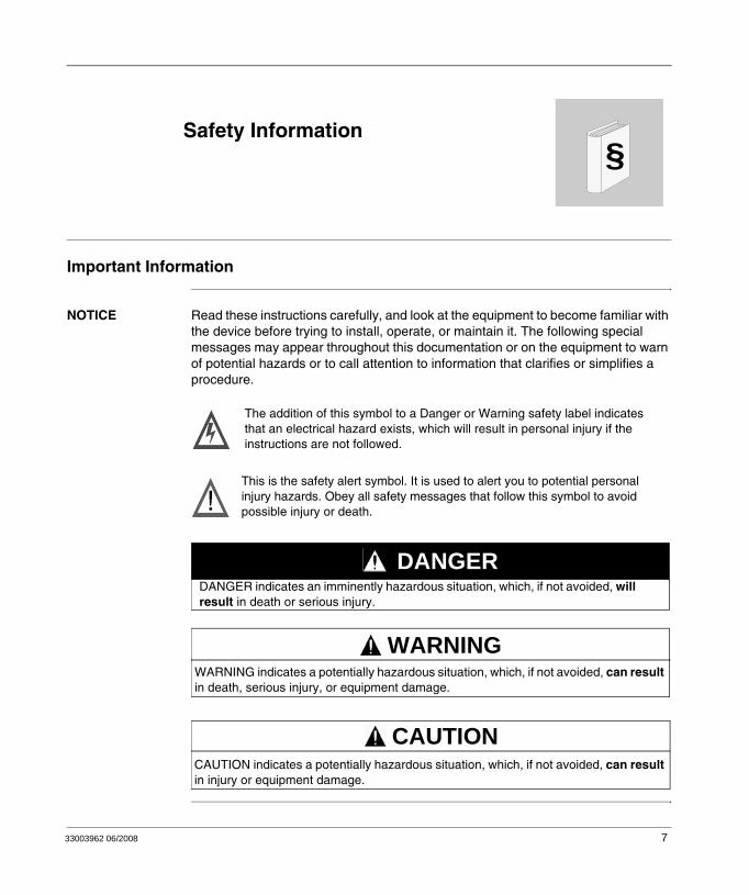
NOTICE Read these instructions carefully, and look at the equipment to become familiar with the device before trying to install, operate, or maintain it. The following special messages may appear throughout this documentation or on the equipment to warn of potential hazards or to call attention to information that clarifies or simplifies a procedure.
The addition of this symbol to a Danger or Warning safety label indicatesthat an electrical hazard exists, which will result in personal injury if theinstructions are not followed.
This is the safety alert symbol. It is used to alert you to potential personalinjury hazards. Obey all safety messages that follow this symbol to avoidpossible injury or death.
DANGER indicates an imminently hazardous situation, which, if not avoided, will result in death or serious injury.
DANGER
WARNING indicates a potentially hazardous situation, which, if not avoided, can result in death, serious injury, or equipment damage.
WARNING
CAUTION indicates a potentially hazardous situation, which, if not avoided, can result in injury or equipment damage.
CAUTION
33003962 06/2008 7
Safety Information
PLEASE NOTE Electrical equipment should be installed, operated, serviced, and maintained only by qualified personnel. No responsibility is assumed by Schneider Electric for any consequences arising out of the use of this material.
© 2008 Schneider Electric. All Rights Reserved.
8 33003962 06/2008
About the Book
At a Glance
Document Scope This manual describes how to use the Magelis XBT N/R/RT device.
Validity Note Schneider Electric assumes no responsibility for any errors that may appear in this document. If you have suggestions for improvements or amendments or have found errors in this publication, please notify us.
No part of this document may be reproduced in any form or by any means, electronic or mechanical, including photocopying, without express written permission of Schneider Electric.
The data and illustrations found in this documentation are not binding. We reserve the right to modify our products in line with our policy of continuous product development. The information in this document is subject to change without notice and should not be construed as a commitment by Schneider Electric.
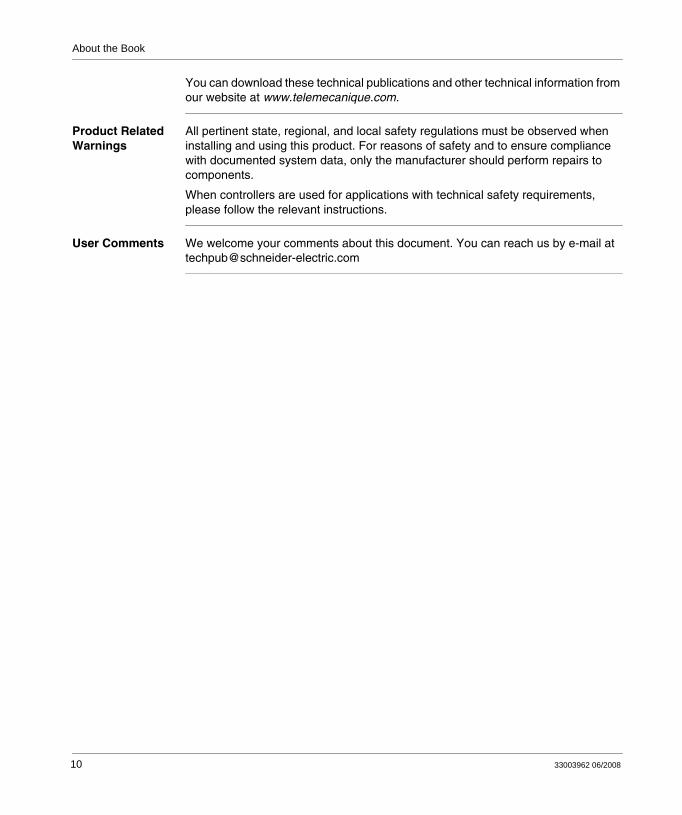
Related Documents
Title of Documentation Reference Number
Vijeo-Designer Lite Online help
Modbus Master Protocol XBT N/R/RT 33003986
Modbus SlaveProtocol XBT N/R/RT 33003980
Uni-Telway Protocol XBT N/R/RT 33003974
Siemens PPI Protocol XBT N/R/RT 33003992
AB DF1 Protocol XBT N/R/RT 33003998
AB DH485 Protocol XBT N/R/RT 33004016
Mitsubishi FX Protocol XBT N/R/RT 33004004
SYSMAC-WAY Protocol XBT N/R/RT 33004010
33003962 06/2008 9
About the Book
You can download these technical publications and other technical information from our website at www.telemecanique.com.
Product Related Warnings
All pertinent state, regional, and local safety regulations must be observed when installing and using this product. For reasons of safety and to ensure compliance with documented system data, only the manufacturer should perform repairs to components.
When controllers are used for applications with technical safety requirements, please follow the relevant instructions.
User Comments We welcome your comments about this document. You can reach us by e-mail at [email protected]
10 33003962 06/2008
33003962 06/2008
1
Document ConventionsGeneral information
Pictograms The meaning of the pictograms used in this document is explained below.
Pictogram Description
Indicates information concerning the communication LED.
Indicates information concerning LEDs in general.
Represents a button on the Vijeo-Designer Lite program toolbar.
Represents a button on the XBT terminal.
11

Document Conventions
12 33003962 06/2008
33003962 06/2008
2
OverviewStandards and General Safety Precautions
List of Standards XBT terminals have been developed to conform to the following standards:
UL 508 for Industrial Control EquipmentUL 1604 Electrical Equipment for Use in Class I and Class II Division 2 and Class III Hazardous LocationsCAN/CSA-C22.2, No. 14, No. 213, and No. 60950 Industrial Control Equipment Miscellaneous Apparatus - For Hazardous Locations.
13
Overview
General Safety Precautions
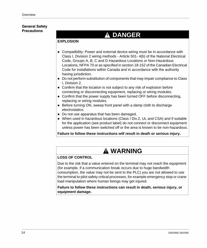
EXPLOSION
Compatibility: Power and external device wiring must be in accordance with Class I, Division 2 wiring methods - Article 501- 4(b) of the National Electrical Code, Groups A, B, C and D Hazardous Locations or Non-Hazardous Locations, NFPA 70 or as specified in section 18-152 of the Canadian Electrical Code for installations within Canada and in accordance with the authority having jurisdiction.Do not perform substitution of components that may impair compliance to Class I, Division 2.Confirm that the location is not subject to any risk of explosion before connecting or disconnecting equipment, replacing or wiring modules.Confirm that the power supply has been turned OFF before disconnecting, replacing or wiring modules.Before turning ON, sweep front panel with a damp cloth to discharge electrostatics.Do not use apparatus that has been damaged.When used in hazardous locations (Class I Div.2, UL and CSA) and if suitable for the application (see product label) do not connect or disconnect equipment unless power has been switched off or the area is known to be non-hazardous.
Failure to follow these instructions will result in death or serious injury.
LOSS OF CONTROLDue to the risk that a value entered on the terminal may not reach the equipment (for example, if a communication break occurs due to huge bandwidth consumption, the value may not be sent to the PLC) you are not allowed to use the terminal to pilot safety critical processes, for example emergency stop or crane load manipulation where human beings may get injured.
Failure to follow these instructions can result in death, serious injury, or equipment damage.
DANGER
WARNING
14 33003962 06/2008
Overview
UNINTENDED EQUIPMENT OPERATION
Read and follow all user instructions and documentation.Follow all local and national product safety codes and standards.
Failure to follow these instructions can result in death, serious injury, or equipment damage.
WARNING
33003962 06/2008 15

Overview
16 33003962 06/2008
33003962 06/2008
3
Characteristics of the XBT Terminal RangeAt a Glance
Overview This chapter presents the different types of XBT terminals with their individual characteristics.
What's in this Chapter?
This chapter contains the following sections:
Section Topic Page
3.1 Characteristics of the XBT Terminal Range 19
17

Characteristics of the XBT Terminal Range
18 33003962 06/2008
Characteristics of the XBT Terminal Range
3.1 Characteristics of the XBT Terminal Range
At a Glance
Overview This section lists the characteristics of the individual versions of the XBT terminal range.
What's in this Section?
This section contains the following topics:
Topic Page
Characteristics Applying to All XBT Terminals 20
Characteristics of the Individual XBT Terminals 21
Polling Times 28
33003962 06/2008 19
Characteristics of the XBT Terminal Range
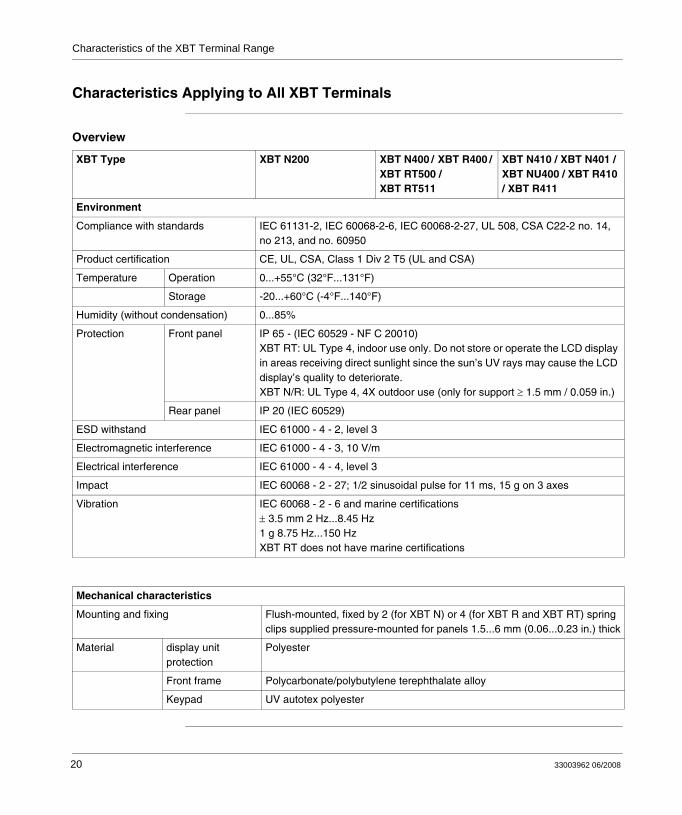
Characteristics Applying to All XBT Terminals
Overview
XBT Type XBT N200 XBT N400 / XBT R400 / XBT RT500 / XBT RT511
XBT N410 / XBT N401 / XBT NU400 / XBT R410 / XBT R411
Environment
Compliance with standards IEC 61131-2, IEC 60068-2-6, IEC 60068-2-27, UL 508, CSA C22-2 no. 14, no 213, and no. 60950
Product certification CE, UL, CSA, Class 1 Div 2 T5 (UL and CSA)
Temperature Operation 0...+55°C (32°F...131°F)
Storage -20...+60°C (-4°F...140°F)
Humidity (without condensation) 0...85%
Protection Front panel IP 65 - (IEC 60529 - NF C 20010)XBT RT: UL Type 4, indoor use only. Do not store or operate the LCD display in areas receiving direct sunlight since the sun’s UV rays may cause the LCD display’s quality to deteriorate.XBT N/R: UL Type 4, 4X outdoor use (only for support ≥ 1.5 mm / 0.059 in.)
Rear panel IP 20 (IEC 60529)
ESD withstand IEC 61000 - 4 - 2, level 3
Electromagnetic interference IEC 61000 - 4 - 3, 10 V/m
Electrical interference IEC 61000 - 4 - 4, level 3
Impact IEC 60068 - 2 - 27; 1/2 sinusoidal pulse for 11 ms, 15 g on 3 axes
Vibration IEC 60068 - 2 - 6 and marine certifications ± 3.5 mm 2 Hz...8.45 Hz1 g 8.75 Hz...150 HzXBT RT does not have marine certifications
Mechanical characteristics
Mounting and fixing Flush-mounted, fixed by 2 (for XBT N) or 4 (for XBT R and XBT RT) spring clips supplied pressure-mounted for panels 1.5...6 mm (0.06...0.23 in.) thick
Material display unit protection
Polyester
Front frame Polycarbonate/polybutylene terephthalate alloy
Keypad UV autotex polyester
20 33003962 06/2008
Characteristics of the XBT Terminal Range
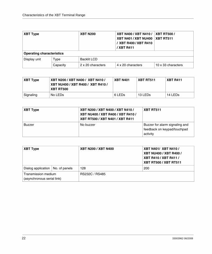
Characteristics of the Individual XBT Terminals
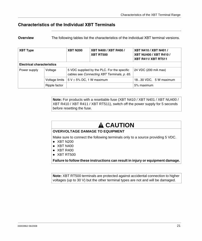
Overview The following tables list the characteristics of the individual XBT terminal versions.
XBT Type XBT N200 XBT N400 / XBT R400 / XBT RT500
XBT N410 / XBT N401 / XBT NU400 / XBT R410 / XBT R411/ XBT RT511
Electrical characteristics
Power supply Voltage 5 VDC supplied by the PLC. For the specific cables see Connecting XBT Terminals, p. 65.
24 VDC (200 mA max)
Voltage limits 5 V ± 5% DC, 1 W maximum 18...30 VDC, 5 W maximum
Ripple factor 5% maximum
Note: For products with a resettable fuse (XBT N410 / XBT N401 / XBT NU400 / XBT R410 / XBT R411 / XBT RT511), switch off the power supply for 5 seconds before resetting the fuse.
OVERVOLTAGE DAMAGE TO EQUIPMENTMake sure to connect the following terminals only to a source providing 5 VDC.
XBT N200XBT N400XBT R400XBT RT500
Failure to follow these instructions can result in injury or equipment damage.
Note: XBT RT500 terminals are protected against accidental connection to higher voltages (up to 30 V) but the other terminal types are not and will be damaged.
CAUTION
33003962 06/2008 21
Characteristics of the XBT Terminal Range
XBT Type XBT N200 XBT N400 / XBT N410 / XBT N401 / XBT NU400 / XBT R400 / XBT R410 / XBT R411
XBT RT500 / XBT RT511
Operating characteristics
Display unit Type Backlit LCD
Capacity 2 x 20 characters 4 x 20 characters 10 x 33 characters
XBT Type XBT N200 / XBT N400 / XBT N410 / XBT NU400 / XBT R400 / XBT R410 / XBT RT500
XBT N401 XBT RT511 XBT R411
Signaling No LEDs 6 LEDs 13 LEDs 14 LEDs
XBT Type XBT N200 / XBT N400 / XBT N410 / XBT NU400 / XBT R400 / XBT R410 / XBT RT500 / XBT N401 / XBT R411
XBT RT511
Buzzer No buzzer Buzzer for alarm signaling and feedback on keypad/touchpad activity
XBT Type XBT N200 / XBT N400 XBT N401/ XBT N410 / XBT NU400 / XBT R400 / XBT R410 / XBT R411 / XBT RT500 / XBT RT511
Dialog application No. of panels 128 200
Transmission medium (asynchronous serial link)
RS232C / RS485
22 33003962 06/2008
Characteristics of the XBT Terminal Range
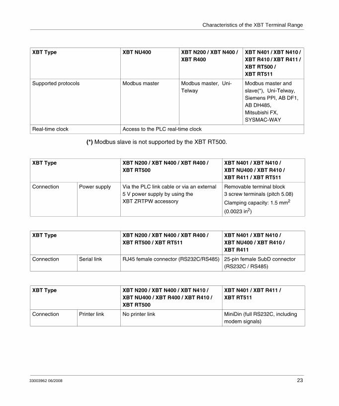
(*) Modbus slave is not supported by the XBT RT500.
XBT Type XBT NU400 XBT N200 / XBT N400 / XBT R400
XBT N401 / XBT N410 / XBT R410 / XBT R411 / XBT RT500 / XBT RT511
Supported protocols Modbus master Modbus master, Uni-Telway
Modbus master and slave(*), Uni-Telway, Siemens PPI, AB DF1, AB DH485, Mitsubishi FX, SYSMAC-WAY
Real-time clock Access to the PLC real-time clock
XBT Type XBT N200 / XBT N400 / XBT R400 / XBT RT500
XBT N401 / XBT N410 / XBT NU400 / XBT R410 / XBT R411 / XBT RT511
Connection Power supply Via the PLC link cable or via an external 5 V power supply by using the XBT ZRTPW accessory
Removable terminal block3 screw terminals (pitch 5.08)
Clamping capacity: 1.5 mm2
(0.0023 in2)
XBT Type XBT N200 / XBT N400 / XBT R400 / XBT RT500 / XBT RT511
XBT N401 / XBT N410 / XBT NU400 / XBT R410 / XBT R411
Connection Serial link RJ45 female connector (RS232C/RS485) 25-pin female SubD connector (RS232C / RS485)
XBT Type XBT N200 / XBT N400 / XBT N410 / XBT NU400 / XBT R400 / XBT R410 / XBT RT500
XBT N401 / XBT R411 / XBT RT511
Connection Printer link No printer link MiniDin (full RS232C, including modem signals)
33003962 06/2008 23
Characteristics of the XBT Terminal Range
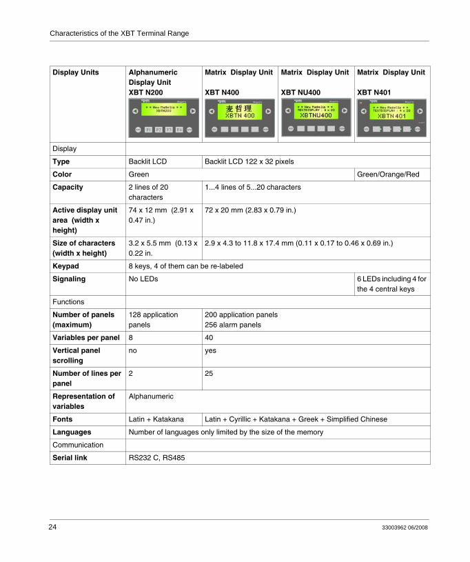
Display Units AlphanumericDisplay UnitXBT N200
Matrix Display Unit XBT N400
Matrix Display Unit XBT NU400
Matrix Display Unit
XBT N401
Display
Type Backlit LCD Backlit LCD 122 x 32 pixels
Color Green Green/Orange/Red
Capacity 2 lines of 20 characters
1...4 lines of 5...20 characters
Active display unit area (width x height)
74 x 12 mm (2.91 x 0.47 in.)
72 x 20 mm (2.83 x 0.79 in.)
Size of characters (width x height)
3.2 x 5.5 mm (0.13 x 0.22 in.
2.9 x 4.3 to 11.8 x 17.4 mm (0.11 x 0.17 to 0.46 x 0.69 in.)
Keypad 8 keys, 4 of them can be re-labeled
Signaling No LEDs 6 LEDs including 4 for the 4 central keys
Functions
Number of panels (maximum)
128 application panels
200 application panels256 alarm panels
Variables per panel 8 40
Vertical panel scrolling
no yes
Number of lines per panel
2 25
Representation of variables
Alphanumeric
Fonts Latin + Katakana Latin + Cyrillic + Katakana + Greek + Simplified Chinese
Languages Number of languages only limited by the size of the memory
Communication
Serial link RS232 C, RS485
24 33003962 06/2008
Characteristics of the XBT Terminal Range
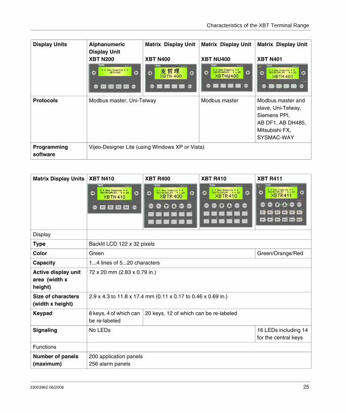
Protocols Modbus master, Uni-Telway Modbus master Modbus master and slave, Uni-Telway, Siemens PPI, AB DF1, AB DH485, Mitsubishi FX, SYSMAC-WAY
Programming software
Vijeo-Designer Lite (using Windows XP or Vista)
Display Units AlphanumericDisplay UnitXBT N200
Matrix Display Unit XBT N400
Matrix Display Unit XBT NU400
Matrix Display Unit
XBT N401
Matrix Display Units XBT N410 XBT R400 XBT R410 XBT R411
Display
Type Backlit LCD 122 x 32 pixels
Color Green Green/Orange/Red
Capacity 1...4 lines of 5...20 characters
Active display unit area (width x height)
72 x 20 mm (2.83 x 0.79 in.)
Size of characters (width x height)
2.9 x 4.3 to 11.8 x 17.4 mm (0.11 x 0.17 to 0.46 x 0.69 in.)
Keypad 8 keys, 4 of which can be re-labeled
20 keys, 12 of which can be re-labeled
Signaling No LEDs 16 LEDs including 14 for the central keys
Functions
Number of panels (maximum)
200 application panels256 alarm panels
33003962 06/2008 25
Characteristics of the XBT Terminal Range
Variables per panel 40
Vertical panel scrolling
yes
Number of lines per panel
25
Representation of variables
Alphanumeric
Fonts Latin + Cyrillic + Katakana + Greek + Simplified Chinese
Languages Number of languages only limited by the size of the memory
Communication
Serial link RS232 C, RS485
Protocols Modbus master and slave, Uni-Telway, Siemens PPI, AB DF1, AB DH485, Mitsubishi FX, SYSMAC-WAY
Modbus master, Uni-Telway
Modbus master and slave, Uni-Telway, Siemens PPI, AB DF1, AB DH485, Mitsubishi FX, SYSMAC-WAY
Programming software
Vijeo-Designer Lite (using Windows XP or Vista)
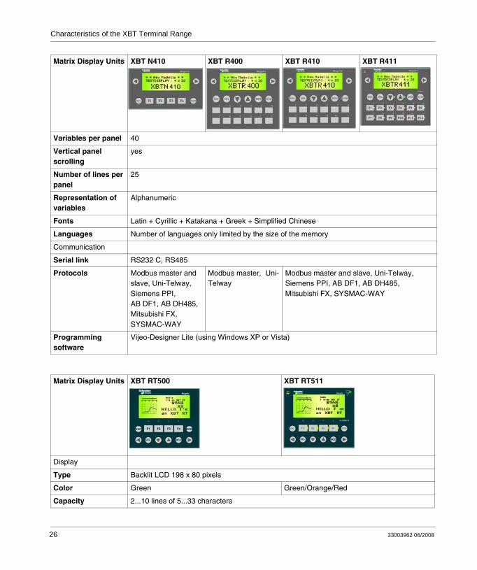
Matrix Display Units XBT N410 XBT R400 XBT R410 XBT R411
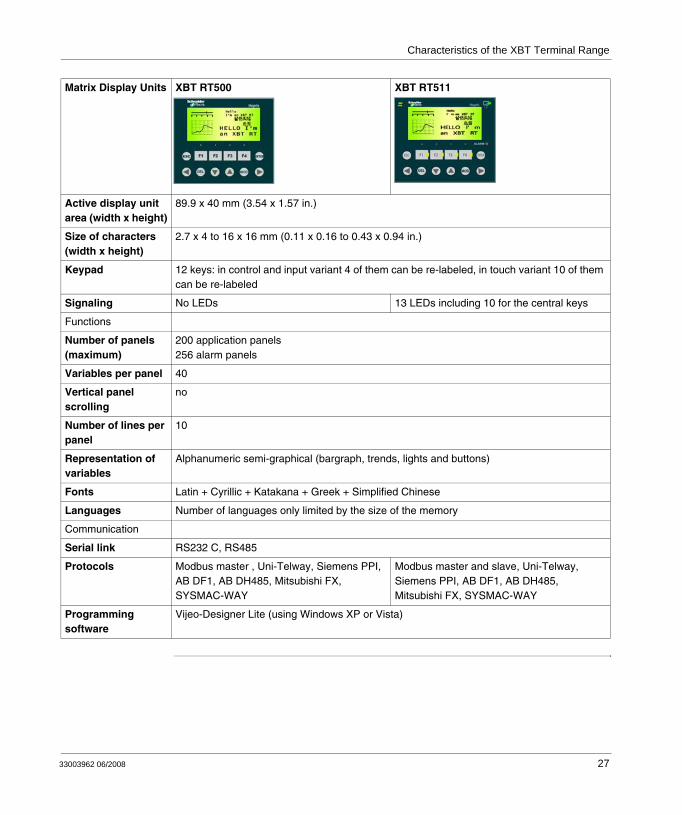
Matrix Display Units XBT RT500 XBT RT511
Display
Type Backlit LCD 198 x 80 pixels
Color Green Green/Orange/Red
Capacity 2...10 lines of 5...33 characters
26 33003962 06/2008
Characteristics of the XBT Terminal Range
Active display unit area (width x height)
89.9 x 40 mm (3.54 x 1.57 in.)
Size of characters (width x height)
2.7 x 4 to 16 x 16 mm (0.11 x 0.16 to 0.43 x 0.94 in.)
Keypad 12 keys: in control and input variant 4 of them can be re-labeled, in touch variant 10 of them can be re-labeled
Signaling No LEDs 13 LEDs including 10 for the central keys
Functions
Number of panels (maximum)
200 application panels256 alarm panels
Variables per panel 40
Vertical panel scrolling
no
Number of lines per panel
10
Representation of variables
Alphanumeric semi-graphical (bargraph, trends, lights and buttons)
Fonts Latin + Cyrillic + Katakana + Greek + Simplified Chinese
Languages Number of languages only limited by the size of the memory
Communication
Serial link RS232 C, RS485
Protocols Modbus master , Uni-Telway, Siemens PPI, AB DF1, AB DH485, Mitsubishi FX, SYSMAC-WAY
Modbus master and slave, Uni-Telway, Siemens PPI, AB DF1, AB DH485, Mitsubishi FX, SYSMAC-WAY
Programming software
Vijeo-Designer Lite (using Windows XP or Vista)
Matrix Display Units XBT RT500 XBT RT511
33003962 06/2008 27
Characteristics of the XBT Terminal Range
Polling Times
Overview The polling times for non-connected equipment differ between XBT N/R/RT terminals and XBT NU400 terminals. The following sections describe general polling times of XBT N/R/RT terminals and specific polling times of XBT NU400 terminals.
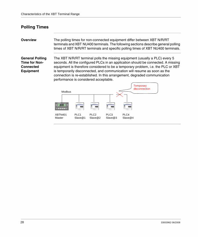
General Polling Time for Non-Connected Equipment
The XBT N/R/RT terminal polls the missing equipment (usually a PLC) every 5 seconds. All the configured PLCs in an application should be connected. A missing equipment is therefore considered to be a temporary problem, i.e. the PLC or XBT is temporarily disconnected, and communication will resume as soon as the connection is re-established. In this arrangement, degraded communication performance is considered acceptable.
Modbus
XBTN401Master
PLC1Slave@1
PLC2Slave@2
PLC3Slave@3
PLC4Slave@4
Temporarydisconnection
28 33003962 06/2008
Characteristics of the XBT Terminal Range
Polling Time of XBT NU400 Terminals
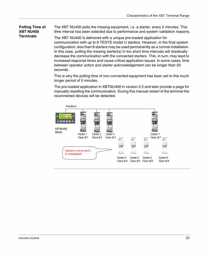
The XBT NU400 polls the missing equipment, i.e. a starter, every 5 minutes. This time interval has been selected due to performance and system validation reasons.
The XBT NU400 is delivered with a unique pre-loaded application for communication with up to 8 TESYS model U starters. However, in the final system configuration, less than 8 starters may be used permanently as a normal installation. In this case, polling the missing starter(s) in too short time intervals will drastically decrease the communication with the connected starters. This, in turn, may lead to increased response times and cause critical application issues. In some cases, time between operator action and starter acknowledgement can be longer than 20 seconds.
This is why the polling time of non-connected equipment has been set to this much longer period of 5 minutes.
The pre-loaded application in XBTNU400 in version 2.2 and later provide a page for manually resetting the communication. During this manual restart of the terminal the reconnected devices will be detected.
Modbus
Starters not presentin installation
XBTNU400Master Starter 1
Slave @1Starter 2Slave @2
Starter 3Slave @3
Starter 4Slave @4
Starter 5Slave @5
Starter 6Slave @6
Starter 7Slave @7
Starter 8Slave @8
33003962 06/2008 29

Characteristics of the XBT Terminal Range
30 33003962 06/2008
33003962 06/2008
4
Operating Elements, LEDs and ConnectorsAt a Glance
Overview This section describes all operating elements, LEDs and connectors provided on the front and rear panels of the XBT N/R/RT terminals.
What's in this Chapter?
This chapter contains the following sections:
Section Topic Page
4.1 Operating Elements, LEDs and Connectors 33
31

Operating Elements, LEDs and Connectors
32 33003962 06/2008
Operating Elements, LEDs and Connectors
4.1 Operating Elements, LEDs and Connectors
At a Glance
Overview This section describes all operating elements, LEDs and connectors provided on the front and rear panels of the XBT N/R/RT terminals.
What's in this Section?
This section contains the following topics:
Topic Page
Front Panels 34
Rear Panels 38
Overview of Keys on the Individual XBT Terminals 39
33003962 06/2008 33
Operating Elements, LEDs and Connectors
Front Panels
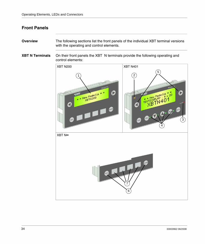
Overview The following sections list the front panels of the individual XBT terminal versions with the operating and control elements.
XBT N Terminals On their front panels the XBT N terminals provide the following operating and control elements:
XBT N200 XBT N401
XBT N••
15
3
2
4
6
7
34 33003962 06/2008

Operating Elements, LEDs and Connectors
No. Description
1 Backlit LCD display
2 Communication LED (XBT N401)
3 Alarm LED (XBT N401)
4 LEDs that can be controlled by the PLC (XBT N401)
5 Service keys for functional link
6 Service keys
7 Keys for function or numeric input (according to software configuration)
33003962 06/2008 35
Operating Elements, LEDs and Connectors
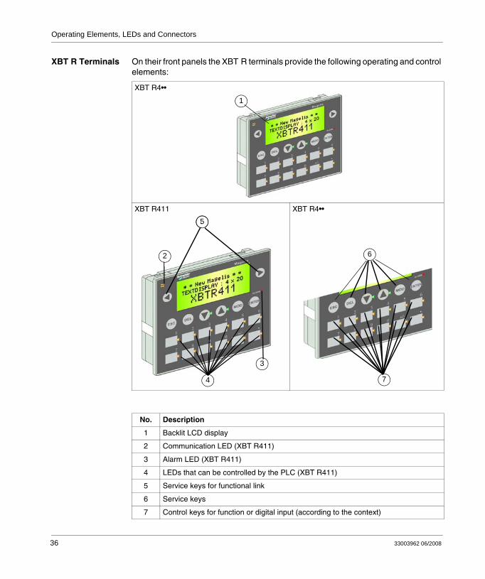
XBT R Terminals On their front panels the XBT R terminals provide the following operating and control elements:
XBT R4••
XBT R411 XBT R4••
No. Description
1 Backlit LCD display
2 Communication LED (XBT R411)
3 Alarm LED (XBT R411)
4 LEDs that can be controlled by the PLC (XBT R411)
5 Service keys for functional link
6 Service keys
7 Control keys for function or digital input (according to the context)
1
35
3
4
2 86
7
36 33003962 06/2008
Operating Elements, LEDs and Connectors
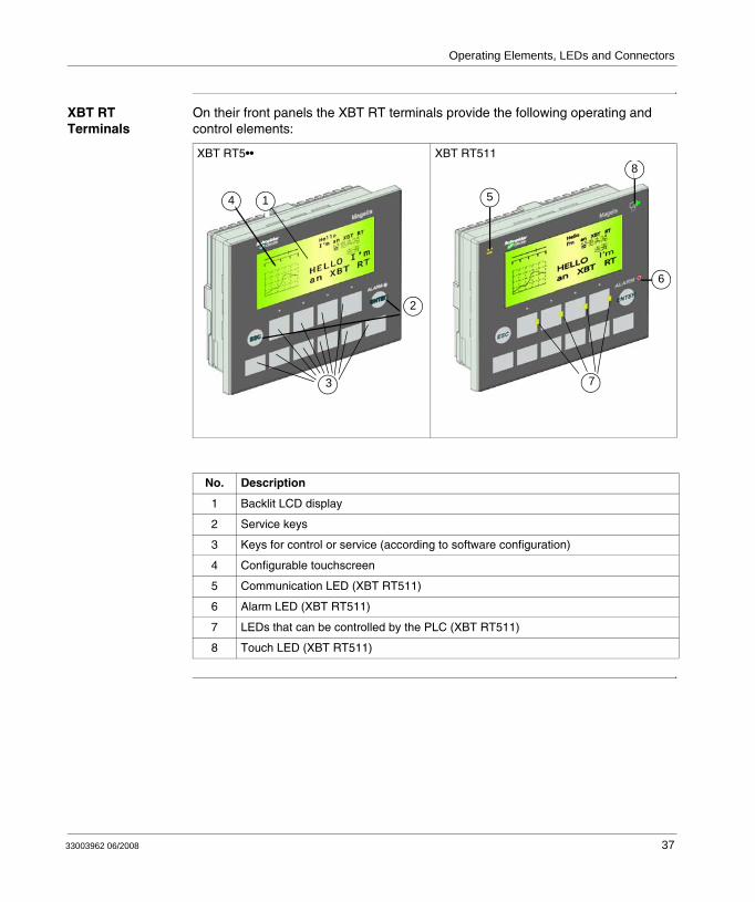
XBT RT Terminals
On their front panels the XBT RT terminals provide the following operating and control elements:
XBT RT5•• XBT RT511
No. Description
1 Backlit LCD display
2 Service keys
3 Keys for control or service (according to software configuration)
4 Configurable touchscreen
5 Communication LED (XBT RT511)
6 Alarm LED (XBT RT511)
7 LEDs that can be controlled by the PLC (XBT RT511)
8 Touch LED (XBT RT511)
4
2
3
1 5
8
6
7
33003962 06/2008 37
Operating Elements, LEDs and Connectors
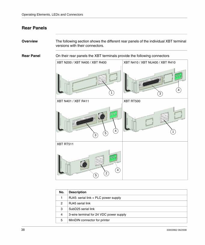
Rear Panels
Overview The following section shows the different rear panels of the individual XBT terminal versions with their connectors.
Rear Panel On their rear panels the XBT terminals provide the following connectors
XBT N200 / XBT N400 / XBT R400 XBT N410 / XBT NU400 / XBT R410
XBT N401 / XBT R411 XBT RT500
XBT RT511
No. Description
1 RJ45: serial link + PLC power supply
2 RJ45 serial link
3 SubD25 serial link
4 3-wire terminal for 24 VDC power supply
5 MiniDIN connector for printer
14
3
1 33 5
4 1
24
5
38 33003962 06/2008
Operating Elements, LEDs and Connectors
Overview of Keys on the Individual XBT Terminals
Overview The various types of XBT terminals provide different front panels including different keys for executing functions or entering values . The following paragraphs provide an overview of the keys provided on the individual XBT terminals.
Types of Keys The front panels of the terminals include 2 types of keys:
Service keysService keys provide different actions to the operator, like scrolling within the display of the terminal, selecting the panel to be displayed as well as selecting objects or entering values in the panel shown on the terminal display.Function keysFunction keys are individually configured by the HMI designer who created the HMI application of the XBT terminal using the Vijeo-Designer Lite software. 2 different types of function keys are available:
static function keys: Static function keys are assigned a constant function (like selecting the panel to be displayed or executing commands) for the entire HMI application.dynamic function keys: Dynamic function keys can be assigned different functions (like selecting the panel to be displayed, setting/resetting bits or executing commands) by the HMI designer, depending on the actually displayed panel.
XBT N and XBT RT terminals can be configured for different variants (control and input variant as well as touch variant only for XBT RT) with the function keys providing different functions in each variant. XBT R terminals, on the other hand, only provide one variant.It is also possible that function keys have different functions in one variant, depending on whether you are only viewing the panels (normal mode) or you are entering values (edition mode). Function keys with 2 functions are referred to as dual labelled keys in this manual.
UNINTENDED EQUIPMENT OPERATIONThe control key insert label must match the configured function of the key.
Failure to follow these instructions can result in death, serious injury, or equipment damage.
WARNING
33003962 06/2008 39
Operating Elements, LEDs and Connectors
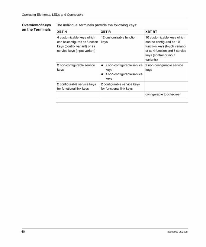
Overview of Keys on the Terminals
The individual terminals provide the following keys:
XBT N XBT R XBT RT
4 customizable keys which can be configured as function keys (control variant) or as service keys (input variant)
12 customizable function keys
10 customizable keys which can be configured as 10 function keys (touch variant) or as 4 function and 6 service keys (control or input variants)
2 non-configurable service keys
2 non-configurable service keys4 non-configurable service keys
2 non-configurable service keys
2 configurable service keys for functional link keys
2 configurable service keys for functional link keys
configurable touchscreen
40 33003962 06/2008
Operating Elements, LEDs and Connectors
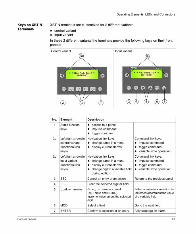
Keys on XBT N Terminals
XBT N terminals are customized for 2 different variants:
control variantinput variant
In these 2 different variants the terminals provide the following keys on their front panels:
Control variant Input variant
No. Element Description
1 Static function keys
access to a panelimpulse commandtoggle command
2a Left/right arrows in control variant (functional link keys)
Navigation link keys:change panel in a menudisplay current alarms
Command link keys:impulse commandtoggle commandvariable write operation
2b Left/right arrows in input variant (functional link keys)
Navigation link keys:change panel in a menudisplay current alarmschange digit in a variable field during edition
Command link keys:impulse commandtoggle commandvariable write operation
3 ESC Cancel an entry or an action Return to the previous panel
4 DEL Clear the selected digit or field
5 Up/down arrows Go up, go down in a panel (XBT N40• and NU400)Increment/decrement the selected digit
Select a value in a selection listIncrement/decrement the value of a variable field
6 MOD Select a field Go to the next field
7 ENTER Confirm a selection or an entry Acknowledge an alarm
2a
713
2b2b
3 4 5 6 7
DEL MOD
33003962 06/2008 41
Operating Elements, LEDs and Connectors
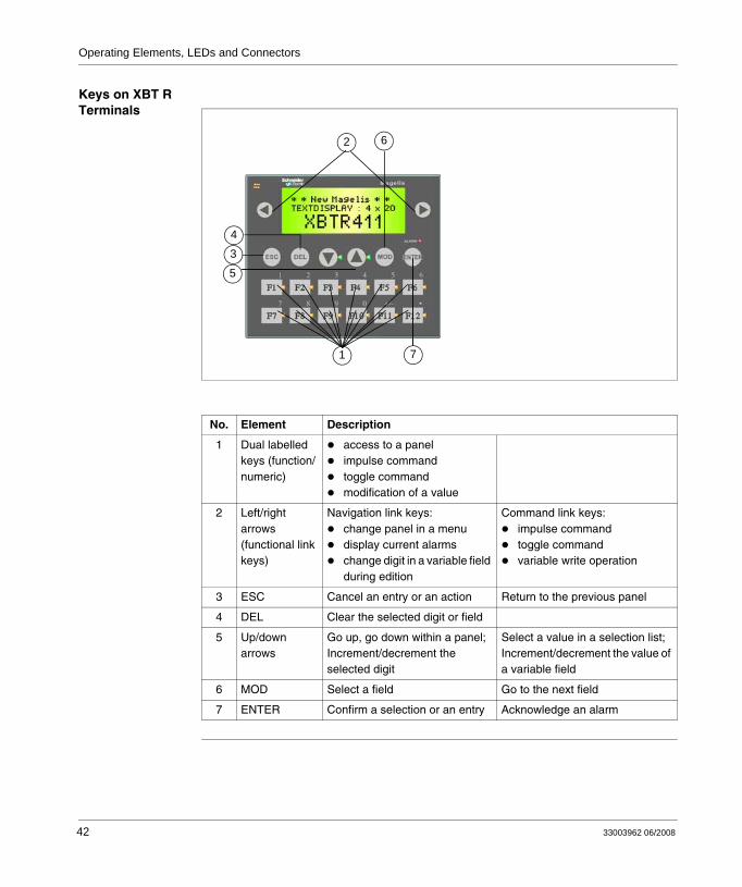
Keys on XBT R Terminals
No. Element Description
1 Dual labelled keys (function/numeric)
access to a panelimpulse commandtoggle command modification of a value
2 Left/right arrows (functional link keys)
Navigation link keys:change panel in a menudisplay current alarmschange digit in a variable field during edition
Command link keys:impulse commandtoggle commandvariable write operation
3 ESC Cancel an entry or an action Return to the previous panel
4 DEL Clear the selected digit or field
5 Up/down arrows
Go up, go down within a panel;Increment/decrement the selected digit
Select a value in a selection list;Increment/decrement the value of a variable field
6 MOD Select a field Go to the next field
7 ENTER Confirm a selection or an entry Acknowledge an alarm
62
71
4
3
5
42 33003962 06/2008
Operating Elements, LEDs and Connectors
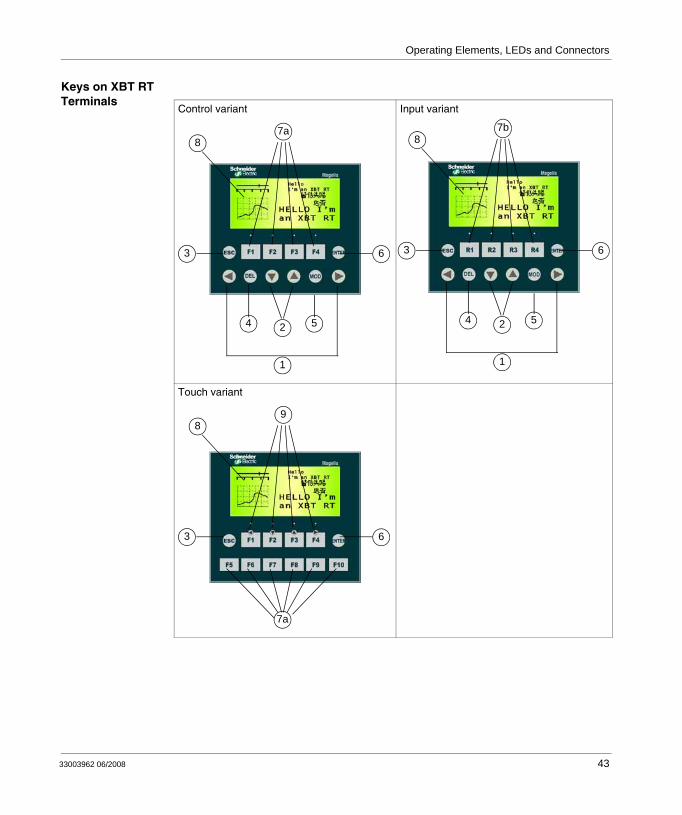
Keys on XBT RT Terminals
Control variant Input variant
Touch variant
54 2
1
3 6
7a8
54 2
1
3 6
7b8
7a
3 6
98
33003962 06/2008 43

Operating Elements, LEDs and Connectors
No. Element Description
1 Left/right arrows (functional link keys)
Navigation link keys:navigation: change panel in a menudisplay current alarmschange digit in a variable field during edition
Command link keys:impulse commandtoggle commandvariable write operation
2 Up/down arrows
Select a functional link in a panelIncrement/decrement the selected digit
Select a value in a selection listIncrement/decrement the value of a variable field
3 ESC Cancel an entry or an action Return to the previous panel
4 DEL Clear the selected digit or field
5 MOD Select a field Go to the next field
6 ENTER Confirm a selection or an entered value
Acknowledge an alarm
7a Control or touch variant
Static function keys:access a panelimpulse commandtoggle command
7b Input variant Dynamic function keys (functionality is panel-dependent):
access a panelset / reset bitimpulse commandtoggle command
8 Touchscreen Activity depending on the selected variant:
enabled in touch variantdisabled in control and input variant
9 Dual labelled keys
The active function of keys F1 to F4 is determined by the selected terminal mode:
in edition mode: arrow keys acting like up/down/left/right arrowsin normal mode: static function keys (see description 7)
44 33003962 06/2008
33003962 06/2008
5
Insert LabelsAt a Glance
Overview This section describes the different insert labels provided for the different XBT types and gives instructions on how to properly install them.
What's in this Chapter?
This chapter contains the following sections:
Section Topic Page
5.1 Insert Labels 47
45

Insert Labels
46 33003962 06/2008
Insert Labels
5.1 Insert Labels
At a Glance
Overview This section describes the different insert labels provided for the different XBT types.
What's in this Section?
This section contains the following topics:
Topic Page
Insert Labels XBT N 48
Insert Labels XBT R 50
Insert Labels XBT RT 52
33003962 06/2008 47
Insert Labels
Insert Labels XBT N
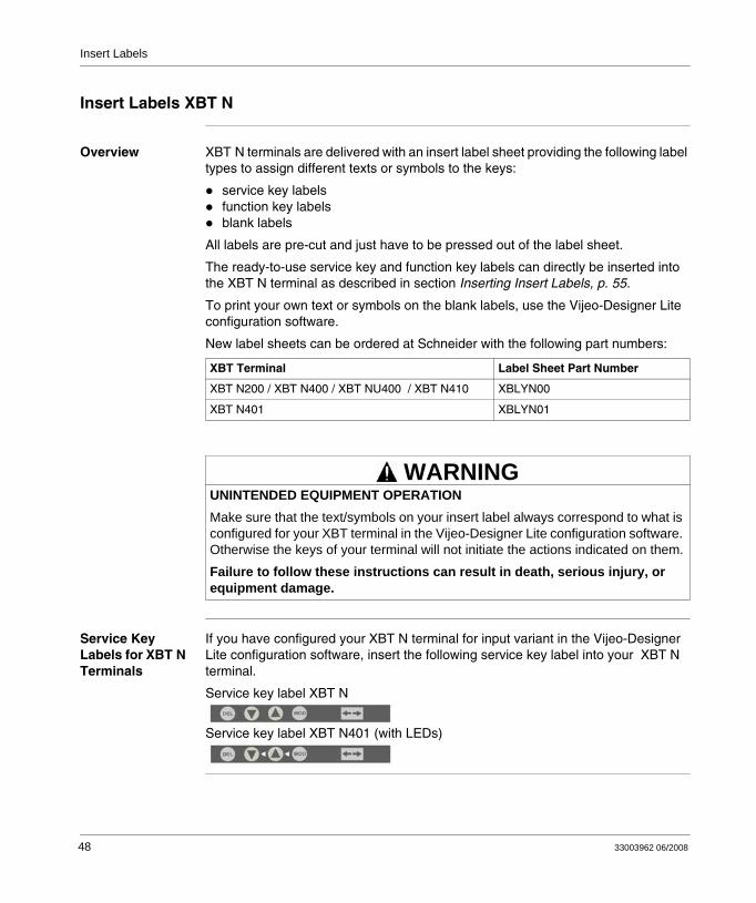
Overview XBT N terminals are delivered with an insert label sheet providing the following label types to assign different texts or symbols to the keys:
service key labelsfunction key labelsblank labels
All labels are pre-cut and just have to be pressed out of the label sheet.
The ready-to-use service key and function key labels can directly be inserted into the XBT N terminal as described in section Inserting Insert Labels, p. 55.
To print your own text or symbols on the blank labels, use the Vijeo-Designer Lite configuration software.
New label sheets can be ordered at Schneider with the following part numbers:
Service Key Labels for XBT N Terminals
If you have configured your XBT N terminal for input variant in the Vijeo-Designer Lite configuration software, insert the following service key label into your XBT N terminal.
Service key label XBT N
Service key label XBT N401 (with LEDs)
XBT Terminal Label Sheet Part Number
XBT N200 / XBT N400 / XBT NU400 / XBT N410 XBLYN00
XBT N401 XBLYN01
UNINTENDED EQUIPMENT OPERATIONMake sure that the text/symbols on your insert label always correspond to what is configured for your XBT terminal in the Vijeo-Designer Lite configuration software. Otherwise the keys of your terminal will not initiate the actions indicated on them.
Failure to follow these instructions can result in death, serious injury, or equipment damage.
WARNING
48 33003962 06/2008
Insert Labels
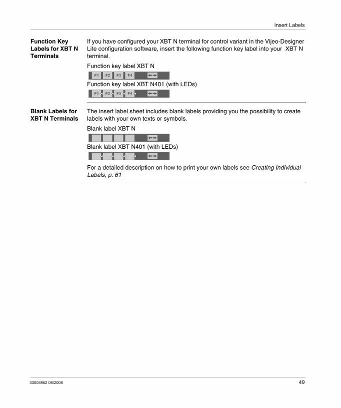
Function Key Labels for XBT N Terminals
If you have configured your XBT N terminal for control variant in the Vijeo-Designer Lite configuration software, insert the following function key label into your XBT N terminal.
Function key label XBT N
Function key label XBT N401 (with LEDs)
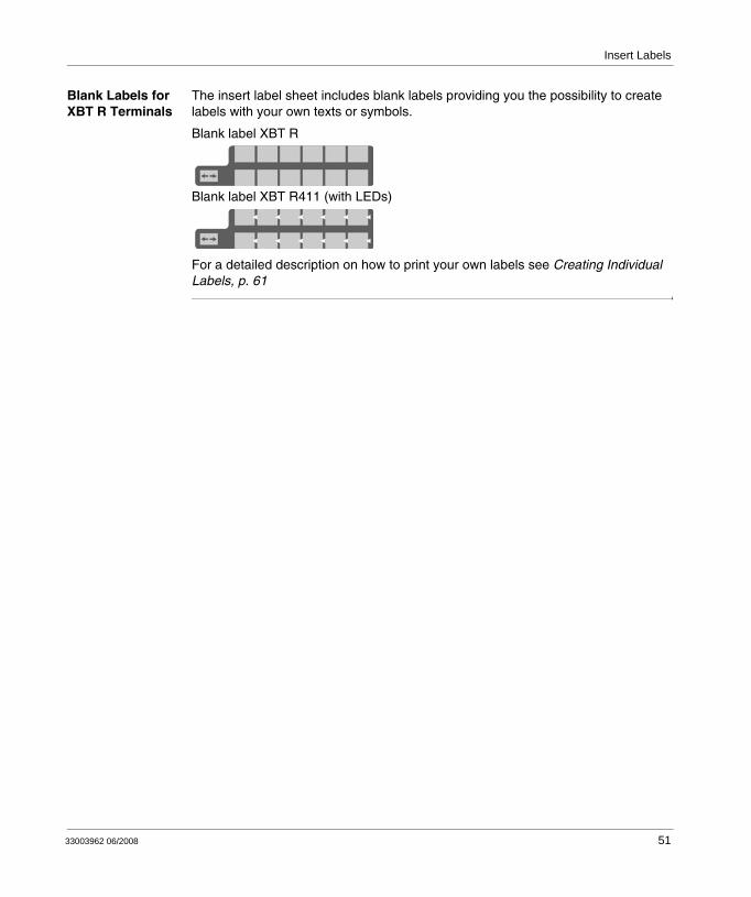
Blank Labels for XBT N Terminals
The insert label sheet includes blank labels providing you the possibility to create labels with your own texts or symbols.
Blank label XBT N
Blank label XBT N401 (with LEDs)
For a detailed description on how to print your own labels see Creating Individual Labels, p. 61
33003962 06/2008 49
Insert Labels
Insert Labels XBT R
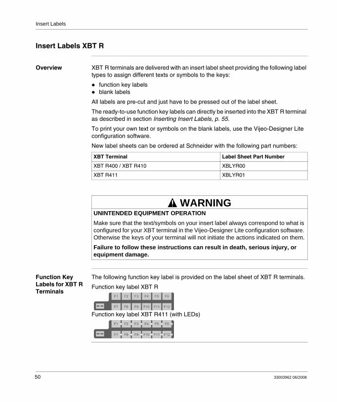
Overview XBT R terminals are delivered with an insert label sheet providing the following label types to assign different texts or symbols to the keys:
function key labelsblank labels
All labels are pre-cut and just have to be pressed out of the label sheet.
The ready-to-use function key labels can directly be inserted into the XBT R terminal as described in section Inserting Insert Labels, p. 55.
To print your own text or symbols on the blank labels, use the Vijeo-Designer Lite configuration software.
New label sheets can be ordered at Schneider with the following part numbers:
Function Key Labels for XBT R Terminals
The following function key label is provided on the label sheet of XBT R terminals.
Function key label XBT R
Function key label XBT R411 (with LEDs)
XBT Terminal Label Sheet Part Number
XBT R400 / XBT R410 XBLYR00
XBT R411 XBLYR01
UNINTENDED EQUIPMENT OPERATIONMake sure that the text/symbols on your insert label always correspond to what is configured for your XBT terminal in the Vijeo-Designer Lite configuration software. Otherwise the keys of your terminal will not initiate the actions indicated on them.
Failure to follow these instructions can result in death, serious injury, or equipment damage.
WARNING
50 33003962 06/2008
Insert Labels
Blank Labels for XBT R Terminals
The insert label sheet includes blank labels providing you the possibility to create labels with your own texts or symbols.
Blank label XBT R
Blank label XBT R411 (with LEDs)
For a detailed description on how to print your own labels see Creating Individual Labels, p. 61
33003962 06/2008 51
Insert Labels
Insert Labels XBT RT
Overview XBT RT terminals are delivered with 2 insert label sheets providing the following label types to assign different texts or symbols to the keys:
service key labelsfunction key labelstouch key labelsblank labels
All labels are pre-cut and just have to be pressed out of the label sheet.
The ready-to-use service key, function key and touch key labels can directly be inserted into the XBT RT terminal as described in section Inserting Insert Labels, p. 55.
To print your own text or symbols on the blank labels, use the Vijeo-Designer Lite configuration software.
New label sheets can be ordered at Schneider with the following part numbers:
XBT Terminal Label Sheet Part Number
XBT RT500 XBLYRT00
XBT RT511 XBLYRT01
UNINTENDED EQUIPMENT OPERATIONMake sure that the text/symbols on your insert label always correspond to what is configured for your XBT terminal in the Vijeo-Designer Lite configuration software. Otherwise the keys of your terminal will not initiate the actions indicated on them.
Failure to follow these instructions can result in death, serious injury, or equipment damage.
WARNING
52 33003962 06/2008
Insert Labels
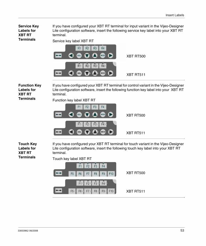
Service Key Labels for XBT RT Terminals
If you have configured your XBT RT terminal for input variant in the Vijeo-Designer Lite configuration software, insert the following service key label into your XBT RT terminal.
Service key label XBT RT
Function Key Labels for XBT RT Terminals
If you have configured your XBT RT terminal for control variant in the Vijeo-Designer Lite configuration software, insert the following function key label into your XBT RT terminal.
Function key label XBT RT
Touch Key Labels for XBT RT Terminals
If you have configured your XBT RT terminal for touch variant in the Vijeo-Designer Lite configuration software, insert the following touch key label into your XBT RT terminal.
Touch key label XBT RT
XBT RT500
XBT RT511
XBT RT500
XBT RT511
XBT RT500
XBT RT511
33003962 06/2008 53
Insert Labels
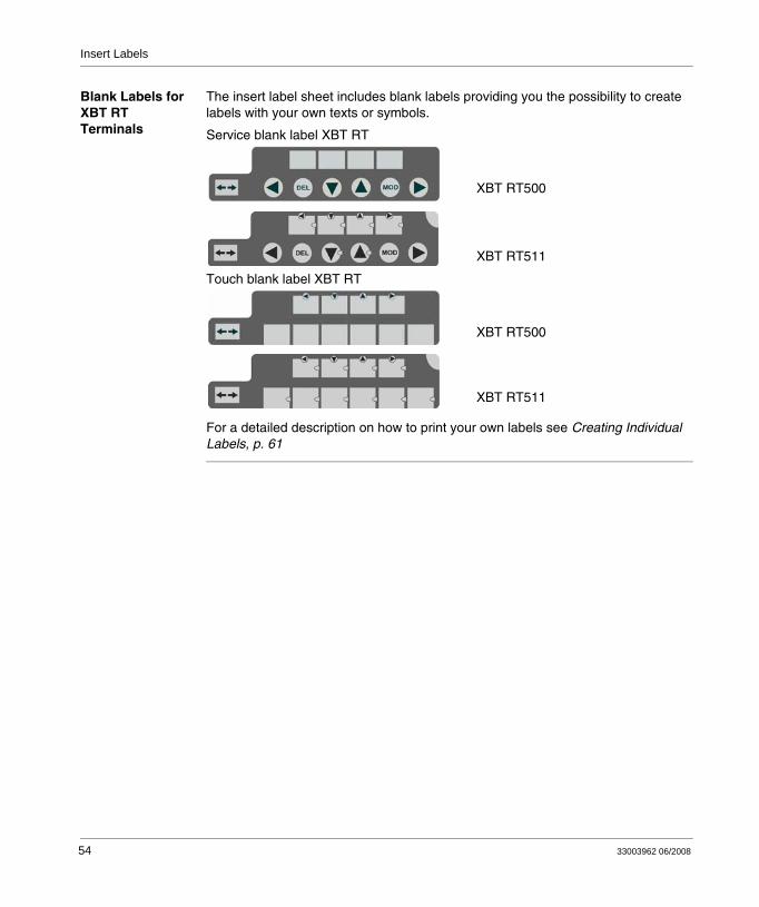
Blank Labels for XBT RT Terminals
The insert label sheet includes blank labels providing you the possibility to create labels with your own texts or symbols.
Service blank label XBT RT
Touch blank label XBT RT
For a detailed description on how to print your own labels see Creating Individual Labels, p. 61
XBT RT500
XBT RT511
XBT RT500
XBT RT511
54 33003962 06/2008
33003962 06/2008
6
Inserting LabelsInserting Insert Labels
Overview In order to be sure that each key of the XBT terminals executes the requested function it is of vital importance that you correctly insert the insert label into the device. The following paragraphs describe the procedures of inserting insert labels into XBT N, XBT R and XBT RT terminals.
UNINTENDED EQUIPMENT OPERATIONMake sure that the text/symbols on your insert label always correspond to what is configured for your XBT terminal in the Vijeo-Designer Lite configuration software. Otherwise the keys of your terminal will not initiate the actions indicated on them.
Failure to follow these instructions can result in death, serious injury, or equipment damage.
WARNING
55
Inserting Labels
Graphical Representation of Correctly Inserting Labels into XBT N Terminals
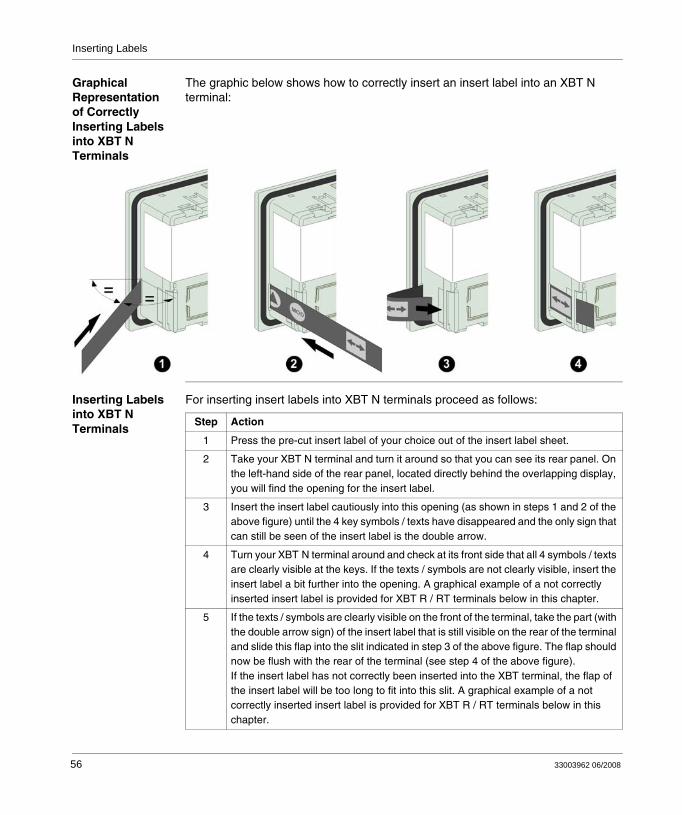
The graphic below shows how to correctly insert an insert label into an XBT N terminal:
Inserting Labels into XBT N Terminals
For inserting insert labels into XBT N terminals proceed as follows:
Step Action
1 Press the pre-cut insert label of your choice out of the insert label sheet.
2 Take your XBT N terminal and turn it around so that you can see its rear panel. On the left-hand side of the rear panel, located directly behind the overlapping display, you will find the opening for the insert label.
3 Insert the insert label cautiously into this opening (as shown in steps 1 and 2 of the above figure) until the 4 key symbols / texts have disappeared and the only sign that can still be seen of the insert label is the double arrow.
4 Turn your XBT N terminal around and check at its front side that all 4 symbols / texts are clearly visible at the keys. If the texts / symbols are not clearly visible, insert the insert label a bit further into the opening. A graphical example of a not correctly inserted insert label is provided for XBT R / RT terminals below in this chapter.
5 If the texts / symbols are clearly visible on the front of the terminal, take the part (with the double arrow sign) of the insert label that is still visible on the rear of the terminal and slide this flap into the slit indicated in step 3 of the above figure. The flap should now be flush with the rear of the terminal (see step 4 of the above figure). If the insert label has not correctly been inserted into the XBT terminal, the flap of the insert label will be too long to fit into this slit. A graphical example of a not correctly inserted insert label is provided for XBT R / RT terminals below in this chapter.
56 33003962 06/2008

Inserting Labels
Graphical Representation of Correctly Inserting Labels into XBT R / XBT RT Terminals
The graphic below shows how to correctly insert an insert label into an XBT R / XBT RT terminal:
33003962 06/2008 57
Inserting Labels
Inserting Labels into XBT R / XBT RT Terminals
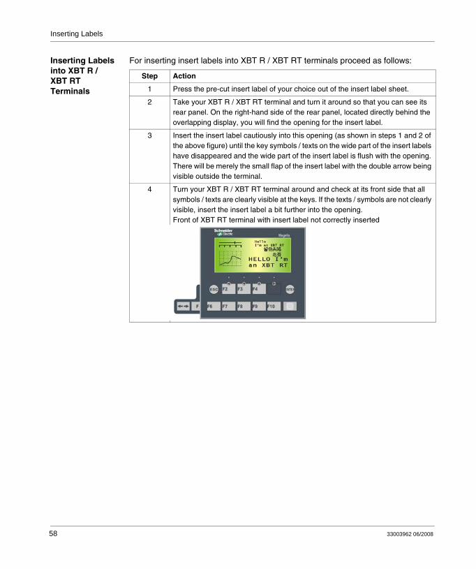
For inserting insert labels into XBT R / XBT RT terminals proceed as follows:
Step Action
1 Press the pre-cut insert label of your choice out of the insert label sheet.
2 Take your XBT R / XBT RT terminal and turn it around so that you can see its rear panel. On the right-hand side of the rear panel, located directly behind the overlapping display, you will find the opening for the insert label.
3 Insert the insert label cautiously into this opening (as shown in steps 1 and 2 of the above figure) until the key symbols / texts on the wide part of the insert labels have disappeared and the wide part of the insert label is flush with the opening. There will be merely the small flap of the insert label with the double arrow being visible outside the terminal.
4 Turn your XBT R / XBT RT terminal around and check at its front side that all symbols / texts are clearly visible at the keys. If the texts / symbols are not clearly visible, insert the insert label a bit further into the opening.Front of XBT RT terminal with insert label not correctly inserted
58 33003962 06/2008
Inserting Labels
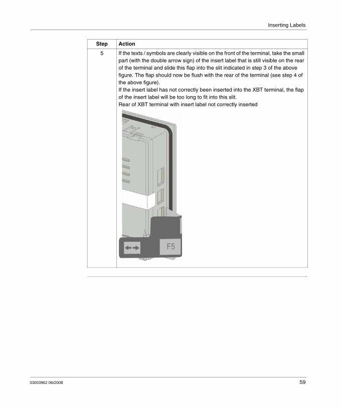
5 If the texts / symbols are clearly visible on the front of the terminal, take the small part (with the double arrow sign) of the insert label that is still visible on the rear of the terminal and slide this flap into the slit indicated in step 3 of the above figure. The flap should now be flush with the rear of the terminal (see step 4 of the above figure).If the insert label has not correctly been inserted into the XBT terminal, the flap of the insert label will be too long to fit into this slit.Rear of XBT terminal with insert label not correctly inserted
Step Action
33003962 06/2008 59

Inserting Labels
60 33003962 06/2008
33003962 06/2008
7
Creating Individual LabelsCreating Individual Labels
Overview For describing the procedure of creating and printing individual texts or symbols on the blank labels, blank labels of XBT R / RT terminals are used as an example in this section. The process of printing labels for XBT N terminals is identical, with the difference that they provide only 1 line of text / symbols.
61
Creating Individual Labels
Creating Individual Labels
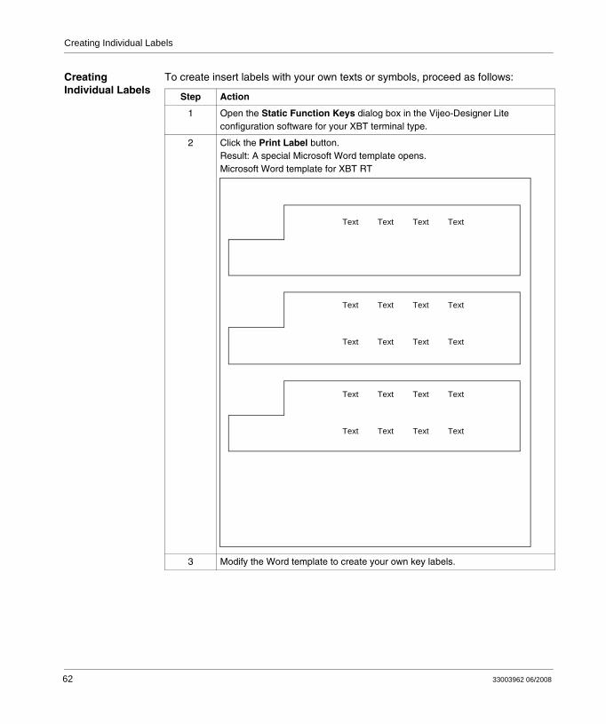
To create insert labels with your own texts or symbols, proceed as follows:
Step Action
1 Open the Static Function Keys dialog box in the Vijeo-Designer Lite configuration software for your XBT terminal type.
2 Click the Print Label button.Result: A special Microsoft Word template opens.Microsoft Word template for XBT RT
3 Modify the Word template to create your own key labels.
Text Text
Text
Text Text
Text
TextText Text
TextText Text
Text
Text
TextText Text
TextText Text
62 33003962 06/2008
Creating Individual Labels
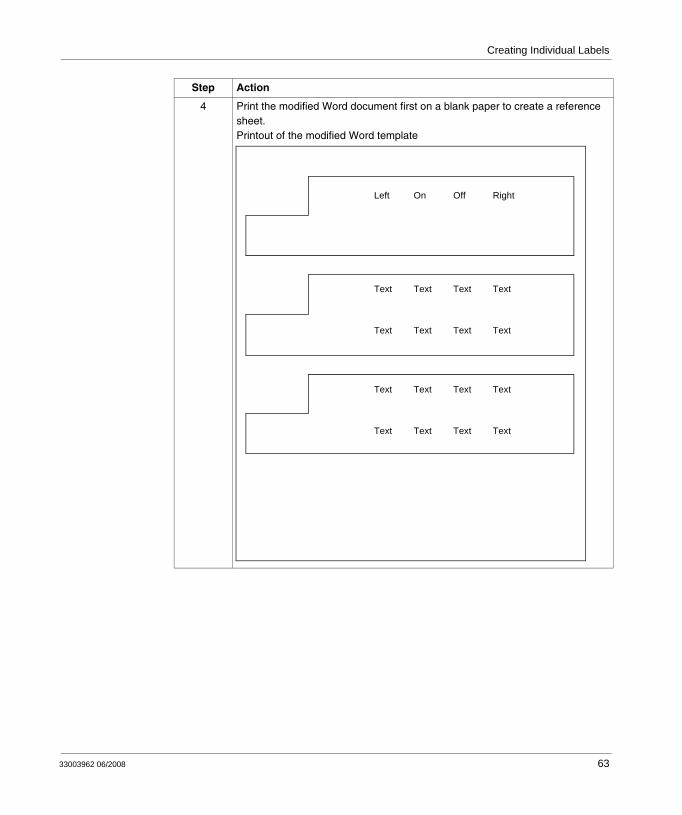
4 Print the modified Word document first on a blank paper to create a reference sheet.Printout of the modified Word template
Step Action
Left Off
Text
On Right
Text
TextText Text
TextText Text
Text
Text
TextText Text
TextText Text
33003962 06/2008 63
Creating Individual Labels
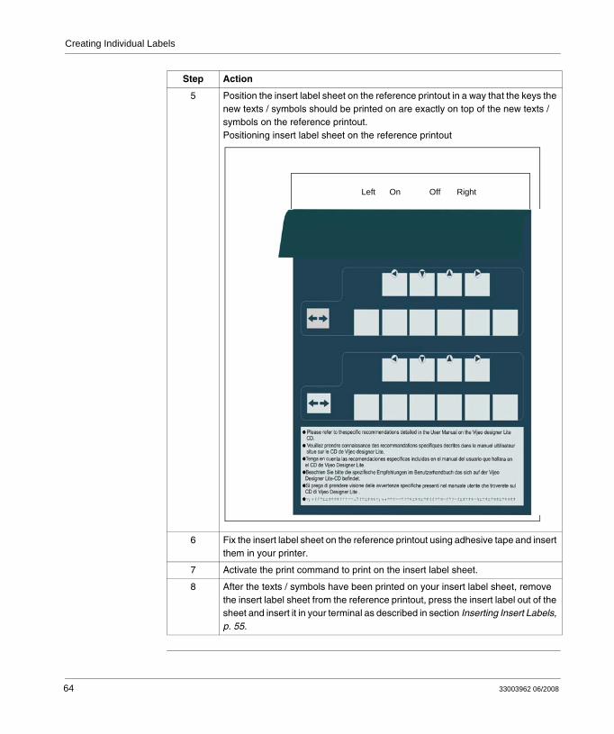
5 Position the insert label sheet on the reference printout in a way that the keys the new texts / symbols should be printed on are exactly on top of the new texts / symbols on the reference printout.Positioning insert label sheet on the reference printout
6 Fix the insert label sheet on the reference printout using adhesive tape and insert them in your printer.
7 Activate the print command to print on the insert label sheet.
8 After the texts / symbols have been printed on your insert label sheet, remove the insert label sheet from the reference printout, press the insert label out of the sheet and insert it in your terminal as described in section Inserting Insert Labels, p. 55.
Step Action
Left On Off Right
64 33003962 06/2008
33003962 06/2008
8
Connecting XBT TerminalsAt a Glance
Overview XBT terminals can be connected to different equipment to perform the following tasks:
For exchanging software configuration data with Vijeo-Designer Lite, connect the XBT terminal with a PC where Vijeo-Designer Lite is running.For controlling an automation system, connect the XBT terminal with a PLC.For printing alarms as a data stream, alarm log files or a list of current alarms, connect the XBT terminal with a printer.
The following sections describe how to connect your XBT terminal to the different equipment and provides safety information concerning the cabling.
What's in this Chapter?
This chapter contains the following sections:
Section Topic Page
8.1 Grounding and Safety 67
8.2 Connecting XBT Terminals to a PC 69
8.3 Connecting XBT Terminals to a PLC 77
8.4 Connecting XBT N401 / R411 / RT511 Terminals to a Printer 89
65

Connecting XBT Terminals
66 33003962 06/2008

Connecting XBT Terminals
8.1 Grounding and Safety
Safety Information Concerning the Grounding of Terminals
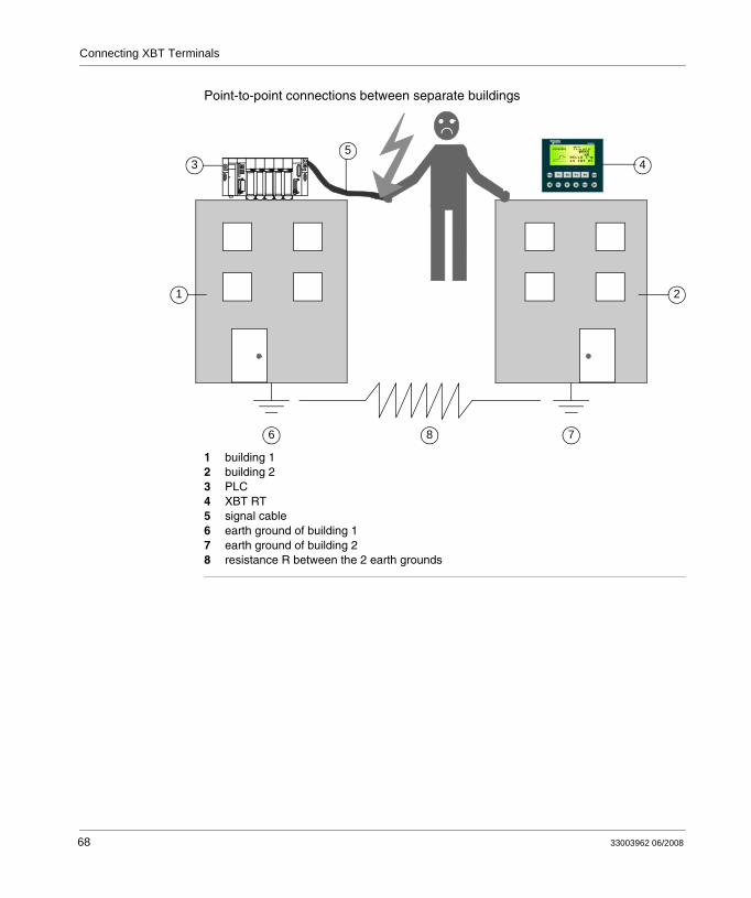
Danger of Point-to-Point Connections Between Separate Buildings
Care must be taken when XBT terminals are directly connected to a PLC that is located in another building. When you remove the cable from the terminal, you will loose the protective earth ground of the terminal. Since these 2 buildings can have different earth grounds, unplugging the cable from the terminal can lead to an electric shock created by a ground loop (voltage potential difference between two separate buildings).
HAZARD OF ELECTRIC SHOCK DUE TO IMPROPER GROUNDING
Remove power before installing or maintaining equipment.Ensure the equipment is properly grounded to the service entrance of the building.
Failure to follow these instructions will result in death or serious injury.
DANGER
33003962 06/2008 67
Connecting XBT Terminals
Point-to-point connections between separate buildings
1 building 12 building 23 PLC4 XBT RT5 signal cable6 earth ground of building 17 earth ground of building 28 resistance R between the 2 earth grounds
35
1 2
6 78
4
68 33003962 06/2008
Connecting XBT Terminals
8.2 Connecting XBT Terminals to a PC
At a Glance
Overview The following sections provide information on how to connect XBT terminals to a PC for exchanging software configuration data.
What's in this Section?
This section contains the following topics:
Topic Page
Distinguishing XBT Terminals by Power Supply 70
Connecting XBT Terminals Powered by the PLC to a PC 71
Connecting XBT Terminals Powered by an External Power Supply to a PC 74
33003962 06/2008 69
Connecting XBT Terminals
Distinguishing XBT Terminals by Power Supply
Overview For exchanging software configuration data with Vijeo-Designer Lite, connect your XBT terminal to a PC running the Vijeo-Designer Lite configuration software.
The correct cabling depends on whether your XBT terminal is
powered by the PLCpowered by an external 24 VDC power supply
The following XBT terminals need 5 V power that must be supplied by the PC in this case:
XBT N200XBT N400XBT R400XBT RT500
The following XBT terminals need an external power supply supplying 24 VDC:
XBT N410XBT N401XBT NU400XBT R410XBT R411XBT RT511
OVERVOLTAGE DAMAGE TO EQUIPMENTMake sure to connect the following terminals only to a source providing 5 VDC.
XBT N200XBT N400XBT R400XBT RT500
Failure to follow these instructions can result in injury or equipment damage.
Note: XBT RT500 terminals are protected against accidental connection to higher voltages (up to 30 V) but the other terminal types are not and will be damaged.
CAUTION
70 33003962 06/2008

Connecting XBT Terminals
Connecting XBT Terminals Powered by the PLC to a PC
Overview The following XBT terminals need 5 V power that is usually supplied by the PLC:
XBT N200XBT N400XBT R400XBT RT500
When connecting these terminals to a PC for exchanging software configuration data with Vijeo-Designer Lite, the 5 V required by the terminal must be provided by the PC.
VOLTAGE DAMAGE TO EQUIPMENTConnect the serial link connector with power off and tighten connector screws.
Failure to follow these instructions can result in injury or equipment damage.
Note: For connecting XBT terminals to a PC use the Schneider cables described in the following sections.
CAUTION
33003962 06/2008 71
Connecting XBT Terminals
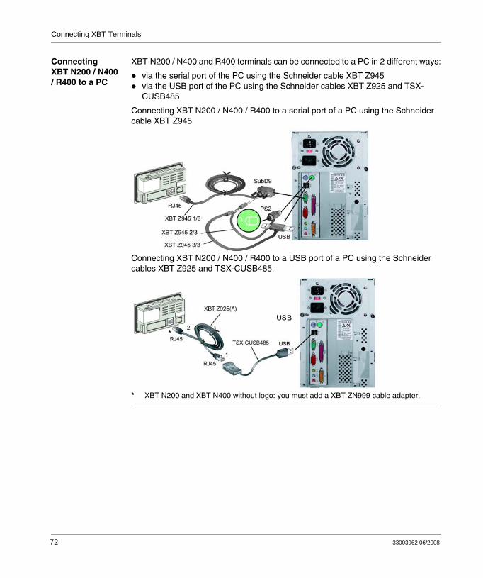
Connecting XBT N200 / N400 / R400 to a PC
XBT N200 / N400 and R400 terminals can be connected to a PC in 2 different ways:
via the serial port of the PC using the Schneider cable XBT Z945via the USB port of the PC using the Schneider cables XBT Z925 and TSX-CUSB485
Connecting XBT N200 / N400 / R400 to a serial port of a PC using the Schneider cable XBT Z945
Connecting XBT N200 / N400 / R400 to a USB port of a PC using the Schneider cables XBT Z925 and TSX-CUSB485.
* XBT N200 and XBT N400 without logo: you must add a XBT ZN999 cable adapter.
*
72 33003962 06/2008
Connecting XBT Terminals
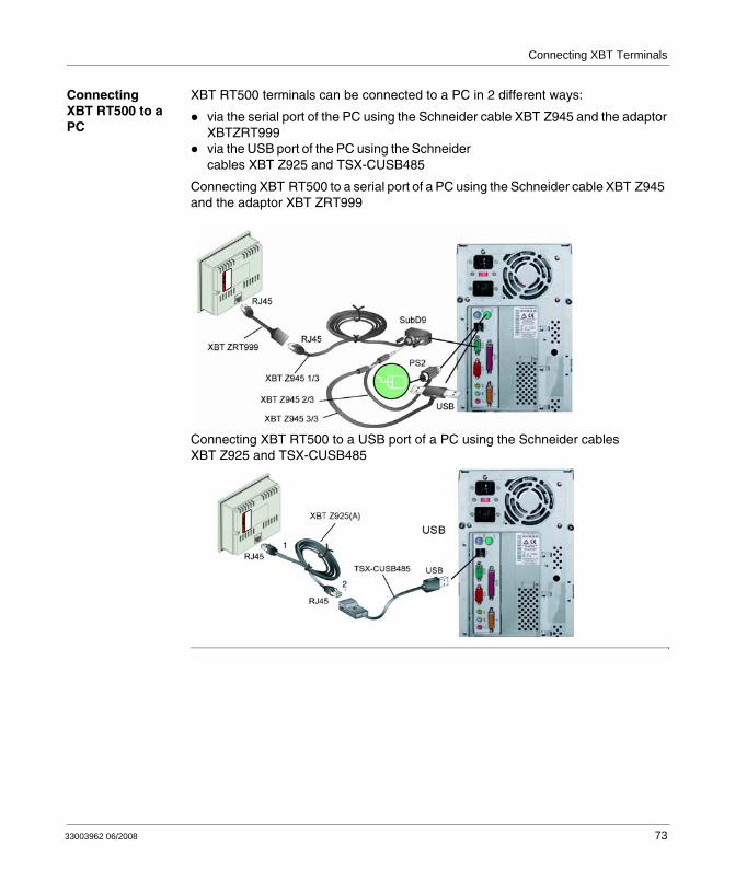
Connecting XBT RT500 to a PC
XBT RT500 terminals can be connected to a PC in 2 different ways:
via the serial port of the PC using the Schneider cable XBT Z945 and the adaptor XBTZRT999via the USB port of the PC using the Schneider cables XBT Z925 and TSX-CUSB485
Connecting XBT RT500 to a serial port of a PC using the Schneider cable XBT Z945 and the adaptor XBT ZRT999
Connecting XBT RT500 to a USB port of a PC using the Schneider cables XBT Z925 and TSX-CUSB485
WARNI
NG
1
2
WARNI
NG
33003962 06/2008 73
Connecting XBT Terminals
Connecting XBT Terminals Powered by an External Power Supply to a PC
Overview The following XBT terminals need an external power supply supplying 24 VDC:
XBT N410XBT N401XBT NU400XBT R410XBT R411XBT RT511
When connecting these terminals to a PC for exchanging software configuration data with Vijeo-Designer Lite it is also required to connect an external power supply via the 24 VDC power supply connector that is included in the scope of delivery of these XBT terminals.
VOLTAGE DAMAGE TO EQUIPMENTConnect the serial link connector with power off and tighten connector screws.
Failure to follow these instructions can result in injury or equipment damage.
Note: For connecting these XBT terminals to a PC use the Schneider cables described in the following sections.
CAUTION
74 33003962 06/2008
Connecting XBT Terminals
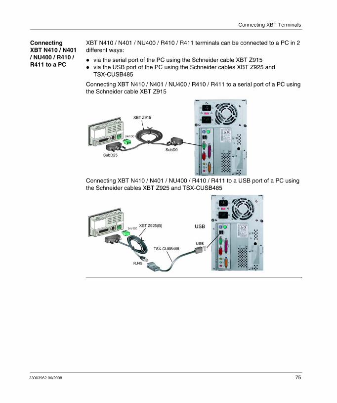
Connecting XBT N410 / N401 / NU400 / R410 / R411 to a PC
XBT N410 / N401 / NU400 / R410 / R411 terminals can be connected to a PC in 2 different ways:
via the serial port of the PC using the Schneider cable XBT Z915via the USB port of the PC using the Schneider cables XBT Z925 and TSX-CUSB485
Connecting XBT N410 / N401 / NU400 / R410 / R411 to a serial port of a PC using the Schneider cable XBT Z915
Connecting XBT N410 / N401 / NU400 / R410 / R411 to a USB port of a PC using the Schneider cables XBT Z925 and TSX-CUSB485
33003962 06/2008 75
Connecting XBT Terminals
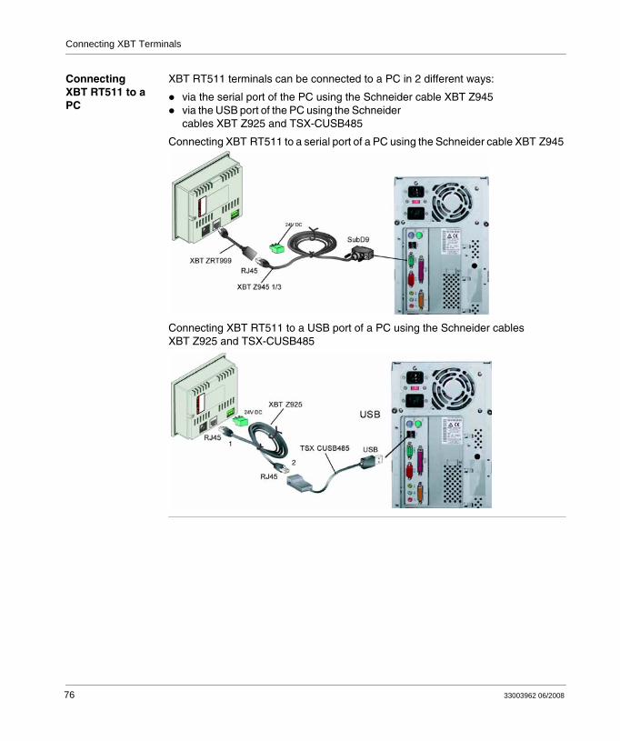
Connecting XBT RT511 to a PC
XBT RT511 terminals can be connected to a PC in 2 different ways:
via the serial port of the PC using the Schneider cable XBT Z945via the USB port of the PC using the Schneider cables XBT Z925 and TSX-CUSB485
Connecting XBT RT511 to a serial port of a PC using the Schneider cable XBT Z945
Connecting XBT RT511 to a USB port of a PC using the Schneider cables XBT Z925 and TSX-CUSB485
WARNI
NG
2
1
WARNI
NG
76 33003962 06/2008
Connecting XBT Terminals
8.3 Connecting XBT Terminals to a PLC
At a Glance
Overview The following sections provide information on how to connect XBT terminals to a PLC for controlling an automation system.
What's in this Section?
This section contains the following topics:
Topic Page
Distinguishing XBT Terminals by Power Supply 78
Connecting XBT Terminals Powered by the PLC to a PLC 80
Connecting XBT Terminals Powered by an External Power Supply to a PLC 84
33003962 06/2008 77

Connecting XBT Terminals
Distinguishing XBT Terminals by Power Supply
Overview For controlling an automation system, connect your XBT terminal to a PLC.
The correct cabling depends on whether your XBT terminal is
powered by the PLCpowered by an external 24 VDC power supply
The following XBT terminals need 5 V power that must be supplied by the PLC in this case:
XBT N200XBT N400XBT R400XBT RT500
The following XBT terminals need an external power supply supplying 24 VDC:
XBT N410XBT N401XBT NU400XBT R410XBT R411XBT RT511
OVERVOLTAGE DAMAGE TO EQUIPMENTMake sure to connect the following terminals only to a source providing 5 VDC.
XBT N200XBT N400XBT R400XBT RT500
Failure to follow these instructions can result in injury or equipment damage.
Note: XBT RT500 terminals are protected against accidental connection to higher voltages (up to 30 V) but the other terminal types are not and will be damaged.
CAUTION
78 33003962 06/2008
Connecting XBT Terminals
Data Exchanged Between XBT Terminals and PLCs
Since data are continuously exchanged in a human/machine dialog between an XBT terminal and a PLC please consider the following recommendations.
Loss of communication between the terminal and the PLC can result in partial or complete loss of control of the machine.
Unplugging the PLC cable during operation may lead to the loss of requests or responses exchanged between the terminal and the PLC.
*For additional information, refer to NEMA ICS 1.1 (latest edition), Safety Guidelines for the Application, Installation, and Maintenance of Solid State Control.
UNINTENDED EQUIPMENT OPERATION
Never remove the PLC cable from the XBT terminal while operations are in progress.Check the XBT terminal connection by monitoring the communication monitoring word in the dialog table via the PLC program.
Failure to follow these instructions can result in death, serious injury, or equipment damage.
LOSS OF CONTROL
The designer of any control scheme must consider the potential failure modes of control paths and, for certain critical functions, provide a means to achieve a safe state during and after a path failure. Examples of critical control functions are emergency stop and overtravel stop.Separate or redundant control paths must be provided for critical control functions.System control paths may include communication links. Consideration must be given to the implications of unanticipated transmission delays or failures of the link.*Each implementation of a Magelis XBT N/R/RT must be individually and thoroughly tested for proper operation before being placed into service.
Failure to follow these instructions can result in death, serious injury, or equipment damage.
WARNING
WARNING
33003962 06/2008 79
Connecting XBT Terminals
Connecting XBT Terminals Powered by the PLC to a PLC
Overview The following XBT terminals need 5 V power that is usually supplied by the PLC but may also be supplied by an external 5 VDC power supply:
XBT N200XBT N400XBT R400XBT RT500
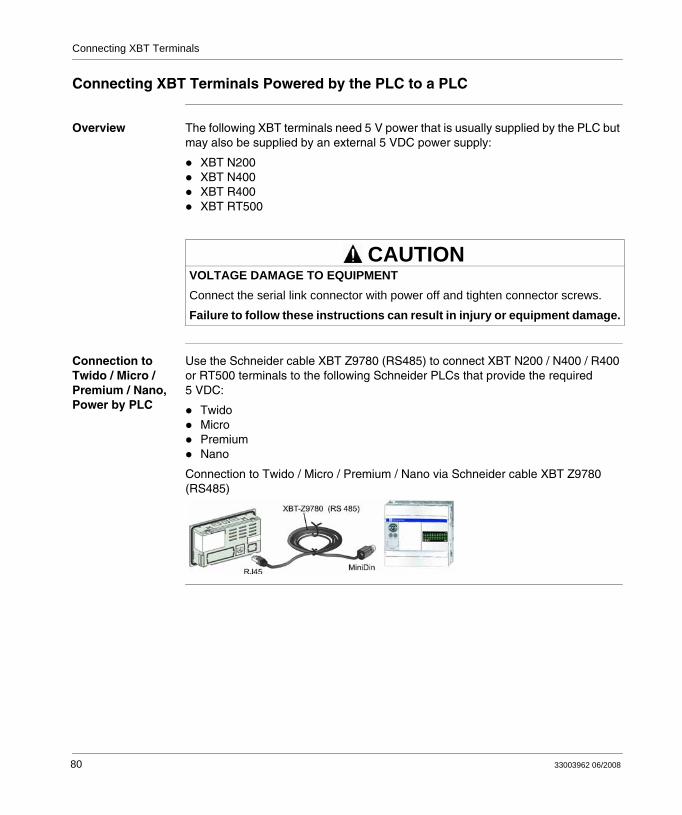
Connection to Twido / Micro / Premium / Nano, Power by PLC
Use the Schneider cable XBT Z9780 (RS485) to connect XBT N200 / N400 / R400 or RT500 terminals to the following Schneider PLCs that provide the required 5 VDC:
TwidoMicroPremiumNano
Connection to Twido / Micro / Premium / Nano via Schneider cable XBT Z9780 (RS485)
VOLTAGE DAMAGE TO EQUIPMENTConnect the serial link connector with power off and tighten connector screws.
Failure to follow these instructions can result in injury or equipment damage.
CAUTION
80 33003962 06/2008
Connecting XBT Terminals
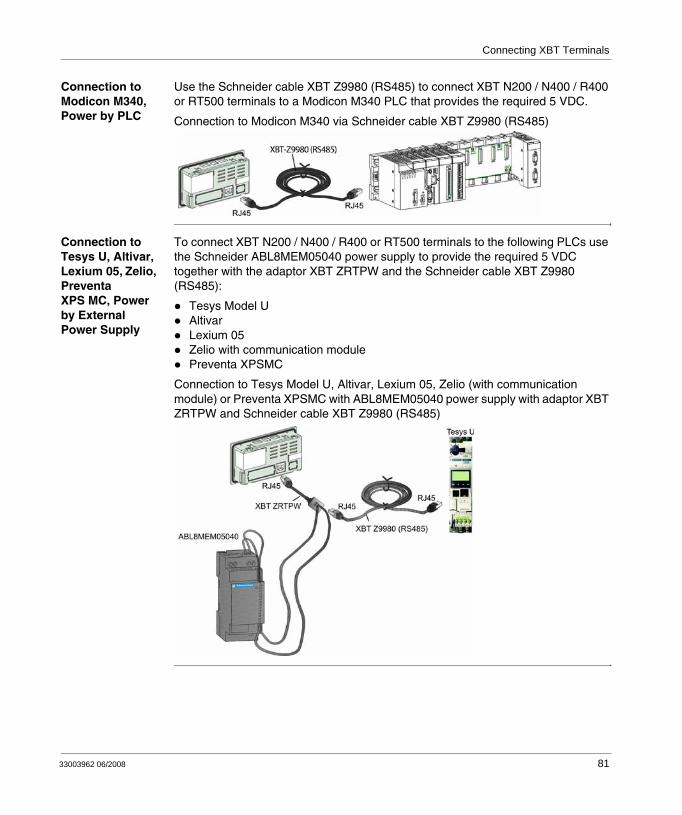
Connection to Modicon M340, Power by PLC
Use the Schneider cable XBT Z9980 (RS485) to connect XBT N200 / N400 / R400 or RT500 terminals to a Modicon M340 PLC that provides the required 5 VDC.
Connection to Modicon M340 via Schneider cable XBT Z9980 (RS485)
Connection to Tesys U, Altivar, Lexium 05, Zelio, Preventa XPS MC, Power by External Power Supply
To connect XBT N200 / N400 / R400 or RT500 terminals to the following PLCs use the Schneider ABL8MEM05040 power supply to provide the required 5 VDC together with the adaptor XBT ZRTPW and the Schneider cable XBT Z9980 (RS485):
Tesys Model UAltivarLexium 05Zelio with communication modulePreventa XPSMC
Connection to Tesys Model U, Altivar, Lexium 05, Zelio (with communication module) or Preventa XPSMC with ABL8MEM05040 power supply with adaptor XBT ZRTPW and Schneider cable XBT Z9980 (RS485)
33003962 06/2008 81
Connecting XBT Terminals
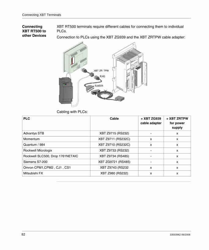
Connecting XBT RT500 to other Devices
XBT RT500 terminals require different cables for connecting them to individual PLCs.
Connection to PLCs using the XBT ZG939 and the XBT ZRTPW cable adapter:
Cabling with PLCs:
WARNI
NG
PLC Cable + XBT ZG939 cable adapter
+ XBT ZRTPW for power
supply
Advantys STB XBT Z9715 (RS232) - x
Momentum XBT Z9711 (RS232C) x x
Quantum / 984 XBT Z9710 (RS232C) x x
Rockwell Micrologix XBT Z9733 (RS232) - x
Rockwell SLC500, Drop 1761NETAIC XBT Z9734 (RS485) - x
Siemens S7-200 XBT ZG9721 (RS485) - x
Omron CPM1,CPM2 , CJ1 , CS1 XBT Z9743 (RS232 x x
Mitsubishi FX XBT Z980 (RS232) x x
82 33003962 06/2008
Connecting XBT Terminals
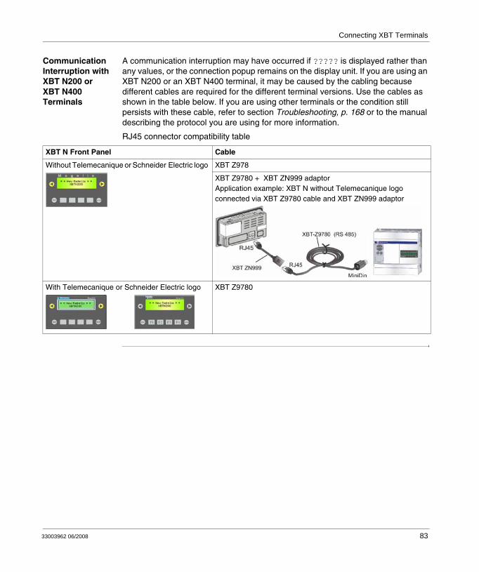
Communication Interruption with XBT N200 or XBT N400 Terminals
A communication interruption may have occurred if ????? is displayed rather than any values, or the connection popup remains on the display unit. If you are using an XBT N200 or an XBT N400 terminal, it may be caused by the cabling because different cables are required for the different terminal versions. Use the cables as shown in the table below. If you are using other terminals or the condition still persists with these cable, refer to section Troubleshooting, p. 168 or to the manual describing the protocol you are using for more information.
RJ45 connector compatibility table
XBT N Front Panel Cable
Without Telemecanique or Schneider Electric logo XBT Z978
XBT Z9780 + XBT ZN999 adaptorApplication example: XBT N without Telemecanique logo connected via XBT Z9780 cable and XBT ZN999 adaptor
With Telemecanique or Schneider Electric logo XBT Z9780
33003962 06/2008 83

Connecting XBT Terminals
Connecting XBT Terminals Powered by an External Power Supply to a PLC
Overview The following XBT terminals need an external power supply supplying 24 VDC:
XBT N410XBT N401XBT NU400XBT R410XBT R411XBT RT511
When connecting these terminals to a PLC for controlling an automation system it is also required to connect an external power supply via the 24 VDC power supply connector that is included in the scope of delivery of these XBT terminals.
VOLTAGE DAMAGE TO EQUIPMENTConnect the serial link connector with power off and tighten connector screws.
Failure to follow these instructions can result in injury or equipment damage.
Note: For connecting these XBT terminals to a PLC or a fieldbus tap use the Schneider cables described in the following sections.
CAUTION
84 33003962 06/2008
Connecting XBT Terminals
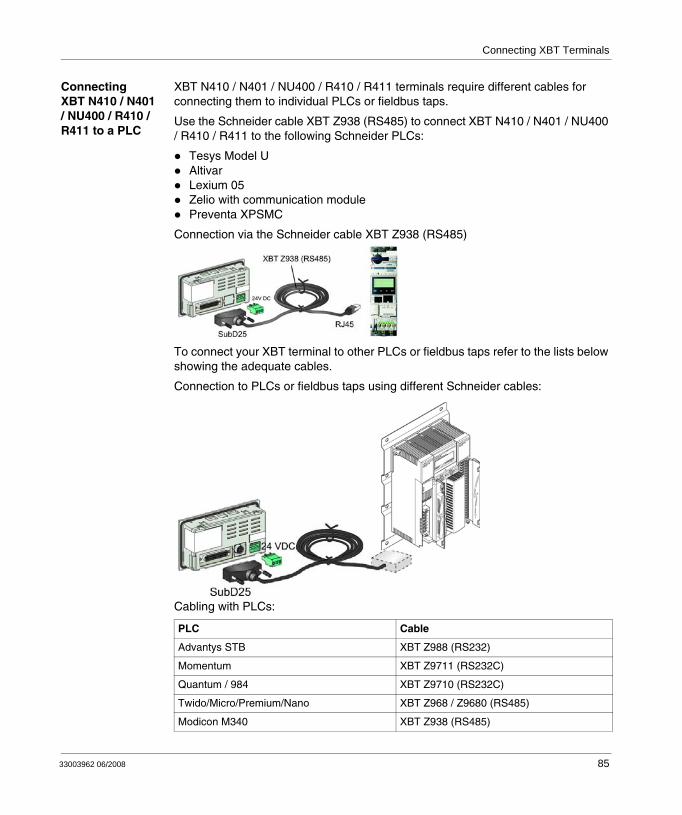
Connecting XBT N410 / N401 / NU400 / R410 / R411 to a PLC
XBT N410 / N401 / NU400 / R410 / R411 terminals require different cables for connecting them to individual PLCs or fieldbus taps.
Use the Schneider cable XBT Z938 (RS485) to connect XBT N410 / N401 / NU400 / R410 / R411 to the following Schneider PLCs:
Tesys Model UAltivarLexium 05Zelio with communication modulePreventa XPSMC
Connection via the Schneider cable XBT Z938 (RS485)
To connect your XBT terminal to other PLCs or fieldbus taps refer to the lists below showing the adequate cables.
Connection to PLCs or fieldbus taps using different Schneider cables:
Cabling with PLCs:
PLC Cable
Advantys STB XBT Z988 (RS232)
Momentum XBT Z9711 (RS232C)
Quantum / 984 XBT Z9710 (RS232C)
Twido/Micro/Premium/Nano XBT Z968 / Z9680 (RS485)
Modicon M340 XBT Z938 (RS485)
33003962 06/2008 85
Connecting XBT Terminals
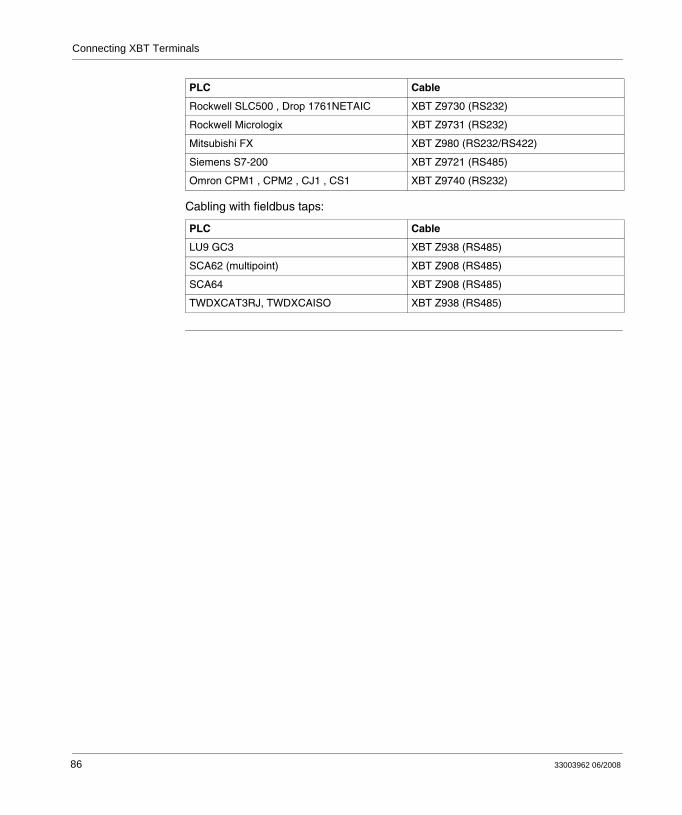
Cabling with fieldbus taps:
Rockwell SLC500 , Drop 1761NETAIC XBT Z9730 (RS232)
Rockwell Micrologix XBT Z9731 (RS232)
Mitsubishi FX XBT Z980 (RS232/RS422)
Siemens S7-200 XBT Z9721 (RS485)
Omron CPM1 , CPM2 , CJ1 , CS1 XBT Z9740 (RS232)
PLC Cable
LU9 GC3 XBT Z938 (RS485)
SCA62 (multipoint) XBT Z908 (RS485)
SCA64 XBT Z908 (RS485)
TWDXCAT3RJ, TWDXCAISO XBT Z938 (RS485)
PLC Cable
86 33003962 06/2008
Connecting XBT Terminals
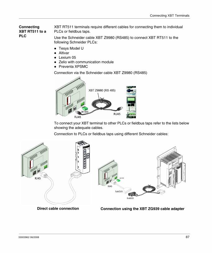
Connecting XBT RT511 to a PLC
XBT RT511 terminals require different cables for connecting them to individual PLCs or fieldbus taps.
Use the Schneider cable XBT Z9980 (RS485) to connect XBT RT511 to the following Schneider PLCs:
Tesys Model UAltivarLexium 05Zelio with communication modulePreventa XPSMC
Connection via the Schneider cable XBT Z9980 (RS485)
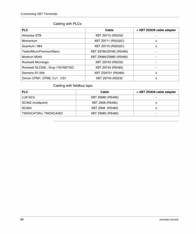
To connect your XBT terminal to other PLCs or fieldbus taps refer to the lists below showing the adequate cables.
Connection to PLCs or fieldbus taps using different Schneider cables:
WARNI
NG
Direct cable connection Connection using the XBT ZG939 cable adapter
WARNI
NG
WARNI
NG
33003962 06/2008 87
Connecting XBT Terminals
Cabling with PLCs:
Cabling with fieldbus taps:
PLC Cable + XBT ZG939 cable adapter
Advantys STB XBT Z9715 (RS232) -
Momentum XBT Z9711 (RS232C) x
Quantum / 984 XBT Z9710 (RS232C) x
Twido/Micro/Premium/Nano XBT Z9780/Z9782 (RS485) -
Modicon M340 XBT Z9980/Z9982 (RS485) -
Rockwell Micrologix XBT Z9733 (RS232) -
Rockwell SLC500 , Drop 1761NETAIC XBT Z9734 (RS485) -
Siemens S7-200 XBT ZG9721 (RS485) x
Omron CPM1, CPM2, CJ1 , CS1 XBT Z9743 (RS232 x
PLC Cable + XBT ZG939 cable adapter
LU9 GC3 XBT Z9980 (RS485) -
SCA62 (multipoint) XBT Z908 (RS485) x
SCA64 XBT Z908 (RS485) x
TWDXCAT3RJ, TWDXCAISO XBT Z9980 (RS485) -
88 33003962 06/2008
Connecting XBT Terminals
8.4 Connecting XBT N401 / R411 / RT511 Terminals to a Printer
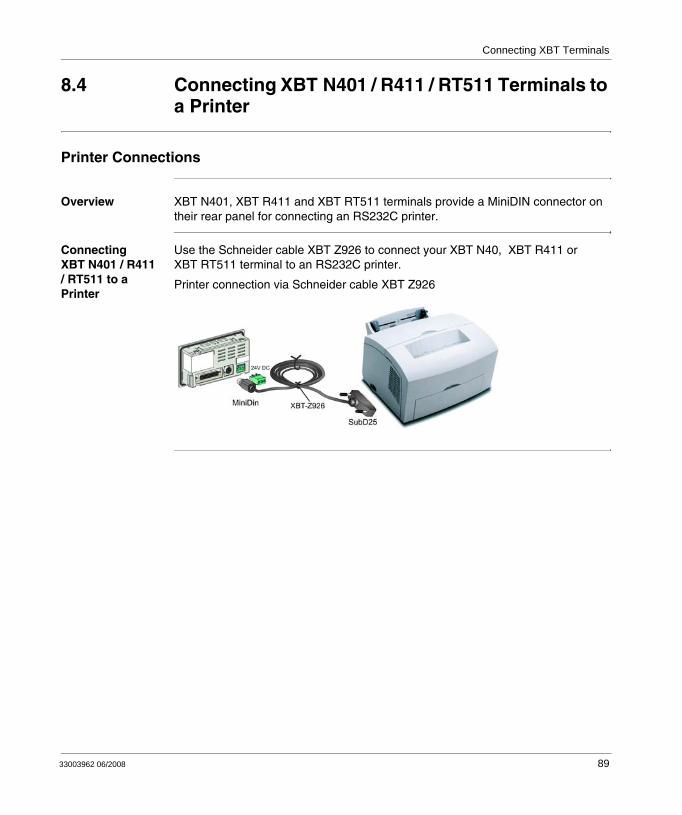
Printer Connections
Overview XBT N401, XBT R411 and XBT RT511 terminals provide a MiniDIN connector on their rear panel for connecting an RS232C printer.
Connecting XBT N401 / R411 / RT511 to a Printer
Use the Schneider cable XBT Z926 to connect your XBT N40, XBT R411 or XBT RT511 terminal to an RS232C printer.
Printer connection via Schneider cable XBT Z926
33003962 06/2008 89

Connecting XBT Terminals
90 33003962 06/2008
33003962 06/2008
9
Overview of Applications and FunctionsAt a Glance
Overview This chapter provides an overview of applications and functions of XBT terminals.
What's in this Chapter?
This chapter contains the following sections:
Section Topic Page
9.1 Overview of Functions 93
9.2 XBT Terminals in HMI Applications 94
9.3 Functions of Keys, Touchscreen, LEDs 97
91

Overview of Applications and Functions
92 33003962 06/2008
Overview of Applications and Functions
9.1 Overview of Functions
Overview of XBT Terminal Functions
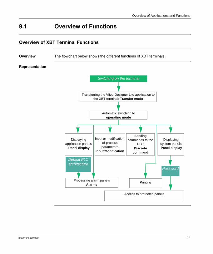
Overview The flowchart below shows the different functions of XBT terminals.
Representation
Automatic switching to operating mode
Input or modification of process parameters
Input/Modification
Password
Processing alarm panelsAlarms
Default PLC architecture
Sending commands to the
PLCDiscrete
command
Access to protected panels
Transferring the Vijeo-Designer Lite application to the XBT terminal: Transfer mode
Displaying application panels
Panel display
Displaying system panels Panel display
Switching on the terminal
Printing
33003962 06/2008 93
Overview of Applications and Functions
9.2 XBT Terminals in HMI Applications
HMI Applications
HMI Application Example
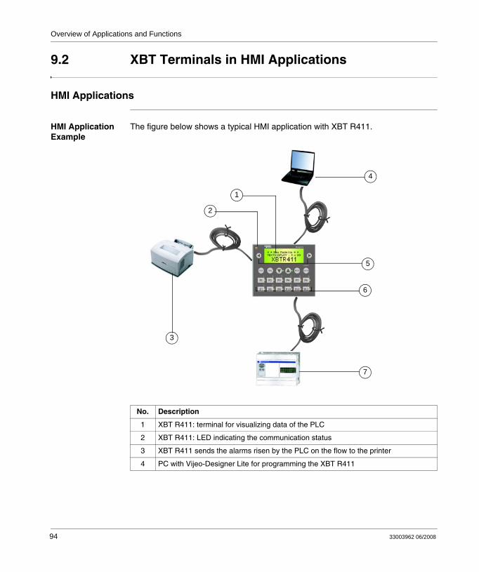
The figure below shows a typical HMI application with XBT R411.
No. Description
1 XBT R411: terminal for visualizing data of the PLC
2 XBT R411: LED indicating the communication status
3 XBT R411 sends the alarms risen by the PLC on the flow to the printer
4 PC with Vijeo-Designer Lite for programming the XBT R411
1
2
3
5
6
7
4
94 33003962 06/2008
Overview of Applications and Functions
XBT N and XBT RT terminals provide different operating variants. Depending on the selected variant the keypad is either in control variant or in input variant or in touch variant (only XBT RT). In each variant, the individual keys provide different functions (for further information see Overview of Keys on the Individual XBT Terminals, p. 39). To indicate the different functions to the user, the key labels are interchangeable. Blank labels are provided that can be filled with individual texts.
Types of HMI Applications
Applications for XBT terminals are created in the Vijeo-Designer Lite software. They can be associated with:
production monitoringpreventive maintenancecorrective maintenanceprocess control
Production Monitoring Example
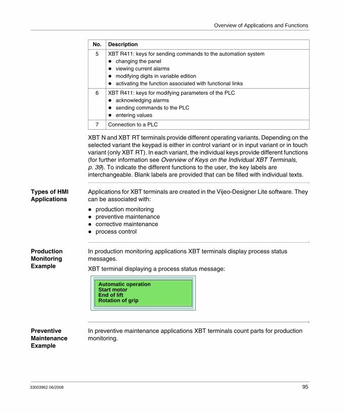
In production monitoring applications XBT terminals display process status messages.
XBT terminal displaying a process status message:
Preventive Maintenance Example
In preventive maintenance applications XBT terminals count parts for production monitoring.
5 XBT R411: keys for sending commands to the automation systemchanging the panelviewing current alarmsmodifying digits in variable editionactivating the function associated with functional links
6 XBT R411: keys for modifying parameters of the PLCacknowledging alarmssending commands to the PLCentering values
7 Connection to a PLC
No. Description
Automatic operationStart motorEnd of liftRotation of grip
33003962 06/2008 95

Overview of Applications and Functions
XBT terminal counting parts:
Corrective Maintenance Example
In corrective maintenance applications XBT terminals indicate process conditions.
XBT terminal indicating process conditions:
Process Control Example
In process control applications XBT terminals provide process control via configurable function keys.
XBT terminal providing process control via configurable function keys:
As indicated on the display unit of the XBT N in the above figure, the function pressurizing is controlled by the key named P and the function start cycle is controlled by the key named SC.
Housing: 7555Unit: 1200
Oil level lowDoor open
PF1 SC F4ESC ENTER
Magelis
Pressurizing PStart cycle SC
96 33003962 06/2008
Overview of Applications and Functions
9.3 Functions of Keys, Touchscreen, LEDs
At a Glance
Overview The following sections describe the functions of keys, touchscreen and LEDs on the different XBT terminal types.
What's in this Section?
This section contains the following topics:
Topic Page
Functions of Keys and Touchscreen 98
Functions of LEDs on XBT N401 / XBT R411 / XBT RT511 Terminals 101
33003962 06/2008 97
Overview of Applications and Functions
Functions of Keys and Touchscreen
Overview All XBT terminals provide keys on their front panels that perform different functions.
XBT R and XBT RT terminals provide specific keys, that can have 2 different functions depending on the current operating mode, the so-called dual labelled keys.
XBT RT terminals are additionally equipped with a touchscreen that allows execution of certain functions by pushing elements directly on the display unit of the terminal.
98 33003962 06/2008
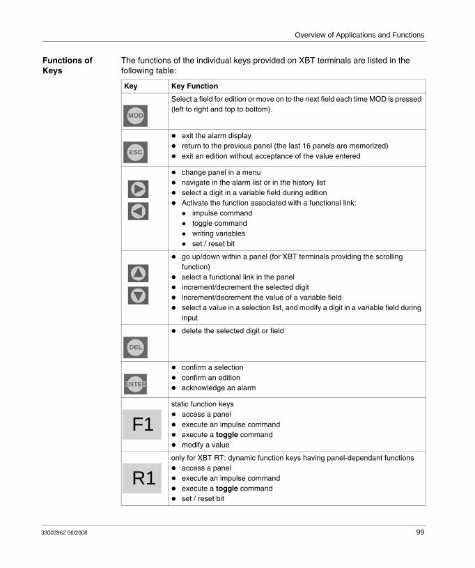
Overview of Applications and Functions
Functions of Keys
The functions of the individual keys provided on XBT terminals are listed in the following table:
Key Key Function
Select a field for edition or move on to the next field each time MOD is pressed (left to right and top to bottom).
exit the alarm displayreturn to the previous panel (the last 16 panels are memorized)exit an edition without acceptance of the value entered
change panel in a menunavigate in the alarm list or in the history listselect a digit in a variable field during editionActivate the function associated with a functional link:
impulse commandtoggle commandwriting variablesset / reset bit
go up/down within a panel (for XBT terminals providing the scrolling function)select a functional link in the panel increment/decrement the selected digitincrement/decrement the value of a variable fieldselect a value in a selection list, and modify a digit in a variable field during input
delete the selected digit or field
confirm a selectionconfirm an editionacknowledge an alarm
static function keysaccess a panelexecute an impulse commandexecute a toggle commandmodify a value
only for XBT RT: dynamic function keys having panel-dependant functionsaccess a panelexecute an impulse commandexecute a toggle commandset / reset bit
MOD
ESC
DEL
ENTER
F1
R1
33003962 06/2008 99
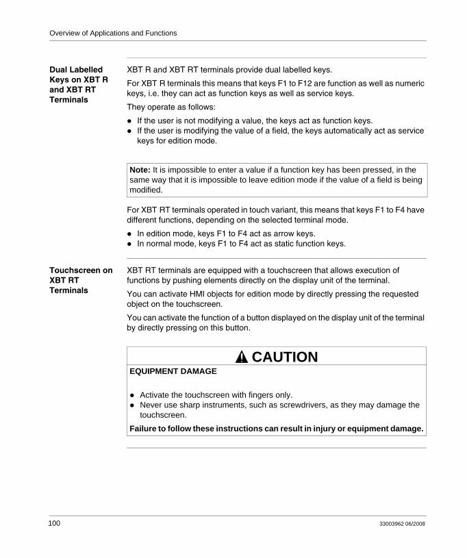
Overview of Applications and Functions
Dual Labelled Keys on XBT R and XBT RT Terminals
XBT R and XBT RT terminals provide dual labelled keys.
For XBT R terminals this means that keys F1 to F12 are function as well as numeric keys, i.e. they can act as function keys as well as service keys.
They operate as follows:
If the user is not modifying a value, the keys act as function keys.If the user is modifying the value of a field, the keys automatically act as service keys for edition mode.
For XBT RT terminals operated in touch variant, this means that keys F1 to F4 have different functions, depending on the selected terminal mode.
In edition mode, keys F1 to F4 act as arrow keys.In normal mode, keys F1 to F4 act as static function keys.
Touchscreen on XBT RT Terminals
XBT RT terminals are equipped with a touchscreen that allows execution of functions by pushing elements directly on the display unit of the terminal.
You can activate HMI objects for edition mode by directly pressing the requested object on the touchscreen.
You can activate the function of a button displayed on the display unit of the terminal by directly pressing on this button.
Note: It is impossible to enter a value if a function key has been pressed, in the same way that it is impossible to leave edition mode if the value of a field is being modified.
EQUIPMENT DAMAGE
Activate the touchscreen with fingers only.Never use sharp instruments, such as screwdrivers, as they may damage the touchscreen.
Failure to follow these instructions can result in injury or equipment damage.
CAUTION
100 33003962 06/2008
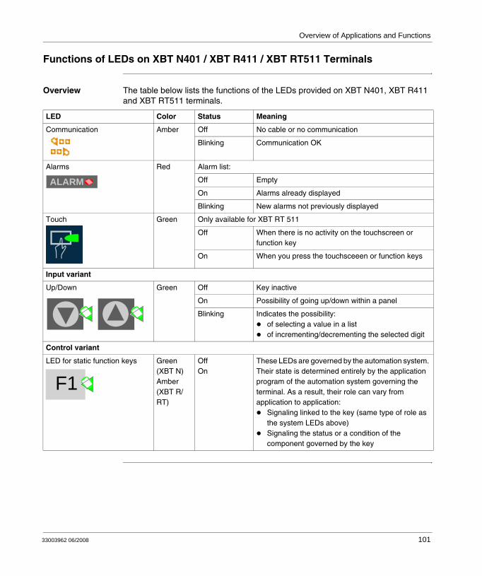
Overview of Applications and Functions
Functions of LEDs on XBT N401 / XBT R411 / XBT RT511 Terminals
Overview The table below lists the functions of the LEDs provided on XBT N401, XBT R411 and XBT RT511 terminals.
LED Color Status Meaning
Communication Amber Off No cable or no communication
Blinking Communication OK
Alarms Red Alarm list:
Off Empty
On Alarms already displayed
Blinking New alarms not previously displayed
Touch Green Only available for XBT RT 511
Off When there is no activity on the touchscreen or function key
On When you press the touchsceeen or function keys
Input variant
Up/Down Green Off Key inactive
On Possibility of going up/down within a panel
Blinking Indicates the possibility: of selecting a value in a listof incrementing/decrementing the selected digit
Control variant
LED for static function keys Green (XBT N)Amber (XBT R/RT)
OffOn
These LEDs are governed by the automation system. Their state is determined entirely by the application program of the automation system governing the terminal. As a result, their role can vary from application to application:
Signaling linked to the key (same type of role as the system LEDs above)Signaling the status or a condition of the component governed by the key
ALARM
F1
33003962 06/2008 101

Overview of Applications and Functions
102 33003962 06/2008
33003962 06/2008
10
Operating Principles of XBT TerminalsAt a Glance
Overview This sections describes general principles concerning the operation of XBT terminals.
What's in this Chapter?
This chapter contains the following sections:
Section Topic Page
10.1 Modes of Operation 105
10.2 Panel Structure of XBT Terminals 112
10.3 General Configuration Settings 125
10.4 Password-Protection 131
103

Operating Principles of XBT Terminals
104 33003962 06/2008

Operating Principles of XBT Terminals
10.1 Modes of Operation
At a Glance
Overview This section provides an overview of the 2 modes of operation of XBT terminals and describes their selection process.
What's in this Section?
This section contains the following topics:
Topic Page
Introduction 106
Automatic Selection of the Mode of Operation 107
Transfer Mode 108
Operating Mode 110
33003962 06/2008 105
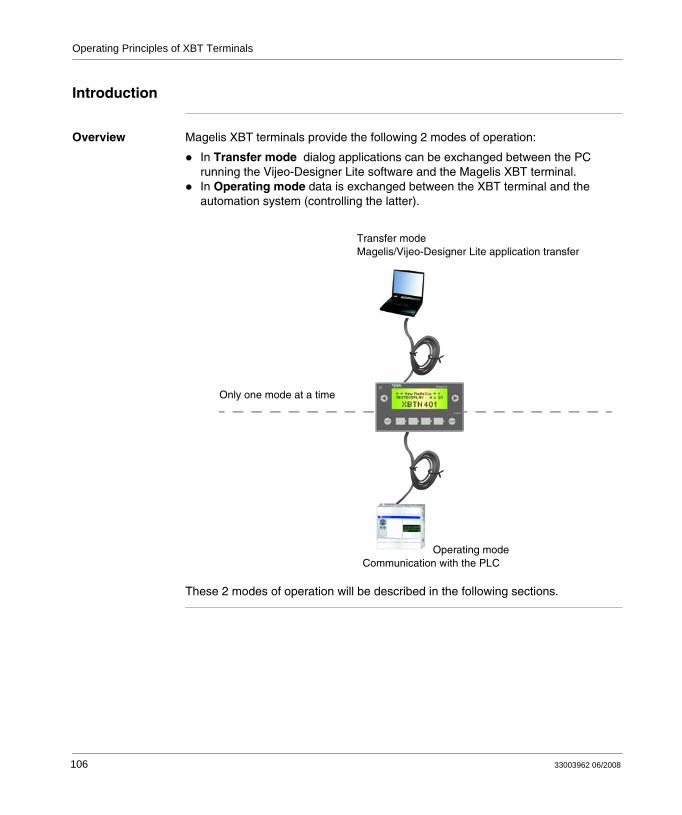
Operating Principles of XBT Terminals
Introduction
Overview Magelis XBT terminals provide the following 2 modes of operation:
In Transfer mode dialog applications can be exchanged between the PC running the Vijeo-Designer Lite software and the Magelis XBT terminal.In Operating mode data is exchanged between the XBT terminal and the automation system (controlling the latter).
These 2 modes of operation will be described in the following sections.
Only one mode at a time
Operating modeCommunication with the PLC
Transfer mode Magelis/Vijeo-Designer Lite application transfer
106 33003962 06/2008
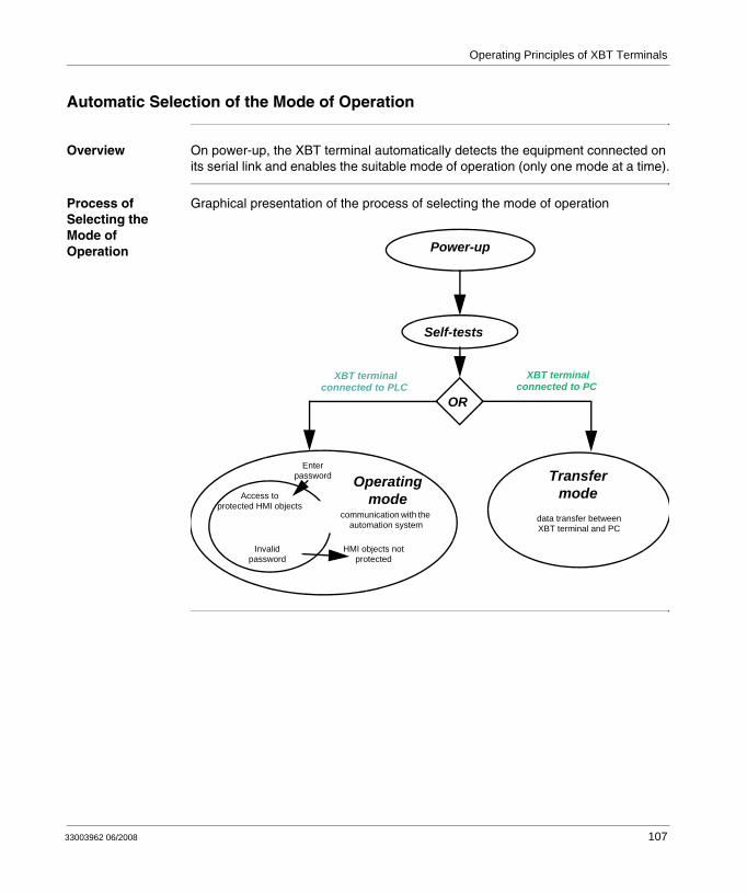
Operating Principles of XBT Terminals
Automatic Selection of the Mode of Operation
Overview On power-up, the XBT terminal automatically detects the equipment connected on its serial link and enables the suitable mode of operation (only one mode at a time).
Process of Selecting the Mode of Operation
Graphical presentation of the process of selecting the mode of operation
Invalidpassword
Access toprotected HMI objects
Power-up
Self-tests
Transfermode
XBT terminal connected to PLC
Enter password
HMI objects notprotected
XBT terminal connected to PC
data transfer between XBT terminal and PC
OR
Operating mode
communication with the automation system
33003962 06/2008 107
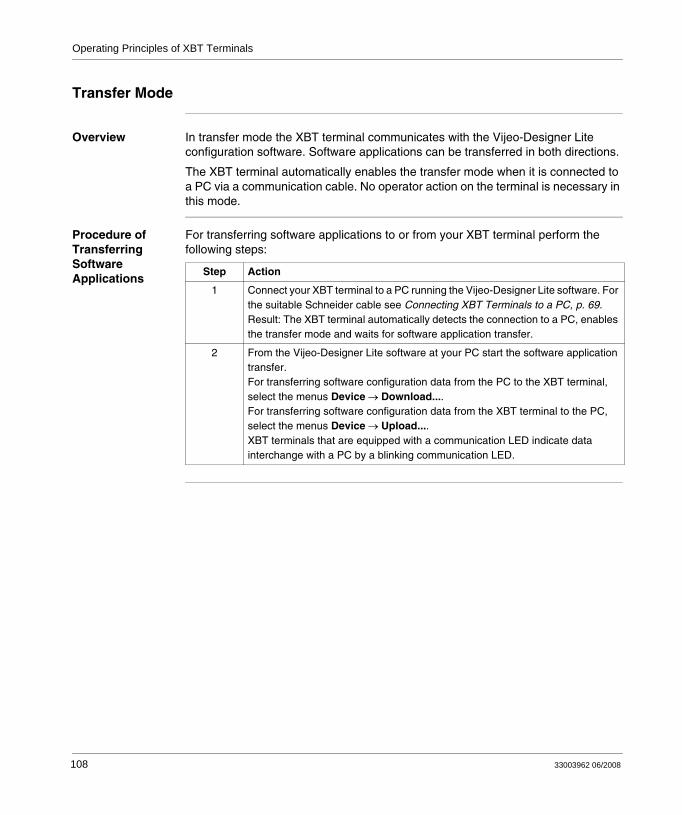
Operating Principles of XBT Terminals
Transfer Mode
Overview In transfer mode the XBT terminal communicates with the Vijeo-Designer Lite configuration software. Software applications can be transferred in both directions.
The XBT terminal automatically enables the transfer mode when it is connected to a PC via a communication cable. No operator action on the terminal is necessary in this mode.
Procedure of Transferring Software Applications
For transferring software applications to or from your XBT terminal perform the following steps:
Step Action
1 Connect your XBT terminal to a PC running the Vijeo-Designer Lite software. For the suitable Schneider cable see Connecting XBT Terminals to a PC, p. 69.Result: The XBT terminal automatically detects the connection to a PC, enables the transfer mode and waits for software application transfer.
2 From the Vijeo-Designer Lite software at your PC start the software application transfer. For transferring software configuration data from the PC to the XBT terminal, select the menus Device → Download....For transferring software configuration data from the XBT terminal to the PC, select the menus Device → Upload....XBT terminals that are equipped with a communication LED indicate data interchange with a PC by a blinking communication LED.
108 33003962 06/2008
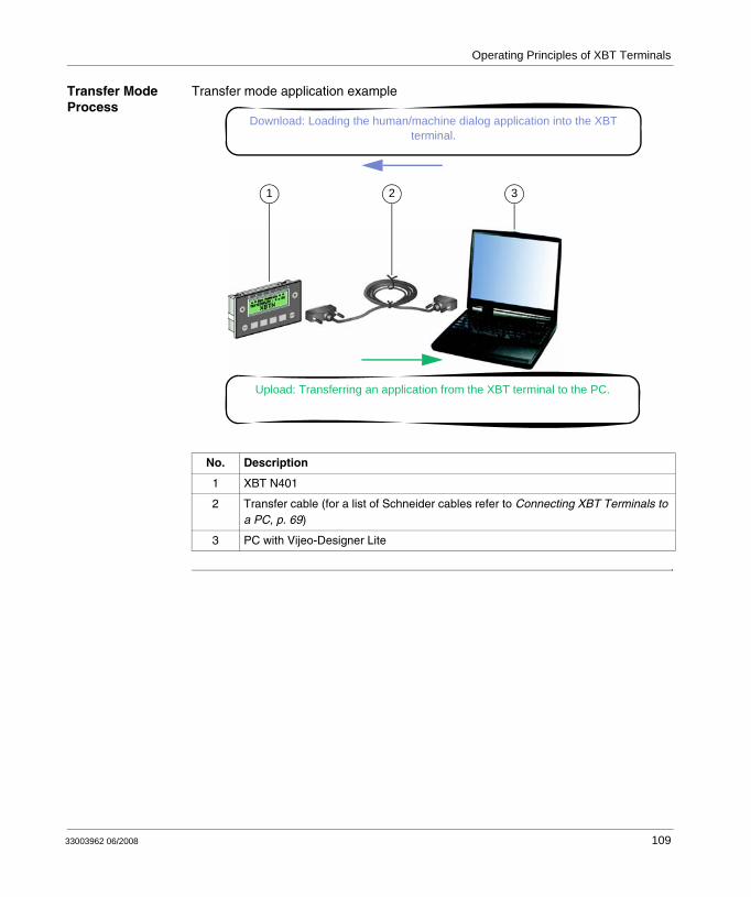
Operating Principles of XBT Terminals
Transfer Mode Process
Transfer mode application example
No. Description
1 XBT N401
2 Transfer cable (for a list of Schneider cables refer to Connecting XBT Terminals to a PC, p. 69)
3 PC with Vijeo-Designer Lite
321
Download: Loading the human/machine dialog application into the XBT terminal.
Upload: Transferring an application from the XBT terminal to the PC.
33003962 06/2008 109
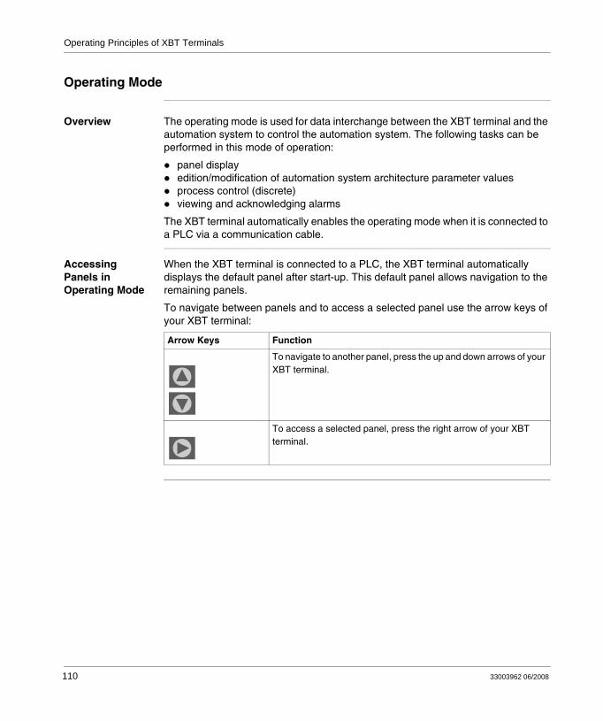
Operating Principles of XBT Terminals
Operating Mode
Overview The operating mode is used for data interchange between the XBT terminal and the automation system to control the automation system. The following tasks can be performed in this mode of operation:
panel displayedition/modification of automation system architecture parameter valuesprocess control (discrete)viewing and acknowledging alarms
The XBT terminal automatically enables the operating mode when it is connected to a PLC via a communication cable.
Accessing Panels in Operating Mode
When the XBT terminal is connected to a PLC, the XBT terminal automatically displays the default panel after start-up. This default panel allows navigation to the remaining panels.
To navigate between panels and to access a selected panel use the arrow keys of your XBT terminal:
Arrow Keys Function
To navigate to another panel, press the up and down arrows of your XBT terminal.
To access a selected panel, press the right arrow of your XBT terminal.
110 33003962 06/2008
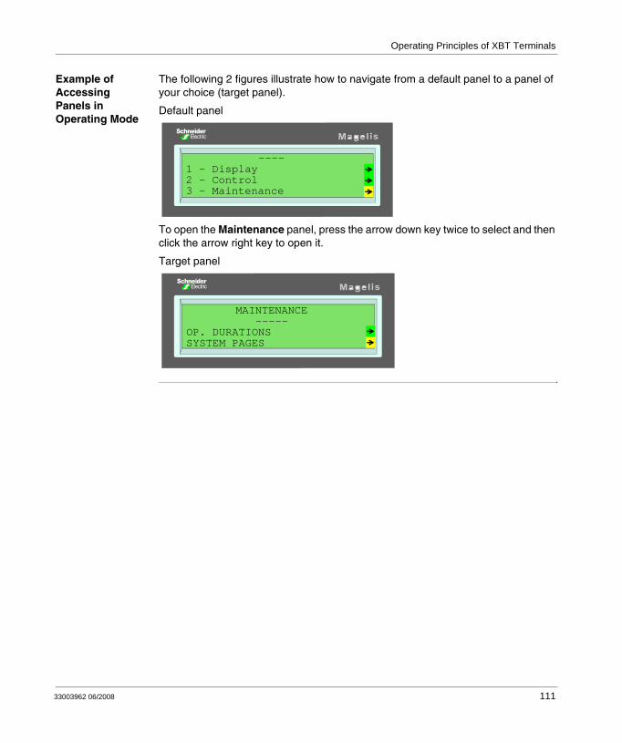
Operating Principles of XBT Terminals
Example of Accessing Panels in Operating Mode
The following 2 figures illustrate how to navigate from a default panel to a panel of your choice (target panel).
Default panel
To open the Maintenance panel, press the arrow down key twice to select and then click the arrow right key to open it.
Target panel
----1 - Display2 - Control3 - Maintenance
MAINTENANCE-----
OP. DURATIONSSYSTEM PAGES
33003962 06/2008 111
Operating Principles of XBT Terminals
10.2 Panel Structure of XBT Terminals
At a Glance
Overview XBT terminals display panels on their display unit. These panels can contain not-animated objects (e.g. background images, static texts) and not animated HMI objects (e.g. value displays, bar graphs). 3 different types of are used in XBT terminals:
application panelsalarm panelssystem panels
What's in this Section?
This section contains the following topics:
Topic Page
Principle of Application Panels 113
Displaying Application Panels 114
Principle of Alarm Panels 118
Alarm Management 119
Principle of System Panels 122
Displaying System Panels 123
Scrolling within Panels 124
112 33003962 06/2008
Operating Principles of XBT Terminals
Principle of Application Panels
Definition Application panels are panels designed to provide information about the automation system architecture being run. They also serve to clarify any operation that the operator might have to carry out in a given context.
Application panels can be interlinked to create authorized sequences during operation.
Unauthorized operators can be prevented from displaying protected panels.
33003962 06/2008 113

Operating Principles of XBT Terminals
Displaying Application Panels
Default Panel on Power-Up
When designing the application in Vijeo-Designer Lite, the designer can select a default panel.
When the terminal is powered up, this is the first panel to be displayed.
There are different ways to display application panels:
by pressing function keysby activating navigation links provided on other application panelsby pressing a button object or an active area on the touchscreen (XBT RT only)by pressing dynamic function keys Ri on products supporting this functionvia the PLCby activating links provided on system panels
Via Function Keys
It is possible to display a panel directly by pressing a function key.
Example Pressing a function key for opening a specific panel:
1 function key
F2F1 F3 F4ESC ENTER
Magelis
On
1
114 33003962 06/2008
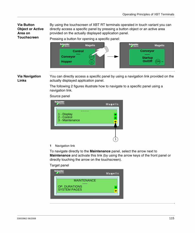
Operating Principles of XBT Terminals
Via Button Object or Active Area on Touchscreen
By using the touchscreen of XBT RT terminals operated in touch variant you can directly access a specific panel by pressing a button object or an active area provided on the actually displayed application panel.
Pressing a button for opening a specific panel:
Via Navigation Links
You can directly access a specific panel by using a navigation link provided on the actually displayed application panel.
The following 2 figures illustrate how to navigate to a specific panel using a navigation link.
Source panel
1 Navigation link
To navigate directly to the Maintenance panel, select the arrow next to Maintenance and activate this link (by using the arrow keys of the front panel or directly touching the arrow on the touchscreen).
Target panel
Magelis
Conveyor-----
Startup On/Off ON
Magelis
Control----
ConveyorHopper
----1 - Display2 - Control3 - Maintenance
1
MAINTENANCE-----
OP. DURATIONSSYSTEM PAGES
33003962 06/2008 115
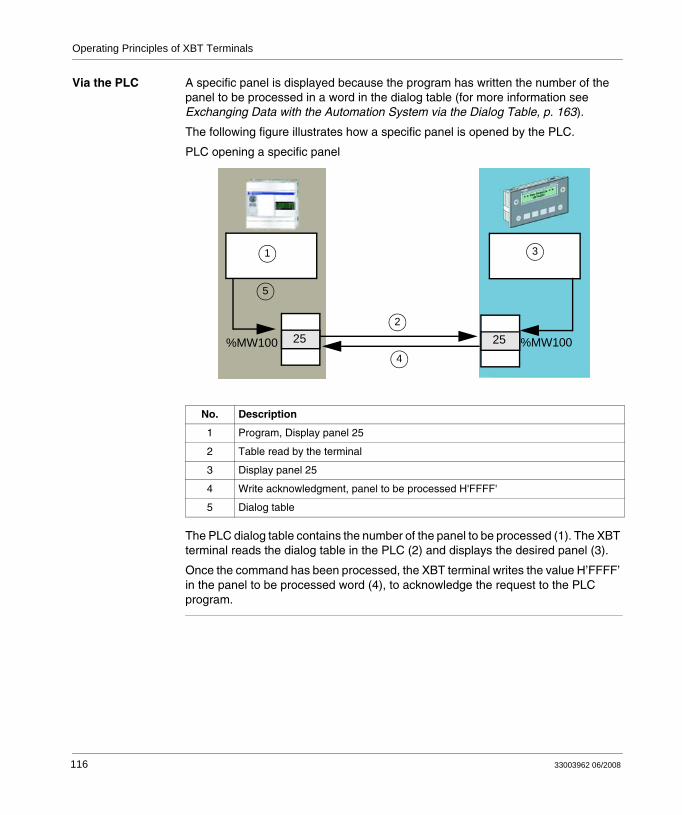
Operating Principles of XBT Terminals
Via the PLC A specific panel is displayed because the program has written the number of the panel to be processed in a word in the dialog table (for more information see Exchanging Data with the Automation System via the Dialog Table, p. 163).
The following figure illustrates how a specific panel is opened by the PLC.
PLC opening a specific panel
The PLC dialog table contains the number of the panel to be processed (1). The XBT terminal reads the dialog table in the PLC (2) and displays the desired panel (3).
Once the command has been processed, the XBT terminal writes the value H’FFFF’ in the panel to be processed word (4), to acknowledge the request to the PLC program.
No. Description
1 Program, Display panel 25
2 Table read by the terminal
3 Display panel 25
4 Write acknowledgment, panel to be processed H'FFFF'
5 Dialog table
25 25%MW100 %MW100
31
2
4
5
116 33003962 06/2008
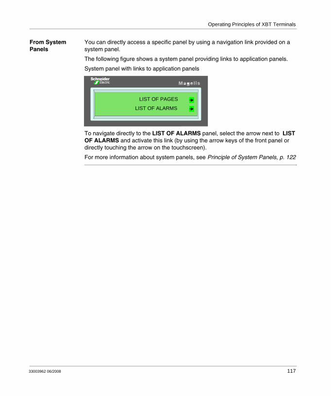
Operating Principles of XBT Terminals
From System Panels
You can directly access a specific panel by using a navigation link provided on a system panel.
The following figure shows a system panel providing links to application panels.
System panel with links to application panels
To navigate directly to the LIST OF ALARMS panel, select the arrow next to LIST OF ALARMS and activate this link (by using the arrow keys of the front panel or directly touching the arrow on the touchscreen).
For more information about system panels, see Principle of System Panels, p. 122
LIST OF PAGES
LIST OF ALARMS
33003962 06/2008 117
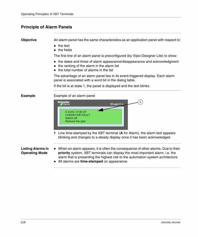
Operating Principles of XBT Terminals
Principle of Alarm Panels
Objective An alarm panel has the same characteristics as an application panel with respect to:
the textthe fields
The first line of an alarm panel is preconfigured (by Vijeo-Designer Lite) to show:
the dates and times of alarm appearance/disappearance and acknowledgmentthe ranking of the alarm in the alarm listthe total number of alarms in the list
The advantage of an alarm panel lies in its event-triggered display. Each alarm panel is associated with a word bit in the dialog table.
If the bit is at state 1, the panel is displayed and the text blinks.
Example Example of an alarm panel
1 Line time-stamped by the XBT terminal (A for Alarm), the alarm text appears blinking and changes to a steady display once it has been acknowledged.
Listing Alarms in Operating Mode
When an alarm appears, it is often the consequence of other alarms. Due to their priority system, XBT terminals can display the most important alarm, i.e. the alarm that is presenting the highest risk to the automation system architecture.All alarms are time-stamped on appearance.
A 31/01 17:35 3/7CONVEYOR FAULTSwitch off.Remove the part.
1
118 33003962 06/2008
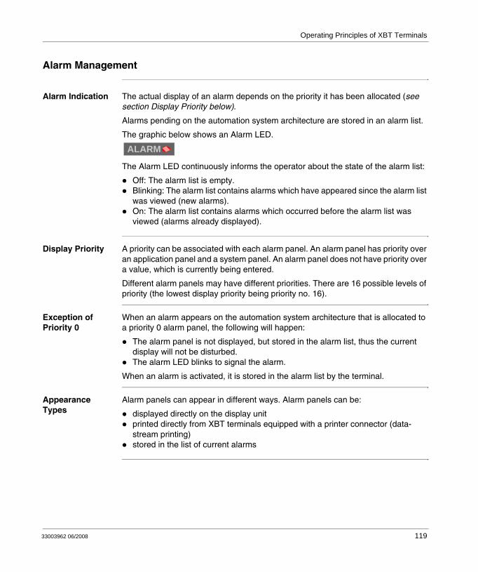
Operating Principles of XBT Terminals
Alarm Management
Alarm Indication The actual display of an alarm depends on the priority it has been allocated (see section Display Priority below).
Alarms pending on the automation system architecture are stored in an alarm list.
The graphic below shows an Alarm LED.
The Alarm LED continuously informs the operator about the state of the alarm list:
Off: The alarm list is empty.Blinking: The alarm list contains alarms which have appeared since the alarm list was viewed (new alarms).On: The alarm list contains alarms which occurred before the alarm list was viewed (alarms already displayed).
Display Priority A priority can be associated with each alarm panel. An alarm panel has priority over an application panel and a system panel. An alarm panel does not have priority over a value, which is currently being entered.
Different alarm panels may have different priorities. There are 16 possible levels of priority (the lowest display priority being priority no. 16).
Exception of Priority 0
When an alarm appears on the automation system architecture that is allocated to a priority 0 alarm panel, the following will happen:
The alarm panel is not displayed, but stored in the alarm list, thus the current display will not be disturbed.The alarm LED blinks to signal the alarm.
When an alarm is activated, it is stored in the alarm list by the terminal.
Appearance Types
Alarm panels can appear in different ways. Alarm panels can be:
displayed directly on the display unitprinted directly from XBT terminals equipped with a printer connector (data-stream printing)stored in the list of current alarms
ALARM
33003962 06/2008 119
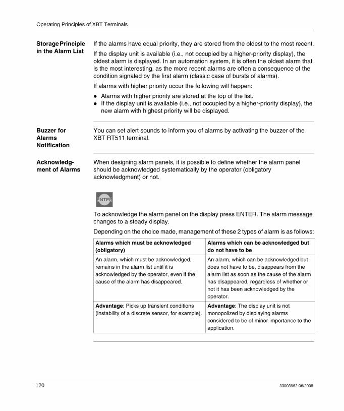
Operating Principles of XBT Terminals
Storage Principle in the Alarm List
If the alarms have equal priority, they are stored from the oldest to the most recent.
If the display unit is available (i.e., not occupied by a higher-priority display), the oldest alarm is displayed. In an automation system, it is often the oldest alarm that is the most interesting, as the more recent alarms are often a consequence of the condition signaled by the first alarm (classic case of bursts of alarms).
If alarms with higher priority occur the following will happen:
Alarms with higher priority are stored at the top of the list.If the display unit is available (i.e., not occupied by a higher-priority display), the new alarm with highest priority will be displayed.
Buzzer for Alarms Notification
You can set alert sounds to inform you of alarms by activating the buzzer of the XBT RT511 terminal.
Acknowledg-ment of Alarms
When designing alarm panels, it is possible to define whether the alarm panel should be acknowledged systematically by the operator (obligatory acknowledgment) or not.
To acknowledge the alarm panel on the display press ENTER. The alarm message changes to a steady display.
Depending on the choice made, management of these 2 types of alarm is as follows:
Alarms which must be acknowledged (obligatory)
Alarms which can be acknowledged but do not have to be
An alarm, which must be acknowledged, remains in the alarm list until it is acknowledged by the operator, even if the cause of the alarm has disappeared.
An alarm, which can be acknowledged but does not have to be, disappears from the alarm list as soon as the cause of the alarm has disappeared, regardless of whether or not it has been acknowledged by the operator.
Advantage: Picks up transient conditions (instability of a discrete sensor, for example).
Advantage: The display unit is not monopolized by displaying alarms considered to be of minor importance to the application.
ENTER
120 33003962 06/2008
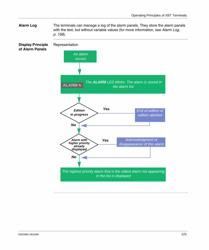
Operating Principles of XBT Terminals
Alarm Log The terminals can manage a log of the alarm panels. They store the alarm panels with the text, but without variable values (for more information, see Alarm Log, p. 156).
Display Principle of Alarm Panels
Representation
Acknowledgment or disappearance of this alarm
An alarm occurs
The ALARM LED blinks. The alarm is stored in the alarm list.
Editionin progress
End of edition or edition aborted
Alarm with higher priority
already displayed
The highest priority alarm that is the oldest alarm not appearing in the list is displayed
Yes
Yes
No
No
ALARM
33003962 06/2008 121
Operating Principles of XBT Terminals
Principle of System Panels
Definition System panels are predefined panels which are used to perform operations relating to the XBT terminal "system".
In operating mode, these panels can be accessed in the same way as application panels.
System panels are panels processed as if they were application type panels. Hence they are stored with the application panels in the developed application file.
There are 3 types of system panels:
standard system panels, which can be called by accessing an application panel (numbers 1 to 100)system panels, which cannot be called by accessing an application panel (numbers 101 to 200)popup/message system panels, which cannot be called (numbers 201 to 300)
The advantage of being able to view these panels with Vijeo-Designer Lite is that system messages can be translated.
122 33003962 06/2008

Operating Principles of XBT Terminals
Displaying System Panels
Overview System panels are accessed by means of function keys or navigation links.
When designing the application in Vijeo-Designer Lite, the designer can choose the system panels that should be associated with these keys, or these links.
List of System Panels
The following system panels are available to HMI operators:
Number Name Description
2 panel list displays a list of all application panels you can access, depending on your security access levelThe panels protected by password are listed only. The current security access level is in conformance with the security access level of the panel.
3 alarm list displays a list of all the active alarms triggered by the automation system
4 alarm history displays a list of the last events of the alarm history (coming alarms, going alarms, communication interruptions)
7 password On this panel you can enter the password to change the security access level (A, B, C, or blank password).
10 default system panel
When a terminal cannot boot and displays a certain panel (for example, the first panel is protected by password), then the terminal displays the default system panel automatically.
22 language On this panel you can choose the language of the terminal.
30 printer displays the communication parameters for the second serial line (only significant for terminals supporting a second serial line)
100 protocol displays the parameters for the communication with the equipment connected on the automation network
110 advanced displays internal alarm countersThese internal alarm counters can be of interest during calls to the technical support.
33003962 06/2008 123
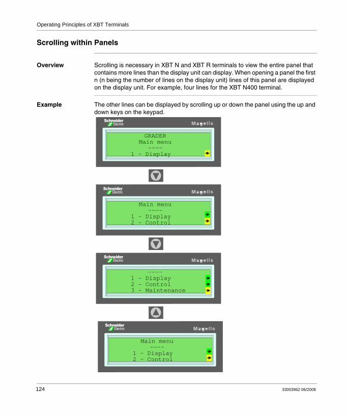
Operating Principles of XBT Terminals
Scrolling within Panels
Overview Scrolling is necessary in XBT N and XBT R terminals to view the entire panel that contains more lines than the display unit can display. When opening a panel the first n (n being the number of lines on the display unit) lines of this panel are displayed on the display unit. For example, four lines for the XBT N400 terminal.
Example The other lines can be displayed by scrolling up or down the panel using the up and down keys on the keypad.
---- 1 - Display 2 - Control 3 - Maintenance
GRADERMain menu
---- 1 - Display
Main menu----
1 - Display 2 - Control
Main menu----
1 - Display 2 - Control
124 33003962 06/2008
Operating Principles of XBT Terminals
10.3 General Configuration Settings
At a Glance
Overview This section describes general settings concerning the HMI language, the date and time format as well as access to product reference and line parameters.
What's in this Section?
This section contains the following topics:
Topic Page
Accessing Configuration Parameters via the System Panel SYSTEM 126
Selecting the HMI Language 127
Selecting the Date and Time Format 128
Accessing the Product Reference 129
Accessing the Line Parameters 130
33003962 06/2008 125
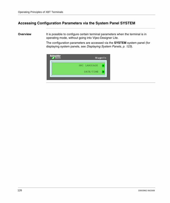
Operating Principles of XBT Terminals
Accessing Configuration Parameters via the System Panel SYSTEM
Overview It is possible to configure certain terminal parameters when the terminal is in operating mode, without going into Vijeo-Designer Lite.
The configuration parameters are accessed via the SYSTEM system panel (for displaying system panels, see Displaying System Panels, p. 123).
HMI LANGUAGE
DATE/TIME
126 33003962 06/2008
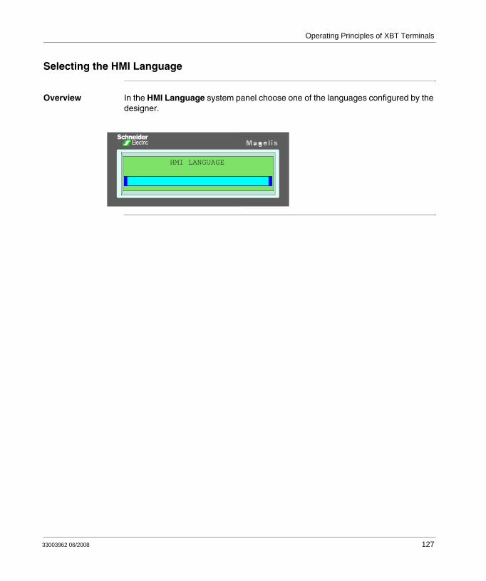
Operating Principles of XBT Terminals
Selecting the HMI Language
Overview In the HMI Language system panel choose one of the languages configured by the designer.
HMI LANGUAGE
33003962 06/2008 127
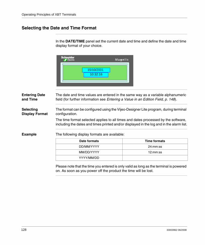
Operating Principles of XBT Terminals
Selecting the Date and Time Format
In the DATE/TIME panel set the current date and time and define the date and time display format of your choice.
Entering Date and Time
The date and time values are entered in the same way as a variable alphanumeric field (for further information see Entering a Value in an Edition Field, p. 148).
Selecting Display Format
The format can be configured using the Vijeo-Designer Lite program, during terminal configuration.
The time format selected applies to all times and dates processed by the software, including the dates and times printed and/or displayed in the log and in the alarm list.
Example The following display formats are available:
Please note that the time you entered is only valid as long as the terminal is powered on. As soon as you power off the product the time will be lost.
10:32:1615/10/2001
Date formats Time formats
DD/MM/YYYY 24:mm:ss
MM/DD/YYYY 12:mm:ss
YYYY/MM/DD
128 33003962 06/2008
Operating Principles of XBT Terminals
Accessing the Product Reference
Overview The references of the XBT terminals can be accessed from the system panels.
The references of the XBT terminal can be obtained if the designer has provided access to these panels (link to the system panels).
The following information is displayed:
product referencename of the application developed in Vijeo-Designer Litedate and time when the application file was saved in Vijeo-Designer Litecommunication protocol nameversion of Vijeo-Designer Lite used to create the applicationXBT terminal BIOS reference and versionXBT terminal application software reference and version
Note: The most important information is placed on the first few lines so that it is displayed consecutively, avoiding the need to scroll through the panel.
33003962 06/2008 129
Operating Principles of XBT Terminals
Accessing the Line Parameters
Overview System panels contain detected error counters whose content is protocol-dependent. For further information refer to the XBT protocol manual describing the protocol you are using.
130 33003962 06/2008
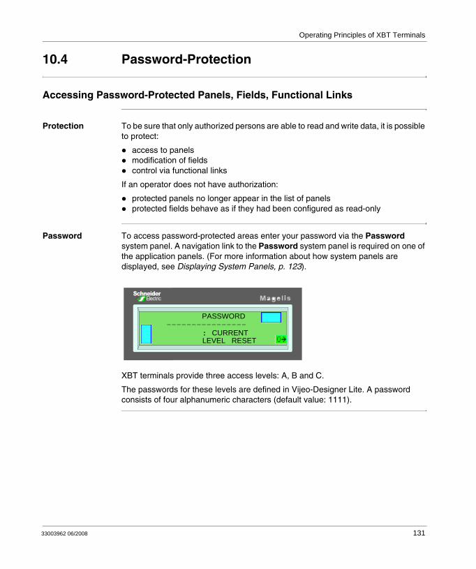
Operating Principles of XBT Terminals
10.4 Password-Protection
Accessing Password-Protected Panels, Fields, Functional Links
Protection To be sure that only authorized persons are able to read and write data, it is possible to protect:
access to panelsmodification of fieldscontrol via functional links
If an operator does not have authorization:
protected panels no longer appear in the list of panelsprotected fields behave as if they had been configured as read-only
Password To access password-protected areas enter your password via the Password system panel. A navigation link to the Password system panel is required on one of the application panels. (For more information about how system panels are displayed, see Displaying System Panels, p. 123).
XBT terminals provide three access levels: A, B and C.
The passwords for these levels are defined in Vijeo-Designer Lite. A password consists of four alphanumeric characters (default value: 1111).
PASSWORD----------------
: CURRENT LEVEL RESET
33003962 06/2008 131

Operating Principles of XBT Terminals
132 33003962 06/2008
33003962 06/2008
11
Communication Between XBT Terminals and the Automation SystemAt a Glance
Overview This chapter provides information about the communication between XBT terminals and the automation system, listing the types of commands and how they are activated as well as the processes of entering / modifying values or handling alarms.
What's in this Chapter?
This chapter contains the following sections:
Section Topic Page
11.1 Types of Commands 135
11.2 Activating Commands 138
11.3 Entering / Modifying Values Alphanumeric Fields in Edition Mode 145
11.4 Handling Alarms 153
11.5 Printing Alarms 157
133

Communication with the Automation System
134 33003962 06/2008
Communication with the Automation System
11.1 Types of Commands
At a Glance
Overview This section describes the 2 types of commands that can be sent via function keys (or functional links) or button object on touchscreen of the XBT terminal to the automation system:
impulse commandstoggle commands
What's in this Section?
This section contains the following topics:
Topic Page
Impulse Commands 136
Toggle Commands 137
33003962 06/2008 135
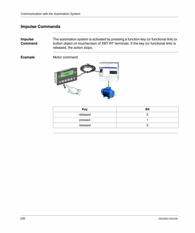
Communication with the Automation System
Impulse Commands
Impulse Command
The automation system is activated by pressing a function key (or functional link) or button object on touchscreen of XBT RT terminals. If the key (or functional link) is released, the action stops.
Example Motor command
Key Bit
released 0
pressed 1
released 0
136 33003962 06/2008
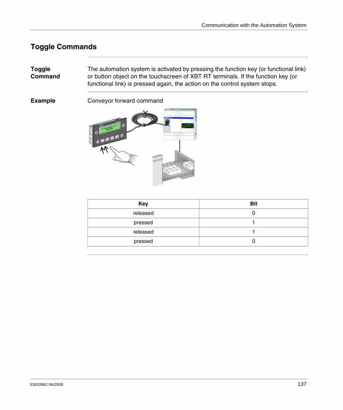
Communication with the Automation System
Toggle Commands
Toggle Command
The automation system is activated by pressing the function key (or functional link) or button object on the touchscreen of XBT RT terminals. If the function key (or functional link) is pressed again, the action on the control system stops.
Example Conveyor forward command
Key Bit
released 0
pressed 1
released 1
pressed 0
33003962 06/2008 137
Communication with the Automation System
11.2 Activating Commands
At a Glance
Overview This section describes the different ways commands can be activated at XBT terminals.
What's in this Section?
This section contains the following topics:
Topic Page
Activating Commands via Functional Links, Button Objects or Dynamic Function Keys on the Display Unit
139
Activating Commands via Function Keys on the Display Unit 144
138 33003962 06/2008
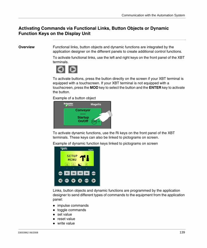
Communication with the Automation System
Activating Commands via Functional Links, Button Objects or Dynamic Function Keys on the Display Unit
Overview Functional links, button objects and dynamic functions are integrated by the application designer on the different panels to create additional control functions.
To activate functional links, use the left and right keys on the front panel of the XBT terminals.
To activate buttons, press the button directly on the screen if your XBT terminal is equipped with a touchscreen. If your XBT terminal is not equipped with a touchscreen, press the MOD key to select the button and the ENTER key to activate the button.
Example of a button object
To activate dynamic functions, use the Ri keys on the front panel of the XBT terminals. These keys can also be linked to pictograms on screen.
Example of dynamic function keys linked to pictograms on screen
Links, button objects and dynamic functions are programmed by the application designer to send different types of commands to the equipment from the application panel:
impulse commandstoggle commandsset valuereset valuewrite value
Magelis
Conveyor-----
Startup On/Off ON
33003962 06/2008 139
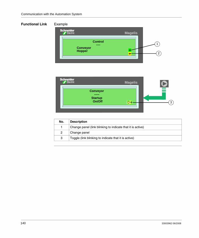
Communication with the Automation System
Functional Link Example
No. Description
1 Change panel (link blinking to indicate that it is active)
2 Change panel
3 Toggle (link blinking to indicate that it is active)
Control----
ConveyorHopper
Conveyor-----
Startup On/Off
1
2
3
Magelis
Magelis
140 33003962 06/2008
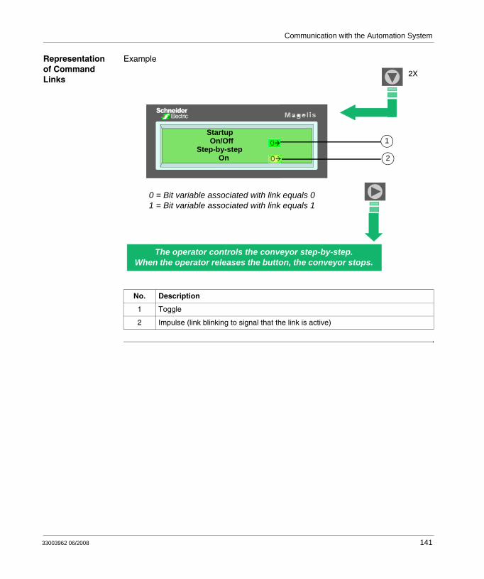
Communication with the Automation System
Representation of Command Links
Example
No. Description
1 Toggle
2 Impulse (link blinking to signal that the link is active)
2X
The operator controls the conveyor step-by-step.When the operator releases the button, the conveyor stops.
0 = Bit variable associated with link equals 01 = Bit variable associated with link equals 1
Startup On/Off
Step-by-step On
1
2
33003962 06/2008 141
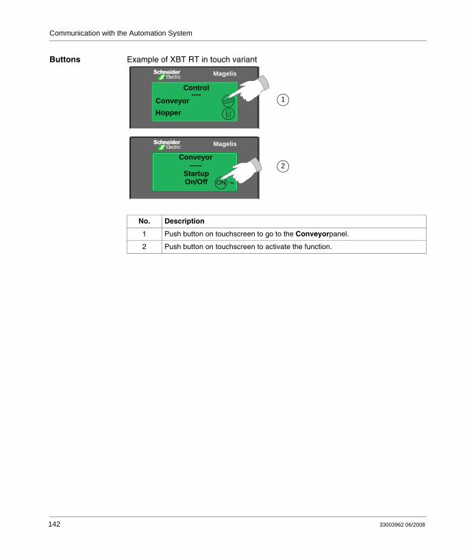
Communication with the Automation System
Buttons Example of XBT RT in touch variant
No. Description
1 Push button on touchscreen to go to the Conveyorpanel.
2 Push button on touchscreen to activate the function.
1
2
Magelis
Conveyor-----
Startup On/Off ON
Magelis
Control----
ConveyorHopper
142 33003962 06/2008
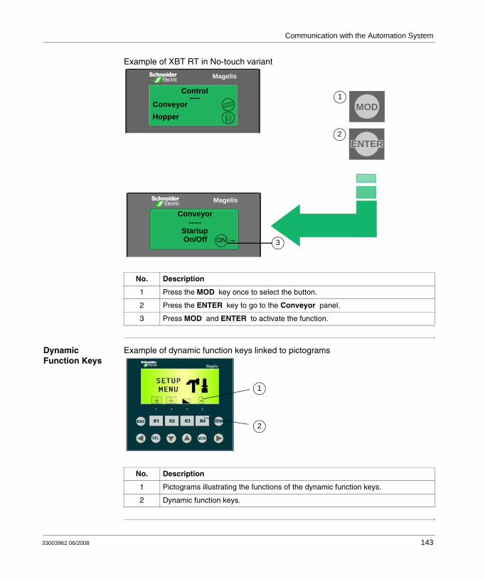
Communication with the Automation System
Example of XBT RT in No-touch variant
Dynamic Function Keys
Example of dynamic function keys linked to pictograms
No. Description
1 Press the MOD key once to select the button.
2 Press the ENTER key to go to the Conveyor panel.
3 Press MOD and ENTER to activate the function.
Magelis
Conveyor-----
Startup On/Off
ENTER
MOD1
2
3ON
Magelis
Control----
ConveyorHopper
No. Description
1 Pictograms illustrating the functions of the dynamic function keys.
2 Dynamic function keys.
1
2
33003962 06/2008 143
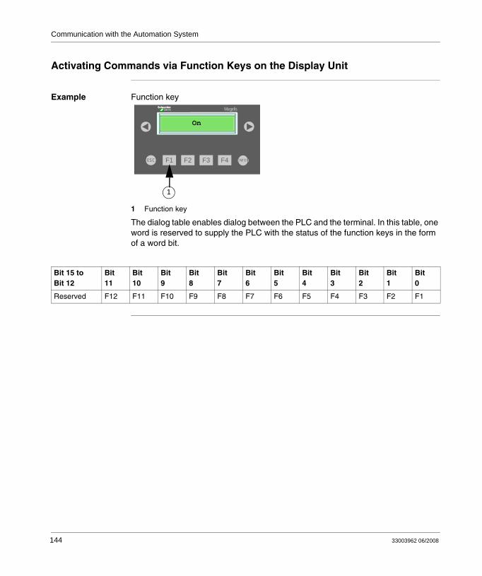
Communication with the Automation System
Activating Commands via Function Keys on the Display Unit
Example Function key
1 Function key
The dialog table enables dialog between the PLC and the terminal. In this table, one word is reserved to supply the PLC with the status of the function keys in the form of a word bit.
F2F1 F3 F4ESC ENTER
Magelis
On
1
Bit 15 toBit 12
Bit11
Bit10
Bit9
Bit8
Bit7
Bit6
Bit5
Bit4
Bit3
Bit2
Bit1
Bit0
Reserved F12 F11 F10 F9 F8 F7 F6 F5 F4 F3 F2 F1
144 33003962 06/2008
Communication with the Automation System
11.3 Entering / Modifying Values Alphanumeric Fields in Edition Mode
At a Glance
Overview This section describes how to select and modify alphanumeric fields, i.e. fields that allow to enter characters (A-Z) and numbers (0-9).
What's in this Section?
This section contains the following topics:
Topic Page
Accessing an Alphanumeric Edition Field 146
Entering a Value in an Edition Field 148
Confirming / Cancelling an Edition 150
Exit Edition on Time Out 151
Edition Report 152
33003962 06/2008 145
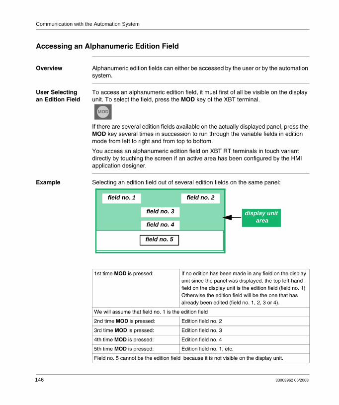
Communication with the Automation System
Accessing an Alphanumeric Edition Field
Overview Alphanumeric edition fields can either be accessed by the user or by the automation system.
User Selecting an Edition Field
To access an alphanumeric edition field, it must first of all be visible on the display unit. To select the field, press the MOD key of the XBT terminal.
If there are several edition fields available on the actually displayed panel, press the MOD key several times in succession to run through the variable fields in edition mode from left to right and from top to bottom.
You access an alphanumeric edition field on XBT RT terminals in touch variant directly by touching the screen if an active area has been configured by the HMI application designer.
Example Selecting an edition field out of several edition fields on the same panel:
MOD
1st time MOD is pressed: If no edition has been made in any field on the display unit since the panel was displayed, the top left-hand field on the display unit is the edition field (field no. 1)Otherwise the edition field will be the one that has already been edited (field no. 1, 2, 3 or 4).
We will assume that field no. 1 is the edition field
2nd time MOD is pressed: Edition field no. 2
3rd time MOD is pressed: Edition field no. 3
4th time MOD is pressed: Edition field no. 4
5th time MOD is pressed: Edition field no. 1, etc.
Field no. 5 cannot be the edition field because it is not visible on the display unit.
field no. 1 field no. 2
field no. 3
field no. 5
field no. 4
field no. 5
display unit area
146 33003962 06/2008
Communication with the Automation System
Automation System Accessing an Edition Field
The connected device sets a variable field into edition mode by writing its number in a word in the dialog table. To display the number of variable fields in Vijeo-Designer Lite, use the Layout → Display Fields Indices menu.
In return, the XBT terminal writes the number of the field being completed in a word in the dialog table (see Exchanging Data with the Automation System via the Dialog Table, p. 163).
Specific feature of this type of selection:
You cannot select another variable field at the XBT terminal until the one requested by the connected device has been completed because the MOD key is inactive during this time.
33003962 06/2008 147
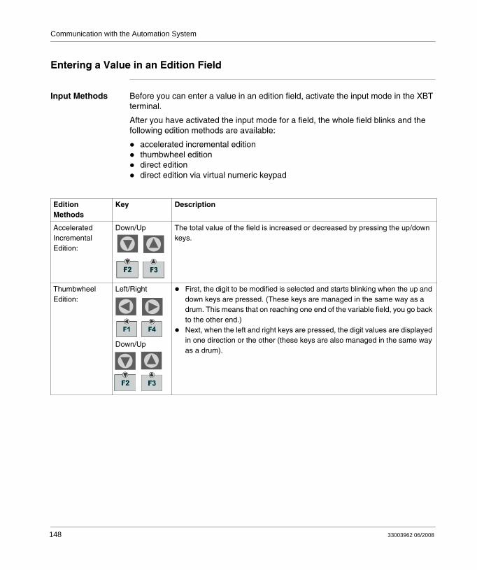
Communication with the Automation System
Entering a Value in an Edition Field
Input Methods Before you can enter a value in an edition field, activate the input mode in the XBT terminal.
After you have activated the input mode for a field, the whole field blinks and the following edition methods are available:
accelerated incremental editionthumbwheel editiondirect editiondirect edition via virtual numeric keypad
Edition Methods
Key Description
Accelerated Incremental Edition:
Down/Up The total value of the field is increased or decreased by pressing the up/down keys.
Thumbwheel Edition:
Left/Right
Down/Up
First, the digit to be modified is selected and starts blinking when the up and down keys are pressed. (These keys are managed in the same way as a drum. This means that on reaching one end of the variable field, you go back to the other end.)Next, when the left and right keys are pressed, the digit values are displayed in one direction or the other (these keys are also managed in the same way as a drum).
148 33003962 06/2008

Communication with the Automation System
Direct Edition (XBT R4•• only):
Key F1 to F12 Keys F1 to F12 are dual labelled Fx/Nx (function/numeric) keys. They can be used to modify values directly. The correspondence between keys and numeric values is as follows:
Key Value
F1 1
F2 2
F3 3
F4 4
F5 5
F6 6
F7 7
F8 8
F9 9
F10 0
F11 +/-
F12 .
Direct Input via Virtual numeric Keypad (XBT RT in touch variant only):
Virtual numeric keypad on touchscreen of XBT RT:
Activate the individual buttons on the touchscreen with your finger to enter the respective character.
Edition Methods
Key Description
F1
33003962 06/2008 149
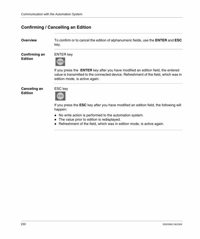
Communication with the Automation System
Confirming / Cancelling an Edition
Overview To confirm or to cancel the edition of alphanumeric fields, use the ENTER and ESC key.
Confirming an Edition
ENTER key
If you press the ENTER key after you have modified an edition field, the entered value is transmitted to the connected device. Refreshment of the field, which was in edition mode, is active again.
Canceling an Edition
ESC key
If you press the ESC key after you have modified an edition field, the following will happen:
No write action is performed to the automation system.The value prior to edition is redisplayed.Refreshment of the field, which was in edition mode, is active again.
ENTER
ESC
150 33003962 06/2008
Communication with the Automation System
Exit Edition on Time Out
Overview If you have enabled edition mode but you do not press any key for more than 1 minute, edition mode will be disabled automatically and the following will happen:
No write action is performed to the automation system.Refreshment of the field, which was in edition mode, is active again.
33003962 06/2008 151
Communication with the Automation System
Edition Report
Overview After the edition mode has been disabled, the connected equipment is informed of how the edition ended:
confirmationcancellationtime out
by updating the Report word in the dialog table.
152 33003962 06/2008
Communication with the Automation System
11.4 Handling Alarms
At a Glance
Overview This section describes how to view, ignore and print alarms.
Please note that these functions are not available for XBT N200 terminals.
What's in this Section?
This section contains the following topics:
Topic Page
Viewing or Ignoring Alarms 154
Alarm Log 156
33003962 06/2008 153
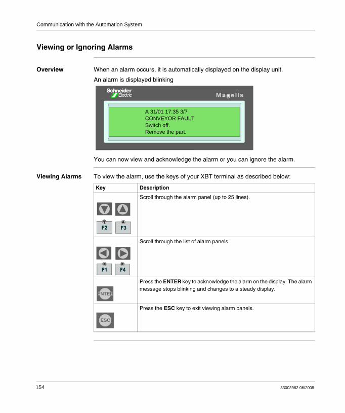
Communication with the Automation System
Viewing or Ignoring Alarms
Overview When an alarm occurs, it is automatically displayed on the display unit.
An alarm is displayed blinking
You can now view and acknowledge the alarm or you can ignore the alarm.
Viewing Alarms To view the alarm, use the keys of your XBT terminal as described below:
A 31/01 17:35 3/7CONVEYOR FAULTSwitch off.Remove the part.
Key Description
Scroll through the alarm panel (up to 25 lines).
Scroll through the list of alarm panels.
Press the ENTER key to acknowledge the alarm on the display. The alarm message stops blinking and changes to a steady display.
Press the ESC key to exit viewing alarm panels.
ENTER
ESC
154 33003962 06/2008
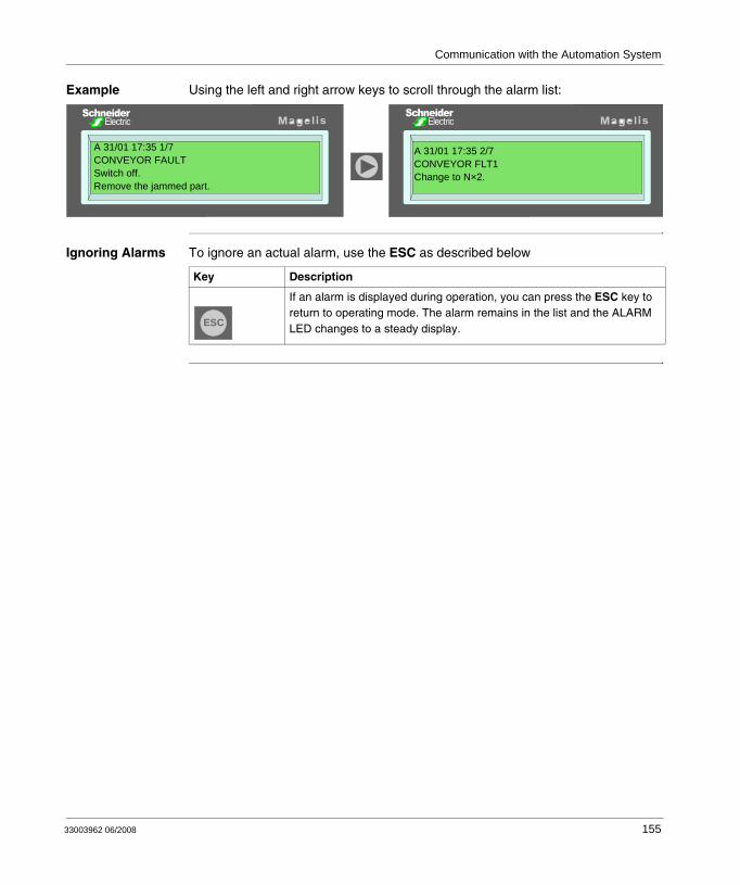
Communication with the Automation System
Example Using the left and right arrow keys to scroll through the alarm list:
Ignoring Alarms To ignore an actual alarm, use the ESC as described below
A 31/01 17:35 1/7CONVEYOR FAULTSwitch off.Remove the jammed part.
A 31/01 17:35 2/7CONVEYOR FLT1Change to N×2.
Key Description
If an alarm is displayed during operation, you can press the ESC key to return to operating mode. The alarm remains in the list and the ALARM LED changes to a steady display.ESC
33003962 06/2008 155
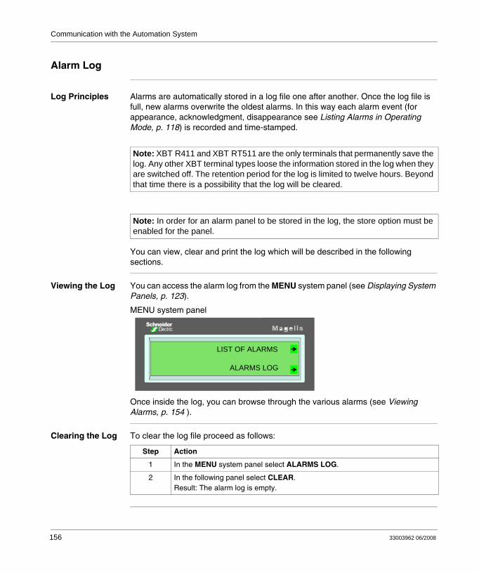
Communication with the Automation System
Alarm Log
Log Principles Alarms are automatically stored in a log file one after another. Once the log file is full, new alarms overwrite the oldest alarms. In this way each alarm event (for appearance, acknowledgment, disappearance see Listing Alarms in Operating Mode, p. 118) is recorded and time-stamped.
You can view, clear and print the log which will be described in the following sections.
Viewing the Log You can access the alarm log from the MENU system panel (see Displaying System Panels, p. 123).
MENU system panel
Once inside the log, you can browse through the various alarms (see Viewing Alarms, p. 154 ).
Clearing the Log To clear the log file proceed as follows:
Note: XBT R411 and XBT RT511 are the only terminals that permanently save the log. Any other XBT terminal types loose the information stored in the log when they are switched off. The retention period for the log is limited to twelve hours. Beyond that time there is a possibility that the log will be cleared.
Note: In order for an alarm panel to be stored in the log, the store option must be enabled for the panel.
LIST OF ALARMS
ALARMS LOG
Step Action
1 In the MENU system panel select ALARMS LOG.
2 In the following panel select CLEAR.Result: The alarm log is empty.
156 33003962 06/2008
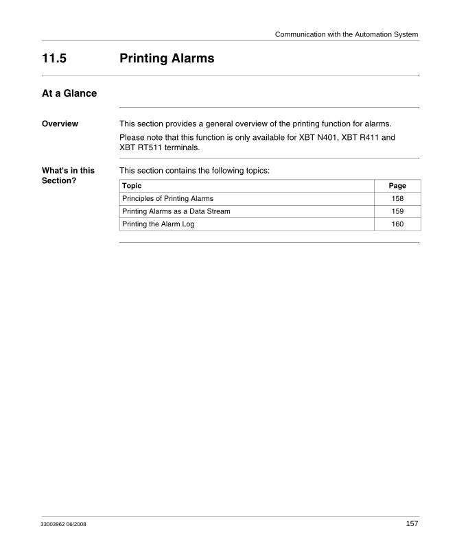
Communication with the Automation System
11.5 Printing Alarms
At a Glance
Overview This section provides a general overview of the printing function for alarms.
Please note that this function is only available for XBT N401, XBT R411 and XBT RT511 terminals.
What's in this Section?
This section contains the following topics:
Topic Page
Principles of Printing Alarms 158
Printing Alarms as a Data Stream 159
Printing the Alarm Log 160
33003962 06/2008 157
Communication with the Automation System
Principles of Printing Alarms
Overview You can print alarms in the following different ways that will be described in the following sections:
printing alarms as a data streamprinting the alarm logprinting the list of current alarms
158 33003962 06/2008
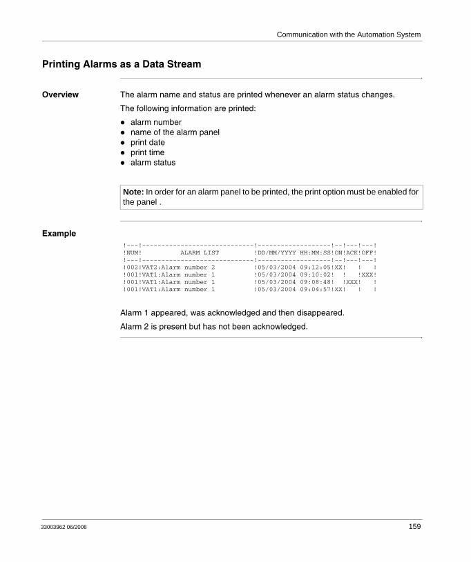
Communication with the Automation System
Printing Alarms as a Data Stream
Overview The alarm name and status are printed whenever an alarm status changes.
The following information are printed:
alarm numbername of the alarm panelprint dateprint timealarm status
Example
Alarm 1 appeared, was acknowledged and then disappeared.
Alarm 2 is present but has not been acknowledged.
Note: In order for an alarm panel to be printed, the print option must be enabled for the panel .
!---!-----------------------------!-------------------!--!---!---!!NUM! ALARM LIST !DD/MM/YYYY HH:MM:SS!ON!ACK!OFF!!---!-----------------------------!-------------------!--!---!---!!002!VAT2:Alarm number 2 !05/03/2004 09:12:05!XX! ! !!001!VAT1:Alarm number 1 !05/03/2004 09:10:02! ! !XXX!!001!VAT1:Alarm number 1 !05/03/2004 09:08:48! !XXX! !!001!VAT1:Alarm number 1 !05/03/2004 09:04:57!XX! ! !
33003962 06/2008 159

Communication with the Automation System
Printing the Alarm Log
Initiated by the Operator
The log is printed in sequential order (sorted by status), with the most recent alarm at the top.
The following information is printed for each alarm:
its numbername of the alarm paneldate and time of appearancedate and time of acknowledgmentdate and time of disappearance
Initiated by the PLC
The log is printed by means of the print command word in the dialog table.
The log is printed in sequential order (sorted by status), with the most recent alarm at the top.
The following information is printed for each alarm:
alarm numbername of the alarm paneldate and time of appearancedate and time of acknowledgmentdate and time of disappearance
Example
Alarm 1 appeared, was acknowledged and then disappeared.
Alarm 2 is present but has not been acknowledged.
!---!-----------------------------!-------------------!--!---!---!!NUM! ALARM LIST !DD/MM/YYYY HH:MM:SS!ON!ACK!OFF!!---!-----------------------------!-------------------!--!---!---!!002!VAT2:Alarm number 2 !05/03/2004 09:12:05!XX! ! !!001!VAT1:Alarm number 1 !05/03/2004 09:10:02! ! !XXX!!001!VAT1:Alarm number 1 !05/03/2004 09:08:48! !XXX! !!001!VAT1:Alarm number 1 !05/03/2004 09:04:57!XX! ! !
160 33003962 06/2008
33003962 06/2008
12
Vijeo-Designer Lite Configuration SoftwareAt a Glance
Overview This chapter provides a short reference to the Vijeo-Designer Lite configuration software for XBT terminals.
What's in this Chapter?
This chapter contains the following topics:
Topic Page
Creating XBT Terminal Applications 162
Exchanging Data with the Automation System via the Dialog Table 163
161
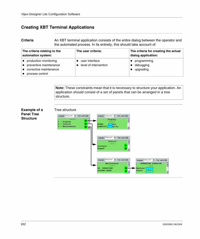
Vijeo-Designer Lite Configuration Software
Creating XBT Terminal Applications
Criteria An XBT terminal application consists of the entire dialog between the operator and the automated process. In its entirety, this should take account of:
Example of a Panel Tree Structure
Tree structure
The criteria relating to the automation system:
The user criteria: The criteria for creating the actual dialog application:
production monitoringpreventive maintenancecorrective maintenanceprocess control
user interfacelevel of intervention
programmingdebuggingupgrading
Note: These constraints mean that it is necessary to structure your application. An application should consist of a set of panels that can be arranged in a tree structure.
-----1 - Display2 - Control3 - Maintenance
Control----
ConveyorHopper
Maintenance-----
OP. DURATIONS SYSTEM PAGES
Display-----
SPEED M/minQUANTITY Amt/hr
OPERATING DURATION----
Machine hrGuard hr
ENGLISH* ENGLISH*
ENGLISH*
ENGLISH* ENGLISH*
162 33003962 06/2008
Vijeo-Designer Lite Configuration Software
Exchanging Data with the Automation System via the Dialog Table
Overview Dialog tables are integrated in the PLCs that are connected to XBT terminals.
A dialog table is a set of data exchanged between the PLC and the XBT terminal.
Dialog tables are used to inform terminals of alarm states.
For more information on the data exchange between XBT terminals and connected equipment via dialog tables refer to the Vijeo-Designer Lite online help.
33003962 06/2008 163

Vijeo-Designer Lite Configuration Software
164 33003962 06/2008
Appendices
At a Glance
Overview This part provides additional information on this manual.
What's in this Appendix?
The appendix contains the following chapters:
Chapter Chapter Name Page
A Troubleshooting and Further Information 167
B Architectures of Automation Systems 175
33003962 06/2008 165

Appendices
166 33003962 06/2008

33003962 06/2008
A
Troubleshooting and Further InformationAt a Glance
Overview This chapter provides additional information about troubleshooting, alert messages, internal variables and self-tests of the terminals.
What's in this Chapter?
This chapter contains the following topics:
Topic Page
Troubleshooting 168
System Messages 170
Internal Variables 172
Terminal Self-Tests 174
167
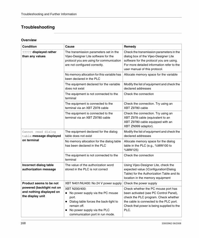
Troubleshooting and Further Information
Troubleshooting
Overview
Condition Cause Remedy
????? displayed rather than any values
The transmission parameters set in the Vijeo-Designer Lite software for the protocol you are using for communication are not configured correctly.
Check the transmission parameters in the dialog box of the Vijeo-Designer Lite software for the protocol you are using. For more detailed information refer to the user manual of this protocol.
No memory allocation for this variable has been declared in the PLC
Allocate memory space for the variable
The equipment declared for the variable does not exist
Modify the list of equipment and check the declared addresses
The equipment is not connected to the terminal
Check the connection
The equipment is connected to the terminal via an XBT Z978 cable
Check the connection. Try using an XBT Z9780 cable
The equipment is connected to the terminal via an XBT Z9780 cable
Check the connection. Try using an XBT Z978 cable (equivalent to an XBT Z9780 cable equipped with an XBT ZN999 adaptor).
Cannot read dialog table message displayed on terminal
The equipment declared for the dialog table does not exist
Modify the list of equipment and check the declared addresses
No memory allocation for the dialog table has been declared in the PLC
Allocate memory space for the dialog table in the PLC (e.g., %MW100 to %MW125)
The equipment is not connected to the terminal
Check the connection
Incorrect dialog table authorization message
The value of the authorization word stored in the PLC is not correct
Using Vijeo-Designer Lite, check the expected value (\Configuration\Dialog Table) for the Authorization Table and its location in the memory equipment
Product seems to be not powered (backlight not on and nothing displayed on the display unit
XBT N401/NU400: No 24 V power supply Check the power supply
XBT N200/400:No power supply via the PC mouse port.Dialog table forces the back-light to remain off.No power supply via the PLC communication port in run mode.
Check whether the PC mouse port has been activated (see PC Control Panel), check the PLC program. Check whether the cable is connected to the PLC port. Check that power is being supplied to the PLC.
168 33003962 06/2008
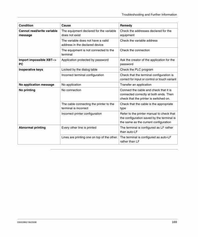
Troubleshooting and Further Information
Cannot read/write variable message
The equipment declared for the variable does not exist
Check the addresses declared for the equipment
The variable does not have a valid address in the declared device
Check the variable address
The equipment is not connected to the terminal
Check the connection
Import impossible XBT--> PC
Application protected by password Ask the creator of the application for the password
Inoperative keys Locked by the dialog table Check the PLC program
Incorrect terminal configuration Check that the terminal configuration is correct for input or control or touch variant
No application message No application Transfer an application
No printing No connection Connect the cable and check that it is connected correctly at both ends. Then check that the printer is switched on.
The cable connecting the printer to the terminal is incorrect
Check that the cable is the appropriate type
Incorrect printer configuration Refer to the printer manual to check that the configuration saved by the terminal is the same as the current configuration
Abnormal printing Every other line is printed The terminal is configured as LF rather than auto-LF
Lines are printing one on top of the other. The terminal is configured as auto-LF rather than LF
Condition Cause Remedy
33003962 06/2008 169
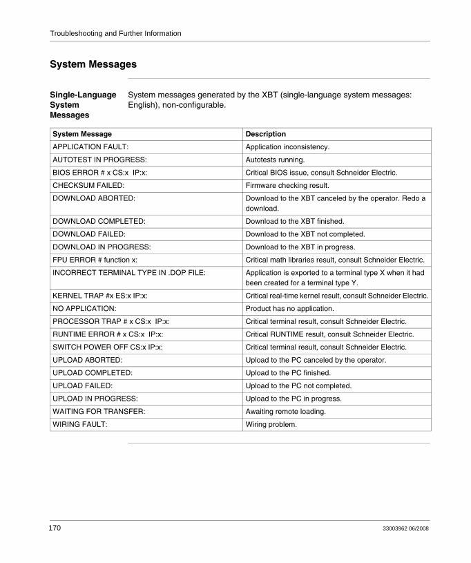
Troubleshooting and Further Information
System Messages
Single-Language System Messages
System messages generated by the XBT (single-language system messages: English), non-configurable.
System Message Description
APPLICATION FAULT: Application inconsistency.
AUTOTEST IN PROGRESS: Autotests running.
BIOS ERROR # x CS:x IP:x: Critical BIOS issue, consult Schneider Electric.
CHECKSUM FAILED: Firmware checking result.
DOWNLOAD ABORTED: Download to the XBT canceled by the operator. Redo a download.
DOWNLOAD COMPLETED: Download to the XBT finished.
DOWNLOAD FAILED: Download to the XBT not completed.
DOWNLOAD IN PROGRESS: Download to the XBT in progress.
FPU ERROR # function x: Critical math libraries result, consult Schneider Electric.
INCORRECT TERMINAL TYPE IN .DOP FILE: Application is exported to a terminal type X when it had been created for a terminal type Y.
KERNEL TRAP #x ES:x IP:x: Critical real-time kernel result, consult Schneider Electric.
NO APPLICATION: Product has no application.
PROCESSOR TRAP # x CS:x IP:x: Critical terminal result, consult Schneider Electric.
RUNTIME ERROR # x CS:x IP:x: Critical RUNTIME result, consult Schneider Electric.
SWITCH POWER OFF CS:x IP:x: Critical terminal result, consult Schneider Electric.
UPLOAD ABORTED: Upload to the PC canceled by the operator.
UPLOAD COMPLETED: Upload to the PC finished.
UPLOAD FAILED: Upload to the PC not completed.
UPLOAD IN PROGRESS: Upload to the PC in progress.
WAITING FOR TRANSFER: Awaiting remote loading.
WIRING FAULT: Wiring problem.
170 33003962 06/2008
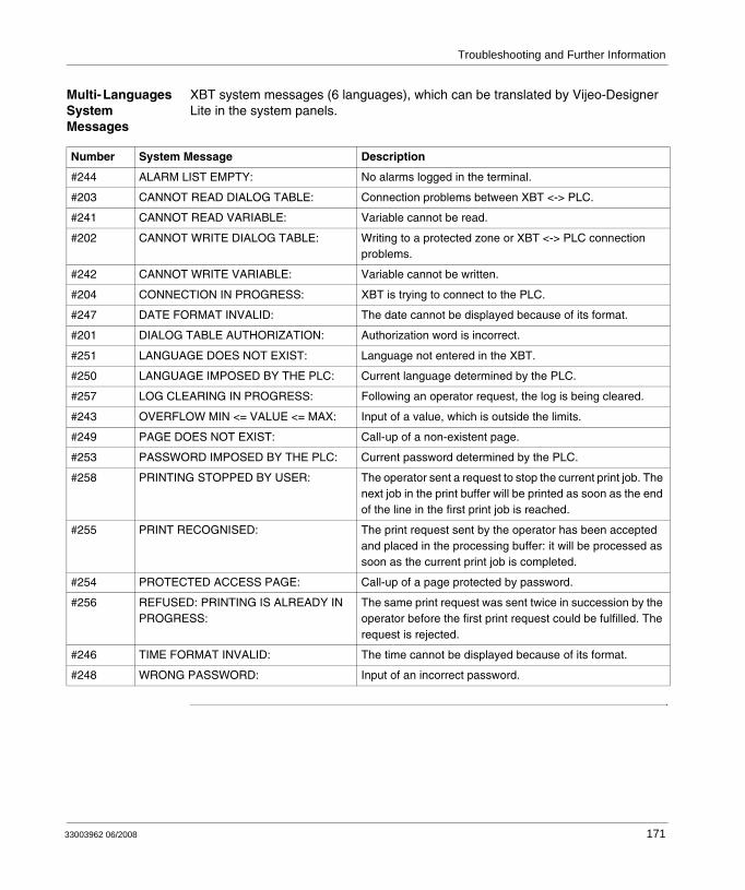
Troubleshooting and Further Information
Multi- Languages System Messages
XBT system messages (6 languages), which can be translated by Vijeo-Designer Lite in the system panels.
Number System Message Description
#244 ALARM LIST EMPTY: No alarms logged in the terminal.
#203 CANNOT READ DIALOG TABLE: Connection problems between XBT <-> PLC.
#241 CANNOT READ VARIABLE: Variable cannot be read.
#202 CANNOT WRITE DIALOG TABLE: Writing to a protected zone or XBT <-> PLC connection problems.
#242 CANNOT WRITE VARIABLE: Variable cannot be written.
#204 CONNECTION IN PROGRESS: XBT is trying to connect to the PLC.
#247 DATE FORMAT INVALID: The date cannot be displayed because of its format.
#201 DIALOG TABLE AUTHORIZATION: Authorization word is incorrect.
#251 LANGUAGE DOES NOT EXIST: Language not entered in the XBT.
#250 LANGUAGE IMPOSED BY THE PLC: Current language determined by the PLC.
#257 LOG CLEARING IN PROGRESS: Following an operator request, the log is being cleared.
#243 OVERFLOW MIN <= VALUE <= MAX: Input of a value, which is outside the limits.
#249 PAGE DOES NOT EXIST: Call-up of a non-existent page.
#253 PASSWORD IMPOSED BY THE PLC: Current password determined by the PLC.
#258 PRINTING STOPPED BY USER: The operator sent a request to stop the current print job. The next job in the print buffer will be printed as soon as the end of the line in the first print job is reached.
#255 PRINT RECOGNISED: The print request sent by the operator has been accepted and placed in the processing buffer: it will be processed as soon as the current print job is completed.
#254 PROTECTED ACCESS PAGE: Call-up of a page protected by password.
#256 REFUSED: PRINTING IS ALREADY IN PROGRESS:
The same print request was sent twice in succession by the operator before the first print request could be fulfilled. The request is rejected.
#246 TIME FORMAT INVALID: The time cannot be displayed because of its format.
#248 WRONG PASSWORD: Input of an incorrect password.
33003962 06/2008 171
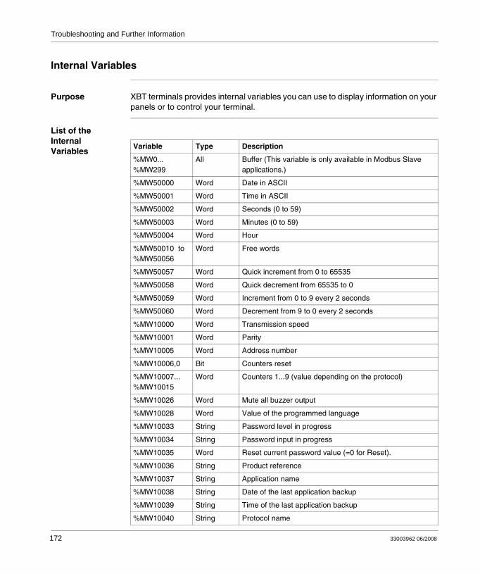
Troubleshooting and Further Information
Internal Variables
Purpose XBT terminals provides internal variables you can use to display information on your panels or to control your terminal.
List of the Internal Variables
Variable Type Description
%MW0... %MW299
All Buffer (This variable is only available in Modbus Slave applications.)
%MW50000 Word Date in ASCII
%MW50001 Word Time in ASCII
%MW50002 Word Seconds (0 to 59)
%MW50003 Word Minutes (0 to 59)
%MW50004 Word Hour
%MW50010 to %MW50056
Word Free words
%MW50057 Word Quick increment from 0 to 65535
%MW50058 Word Quick decrement from 65535 to 0
%MW50059 Word Increment from 0 to 9 every 2 seconds
%MW50060 Word Decrement from 9 to 0 every 2 seconds
%MW10000 Word Transmission speed
%MW10001 Word Parity
%MW10005 Word Address number
%MW10006,0 Bit Counters reset
%MW10007... %MW10015
Word Counters 1...9 (value depending on the protocol)
%MW10026 Word Mute all buzzer output
%MW10028 Word Value of the programmed language
%MW10033 String Password level in progress
%MW10034 String Password input in progress
%MW10035 Word Reset current password value (=0 for Reset).
%MW10036 String Product reference
%MW10037 String Application name
%MW10038 String Date of the last application backup
%MW10039 String Time of the last application backup
%MW10040 String Protocol name
172 33003962 06/2008
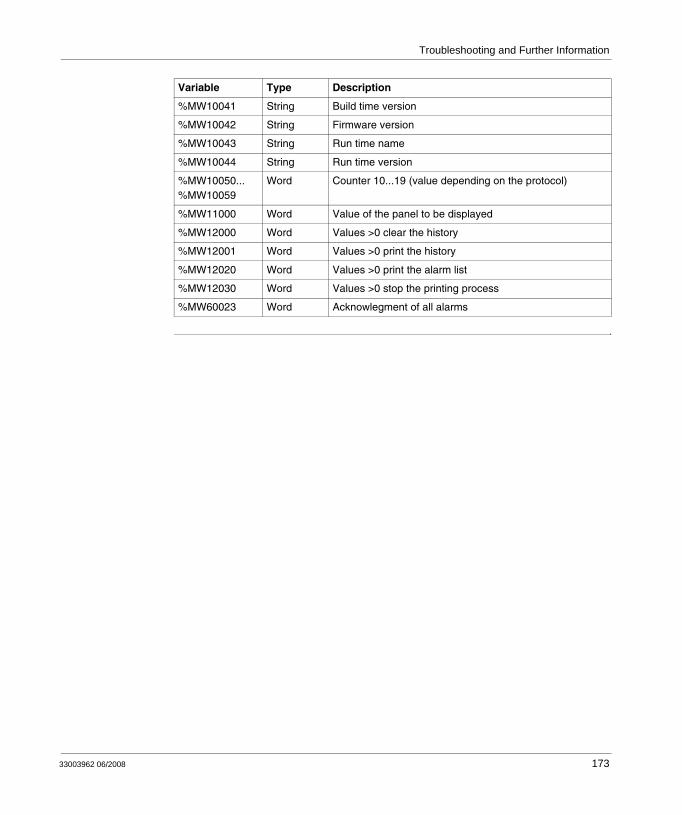
Troubleshooting and Further Information
%MW10041 String Build time version
%MW10042 String Firmware version
%MW10043 String Run time name
%MW10044 String Run time version
%MW10050... %MW10059
Word Counter 10...19 (value depending on the protocol)
%MW11000 Word Value of the panel to be displayed
%MW12000 Word Values >0 clear the history
%MW12001 Word Values >0 print the history
%MW12020 Word Values >0 print the alarm list
%MW12030 Word Values >0 stop the printing process
%MW60023 Word Acknowlegment of all alarms
Variable Type Description
33003962 06/2008 173

Troubleshooting and Further Information
Terminal Self-Tests
Overview XBT terminals perform 2 types of self-tests:
self-test during power-upcontinuous self-test during operation
Self-Test Power-Up
When the terminal is powered up, the following self-tests are performed:
Continuous Self-Test
A continuous self-test checks that the program is operating correctly (watchdog).
Element Tested Test Principle Non-passing Result Criterion Action in Event of Non-Passing
The working memory (RAM)
Writing/reading Value read different from value written
Operation impossible: STOP
The firmware Checksum calculation and checking
Calculated checksum <> stored checksum
Operation impossible: STOP
The application memory
Checksum calculation and checking
Calculated checksum <> stored checksum
Operation impossible: Transfer compulsory
Note: If a problem is detected that prevents operation of the product, the terminal turns off all its LEDs, stops working and displays a system message number (if the detected condition permits it to do so). If the same problem still persists after the terminal has been switched back on, inform the maintenance department of this system message number.
174 33003962 06/2008
33003962 06/2008
B
Architectures of Automation SystemsTypes of Architectures of Automation Systems
Communication via Protocols
Communication between the XBT terminal and connected equipment is achieved by means of a communication protocol, which is selected when creating the application in Vijeo-Designer Lite.
The protocols available for the XBT range support communication with the Schneider range of PLCs, specific equipment (speed drives) and third party PLCs.
Supported protocols are Uni-Telway, Modbus (master and slave), Siemens PPI, AB DF1, AB DH485, Mitsubishi FX, SYSMAC-WAY. Please note that not all XBT types support all protocols.
The following types of architecture are possible, which enable 1 XBT terminal to be linked to several equipment or several XBT terminals to 1 equipment:
point-to-point connectionsmultipoint connectionsmultidrop connections
For more information on the protocols, please refer to the Protocols User Manuals.
175
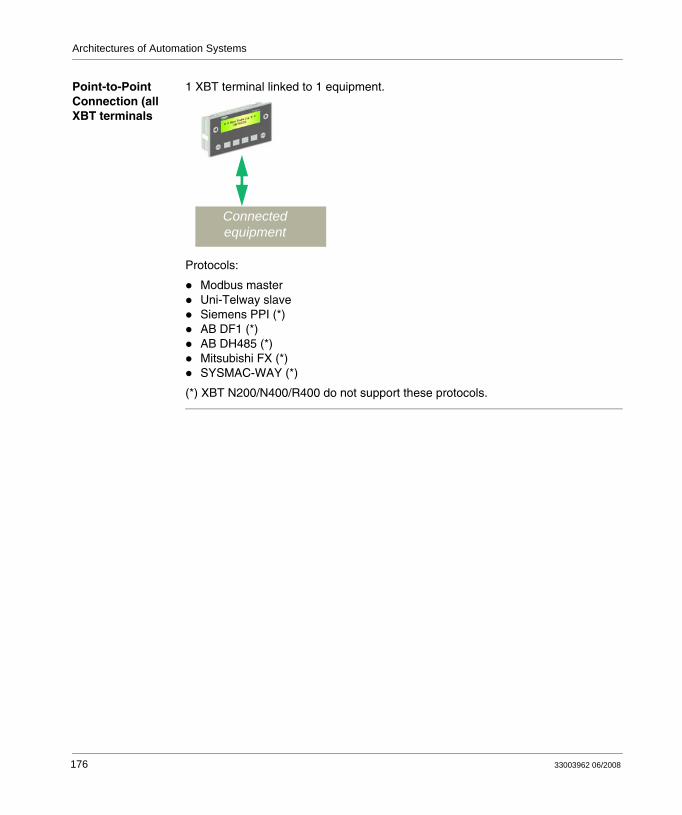
Architectures of Automation Systems
Point-to-Point Connection (all XBT terminals
1 XBT terminal linked to 1 equipment.
Protocols:
Modbus masterUni-Telway slaveSiemens PPI (*)AB DF1 (*)AB DH485 (*)Mitsubishi FX (*)SYSMAC-WAY (*)
(*) XBT N200/N400/R400 do not support these protocols.
Connected equipment
176 33003962 06/2008
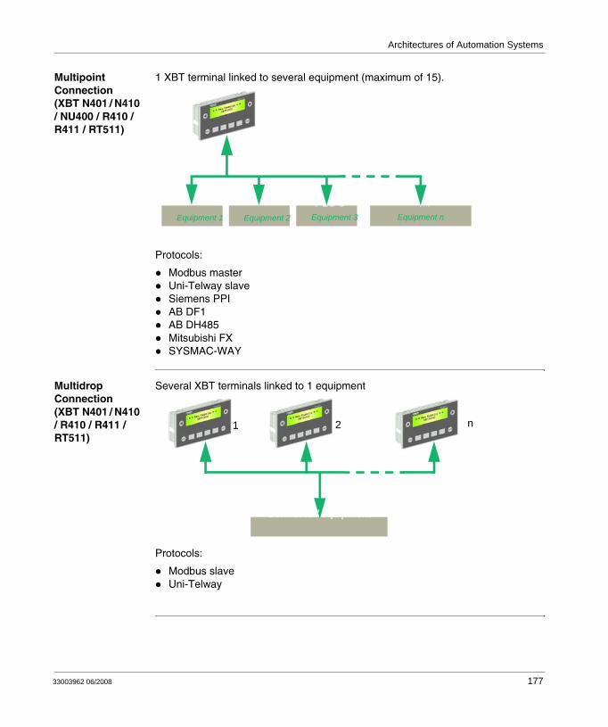
Architectures of Automation Systems
Multipoint Connection (XBT N401 / N410 / NU400 / R410 / R411 / RT511)
1 XBT terminal linked to several equipment (maximum of 15).
Protocols:
Modbus masterUni-Telway slaveSiemens PPIAB DF1AB DH485Mitsubishi FXSYSMAC-WAY
Multidrop Connection (XBT N401 / N410 / R410 / R411 / RT511)
Several XBT terminals linked to 1 equipment
Protocols:
Modbus slaveUni-Telway
PLC 1 PLC 2 Other equipment PLC 3Equipment 1 Equipment 2 Equipment 3 Equipment n
n2
Connected equipment
1
33003962 06/2008 177

Architectures of Automation Systems
178 33003962 06/2008
Glossary
alarm panel Information panel displayed when an alarm occurs on the automation system.An alarm panel is displayed by the automation system, when the associated boolean variable changes.It is generally used to provide to the operator all the information and the description of the actions he has to do, in order to deal with the current alarm.
alarm table An alarm table is a communication table that contains only words related to alarm functions.Each bit of alarm words can be associated to an alarm.The equipment can use it to signal to the terminal that an alarm has occurred.The terminal can use the status words of the alarm table to report to the equipment that the operator has acknowledged an alarm.
alphanumeric characters (A-Z) and numbers (0-9)
alphanumeric display units
These are only capable of displaying characters (with a font resolution usually 5x7 pixels). The characters are physically separated from one another.
alphanumeric terminals
These are equipped with alphanumeric display units or matrix display units used in character mode only.
animated HMI object
Object which representation and behavior depends on operator actions or on variables belonging to an equipment or to the terminal.
application Please refer to HMI application.
A
33003962 06/2008 179
Glossary
application browser
Structure tree representing the HMI application. The application bar is located at the left of the Vijeo Designer Lite user interface.
application panel An application panel can be displayed either by the operator or by the equipment of the automation system.It can display any information about the automation system.It allows the operator to input data into the automation system and to navigate from one panel to others.
automation system
all components (e.g. PLCs, HMI terminals, sensors, actuators) of an automated process
bitmap Image with fixed dimensions, which can be handled by a Windows software.
button Windows object used to perform the action described by the label or the symbol it containsA button is validated on touch screen or by pressing the enter key while the button is selected.
command table Part of the dialog table completed by the control system. This word list contains all the instructions passed to the terminal.
communication table
generic word for either a dialog table or an alarm table
configuration software
Vijeo Designer Lite is the configuration software that allows to create a HMI application and transfer it between a terminal and an equipment.
current language The language of the HMI application the designer is working on.
B
C
180 33003962 06/2008
Glossary
default terminal language
The HMI language used by the terminal when it is powered on.
demo version Version of Vijeo-Designer Lite used to demonstrate the configuration software.This version does not allow any transfer of the HMI application between the Vijeo-Designer Lite software and an XBT terminal.
designer Please refer to HMI designer.
dialog application
Set of data, necessary and sufficient to describe the behavior of a terminal during operation. Vijeo Designer Lite is the only tool that can be used to create this type of application for Schneider Electric terminals.
dialog table A dialog table is a communication table that can contain words related to any function of the terminal.A dialog table can include an alarm table.The purpose of a dialog table is to exchange data or orders between the terminal and the connected equipment.
download Transfer of an HMI application from an XBT terminal to Vijeo-Designer Lite.
dynamic function keys
These keys are placed on the front face of a terminal and their behavior depends on the displayed panel.You can set different function to them (e.g. panel access, command functions, object selection).
equipment Any device (generally a PLC) which communicates with a terminal.
external variable Variable which belongs to an equipment.
D
E
33003962 06/2008 181
Glossary
firmware This is the terminal on-board software. It comprises mainly the BIOS and the loader used to communicate with Vijeo-Designer Lite.
HMI human machine interface
HMI application Names all the data necessary to describe the behavior of an HMI terminal in the operating mode.Vijeo Designer Lite is the configuration software that allows to create an HMI application.
HMI designer (or designer)
The person who designs an HMI application using Vijeo Designer Lite.Even if there is no particular training to use Vijeo-Designer Lite, some skills in process automation are recommended to create a application.
HMI language An HMI application can be designed in several different languages. Each of these languages is an HMI language.
HMI object (or object)
The smallest element contained in a panel. Can be either an animated or an not-animated HMI object.
HMI operator (or operator)
The person who uses an HMI terminal in operation mode, in order to control and lead an automated installation or machine.An operator is a person who does not have any specific skill in process automation or computer science.
HMI terminal (or terminal)
Electronic terminal used by operators to control an automation system.An HMI terminal is mainly used to display information and alarms from the automation system, to allow the operator to input some parameter values into the automation system, and to control it.Basically, a terminal replaces former control panels that were mainly made of push buttons, lamps, indicators and measurement devices.
F
H
182 33003962 06/2008
Glossary
internal variable Variable which belongs to the terminal.Some internal variables provide services (like date/time) that can be used by the HMI designer without any restriction, as if they were PLC/equipment variables.
link HMI object contained in a panel used to access application panels or system panels (navigation links) or to perform command functions (command links).
loader Part of terminal firmware responsible for handling communication with Vijeo Designer Lite to transfer a application in one direction or the other. Its role is also to store application data, sent by Vijeo Designer Lite, in the terminal memory.
Magelis Generic commercial name of the all range of Schneider HMI terminals.
matrix display units
These consist of a continuous matrix of pixels, enabling the display of characters in different fonts and sizes, and also basic graphics. The technology and resolution of these display units is, however, too low for them to be considered true graphic display units.
matrix touch screen (or touch screen)
Transparent sheet stuck on a display, composed of a matrix of areas and sensible to operator action on it.
menu Title, located in a menu bar, allowing by selection to access a list of menu items. Each of these menu items is associated with a function.
mode of operation
There are 2 modes of operation:operating modetransfer mode
I
L
M
33003962 06/2008 183
Glossary
not-animated HMI object
Object which representation is constant. It is always displayed exactly as it has been configured.
object Please refer to HMI object.
operating mode A terminal´s mode of operation in which the terminal communicates with one or several equipment of an automation system.This is the normal operating mode of a terminal, when it uses the HMI application. The operator generally uses the terminal in this operating mode. Please refer to transfer mode.
operator Please refer to HMI operator.
optimum version Version of a terminal that can only be connected to some of the Schneider PLCs.Main characteristics:
just enough featuresexternal 5 VDC power supply (mainly provided by the PLC)1back-light color
panel A terminal can display a panel. Its size can be larger than the terminal display. In this case, the terminal allows using the scrolling to move the visible part of the panel.A panel can contain not-animated objects (e.g. background images, static texts) and animated objects (e.g. value displays, bar graphs).There are 3 different types of panels:
application panelalarm panelsystem panel
N
O
P
184 33003962 06/2008
Glossary
panel editor The panel editor displays the panel in WYSIWYG format (what you see is what you get). If the panel can not be displayed completely in the editor, a scroll bar is displayed.
pilot device A terminal can communicate with several control system-devices. Of these, only one is able to send commands to the terminal, and is capable of knowing its status; this device is called the pilot device. It contains the dialog table.
PLC programmable logic controller
protocol language of the communication between a terminal and equipment(s) connected to an industrial network
reference language
Language in which the designer constructs his application panels. By default, it is the installation language of the Vijeo-Designer Lite programming software.
service keys Keys on the keypad necessary for certain terminal functions (scrolling, selecting fields, data input, requesting a menu, etc.).
standard version Version of a terminal with standard functionality.Main characteristics:
external 24 VDC power supplypoint to point and multi-point connection1 back-light color
static function keys
Keys placed on the front face of a terminal.Their behavior is the same for the whole application.You can set different functions to them (e.g. panel access, command functions).
status bar Zone located at the bottom of a Windows window. It is used to indicate the state of the application or active element to the developer.
status table Part of the dialog table completed by the terminal. This word list represents the terminal status.
R
S
33003962 06/2008 185
Glossary
system panel A system panel is a pre-built, ready to use panel, which is systematically embedded into an HMI application.A system panel can be displayed either by the operator or by the equipment of the automation system, or by the terminal itself.It informs the operator about system or automation errors by a system popup panel.It allows the operator to change some terminal parameters (e.g. date, HMI language) and to navigate from one panel to others.
terminal Please refer to HMI terminal.
third party Indicates the fact that it is not a Schneider product.As an example it can be used for:
third party protocolthird party PLC
thumbwheel edition
Rudimentary edition mode based on the same principle as mechanical thumbwheels: selection of the digit to be modified by means of the horizontal arrow key(s), then selection of the digit value by means of the vertical arrow key(s).
touch screen Please refer to matrix touch screen.
transfer mode A terminal´s specific mode of operation in which the terminal is able to communicate with the configuration software to transfer an HMI application.The HMI designer mainly uses the terminal in this mode of operation. Please refer to operating mode.
tree structure Structure representing the application panels and the links between them. By extension, this window is used to represent the structure of all types of panels.
universal version Version of a terminal that can be connected to Schneider and third party PLCs in point to point as well as multi-point.Main characteristics:
external 24 VDC power supplypoint to point and multi-point connectionlight indicators
T
U
186 33003962 06/2008
Glossary
3 back-light colorsperipheral connection (printer)
upload Transfer of an HMI application from Vijeo-Designer Lite software to an XBT terminal.
user Either an operator or a designer (when it is not necessary to make the distinction).
variable Storage element containing a value evolving during the time. Can be either a internal variable or an external variable.
variable field Area on a panel configured to display an item depending on the value of a variable in the connected equipment.
version There are 3 terminal versions:please refer to optimum versionplease refer to standard versionplease refer to universal version
Vijeo-Designer Lite
Configuration software for the low end Magelis range. It replaces the XBT-L1000 software.
WYSIWYG What You See Is What You Get.
XBT Any HMI terminal (when it is not necessary to make the distinction).
V
W
X
33003962 06/2008 187

Glossary
188 33003962 06/2008
CBAIndex
Aalarm
buzzer, 120alarm list, 119, 120alarm log, 121, 156
clearing, 156display, 156principles, 156
alarm management, 119alarm panels, 154
acknowledgment, 120advantages in operating mode, 118appearance types, 119display, 121display priority, 119displaying, 154ignoring alarms, 155log, 121, 156objective, 118principle, 118principles, 118storage principle, 120viewing, 154
alarmsobjective, 118
appearance types, 119application, 162application panels
definition, 113display, 114principle, 113
applications, 94
33003962 06/2008
automation system architecturesmulitipoint connection, 177multidrop connection, 177point-to-point connection, 176
Bblank labels, 61button object, 139
Ccable, 106cabling, 71cancelling an edition, 150characteristics, 20, 21commands
impulse, 136toggle, 137
confirming an edition, 150connection
multidrop, 177multipoint, 177to a PC, 71
connectors, 38control elements, 34controlling automation system, 110
189
Index
Ddate and time, 128
display format, 128input, 128
dialog tableexchanging data via, 163
display of a panel, 114display of an application panel
on power up, 114dual labelled keys, 98dynamic function keys, 139
Eedition
cancellation, 150confirmed, 150report, 152
environmental influences, 20exchanging data via the dialog table, 163
Ffunction keys
dynamic, 39static, 39
functional command linkrepresentation, 141
functional link, 139functions
of keys, 98of touchscreen, 98XBT terminals, 93
HHMI language selection, 127human/machine dialog, 94
Iimpulse commands, 136input
exit on time out, 151of a value, 148
190
input/modification of a value, 146insert label XBT N, 48insert label XBT R, 50insert label XBT RT, 52
Kkey functions, 98keys, 34, 39
Llabel
insert label XBT N, 48insert label XBT R, 50insert label XBT RT, 52
language, 127LED
communication, 106LED functions, 101LEDs, 34line parameters, 130
error counters, 130log file, 156
Mmanaging alarms, 119material, 20MiniDIN, 38mode of operation
selection, 107modes of operation
operating mode, 106, 122transfer mode, 106, 109
mounting, 20
Ooperating elements, 34operating mode, 106, 110operation mode
selection, 107
33003962 06/2008
Index
Ppanels, 34password-protection, 131PC
connection to PC, 71PLC architectures, 175polling times, 28printing, 158
alarm log, 160as a data stream, 159principles, 158
printing blank labels, 61process commands
via function keys, 144via functional links, 139
product reference, 129protecting the terminal, 131protocols, 175
RRJ45, 38
Sscrolling within panels, 124selecting an edition field, 146
by the operator, 146by the pilot equipment, 147
selecting mode of operation, 107setting the display parameters, 126standards, 20structure of XBT applications, 94SubD25, 38system panels, 122, 123
definition, 122principle, 122
Ttemperature, 20terminal self-test, 174
continuous, 174on power-up, 174
33003962 06/2008
time outinput mode, 151
toggle commands, 137touchscreen functions, 98transfer mode, 109transferring software applications, 108
Wword
report, 152
XXBT NU400
polling times, 28
191

Index
192
33003962 06/2008