magnetek expansion elementspricebook.magnetek.com/pdfs/conductor bar systems/brochures...line...
TRANSCRIPT
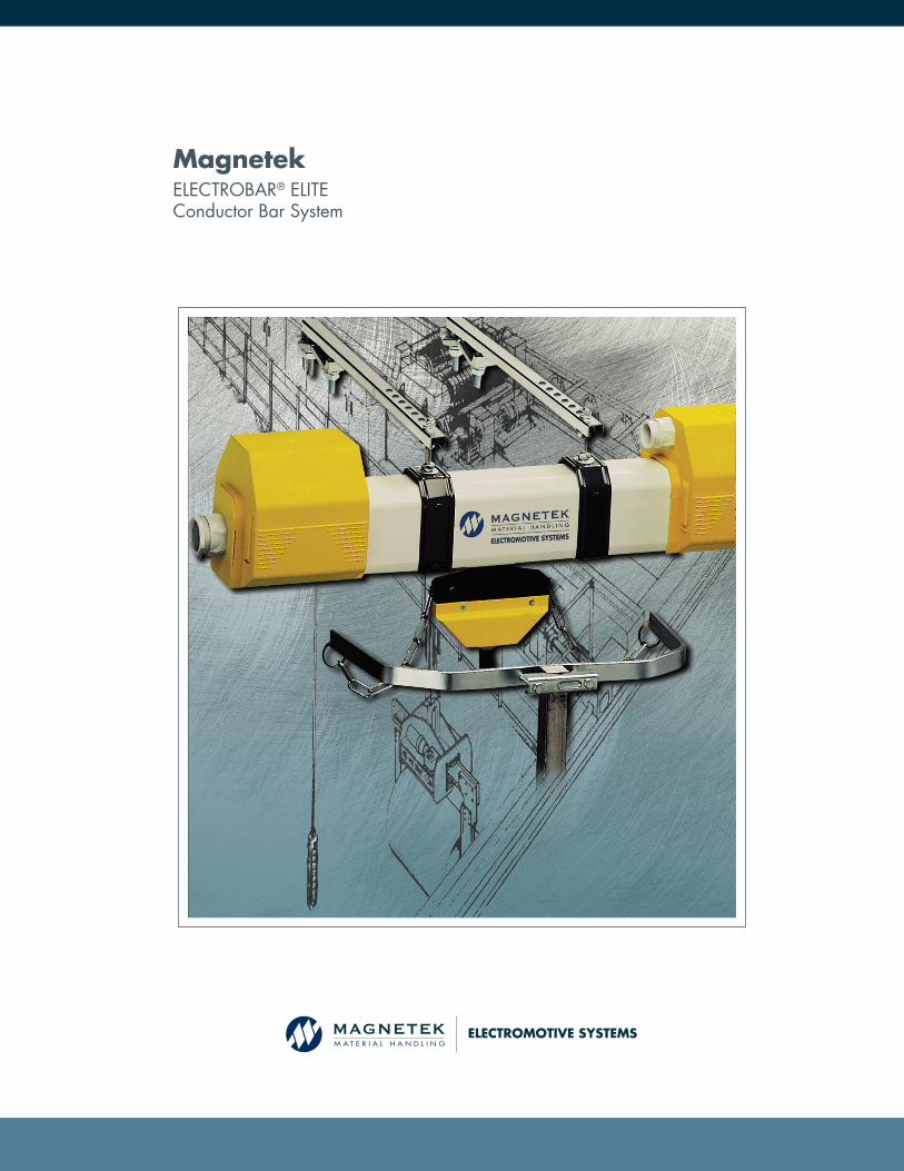
MagnetekELECTROBAR® ELITEConductor Bar System
ELECTROMOTIVE SYSTEMS
EXPANSION ELEMENTS

ELECTROBAR® ELITE ENCLOSED CONDUCTOR BAR SYSTEMS
Magnetek proudly offers ELECTROBAR® Elite, our most advanced conductor bar system. The collector
trolley and conductors are captured inside the line element extrusion and can’t be disengaged. The
collector trolley is advanced with a chain which tolerates large movements lateral to the direction of
motion. The system is simple to install, with only one “stick” to hang and align.
• Electrobar Elite reduces installation time when compared with traditional conductor bar systems.
Maintenance requirements are minimized, providing lower installation and lifetime maintenance costs.
• System components are lightweight and rigid, allowing a single person to assemble the system.
• Line elements are easily slipped into the snap-in hangers, which mount with one threaded rod to the hanger bracket.
• Joint covers, power feeds and end caps simply snap together over the line elements. Much of the assembly is done by hand, using a minimum number of tools.
• Line elements are connected with torque limiting bolts whose heads twist off when enough torque has been applied. This assures proper connection of conductors with smooth transitions from section to section for the collector brushes.
• Collector brushes are normally serviced by removing the trolley from the end of the system. The brushes are easy to remove and put back into the trolley, allowing a rapid return to service after maintenance. The collector assembly can only be put back into the line element in one orientation, preventing cross connecting power and ground.
• Compact design allows installation in tight spaces where other systems will not fit.
• No expansion joints are required in systems under 460 feet.
• Low friction collectors ease movement of workstation bridge cranes.
• IP23 rated so it is finger safe and resistant to rain at up to a 60 degree angle from vertical.
• Rubber dust exclusion strips are available to minimize contamination of conductors through the line element trolley gap.
• High speed collectors available for speeds exceeding 325 fpm.
• Standard line element operating temperature range -20°C to 55°C.
• High temperature line elements available for temperatures above 55°C to 75°C.
• Curved elements available with minimum 32” radius.
• Ventilated line elements prevent condensation build up.
• Trolley introduction gates ease maintenance of collector trolleys when three or more bridges are used on a single crane runway.
LOWER TOTAL SYSTEM COST — EASY TO INSTALL AND MAINTAIN
MAXIMUM VERSATILITY
2Many parts of the Electrobar Elite system are made from plastic insulating materials. The insulating covers for normal temperature use are made of PVC, the plastic hangers are made from thermoplastic materials as are the plastic parts of the collectors. If your application uses materials or chemicals that can evaporate or get into the air and onto the conductor bar parts, please consult with Magnetek about the suitability of this product in your environment.

LINE ELEMENTS
4-POLE LINE ELEMENTS
Catalog Number Description
Length
Weight Lbs.Meters Feet
FM-4204FM-4203FM-4202FM-4201
20 Amp, 4-Pole Line Element
4321
13.1239.8436.5623.281
15.0011.257.503.75
FM-4604FM-4603FM-4602FM-4601
60 Amp, 4-Pole Line Element
4321
13.1239.8436.5623.281
15.8811.917.943.97
FM-4104FM-4103FM-4102FM-4101
100 Amp, 4-Pole Line Element
4321
13.1239.8436.5623.281
17.6413.238.824.41
FM-4134FM-4133FM-4132FM-4131
130 Amp, 4-Pole Line Element
4321
13.1239.8436.5623.281
21.1615.8710.585.29
FM-8284-TRFM-8283-TRFM-8282-TRFM-8281-TR
200 Amp, 4-Pole Line Element
4321
13.1239.8436.5623.281
31.7223.7915.867.93
STANDARD FEATURES & BENEFITS• Operating temperature range -20°C to 55°C.• Collector trolley captured by line element and can’t be disengaged.• Snap together covers, power feeds and hangers.• Lightweight, rigid construction.• Ease of installation, lower total system cost, and low maintenance.• Improved safety (finger safe rating of IP23).
Item Page Number
1. Line Element 3
2. End-Line Power Feed 4
3. In-Line Power Feed 4
4. Joint Cover 4
5. End Cap 4
6. Sliding Hanger 5
7. Anchor Hanger 5
8. Mounting Bracket 5
9. Collector 6
10. Tow Bracket 6
11. Dust Exclusion Seals (pictured pg. 7) 7
12. Transfer Funnels (pictured pg. 7) 7
13. Expansion Element (pictured pg. 8) 8
8
2
910
1
63
7
5
4
1. 4-POLE AND 5-POLE LINE ELEMENTS
5-POLE LINE ELEMENTS
Catalog Number Description
Length
Weight Lbs.Meters Feet
FM-5204FM-5203FM-5202FM-5201
20 Amp, 5-Pole Line Element
4321
13.1239.8436.5623.281
15.8811.917.943.97
FM-5604FM-5603FM-5602FM-5601
60 Amp, 5-Pole Line Element
4321
13.1239.8436.5623.281
16.7612.578.384.19
FM-5104FM-5103FM-5102FM-5101
100 Amp, 5-Pole Line Element
4321
13.1239.8436.5623.281
18.4813.869.244.62
FM-5134FM-5133FM-5132FM-5131
130 Amp, 5-Pole Line Element
4321
13.1239.8436.5623.281
23.8017.8511.905.95
FM-8285-TRFM-8289-TRFM-8286-TRFM-8287-TR
200 Amp, 5-Pole Line Element
4321
13.1239.8436.5623.281
37.0427.7818.529.26
• Line Elements are constructed of self-extinguishing PVC with copper conductors. 20 Amp Line elements use steel conductors.
• Maximum rated operational voltage 600 volts, 460V for high temperature line elements.
3
4
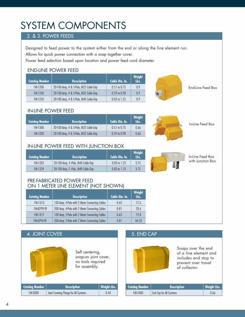
SYSTEM COMPONENTS2. & 3. POWER FEEDS
Designed to feed power to the system either from the end or along the line element run.Allows for quick power connection with a snap together cover.Power feed selection based upon location and power feed cord diameter.
END-LINE POWER FEED
Catalog Number Description Cable Dia. In.Weight
Lbs.
FM-1200 20-100 Amp, 4 & 5-Pole, M25 Cable Grip 0.51 to 0.75 0.9
FM-1230 20-100 Amp, 4 & 5-Pole, M32 Cable Grip 0.59 to 0.98 0.9
FM-1250 20-100 Amp, 4 & 5-Pole, M40 Cable Grip 0.83 to 1.25 0.9
IN-LINE POWER FEED
Catalog Number Description Cable Dia. In.Weight
Lbs.
FM-1300 20-100 Amp, 4 & 5-Pole, M25 Cable Grip 0.51 to 0.75 0.66
FM-1330 20-100 Amp, 4 & 5-Pole, M32 Cable Grip 0.59 to 0.98 0.66
IN-LINE POWER FEED WITH JUNCTION BOX
Catalog Number Description Cable Dia. In.Weight
Lbs.
FM-1332 20-100 Amp, 4 -Pole, M40 Cable Grip 0.83 to 1.25 3.75
FM-1329 20-100 Amp, 5 -Pole, M40 Cable Grip 0.83 to 1.25 3.75
PRE-FABRICATED POWER FEED ON 1 METER LINE ELEMENT (NOT SHOWN)
Catalog Number Description Cable Dia. In.Weight
Lbs.
FM-1313 130 Amp, 4-Pole with 2 Meter Connecting Cables 0.63 17.6
FM-8299-TR 200 Amp, 4-Pole with 2 Meter Connecting Cables 0.81 28.6
FM-1317 130 Amp, 5-Pole with 2 Meter Connecting Cables 0.63 19.8
FM-8294-TR 200 Amp, 5-Pole with 2 Meter Connecting Cables 0.81 34.32
End-Line Feed Box
In-Line Feed Box
In-Line Feed Box with Junction Box
4. JOINT COVER
Catalog Number Description Weight Lbs.
FM-2000 Joint Covering Flange for All Systems 0.44
Self centering, snap-on joint cover, no tools required for assembly.
5. END CAP
Catalog Number Description Weight Lbs.
FM-2400 End Cap for All Systems 0.66
Snaps over the end of a line element and includes end stop to prevent over travel of collector.

Horizontal Web Mount
SYSTEMS COMPONENTS
8. HANGER MOUNTING BRACKETS
6. & 7. MOUNTING HANGERS
Mounting Brackets
Anchor Hangers secure the line element to the structure.Galvanized steel construction and premounted M8 x 60 bolt with (2) anchoring screws.
Galvanized steel construction and premounted M8 x 60 bolt.Snaps onto line element.
SLIDING HANGERCatalog Number Description Weight Lbs.
FM-1510 Snap-In Hanger, New Style 0.22
Two (2) required for 20 to 130 Amp, 4 meter line elements.Three (3) required for 200 Amp, 4 meter line elements.
ANCHOR HANGERCatalog Number Decsription Weight Lbs.
FM-1500 Anchor Hanger, New Style 0.22
Two (2) anchor hangers required on systems with an expansion.
WEB MOUNTING BRACKETS
Catalog Number Description “X” Dimension
Weight Lbs.
BKS-W15-G Galvanized, Web Mounted, 15 in. 11 in. 1.5
BKS-W18-G Galvanized, Web Mounted, 18 in. 14 in. 1.9
BKS-W24-G Galvanized, Web Mounted, 24 in. 20 in. 2.2
FLANGE MOUNTING BRACKETS
Catalog Number Description “X” Dimension
Weight Lbs.
BKS-F18-G Galvanized, Flange Mounted, 18 in. 18 in. 2.2
BKS-F24-G Galvanized, Flange Mounted, 24 in. 24 in. 2.7
To order Flange Mount Brackets with two mounting clamps, add “A” after F18 or F24.Horizontal Flange Mount
WORKSTATION BRIDGE CRANE MOUNTING BRACKETS
Catalog Number Description “X” Dimension
Weight Lbs.
BKS-GBL-2K Galvanized, for 4 in. x 4 in. tube 15 in. 3.5
BKS-GBL-4K Galvanized, for 5.5 in. x 4.5 in. tube 18 in. 4.5
BKS-GBL-4K2 Galvanized, for 6 in. x 6 in. tube 18 in. 4.5
5
“X”
Workstation Bridge Crane Bracket
6
COLLECTOR ASSEMBLIES9. STANDARD (RIGID) COLLECTOR TROLLEY
Collector selection based on amperage requirements.The collector assembly can be installed only in one orientation to the line element, insuring the ground conductor and the ground collector brush are always together.The brushes snap into the collector assembly for quick and easy replacement.Factory stocked collectors come standard with (1) meter of cable and are for systems without curves or dust protection.
Single Collector
Double Collector
Triple Collector
RIGID COLLECTOR TROLLEY FOR 4-POLE SYSTEMS
Catalog Number Description Amp Rating
Weight Lbs.
FM-2043-1M Single Collector Trolley with 1 Meter Cable 40 Amp 1.32
FM-4047-1M Double Collector Trolley with Two 1 Meter Cables 80 Amp 2.42
FM-5049-1M Triple Collector Trolley with Three 1 Meter Cables 120 Amp 3.52
FM-4514 Cleaning Collector Trolley (not pictured) 0.88
RIGID COLLECTOR TROLLEY FOR 5-POLE SYSTEMS
Catalog Number Description Amp Rating
Weight Lbs.
FM-2051-1M Single Collector Trolley with 1 Meter Cable 40 Amp 1.32
FM-4051-1M Double Collector Trolley with Two 1 Meter Cables 80 Amp 2.42
FM-5059-1M Triple Collector Trolley with Three 1 Meter Cables 120 Amp 3.52
FM-4525 Cleaning Collector Trolley (not pictured) 0.88
Collectors shown are for standard applications composed of straight line elements. For all other applications, please consult the factory for an application specific quotation.
REPLACEMENT PARTSCatalog Number Description
FM-0022 Carbon Brush
FM-0118 Brush for Cleaning Collectors
10. TOW BRACKETS
Tow Brackets (standard carriers) provide the mechanical link between the collector trolley and the moving equipment.Galvanized steel brackets to be mounted onto a round tow bar 0.79’’ (20mm) to 1.97’’ (50mm) or a square tow bar 0.19’’ (20mm) to 1.57’’ (40mm). Junction boxes are available for tow brackets. Consult the factory.
Catalog Number Decsription Weight Lbs.
FM-1600 Tow Bracket for Single Trolley 1.3
FM-1610 Tow Bracket for Double Trolley 2.4
FM-1630 Tow Braket for Triple Trolley 5.7
Single Collector Tow Bracket
Double Collector Tow Bracket
Triple Collector Tow Bracket

7
TRANSFER FUNNELS12. TRANSFER FUNNEL LINE ELEMENTS
SHORT FUNNEL ASSEMBLIESCatalog Number Description Amp. Rating
FM-2501 4-Pole 1 Meter Element Ground Right 20
FM-2502 4-Pole 1 Meter Element Ground Left 20
FM-2517 4-Pole 1 Meter Element Ground Right 60
FM-2518 4-Pole 1 Meter Element Ground Left 60
FM-2525 4-Pole 1 Meter Element Ground Right 100
FM-2526 4-Pole 1 Meter Element Ground Left 100
FM-2533 4-Pole 1 Meter Element Ground Right 130
FM-2534 4-Pole 1 Meter Element Ground Left 130
FM-2541-TR 4-Pole 1 Meter Element Ground Right 200
FM-2542-TR 4-Pole 1 Meter Element Ground Left 200
LONG FUNNEL ASSEMBLIESCatalog Number Description Amp. Rating
FM-2551 4-Pole 1 Meter Element Ground Right 20
FM-2552 4-Pole 1 Meter Element Ground Left 20
FM-2567 4-Pole 1 Meter Element Ground Right 60
FM-2568 4-Pole 1 Meter Element Ground Left 60
FM-2575 4-Pole 1 Meter Element Ground Right 100
FM-2576 4-Pole 1 Meter Element Ground Left 100
FM-2583 4-Pole 1 Meter Element Ground Right 130
FM-2584 4-Pole 1 Meter Element Ground Left 130
FM-2591-TR 4-Pole 1 Meter Element Ground Right 200
FM-2592-TR 4-Pole 1 Meter Element Ground Left 200
• Transfer funnel is pre-mounted on 1 meter line element. Special lengths available upon request.
• Short funnels may be used for switch applications from 0.375’’ to 1’’ gap.
• Long funnels may be used when gap distance exceeds 1’’.• Special collector trolleys and tow brackets are required. Contact factory.• Funnels designed to accommodate ground to the right or left.• IP23 “finger safe” Rated.
11. DUST EXCLUSION SEALS
Rubber dust exclusion seals are available for line elements, in-line power feeds, joint covers, curves, trolley inlet gates and expansions. They are not used for end of line components, since the trolley does not pass through them. The catalog number is made by adding a -LV to the end of the standard catalog number. For example, a 20 Amp line element with dust exclusion seals is FM-4204-LV instead of the standard FM-4204. The seals can be added to stocked line elements, which allows good turnaround time for systems requiring dust exclusion. Suitable for use up to 55°C.
Silicone grease is used on the inside of the rubber seals to ease the travel of the collector trolleys.
DUST EXCLUSION SEALS
Catalog Number Decsription Weight Lbs.
FM-0287 Dust Seal Grease 0.5
YOUR ONE-STOP SOURCE FOR MATERIAL HANDLING CONTROL SOLUTIONS
N49 W13650 Campbell Drive
Menomonee Falls, WI 53051
Toll-Free Phone 800.288.8178
Toll-Free Fax 800.298.3503
Phone 262.783.3500
Fax 262.783.3510
Canada Facility
4090B Sladeview Crescent
Mississauga, Ontario
L5L 5Y5 Canada
Phone 800.792.7253
Fax 905.828.5707
WWW.MAGNETEKMH.COM
MH471_Elite Bar Brochure
© Magnetek, Inc. 2015 04/15
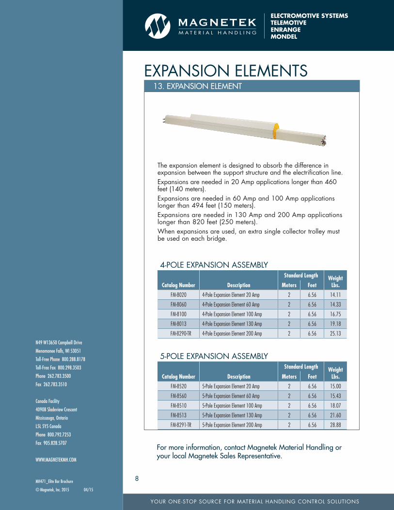
13. EXPANSION ELEMENT
The expansion element is designed to absorb the difference in expansion between the support structure and the electrification line.Expansions are needed in 20 Amp applications longer than 460 feet (140 meters).Expansions are needed in 60 Amp and 100 Amp applications longer than 494 feet (150 meters).Expansions are needed in 130 Amp and 200 Amp applications longer than 820 feet (250 meters).When expansions are used, an extra single collector trolley must be used on each bridge.
EXPANSION ELEMENTS
4-POLE EXPANSION ASSEMBLY
Catalog Number Description
Standard Length Weight Lbs.Meters Feet
FM-8020 4-Pole Expansion Element 20 Amp 2 6.56 14.11
FM-8060 4-Pole Expansion Element 60 Amp 2 6.56 14.33
FM-8100 4-Pole Expansion Element 100 Amp 2 6.56 16.75
FM-8013 4-Pole Expansion Element 130 Amp 2 6.56 19.18
FM-8290-TR 4-Pole Expansion Element 200 Amp 2 6.56 25.13
5-POLE EXPANSION ASSEMBLY
Catalog Number Description
Standard Length Weight Lbs.Meters Feet
FM-8520 5-Pole Expansion Element 20 Amp 2 6.56 15.00
FM-8560 5-Pole Expansion Element 60 Amp 2 6.56 15.43
FM-8510 5-Pole Expansion Element 100 Amp 2 6.56 18.07
FM-8513 5-Pole Expansion Element 130 Amp 2 6.56 21.60
FM-8291-TR 5-Pole Expansion Element 200 Amp 2 6.56 28.88
8
For more information, contact Magnetek Material Handling or your local Magnetek Sales Representative.