magnetic amplifiers - vtechworks.lib.vt.edu used the magnetic amplifier. wartime research projects...
TRANSCRIPT
AN INTRODUCTION TO THE STUDY OF
MAGNETIC AMPLIFIERS
John Petersen Gordon Jr1
Thesis submitted to the Graduate Faculty of the
Virginia Polytechnic Institute
in candidacy for the degree of
MASTER OF SCIENCE
in
Electrical Engineering
June, 1959
Blacksburg, Virginia
2
TABLE OF CONTENTS
INTRODUCTION • • • • • • • • • • • • • • • • • • • • • •
Page
6
Definitions and History • • • • • • • • • • • • • • • 6
Characteristics or Magnetic Amplifier
Core Materials ••••• • • • • • • • • • • • • •
II. THE BAS IC SATURABLE REACTOR • • • .. . . • • • Voltage and Flux Relations • • • • • • •
Simple Saturable Reactor Operations with
Open Control Circuit • • • • • • • • •
Simple Sat'l.1l"El.ble R~actor Operations with
• • • • • • . . . . ... •· . . . . .
Control Voltage Applied , • • •
III. THE SERIES CONNECTED SATURABLE REACTOR
. . . . . .. . . . • • • • • • • • •
Series Connected Seturable Reactor with Low
s 12
12
14
16
19
Control Circuit Impedance • • • • • • • • • • • • 19
Law of Equal Ampere Turns • • • • • • • • • • •••
Saturable Reactor Operation Under Forced
Magnetization • • • • • • ' . . . . . . . . . . . IV. THE PARALLEL CONNECTED SATURABLE RF.ACTOR • • • • • • • • V • STEADY STATE SATURABLE RE.ACTOR CHARACTERISTICS • • • • •
Control Characteristic • • • •
Voltage-Current Characteristic • •
• •
• • • • • • • • •
• • •••• • • • Power Gain • • • • • • • • • • • • • • • • • • • • • Current Gain • • • • • • • • • • • • • • • • • • • •
28
31
35
35
39
1 .. 2
42
VI.
vn.
VIII.
IX•
;
FEEDBACK IN MAG'METIC AMPLIFIERS ••••• • • • • .. . . . Page
4.3
Magnetic Feedback • • • • • • • • • • • • • • • • • • 43
Control Characteristic for Feedback
F MCtors of Unity or Above • • • • • • • • • • • • •
Feedback by Self'...Saturation • • • • • • • • • • • • , •
Self-Saturation in Two Core ~tic Amplifiers .•.•..•
BIBLIOGRAPHY • • • • • • • • • • • • • • • • • • • .. . . . Literature Cited •
Literature Examined
ACKNOWLEDGEMENTS • • •
• • • • • • • • • • • •
• • • • • • • • • • • ••
• • • • • • • • • • • • VITA • • • • • • • • • • • • • • • • • • • • •
• • • • • • -. . . .. . . • • • • • •
• • • • • •
46
50
52
57
'57
59
62
63
4
LJST OF FIGURES
Figure
1. A typical dynamic hysteresis loop for Orthonol • • 2. An idealized hysteresis loop for utlle in aaturable
• • • •
Page
9
reactor and magnetic amplifier analysis " . • • • • • • ll
3. Basic sa.turable reactor circuit ••••••••• • • • • 13
4. Voltage and flux waveforms in a basic saturable
reactor eireui t with zero control current • •
5. Voltage and flux wavefonns in a basic sm.turable
_.. . . . . 15
reactor circuit vi.th applied control voltage • • • • • 17
6. Series oonneetfiitd saturable reactor • • • • • • • •
7. Series connected saturable reactor operation with
8.
zero control current • • • • • • • • • • • • •
Series connected saturable reactor operation with
control current • • • • • • • • .. . . . . . . . 9.. Series connected saturable reactor operation under
• • ••
• • • •
. .. . . forced magnetization conditions •• • • • • • • • • • •
10. Parallel connected saturable reactor . . .. • • • • • • • • 11 • Voltage, current, and flux wveforms for a parallel
20
22 '
29
32
connected saturable reactor • • • • • • • • • • • • • • 33
12. Simple control characteristic • • • • • • • • • • • • • • 36
13. A family of control characteristic curves draw for
the tbree excitation modes . . . . . . . .. . . . . . .
Page
14. (a) No-lead vol tage ... current characteristic
with load line • • • • • • • • • • • • • • • • • 40
(b) Voltage-current characteristic for load indicated
in (a) • .. • • • • • • • • • • • • .. • ,, • • • • 41
15. Magnetic runpl:!fier, series connected, with :magnetic
.feedback • • • • • • • • • • • • • • • • • • • • • 44
16. Relation between control eharacter:istics wi.th
and without feedback • • • • • • • • • • •
17. Magnetic amplifier with infinite gain ••••
. . .. . . • • • ii •
18. Magnetic amplifier with snap action • • • • • • • • • •
19. Basic single core self-saturating magnetic amplifier • • 20. Waveforms depicting the operation of a single
core self-saturating dev:tce • • • • •
21. Magnetic amplifier with selt'-saturation
• •
• •
... • • • • • • • • • ••
46
49
49
51
53
6
I. IIfrRODlJCTIOI
Definitions and Hlsto;rz
The magnetic amplifier.is a device using saturable reactors either
a.lone or in combination with other circuit elements to secure
anrplifioation.1 The be.sic element of the magnetic amplifier, the
saturable reactor, is an elec~romagnetic device employing one or
more nonlinear magnetic cores. This combination is used in alter-
nating current circuitry to secure amplification or control by
in.f'luencing the cort!I nonlinearity.2
The operation of a saturable reactor may be desori'bed brietly
on the basis of' two windings upon a ferromagnetic core.· One Yin.ding,
to which d-c is applied, is called the control winding. Tbs other is
connected into an a-e load circuit, and is known as the gate winding.
The d-e.applied to the control winding determines the degree of' core
saturation. The differential permeability of the core material is
dependent upon the degree of saturation, and since .the winding
impedance is a function of the differential permeability, it may be
said that the d-c applied to the control winding innuences the flow
of power in the a-c load circuit.
Many circuit a~ementa are possible using the basic element
just described. Pu.sh-pul.1 and polyphase connections are common,
while cascaded stages are frequently used to secure higher levels of
amplification. In addition, particular characteristics. in the
behavior of the device may be obtained through the introduction of
7
positive and negative fe$dback. Notable among these characteristics
is the bistable mode ehancterized by •on-off" operation.
The magnetic amplifier has been derived from a saturable reactor
first described by C. F. Burgess and B. Frs.nkent"eld in 1901. In a
patent issued to them in 1903 was described a method £or regulating
electric current by means of a variable inductance reaotor.3
It was not until 19161 despite some patent activity. that mu.ch
importance was attached to the potentialities of the device. In
that year E. F. W. Alexanderson used a sa.turable reactor in con-
junction Vlith a microphone to control the output of a 2•kw high
frequency alternator.4
During the period between World War I and World War II a
considerable number of patents vere issued for basic saturable
reactor circuits and elmnentary magnetic amplifiers. Despite this
activity, verr little was done in this country bl the application of
the device to commercial use. In Europe, pa.rt:teuls.rly Germany, the
potential of the magnetic amplifier was quickly recognized. Because
of the extreme reliability or the device. muoh of the German military
equipment used the magnetic amplifier.
Wartime research projects yielded much information about
magnetic core materials • On the basis of this, new core materials
with narrow, rectangular hysteresis loops were developed. The
developnents in magnetic :materials coupled with advances in metallic
rectifier design resulted in a vast amount of progress in the field
of magnetic amplifiers in the years :immediately after World War II.
,. •.
s
At the present time a great deal of work is being done in the
outlining ot the theory of magnetic amplifier operation. Up to
this point the operation of the magnetic amplifier bas been described
almost entirely in empirical terms.
The magnetic amplifier has found its way into a vast number
of' commercial awlioa.t:lons. '!'he reason for this activity lies in
the ma.ny characteristics of the magnetic a:m.plifier which .give it
distinct advantage over other amplifying devices. It is a unit
having extreme reliability, a. long life, ruggedness, no warm-up
time, high efficiency, a minimum of maintenance problems, and high
temperature capabilities.S The main disadvantage of' the device is
its slow response time. other disadvantages which m.s.y be overcome
in certain situations are the cost and size or the unit.
Cha.:ra.eteristics g! · !:f!gnetic Ampl:lf'ier Core M@;terialp.
The magnetic materials used in the construction ot magnetic
amplifie·rs are cha.ra.aterized by the abrupt change between the high
and low differential permeability regions of the dynamic hysteresis
loops. This abruptness lends itself to some simplifying ueumptions
that are adopted in many treatments" or magnetic amplifier theory.
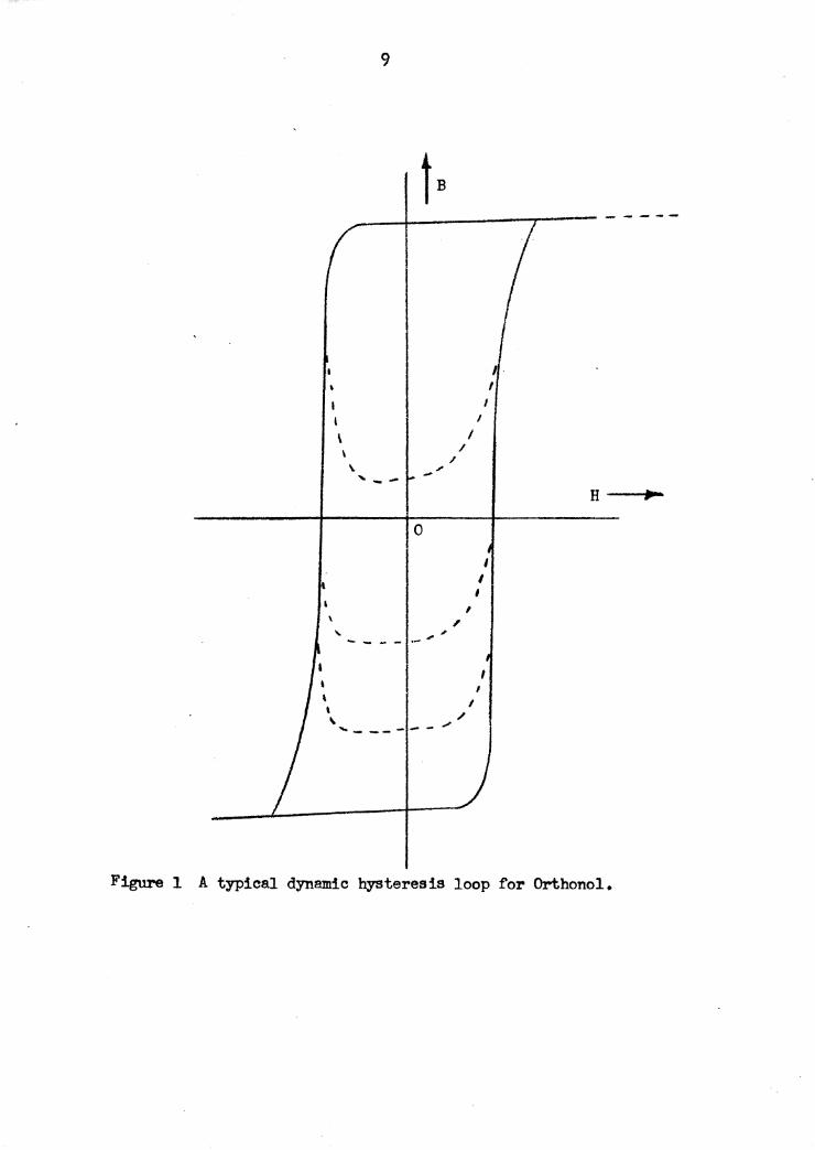
A hysteresis loop that is typical o:f' the materials us~d in magnetic
s.mplif'iera is shown in figure 1. The solid curve represents the
dynamic loop for a material known commercially as Orthonol.
The dotted portions of the curve in figure 1 depict the minor ·
hysteresis loops. These loops occur when an alternating magnetic
9
--+-------,--- - - - --
i. I
I I I
\ I \ I
I \ -,,,. , __
H ~
0
I I
' I \ , " ,,,. ... ----
I I
\ I
' / \ ...... _ --- -- ,,,,
Figure 1 A typical dynamic hysteresis loop ~or Orthonol.
10
field is superimposed upon a constant magnetic field and applied to
a ferromagnetic cere.6 It will .be seen later that the minor loops
of the hysteresis curve become an integral part of the theory ot saturable reactors and tnagnetic amplifiers •
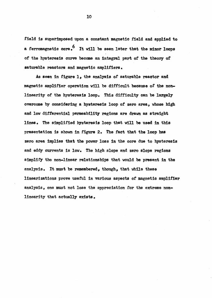
As seen in figure 11 the analysis of satu.rable reaetor aad
magnetic amplifier operation will be difficult because of the non-
linearity of the hysteresis loop. 1'his difficulty can be largely
overcome by considering a hysteresis loop of zero area, whose high
and low differential permeabilit,' regions are drawn as straight
lines• The simplified hysteresis loop that will be used in this
presentation is shown in figure 2. '!'he tact tbat the loop ha.I
zero area implies that the power loss in the core due to hysteresis
and eddy currents is low. 'rhe high slope and zero slope regions
simplify the non-linear relationships that would be present in the
analysis. It must be remembered, though, that 'While these
linearizations prove useful in various aspects or magnetic amplifier
analysis, one must not lose the appreciation .for the extreme non•
linearity that aetue.l.ly exists.
11
H ___ ...,._
-'---..!J-----
I I -Irr
-- ... ~IQ:-• ____ ..., - %AT.
Figure 2 An idealized hysteresis loop for use in saturable reactcr
and magnetic amplifier analysis.
12
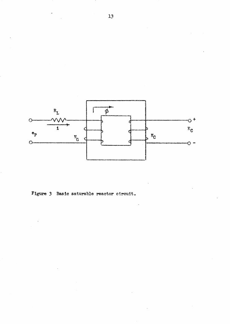
n. Tm BAS IC SATURABLE REACTOR
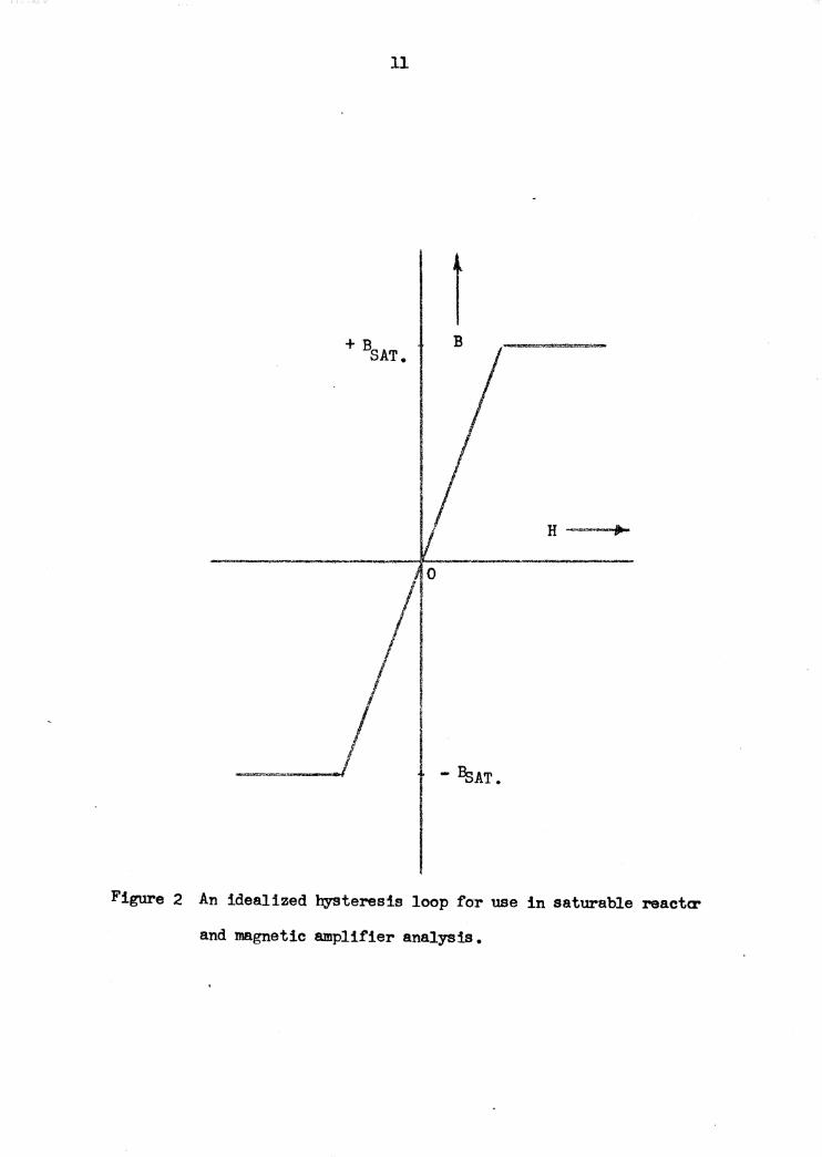
!ol\U! and DB wa»ont Aa understanding of the basic voltage and n.mr: relathmsh!ps
is nece1sa17 :tn the stv.dy ot aaturable 1"8&otor eperat:!on. To
establish these re1atiou 1 consider a o!rcuit suah u that shown in
figure 3. A gate wtndinl with 10 turns is wound on one leg, am a
eontrol vinding with 11 turns is wound 011 the other leg of a eon
made ot arbi t1'8!7 material. The application ot ltiMhhoffts voltage
law to the gate circuit with the control circuit open Ji•lda the
equation ep = l.J(L + MG J o/Jt 1
Equation l will haw putioular eignif1.cance with respeet to
eaturable reactor theoJ.'7 when it is integrated between the lind:ta of
t1 and ti• The reeulting equation 2 deaeri'bes the wlt-aeec.Jnd, or
flux linkage relationahip in the circuit. J~p J t = 11:~i. ... 1<L Jt + Nc:s ( cb,_ - <h,) 2 t, '(I
Equation 2 il:l.dicatea that the area under the volt-eecon4 eane tor
the load resistance plus the area under the volt-second or :fl.a,
linkage aul"fe of the gate voltage ut be equal to t.he area under
the source VGl. t-aeoond curve. The area U1lder the flux lbka.p ·O't11'V'e
for the gate winding ts limited. by allowable range of core tl:ux.,
The variation in. flu as dictated by the bJaterest1 loop la limited
to + C}? 4J, to - ~s J the po1it:b1e and negatiw val.ma of aaturatien
13
~ ...... I ~ i ¢ .,_ iZ /\/VV'- !) ~ 0 - ...,..
i ( ~ !) \!.;
NG ( ~Ne ~ .. - ---o-
~,,_~~ ............ ..._.-===-
Figure 3 Basic saturable reactor circuit.
14
flux. The applied voltage which will yield the maximum range of
flux variation is called the saturation voltage, an important
reactor characteristic. For applied vol ta.gas less than the
saturation voltage virtually all the voltage will be developed across
the gate winding with an almost negligible voltage developed across
the resistor (due to exciting current) • Should the applied voltage
be larger than the saturation voltage equation 2 indicate• that the
core will be saturated during the interval, and the applied voltage
will be developed across the resistor during this satuntion
interval. The presence ot voltage across the load resistance Jti1
indicates the exiStence of gate or load current.
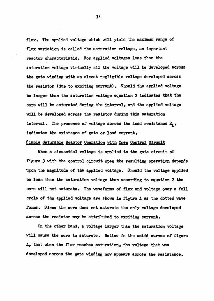
~imple Saturable Reactor !?l?eratipn ~Open Control Oircuit
When a sinusoidal voltage is applied to the gate circuit of
figure 3 with the control circuit open the resulting operation depends
upon the magnitude of the applied voltage. Should the voltage applied
be leas than the saturation voltage then according to equation 2 the
core will not saturate. The waveforms of flux and voltage over a :f'u1l
cycle o£ the applied voltage are shown in figure 4 as the dotted wave
forms • S inee the core does not saturate the only voltage developed
across the resistor may be attributed to exciting current.
On the other hand, a vo,lta.ge larger than the saturation voltage
will cause the core to saturate. Notice in the solid curves of figure
4, that vhen the nux reaches saturation. the voltage that was
developed across the gate winding now appears a.cross the resistance.
15
voltage
voltage
Figure 4 Voltage and flux waveforms in a basic saturable reactor
circuit with zero control current.
'16
This is :bl complete &pUl9nt .Wf.tb equation 2. The :.lnte"91 tdlen
the eore is saturated. is rete:rred to as the aaturation int•""'1~ and
is o~ter!sed bf the existenc• of OU1"!'$'.1'it :bl the. gate ·cmld..t.
In tl,are 4 this ta htd1eated by the voltage ao1.'0ll1 the' 'HBU~~·•
'fb.e :point at· which the core n.tul'atea, intt:lattng the •• c_..,,..• wawfom, u i'l"equent11 referNd to u the tiring tmal• 1 o<.. •
Thia ta due to the eblila:d.ty to the f'irtng of a ~tron.
Spl?J! fttnbJ.e BtMt!t Oa!r&titne !.Ul! h!V!I tdtaa &liil•I The application of a d.o ocmtrol "Vt>liage :reftl.ta in a·tlu
variation that follow one et the minor loops n.eh u tho• l9howa
in figve 1. Vith an a.,. voltage applied eqval to the aatU!'atioa
voltage the oore is made to aatUrate u a result of the 4...o t1e14.
The fl:ux wavetom, in.dinting saturation of the· core• :ls shown in
figure 5. .A.ga!n, while the core is satUJ'ated ~t eldate bl the
gate cd.reuit. hrtna the second halt cyol.e1 at angle· (oc. +n)
ratH.anas while the eosre dou not 1aturate 1 the:N ii no &ppt"fftable . . . . .
cha!Jge in tl.u. Bene• t• vol tap will appear aareet the :resister
as bafere. hom this. it is seen that the averag• 'Value ot the gate
current depends upon the 11a1111itude ot the oont3l'CIJ1 CU1'1"8nt, The
control ClU'Nnt sets the level or the flux ftriatlort.
The reactor cd.rtnd.ta diacusaecl on the preceding papa were
introduced u simple U'l!lllplea of flux and voltage behavior in cirouttl
including reetangU].u hysteresis loop eot'8 materia.11. haetors ot this tor.m present serious disadvantages :ln.commenial mare due te
¢
~o /
-(ls
! ..(.
'
17
wt supply voltage
wt gate voltage
Figure 5 Voltage and flux waveforms in a basic saturable reactor
circuit with applied control voltage.

lS
the mutu&l induction between gate and control wil'ldbtgs. l'n its
praotical rorm the reactor utilizes two core aa•emblies with control
windings connected ao aa to eliminate &!fl' f'undalllental induced ve>l.tages
in the control cil'OU!t.
19
III. TJfE SERIES CONNECTED SATURABLE REACTOR
The form in which the more practical saturable reactor appean
is varied. As al.rea.dy' mentioned• the circuit ma.7 consist of two
complete core assemblies as ahoWn in figure 6. In addi ti.on the
circuit may be found in conjunction 'With a three-legged core. The
gate windings wound on the outside legs• and the control winding
on the center leg. The windings in aDY' case are wound in such a
manner so as to eliminate the undesirable mutual effect between
gate and control winding. In the case of the circuit in figure 6
the gate windings are connected in the same f'uhion, while the
control windings are connected opposite from each other. Where the
three-legged core is used the gate windings are connected in
opposition since there 18 onl:y the one control 'Winding. In addition
to the aforementioned arrangements the gate windings may be
connected in series or parallel.
In dealing with the theory of' two eore aaturable reactors the
idealized core characteristics are used. In addf tion the transient
period is considered complete, and all wavefol'IDS depict steady state
eondi tions. The result is an idealized steady state analysis of the
operation of a satura.ble reactor with a simple resistance load.
Series Connected Satwbl.e Reactor !'!th low Control Circuit l!!lJ)!danc1
The introduction of the factor of control circuit impedance
into the discussion divides the analysis of saturable reactors into
20
---~ ... -.-'-""--
A Ne
. .
l '----------~·-.,•-JI;---- ::(; ~ - u: "'"'-~---J
R1.. 0- ~/\/\/'---~-·---~~~--
Figure 6 Series connected saturable reactor.
two categories, the first of which centers upon the case where the
control aircui t impedance is low. Under these conditions the
circulation of tree even-harmonic currents in the control circuit is
unimpeded. This type of operation is referred to as natural :magnet-
ization. 7 The other category deals with the suppression of even-
harm.onic currents, and will be dealt with brietl.y at a later time.
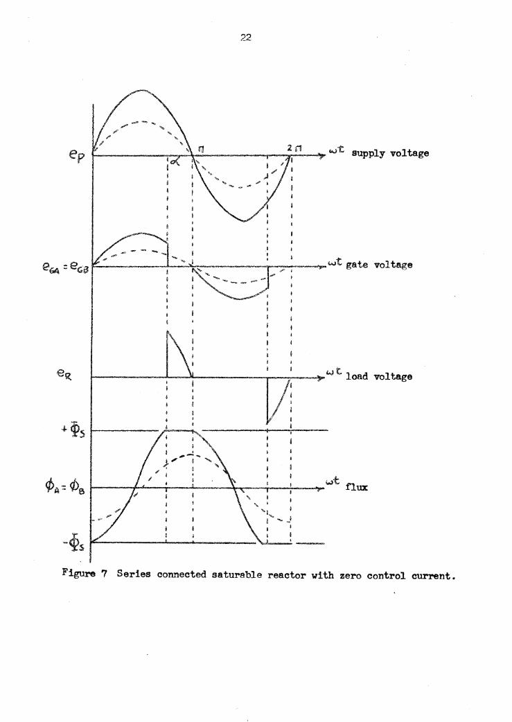
When the control current in the circuit of figu.re 6 is zero the
operation will depend solely upon the magnitude or the applied a.....e
voltage. Should. this voltage be less than the saturation voltage
the reactor cores will offer a high impedance in the gate circuit+
The onl7 current that will exist in the gate circuit will be the
exciting current. Ho"Wever should. the voltage applied be raised to
a value greater than the saturation 'Vloltage the two cores will
saturate and unsatUl"ate during the c70le.
When the smaller value of voltage is applied the dotted wavefonns
in figure 7 depict the circuit conditions. The applied voltage divides
equal.17 between the identical gate vindings. The flux varies in a
sinusoidal manner between the saturation limits. We current except
the exciting eurrent exists in the gate circuit.
With the application or the larger value of supply voltage, it
·will also b9 divided equally across the gate windings until such t::Ime
as the cores saturate. At this point, the firing point, the voltage
will a:ppear across the resi.Stance in the gate circuit and gate or
load current will exist. These eond:l tions are shown in figure '7 as
the solid curves.
22
supply voltage
1--------A---Jll..------------~""' t load voltage Ji I 4 ~5 ..._ ______ .,;.~~--- __________ 1_
Figure 7
e I ' ~, .... --
I
I _,
Series connected saturable reactor with zero control current.
23
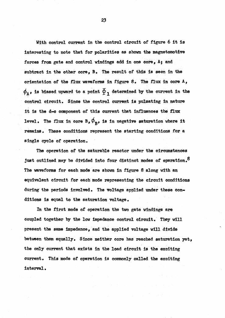
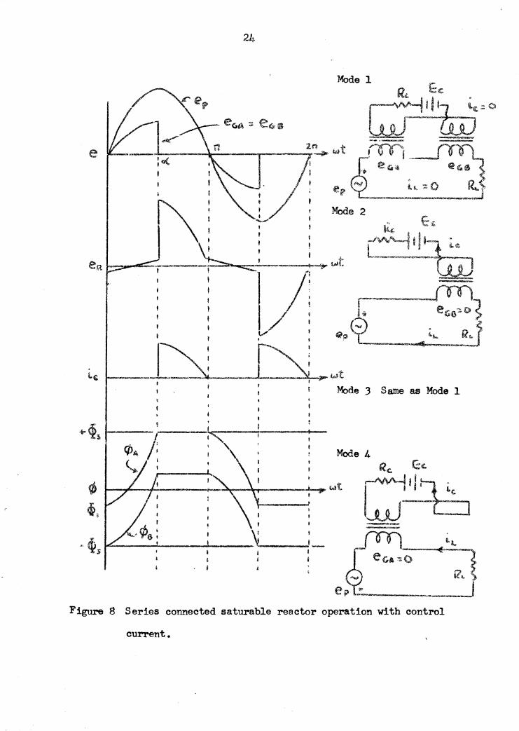
With control cul'1'Snt in the control circuit of figttre 6 it is
interesting to note that for polarities as shown the magnetomo'bive
forces from gate and control windings add in one cc:re, AJ and
subtract in the other core, B. The result of this is seen in the
orientation of the tlux waftforms in figure 8. The flux in core. A,
¢1 , is biased upward ·to a p~int ~ 1 ·determined by the current in the
control circuit. Since the eontrol ourrent is pul•ating in nature
it is the d-e component of this current that :t.nnuences the tlux
level. The nux in core B, </>1 , is in negative saturation where :l.t
remains • These conditions represent the starting conditions for a
sirtgle cycle or operation.
The operation of the satt1rable reactor under the ciroumstanoes
just outlined may be divided into four distinct modes of operation.s
The waveforms for each mode are shown in figure g along with an
equivalent circuit f'or each mode representing the circuit conditions
during· the periods involved. The voltage applied under these con ...
ditions is equal to the saturation voltage.
In the first mode of operation the two gate windings are
coupled together bT the low impedance control circuit.· They will
present the same impedance, and the applied voltage will divide
'between them equall:r. S :lnoe ne! ther core has reached saturation yet•
the only eurrent that e:d.sti!J in the load circuit u the exciting
current. This mode of operation is commonly called the exciting
interval.
24
Mode 3 Same as Mode 1
~~:t I ;; I
q, io
(lf1f) e,L 1- e Ga ~ o .. -- of·.._,:;,,..]· ~ !?~ .
e i? ....._ ______ • . •
N tf>s
Figure 8 Series connected saturable reactor operation with control
current.
As core A saturates the second mode 'begins. When saturated,
¢A will remain constant causing the voltage across gate A,, eGA, to
become zero. At the Sa?l'le time, since the control circuit acts as a
short circuit on the gate winding of B, eGB' the voltage acros.s gate ' '
winding B will go to zero. Since •aB is zero there is no further
increase :bl ¢13 • With both gate voltagel!I equal to zero the en.tire
supply voltage will appear across the load resistance \ and load
current 1t will exist. Since core B is unsaturated its Windings
will act as a transformer dictating that a current in the control
circuit will exist such that
This mode of' operation is commonly called the saturation interval.
With the beginning or the negative halt cycle of the applied
voltage eore A will come out or saturation thus beg:bming the start
of the third mode. Since both cores are now out of saturation, ve17
nearly the same situation exists as it did in the :tiret mode. The
only difference being the opposite polarities. The applied voltage
will be divided equally between the two gate windings • The only
current existing in the load circuit will be the core exciting
current.
Finally core B will be driven into saturation signalling the
· fourth or last mode of operation for the cycle. The entire suppl7
voltage Vill appear across the load resistance indicating the
existence of load current. Since core A is now acting as the current
transformer, and ·since the relationeb!p between gate an4 'Contl"f4
winding is opposite ct tbat tor core I tbe OUJ'Nnt in . the .,cen~l .
· cirtntit vill again appear as, a; posit:lw pd••• Anal.79!8 of the oontrol C\U"Nnt wa'Nt~m·by.the FG'Orl.er·•riea
will indieate that it is :M.de up ot a ·d-e oOlaponent ·and all even.
order lvn.•'JIOniOI.. Thia then is the reason tor callJltc. the. operation
et a eaturable reactor With low centrol c:lrouit tmpedanct natunl
magnetization; or as 11ome authore call it tree even hal"llCtdC
current open.ttos ..
::tt is interening to :note at this point that when tctrehhott•a
voltage law is applied to the gate circuit, and the result integrated
as i11 equatiena 1 eel 2 that the volt-time and flux linkage relatiou
are in complete agreement with these indioated by the wavetcmu.
Lav 9' '9-1 !In!! bN During the interval in which core .A is aatU1"8ted, core B,
while suataildng no tlux change, remains un.satuated. l'l'Oll t!.gure 2
it aq be seen that when the core is unaatur&:ted the onl7 mt 1a that
due to exciting our:renta. · Colnpared with the 118.pitu4ea of load and
control currents tlde may be considered negligible 1n order to .....
tabliah a relationship between lead and control OU1"'.l'ent. During
both saturation intervals the ·current that exists in the lad circuit
lllfl!t; ··• balanced by OU1.'re11t 111 the control eil"•d:t., Thl1 relationship
_,. be abown. u
4
Denoting I as the average value of the rectified load current, L
and t 0 as the average value of the control current, the current
relationship in equation 4 can be put into a more useful form.
Integration of equation 4 will lead to the integrals representing
the average values just defined, 1t and I0• Equation 4 may be re-
vritten as
This equation is commonly referred to as the lav of equal
ampere-turns. Equation 5 is valid under all conditions except in
eases where the saturation intervals overlap, and also where the
gate winding nmf during the exciting interval is not negligible.9
Examination of the waveforms in figure 8 reveals that increases
in control current cannot produce unlimited increases in load
current. The largest value that I may attain occurs when the firing L
angle is zero. Under these conditions there is a maximum rectified
average load current as described in equation 6.
Il.,l'U~Y:. = E'P/'R1.. 6
Where EP is the average value over half a cycle of the applied a-c
voltage and Ry, is the load resistance as designated in figure 6.
When the control current is zero the firing angle is 1T radians,
and the load current is zero. As the control current is increased
the firing angle c:<. , decreases; resulting in an increased. average
load current. The limit occurs when 6( is zero. These relationships
2S
will be discussed in a. later section dealing with the reactor
characteristic curves.
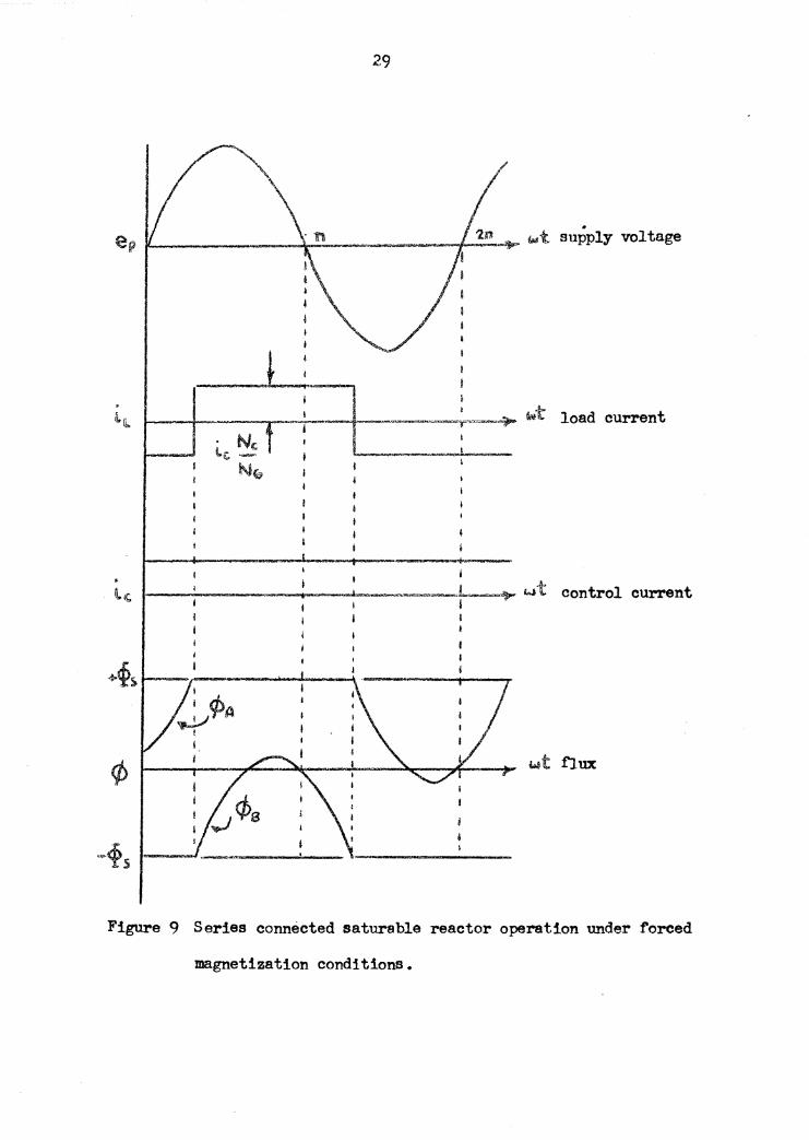
Se.tumble Reactor 2e!ration Under P'o:rced Magnetization
When the control circuit has characteristics such that even
harmonic currents are suppressed in the control circuit the reactor
is said to be operating under conditions of forced magnetization.
This type or operation tends to produce a load current wavef om
vhich is flat-topped. The high impedance control circuit ean be
attained either by inserting a series resistance, or a series
inductance. The series resistance effects the power loss in the
control circuit. The series inductance, on the other hand, does
not appreciably effect the power relation, but instead gives the
control circuit a large time constant.
When the control circuit impedance is high the energy source
in the control circuit may be considered as a constant current
source. The fact that the control current is eonstant dictates an
important factor in this mode of operation. From figure 6 notice
that the net mmf' .for core A may be expressed as 10 10 + iL N0;
while the net mm! for core B may be expressed as ic 10 - 1t. Ne• If
i 0 is to remain constant it can be deduced from the two expressions
for net mmf' that both cores may never be unsaturated together.10
The waveforms of current, voltage, and flux for a saturable
reactor opera.ting under forced magnetization conditions are shown in
figure 9. Drawn for a relatively low value or control cur.rent these
wavetonns shov the flat-topped characteristic of the load cUl'l"ent.
29
wt load current
I 1~~~~~~~~-.---~ ...... --~~--~•1 ______ ....,~ wt control current
I
+cp> ,._ __ , ______ ...__--\ --------....
wt flux
Figure 9 Series connected saturable reactor operation under forced
magnetization conditions.
30
S !nee both corea ..,- not be unsaturated at the same time, owr
a e,.cle of operation firat one and then the other pair of Windings
will act according to the law of equal ampere turns. The net effect
is that the control C'lll"Mnt is reproduced in the load circuit with a
magnitude de.fined by the turn.a ratio, and a direction def'ined by' the
nature ot the windings. Since the two gate windings are wound
oppaei te in sense, with reapeot to the control winding, the eurrent
waveform will have the appearance ot a square wave. The change
from positive to negative values and vice veraa occurs at the points
where both cores are saturated at the same time.
The conditions ot forced magnetization are not cOIDBOn in
practical applications. One of' the popular applications ot thia
mode or operation is in the metering of large direct currents • The
square wave output :ls recttitied, and measured as d-c. The circuit
is said to act as a d...o transformer.
31
IV. TJIE l'WL!Et CONNECTED SATUJU.BLE .REACTOR
In addition to the series saturable reactor connection discussed
in the previous section• a parallel winding arrangement is also in
popUl.ar usage. Fig'lll'e 10 shows the circuit cor.mections f'or sueh a
parallel arrangement. The explanation contained in this seetion
will be based upon eperation Ul'lder natural magnetization conditions.
In this case natural magnetization operation is characterized by a
steady or smooth control current. After examination or the wave-
forms of figure 11 presented in conjunction with the parallel oper-
ation .the reason tor describing the operation as natural magnetisation
will become apparent.
In figure ll the interval 0 to o<'. :f'indtt the entire supply voltage
developed across the gate windings. Accordingly the flux waveforms
will increase • Since the f'lux in core A is biased by the d-c control
current core A will saturate at angle o< • No voltage will then be
sustained over either gate winding since the two gate windings are
in parallel• While not in saturation the flux of core B will be
conste,nt as a result of the zero gate voltage • With the supply
voltage now develope.d across the load resistance the existence or load current is indicated. During the second half cycle of operation
the results will be similar except that core B will now be the one
that is saturated.
During the first saturation interval the path through gate
32
·--------··----· ___ J __ ~-~·---~ El(. Ot
J A
-~·--1
t ~--==--. B
Figure 10 Parallel connected saturable reactor.
. le
33
·-----~wt ' i
I
I 1
I I
R I i
f
gate voltage
t;;t- wt load current
t.. ' I
gate cuttent
' I ! f-...=---.....1..---~--l...----~-..,· -= /t ~ wt gate current : VT
I C I ' I I
I
. ·~ wt control current --~~~--~~~~-~~-~~~~-' I
I
-t~s 1----~- r----....·-__ ....., ___ ...,.., __ _
i
~·<Ps .-.-----~___!..._- L_.____' -
Figure 11 Voltage, current and flux waveforms for a parallel connected
saturable reactor.
.34
winding B vill be a. high impedance path due to the large ref erred
control circuit impede.nee• On the other ·hand the bnpedanoe of path
A will be low• The load current vill be the gate current ot A tor
the first. saturation interval• and. ot B for the se(3ond. . Since there
is no d-c voltage source available in the gate and load circuit the
gate.current of each C0%'9 must hav• a zero avel"tlge ruue •. Hence
the ot:f'set . cunent wavef o!mfJ •
NoM.ce that the tree even harmonic currents which are oharaoter-
isties of natural magnetisation ere fo'tl!ld in the gate ourrent compon-
ents of the load current.
35
V., STEADY STA'.rl SJ.Tt.JBABLE llU.O'fOR CHARAOTERlSTICS ·
Steadt state opei'&tien of a aaturable 1"9aot• !• defined tn tena of three wriablet, The •uppl7 rutage, the load eurrent,
and· the control ouiwre:nt ai:te the tbree ·variable•• The· .clJaraete11!etio
C'llr'8S relating control current and load current with'supplJ'voltage
as a j>al'ameter are oommon:ty oal.184 the control eba.racter:leti•.
Supply voltage and 1-4 cunent With the control current aa a
parameter are related on the 11eltage-cmrreat obare.cterf.st:t.o CU"9•
Oop;tpl Chal'flg:\i!rhti1
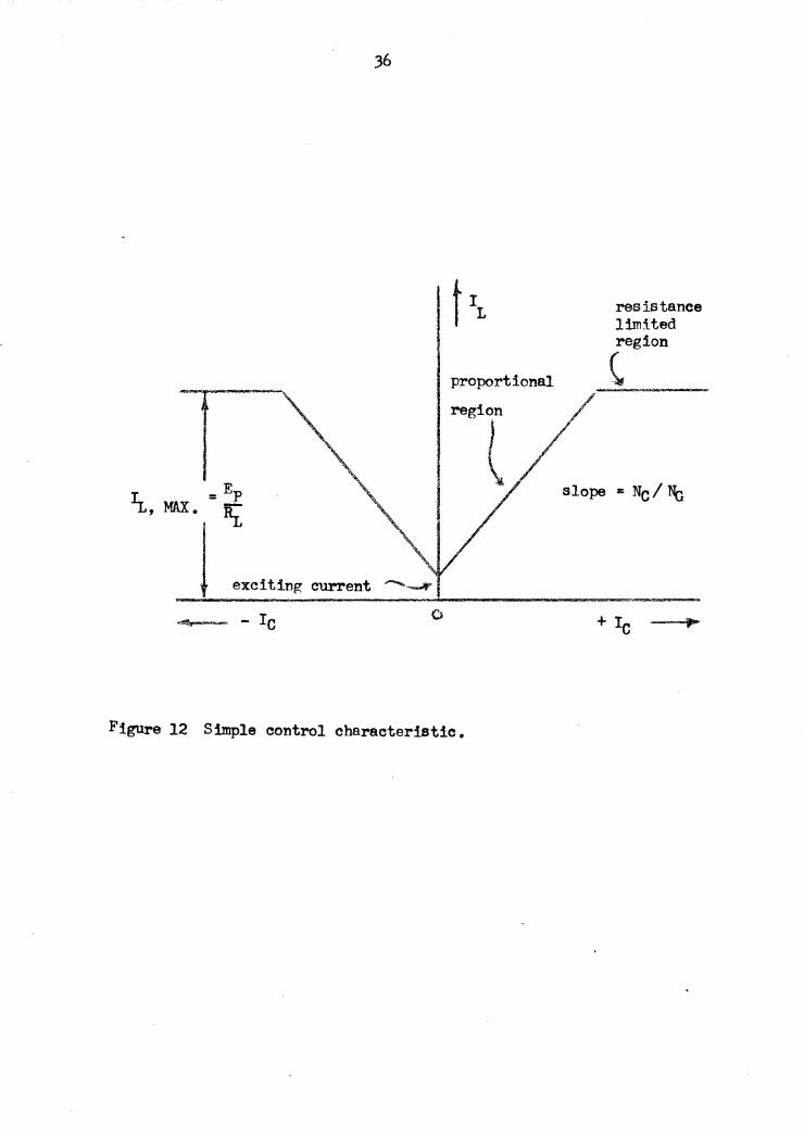
The ample control clsftoter!atie can 'be evaluated trcD a
series sat'm'tlble reaotor comieetton with the saturation voltage
applied. Under thete com!:t!ons the load current will be Rr01 or
equal to the exeitiq current, wbea the control cvnnt ls serch Increues in the contl'Ol euft'ent yield linear increase• hi the
average load cu.nent. From the wavetorna :ln figure 8 tbe increases
in load current are characterized by a decrease in the tiring angle o<:.
The slope of the linear region, 001llllOnl1' called the proportional
region, is deaeribed by the law of equal ampere turns • Continued
increases in the control current will eeaae to yield hel'CN\\lelil in the
load current when the tiring angle nachee zero degrees • This point
waa delilcrlbad earlie:r u the max1'm'am load OUJlll"&nt attailla'bl• • The
only f'aetors exerting a117 1l'J.fluence upon the load ~t at th!a
point are supply voltage and load resistance. Thia ftgion, 1 tor a
proportional region
resistance limited region
(
} \
I/ /"-
slope = Ne I No
0 + Ic
Figure 12 Simple control characteristic.
37
particular applied voltage, is referred to as the resistance limited
region. The simple control characteristic is show in figure 12 •
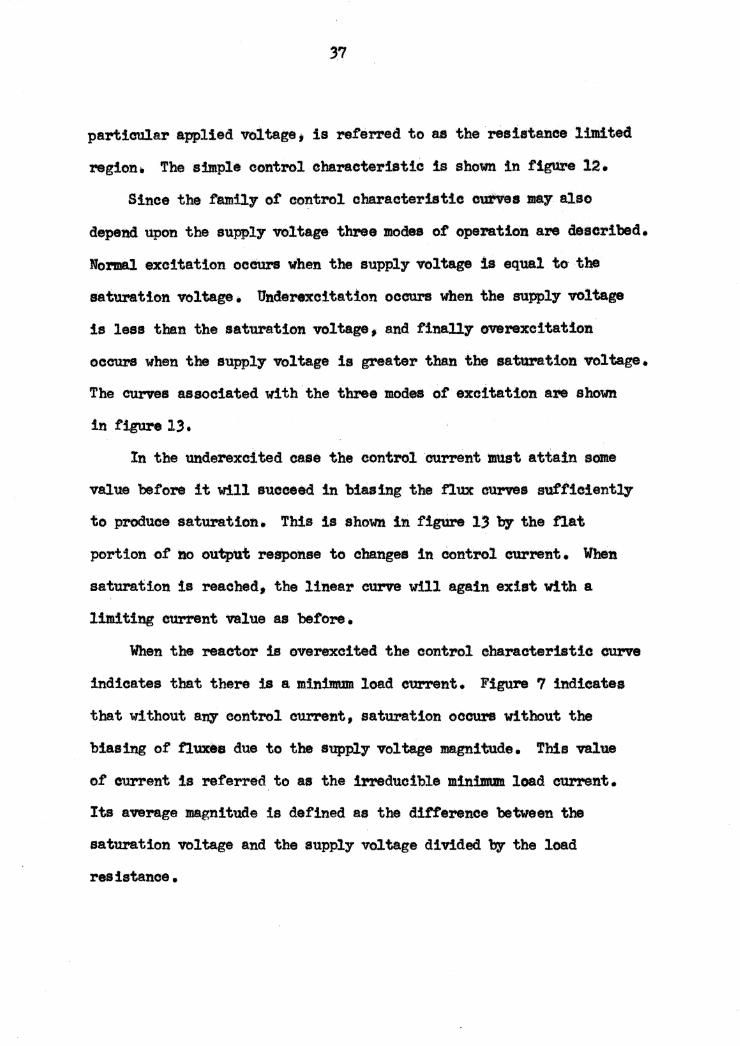
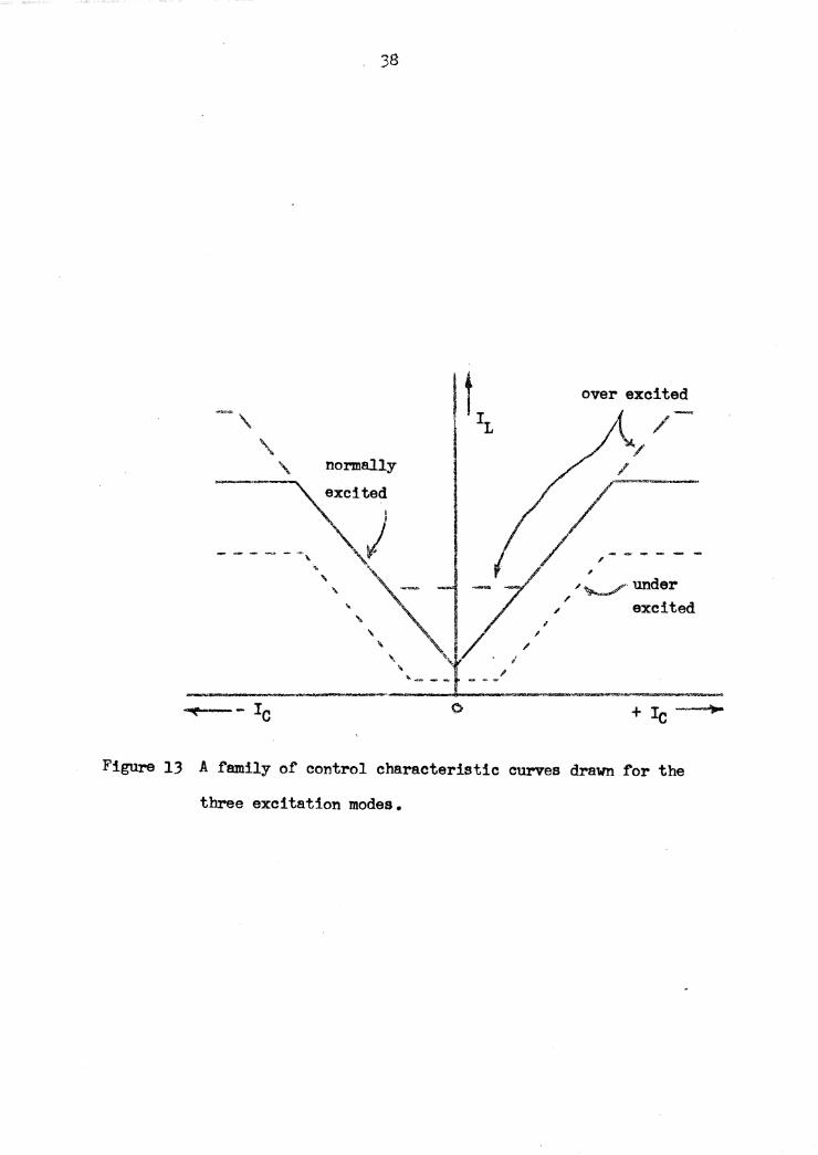
Since the .f'ami.17 or control characteristic curves •1 also
depend upon the supply voltage three modes of opention are described.
Normal excitation occurs vhen the supply voltage is equal to the
saturation voltage. Underexcitation occurs when the supply voltage
is less than the saturation voltage, and finall7 overexcitation
occurs when the suppl7 voltage is greater than the saturation 110ltage.
The curves associated with the three modes of excitation are shown
in figure 13.
In the underexcited case the control current must attain some
value before it w:Ul succeed in biasing the .f'lux curves sufficiently
to produce saturation. This is shown in figure 13 by the flat.
portion of no output response to change• in control current. When
saturation is reached, the linear curve will again exist with a
limiting current value ae before.
When the reactor is overexcited the control eharacterist:!c ourve
indicates that there iS a minimum load e1ll".l"Elnt. Figure 7 indicates
that without anl" control current, satUl'S.tion ocOU1'S without the
biasing of fluxes due to the supp17 voltage magnitude. This value
or O'llr'.'rent is referred to u the irreducible min:i:mum. load eUl'"rent.
Its average lllagnitude is defined as the dii'f'erence between the
saturation voltage and the supply voltage divided by the load
resistance •
38
t L
over excited
normally
.. _ - --~--- Ic + Ic
Figure 13 A family of control characteristic curves drawn for the
three excitation modes.
39
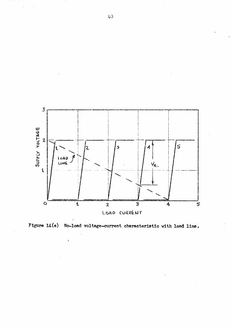
Voltage-Current Characteristic~
The voltage-current charaeteristies tor a saturable reaeto1'
are normally plotted £or a no-load condition. That is to say with
Rx, equal to aero. The eharacteristics for a pa.nioular load resis•
ta.nee can be derived trom this by the application of a load line.
A curve of voltage versus eurrent ie valuable in determining s.
satisfactory load resistance tor the satura.ble reactor to work into.
Figure l4 (a) depicts the no-load voltage-current OU!"ril drawn
to a scale of arbitrary units. For zero control current the onl.7
current in the load circuit Vill be exciting current as indicated
until such time as the saturation voltage is reached. At thie point
the load c'lll"1"Snt increases es · the f'lux is driven. more and more into
saturation.. For other valttes cf control eurrent the curves will be
similar except that the vertical porti.ons will be of s. magnitude
related to the control current by the ratio of t'l'U'DS.
The effect of' the load resistance as expressed by the load line
is a :function of the drop across the load resistance due to the load
current. The supply voltage with a load resistance in the circuit
is the sum of the average no-load supply voltage (gate winding voltage)
and the average load voltage.
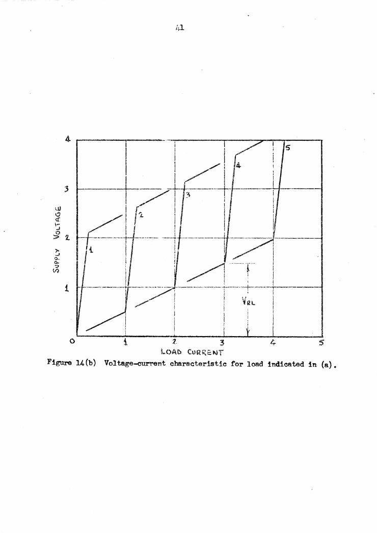
The resulting curve or the characteristic response for a finite
load resistance is drawn in figure 14 (b) • By performing the operation
described in the previous paragraph this construction :ls possible.
40
·'I_ I..--------;; t- ......... __ ™--'~~~
I ; ! ! l I ' ! !
i +
0
Figure 14(e) No-load voltage-current characteristic with load line.
-----...,------- ·~--· -----~---..,..-l"'-.,,------. l s
1, ; ....... 1 .. ' I/ , I~ I
3
\.JJ I!) <X 1-J
~ 2. ,.. ·-' CL c.. -:>
\/)
I ./ ! 3 . ! i / ! I I ! / l I i 1 r i i i i J'l : l !
. -~il ___ __j/----·--------! I f---·---- ! I i I 1
, t I ! . ! ! /1 -----r- I
t ~ i' I i --· ·-·-· --·----rr----- ------ -- ·----..... -·---- ~-- -· -··--1-··· -----+------
~ . ; ; i
/ i \/Ill ! ' I I . i ! : l
i ! i I
\ I 0 i 3
lOA.tt CORi\f;t.J'f Figure 14(b) Voltage-current characteristic for load indicated in (a).
42
The selection of the proper load resistance in a saturable
reactor circuit is found by referring to the family of voltage-
eurrent curves • The load line should be laid out so that changes
in supply voltage for a specific value of control current do not
cause an appreciable change in load current. The load line must
also be laid out so that it covers the range of control currents to
be used.
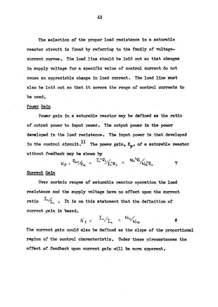
Power Gain ---Power gain in a sa.turable reactor may be defined as the ratio
of output power to input power. The output power is the power
developed in the load resistance. The input power is that developed
in the control circuit.11 The power gain, 1), 1 of a saturable reactor
wi.thout feedback may be shown by
7
Current Gain ----Over certain ranges of saturable reactor operation the load
resistance and the supply voltage have no effect upon the current
ratio L.;!c.. • It is on this statement that the de:finition of
current gain is based.
8
The current gain could also be defined as the slope of the proportional
region of the control characteristic. Under these circumstances the
effect of feedback upon current gain will be more a:pparent.
43
VI. FEEDBACK IN MAGNETIC AMPLIFIERS
The saturable reactor as such, has a relatively low power
gain limited by its design. Saturable reactors find many applications
in this form, but additional applications would be available if the
gain could be increased. The increase in gain may be accomplished
through the use of feedback. By feedback is meant the utilization
of a portion of the output quantity in such a manner so as to act
for or against the input quantity. Naturally the increase in power
gain comes about when the feedback assists the input. Feedback of
this t:ype is often called positive or regenerative feedback. Since
feedback is a function of the output, namely load current, it may
be achieved by several methods two of which will be described here;
magnetic feedback and self-saturation.
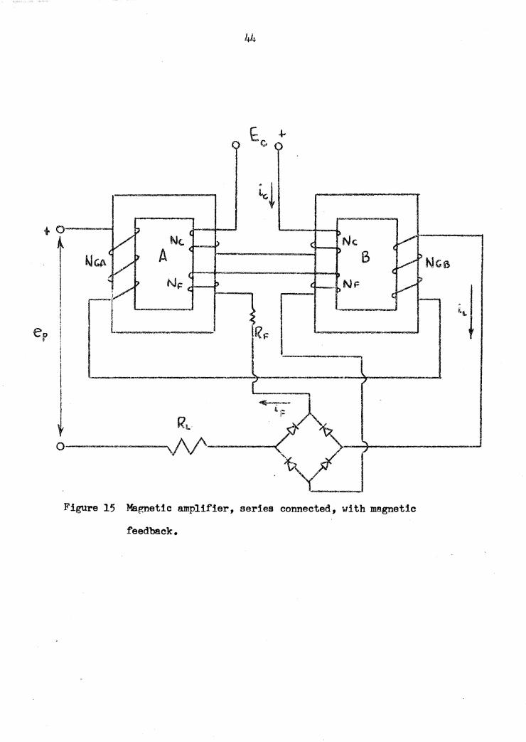
Magnetic Feedback
Magnetic feedback is accomplished by using an additional set
of vindings on the two reactor cores • These windings are fed from
the load circuit by a. rectified form of the load current. Figure
15 show a typical magnetic feedback arrangement. The feedback wind-
ings :in figure 15 are oon.nected :in such a :manner that their mmf' will
aid the control mmt. The current gain of' a reactor connected in this ma.nner will be
different from the current gain already mentioned by a factor
involving the number of feedback ~rindings N, • The nunf equs.tion
+o-~-
1
I er I
i I l I ~ o---- - -~·-------c
Figure 15 Mar-netic amplifier, series connected, with magnetic
feedback.
45
around one of the cores in figure 15 will be
lc.~c.. ~ IF ~i: -:::: I .. l\\<:,
where IF is the average of the current in the feedback winding.
Solving equation 9 f'or the current gain yields
9
KI :: 1.,/rc. ::. Mc~c. [ '/1 - Ns:/I'!" J 10
From the defin:t tion of load current and feed.back current I1 * IL t
leaving the ratio of N~u in equation 10. The ratio ot N~&
is called the feedback factor.. Notice that when NF = 0 as is the
case without ma.gnetic feedback that the expression reduces to
equation S.
The addition of the feed~ck winding will alter the shape of
the control characteristic by an a.mount dictated by the feedback
current and feedback winding turns. This can best be shown graph-
ically by '.Nldrawing the control characteristic in terms of control
and load ampere-turns • This is done in figure 16. S inoe the feed ..
back effect is additive to the control effect for the winding arrange-
ment .in figure 15, it may be plotted versus load current ampere-turns
in the same manner as control ampere-turns • This curve of feedback
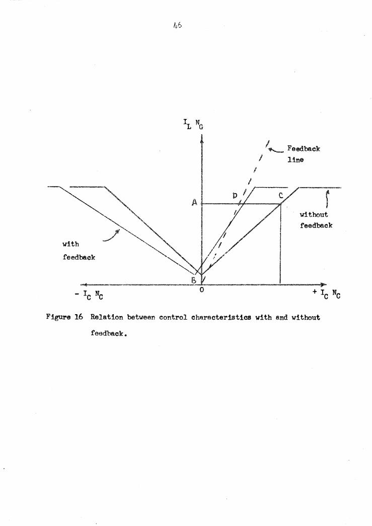
ampere-turns ii oalled the feedback line and is shown in figure 16.
The control oharacteristic for an amplifier with feedback can
be constructed using the feedback line and an ordinary control
characteristic. In figure 16 it may be. seen that for a ,load current
mmf of AB ampere-turns it is necessary to have a control mmf" of CA
ampere-turns without feedback. With feedback, though, the :feedback
with feedback
h,.6
I I
I...__ Feedback I line
r without feedback
Figure 16 Relation between control characteristics with and without
feedback.
47
current would produce AD ampere..;..turns at this same value of load
current. This indicates that it is only necessary for the control
winding to produce the difference• or DC ampe:re-t'l13:'h8. Plotting
DC control mmf and AB load mmf" a point on the new chara.cteristic is
obtained. Other points may be gotten the same vay.
When the control current is increased in a positive direction
the flux produced by the control windings aids that produced by the
feedback windings • The core fluxes are then 'biased further a.part
resulting in a small.er firing angle. As a result o.f this the load
current increases more per unit change in control current. This
situation will continue until the firing angle reaches zero degrees.
At this time the load ciirrent will be limited by load resistance as
previously described.
If the control current is increased in the negativedirection
the fluxes produced by the control and feedback windings oppose.
The firing angle will get larger for a period causing t'Urther
reduction in load current. At the point where the control mmf' and
feedback mmf are equal and opposite the load current 'Will be a
minimum. Further increases in the control current produces a flux
that overcomes the nux produced by the feedback winding. The
result will again be a decrease in the firing angle and therefore
an increase in the load current. One could say that the magnetic
amplifier with feedback is polarized,. That is to say that the
reaction to positive and negative values of control current is
d if'f erent •
48
The effect of feedback on the power gain can be found from it3
de.fi.ni tion and from the current gain expression of equation 10,
k'p -== K':r -z 1<1../R( -= ~c~Gt Rt.if2c [Yi - ~F/Ncr l 'Z.. 11
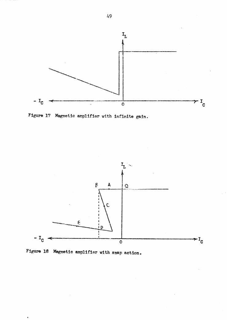
Control Cha;racterist!g !2£ Feedback Factors !2l, Unit;z 2t Above
As the feedback factor is increased to unity and above the mode
or operation is called infinite gain and snap action respectively.
This tyPe of operation is unstable due to the two operating points
that exist for a s1.ngle value or control current. Actually, in ·t.he
interest of good stability, the feedback factor must be kept below
o.s;. A me.gnetic amplifier with infinite gain exist.a when tbs feed-
back factor is equal to uni.ty. This means that. the slope ot the
feedback line will be parallel and to the right of the proportional
region of the control ebaraoteriatie without feedback. The control
cha:raateristic for this situation is shown in figure 17.
A magnetic amplifier with snap action operates in an interesting
manner. Referring to figure 18 the magnetic amplifier is opera.ting
at its quiescent point Q. A negative increase in the control volt-
age will move the operating point along the characteristic toward
point A and finally to point B. If the control voltage is increased
a slight bit more a reduction in core flux results along with a
reduction in load current. This puts the operating point at point
C where the applied control mmf is larger than that required for
operation. The surplus control voltage is developed across the
control winding further reducing the core flux and load current
49
Figure 17 Magnetic amplifier with infinite gain.
A a
-~
Figure 18 Magnetic amplifier with snap action.
50
until point D iB reached. From this point on the operation is
stable.
When the feedback factor is raised to a point greater than
unity the result :ta a large change in load current. for am.innte
change· in control current. In the case of' 1'el.a.y operation the
change in relay current tro:in a s.il value below the relay pickup
current to a large value above the pickup value produces a rapid
sure contact action.
It should be emphasized that :lt takes a certain amount of time
. for the load current to ·snap from B to D in figure lS. The time
during which ~hese changes occur is short, but it is finite •.
Oscillograms taken during the snap period prove this point and also
prove that the control and load currents are actually mo'Ving along
the a-shaped characteristic.12
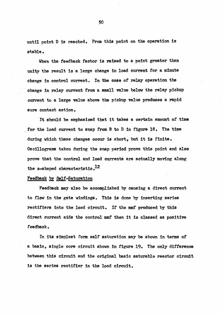
Feedback .!?% Self .Saturation
Feedback may also be accomplished by causing a direct current
to flow in the gate winding& • This is done by inserting series
rectifiers into the load circuit. It the mmf produced by this
direct current aids the control mmr then it is classed as positive
f'eedback.
In its simplest form self saturation may be shown in terms of
a basic, single core circuit show in figure 19. The only difference
between this circuit and the origil'lal basic sat'!ll"ab1e reactor circuit
is the series rectifier in the load circuit.
51
Figure 19 Basic single core self-saturating magnetic amplifier.
52
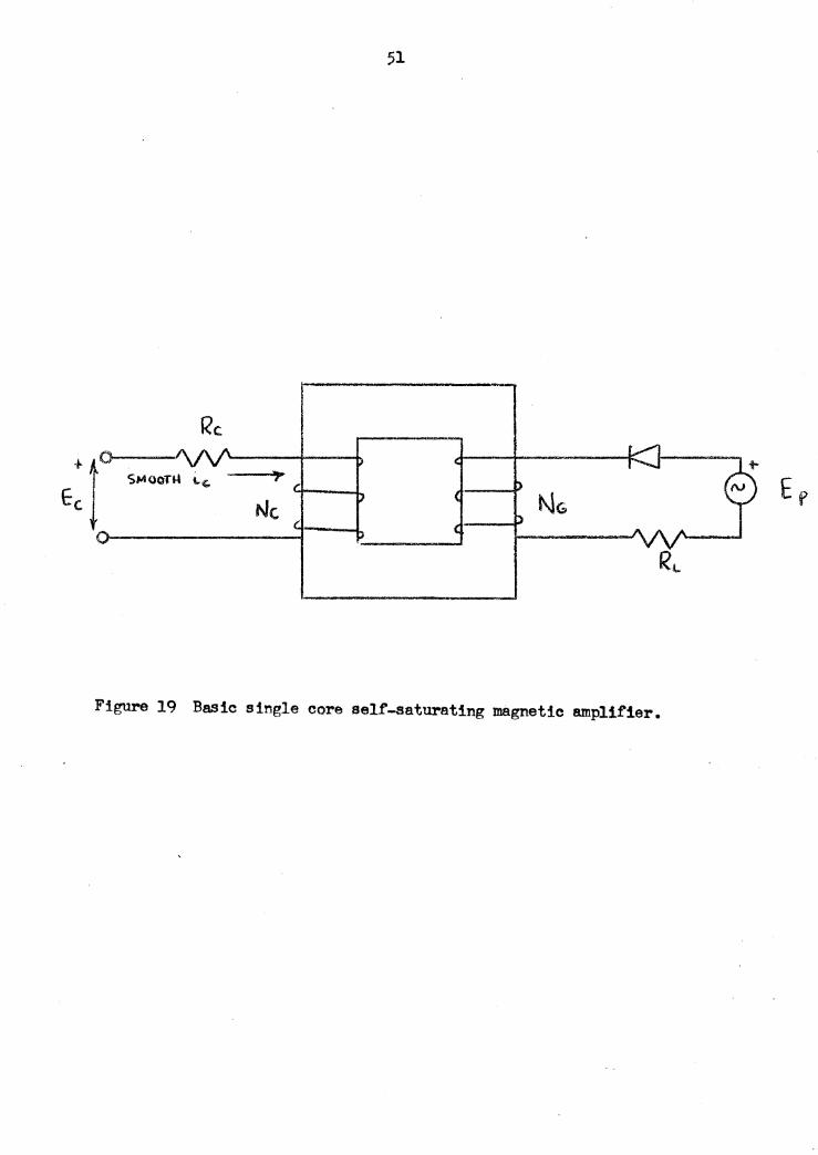
The steady state operation of' the self-saturating device is
described in the waveforms of figure 20. These wa.Yeforms are
based on the assumption that the control current is constant.
Between wt = O and o( the applied voltage :ls developed across the
gate winding due to its high reacts.nee. The nux variation during
this interval is determined by the gate tdnding 'V'Ol tage • The
current that exists in the load circuit will be the core exciting
current.
At wt =o<: the flux has been driven into saturation and the
entire supply voltage will developed across the load resistance.
This statement is true if the gate winding resistance and rectifier
forward resistance is negligible. The load current has the form
shown in figure 20 (c). At wt = 1T the core becomes unsaturated
reverting the gate winding back to its high in.ductance state • The
load current continues to flow trailing off at wt • o<.. + .Tr. During
this interval the rectifier continues to conduct the trailing cu.:rrent
and the voltage across the rectifier will be negligible. The gate
winding voltage exists so that the flux may reset itself to its 13 original value (i1 • At wt = (o( +Tr) the rectifier assumes an
infinite resistance and all of the supply voltage is developed
across it.
2.!J,!-S eturation .!!:!. ~ ~ Magnetic Am.Flif:ters
Possibly the main point of self-saturation is the unidirectional
current which exists in the gate Winding. The direct current
53
r- 2. li'1l :t (a) e e:, -··-·-..,,.. \lJ « I , . , 1 «: -1t flJ !
I I . J l
I I I I N ,'. I "'
l I I I I ;
=--· '--- : ! t (b) lb. >--::_ ~! .. ----:-.--~~ w i i
I v ~E.<.T. I··-"" !_Twt (c)
+~:$ •-----,-----i-..-----+v~'---~
gate and supply voltage
load current
rectifier voltage
I l 1----+-........ ___ --t_, ___ _...,___;, ___ ._Jp wt (d) nux
I
~ ~5 t----__._---~·-'----------'---
1 Figure 20 Wevefonns depicting the operation of a single core self-
saturating device.
54
component of this pulsating.eurrent acts to. produce the feedbaek
ettect •. Figure 21 •hows: the circuit anangemen:t or a magnet1e
ampli:fier employing.,.elt....saturation.
Consider the supply voltage polarity shown h figure 21-.
Current would erlst 1n the gate winding ot eoreB because ot the
arrangement of rectifier B. Durinc··the subsequent·.halt· OJCle
rectifier A will eonduct1 and a pulse of .current will exut :t.n
gate winding A •. In ea.eh gate winding there appears a unidireotton.i
pulse of current. This situation vill yield the necesaa1"1 d-c
component. required for se1t...aaturation. The result at the load is
an alte:mating.current fed first by one oore and then the othe!"•
The magnitude of the lead current is dependent upon the
magnitude and polari t:r or the control voltage • With a d""° pol&.!"i ty
such that the flux :p!'odueed by the control voltage aids tbat pro...
dttoed b:r the gate winding the result will be a higher magrd.tW!e of
load eurrent • Inoi-eues h the control current will drive the
firing angle to sero and the load cunent 'Will 'be lbrl.W ·0:r the
circuit resistance.
It the polarity :ts reversed in the eontrol of.remit the tluea
produced by the two windingl will be in opposition •. The result
will be a lowering of the load current level. This. will continue
until the. nuxea are equal and opposite. Thi• eanoelling ot f'luxes is represented by the minimum current point. Further
increases in control current will produce an over-riding f'lux whieh
55
A
·------~------'
.. ,.,..........., ·-----1----~~---·-·
€<tCT1!r!fR E>
Figure 21 Magnetic amplifier with self-saturation.

56
will result in a slow increase in load current. From this description
one can see that the control current versus load current cbaracter1stio
curve exhibits the same qualities as in the case of magnetic feedback.
57
VII. BIBLIOGRAPHY /
Literature Ctted
1. "Proposed Standard Terms and Definitions for Magnetic
Amplifiers," AIEE Committee Report, !m! Transactions, 1958,
Vol. 77, Part I,. p. 429.
2. "Proposed Standard Terms and Definitions for M!gnetic
Amplifiers 1 tt AIEE Committee Report, ~ Transactions, 1958,
Vol. 77, Part I, P• 429.
3. Platt, s., Magnetic giplifiers, Theory~ Application,
Prentice-Hall, Inc., Englewood Cliffs, New Jersey, 1958,
P• 6.
4. Storm, R. F ., Magnetic Amplifiers, John Wiley and Sons, Inc.,
New York; 1955 1 p • .3S.3.
5. Platt, S ., Magnetic Amplifiers, Theorz and P:gglioation,
Prentice-Hall, Inc., Englewood Cliffs, New Jersey, 1958, p. 2.
6. Galbraith, R. A..,. and Spence, D. W., Fundamentals .2! Electrical
Engineering, The Ronald Press Company, New York, 19551 P• 2U.
7. Milnes, A. G., Transduetors ~ !fagnetie_ Amplt.fiers, MacMillan
and Company, Ltd., London, 1957, p. 10.
8 • Johnson, W. 0., "The Magnetic Amplifier," Electrict::tf !ngin.eering,
195.3, Vol. 72 1 No. 7, P• 5S5.
9. Storm, R. F., M!gnetic A!Plifiers, John Wile;r and Sons, Inc. 1
New York, 1955, p. 79.
10. Frost-Smith, E. H., !h! Theorz !mt Design g£ Mynetic
Amnlifiers, John Wiley and Sons, Inc., New York, 1958, P• 69.
ll. Platt, S ., Magnetic M!?lifiers, Tbeo!7 and Applieation;
Prentice-Hall, Inc., Englewood Cliffs, New Jersey, 1958,
pp• 119-120 •
12. Storm, H. F ., Magnetic Amplifiers, John Wiley and Sons, Inc.
New York, 1955, P• 201.
l~h Finzi, L.A., and Pittman, G. F., Jr., "Methods of Magnetic
Amplifier .Analysis," Electrical Engineering, 195.3, Vol. 72,
No • g' p. 691.
59
Literature Examined
A ttura, G. M., Mlgnetie Amplifier Engineering, McGraw-Hill Book
Company, Inc~, New York, 1959.
Boyajian, A., "Theory of D-C Excited Iron Core Reactors and
Regulators," Am Transactions, 1924, Vol. 43, pp. 919-936. -Coal es, J. F., "Magnetic Amplifiers," ,!!! Proceedings, 19541
Vol. 101, Part II, PP• 83 ... 99.
Crow, L. R., Saturating Core Devices, The Scientific Book
Publishing Co., Vincennes , Indiana, 194 9.
Dornhoefer, w. J ., "Self...Saturation in Magnetic Amplifiers•"
!IEE Transactions, 1949, Vol. 68, Part II, PP• 635-950.
Ettinger, G. M., Magnetic Amplifiers, Methuen, Iondon, 195.3.
Feinberg, R., ttA Review of Traneductor Principles and .Applications,"
Proceeding IEE, 1950, Vol. CJ"!, Pa.rt II, PP• 628-644
Finzi, L. A., "Introducing Young Engineers to the Apprec:i.a.tion of
Magnetic Amplifier Problems," Am Transactions, 1958, Vol. 77,
Pa.rt I, pp. 119-126.
Fitzgerald, A. s., •Feedback in Magrietic Amplifiers," Journal ,2!
~Franklin Institute, 1949, Vol. 247, PP• 223-2/i).
Frost-Smith, E. H., "The Theory of Magnetic Amplifiers a.nd some
Recent Developments," Journal !?! Scientific Instruments, Aug. 1948,
Vol. 25, pp. 268-272.
Gale, H. M. • and Atkinson, P. D • , "A Theoretical and Experimental
Study of the Series-Connected Magnetic Amplifier," P;i;yceedinge IEE,
1949, Vol. 96, Part I, pp. 99-124.
60
Geyger, W. A., Magnetie...Amplifier Circuits, Second Edition, McGraw-
Hill Book Company, Inc., New York, 1957.
Johnson, w. c., and Latson, F. w., "An Analysis of Transients and
Feedback in Magnet:1e Amplifiers," AIEE Transaction@, 1950,
Vol. 69, Part I, pp. 604-612.
tam, A. U., "Some Fundamentals and Theory of the Transductor or
Magnetic Amplifier," !.m Transactions, 1947, Vol. 66,
PP• 1078-1085.
Logan, F. G • , "Saturable Reactors and Magnetic Amplifiers , "
Electronics, October 1948, Vol. 21, Part III, pf>. 104-109.
M:ilee, J. G., "Bibliography' of Magnetic Amplifier Devices and the
Saturable Reactor Art," m!, Transactions, 1951, Vol. 70,
Part II, PP• 2104-21.23.
Milnes, A. G., "A New Theory or the Magnetic Amplifier," :Proceed!.ng!
_m, 1950, Vol. '17, Part II, pp. 460""'4S3.
Milnes, A. G., "Magnetic Amplifiers:, tt ProceEldingl!l l!mi 194 9, Vol. 96,
Part I, PP. 89-98.
Ramey, R. A., "On the Control of Magnetic Amplif'iers, 1t m!, Trans-
actions, 1951, Vol. 70, Part II, pp. 2124 .. 212s.
Ramey, R. A., "On the Mechanics of Magnetic-Amplifier Operation,"
!m Transactions, 1951, Vol. 70, Part II; pP. 1214-122.3.
Reyner, J. H., The t;tasnetic A!plif'ier, Stuart and Richards, London,
1950.
61
Storm, H. F., "Some Fundamentals o:f' D-0 Controlled Reactors with
Resistive Load," !m. Transactions, 1949, Vol, 68, PP• 1ss~194.
VerPlanck, D. W., Finzi, t. A., Beaumariage, D. C.,"Analytical
Determination of Characteristics of Magnetic .Amplifiers vith
Feedbaek," !!!! Transactions , 194 9, Vol • 6S, Part I, pp • ;65-570.
VerPlanck I D • W. , Fishman, M•, Beaumariage, D. C •, ttAn Analysis of
Magnetic Amplifiers with Feedback," .m! Proceeding, 1949, Vol. 37,
Part II, pp. 862-866.
Oomittee Report, "Magnetic Amplifier Bibliography 1951-19561 "
!l!! Transactions 1 19581 Vol. 77, Part I 1 pp. 613~27 •
62
Vlll. AOKNOW'.LEDGEMENl'S
The author wishes to express his appreciation to
, his thesis advisor, and to
·, Head of the Electrical Engineering
Department tor the interest they have shown, and the help and
cooperation they gave him.
A word of appreciation must certainly go to t,he students in
the Electrical Engineering Class of 1959 for their helpful
criticisms of the material when it ws used as a class outline in
a Magnetic amplifier class taught by the author.
In addition the author would like to express his gratitude
to who typed the manuscript, and to his wife
for her patience and encouragement during the period of
study.

The vita has been removed from the scanned document
AN INTRODUCTION TO THE STUDY OF
MAGNETIC AMPLIFIEBS
John P. Gordon
Virginia Polytechnic Institute
Department of Electrical Engineering
MASTER OF SCIEJK:E THf!SlS
June, 1959
A!BTRACT
The magnetic amplifier is a device employing saturable
reactors as :its basic element. The theor.r or magnetic amplifiers
is developed from the standpoint of rectangular eysteresis loops
that are simplified in such a manner as to eliminate the problems
of nonlinearity.
The saturable reactor may be connected in either sePies or
parallel combinations and their operation analyzed on the basis of
voltage, current, and nux waveforms.
The cha.racteristics or the se.tura.ble reactor circuits may be
enhanced by the addition of feedback. Feedback is accomplished
either by ma,gnetio means using additional windings, or by self-
saturation in which rectifiers are used to secure feedback. The result is a device in which a small amount of power can effectively-
be used to control larger a.mounts of power.