magnetic circuit protectors - airpax hydraulic magnetic ... · introduction. the airpax™ ap...
TRANSCRIPT
AP/UP, AP/MIL SeriesMagnetic Circuit Protectors
• 71
• 72
• 75
• 76
• 77
• 78
• 79
Introduction
Poles
Configurations
Operating Characteristics
Delay Curves
Specifications
Decision Tables
INTRODUCTION
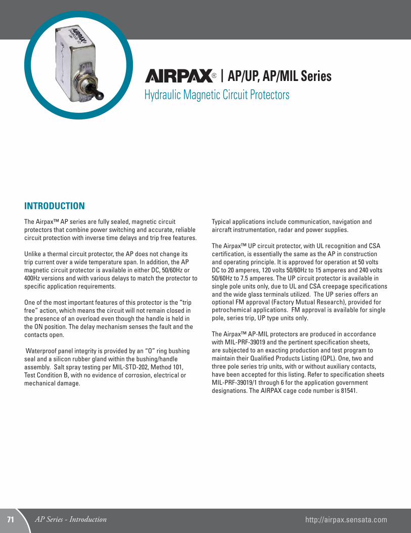
The Airpax™ AP series are fully sealed, magnetic circuit protectors that combine power switching and accurate, reliable circuit protection with inverse time delays and trip free features.
Unlike a thermal circuit protector, the AP does not change its trip current over a wide temperature span. In addition, the AP magnetic circuit protector is available in either DC, 50/60Hz or 400Hz versions and with various delays to match the protector to specific application requirements. One of the most important features of this protector is the “trip free” action, which means the circuit will not remain closed in the presence of an overload even though the handle is held in the ON position. The delay mechanism senses the fault and the contacts open.
Waterproof panel integrity is provided by an “O” ring bushing seal and a silicon rubber gland within the bushing/handle assembly. Salt spray testing per MIL-STD-202, Method 101, Test Condition B, with no evidence of corrosion, electrical or mechanical damage.
Typical applications include communication, navigation and aircraft instrumentation, radar and power supplies.
The Airpax™ UP circuit protector, with UL recognition and CSA certification, is essentially the same as the AP in construction and operating principle. It is approved for operation at 50 volts DC to 20 amperes, 120 volts 50/60Hz to 15 amperes and 240 volts 50/60Hz to 7.5 amperes. The UP circuit protector is available in single pole units only, due to UL and CSA creepage specifications and the wide glass terminals utilized. The UP series offers an optional FM approval (Factory Mutual Research), provided for petrochemical applications. FM approval is available for single pole, series trip, UP type units only.
The Airpax™ AP-MIL protectors are produced in accordance with MIL-PRF-39019 and the pertinent specification sheets, are subjected to an exacting production and test program to maintain their Qualified Products Listing (QPL). One, two and three pole series trip units, with or without auxiliary contacts, have been accepted for this listing. Refer to specification sheets MIL-PRF-39019/1 through 6 for the application government designations. The AIRPAX cage code number is 81541.
AP/UP, AP/MIL SeriesHydraulic Magnetic Circuit Protectors
AP Series - Introduction http://airpax.sensata.com71
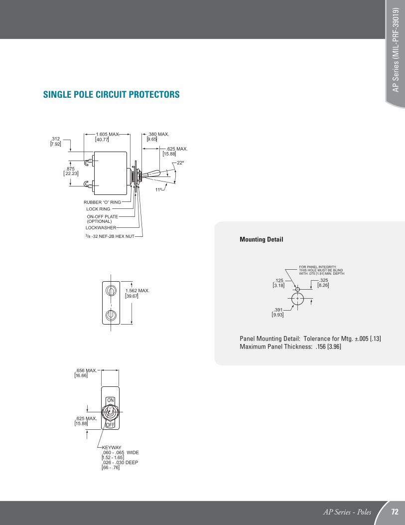
1.562 MAX.[39.67]
22º
11º
.87522.23] [
RUBBER “O” RINGLOCK RING
ON-OFF PLATE(OPTIONAL)
LOCKWASHER3/8 -32 NEF-2B HEX NUT
[ ] .3127.92
1.605 MAX. 40.77[ ]
[ ]
[ ] .380 MAX.9.65
.625 MAX.15.88
[ ]
[ ]
.656 MAX.16.66
OFF
ON
.625 MAX.15.88
[ ] [ ]
KEYWAY.060 - .065 WIDE1.52 - 1.65.026 - .030 DEEP.66 - .76
SINGLE POLE CIRCUIT PROTECTORS
AP Series - Poles 72
AP S
erie
s (M
IL-P
RF-3
9019
)
.1253.18
.3258.26
.3919.93
FOR PANEL INTEGRITY,THIS HOLE MUST BE BLINDWITH .075 [1.91] MIN. DEPTH
[ [
[
[
[
[Mounting Detail
Panel Mounting Detail: Tolerance for Mtg. ±.005 [.13]Maximum Panel Thickness: .156 [3.96]
MULTI-POLE CIRCUIT PROTECTORS
AP Multi-Pole CombinationsCircuit demands and design ingenuity suggest a limitless number of special combinations, ranging from a two pole unit with one series breaker and a simple ON·OFF switch, to a more complex three pole unit having one series, one shunt and one relay configuration with auxiliary indicator circuit contacts. Please contact Airpax for specific part number.
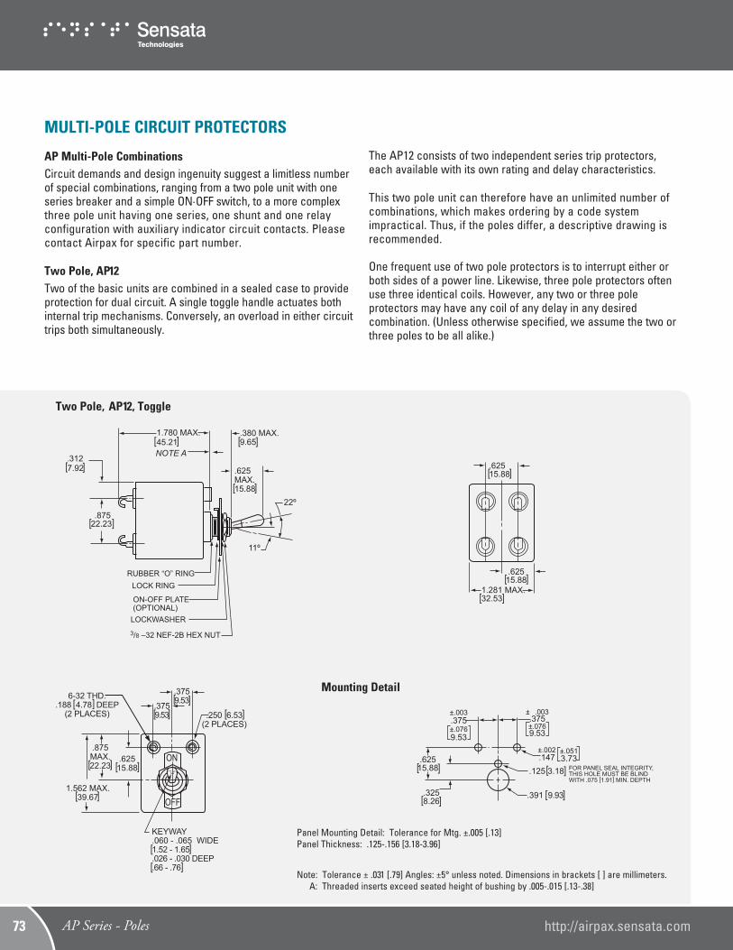
Two Pole, AP12Two of the basic units are combined in a sealed case to provide protection for dual circuit. A single toggle handle actuates both internal trip mechanisms. Conversely, an overload in either circuit trips both simultaneously.
The AP12 consists of two independent series trip protectors, each available with its own rating and delay characteristics.
This two pole unit can therefore have an unlimited number of combinations, which makes ordering by a code system impractical. Thus, if the poles differ, a descriptive drawing is recommended. One frequent use of two pole protectors is to interrupt either or both sides of a power line. Likewise, three pole protectors often use three identical coils. However, any two or three pole protectors may have any coil of any delay in any desired combination. (Unless otherwise specified, we assume the two or three poles to be all alike.)
Note: Tolerance ± .031 [.79] Angles: ±5° unless noted. Dimensions in brackets [ ] are millimeters. A: Threaded inserts exceed seated height of bushing by .005-.015 [.13-.38]
22º
11º
.87522.23][
RUBBER “O” RINGLOCK RING
ON-OFF PLATE(OPTIONAL)
LOCKWASHER3/8 –32 NEF-2B HEX NUT
[ ] .3127.92
1.780 MAX.45.21[ ]
[ ]
[ ] .380 MAX.9.65
.625 MAX.15.88
NOTE A
[ ]
[ ]
OFF
ON.62515.88
[ ] [ ]
KEYWAY.060 - .065 WIDE1.52 - 1.65.026 - .030 DEEP.66 - .76
.875MAX.22.23
1.562 MAX.39.67
[ ]
[ ]
.3759.53
.3759.53
[ ] [ [
.250 6.53(2 PLACES)
[ [
6-32 THD..188 4.78 DEEP
(2 PLACES)
FOR PANEL SEAL INTEGRITY,THIS HOLE MUST BE BLINDWITH .075 [1.91] MIN. DEPTH
[ [
[
± .003.375±.0769.53
±.002.147
.125 3.18
.391 9.93
[
±.0513.73
[
.62515.88
±.003.375±.0769.53
[
.3258.26[ [
Two Pole, AP12, Toggle
Mounting Detail
Panel Mounting Detail: Tolerance for Mtg. ±.005 [.13]Panel Thickness: .125-.156 [3.18-3.96]
[ ]
.62515.88
1.281 MAX.32.53 [ ]
[ ]
.62515.88
AP Series - Poles http://airpax.sensata.com73
22º
11º
.87522.23] [
RUBBER “O” RINGLOCK RING
ON-OFF PLATE(OPTIONAL)
LOCKWASHER3/8 –32 NEF-2B HEX NUT
[ ] .3127.92
1.780 MAX.45.21[ ]
[ ]
[ ] .380 MAX.9.65
.625 MAX.15.88
NOTE A
FOR PANEL SEAL INTEGRITY,THIS HOLE MUST BE BLINDWITH .075 [1.91] MIN. DEPTH
[ [
[
± .003.687±.07617.45
±.002.147
.125 3.18
.391 9.93
[
±.0513.73
[
.62515.88
±.003.687±.07617.45
[
.3258.26[ [
[ ]
1.937 MAX.49.20[ ]
[ ]
.62515.88
.93723.80
[ ] .62515.88
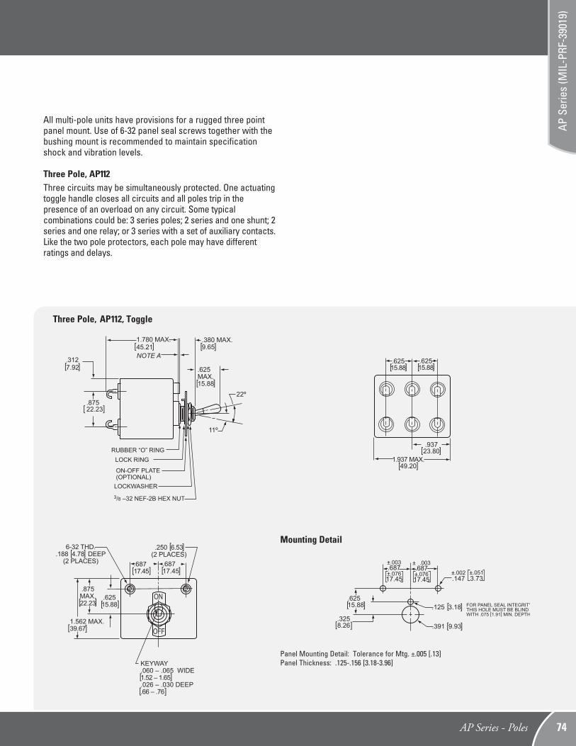
Three Pole, AP112, Toggle
Note: Tolerance ± .031 [.79] Angles: ±5° unless noted. Dimensions in brackets [ ] are millimeters. A: Threaded inserts exceed seated height of bushing by .005-.015 [.13-.38]
[ ]
[ ]
[ ]
OFF
ON.62515.88
[ ] KEYWAY.060 – .065 WIDE1.52 – 1.65.026 – .030 DEEP.66 – .76
.875MAX.22.23
1.562 MAX.39.67
[ ]
[ ]
[ ]
.250 6.53(2 PLACES)
[6-32 THD..188 4.78 DEEP
(2 PLACES) .68717.45
.68717.45
[
[ [
All multi-pole units have provisions for a rugged three point panel mount. Use of 6-32 panel seal screws together with the bushing mount is recommended to maintain specification shock and vibration levels.
Three Pole, AP112Three circuits may be simultaneously protected. One actuating toggle handle closes all circuits and all poles trip in the presence of an overload on any circuit. Some typical combinations could be: 3 series poles; 2 series and one shunt; 2 series and one relay; or 3 series with a set of auxiliary contacts. Like the two pole protectors, each pole may have different ratings and delays.
Mounting Detail
Panel Mounting Detail: Tolerance for Mtg. ±.005 [.13]Panel Thickness: .125-.156 [3.18-3.96]
AP Series - Poles 74
AP S
erie
s (M
IL-P
RF-3
9019
)
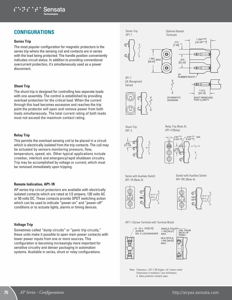
CONFIGURATIONS
Series TripThe most popular configuration for magnetic protectors is the series trip where the sensing coil and contacts are in series with the load being protected. The handle position conveniently indicates circuit status. In addition to providing conventional overcurrent protection, it’s simultaneously used as a power disconnect.
Shunt TripThe shunt trip is designed for controlling two separate loads with one assembly. The control is established by providing overload protection for the critical load. When the current through this load becomes excessive and reaches the trip point the protector will open and remove power from both loads simultaneously. The total current rating of both loads must not exceed the maximum contact rating.
Relay TripThis permits the overload sensing coil to be placed in a circuit which is electrically isolated from the trip contacts. The coil may be actuated by sensors monitoring pressure, flow, temperature, speed, etc. Other typical applications include crowbar, interlock and emergency/rapid shutdown circuitry. Trip may be accomplished by voltage or current, which must be removed immediately upon tripping.
Remote Indication, AP1-1RAP series trip circuit protectors are available with electrically isolated contacts which are rated at 1/2 ampere, 120 volts AC or 50 volts DC. These contacts provide SPDT switching action which can be used to indicate “power-on” and “power-off” conditions or to actuate lights, alarms or timing devices.
Voltage TripSometimes called “dump circuits” or “panic trip circuits,” these units make it possible to open main power contacts with lower power inputs from one or more sources. This configuration is becoming increasingly more important for sensitive circuitry and denser packaging in automation systems. Available in series, shunt or relay configurations.
Series TripAP1-1
[ ] 6 - 32 x .187 4.75SCREWNO. 6 LOCKWASHER
SINGLE POLE1.780 45.21MAX.
MULTIPOLE1.950 49.53MAX.
DIM. FROMBACK OFPANEL.
]
]
]
]
AP7-1 (Screw Terminal with Terminal Block)
.43811.13[ ]
Shunt TripAP1-3
NCNO
C NCNO
C
Switch with Auxiliary SwitchAP1-1RC (Note A)
NCNO
C NCNO
C
Series with Auxiliary SwitchAP1-1R (Note A)
Note: Tolerance ± .031 [.79] Angles: ±5° unless noted. Dimensions in brackets [ ] are millimeters. A. Main protector contacts open.
.43811.13[ ]
.130±.010
3.30±.25.076±.010 DIA. 1.93±.25] ] ] ]
Relay Trip (Note A)AP1-4 (Relay)
UP1-1 (UL Recognized Series)
1.350±.050
.312
.875
2X RUBBER BOOT
BOOT REMOVEDFOR CLARITY
SCHEMATICDIAGRAM
1.012
34.29±1.277] ]
1.562 MAX.39.67] ]
7.92] ]
22.22] ]
25.70] ]
Optional Booted Terminals
AP Series - Configurations http://airpax.sensata.com75
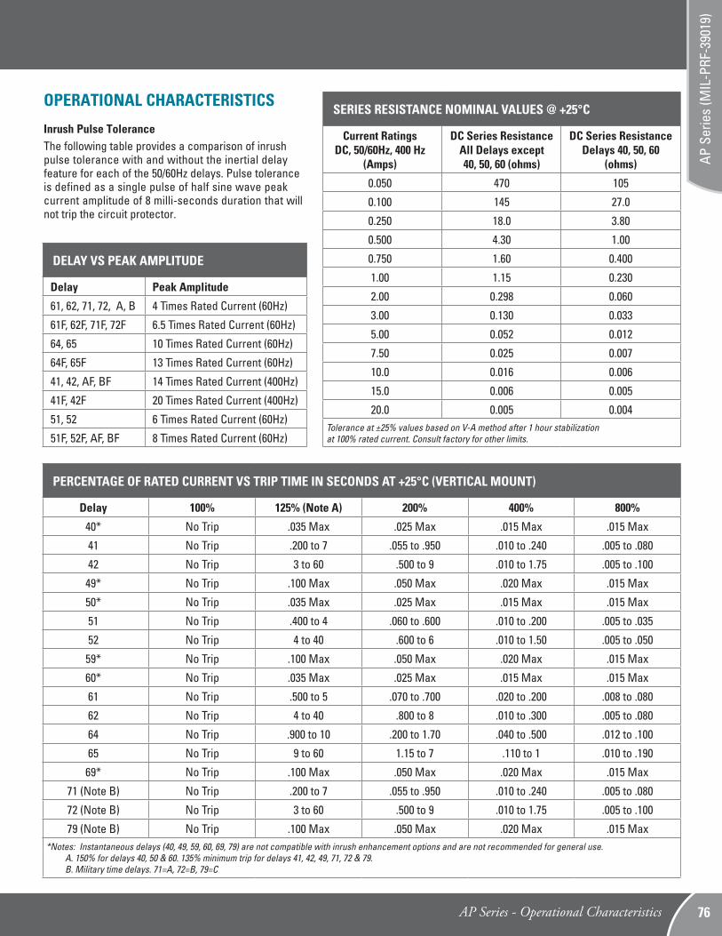
OPERATIONAL CHARACTERISTICS Inrush Pulse ToleranceThe following table provides a comparison of inrush pulse tolerance with and without the inertial delayfeature for each of the 50/60Hz delays. Pulse tolerance is defined as a single pulse of half sine wave peak current amplitude of 8 milli-seconds duration that will not trip the circuit protector.
SERIES RESISTANCE NOMINAL VALUES @ +25°C
Current Ratings DC, 50/60Hz, 400 Hz
(Amps)
DC Series Resistance All Delays except 40, 50, 60 (ohms)
DC Series Resistance Delays 40, 50, 60
(ohms)
0.050 470 105
0.100 145 27.0
0.250 18.0 3.80
0.500 4.30 1.00
0.750 1.60 0.400
1.00 1.15 0.230
2.00 0.298 0.060
3.00 0.130 0.033
5.00 0.052 0.012
7.50 0.025 0.007
10.0 0.016 0.006
15.0 0.006 0.005
20.0 0.005 0.004Tolerance at ±25% values based on V-A method after 1 hour stabilization at 100% rated current. Consult factory for other limits.
PERCENTAGE OF RATED CURRENT VS TRIP TIME IN SECONDS AT +25°C (VERTICAL MOUNT)
Delay 100% 125% (Note A) 200% 400% 800%
40* No Trip .035 Max .025 Max .015 Max .015 Max
41 No Trip .200 to 7 .055 to .950 .010 to .240 .005 to .080
42 No Trip 3 to 60 .500 to 9 .010 to 1.75 .005 to .100
49* No Trip .100 Max .050 Max .020 Max .015 Max
50* No Trip .035 Max .025 Max .015 Max .015 Max
51 No Trip .400 to 4 .060 to .600 .010 to .200 .005 to .035
52 No Trip 4 to 40 .600 to 6 .010 to 1.50 .005 to .050
59* No Trip .100 Max .050 Max .020 Max .015 Max
60* No Trip .035 Max .025 Max .015 Max .015 Max
61 No Trip .500 to 5 .070 to .700 .020 to .200 .008 to .080
62 No Trip 4 to 40 .800 to 8 .010 to .300 .005 to .080
64 No Trip .900 to 10 .200 to 1.70 .040 to .500 .012 to .100
65 No Trip 9 to 60 1.15 to 7 .110 to 1 .010 to .190
69* No Trip .100 Max .050 Max .020 Max .015 Max
71 (Note B) No Trip .200 to 7 .055 to .950 .010 to .240 .005 to .080
72 (Note B) No Trip 3 to 60 .500 to 9 .010 to 1.75 .005 to .100
79 (Note B) No Trip .100 Max .050 Max .020 Max .015 Max*Notes: Instantaneous delays (40, 49, 59, 60, 69, 79) are not compatible with inrush enhancement options and are not recommended for general use. A. 150% for delays 40, 50 & 60. 135% minimum trip for delays 41, 42, 49, 71, 72 & 79. B. Military time delays. 71=A, 72=B, 79=C
DELAY VS PEAK AMPLITUDE
Delay Peak Amplitude
61, 62, 71, 72, A, B 4 Times Rated Current (60Hz)
61F, 62F, 71F, 72F 6.5 Times Rated Current (60Hz)
64, 65 10 Times Rated Current (60Hz)
64F, 65F 13 Times Rated Current (60Hz)
41, 42, AF, BF 14 Times Rated Current (400Hz)
41F, 42F 20 Times Rated Current (400Hz)
51, 52 6 Times Rated Current (60Hz)
51F, 52F, AF, BF 8 Times Rated Current (60Hz)
AP Series - Operational Characteristics 76
AP S
erie
s (M
IL-P
RF-3
9019
)
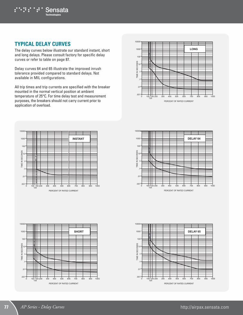
TYPICAL DELAY CURVESThe delay curves below illustrate our standard instant, short and long delays. Please consult factory for specific delay curves or refer to table on page 87.
Delay curves 64 and 65 illustrate the improved inrushtolerance provided compared to standard delays. Not available in MIL configurations.
All trip times and trip currents are specified with the breaker mounted in the normal vertical position at ambient temperature of 25°C. For time delay test and measurement purposes, the breakers should not carry current prior to application of overload.
10000
1000
100
10
1
.1
.01
.0010 100 150 200 300 400 500 600 700 800 900 1000
PERCENT OF RATED CURRENT125
TIM
E IN
SEC
ON
DS
INSTANT
MA
Y
TR
IPM
AY
T
RIP
10000
1000
100
10
1
.1
.01
.0010 100 150 200 300 400 500 600 700 800 900 1000
PERCENT OF RATED CURRENT135
TIM
E IN
SEC
ON
DS
SHORT
MA
Y
TR
IPM
AY
T
RIP
10000
1000
100
10
1
.1
.01
.0010 100 150 200 300 400 500 600 700 800 900 1000
PERCENT OF RATED CURRENT135
TIM
E IN
SEC
ON
DS
LONG
MAY
TRI
P
10000
1000
100
10
1
.1
.01
.0010 100 150 200 300 400 500 600 700 800 900 1000
PERCENT OF RATED CURRENT125
TIM
E IN
SEC
ON
DS
DELAY 64
MAY
TRI
PM
AY T
RIP
10000
1000
100
10
1
.1
.01
.0010 100 150 200 300 400 500 600 700 800 900 1000
PERCENT OF RATED CURRENT125
TIM
E IN
SEC
ON
DS
DELAY 65
MAY
TRI
PM
AY T
RIP
AP Series - Delay Curves http://airpax.sensata.com77
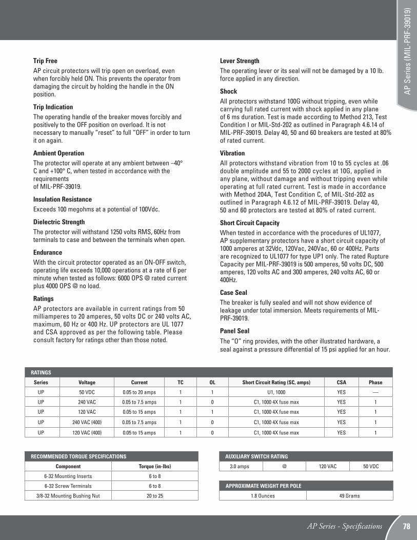
Lever StrengthThe operating lever or its seal will not be damaged by a 10 lb. force applied in any direction.
ShockAll protectors withstand 100G without tripping, even while carrying full rated current with shock applied in any planeof 6 ms duration. Test is made according to Method 213, Test Condition I or MIL-Std-202 as outlined in Paragraph 4.6.14 of MIL-PRF-39019. Delay 40, 50 and 60 breakers are tested at 80% of rated current.
VibrationAll protectors withstand vibration from 10 to 55 cycles at .06 double amplitude and 55 to 2000 cycles at 10G, applied inany plane, without damage and without tripping even while operating at full rated current. Test is made in accordancewith Method 204A, Test Condition C, of MIL-Std-202 asoutlined in Paragraph 4.6.12 of MIL-PRF-39019. Delay 40,50 and 60 protectors are tested at 80% of rated current.
Short Circuit Capacity When tested in accordance with the procedures of UL1077, AP supplementary protectors have a short circuit capacity of 1000 amperes at 32Vdc, 120Vac, 240Vac, 60 or 400Hz. Parts are recognized to UL1077 for type UP1 only. The rated Rupture Capacity per MIL-PRF-39019 is 500 amperes, 50 volts DC, 500 amperes, 120 volts AC and 300 amperes, 240 volts AC, 60 or 400Hz.
Case SealThe breaker is fully sealed and will not show evidence of leakage under total immersion. Meets requirements of MIL-PRF-39019.
Panel SealThe “O” ring provides, with the other illustrated hardware, a seal against a pressure differential of 15 psi applied for an hour.
Trip FreeAP circuit protectors will trip open on overload, even when forcibly held ON. This prevents the operator from damaging the circuit by holding the handle in the ON position.
Trip IndicationThe operating handle of the breaker moves forcibly and positively to the OFF position on overload. It is not necessary to manually “reset” to full “OFF” in order to turn it on again.
Ambient OperationThe protector will operate at any ambient between –40° C and +100° C, when tested in accordance with the requirements of MIL-PRF-39019.
Insulation ResistanceExceeds 100 megohms at a potential of 100Vdc.
Dielectric StrengthThe protector will withstand 1250 volts RMS, 60Hz fromterminals to case and between the terminals when open.
EnduranceWith the circuit protector operated as an ON-OFF switch, operating life exceeds 10,000 operations at a rate of 6 per minute when tested as follows: 6000 OPS @ rated current plus 4000 OPS @ no load.
RatingsAP protectors are available in current ratings from 50 milliamperes to 20 amperes, 50 volts DC or 240 volts AC, maximum, 60 Hz or 400 Hz. UP protectors are UL 1077 and CSA approved as per the following table. Please consult factory for ratings other than those noted.
AUXILIARY SWITCH RATING
3.0 amps @ 120 VAC 50 VDC
APPROXIMATE WEIGHT PER POLE
1.8 Ounces 49 Grams
RECOMMENDED TORQUE SPECIFICATIONS
Component Torque (in-lbs)
6-32 Mounting Inserts 6 to 8
6-32 Screw Terminals 6 to 8
3/8-32 Mounting Bushing Nut 20 to 25
RATINGS
Series Voltage Current TC OL Short Circuit Rating (SC, amps) CSA Phase
UP 50 VDC 0.05 to 20 amps 1 1 U1, 1000 YES —
UP 240 VAC 0.05 to 7.5 amps 1 0 C1, 1000 4X fuse max YES 1
UP 120 VAC 0.05 to 15 amps 1 1 C1, 1000 4X fuse max YES 1
UP 240 VAC (400) 0.05 to 7.5 amps 1 0 C1, 1000 4X fuse max YES 1
UP 120 VAC (400) 0.05 to 15 amps 1 0 C1, 1000 4X fuse max YES 1
AP Series - Specifications 78
AP S
erie
s (M
IL-P
RF-3
9019
)
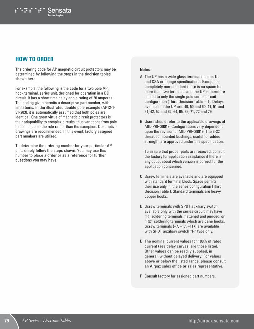
HOW TO ORDER
The ordering code for AP magnetic circuit protectors may be determined by following the steps in the decision tables shown here.
For example, the following is the code for a two pole AP, hook terminal, series unit, designed for operation in a DC circuit. It has a short time delay and a rating of 20 amperes. The coding given permits a descriptive part number, with limitations. In the illustrated double pole example (AP12-1-51-203), it is automatically assumed that both poles are identical. One great virtue of magnetic circuit protectors is their adaptability to complex circuits, thus variations from pole to pole become the rule rather than the exception. Descriptive drawings are recommended. In this event, factory assigned part numbers are utilized.
To determine the ordering number for your particular AP unit, simply follow the steps shown. You may use this number to place a order or as a reference for further questions you may have.
Notes:
A The UP has a wide glass terminal to meet UL and CSA creepage specifications. Except as completely non-standard there is no space for more than two terminals and the UP is therefore limited to only the single pole series circuit configuration (Third Decision Table – 1). Delays available in the UP are: 40, 50 and 60; 41, 51 and 61; 42, 52 and 62; 64, 65, 69, 71, 72 and 79.
B Users should refer to the applicable drawings of MIL-PRF-39019. Configurations vary dependent upon the revision of MIL-PRF-39019. The 6-32 threaded mounted bushings, useful for added strength, are approved under this specification.
To assure that proper parts are received, consult the factory for application assistance if there is any doubt about which version is correct for the application concerned.
C Screw terminals are available and are equipped with standard terminal block. Space permits their use only in the series configuration (Third Decision Table ). Standard terminals are heavy copper hooks.
D Screw terminals with SPDT auxiliary switch, available only with the series circuit, may have “R” soldering terminals, flattened and pierced, or “RC” soldering terminals which are cane hooks. Screw terminals (–7, –17, –117) are available with SPDT auxiliary switch “R” type only.
E The nominal current values for 100% of rated current (see delay curves) are those listed. Other values can be readily supplied, in general, without delayed delivery. For values above or below the listed range, please consult an Airpax sales office or sales representative.
F Consult factory for assigned part numbers.
AP Series - Decision Tables http://airpax.sensata.com79

First Decision
Type
1
Second Decision (Note C)
Single pole unit,mounted with 3/8 threaded bushing
Two pole unit, bushing plus (2) 6-32threaded inserts
Three pole unit, bushing plus (2) 6-32 threaded units
1
12
112
7
17
117
2
Poles
HookTerminals
ScrewTerminals
Fourth Decision4
Hz and Delay
-40
-41
-42
-49
-50
-51
-52
-59
-60
-61
-62
-64
-65
-69
-71
-72
-79
400Hz 150% instant trip*
400Hz short time delay
400Hz long time delay
400Hz 135% instant trip*
DC 150% instant trip*
DC short time delay
DC long time delay
DC 125% instant trip*
50/60Hz 150% instant trip*
50/60Hz short time delay
50/60Hz long time delay
50/60Hz high pulse, short time delay (50/60Hz only)
50/60Hz high pulse,long time delay (50/60Hz only)
50/60Hz 125% instant trip*
DC, 50/60Hz, 400Hz short time delay 135% trip
DC, 50/60Hz,400Hz long time delay 135% trip
DC, 50/60Hz,400Hz instant time delay 135% trip*
For addition of inertial delay, add an “F” to any delaynumber. Except 40, 50 & 60.
*Instantaneous delays are not compatible withinrush enhancement options and are not recommendedfor general use.
Fifth Decision (Note E)5
Nominal Amperage Rating
Code
-051
-101
-201
-251
-401
-501
-601
-751
-102
-1251
-1751
-202
-252
-302
-502
-702
-752
-802
-103
-123
-153
-173
-203
Amperes
.050
.100
.200
.250
.400
.500
.600
.750
1.000
1.250
1.750
2.000
2.500
3.000
5.000
7.000
7.500
8.000
10.000
12.000
15.000
17.000
20.000
See page 61 for maximum voltage ratings.
Note: Standard current ratings listed. For other ratings, please consult the factory.
AP12 -1 -51-203-FM
Third Decision3
Internal Con�guration
Multi-pole units with mixed construction, poles numbered
-0
-1
-1R(Note D)
-1RC(Note D)
-3
-4
Switch Only(Omit 4th and 5th Decisions)
Series
Series with Auxiliary Switchwith pierced pin terminals
Series with Auxiliary Switchwith cane hook terminals
Shunt
Relay (5 amps max coil rating)
left to right when viewed from terminal end (Note F).
Fully sealed magneticcircuit protector
Underwriters' Laboratoriesrecognized circuit supplementary protector
/1 through /6 QPL perMIL-PRF-39019
AP
UP(Note A)
AP - MIL(Note B)
Optional
FM Approved (Factory Mutual Research)
6
Add –FM to part number to indicate FM approval. FM approval is available forSingle Pole, Series Trip, UP type units only.TA = –40ºC to +65ºCUnits < 10A are rated CL 1, DIV 2, Group ABCD, T6Units > 10A are rated CL 1, DIV 2, Group ABCD, T4A
Example:
AP Series - Decision Tables 80
AP S
erie
s (M
IL-P
RF-3
9019
)

©2013 Sensata Technologies, Inc. All rights reserved worldwide. The following data sheet is an excerpt from our Airpax™ Power Protection Catalog, Literature # 2455005000, printed in the USA, May 9th, 2013.
Important Notice: Sensata Technologies reserves the right to make changes to, or to discontinue, any product or service identified in this publication without notice. Before placing orders, users should obtain the latest version of the relevant information to verify that the information being relied upon is current.
Sensata Technologies assumes no responsibility for customers’ product designs or applications. Users must determine the suitability of the Sensata device described in this publication for their application, including the level of reliability required. Many factors beyond Sensata’s control can affect the use and performance of a Sensata product in a particular application, including the conditions under which the product is used and the time and environmental conditions in which the product is expected to perform. As these factors are uniquely within the user’s knowledge and control, it is essential that the user evaluate the Sensata product to determine whether it is fit for a particular purpose and suitable for the user’s application.
Sensata Technologies products are sold subject to Sensata’s Terms and Conditions of Sale which can be found at: www.sensata.com/terms.htm
http://airpax.sensata.com/
Sensata Technologies Inc.529 Pleasant Street Attleboro, MA 02703, USA Phone: +1 508-236-3287