magnetic electrostatic plasma codinementi - hellblazer · magnetic electrostatic plasma confinement...
TRANSCRIPT
Plasma Phys. Control. Fusion 36 (1994) 1539-1593. Printed in the UK
REVIEW ARTICLE
Magnetic electrostatic plasma codinementi
T J Dolan Idaho National Engineering Laboratory, EG&G Idaho, PO Box 1625, Idaho Falls, ID 83415-3880, USA
Received 20 December 1993, in final form 25 March 1994
Abstrad. Electrostatic plasma confinement and magnetic electrostatic plasma confinement (MEPC) have been studied for four decades. The multiple potential well hypothesis, postulated to explain high neutron yields from Hinch’s colliding beam experiment, has been supported by several pieces of evidence, but results were inconclusive. Magnetic shielding of the grid was developed to reduce the required beam current and to prevent grid overheating. Electrostatic plugging of magnetic cusps evolved to a similar confipuration. Due to low budgets, early MEPC experiments used spindle cusps, which are poor for plasma confinement. Later experiments used multipole cusps or a linear set of ring cusps, which have larger volnmes of field-free plasma. To keep the self-shielding voltage drop A+ S 100 kV, the electron density n, in the anode gap should be less than about 10’9m-3. The central plasma density can be an order of magnitude higher. The ATOLL toroidal quadrupole had anomalous electron energy transport, but the Jupiter-2M linear set of ring cusps achieved a transport rate about a factor of two above the classical rate. With near-classical transport, a power gain ratio Q=10 is predicted for a reactor with rp=3m, B,=6T, and applied voltage +, =400 kV. Besides producing electricity and synthetic fuels, MEPC reactors could be used for heavy ion beams sources and neutIon generators. The main issues of concern for MEPC reactor development are electron transport, plasma purity and electrode alignment and voltage holding.
List of parameters
(SI Units are used, unless otherwise noted.)
a = half-width of the anode gap A =area A,,,, = effective area for plasma loss out of magnetic cusps A =magnitude of the magnetic vector potential B =magnetic field (magnetic induction) B. =magnetic field in the anode gap Bb = [2p,,nk(T, + T,)]ln = boundary magnetic field
- B, =peak magnetic field at the coil B, =point cusp magnetic field c = speed of light c, =ion acoustic speed
t This work was supported in part by the US Department of Energy, Office of Energy Research, contract DE-AC07-76ID01570.
0741-3335/94/101539+ 55 $19.50 0 1994 IOP Publishing Ltd 1539
1540 T J Dolan
g h I Idiff
1, k
‘P R
=grid wire diameter =electron diffusion coefficient due to collisions with neutral atoms =electron diffusion coefficient due to collisions with ions = maximum diffusion coefficient =total collisional dausion coefficient = electronic charge =fraction of incident neutrals which are ionized (instead of charge exchanged) =fraction of fusion product alpha energy W, transferred to electrons =fraction of fusion product alpha energy W, transferred to ions =geometrical factor having dimensions of reciprocal length = spacing between grid wire centres =width of the anode along the magnetic field direction =electron current from electrodes into the plasma = electron diffusion current = electron injection current = wavenumber = 2n/h = Boltzmann constant = subscript.denoting either electrons or ions =length between ends of a linear cusp device =distance between adjacent ring cusps = electron mass = number of pairs of multipole conductors = N / 2 = ion mass = plasma electron density =uncompensated electron density at centre of anode gap = Brillouin density =‘particle density of species k = central core electron density =total number of electrons = central plasma density = initial plasma density (pulsed electrostatic confinement) =ion density in the anode gap =trapped cold electron density in anode region = number of multipole cusp gaps
=electron heating by the edge electric field that affects the central plasma = ion heating by plasma waves =radiative power loss = electron power loss to plasma waves = canonical angular momentum = (fusion power)/(input power)
= radius = point cusp anode radius =plasma boundary radius = virtual electrode radius (electrostatic confinement and Penning trap) = radius of plasma boundary surface in point cusp = approximate plasma radius at magnetic field boundary = accelerating grid radius (electrostatic confinement)
= (zl/z,,)’n
= OZpE/62.

Magnetic electrostatic plasma confinement 1541
R =magnetic mirror ratio R =ring cusp anode radius S =plasma surface area Si = ionization source S, T,, =electron temperature (keV) T, =electron temperature T,, =central electron temperature U =ion speed uia = ion speed in anode gap U =electron velocity uvn = electron density-gradient drift velocity V = plasma volume w =characteristic half-width of the electron distribution in anode region W, = average energy acquired along the slope of the potential well by ions We =electron energy Wi = ion energy W,,, = average electron energy loss per incident neutral atom due to ionization W, x = r l R v =&JZ
= volume-averaged neutral input rate
=ion energy perpendicular to the radial direction
zk = charge number Z ,
(Y
y 6 6 A'$ AT E E
sg E, =permittivity of free space < =global Brillouin ratio In A = Coulomb logarithm A =wavelength p,, =permeability of free space vei pa pb p . = electron Larmor radius p o pi = ion Larmor radius p1 =inner electron turning radius p2 =outer electron turning radius (ou) = DT fusion reaction rate parameter
= 1 for electrons and 112 for ions
= a parameter depending on TJc =&action of current intercepted by the grid = the effective half-width of the cusp gap for plasma loss = a function of pl, p z = self-shielding voltage drop in anode gap =thickness of plasma edge region = (trapped electron pump-out rate)/(diffusion rate) =effective open fraction of wire mesh grid =geometrical open fraction of wire mesh grid
= electron-ion momentum-transfer collision frequency = electron Larmor radius in anode gap = electron Larmor radius at plasma boundary
= electron Larmor radius in point cusp

1542 T J Dolan
z1 =electron loss time by diffusion across the magnetic field z =pulse length z, = characteristic collision time for electrons or ions zmnd =time for heat loss by conduction zdiE =characteristic time for electron diffusion across the magnetic field re = electron lifetime or confinement time rEEl = electron perpendicular energy confinement time zE,, = electron parallel energy confinement time rei = electron-ion collision time res = electron-ion equipartition time zi =ion confinement time zo = electron collision time ztnp =time for central plasma free electrons to be trapped by edge magnetic field (PA = applied voltage +, += = electron potential barrier q5! =ion potential barrier q5p wc = cyclotron frequency wCe = electron cyclotron frequency wCi = ion cyclotron frequency wge = electron plasma frequency-
=potential barrier for electrons or ions
= plasma potential = q5i + A +
1. Introduction
Magnetic electrostatic plasma confinement (MEPC) uses electrostatic fields to enhance plasma confinement by open magnetic fields. The purpose of this review is to describe:
(i) the evolution of MEPC from electrostatic plasma confinement and from open magnetic confinement systems;
(ii) MEPC theory; (i) experimental observations; (iv) fusion reactor concepts; (v) salient issues.
MEPC devices have also been called ‘electromagnetic traps’, ‘magnetoelectro- static traps’, ‘magnetic inertial-electrostatic confinement’, ‘electrostatically plugged cusps’, ‘kinetic-electric-magnetic plasma confinement (KEMP)’, ‘electric-magnetic confinement’, ‘Polywell“’, and ‘modified Penning trap’. Discussions of electrostatic field applications in tandem mirrors, bumpy tori and tokamak helicity injection are beyond the scope of this review.
1.1. Electrostatic plasma confinement
1.1.1. Virtual electrode formation. Lavrent’ev [l] first proposed electrostatic plasma confinement on 22 June 1950, and magnetic field enhancement of electrostatic plasma confinement in March 1951. In the early 1960s Farnsworth [2] proposed electrostatic plasma confinement for the production of fusion reactions, based upon

Magnetic electrostatic plasma confinement 1543
Figure 1. Concentric spherical electrodes used for electrostatic plasma confinement
his experience with spherical multipactor vacuum tubes. Lavrent’ev [3] developed a theory of charged particle flow and focusing in plane and spherical geometries. Budker [4] calculated the fusion reaction rate that could be attained by trapping ions in the negative electrostatic charge of an electron beam. Early electrostatic plasma confinement experiments 151 consisted of concentric spherical wire mesh electrodes, which accelerated charged particles inwards to produce a virtual electrode inside the central sphere (figure 1). Charged particles of the opposite sign would be attracted into the virtual electrode. For example, if electrons were injected into the sphere, they would produce a virtual cathode [6]. which would attract positive ions. In order to minimize grid current and heating, it is desirable to have the grid mesh nearly transparent to the charged particle flows.
Deflections of injected particles towards nearby grid wires decrease the effective open area of the grid by an amount [7]
E / E ~ = (1 - 1 / 1 6 ~ ~ : ~ ) ~ (1) where E is the effective open fraction of the grid, E% = (g - d)’/g2 is the geometrical open fraction of the grid. g is the spacing between grid wire centres (square mesh) and d is the grid wire diameter. For example, if g = 4 mm and d = 0.2 mm, then ~ ~ = 0 . 9 0 and E =0.865. The circulating current I, is related to the current I intercepted by the grid wires by the equation
I J I = 2 ~ / ( 1 - E’). (2) For the example case with E = 0.865, the theoretical value of IJI = 6.9. Thus, for a highly open grid the circulating current can be about an order of magnitude greater than the grid current.
Lavrent’ev and co-workers [8] studied ion generation by oscillating electrons and ion focusing with spherical grids. Probe measurements inside a 5 cm radius spherical cathode indicated a strong focusing of injected ions down to radii < 1 cm. The focused ion current density was 12-25 mA cm-’ at 4 kV in 0.13 Pa of argon [9-111. A passing ion density of 1017m-3was deduced from current probe data [12].
Hirsch [13] injected electrons into a spherical wire mesh anode, and used an electron beam probe to measure the potential well depth produced by the virtual

1544 T J Dolan
cathode. He found that deep, negative potential wells were easily produced and maintained. He also observed some oscillations of the discharge at frequencies -100 MHz.
For the case of electron injection to produce a virtual cathode, there are two great dsculties: the very high currents required [I41 and grid wire overheating. Better conhement could. be obtained for the case of ion injection into the accelerating grid, producing a virtual anode.
Hockney [U] simulated the formation of a virtual electrode in cylindrical geometry by solving Poisson's equation for a case with only ions, represented by 2000 charged rods, and showed that the virtual electrode is stable for long periods of time. In a simulation with both electrons and ions, however, Barnes 1161 found that electrons trapped in the virtual anode tend to wash out the anode potential, so that the virtual anode gradually disappears. Only in cases with very high ion currents did the virtual anode persist. He concluded that the electrostatioinertial confinement device, as originally conceived, was unlikely to confine a fusion plasma adequately. Porter and Klevans [17] investigated the stability of electrons Bowing among ions within a virtual anode, and concluded that the electrons are marginally stable to the two-stream instability.
1.1.2. Multiple well hypothesis. Hirsch [le] observed high DT neutron yields (up to 2 X IO" s-') from a steady-state device using ion injection from six ion guns. These neutron yields exceeded the predictions of simple theories. One hypothesis to account for the observed neutron yields is the formation of multiple, concentric spherical potential wells of altemate sign inside the central sphere, with much higher circulating currents in the inside layers, as illustrated in figure 2. According to such a model, ions trapped in interior layers could have high energies, circulating currents
Q .' o
I cathode D , . ' , . .
0 .....-.
ions
o(r) electrons
r - Figure 2. Multiple virtual electrodes inside the accelerating grid.

Magnetic electrostatic plasma confinement 1545
" 2 -1 0 ' I '2
Radial Position
Figure 3. The results of a neutron collimation study at -9OkV, 20mA and p = 1 Pa (deuterium) [18].
and densities, and could produce significant fusion energy yields. Hu and Klevans [19] modelled multiple wells for cases with zero angular momentum (perfectly radial motion). They calculated the attainable current amplification ratio (the ion current inside virtual anode/ion beam current outside virtual anode), and found that values as high as 150 were possible if large trapped ion populations could be confined in the outer region.
The following observations appear to be consistent with the multiple potential well hypothesis:
(i) high neutron yield; (ii) peaks in the curve of neutron yield versus radius measured by Hirsch [18] as
(iii) peaks in the curve of electron bremsstrahlung yield versus radius measured shown in figure 3;
by Hirsch [18] as shown in figure 4:
Figure 4. Electron bremssstrahlung yield versus radial position, as measured by Hirrch [181.

1546 T J Dolan ylm 0.5 0 -0.5 0 0.5 1
-1 X
Figure 5. Theoretical variation of dimensionless electrostatic potential Y versus dimen- sionless radius X, for a case with applied voltage=500V, current=125mA, grid gransparency=90%, and very small spreads of energy and angular momentum. A double well is apparent.
(iv) a large time-delayed puff of gas after beam injection cut-off measured by Hirsch [18];
(v) theoretical studies by Cherrington et nl [ZO] for cases with injected beams having narrow spreads of energy and angular momentum show a slight double well, as illustrated in figure 5;
(vi) electron beam probe studies by Swanson et a1 [21,22] of a spherical electrostatic confinement device at low pressures;
(vii) peaks in the curve of electron density versus radius (figure 6) measured by laser heterodyne studies in a cylindrical electrostatic confinement device by Meeker and co-workers [23.24]. This figure is for the case of electron injection; similar, less pronounced peaks were observed during ion injection.
Electron Density
-10 0 10 Radius, mm
Figure 6. Electron density versus radius measured by Meeker el a1 using a laser heterodyne interferometer during electron injection into a cylindrical grid with radius 40 mm, at 16 A circulating current, p = 1 Pa (deuterium) [24].

Magnetic electrostatic plasma confinement 1547
Other studies, however, have yielded results less indicative of multiple potential wells. Imel [25] and Black and Klevans [26] developed theoretical models of the electrostatic potential profile and electron and ion density profiles, using distribution functions tailored to various experimental conditions. They analysed three cases [27]
(i) Ion beam injection at very low pressures (the Hirsch experiment). They concluded that multiple deep potential wells would probably not form under the conditions of the Hirsch experiment.
(ii) Ion injection at higher pressures, where charge exchange produces a broad spread of ion energies (several experiments). They predicted a central plasma density close to the value measured in the Penn State experiment (2 X l O I 5 III-~), and found that substantial potential wells could be formed for p < 0.13 Pa (1 mTorr).
(iii) Electron injection at low pressures (the Swanson er al and Black and Robinson experiments). They predicted deep potential wells for high perveance cases, as observed by Swanson et ul, and shallow potential wells for low perveance cases, as observed by Black and Robinson [ZS].
They did not report any cases with finite angular momentum and multiple potential wells.
Gardner and colleagues [29] continued the ion beam experiment of Hirsch and used a microwave cavity to measure the number of free electrons in the plasma, but they were unable to reproduce the neutron yields observed by Hirsch. Baxter and Stewart [30] predicted nuetron yields close to those observed in the Hirsch experiment by analysing ionization and charge exchange in the ion beam. without invoking the multiple potential well hypothesis.
Peterson and Oleson [31] studied hemispherical focusing of a low-energy ion beam in a double-beam plasma device. When the ion beam energy exceeded 7, the beam ions were slowed down by a potential hill (virtual anode) at the focus. They observed formation of a dense group of cold electrons (0.8 eV), which appeared to ride along with the ion beam, in addition to the background plasma electrons (4.5 eV) and primary electrons from filaments. Such cold electrons could tend to wash out potential wells.
Nadler et a1 [32] built a collimated solid state proton detector to observe protons resuIting &om DD fusion reactions in a spherical electrostatic confinement device. The energy shifts produced by aluminium and lead foils verified that they were detecting 3 MeV protons. At 12 mA cathode current, 30 kV voltage, in 0.5 Pa of deuterium fusion reactions between the focused ion beam and the background plasma were dominant. In future experiments at higher currents, the higher proton count rates should permit improved angular resolution, which could facilitate the detection of multiple potential wells.
1.1.3. Regimes of operation. Miley et a1 [33] distinguished three regimes of ion injection into an inertial electrostatic conhement (IEC) device:
(1) A discharge mode. In this mode a self-sustaining plasma discharge (like a glow discharge) generates ions throughout the chamber volume. Free electrons are produced by ionization and by secondary emission from grids. This mode requires comparatively high gas pressures (>1 Pa), which result in substantial charge exchange rates.
(2) An emitter mode, based on a patent by Hirsch and Meeks [34]. In this mode

1548 T J Dolan
primary electrons from thermionic cathodes orbit in and out of an intermediate grid, ionizing background gas, at pressures typically 0.1-1 Pa. Ions produced by ionization are then accelerated into the central cathode. This mode was used in experiments by Meeker and co-workers [24,35] to measure density profiles. Using this mode with deuterium gas, Miley et a1 [33] observed steady-state neutron yields of lo5 neutrons per second.
(3) A beam injection mode. High-energy ion beams are focused into the central region, to produce a high-density virtual anode. This mode, which can operate at the lowest pressures, was used by Hirsch' to obtain high neutron yields. This mode is most suitable for fusion reactors, because the low pressure minimizes ion energy loss by charge exchange.
1.1.4. Reactor prospects. For steady state operation with radiative cooling of a tungsten grid intercepting 1% of the ion current and focusing the ions to a virtual anode at radius r, = 0.01R. Lavrent'ev [36] found that a grid radius R > 10 m would be needed in order to achieve a net energy output. For the case of a puked reactor the required grid radius is given by
R > 0.001yzp&.(r0/R)/4d (3) where y is the fraction of current intercepted by the grid, zP is the pulse length, d is the grid wire diameter and +A is the applied voltage (kV). For a case with y = 0.01, r,/R = 0.01,
It is also possible to focus the injected ions temporally by increasing the voltage during injection [37]. Ions starting out later are accelerated more and catch up with the early ions, so that the ion density at the focus is much higher than the steady-state value for continuous injection. For example, starting with background plasma at radii between R = 1 m and 2 m with density no = lo'* mW3, the focused density would be n = 6 X loz m-3; The converging ion beams could also be used to compress and ignite inertial confinement fusion target pellets.
Although purely electrostatic plasma confinement might be attractive for a fusion reactor with a large radius or short pulse length, overheating of the grid wires is a serious concern. One way to reduce the heat load from charged particle bombard- ment of the grid wires is to shield them magnetically by passing high currents through them, as illustrated in figure 7. If electrons are injected between the grid wires, very few will contact the grid wires directly. Some electrons will gradually become trapped in the magnetic field and diffuse to the grid wires, but this process is orders of magnitude slower than direct bombardment. This magnetic shielding of grid wires, here called MEPC, has also evolved kom open magnetic confinement systems.
= 100 kV, zP = 0.1 s and d = 0.001 m, this equation gives R > 2.5 m.
E y r e 7. Cutaway view of a few grid wires with currents flowing out (+) and into (-) the plane of the drawing. The ellipses represent magnetic field lines.

Magnetic electrostatic plasma conmement 1549
1.2. Open magnetic confinement systems
Minimum43 magnetic confinement systems offer good MHD stability, but suffer from rapid plasma loss along magnetic field lines 1381. Conhement times in simple magnetic mirror ceUs are typically of the order of ion-ion scattering times, and confinement times in magnetic cusps are tens of transit times, which typically makes
Q =(fusion power)/(input power) C 1 (4)
for ordinary mirrors and cusps. In order to attain Q > 10 without requiring very large size or extremely high magnetic induction, it is desirable to find a means for plugging end losses from magnetic mirrors and cusps. Many means of Q- enhancement for open magnetic confinement systems have been studied, including tandem mirrors, multiple mirrors, field reversed mirrors, Tormac, Sumac, plasma rotation, gasdynamic traps. radiofrequency plugging and electrostatic plugging 139,401. Axisymmetric cusps have been suggested as electrostatic end plugs for tandem mirrors 141-431.
Several cusped magnetic fields have been considered for plasma confinement [U], as illustrated in figure 8. The toroidal multipole shown in figure 8 has N = 6
Spindle Cusp
point cusp
ring cusp (line cusp)
omidal Set of Ring Cusps
Cusp-Ended Solenoid
ine cusp
Toroidal Multipole Cusp
xis all line cusps
near Arrangement of Ring Cusps
Figure 8. Magnetic field lines (smooth curves) in some cusped geometries. The symbols X and represent current into and out of the drawing, respectively.

1550 T J D o h
cusps (hexapole). In addition to these configurations, arrays of point cusps on the surfaces of polyhedrons have been studied by Keller and Jones [45] and by Sadowski [46-501. All of these cusp geometries have been considered for electrostatically plugged devices.
For plasma conhement by magnetic cusp fields, the loss area through a ring cusp is approximately 2nR(26), where R is the ring cusp radius and 6 the effective half-width of the cusp gap through which plasma is lost. In a spindle cusp, the loss area through the point cusps is comparable, so the total loss area A,,, = 8nR6. The ion flux into the loss regions is approximately 0.25nu, where U is the ion speed, so the confinement time in an unplugged magnetic spindle cusp device is approximately
z=nVl(0.25nuA,,,,) = VI2mR6 (5 )
where Vis the plasma volume. This time is typically tens of bounce times back and forth inside the central field-free region. Spindle cusps have very small plasma volumes. If 6 -p i , then unfeasibly large R and B would be required for a reactor. If 6 - (pspi)ln (a hybrid gyroradius), as indicated in some cusp experiments and in a computer simulation [51-531, then a reactor using a ‘picket fence’ cusp (such as the spherical cusp and linear set of ring cusps in figure 8) is feasible, but high magnetic fields and large radii are needed [54].
For a linear set of ring cusps (figure 8) with distance Ll between the ring cusps, the plasma volume between cusps is V = d p L l , where rp is the effective plasma radius, and the loss area A,,,, = 4nR6. For this case
z = r ~ L J u R 6 .
This equation, which estimates the plasma loss time by free-flow-out ring cusps with an effective loss width 26 in each ring cusp, will be used later to estimate the effectiveness of electrostatic plugging.
Lavrent’ev and colleagues [5,55l proposed electrostatic plugging of cusps to reduce the loss rate of plasma flowing along magnetic field lines out of the cusp gaps, and conducted early experimental studies of this technique. If the plasma potential is highly negative relative to the walls, the ions will be confined electrostatically. Only electrons will be energetically able to pass through the narrow cusp gaps (plus a few ions in the high-energy tail of the Maxwellian), so the width of the untrapped electron stream flowing through the cusp gap may be reduced to S - p.. Cathodes outside the cusp gap reflect escaping electrons back into the plasma. Such electrostatically plugged cusps are equivalent to magnetic shielding of the grid wires of an electrostatic-inertial confinement device. In electrostatically plugged cusps, the ions no longer flow freely out of orifices, so the free-flow confinement time estimates do not apply. Instead, the ions are confined electrostatically by the potential well of electron space charge, and electron confinement is limited by diffusion across the magnetic field.
Moir discussed the use of electrodes to contain warm plasma for stabilizing open magnetic confinement systems, such as a toroidal quadrupole cusp [56]. The augmentation of toroidal magnetic confinement by strong electrostatic fields was studied by Daugherty ef nl [57] and by Stix [58-601. Jones [61,62] suggested the use of electron or ion injection to create radial electrostatic potential variations, instead of using plugging electrodes.

Magnetic electrostatic plasma confinement 1551
Magnetic
Figure 9. An electrostatically plugged toroidal quadrupole magnetic cusp and the resultant distribution of electrostatic potential 4. The broken line represents the potential with no plasma present.
2. Theory
2.1. Electrostatic potential
Magnetic electrostatic plasma confinement, which may be accomplished with any magnetic cusp configuration, is illustrated in figure 9 for the case of a toroidal quadrupole cusp. High-voltage electrode rings are placed in each of the cusp gaps, as shown. The anodes are biased positive. and the cathodes negative. Operation of the confinement system depends mainly upon the voltage +A applied between the cathode and anode, and little upon the relative location of the 'ground' potential. From figure 9 it is evident that
+ A = + + i + W. (7)
This potential sbape is the same as that of a simple tandem mirror. In a vacuum, the interior of the device will be near the anode potential (broken
curve of figure 9). Plasma may be produced by electron beam injection into low-pressure gas, by rf (radiofrequency) heating, by plasma gun injection, by laser-pellet heating, by neutral beam injection or by other means. Electrons exiting the cusps are reflected by the negative voltage of the cathode, but the exiting ions are not initially confined. Since electrons are lost less rapidly than ions, the plasma develops a slight negative charge, and the plasma potential becomes negative relative to the anodes (the full curve of figure 9). If the anode gaps are narrow enough that their potential is not entirely shielded out by the plasma in the anode regions, then the potential there will be near the anode potential and higher than

1552 T J D o h
Figure 10. Hypothetical equipotential surfaces in the anode region, showing saddlc- shaped electrostatic potential distribution.
the plasma potential, forming a potential hill +j for the remaining ions. Only a slight fractional charge imbalance is required to set up a potential hill many kV high. Then only ions with kinetic energies greater than e& can escape along the magnetic field lines out of the cusps. The two-dimensional potential distribution (figure 10) is saddle-shaped in the anode regions, with the saddle point lying an amount A& below the anode potential.
The potential hill for ions approaching the walls (at anode potential) is even higher, so most ions will go out through the cusp gaps as soon as they acquire enough energy to overcome the barrier +!; no ions acquire enough energy collisionally to surmount the barrier (&; + A + ) and reach the walls. The ions are electrostatically confined in a negative electrostatic potential well produced by a slight charge imbalance. The ion Larmor radius is less significant than usual, because the ions are electrostatically reflected in the boundary layer. The maintenance of a potential difference along the magnetic field lines is facilitated by the boundary condition that the walls are very close to the plasma only in the anode gaps. Some energetic ions are replaced by cold ions as a result of charge exchange with neutral gas.
The central plasma region is uniform in density and temperature, free of electric and magnetic fields, and surrounded by a thin edge layer. The outside boundary of the edge layer is the magnetic surface along which electron orbits graze the anodes, and the inside boundary is the uniform central plasma region. The boundary layer thickness at any location with magnetic induction B is found by magnetic flux conservation to be
Ar ;=a(RB, / rB) , (8)
where a is the anode gap half-width, R is the ring cusp anode radius and r the radius of the boundary layer. If B , = ST, B = lT, R = 4 m, r = 3 m and a = 1.5 mm then Ar = 10 mm. This thickness is much less than the plasma size, so the plasma has a ‘sharp boundary’.

Magnetic electrostatic plasma confinement 1553
Figure 11. Electron orbits near a magnetic cusp. Smooth arcs represent magnetic field lines. Dots represent ions. Electron trajectories are as follows: 1 =reflected off plasma boundary, 2 =passing through anodes and reflected by cathode, 3 =magnetically trapped in boundary layer, 4 = electrostatically trapped by anode potential well.
2.2. Electron orbits
There are several types of electron orbits, illustrated in figure 11:
(I) Electrons that stay in the central plasma and are reflected geometrically from the convex edge layer.
(2) Electrons from the central plasma that can pass through the anode gap regions and be reflected by the cathodes.
(3) Electrons that are magnetically trapped in the edge layer. (Many of these are mirror-reflected away from the cusp gaps.)
(4) Cooler electrons that are electrostatically trapped by the anode potential. Most of these electrons are produced by ionization of incident neutral gas atoms along the slope of the potential well. These trapped electrons are deleterious, because they increase the self-shielding voltage drop A+.
Electrons may be produced by thermionic emission from an electron gun, by secondary emission from the plugging cathodes and by ionization of neutral gas. Much of the injected electron beam is reflected by the plasma and lost to the cathodes. This portion of the injected beam does not contribute to plasma density build-up. Yushmanov [63] found that only a small fraction of the injected beam current is effectively trapped. The time required for plasma density build-up by electron beam injection (many particle confinement times) exceeds the duration of the flat-top magnetic field in some pulsed experiments.
Many of the electrons produced by ionization will be magentically trapped in the edge region. The untrapped electrons will circulate back and forth through the plasma, occasionally passing out through the anodes and being reflected by the potential barrier +e, Coulomb collisions and electric field fluctuations cause diffusion in velocity space. Trapped electrons can become heated and detrapped, and free electrons can be deflected and trapped either magnetically or electrostatically [64].
There are two main electron loss processes: trapping by the magnetic field with subsequent diffusion to the anodes, and collisional diffusion in velocity space over the potential barrier +e with loss to the cathodes. (Loss to the cathodes converts

1554 T J D o h
electron kinetic energy into electricity, returning energy to the power supply.) Recombination with ions is negligible.
2.3. Loss rates ouer potential barriers
The loss rates along the magnetic field by velocity-space diffusion over the potential barriers have been calculated by Cohen et a1 [65]. based on the method of Pastukhov [66]. For a plasma with shgly charged ions, the resulting particle loss rates along the magnetic field are
(dn,/dt),, = -4%G exp( -yx)~(l /yx)l[~'"yw~,G(RZ,) I (9)
(10)
(11)
G(RZ,) = (1 + l/RZ,)'"In{[(l + I/RZk)ln + 1]/[(1 + l/RZ,))'" - l]}
W y , ) = 1 + o.5(dyk)'" exp(yd1- erf(yi")]
where the subscript k denotes either electrons or ions, n, is the particle density, Z, = 1 for the electrons and 1/2 for ions, R is the magnetic mirror ratio, r, is the characteristic collision time for electrons or ions, and y, = z,e&/Tx where z, is the charge number (= 1 for singly charged ions, = -1 for electrons), e is the electronic charge and & is the potential barrier for eectrons or ions (here z, and are,taken to be positive quantities).
=1+ 1/(2y,) - 1/(4y:) + 3/(8y;) +. . .
The energy loss rates along the field are given by
1.5[d(n,Tk)/dt],, = zke+,[l/I(l/yk) + 1.5/yk](dn,/dt),,. (12) A similar estimate of loss rates was made by Sizonenko and Stepanov [67]. These equations give the rate at which particles or energy are lost by electron or ion diffusion in velocity space over their potential barriers +e and &. In view of the exp(-y,) factor in the particle loss equation, the confinement time should increase roughly expontially with y,. Computer simulations by McHarg and Oakes [68,69] show such an exponential increase of parallel confinement time with +,/Tk. In the limit of high plasma density or low temperature, collisions may be so frequent that these 'Pastukhov' equations lose validity, and the equations of Rognlien and Culter [70] should be used. In MEPC devices the dominant electron losses are by diffusion across the magnetic field, but ion confinement is almost completely electrostatic.
Parks and Sleeper [71] derived an equation predicting ion end loss rates in the transition region between the non-adiabatic region (central plasma) and the adiabatic region (boundary layer). In the non-adiabatic limit. their equation agrees with the result of Yushmanov [72] and in the adiabatic limit, their equation is similar to the results of Chemin and Rosenbluth [73], but with loss rates a factor of 3-4 higher, due to effects of magnetic field curvature.
2.4. Self-shielding
The uncompensated electronic space charge tends to shield out the anode potential by an amount A+. Assuming azimuthal symmetry, the electrostatic potential distribution can be calculated from a two-dimensional Poisson equation in the anode gap
(l/r)(a/ar)(r&$/ar) + a2+/az2= (n - q)e/eo. (13)

Magnetic electrostatic plasma confinement 1555
Due to the potential hill +i, only a few ions are passing through the anode gaps, so n,,<<n, as will be discussed later. With comb probe measurements in some experiments it was found that the distribution of electrons in the anode regions had bell-shaped distributions across the magnetic field. In order to model a variety of conditions, a Lorentzian-shaped density profile
is assumed, where n , is the electron density at centre of the gap and the parameter w characterizes the half-width of the distribution. Assuming this electron density distribution in the anode region, with n, = 1.5 X 10” m-3, a ’= 2 mm and w = 0.2 mm, results in the electrostatic potential distribution of figure 10. The depth of the saddIe point relative to the anodes is called A$. If the anode length along the magnetic field h >>a, then a one-dimensional equation
n = n , / ( l + z2/wz) (14)
d241dz2 = (n - ni)e/EU (15) can provide an accurate calculation of the potential distribution +(z) across the magnetic field. Assuming +(-a) = +(a) = 0, solution of this equation yields
(16) Since high-energy electrons flying through the anode gap have trajectories extending one or two Larmor radii on each side of the centre, it is assumed that w =2pW The resulting values of A+ are shown in figure 12 as a function of n, and B , assuming
m-3 and B = 6T, then A+ = 74 kV. These could be typical parameters for an~MEPC reactor. A comparable result was found by Ware and Faulkner [74], assuming a triangular density distribution. The quantity in brackets varies from 0.96 at wla = 0.01 to 0.67 at w l a = 0.2, so the approximation
gives a slight overestimate of A+. Expressing T,, in keV and A+ in kV, this becomes
A+ = (m,ewa/2su)[(2/~) tan-’(a/w) - (w/zu) In(1 f a2/w2)].
= 20 keV and a = 2 mm. If n, =
A+ = mm,ewa/2eO (17)
A 4 = 6 x T$nn,a/B (18) which yields A$ = 89 kV (20% high) for the above example case. The maximum electric field occurs at the anode wall
Emx = -(d+/dz)zme = (n,ew/zo) arctan(a/w) = A+/a. (19) For typical values of MEPC experiments, the electric field energy density (1/2)~oEk, << B2/2eu.
300 1 \ I
100
0.5 I
6 8 10 B, Tesla
Figure 12 Variation of self-shielding potential sag with magnetic induction, for various anode gap peak electron densities n,, assuming w = Zp,, a = 2 mm, T = 20 keV.

1556 T J Dolan
2.5. Electron density in aode gaps
Five phenomena affect the ratio nJn: ions in the gap, magnetic reflection, electrostatic acceleration, cold trapped electrons and diocotron oscillations.
2.5.1. Ions in the gap. Assuming a quasicyliidrical plasma with radius rp and length L, the rate at which ions are lost is
m2&n/zi = N2nR2Fni.ui,
where n is the central plasma density. zi is the ion confinement time, N is the number of ring cusps, R is the ring cusp radius, S is the effective half-width of cusp gaps for ions, ni, is the density of ions flowing over the barrier and uia is the speed at which ions pass over the barrier. Ions just barely leakmg over the potential barrier will have low velocities uia - 3 x lo4 m s-', and they will be restricted to a narrow corridor of half-width F - w. At equilibrium the ion particle confinement time will equal the electron conlinement time, which is roughly equal to the dillusion time T~~~ across the magnetic field. Thus, the ion density in the anode gaps i s estimated to be
where L1 =distance between ring cusps. For the example MEPC reactor parameters of table 1, assuming L1 = 1.5 m, it is estimated that nm/n - 0.02.
2.5.2. Magnetic reflection Sidorkin and Lavrent'ev [75] studied electron reflection by multipole cusp gaps, as illustrated in figure 13. They showed that electrons with (Y > actit are reflected by the cusp field, where
sin(acnt) = [(l +nP)xx"-'l(l+ X k ) X ; ; - y (22) xo = [(m - l)/(m + I)]'R" (U)
x = r / R , r is the initial electron radius, R is the cusp gap radius and m is the number of pairs of multipole conductors = N/2. The values of aClit are plotted as functions
Table L Example MEPC reactor parameters. The plasma parameters were estimated using approximate scalings of attainable density, temperature, confinement time (section 3.7.1) and Q (section 4.1).
Ring cusp magnetic induction, B, = 6 T Applied voltage, +,, = 400 kV Plasma radius, rp = 3 m Ring cusp anode radius, R = 4 m Ring cusp anode gap half-width, U = 2 mm
Estimated parameren Equations Central plasma density, n = 10'' m-' Electron and ion temperatures, G, Z-20 keV (4% (49), (58) Magnetic field at plasma boundary, B, 3 1.3 T after (37) Electron Larmor radius in anode gap, p. =8 X lor5 m after (37) Electron Lamor radius at the plasma houndary, after (37)
Sdf-shielding voltage drop, A+ =SO kW (47)
Power gain ratio, Q = 10 (60)
(57) and Jupiter-ZM
pb 33.8 x m
Anode gap peak electron density, ita=- 1.3 X lo'' m-3 (16) Energy confinement time, rEl -6 s (40)

Magnetic electrostatic plasma confinement 1557
z -3 -2 -1 0 1 2 3 x, cm
Figure U. Current-carrying conductors of a multipole cusp (left) and definition of the electron trajectory angle of incidence LT relative to lhe midplane of the cusp gap. In this figure N =8, m =4.
of initial radii in figure 14, for various values of m. In multipoles with large m the electrons have smaller critical angles, so more of them are magnetically reflected.
Electrons starting off at r /R = 0.5 near an octupole cusp (m = 4) have xo = 0.938 and orcm = 29". Experimentally measured electron beam transimission is consistent with such theoretical predictions. Assuming that the central plasma electrons have isotropic distributions, the total loss fraction through N cusps from a given location is approximately
N total loss fraction = 0.5 2 [I - co~(or~"~)~]. (24)
j=1
If np = density of electrons that are able to penetrate into the magnetic cusps, the ratio n,/n can be estimated from the volume-averaged value of this total loss fraction, but this calculation has not yet been performed.
2.5.3. Elecrrostatic ncceleration. Electrons that succeed in entering the cusp gaps are accelerated by the positive applied voltage there. Moir et a1 [76] showed that the
Figure 14. Variation of critical reflection angle with radial position from which the electron trajectory starts, for various multipole orders. Smooth curves are theoretical, and full points are experimental data for m = 4.

1558 T J Dolan
electron density in the gaps is lower than the magnetically penetrating density np by a factor
n,/np = exp(y) erfc(y'') = (z~)-'~(l- 1/2y + 3/4y2 - 15/8y3 + . . .) (25) where y = $JC, and erfc is the complementary error function 1771. For values of +i/c = 3 to 6, this ratio is nJnp = 0.29 to 0.22.
2.5.4. Cold trapped electrons. Magnetic reflection and electrostatic acceleration tend to reduce nJn, but electrons produced by ionization of neutral gas tend to become electrostatically trapped in the anode region (orbit 4, figure 11), increasing J n . If classical cross-field diffusion were the only loss process, then the accumulation of trapped electrons could increase n, and 44 to unacceptably large values, but the diocotron instability may help remove cold trapped electrons without seriously impairing hot electron confinement.
2.5.5. Diocotron oscillations. The electric field due to electron space charge is zero at the middle of a ring cusp gap, increasing on each side. The resultant E X B drift velocity varies spatially, and the shear of this velocity gives rise to the diocotron (slip-stream) instability [78,79]. Computer simulations by Levy and Hockney [so] showed good agreement with theoretical instability growth rates. Pankrat'ev et a1 [8l] found that the long-wavelength instability (A > l ow, where w is the electron stream half-width) occurs when the electron drift velocity is near the wave phase velocity, and it is suppressed by a nearby conducting wall. However, Gordienko et al 1821 found that the presence of two groups of electrons (trapped and passing) in the anode gaps broadens the unstable range of wavelengths and makes diocotron oscillations unstable whenever there is a vacuum gap between the electron stream and the anode wall.
The short-wavelength instability (A < 0.2a) occurs near the electron cyclotron frequency, and has a growth rate
Y I ~ , , - (q/2) exp(-Z/q) (26) where 4 =of/&. These diocotron oscillations play a beneficial role by removing cold trapped electrons from the anode region, where they would broaden the width w of the electron density distribution and increase A$. The instability growth rate is small if q <0.2, which is equivalent to the condition that
n, s (2 X 10'' m-3)B: (27) where B, is the magnetic induction in the gap (T). Thus, as n, decreases well below this limiting value, the short-wavelength diocotron instability turns off. At B, = ST, this limit is n, SS X l O I 9 which is less restrictive than the value of ne< 1.4 X 101'mF3 required to keep 44 < 100 kV (figure 12).
Yushmanov [83] studied the build-up and removal of trapped electrons in the anode regions, and determined the required anode dimensions. The width h of the anode (figure 11) should be in the range
Sa .s h S h,,, = 6.7((ue/N)(n,ln,)(p~/a2)(B,/B,)R (28) where a = 4.7, E = trapped electron pumpout rate/diffusion rate = 1/3, N is the number of cusp gaps and nJn, is the trapped electron density/anode electron density=1/3. Taking N = 6 in the example case of table 1, it is found that

Magnetic electrostatic plasma confinement 1559
Central Plasma
0.2 0.1 0.0 0
Anode Region
0.2 0.1 0.0
2 4 6 8 0
Anode Region
0.4
0.2
0.0 4 6 8 WlkT
0 ' 2
Figure 15. Maxwellian distribution of central plasma electrons (top): shifted Maxwellian distribution in anode region, assuming +: =2T, (middle); relative diffusion rate in anode region, with.effect of diocotron oscillations on cold electrons (bottom).
h,, = 4 cm. Low-frequency oscillations can selectively pump out the trapped electrons without seriously increasing the loss rates of the free plasma electrons.
If the electrons in the central plasma have a quasi-Maxwellian distribution, the distribution will he upshifted in energy by an amount e+i as the electrons enter the anode regions, as illustrated in figure 15. Electrons produced by ionization in the plasma edge region wiU have a spread of energies. The diffusion rate is high for low-energy electrons. due to interaction with diocotron oscillations, and it may be nearly classical (D W;'") for high-energy electrons. The resulting electron energy distribution in the anode regions id expected to resemble the shifted Maxwellian distribution of figure 15 (middle).
Some magnetically trapped electrons have low enough energies that they can immediately interact with diocotron oscillations; but most of them, having been accelerated by the anodes, must be decelerated by collisions before the diocotron oscillations interact strongly with them. For one example case 1841 the trapped electron fraction was estimated to be ntltz,- 0.24. Considering ions, magnetic reflection, acceleration, cold trapped electrons and diocotron oscillations, there will probably be about an order of magnitude density ratio between the anode region and the central plasma
nJn - 0.1. (29) The ratio would probably be lowest for cases with a large volume of field-free plasma, narrow anode gaps and low neutral gas pressure; and it could be near unity for cases with spindle cusp magnetic field, wide anode gaps and high neutral gas pressure. Values inferred from data in a variety of experimental conditions range from 0.01 to 1.
1560 T J Dolan
2.6. Plasma potential At T,>1 keV and n<1020m-3 recombination is negligible. Ions are conked electrostatically with energy loss by charge exchange and by diffusion in velocity space over the potential bamer. The ion and electron particle conservation equations may be written
dnJdt = Si - (dni/dt),, dnldt = Si + IIeV - (dnldt),, - nlz,
(30) (31)
where Si is the ionization source, I is the electron current from cathodes into the plasma and T, is the electron loss time by diffusion across the magnetic field. At equilibrium the plasma potential will adjut itself so that these electron and ion loss rates are equal [85]
these two equations can be solved simultaneously [86] for the two unknowns $e and 4i, using equation (9) for the parallel loss rates. The plasma potential distribution has been computed self-consistently in some two-dimensional models.
2.7. Two-dimensional models
Brunel et a1 [87] solved a two-dimensional (r , z ) Poisson equation, assuming nearly Maxwellian distribution functions dependent on the constants of motion. They calculated the distribution of potential and particle densities in an electrostatically plugged spindle cusp corresponding to the KEMP device. They found that the electron and ion densities were both maximum on-axis. The electron density had a secondary peak in the ring cusp anode, and the ion density was very low in the anode regions. Matte and Lafmnce [88] developed an improved numerical method for solution of the Poisson equation in MEPC devices.
Shoucri et a1 1891 simulated an MEPC plasma with about SO00 electrons and ions ( M / n = 16, where M is the ion mass and m the electron mass) in a 128 X 50 cylindrical grid, using a capacitive matrix Poisson solver, with parameters similar to those of the KEMl' I1 experiment. The simulation showed the maintenance of a two-dimensional electrostatic potential well, with saddle points in the anode gaps, as expected. Electrons were very well confined, but ion confinement was limited by plasma self-shielding in the point cusp gaps, especially during electron injection. The confinement time observed in the simulation was scaled up by the square root of the experiment/simulation density ratio to yield a predicted confinement time of SO-75ps for the KEMP I1 experiment, which was consistent with experimental measurements.
2.8. Energy confinement time The non-radiative cross-field electron energy loss time may be written
~/TEL l/Zcond~+ l/(zdiff+ 'Lap) (34) where z,,,,~ is the time for heat loss by conduction ST.^, zdiE is the characteristic

Magnetic electrostatic plasma confinement 1561
time for diffusion across the magnetic field and qraP is the time for free electrons in the central plasma to become trapped by the boundary magnetic field.
One estimate of the trapping time is [!XI ztrap = 8morp(2muBb/ne3 In A)'" (35)
where U is the electron velocity and 1nA is the Coulomb logarithm. For reactor conditions ztrap << zdm, and
zEi i=0.6zdie. (36) Nearly classical transport has been observed in some MEPC experiments, while rapid anomalous transport has been seen in others.
2.8.1. Classical transport. Pastukhov [91] estimated the classical diffusion time to be
zdiff = 2zeiaV/Sapbpa (37) where rei is the electron-ion momentum-transfer collision time, V is the plasma volume, S is the plasma surface area, pb= (2mkT,)'"/eBb is the electron Larmor radius at plasma boundary with Bb = [2ponk(T, + 23]'", p. = (2mkT,)'"/eB, is the electron Larmor radius in the anode gap and 01 = a parameter varying from 1.33 at z/T,=O to 4.6 at z/T,=l. A similar estimate was derived by DoIan et a1 [92]. Assuming In A = 16 in a hydrogenic plasma, the electron-ion momentum-transfer collision time 144,931 may be reduced to the form
zSi = 9.4 X l O ' " T ~ ~ / n (38) where T,, is in keV. For spindle cusps, V/SR=0.01-0.03, depending upon dimensions. plasma heating and confinement effectiveness. (Low-pressure plasma have smaller volumes.) This low ratio plus diffusion enhancement by electron collisions with neutral gas give spindle cusps poor confinement times.
Assuming classical diffusion in a spindle cusp with radius R and length L, Lavrent'ev [94] derived analytical expressions for the electron density profile, the plasma volume, the average electron density and the electron confinement time. The electron energy loss rate is
P, = [+i + A + + 2T,(cosh(p) - l ) ]nR4Donop / r~L sinh(p) (39)
where Do is the collisional (classical) diffusion coefficient, no is the central plasma density, p = (zi/zll)'" and r, is the point cusp anode radius. This power loss is minimized when p - 5 . Lavrent'ev found that the edge electric field can cause significant increases of electron transport rates in. small devices with substantial neutral gas pressures. For the parameters of the Jupiter-1M device the electric field and electron mobility should result in about a 45% increase in the electron cross-field transport above the classical diffusion rate. In the case of a reactor with 'burn-out' of the neutral gas, however, the electron mobility would be small, and the electric field effect would be diminished.
Lavrent'ev [95] showed that angular momentum from E X B rotation produces an effective potential well +s that greatly inhibits axial ion losses, even if the point cusp electrostatic barrier #+ = 0. A similar effect acts on electrons, but is m/M times weaker. Near the ring cusp the electric field effects dominate the ion motion. Dolgopolov et a1 [96] computed ion trajectories in an electrostatically plugged spindle cusp, and found that the magnetic field gradient force and the centrifugal

1562 T J Dolan
force (related to the azimuthal E X B drift) tend to keep ions from escaping through the point cusps. This inhibition of point cusp ion losses makes plasma confinement effective in a linear set of ring cusps.
For a linear set of ring cusps, the volume-to-surface area ratio V/SR -0.1-0.3 is an order of magnitude better than or spindle cusps. Assuming V/SR = 0.02 and T, = E, equation (37) becomes
rdiff= 0.09reiaR/p,p,. (40)
For the example MEPC reactor parameters case (table 1) it is found that zei = 0.84 ms, the diffusion time zdi, = 20 s and rEL = 12,s. Since experiments have attained about half the classical value, a value of rEL - 6 s is listed in table 1. This near-classical transport would make an attractive reactor, but anomalous transport could prevent a reactor from being successful.
2.8.1. Anomalolds trumport. Pastukhov and Il'gisonis [97,98] studied anomalous electron transport in the boundary layer of an MEPC plasma. When ?; << T,, the ion acoustic instability is dominant, giving rise to rapid electron diffusion through the plasma edge layer. The long-wavelength ion-acoustic instability can occur at kp, - 1 and o - ( W ~ . . O ~ ) ' ~ when the electron density-gradient drift velocity uv,, > c,. The corresponding maximum diffusion coefficient D,,, - crpe, which has Bohm-like scaling. The resulting anomalous transport tends to broaden the electron density profile to a condition where uvn - c,. The resulting theoretical electron density profile is given by
n(r) =no exp(-ecsA/cT,) (41) where no is the central plasma density and A is the magnitude of the magnetic vector potential. The waves are partially absorbed by the ions, and may heat them to the point where the instability turns off. When E-c, the ion acoustic instability becomes a Buneman instability, and the instability growth rate decreases by a factor of about (m/M)In. Once electrons diffuse outside the bounding flux surface (the surface which just touches the anodes), they are magnetically mirror-confined (orbit 3 of figure 11) until they scatter into the loss cone and travel along the magnetic field to the anodes. For a linear quadrupole with a/p,<2(M/m)'n, the anomalous electron confinement time is
z = {0.4 + 0.3 exp[2(a/p.)(m/M)'*]}zoo (42) where r,, is the electron collision time. This case is similar to that of the ATOLL experiment, and the resulting confinement time is much shorter than with classical diffusion. Anomalous transport would spoil the energy balance in a reactor, resulting in a low fusion power density.
2.9. Energy balance
As neutral atoms impinge on the plasma some are ionized in the boundary layer. The resultant ions are accelerated as they fall down the potential hill into the plasma region. However, Pastukhov [91] found that this ion heating process is inefficient, and that ion heating by electrons is very slow. Ions are also heated by plasma waves. Ion energy is lost by charge exchange and by convection, as heated ions escape over the potential hill ++ Since ions with energies are 'lost out the cusps, their >

Magnetic electrostatic plasma confinement 1563
distribution is truncated at higher energies, and the resulting fusion reaction rate is reduced [99].
Electron energy may be supplied by electron beam injection, neutral beam injection, wave heating and heating in the edge electric field. Electron energy is lost by electron flow over the potential barrier to the cathodes, by transfer to waves, by thermal conduction and convection across the magnetic field and by inelastic collisions with ions, atoms and molecules.
Approximate energy balance equations for the central plasma electrons and ions may be written 1.5 d(nT,)/dt = I+,/eV +PE + 0.25nf(ov)W,fa. - lS[d(nT,)/dt],, - 1.5nT,/zE,
1.5 d(nTJ/dt = 1.5n(T, - z)/req +XS,W, + fi + 0.25n?(ov)(fmiW, - 1.8eA)
where PE is that portion of electron heating by the edge electric field which affects the central plasma, res is the electron-ion equipartition time, Prad is the radiative power loss, W,,, is the average electron energy loss per incident neutral atom due to ionization, P, is the electron power loss to plasma waves, is the fraction of incident neutrals which are ionized (instead of causing charge exchange), fae and fai are the fractions of fusion product alpha energy W, which are transferred to electrons and ions, S, is the volume-averaged neutral input rate, W, is the average energy acquired along the slope of the potential well by ions, (ox) is the DT fusion reaction rate parameter and pi is the ion heating by plasma waves (such as ion acoustic). It is assumed that the average energy of each fuel ion undergoing a fusion reaction is about 0.9e+i. Since the alpha particles are poorly confined, fa. << 1 and fmi << 1. Additional terms would be needed for neutral beam injection, microwave heating, etc. ,These equations are nonlinear. because several parameters depend on the density and temperatures. Similar equations have been solved numerically for several cases [84]. Typical conditions satisfying the plasma potential and energy balance equations were found to be
- Prad - 1.5n(T, - T)/zeq - S"w,,, - P, (43)
- 1.5T(1 -fi)S,,- lS(dn,T/dt),, (44)
+e/+A % 0.5 (45) + J + A E 0.3 (46)
A+/+A-0.2 (47)
= 0.05+, (48)
T, - O.OS+,. (49) In order to confine plasmas with fusion reactor parameters, applied voltages +A
Karpukhin et a1 [loll studied particle and energy balance in an electromagnetic trap with rp - 0.3 m, E, = 1-3 T, +A - 25-50 kV, V - 0.5 m3, a = 1.5 mm and an electron injection power of 500 kW. They predicted values of n - 3 X loL9 m-3, zE - 0.1-0.2 s and T - 0.5-1 keV. For an octupole electromagnetic trap they found the optimum electrode gap spacing a -0.5-1 mm, which maximizes the injection efficiency, plasma density and confinement time [102]. Energy balance calculations will be discussed further in section 4.1. In addition to spindle cusps, multipoles and ring cusps, two additional MEPC configurations have been studied recently: the Polywell'" concept and the modified Penning trap.
300 kV are desirable [loo].

1564 T J Dolan
Fixure 16. Electron injection through multiple point cusps in a Polywell'"' device. The full curves represent magnetic field lines, which are pushed outward by e l ~ ~ t r n n diamagnetism during high-beta operation 11091.
2.10. The Polywell"" concept
Bussard [I031 proposed electrostatic confinement inside a polyhedral array of magnetic point cusps (figure 16), called a 'Polywell"', with electron injection at 10-100 kV along point cusp axes to provide a quasi-spherical negative potential well capable of trapping and confining ions. The ions are to be injected at very low energies (<lo0 eV) from the system boundary ( r = R ) , along cusp axes or the axes of the polyhedron vertices. The electron distribution in the 'mantle' region ( r > r J outside the core is essentially spatially isotropic, but the electrons do not have a Maxwellian velocity distribution. The ion flow is expected to remain spatially anisotropic in the mantle region and to retain its non-equilibrium (nearly mono- energetic) nature over typical ion lifetimes.
The degree of convergence of ions flowing radially to the central core is determined by angular momentum conservation to be
rJR = ( W , /e+,)"' (50) where W , is the ion energy perpendicular to the radial direction and 4, is the accelerating potential [104]. The Polywell"" concept is based on high-beta electron confinement by the magnetic field. Watrous et a/ [lo51 showed that the required diamagnetic currents could be achieved with reasonable electron injection condi- tions, yielding a relatively field-free internal region that enhances electron confine- ment. Krall et a1 [I061 also studied the density and pressure anisotropy profiles resulting from various ion sources, and assessed processes which may degrade ion focusing, such as angular deflection and energy upscattering. The concluded that isotropy of the plasma core inhihits the Weibel instability.
Solving the Poisson equation for spherically convergent charged particle flows, King and Bussard [I071 found that. with a high degree of electron recirculation within the system (with long electron lifetimes), central plasma densities of about 10" m - l could be attaincd at high electron gun currents. Bussard and King [lOS]

Magnetic electrostatic plasma confinement 1565
distinguished two bounding operating regimes: a low-electron-beta mirror regime, where magnetic trapping and reflection are dominant, and a 'whiffle-ball (WB) regime', where a high-electron-beta plasma pushes the magnetic field outwards, so that the plasma is situated inside a quasi-spherical magnetic surface with small holes corresponding to the point cusps. In the WB regime they find that the electron recirculation factor G,, (representative of the central plasma electron lifetime) increases almost linearly with ncr2, where n, is the central electron and ion density within the core radius r,. They advocated plasma start-up at low magnetic field, in order to avoid the mirror regime. which requires higher electron beam currents.
Three issues arise with the Polywell" concept:
(1) It may be difficult to achieve a high degree of ion focusing (small Wl), due to ion reflection by the scalloped electrostatic potential well boundary [lo91 and ion deflection by wave-particle interactions. Larger W, would result in a larger core radius r, and reduced central plasma density n,. Further research is needed to clarify the attainable degree of focusing. Even if great focusing were not achieved, the Polywell" might still function as a fusion reactor by using a larger radius R.
(2) Initially monoenergetic electron or ion distributions may be driven toward thermodynamic equilibrium (approaching Maxwellian distributions) by enhanced collisional mechanisms, such as the beam-plasma and two-stream instabilities [IIO]. It would be desirable to prevent the accumulation of cold electrons, in order to avoid the beam-plasma instability.
(3) The polyhedral set of point cusps has magnetic field nulls on its surface, which might not confine high-pressure plasma well. However, no significant particle losses were associated with the null points in the early operation of the spherically convergent ion focus (SCIF) experiment [lll].
2.11. Modified Penning trap
'Barnes and Tumer [112] found that a time-varying external electrostatic quadrupole field in a uniform static magnetic field could induce large-amplitude, nonlinear oscillations of a non-neutral plasma with very high plasma densities at the centre in one-, two- and three-dimensional cases. These oscillations are predicted to be stable at large amplitude.
By definition, the Brillouin ratio is the ratio of relativistic electron energy density to magnetic field energy density:
Brillouin ratio = 2pL,nmc2/B2 = n/nB (51) where nB is the Brillouin density. In an ordinary equilibrium case n / n B s l , the 'Briuouin limit'. Tumer and Barnes [113] found that a class of flows with deviatoric strain can support charged particle densities with Brillouin ratios locally exceeding unity. This configuration does not require large-amplitude plasma oscillations. They showed that, in a toroidal geometry with a purely poloidal magnetic field, local values of the Brillouin ratio n/nB > 2 could be sustained. The poloidal magnetic field could be produced by a toroidal quadrupolar current configuration outside the plasma, and a toroidal octupolar electric field applied outside the plasma could be used to sustain the required plasma configuration. With a l / r term in the toroidal flow velocity, the Brillouin ratio at the x point (the centre of the plasma) becomes infinite. In contrast to the usual Penning-trap-confined non-neutral plasmas, this configuration is not in thermodynamic equilibrium. Large values of the Brillouin

1566 T J Dolan
ratio are feasible in a cold plasma when the electron velocity shear length
Barnes et a/ [I141 studied non-neutral plasma confinement in a uniform magnetic field with an applied electrostatic quadrupole field (a Penning trap). They found a class of confinement that does not require a large velocity shear. The plasma reactivity is proportional to (n'), where ( ) denotes a space and time average. Since the Brillouin limit applies only in the volume-averaged sense, the reactivity can be enhanced by inducing large spatial variations of n over the plasma volume (such as ultrahigh n at the centre). Low-energy, low-P, (canonical angular momentum) charged particles (such as electrons or deuterons) could be injected into this spherical Penning trap. The effective parabolic spherical potential well of the applied electromagnetic field would accelerate the particles radially inwards to energies -100 keV. Convergence near the centre ( r = 0) produces a dense, inertially confined, non-neutral plasma core. Strong focusing occurs only for a single charge-to-mass ratio y / m , so a pure deuterium plasma might be used. Miyamoto et a/ 11151 showed that, with a judicious choice of a rational integer determining the electric field shape, the DD fusion reaction products 'H and 'He could also be focused to pass through the central region, enhancing the fusion power density.
Another possibility is an initially pure electron plasma. with deuterium-tritium ions trapped in the virtual cathode. In the electron-plasma version low-energy electrons would be introduced through one of thc negative end-caps of the electrostatic quadrupole, as illustrated in figure 17. In a reference frame rotating at angular frequency R = -eB/2m, the Poisson equation becomes [114]
L, - u/w,,.
v2@ = ( C / F " ) ( n " - f l ) . (52) The applied electric field is produced by electrodes with hyperbolic surfaces tangent
Figure 17. Schematic diagram of thc electrostatic quadrupole Penning Trap [114].

Magnetic electrostatic plasma confinement 1567
to the spherical boundary of the potential well. Particles with energies <2Vo/3 will be confined, where the applied voltage V, = nBea2/4~,.
The cold injected electron beam will be reflected near the centre of the spherical well (r = 0). If Po = 0, then the characteristic radius r, of the dense central core could be comparable to a local Debye length. With finite perpendicular injection temperature T,, the angular momentum conservation equation yields
r, = ro(TL/W)lR (53) where W is the electron injection energy and ro = a/6 is the radius of a virtual anode potential peak in the rotating reference frame. The electron beam velocity U varies slowly, except near the inner and outer turning points. From the steady-state continuity equation with Po = 0, the density varies radially as n(r) =n(a)az/rz, where a is the radius of spherical bounding surface, and the central core density n, = nBa2/rz. Since nz decreases rapidly for r > r,, the average of nz is estimated to be
(n’) = nzrz/a3 = 16~~VZ,/e~a~r , . (54) This proportionality to Vo/a3rc shows that the reactivity can be enhanced by high voltages and small radii.’
The scaling was confirmed by numerically computing self-consistent Vlasov equilibria for an example case with a = 3 mm, V, = 120 kv, electron beam radial injection at W = 50 eV, I = 0.125 A, T, = eV and T, = 5 eV. The numerical result showed that a density n, = 4 X loz5 m-’ could be confined within r,= 0.4 pm [114]. For comparison, the above approximate equations yield rc=0.71 pm, nB = 3 X lo’* m-’, n, = n,az/r: = 5.3 X loz5 m-’ and (2) = 3.7 X lom Thus, for this example case the approximate scalings yield a core radius and density not far from the numerically computed values.
A second example case considered the effects of ions that partially neutralize the electron space charge. Assuming nJn = 0.5 for r < 1 pm, ni/n = (1-10-6) for 1 p m < r < ro. ni /n = 0 for r > ro and I = 0.425 A, similar potential and density profiles were obtained, with r, = 0.3 mm and n, = 4 X loz5 m-’. The neutral back- ground penetrates most of the plasma, but within a small ‘burn-out’ radius high ion temperatures may be sustained. The central ion conhement time is about 0.25 ms, and a neutral gas pressure about 1-10 mPa would be appropriate. For this example case the predicted central ion temperature was 7.8 keV, and the DT fusion power would be about 50 mW, and the energy gain Q = Calculations indicate that this configuration is stable against the ,two-stream instability, that Coulomb collisions do not significantly alter the electron beam velocity distribution, and that small angular momenta are attainable [114].
Although such a Penning trap would not produce a large total power output, it could produce useful fusion reaction rates in a laboratory scale device. Higher-order multipole traps could generate higher power outputs [114,116].
Tiouririne ef a1 [117] studied the use of higher-order multipole traps for non-neutral plasma confinement. The total electrostatic potential @ is the sum of the externally applied potential and the potential as generated by the plasma space charge. l h e plasma density, computed in terms of using the Poisson equation, was assumed to be zero outside a closed boundary, and the plasma source potential as was computed assuming that it vanishes at large distances. Then the required value of applied potential a,,, = Q, - The magnetic field contours, plasma density

1568 T J Dolan
Contours
I = z (magnetic quadrupole) (a) isodensity
I =3 (magnetic hexapole) id) isodensity
r r
r r (cl externally applied If) externally applied electrostatic potential electrostatic potential
r r
Figure 18. Contours of plasma density, magnetic flux, and externally applied electro- static potential for a magnetic quadrupole (a, b , c ) and for magnetic hexapole (&e, f) 11171.
contours and externally applied potential contours computed for the magnetic quadrupole ( I = 2) and magnetic hexapole ( I = 3) cases in cylindrical geometry are shown in figure 18. The global Brillouin ratio was found to be 5 = 21/(1+ l), which approaches 2 for high-order multipoles.

Magnetic electrostatic plasma confinement 1569
Turner et al[118] calculated the frequency of the non-neutral pIasma anharmonic oscillations and found that w/o, varies from 2 - I n when 6 = 0 to (2/3)ln when S = 1, where S = (pz - pl ) / (p2 + pl) , and pl , pI are the turning points of the oscillations of the plasma boundary.
Although the studies of modified Penning traps are just beginning, they have shown several interesting features:
(i) In a non-neutral plasma, densities exceeding the Brillouin limit can be confined by several means: in an oscillating plasma; in a flow with deviatoric strain (related to velocity shear) such as a torodial magnetic quadrupole with applied electric field; in a homogeneous magnetic field with an applied electrostatic quadrupole and low-energy particle injection; in a higher-order magnetic multipole field with an applied electrostatic multipole.
(ii) A large degree of focusing is possible, with resultant very high densities n, inside the core radius r,. This focusing can result in high values of reactivity, which is proportional to (n2).
(iii) Higher-order magnetic multipoles can have global Brillouin ratios ap- proaching 2.
While these results are not immediately conducive to an attractive fusion power reactor, further developments along these lines could result in newer configurations with more attractive properties. .The evolution towards higher-order magnetic multipoles is similar to that of the electromagnetic trap experiments, which started with spindle cusps, then went to the toroidal quadrupole and higher-order multipoles, such as a h e a r set 'of ring cusps.
3. MEPC experiments
3.1. Spindle cusps and mirrors
Early experimental studies of electrostatic plugging were conducted by Lavrent'ev [5,36] and by Hilton et al [119]. Due to financial limitations, most early experiments were pulsed spindle cusps, although spindle cusps are poor configurations for electrostatic plugging. Electrons were injected from electron guns in the point cusps, with plasma production by ionization of neutral gas. Pulsed magnetic fields have several disadvantages for MEPC experiments:
(i) eddy currents cause magnetic field errors; (ii) during magnetic field decay the plasma drift is outwards; (iii) plasma density build-up and heating may take longer than the magnetic field
Experiments with spindle cusp electromagnetic traps like S-1, S-3M. S-4M, and
(i) The electron confinement time increased by three orders of magnitude when
(ii) The electron confinement time was inversely proportional to the neutral gas
(iii) The rate of electron loss across the magnetic field was similar to that
lasts [120].
Jupiter-1A showed that:
the plugging voltage was applied.
pressure [12].
expected from classical diffusion due to collisions with ions and neutral atoms.
1570 T J Dolan
, ,,
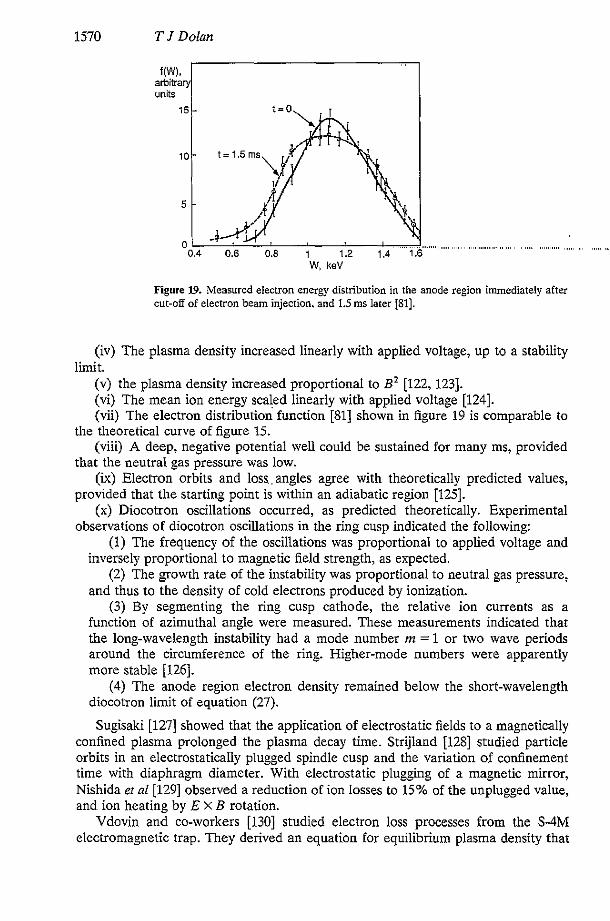
f(WL arbitra units
W, keV
Figure 19. Measured electron energy distlibution in the anode region immediately alter cut-off of electron beam injection. and 1.5 ms later [Sl].
(iv) The plasma density increased linearly with applied voltage, up to a stability
(v) the plasma density increased proportional to B 2 [122, 1231. (vi) The mean ion energy scaled linearly with applied voltage [124]. (vii) The electron distribution function [Sl] shown in figure 19 is comparable to
(viii) A deep, negative potential well could be sustained for many ms, provided
(ix) Electron orbits and loss,, angles agree with theoretically predicted values,
(x) Diocotron oscillations occurred, as predicted theoretically. Experimental
(1) The frequency of the oscillations was proportional to applied voltage and inversely proportional to magnetic field strength, as expected.
(2) The growth rate of the instability was proportional to neutral gas pressure, and thus to the density of cold electrons produced by ionization.
(3) By segmenting the ring cusp cathode, the relative ion currents as a function of azimuthal angle were measured. These measurements indicated that the long-wavelength instability had a mode number m = 1 or two wave periods around the circumference of the ring. Higher-mode numbers were apparently more stable [126].
(4) The anode region electron density remained below the short-wavelength diocotron limit of equation (27).
Sugisaki [127] showed that the application of electrostatic fields to a magnetically confined plasma prolonged the plasma decay time. Strijland 11281 studied particle orbits in an electrostatically plugged spindle cusp and the variation of confinement time with diaphragm diameter. With electrostatic plugging of a magnetic mirror, Nishida et nl[129] observed a reduction of ion losses to 15% of the unplugged value, and ion heating by E X B rotation.
Vdovin and co-workers [130] studied electron loss processes from the S-4M electromagnetic trap. They derived an equation for equilibrium plasma density that
limit.
the theoretical curve of figure 15.
that the neutral gas pressure was low.
provided that the starting point is within an adiabatic region [125].
observations of diocotron oscillations in the ring cusp indicated the following:

Magnetic electrostatic plasma confinement 1571
vaned with electron beam current, electron energy and neutral gas pressure in accord with experimental data. Plasma electron diffusion was dominated by scattering off gas molecules and molecular ions. They suggested that anomalous electron transport in the ring cusp region may be caused by a long-wavelength two-stream instability. The injected electrons had an anomalously fast loss rate in the S-4M electromagnetic trap, and neutral gas effects kept the plasma cold (a few eV temperature).
According to measurements by Komarov et al 11311 with a two-wavelength microwave interferometer in the Jupiter-1A spindle cusp device, the central density was an order of magnitude higher than the average density. Zalesskii et a1 [132] found that the the plasma accumulation rate with microwave heating was much faster than with electron beam injection, and about 50% of the microwave power was coupled to the plasma.
Stepanenko and Komarov [133] measured the Jupiter-1A electron and ion energy spectra during microwave heating with 10% power absorption, and deter- mined the electron energy confinement time to be about 0.9 ms. The dominant ion energy loss mechanism was charge exchange.
Electron and ion energy spectra were measured with gridded electrostatic energy analysers at the point cusps. The electron energy distribution is shown in figure 19. The ion energy spectra were measured with a drift mass spectrometer combined with an electrostatic ion-energy analyser. The distribution appeared to have two Maxwellian components. The higher-temperature component was believed to be caused by the initial formation of the potential well. The average energy of the ions increased linearly with applied voltage, {W) - 0.18+* [36].
Komarov and Stepanenko [134] measured the spatial variation of the total number of electrons N, leaving the ring cusp gap, and found a narrow distribution with width 6--p,, as shown in figure 20. At an electron energy of 0.55keV p. = 0.1 mm. The distribution was narrower at high plasma densities, indicating that electron losses along the magnetic field became important relative to cross-field diffusion losses. The model profile with w = p. is roughly consistent with the experimental data, but w = 2p, is used here in estimating future device parameters to avoid underestimating A+. Komarov and co-workers [135] also measured the distributions of electrons and ions in a point cusp gap, finding a narrow electron stream with radius <1 mm.
- n(z) n = 1.0 '.'N ,
0.8
0.6 \
0.4 '\ ',. ---___ --. .. '.. 0.2
0.0 0.0 0.1 0.2 0.3
2,"
Figure 20. Experimentally measured elecrron density distribution (full curve) in the ring cusp of the Jupiter-1A device at +,=6kV B=O.SZT, and model profiles n/n,= 1/[1+ ( Z ~ W ) ~ ] with w = p E (broken curve) and w = Zp, (dotted curve).

1572 T J Dolan
In the KEMP-I1 spindle cusp experiment Stansfield and colleagues [I361 measured n - 4 X 10” mY3, and electron energies -1 keV. Ionization of gas pro- longed the plasma density persistence after electron beam cut-off.
3.2. Jupiter-IM
The Jupiter-1M spindle cusp experiment at Kharkov [137] had pulsed magnetic point cusp fields S13 T (25 ms half-period), ring cusp fields S 4 T, electron injection voltages -4 kV, plugging voltages +A - 6 kV, electron beam injection current S 2 mA, neutral gass pressure 0.1-1 mPa and plasma volume 30 cm3. It attained plasma densities up to 10” m-3, with temperatures -100 eV and confinement times -1 ms. The short duration of the pulsed magnetic fields did not allow enough time for build-up of higher plasma densities. The plasma losses from the point cusps were less than from the ring cusp [138].
Komarov and colleagues [139] used gridded analysers to measure the energy distributions of electrons and ions emerging from the cusp gaps after removal of the plugging voltage. The mean ion energy observed under those conditions was about one-fifth of the plugging voltage. For a few microseconds after electrostatic plugging was removed, the remaining ions were accelerated to higher energies by the plasma potential [la]. The measured potential barrier in the ring cusp for ions +i -32; exceeded the calculated barrier -2T. The barrier height in the point cusp was practically zero, but most of the ion losses occurred through the ring cusp. Point cusp ion losses were probably retarted by the centrifugal and magnetic field gradient forces [141].
Azovskii and colleagues [142] found that the inner bounding surface of the plasma in the Jupiter-1M experiment has a radius r, = (2Rp,)In in the point cusp (where po is the electron Larmor radius in the point cusp), as predicted from flux mapping to the ring cusp. The density of plasma flowing out of the point cusp was two orders of magnitude lower than the central plasma density, and A+ = 0.5 kV was inferred from the shape of the ion energy distribution emerging from the point cusp [143].
Azovskii and co-workers [144] measured the plasma density in Jupiter-1M simultaneously by a microwave interferometer and by the integral of the ion loss current, and found that n = 1018m-3. The lifetimes of electrons injected from the gun were much shorter than the lifetimes of plasma electrons produced by ionization. The conlinement time of the bulk plasma was about a factor of five lower than classical, assuming that the electrons were produced by ionization. The injected fast electrons left quickly (-0.01 ms), perhaps due to a two-stream instability, and imparted only about 1-2% of their energy to the plasma. The electron current had 0.1-1 MHz modulations. Probe measurements showed that the electron density profile was not consistent with a theoretical probfile based on classical transport
Factors influencing the electron conlinement times included the magnetic field geometry, impurities in the plasma, ionization of neutral gas and electron mobility in the electric field. The effect of the centrifugal force on radial electron transport would be less significant in large devices. Since the electron mobility is related to the neutral gas density, its contribution was significant in small devices, but would be reduced in high-temperature plasmas, where most of the neutral gas becomes ionized 11461.
11451.

Magnetic electrostatic plasma confinement 1573
From ion energy distributions measured outside the point cusp and ring cusps of the Jupiter-1M device at ++. = 6 kV, Azovskii and co-workers [147] deduced the amount of potential sagging in the anode gaps, and found A+ (ring cusp) = 0.4 kV, A+ (point cusp) = 0.6 kV. These values correspond to uncompensated anode electron densities n, - 10'' m-3, while the central electron density n - 101'm-'. The electronic space charge in the anode gaps was partially compensated by ions flowing out the cusps. Although the ion potential barrier $+ was lower in the point cusp, the ion loss rate there was lower than in the ring cusp. From gridded analyser data they found that the ion energy distribution was nearly Maxwellian with 1; = 40-60 eV. 1; was slightly higher at the plasma edge, where the electric field was large [148].
Azovskii and colleagues [149] measured the electrostatic potential and electron temperature in Jupiter-1M. At the end of electron beam injection the potential sag. in the point cusp cathode A+ - 1 kV. The electron temperature reached 25 eV, then dropped rapidly after electron beam injection cut-off. Using an 8 keV Ari probe beam, they measured the energy spectra of Al+ions emerging from the ring cusp and deduced the time variation of the central plasma potential. When energetic electrons were injected into low-pressure hydrogen, the plasma potential (+i + A + ) initially was very large. As ionization built up the plasma density, the plasma potential'decreased to a plateau value on the order of 0.1+*. After the electron beam injection was turned off, the plasma density and potential decayed to zero in a few milliseconds [150].
3.3. Magnetic multiples
Nakamura er al 11511 observed enhancement of ion confinement in a multipole magnetic field by a negative electrostatic potential well produced by electron injection into the plasma. Hershkowitz et al[152] observed similar effects.
Lavrent'ev and colleagues [153. 1541 studied the plasma produced by injection of 100 mA of 1 keV electrons into a pulsed multipole trap. They measured n = lOI7 m-3, confinement time = 50 ps and 1; - 300 eV. Using the attenuation of a calcium ion beam during a 30 p s period of electron injection, they observed~ a rapid density build-up to 4 X lOI7 m-3, followed by a decay after electron beam cut-off. With probe measurements they found a uniform central plasma density dropping off steeply in the boundary magnetic field layer 11551. Lavrent'ev et al 11561 found that the plasma lifetime in a multipole electromagnetic trap depended very strongly on the magnetic field in the gaps, decreasing from 1.3ms to 0.1ms as the field was reduced from 0.3 T to 0.15 T.
Moir et a1 11571 proposed a toroidal quadrupole MEPC experiment using soft iron to enhance the magnetic field shape and to minimize the required coil currents.
Maffei er a1 [158] constructed a spherically convergent ion focus (SCIF) device based on Bussard's Polywell'" concept (a polyhedral set of point cusps), with planned values of 5 = 0.2T, + = 20 kV, I = 75 A from three electron guns and plasma production by electron cyclotron heating.
3.4. ATOLL
The ATOLL toroidal quadrupole magnetic cusp device is shown in figure 21. Typical parameter values are B, = 0.8 T, +A - 2 kV, p = 0.2-0.5 mPa hydrogen, impurity fraction = 1-2% (dominant mass = 28), n = 3 X lOI7 m-3, = 100 eV and

1574 T J Dolan
ATOLL
Figure 2l. The ATOLL toroidal quadrupole cusp device [MO].
average ion energy = 100 eV. Ioffe et nl[159] checked the alignment of the magnetic field with the anodes by observing the flow of electrons from an electron gun placed in the plasma region. The alignment accuracy was better than 0.2 mm. Diagnostics included an 8 mm microwave interferometer, currents drawn by electrodes, a charged particle energy analyser, Langmuir probes (including a tiny probe sus- pended by a 12 p m tungsten fibre), a charge exchange neutral atom energy analyser, a pulsed vacuum guage and a partial pressure analyser.
In one mode of operation the plasma was sustained by electron injection from a gun plus secondary emission at the reflecting cathodes. This mode resembled a Penning discharge with the end walls outside the cusps.
In another mode of operation Ioffe and co-workers [160] minimized the plasma impurity content by careful wall preparation and by the use of very pure hydrogen. Ionization of neutral gas made up for particle losses, and the electrons were heated by the intense electric field in the boundary layer. At high magnetic fields and low pressure the discharge could become self-sustaining without electron injection or secondary emission from the cathodes. This regime had similar plasma parameters, but less noise, better ion confinement and higher T, than the lint regime. This ‘emission-free’ discharge was estinguished by adding 5,% ,of an impurity, such as nitrogen. Impurities increased radiation losses and diffusion rates, and reduced the potential well depth.
The plasma potential increased’linearly with magnetic field and had a nearly parabolic radial distribution. Ions produced by ionization at the edge were heated as they fell into the potential well, and the average ion energy increased with increasing magnetic field. ‘From the plasma confinement time it was inferred that the potential barrier +i impeding ion loss through the cusps was very small. Ioffe and colleagues [161] found that the electrostatic potential in the cusp gaps was equal to the potential at the plasma centre, to within experimental accuracy (10%). The hypothesis of a narrow ‘neutral corridor’ through the cusps with no confining potential barrier (+i = 0) was also consistent with the measured variation of plasma potential with magnetic field.
The electron potential barrier +e - lOc, so electron losses were predominantly by cross-field diffusion. From the ionization rate Ioffe and co-workers [162, 1631 inferred a plasma confinement time of 0.18ms. This was close to the theoretical

Magnetic electrostatic plasma confinement 1575
conhement t h e , based on the ion acoustic instability, of 0.12 ms, and much shorter than the classical confinement time of 50-150 ms. Similarly, the measured electron density profile was close to that predicted above for the ion acoustic instability, with a gradient scale length on the order of the ion sound Larmor radius, and far from the profile based on classical diffusion. Piterskii and co-workers [164,165] observed oscillations at 40-80 MHz propagating in the electron diamagnetic drift direction at about 105ms-', which appeared to be consistent with ion acoustic instability theory. According to Lavrent'ev [166] the cross-field transport resulting from the observed profiles and oscillations in ATOLL should be inwards.
Later measurements revealed that three instabilities were occurring simul- taneously in ATOLL diocotron oscillations in the cusp gaps, a long-wavelength ion acoustic instability in the plasma interior abd a lower hybrid drift instability at the plasma edge.
Piterskii et a1 [167] observed diocotron oscillations in^ the cusp gaps at frequencies of 40-70 MHz, with wavelengths of 1-2 cm and peak amplitudes -100 V. The wave phase velocity was somewhat lower than the electron E X B drift velocity in the anode gaps, by a factor of 1.5-2; but this difference could be partly due to simplifying assumptions used in the analysis, such as the shapes of the electron density distribution and electric field distribution in the anode gaps. The theoretical maximum growth rate of the diocotron oscillations occurs at A - 16a, which is within the range of wavelengths observed. The instability became stronger with increasing plasma potential and decreasing magnetic field, as expected for diocotron oscilla- tions. In the central plasma the amplitude of the diocotron oscillations decayed with distance from the anode^ gaps with a scale length of about 5 cm, as expected theoretically.
Piterskii and co-workers [168, 1691 found that the lower hybrid drift instability is dominant in the boundary region where the density is low. The theoretical values of most unstable wavelength (1 cm), frequency (12MHz) and phase velocity (1.2 X 10⁵m SKI) are consistent with experimental data. This instability causes anomalous electron transport, flattening the electron density profile until the density gradient scale length (n/Vfl) exceeds the local ion Larmor radius pi. Thus, the confinement times in ATOLL were much shorter than classical confinement times, and the anomalous transport was well understood in terms of the lower hybrid drift and long-wavelength ion acoustic instabilities.
3.5. Jupiter-2M
The proposed Jupiter-2 experiment [170] was to be a linear set of ring cusps with E , = 5 T (point cusps), $A = 25 kV, V = 0.5 m3, n > lox9 m-3, I; - 1 keV and zE - 100ms. Due to financial limitations, a one-third scale model of Jupiter 2, called Jupiter-2M [171] has been built first (figure 22), with a primary goal of studying electron transport.
The Jupiter-2M device has seven ring cusps with R = 0.215 m in the central region flanked by one small ring cusp and point cusp at each end. The axial length between the point cusps is 1.30m. The coils are pulsed from a capacitor bank and reach peak fields in about 33 ms. The ,maximum attainable ring cusp and point cusp magnetic fields are about 1.94 ~ . d 3.88 T. respectively, but lower fields have been used in experiments. The shape of the vacuum magnetic field is illustrated in figure 23 [171].

1576 T J D o h
field
Figure 22. The Jupiter-2M device (left) and electrode region detail (right) [171].
The plugging electrode positions were adjusted by screws until comb probes at three azimuthal locations 120" apart showed no asymmetry of the electron loss currents emer,$ng from the cusps. The total plasma volume is 50 1, and the volume of the uniform central region is 16 1.
The classical electron diffusional loss rate is [172,173]
I d i s = [Da(1 + OS+p/T,) +Dei]FnORZ electronsls (55) where D. is the electron diffusion coefficient due to collisions with neutral atoms, +p = 4i + A + , Dei is the electron diffusion coefficient due to collisions with ions, no is the central electron density, Go is the central electron temperature, and F is the geometrical factor having dimensions of reciprocal length. The +p term represents electron mobility in the strong edge electric Eeld. The electron confinement time is
zdiff = NJIdiff = 1.11zR3no/Iditr (56) where Ne is the total number of electrons in the plasma. For the geometry of the Jupiter-2M experiment F = 900/cm.
I, cm
Figure 23. Vacuum magnetic field lines in the Jupiter-2M device [171].

Magnetic electrostatic plasma confinement 1577
0 0.2 0.4 0.6~ 0.8 1.0
n,, 10'' m.3 Figure 24. Ratio of experimental to theoretical electron loss currents, as a function of plasma density. B = 0.3751 (+), 0.5 T (e), 0.625 T (*) [174].
Preliminary low-field operation at B -0ST (ring cusp) with a 1.3kV, 0.12A electron beam injection into 2 X Torr (H2) produced a plasma with n = 5 x lo1' m-3, 7'' = 13 eV. z, > 2 ms. With +A - 2 kV, the plasma potential was about -3oOV relative to the grounded chamber walls. About 80% of the injected electron beam energy appeared in the plasma. Although the point cusp anode diameters were 25 mm, the ion loss through the point cusps was only 6% of the total ion loss rate.
High-frequency oscillations were not observed in Jupiter-2M. The large uniform central plasma may serve as a buffer to damp out surface oscillations. Vdovin et a1 [174] found that the ratio of experimental electron loss current to theoretical loss current decreases with increasing plasma density, as shown in figure 24. At higher plasma densities, the experimental loss rate was about twice the classical value. The measured ion loss rate corresponds to an ion potential barrier +JT - 4.
Auxiliary electrodes were used to suppress secondary electron emission from the plugging cathodes. Diaphragms limiting the plasma boundary in the point cusps and between the ring cusps served two functions: (i) to reduce particle flow onto the anodes, where gas emission stimulated by particle bombardment would tend to fill the gap with cold plasma, and (ii) to study the influence of the diaphragm size on plasma transport. Ring diaphragms with diameters of 21,24 and 28 cm corresponded to ring cusp diffusion layer widths a = 0.9, 1.6 and 2.0 mm.
The theoretical electron density profile depends little on the temperature profile. The electron density profile is flat in the centre and falls nearly linearly to zero near the plasma edge. There is a uniform central plasma with radius -5 cm and length -80 cm. As the diffusion layer width a is increased from 0.9 to 2.0 mm. the electron confinement improves, but ion confinement degrades, due to the increase of A+. There is also an increased probability of arcing with large gap widths, due to anode bombardment and outgassing. At the optimum width aOpf = 1.6mm the maximum plasma density n = lo1* mW3 is attained. The electron confinement time deduced from the total number of electrons in the plasma divided by the total electron diffusion loss current is z, = 3 ms. Future plans are to increase the magnetic field to 1-2T, and to inject hot plasma with a plasma gun.

1578 T J Dolan
3.6. Impurities
Impurity effects in MEPC devices have been studied very little. Lavrent'ev [94] showed theitheoretical effect of increasing Z,, on the energy confinement time. However, nobody has computed impurity source terms, transport and build-up.
A continuous impurity accumulation was observed in the ATOLL device during the injection pulse. A typical impurity level was 1-2% with the dominant species at mass 28 [159]. The addition of a few per cent impurity extinguished the 'emission free' regime of ATOLL [160]. There have been almost no studies of impurity profiles, impurity transport, radiative power loss or methods of impurity removal from an MEPC plasma. Impurity studies need greater emphasis in the future. As Gormezano [39] stated: 'Any electrostatic system will constitute a very good containment system for heavy impurities. The presence of electrodes in environ- ments with high electric fields and high particle fluxes may constitute a very large source of impurities. This might ultimately be the greatest problem'.
3.7. Comparison of experiments
Key parameters of various MEPC experiments are summarized in table 2. In some cases the effective temperature is taken to be two-thirds of the average particle energy. The early'experiments at Kharkov (S-1, S-3, S-3M and S-4M), Quebec, Missouri and Jutphaas were small spindle cusp plasmas with weak fields, and neutral gas effects were dominant. Such experiments are of less interest now, but they served to demonstrate the principles of MEPC. The multiple point cusp SCIF device was shut down by budget cuts before reaching its projected operating parameters, but it may be restarted at another laboratory.
The. Jupiter-1A device achieved good ion and electron temperatures (0.4-, 1.5 keV). It also demonstrated the effectiveness of electron cyclotron heating, although at low powers. The Jupiter-1M experiment was not able to fully utilize its high magnetic fields, because the duration of the peak field was too short to permit accumulation of high plasma density. Due to their low ratios of plasma volume to surface area V / S R 5 0.03, spindle cusps are not worthwhile considering for future experiments.
The linear multipole devices demonstrated conlinement in that geometry and validated theoretical predictions of critical loss angles. Due to end losses, these devices did not achieve high plasma pressures.
The ATOLL totoridal quadrupole was carefully built and operated, but the electron energy transport was anomalous. Detailed studies related the anomalous transport to the lower hydrid drift instability (plasma edge) and to the ion acoustic instability (plasma interior). ATOLL was shut down in the 1980s.
The Jupiter-2M experiment has attained the most promising results. Its demon- stration of near-classical transport is stimulating interest in MEPC research.
3.7.1. Density, temperature and confinement time scalings. The plasma density in spindle cusps was typically 10"-101* m-3. The attainment of higher plasma density has been a major concern for the reactor prospects of MEPC devices. The plasma density appears to scale proportional to B2 [122], provided that the magnetic field duration is long enough for density accumulation. The central plasma density n is found to he significantly higher than the electron density n, in the anode region, but

Magnetic electrostatic plasma confinement
" N m i 0 P'D 11 P
1579
1580 T J Dolan
more definitive measurements of the ratio n,ln are needed at high plasma temperatures.
The measured electron energy distributions resemble shifted Maxwellians, as expected. Computer models indicate that, 3 neutral gas effects are not dominant, the plasma temperatures scale proportional to the applied voltage. Measured ion temperatures have scaled linearly with +& For the plasma density and temperature in MEPC devices, we assume the following scaling
n=B2 (57)
T, = = 0.05q5,. (58) The scalings were used to estimate the hypothetical reactor parameters in tables 1 and 2. That the temperatures in Jupiter-2M were below this assumed scaling may be due to the short duration of the peak magnetic field, the weak heating power and neutral gas effects.
For small spindle cusp devices the confinement times have been r-0.1-1 ms. Little distinction has been made experimentally between particle confinement and energy confinement. For ring cusps the conhement time is assumed to scale roughly in accordance with equation (40)
zdie = 0.09TeiaR/pbp,. (40) This equation predicts z d i p 0.8 ms for Jupiter-2M parameters of table 2. The experimentally measured co&nement time was 2-3 ms. (If the central electron temperature were higher than d e 15 eV reported from a Langmuir probe under the magnet coils, then the theroretical zdin would be longer.) A more precise computation specific to the Jupiter-2M geometry [173] predicts classical confinement times about twice the measured value.
3.7.2. Dimensionless parameters. Three dimensionless parameter ratios are listed in table 2: alp,, pc, and u.z/R. The alp, represents the number of electron Larmor radii within one-half of the ring cusp anode gap. In MEPC experiments this number has ranged from 5 to 100, and for a reactor it would probably be in the order of 20-30. The optimum anode gap width is of the order of 1.5-2 mm, and the electron Larmor radius is fixed by the magnetic field and electron temperature in a reactor to values of the order of 30-100 pm.-
The second dimensionless parameter is the ratio of average plasma pressure to the peak magnetic field pressure at the coil
P.-2p0nk(T. + QIBZ (59) where B, is the peak magnetic field at the coil = B,. (In magnetic confinement fusion it is more common to define beta relative to the vacuum magnetic field at the plasma centre, but that central magnetic field is zero in magnetic cusps, which would yield an infinite value of beta.) The values of pc in past MEPC experiments have been very low, of the order of 0.001 to 0.1%. Using the density and temperature scalings of equations (57) and (58) results in p. = 4.5% for d e hypothetical reactor of table 2. For comparison, the estimated value for the ITER tokamak (Troyon coefficient g=3,1=24MA, minorradius=3m, B =6T,BC=13T) isp.=0.85%.
The third dimensionless parameter in table 2 is u.zlR, which is the ratio of the confinement time to the approximate electron transit time through the plasma.

Magnetic electrostatic plasma confinement 1581
Present experiments attajn confinement values of about lo4 transit times. Without effective plugging, the plasma would only be confined for tens of transit times.
This number of transit times is relevant to a mode of free plasma flow out cusp gaps. It is less relevant to MEPC devices, because ions are confined electrostatically, and their confinement times are roughly equal to the electron cross-field diffusion time. Nevertheless, it is instructive to show that, if the ions were freely flowing out cusp gaps. those gaps would be very narrow. According to the free-flow model, the ion confinement time is
z = r;L,/uRS. (6) For Jupiter-2M, R = 0.22 m, rp ;- 0.1 m, L1 = 0.105 m, U = 7.6 X lo4 m s-', and z = 3ms. Using this equation we estimate the effective cusp gap half-width 6;- 2.1 X m, it is seen that 6 = pa. If free ion flow were occurring, it would be through a very narrow gap.
3.7.3. Anomalous transport. The diocotron instability in the ring cusp regions is believed to play a benficial role by removing anode-trapped cold electrons, which tend to screen out the anode potential, but other instabilities have deleterious effects. The ATOLL toroidal quadrupole cusp experiemnt had anomalous transport (hundreds of times faster than classical) in all operating regimes, associated with the long-wavelength ion acoustic instability and the lower hybrid drift instability. The Jupiter-2M multiple ring cusp experiment, however, has demonstrated nearly classical electron transport. So far, the reason for the difference is not understood. There are several hypotheses, as follows:
(i) In Jupiter-2M directed electron injection from thermoelectric cathodes was used. According to Lavrent'ev [l], electron injection in ATOLL by secondary emission from the cathodes introduced electrons into the diffusional layer (rather than into the central Brillouin region), which could foster the two-stream instability. The rate of electron production was two orders of magnitude greater than the electron loss rate by classical diffusion, so classical diffusion could not accommodate the required outRow rate of spent electrons from the trap.
(ii) ATOLL has two-dimensional curvature and only toroidal symmetry in the anode regions, while Jupiter-2M has one-dimensional curvature and (since h >>a) approximately two degrees of symmetry. This lack of symmetry in ATOLL might be more conducive to growth of the harmful instabilities, such as the lower hybrid drift waves; or it might somehow tend to^ reduce the beneficial effects of diocotron oscillations on cold electrons within the anodes.
(iii) The large volume of field-free plasma in Jupiter-2M may serve to damp the growth of instabilities.
More study will be required to falsify or confirm these hypotheses.
3.7.4. Assessment. MEPC experiments typically have had small radii R - 10-20 cm and plasma volume < 11, except for Jupiter-2M (50 1) and the SCIF device. The anode gap half-width ranges from 1 to 2mm. A larger gap could permit excessive voltage sag A+, and a smaller gap would decrease the electron diffusion loss time. The magnetic fields have generally been below lT, except for a few pulsed experiments. The applied voltage has been below 10 kV.
Many excellent measurements have been performed in MEPC devices. Detailed
m. Since the electron Larmor radius pa = 2.2 X

1582 T J Dolan
probe measurements have shown that the electron density profile in the ring cusp anode has a half-width about one Larmor radius. The electrostatic potential profile has been mapped out with pulsed ion beam transmission measurements and gridded energy analysers. A deep negative potential well has been sustained for many milliseconds. The electron velocity distribution resembles a shifted Maxwellian, as expected. These measurements verify the basic theory of MEPC.
The scalings of density, temperature and cordinement time have been established within the current ranges of parameters. The conlinement in some experiments is nearly classical, when neutral gas effects are taken into account. The diocotron oscillations in the ring cusps have been thoroughly studied and are well understood. The plasma waves associated with anomalous transport in ATOLL have been correlated with theoretical predictions.
Why some devices have anomalous transport and others do not is not yet understood. More measurements are needed of the density and temperature profiles, impurity distribution and transport, neutral gas distribution, radiation losses and heat propagation. Two-dimensional computer simulations are needed to provide a link between analytic theory and experimental data.
A common thread of deficiencies links almost all the past MEPC experiments: either weak or short-duration magnetic fields; relatively low voltages ( 4 0 kV); weak plasma heating; incomplete diagnostics; inadequate computer modelliig. These deficiencies have been caused by low budgets, not by failures of the experimenters.
Table 3 compares the parameters of Jupiter-2M with the proposed Jupiter-2 and Jupiter-T devices. If successful, Jupiter-T could demonstrate the attainment of thermonuclear parameters in a modest-sized device.
4. Reactor concepts
4.1. Reactor design studies
Various cusp geometries suitable for electrostatic plugging were illustrated in figure 8. Mirror geometries, such as a yin-yang field, are also possible for electrostatic plugging, but the plasma volume inside the anode-bounded flux surface is smaller than for cusp systems.
Table 3. comparison of Jupiter-2M, Jupiter-2, and Jupiter-T experiments 11741,
Parameter Jupiter-2M Jupiter-2 Jupiter-T
Ring cusp radius, R (m) Length between ends, L (m) Ring cusp magnetic field, B, (T) Point cusp magnetic field, 5, (T) Applied voltage, (kV) Electron injection current, I, (A) Plasma density, n (mm3) Ion temperature, T (keV) Plasma volume, V (m3) Electron d ~ s i o n current, I,;, (A) Electron lifetime, (s)
0.215 1.4 0.5 1
0.2
0.03 0.05 1.6 0.W
0.8 x 10'8
0.67 3.9 2.5 5
25 5
1 0.5
14 036
3 x 10¹⁹
1.4 6.4 4.0 8
100 30 160 10 4
120 1.3

Magnetic electrostatic plasma confinement 1583
Laurent'ev [175] considered several reactor geometries for MEPC reactors: a sphere, a cylinder and a t o m . They would typically operate at B, = 7 T, +a = 200 kV, n - lo'' ' k - 30 keV, V - 800 m3 and power density -4 MW m-3. They would provide intense sources of neutrons, which could be used for production of tritum or plutonium.
Pastukhov and Yushmanov [176. 1771 estimated the power gain of an MEPC reactor. At each value of applied potential +A there is a plasma temperature that maximizes Q. The optimum gap width makes A+/+* = 0.25, When the gap is wider, A+ becomes large, reducing the plugging potentials and +i. When the gap is narrower, electron diffusion losses are too great. At the optimum gap width, the ratio of fusion power to input power for a ring cusp plasma reduces to
Q = 10-s+',B,V/S(l + in,ln,)'" (60) where +A is in kV and n, is the trapped electron density in the anode region, Assuming nJn, 0.3 and V / S R = 0.3 in the example case of table 1, it is found that Q = 10. This analysis did not include energy losses due to neutral gas and impurities, or the beneficial effect of the alpha-particle emission current helping to reduce the required cathode current. Alternatively, using the parameters of table I with ZeB= 3 in equations (4D1) and (3F14) of [44], we find Q = 13.
A spherical cusp, shown in figure 8, would be advantageous from a physics standpoint [178, 1791. The sphere has the best surface-to-volume ratio, and the spherical electrode arrangement might provide some spherical focusing of charged particles. If effective, such focusing could increase the central plasma density and decrease the required magnetic field in the cusps. However, particle scattering by waves and by Coulomb collisions and reflections off the scalloped boundary would tend to diminish the degree of focusing. It would be difficult to align the electrodes with the magnetic field lines in a spherical reactor.
A torodial hexapole reactor design had B, = 8 T, +A = 300 kV, n = IO'' m-3, T = 17 keV and a neutron wall loading = 1.6 M W m-' [84]. The direct capital costs estimated for this reactor were comparable to those for tokamak and tandem mirror reactors [180].
From the results with Jupiter-ZM, it appears that ion losses from the point cusps are not a serious problem, so a linear set of ring cusps would be feasible for a reactor. Such a reactor would be superior to either the spherical cusp or toroidal hexapole cusp, because of its simplicity, lower structural mass and easier main- tenance. A linear MEPC reactor, as illustrated in figure 25, could have the parameters of table 1, with Q = 10. DT fusion power density = 3 MW m-3, neutron
Figure 25. One end of a linear MEPC reactor.

1584 T J Dolan
High Voltage Input
Figure 26. Radiation collimator and voltage divider for high-voltage electrodes.
wall loading = 3.6 MWm-’, L = 50 m, and total fusion power = 4.2 GW. Radiation collimators and voltage dividers would be used to prevent high voltage breakdown, as illustrated in figure 26.
4.2. Applications
Besides power production, there are other potential applications for MEPC devices. Their good confinement of high-2 ions would make them well suited for stripping and confining heavy ions for accelerators, as suggested by S t k [181,182].
Nadler et a1 [183] have suggested that small inertial-electrostatic confinement (IEC) devices operating jn the glow discharge mode at 30-50kV could become useful low-cost neutron sources producing >lo6 DD neutronds for a variety of applications, including detector calibration, diagnostics and training. By increasing the voltage, current and size, and using DT fuel, yields of lO”neutrons/s might be attainable. Such neutron sources could be stronger than 2nCf sources (2.6 year half-life), and they would be simpler and cheaper than accelerator-based neutron sources.
Miley el a1 11841 found that IEC device operation in the ‘star’ discharge mode maximizes the effective grid transmission factor for ions. An IEC device using D-3He fuel could generate 14.7 MeV protons for production of positron-emitting radioisotropes that are useful for positron emission tomography facilities. Miley et al [U51 proposed the use of high-voltage collectors in a ‘venetian blind’ configuration to convert the D-3He reaction product kinetic energy directly into electricity.
Miley et a1 [186] studied hydrogen production by radiolysis of water with 14.7MeV protons from an IEC device. The 3.6MeV alpha energy would be converted directly into electricity. The protons would pass through a thin chamber wall and interact with steam flowing through the cell, splitting about 13 water molecules per 100 eV of energy deposited by the protons. The steam would pass through a turbine to generate electricity, and then the hydrogen would be removed from the condensate. The overall system efficiency could be about 50%.
Bussard 1187 suggested the use of an electron-beam-heated propellant thruster powered by an electrostatic plasma device for space propulsion. Miley er a1 [188] suggested the use of IEC engines with venetian blind energy convertors to power five 68-N arcjetlmagnetoplasmadynamic thrusters with a specific impulse of 3000 s.

Magnetic electrostatic plasma confinement 1585
In pulsed operation, an IEC reactor with R = 5.25 m and mass = 5 t could deliver 12 MW of power to the thruster [189]. Bussard [190] proposed the use of a Polywell keactor for space propulsion.
An MEPC plasma with T = 10-20 keV would be a good target for neutral beam injection at U: = 150 keV with a beam ion fusion probability- lo-’ [191]. Such a device could serve as a powerful neutron source for isotope production, medical therapy or materials testing.
5. Issues of MEPC
Although some recent confinement results appear promising, there are still many issues to be resolved before MEPC devices can become fusion reactors, as discussed below.
5.1. Self-shielding of applied potentials
The potential drop in point cusp anodes is very large, but point cusp ion losses can be kept low by the centrifugal and magnetic field gradient forces, as demonstrated in Jupiter-2M. At B < 6 T, values of n, < 1.5 x 10’’ m-3 are required to keep A+ S 100 kV in the ring cusps. The potential sagging in the anode means that high applied voltages are needed to ensure substantial +e and &.
5.2. Neutral gas effects
Neural gas increases cross field transport rates and promotes high-voltage break- down. The plasma tends to act as a vacuum pump, and in future large MEPC devices the neutral gas effects should be less dominant than in small spindle cusps. Nevertheless, there will always be substantial recycling of hydrogen isotopes and helium off the walls, so shields should be used to prevent excessive ftow of neutral gas to the anode regions, where build-up of cold trapped electrons would increase A+. High-speed vacuum pumping will be required in the electrode region.
5.3. Electrodes
Optimized plasma confinement by careful alginment of each anode was demon- strated in Jupiter-2M. Radiation shields and voltage dividers will be needed to sustain voltages +A > 200 kV. To avoid warping. the anodes should be actively cooled and made from materials with low thermal expansion. Although high-voltage holding in radiation fields must still be demonstrated in MEPC devices, the PSP-2 rotating plasma experiment [192] has demonstrated the sustainment of 400 kV applied voltage with hot plasma present.
5.4. Transport
The reason why Jupiter-2M had good confinement and ATOLL had anomalous transport is not yet understood. Transport in MEPC devices has been studied much less than transport in tokamaks and tandem mirrors, so this lack of understanding is not surprising. Several hypotheses have been suggested the effect of the electron

1586 T J Dolan
injection method, the effects of curvature and symmetry, and the effect of a large volume of field-free plasma. The extension of the good confinement to larger devices remains to be tested experimentally. A more powerful experiment is being designed to test the scaling relations at higher values of plasma density, temperature and confinement time.
5.5. Power gain ratio
The estimated power gain ratio for an MEPC reactor with nearly classical fuel ion confinement (but no alpha-particle confinement), +A = 400 kV, B, = 6 T, R = 4 m, is Q = 10. The power gain ratio could be increased by the following means: increasing the applied voltage: increasing the magnetic field; increasing the plasma volume; improving alpha energy confinement.
One means of improving alpha confinement would be to add a modest toroidal field to a toroidal multipole device (similar to the Tormac configuration [193]). The toroidal field would help to confine alpha-particle energy, facilitating ignition, and the resultant magnetic shear might help to stabilize the lower hybrid drift instability in the plasma edge layer 11941. Another possibility might be the addition of a weak longitudinal magnetic field underneath the surface cusp field of a linear set of ring cusps.
5.6. Plasma impurities
Since alpha particles are poorly confined, helium ash accumulation could be slower than in tokamaks. However, sputtered wall atoms which penetrate into the plasma core would he well confined. Impurity ion accumulation would dilute the fuel density, cool the electrons by radiation losses and diminish the potential well depth. One means for impurity removal might he to use the centrifugal force of their rotation in a weak longitudinal field to expand their orbits so that a pumped limiter could extract them. Another possibility would be to expand the point cusp hole at one end of a linear reactor and to flow in fresh fuel from the other end, so that the weak pressure gradient gradually moved impurities to the hole. If effective impurity removal methods could not be found, then periodic shutdowns might be required for impurity removal, followed by restarts with fresh fuel.
5.7. Materials issues
The wall activation, afterheat, accidental release of radioactivity and waste disposal issues of MEPC reactors would be comparable to those of tokamaks and other magnetic confinement devices. The reactor design should provide for 'rapid replacement of damaged walls and electrodes. The desirable first wall neutron power flux would probably be about 2-5 MW m-*. Higher values could cause heat removal and wall lifetime problems, and lower values would raise the cost of electricity. The anodes should be partially shielded from radiation, and the electrodes and walls must be actively cooled. Low-activation materials, such as purified vanadium- chromium alloys and Sic, should be used if feasible.
One possible materials combination for an MEPC reactor is vanadium alloy

Magnetic electrostatic plasma confinement 1587
structure with a circulating Flibe (LiF-BeF,) molten salt blanket and coolant. Use of the molten salt would avoid the reliability problems of high-pressure coolants and the fire hazard of lithium. A small amount of lithium could be used to cool first-wall hot spots, if needed. The irradiated vanadium alloy could be cooled for tens of years, then remelted to remove the volatile long-lived isotopes (mostly "Ar) and recycled [195]. With careful choice of materials, an MEPC reactor would not require active safety systems to prevent prompt off-site fatalities in the event of a serious accident.
6. Conclusions and recommendations
(i) Purely electrostatic plasma confinement with spatial and temporal focusing may be wroth re-examination (section 1.1.4).
(ii) Due to magnetic reflection and electrostatic acceleration effects, the central plasma density in an MEPC device may be an order of magnitude higher than the electron density in the ring cusp region. Cold electrons from ionization of neutral gas tend to screen out the anode potential, but they are probably removed from ring cusps by diocotron oscillations (sections 2.5, 2.6).
(iii) Although anomalous transport was observed in the ATOLL toroidal quadrupole device, the plasma loss rate in the Jupiter-2M linear ring cusp experiment was only about twice the classical rate, improving at higher density. The reason for the good stability of the Jupiter-2M plasma is not yet understood, but might be related to its method of electron injection, its better symmetry, or its large volume of uniform field-free plasma (section 3.7.3).
(iv) Based on present experimental results, a linear set of ring cusps appears to be the most favourable configuration for an MEPC reactor.
(v) Several decades of small, cheap, pulsed experiments have demonstrated the basic principles of MEPC, but these experiments have been marred by weak or pulsed magnetic fields. low voltages, weak plasma heating, incomplete diagnostics and inadequate computer modelling (section 3.7.4.). Further progress depends upon increasing R, B and in a steady-state device, so that n, T and z, can approach the thermonuclear regime. A new experiment is needed to demonstrate the attainment of interesting parameters (n > 3 X 10¹⁹ T > 5 keV) in a steady-state device with intermediate size (R = 2 m, L = 10 m) and reasonable applied fields (B = 5 T, +A = 100 kV).
(vi) For an MEPC reactor with near-classical transport, values of Q - 10 are predicted at voltages +A = 400 kV (section 4.1). Q could be enhanced by partial confinement of alpha particles.
(vii) The Polywell'" and modified Penning trap concepts are just beginning to be studied. They need more research to determine the attainable degree of focusing and to explore related concepts that may lead to attractive fusion reactors (sections
(viii) Radiation shields and voltage dividers should be used to prevent high- voltage breakdown. Voltage holding at 400 kV has been demonstrated in a magnetic mirror geometry by the PSP-'2 rotating plasma experiment (section 5.3).
(ix) MEPC devices may find applications as (section 4.2): electrical power plants; heavy ion sources; neutron sources for materials testing, medical therapy and isotope production.
2.10, 211).

1588 T J Dolan
(x) The main issues of concem for MEPC reactor development are: electron transport, plasma punty and electrode alignment and voltage holding. Future research should concentrate on resolving these issues.
Acknowledgments
This review is dedicated to 0 A Lavrent’ev, who has led this field of research steadily for four decades, in spite of many dif6culties. R W Bussard provided information on the Polywell“ concept, and L Tumer, D C Barnes and R A Nebel provided information on the modified Penning trap research. This work was supported by the US Department of Energy, Office of Fusion Energy, under DOE Idaho Field Office Contract number DE-AC07-76ID01570.
References
[l] Lavrent‘ev 0 A 1992 unpublished letter to T J Dolan 17 October 1992 [2] Famsworth P J 1966 US Parenr 3258402 [3] Lavrent’ev 0 A 1963 Ukrain. Fiz. Zh. 8 440-5 [4] Budker G I 1961 Plasma Physics and the Problem of Conrrolled Thermonuclear Reacriom I
[5] Lavlent’ev 0 A 1968 Investigation of an electromagnetic trap Magnitnye Louurhki Vypusk 3 (Kiev:
[6] Hirsch R L 1970 US Parent 3 530 036 [7] Dolan T J, Verdeyen J T, Cherrington B E and Meeker D J 1970 Electrostatic-Inertial Plasma
[8] Lavrent’ev 0 A, Sidorkin V A, Zaitsev B V, Goncharenko V P and Ovcharenko L I 1972 Ukmin.
[9] Lavrent’ev 0 A, Sidorkin V A, Zaitsev B V and Azovskii Yu S 1972 Ukmin. Fiz. Zh. 46 1282-4 [IO] Azovskii Yu S, Zaitsev B V, Lavlent’ev 0 A, Sappa N N and Sidorkin V A 1976 Generation and
focusing of ions from a Source with distributed parameters Report 76-9 (Institute of Physics and Technology, Ukrainian Academy of Sciences, Kharkov)
(Elmsford, Ny: Pergamon) pp 295-301
Naukova Dumka) pp 77-147 (translation: AEGTR-7002 (Rev))
Confinement US Air Force Ofice bf Scienr$c Research Repon AFOSR-70-1656TR
Fir. Zh. 42 143-6
[ l l ] Lavrent’ev 0 A, Sidorkin V A, Zaitsev B V and Azovskii Yu S 1976 Zh. Tekh. Fiz. 46 1282-4 [I21 Lavrent‘ev 0 A, Sidorkin V A, Zaitsev B V and Sappa N N 1973 Investigatibn of gas discharge in a
spherical diode Proc. XIth Inr. Con$ on Phenomena in Ionized Gases (Pmque) (Prague: Czechoslovak Academy of Science)
[13] Hirsch R L 1968 Phys. Fluidr 11 2486-90 [14] Elmore W C, Tuck J Land Watson K M 1959 Phys. fluidr 2 239-46 [I51 Hockney R W 1968 3. Appl. Phys. 39 4166-70 [16] Barnes C 1973 Computer simulation of electrostatic inertial confinement Stanford University Report
1171 Porter G D and Klevans E H 1971 Phys. Fluids 14 428-34 1181 Hirsch R L 1967 3. Appl. Phys. 38 4522-34 [I91 Hu K M and Klevans E H 1974 Phys. Fluids 17 227-31 PO] Cherrington B E, Verdeyen J T and Swanson D A 1975 Ann. NY Acad. Sci 251 139-51 Fl] Swanson D A, Cherrington B E and Verdeyen J T 1973 Phys. Fluids 16 1939-45 [22] Swanson D A, Cherrington B E and Verdeyen J T 1973 Appl. Phys. Lett. 23 125-6 [U] Verdeyen J T, Cherrington B E, Swanson D A and Meeker D J 1975 Ann. NY Acad. Sci 251
[24] Meeker D J, Verdeyen J T and Cherrington B E 1973 J. Appl. Phys. 44 5347-55 [25] Imel G 1973 PhD Thesis Pennsylvania State University [26] Black W M and Klevans E H 1974 J. Appl. Phys. 45 2502-11 [27] Klevans E H 1975 A n n NY Acad. Sci. 251 190-212
AD-763826
126-38

Magnetic electrostatic plasma confinement 1589
[28] Black W M and Robinson J W 1974 J. Appl. Phys. 45 2497-501 [29] Gardner A L, Hatch D M, Chan A I Y and Evans R P 1975 Ann. NYAcad. Sci. 251 179-89 [30] Baxter D C and Stewart G W 1982 J. Appl. Phys. 53 4597-601 [31] Pctcrson J M and Oleson N L 1992 Phys. Fluids B 4 888-901 [32] Nadler J H, Gu Y B and Miley G H 1992 Rev. Sci. Instrum. 63 4810-12 [33] Miley G H, Nadler J, Hochberg T, Gu Y, Barnouin 0 and Lovberg J 1991 Fusion Technol. 19
[34] Hirsch R L and Meeks G A 1970 US Porenr 3530497 [35l Dolan T J, Verdeyen J T, Meeker D 3 and Cherrington B E 1972 J. Appl. Phys. 43 1590-600 [36] Lavrent’ev 0 A 1975 Ann. NY Acad Sci. 251 152-78 [37] Inanov B I. Kalmykov A A and Lavrent’ev 0 A 1976 On the possibility of initiating thermonuclear
reactions by high-current ion beams Report KhFTI 76-8 (Institute of Physics and Technology, Ukrainian Academy of Sciences, Kharkov)
[38] Baldwm D W 1977 Rev. Mod. Phys. 49 317-39 [39] Gormezano C 1979 Nucl. Fusion l9 1085-137 [40] Yushmanov E E 1985 Nucl. Fusion 25 1217-24 [41] Logan B G 1980 Cqmm. Plasma Phys. ControNed Fusion 5 271 [42] Jones R 1984 Proc. IOIh Symp. on Fusion Engineering (Philadelphia, ,PA, 6-9 December 1983)
[43] Kesner J, Home S F and Pastukhov V P 1987 J. Fusion Energy 6 401-11 1441 Dolan T J 1982 Fusion Reseurch (Elmsford, Ny: Pergamon) [45] Keller Rand Jones I R 1966 2. Narurf. 21 1085-9 [46] Sadowski M 1967 Phys. Len. 25a 695-6 [47] Sadowski M 1968 Phys. Len. 27a 435-6 [48] Sadowski M 1969 Pkys. Lett. 28a 626-7 [49] Sadowski M 1969 Rev. Sci. Instrum. 40 1545-9 [SO] Sadowski M 1970 J. Plbma Phys. 4 1-16 [51] Haines M G 1977 Nucl. Fusion 17 811-58 [52] Marcus A, Knorr G and Joyce G 1978 Two-dimensional simulation cusp confinement of a plasma
[53] Knorr G and Willis D 1982 2. Naiu$ 378 780-5 [54] Hershkowitz N and Dawson J M 1976 Nucl. Fusion 16 639-42 [55] Lavrent’ev 0 A, Ovcharenko L I, Safronov B G and Sidorkin V A 1966 Ukrain. Fiz. Zh. U 982-90 [56] Moir R W 1968 A new magnetic well configuration, importance of the mirror ratio and electrostaitc
containment of warm plasma Repori Eur-CEA-FC-496 (Fontenay-AM-Roses, Francej [57, Daugherty J D, Grodzins L, Janes G S and Levy R H 1968 Phys. Rev. Len. 20 369 [SS] StiW T H 1970 Phys. Rev. Lett. 24 135 [59] Stix T H 1971 Phys. Fluids 14 692 [60] Stix T H 1971 Phys. Fluids 14 7M [61] Jones R 1989 J . Indian Inst. Sci. 69 373-6 [62] Jones R 1990 Phillipine .I. Sci. L19 171-82 [63] Yushmanov E E 1978 Sou. J. Plasma Phys. 4 11-17 [64] M a n K D, Dolan T J, Moir R W and McDowell C E 1976 Bull. Am. Phys. Soc 21 1044 [65] Cohen R H, Rensink M E, Cutler T A and Mirin A A 1978 Nucl. Fusion 18 1229-43 [66] Pastukhov V P 1974 Nucl. Fusion 14 3 [67] Sizonenko V L and Stepanov K N 1976 Sou. Phys.-Tech. Phys. 20 468-70 [68] McHarg Jr B B and Oakes M E 1974 Phys. Fluidr 17 1923-4 [69] McHarg Jr B B and Oakes M E 1975 Phys. Fluids 18 1059-65 [70] Rognlien T D and Cutler T A 1980 Nucl. Fusion 20 1003-11 [71] Parks P B and Sleeper A M 1984 Phys. Fluids 27 2890-8 [72] Yushmanov E E 1978 Sou. J. Plasma Phys. 4 11-17 [73] Chemin D P and Rosenbluth M N 1978 Nucl. Fusion 18 47-62 [74] Ware A A and Faulkner J E 1969 Nucl. Fusion 9 353-61 [75] Sidorkin V A and Lavrent’ev 0 A 1971 Plasma Physics and the Problem of Conwolfed
Thermonuclear Fusion 2 (Kiev: Naukova Dumka) pp 247-51 [76] Moir R W. Barr W Land Post R F I971 Phys. Fluids 14 253IA [77] Abramowitz M and Stegun I A 1966 Handbook of Mathematical Funcrions AMS-55 (Washington,
840-5
(Piscataway, N J IEEE) pp 1864-8
Report 78-55 (University of Iowa Department of Physics and Astronomy)
D C National Bureau of Standards)

1590 T J DoIan
[78] Buneman 0, Levy R H and Limon L M 1966 J. Appl. Phys. 37 3203-22 [79] Pankrat’ev Yu I, Naboka V A, Ponomarenko E F and Lavrent‘ev 0 A 1972 Nucf. Fusion 12 391-3 [80] Levy R H and Hockney R W 1968 Phys. Fluids ll766-71 [SI] Pankrat’ev Yu I, Naboka V A, Vdovin S A, Lavrent’ev 0 A and Kalmykov A A 1975 Plasm
Physics and the Problem of Controlled Thermonuclear Reacrions I (3) Kharkov: Institute of . . . Physics and Technology, Ukrainian Academy of Sciences) pp 4-21 (Translation: URCL-Trans-11142)
[82] Gordienko I Ya, Egorenkov V D and Stepanov K N 1992 Sov. J. Plasma Phys. 18 4-8 [83] Yushmanov E E 1981 Nucl. Fusion 21 329-37 [W] Dolan T J 1976 Design study of electrostatically plugged cusp fusion reactor Lawrence Liuermore
Narional Laborarory Reporr URCL-52142 [85] Dolan T J, Stansfield B L and Larsen J M 1975 Phys. Fluidr 18 1383-6 [86] Blondin D G and Dolan T J 1976 J. Appl. Phys. 47 2903-6 1871 Brunel F, Lafrance G, Burkhardt H and Gregory B C 1974 Can J. Phys. 52 2157-63 [ a ] Matte J-P and Lafrance G 1977 J. Compur. Phys. 23 86-91 [89] Shoucri M, Matte J-P and Gregory B C 1980 Cdn. I. Phys. 58 1216-29 [SO] Dolan T J 1977 Review of electrostatic plugging Lawrence Livemore Nnrionnl hborarory Report
[91] Pastukhov V P 1978 Sou. 1. Plasma Phys. 4 311-16 [92] Dolan T J, Larsen I M and Stansfield B L 1975 Can. J , Phys. 53 2341-7 [93] Miyamoto K 1989 Plasma Physics for Nuclear Fusion revised edn (Cambridge, M A MIT Press) [94] Lavrent’ev 0 A 1981 Ukrain Fir. Zh. 26 1466-72 [95] Lavrent’ev 0 A 1981 Ukruin. Fiz. Zh. 26 1636-41 [96] Dolgopolov V V, Lavrent’ev 0 A and Sappa N N 1982 Sa. I. Plasma Phys. 8 740-3 [97] Pastukhov V P 1980 Sou. 1. Plasma Phys. 6 549-54 [98] Il’gisonis V I and Pastukhov V P 1981 Transverse electron lasses in a magnetoelectrostatic trap at
[99] Dolan T J and Stansfield B L 1973 Nucl. Fusion U 960-2
UCID-17576
low plasma pressures Report IAE-3495/6 (Kurchatov Institute of Atomic Energy, Moscow)
[loo] Dolan T J 1975 Ann NY Acad. Sci. 251 358-66 [loll Karpukhin V I, Lavrent’ev 0 A and Sappa N N I978 Ukrain. F i Zh. 23 1294-300 [I021 Karpukhin V I, Lavrent‘ev 0 A and Sappa N N 1980 Ukrain. Fiz. Zh. 25 1082-8 [I031 Bussard R W 1991 Fusion TechnoL 19 273-93 [IM] Krall N A 1992 Fusion Technol. 22 42-9 [lo51 Watrous J, Krall N A and Wong K 1991 Bull. Am. Phys. Soc. 36 2318 [lo61 Krall N A, Wong K and Stefan V 1991 Bull. Am. Phys. Soc. 36 2319 [IM] King K E and Bussard R W 1991 Bull. Am. Phys. Soc. 36 2319 [I081 Bussard R W and King K E 1991 B U N . Am. Phys. Soc. 36 2319 [I091 Dolan T J 1993 Fusion Technol. 24 128-9 [110] Mikhailovskii A B 1574 Theory ofPfasma Instabilifies (New York Consultants Bureau) [Ill] Bussard R W 1992 unpublished letter to T J Dolan 14 July 1992 [112] Barnes D C and Turner L 1992 Phys. Fluids B 4 3890-1 [I131 Turner L and Barnes D C 1993 Phys. Reu. Len. 70 798-801 [114] Barnes D C, NebelR A and Tumer L 1993 Phys. Fluids B 5 3651-60 [I151 Miyamaoto G, Iwata G, Mori S and~Inoue K 1957 J. Phys. Soc. Japan 12438 [116] Barnes D C, Nebel R A, Tumer L and Tiouririne T N 1993 P l a s m Phys. Control. Fusion 35
[117] Tiouririne T N, Tumer Land Lau A W C 1993 Phys. Rev. Lerr. 72 1204-7 [I181 Turner L, Tiouririne T N and Lau A W C 1993 J. Marh. Phys. 35 2349-56 [I191 Hilton J L, Hinrichs, C K and Ware A A 1968 Plasm Phys. 10 455-6 [I201 Lavrent’ev 0 A, Potapenko V A and Stepanenko I A 1976 Sa. Phys.-Tech. Phys. 21 63-6 [I211 Pankrat’ev Yu I, Tulin N A, Ponomarenko E F and Naboka V A 1973 Aromnaya Energiya 35
253-7 [122] Pankrat’ev Yu I, Nozdrachev M G, Lavrent’ev 0 A, Safronov B G, Naboka V A and
Ponomarenko E F 1972 Atomnaya Energiya 32 131-6 [I231 Hayward R L and Dolan T J 1977 Phys. Fluids 20 646-8 [I241 Lavrent’ev 0 A 1978 Ukrain. Fiz. Zh. 23 1922-31 [I251 Lavrent’ev 0 A, Ovcharenko L I and Shevchuk B A 1975 Plasma Physics and rhe Problem of
Conrrolled Thermonuclear Reactions I (3) (Kharkov: Institute of Physics and Technology, Ukrainian Academy of Sciences) pp 22-8 ’
97.9-40
.

Magnetic electrostatic plasma confinement 1591
[I261 Pankrat’ev Yu I, Naboka V A, Nozdrachev M G, Ponomarenko E F, Lavrent’ev 0 A and Safronov
[In] Sugisaki K 1968 Japan J. Appi. Phys. 7 1387-96 [I281 Strijland W 1970 Physica 47 617-25 [I291 Nishida Y, Kawamata S and Ishii K 1977 J. Phys. Soc. Jupan 43 1364-70 [I301 Vdovin S A, Karpukhin V I. Lavrent’ev 0 A, Novikov M N and Sidorkin V A 1984 Ukrain. Fi;.
[I311 Komarov A D, Lavrent‘ev 0 A, Potapenko V A, Skibenko A I, Stepanenko I A and Fomin I P
[132] Zalesskii Yu G, Komarov A D, Lavrent’ev 0 A. Naboka V A, Nazarov N I, Potapenko V A and
[I331 Stepanenko I A and Komarov A D 1984 Ukroin. Fiz. Zh. 29 704-10 11341 Komarov A D and Stepanenko I A 1980 Ukruin. Fiz. Zh. 25 1432-5 11351 Komarov A D, Lavrent’ev 0 A. Naboka V A, Potapenko V A and Stepanenko I A 1980 Ukmin.
[13q Stansfield B L, Lanen J M, Bergevin B, Couture P and Gregory B C 1976 Con. J. Phys. 54
[137] Georgievskii A V, Ziser V E. Lavrent’ev 0 A, Nozdrachev M G and Pogozhev D P 1974 Sou. Atomic Energy 36 408-10
[138] Azovskii Yu S, Karpukhin V I, Lavrent‘ev 0 A. Maslov V A, Novikov M G, Nozdrachev M N, Skibenko A I and Fomin I P 1978 Study of the single-gap electromagnetic trap Jupiter 1M Report KkFTZ 78-2 (Institute of Physics and Technology, Ukrainian Academy of Sciences, Kharkov)
[I391 Komarov A D, Lavrent’ev 0 A, Potapenko V A and Stepanenko I A 1979 Sou. Phys.-Tech. Phys. 24 1060-2
[ l a ] Azovskii Yu S, Lavrent’ev 0 A, Maslov V A and Nozdrachev M G 1985 Ukmin. Fiz. Zh. 30 1669-71
[I411 Azovskii Yu S, Lavrent’ev 0 A and Maslov V A 1986 Ukrain. Fir. Zh. 31 1691-6 11421 Azovskii Yu S, Lavrent’ev 0 A, Maslov V A, Novikov M N and Nozdrachev M G 1980 Ukmin.
[I431 Azovskii Yu S, Karpukhin V I, Lavrent’ev 0 A, Maslov V A, Novikov M N and Nozdrachev M G
[144] Azvoskii Yu S, Lavrent‘ev 0 A, Maslov V A, Novikov M N, Nozdrachev M G, Skibenko A I and
[I451 Azovskii Yu S, Lavrent’ev 0 A and Maslov V A 1986 Ukroin. Fir. Zk 31 1350-5 [I461 Lavrent’ev 0 A 1988 Ukrain. Fiz. Zh. 33 1348-52 [147] Azovskii Yu S, Lavrent’ev 0 A, Maslov V A and Nozdrachev M G 1981 Fiz. Piazmy 7 968-72 [148] Azovskii Yn S, Lavrent’ev 0 A, Maslov V A and Nozdrachev M G 1984 Fir. Piazmy 10 131&13 [149] Azovskii Yu S, Lavrent’ev 0 A, Maslov V A and Nozdrachev M G 1983 Ukrain. Piz. Zh. 28
[I501 Azovskii Yu S, Lavrent’ev 0 A, Maslov V A and Nozdrachev M G 1984 Sou. J. Plasma Phys. 10
[U11 Nakamura Y, Quon B H and Wong A Y 1975 Phys. Lett, 53a 85-6 [E21 Hershkowitz N, Hendricks K and Carpenter R T 1982 J. Appi. Phys. 53 4105-112 [153] Lavrent’ev 0 A, Sidorkin V A, Goncharenko V P and Azovskii Yu S 1974 Electron injection and
plasma confinement in a multigap electromagnetic trap Report 7 4 3 (Institute of Physics and Technology, Ukrainian Academy of Sciences, Kharkov)
B G 1971 Aiomnayn Energiya 31 274-80
,
Zh. 29 836-41
1981 Tep/ofiz Vysok. Temp. 19 614-18
Stepanenko I A 1979 Sou. J. Piasma Phys. 5 5324
Piz. Zh. 25 776-80
1856-61
Fir. Zh. 25 1511-18
1980 Sou. J. Plasma Phys. 6 142-6
Fomin I P 1981 Ukmin. Fiz. Zh. 26 429-34
213-18
369-70
11541 Lavrent’ev 0 A, Sappa N N and Sidorkin V A 1976 Ukrain. Fiz. Zh. 21 637-9 [I551 Lavrent’ev 0 A, Sappa N N and Sidorkin V A 1977 Ukrain. Fiz. Zh. 22 1741-44 [I561 Lavrent’ev 0 A, Sappa N N and Shevchuk B A 1979 Ukmin. Fiz. Zh. 24 1050-52 [157] Moir R W, Dolan T J and Barr W L 1977 Design of an electrostatic end-plugged
plasma-confinement device Proc. 7th Symp. on Engineering Problems of Controiied Thermonuclear Research (KnoXviNe) (Piscataway, NJ: IEEE)
[ISS] Maffei K C, Lovberg J A and Jacobsen R A 1991 BUN. Am. Phys. Soc. 36 2318 [I591 Ioffe M S, Kanaev B I. Piterskii V V and Yushmanov E E 1984 Sou. J. Piusm Phys. 10 261-7 [I601 Ioffe M S, Kanaev G I, Pastukhov V P, Piterskii V V and Yushmanov E E 1981 JETP Lett. 34
[161] Ioffe M S, Kanaev B I, Piterskii V V and Yushmanov E E 1984 Sou. J . P i m m Phys. 10 268-75 [I621 Ioffe M S, Kanaev B I. Pastukhov V P, Piterskii V V, Chistyakov R R and Yushmanov E E 1981
570-3

1592 T 3 Dolan
Magnetoelectrostatic plasma confinement Proc. 10th Eur. Conf. on Controlled Fusion and Plasma Physics (Moscow) (Petit-Lancy EPS)
I1631 Ioffe M S, Kanaev B I, Pastukhov V P, Piterskii V V and Yushmanov E E 1981 Experiments in the Atoll device Proc. 10th Eur. Con$ on Confrolied Fusion and Plarma Phys. (Moscow) (Petit-Lancy: EPS)
[164] Pitserskii V V, Chistyakov R R and Yushmanov E E 1983 A study of plasma oscillations in the Atoll trap Zuenigorod Conf. (Zuenigorod, USSR)
[165] Ioffe M S, Kanaev V I, Pastukhov V P, Piterskii V V, Chistyakov R R and Yushmanov E E 1983 Proc 11th Eur. Con$ on Confrolied Fwion and Plasm Phys. (Aachen, Germany) (Petit-Lancy: EPS) pp 261-2
[I661 Lawent’ev 0 A 1988 Ukrain. Rz. Zh. 33 1348-52 [I671 Piterskii V V, Pastukhov V P and Yushmanov E E 1987 Sov. J. Plasma Phys. U 29-35 [168] Pitsenkii V V, Pastukhov V P, Ioffe M S, Kanaev B I and Yushmanov E E 1988 Problems of
Atomic Science and Technology (Series Thermonuclear Fusion 2) (Moscow: Kurchatov Institute of Atomic Energy) pp 50-2
[I691 Pitserskii V V, Pastukhov V P, Ioffe M S, Kanaev B I and Yushmanov E E 1988 Sou. 3. Plasma Phvs. 14 94-100
[170] Lavreit’ev 0 A 1979 Ukrain. Fir. Zh. 24 1019-23 11711 Vdovin S A. Lawent’ev 0 A, Maslov V A, Nozdrachev M G. Obozniv V P and Saooa N N 1988 . .
Problems of Atomic Science and Technology (Series Themonudear Fusion . j ) (Moscow: Kurchatov Institute of Atomic Energy) pp 40-5
[I721 Germanova S V, Lawent’ev 0 A and Petrenko V I 1989 Transverse electron transport in a multicusp electromagnetic trap with axisymmetric magnetic fields Problems of Atomic Science and Technology (Series Thermonuclear Fusion 3 ) (Moscow: Kurchatov Institute of Atomic Energy) pp 69-72
[173] Germanova S V, Lavrent’ev 0 A and Petrenko V I 1991 Crossdeld transport of electrons in a multicusp electromagnetic trap across the end magnetic surfaces Problems of Atomic Science and Technology (Series Thermonuclear Fusion 2 ) (Moscow: Kurchatov Institute of Atomic Energy) pp 74-6
11741 Vdovin S A, Germanova S B, Lavrent’ev 0 A, Maslov V A, Nozdrachev M G, Obozniy V P, Petrenko V I and Sappa N N 1990 Plasma accumulation and confinement in the Jupiter-2M multicusp electromagnetic trap Proe. All-Union Conf. on Open Traps (Moscow: Kurchatov Institute of Atomic Energy) pp 70-81
[175] Lavrent’ev 0 A 1977 Engineering and physics calculation of a powerful thermonuclear system based on an electromagnetic trap Proc. Ail-Union Confi on Engineering Problems of Thermonuclear Reactors 1 (Leningrad, 28-30 Junc) (Leningrad Efremov Institute of Electrophysical Instruments) pp 106-13
[176] Pastukhov V P and Yushmanov E E 1978 A magnetoelectrostatic trap Reporf IAE-3042 (Kurchatov Institute of Atomic Energy, Moscow)
[177] Yushmanov E E 1980 Nucl. Fusion ZO 3-8 [178] Lavrent’ev 0 A, Kalmykov A A, Georgievskii A V, Ziser V Ye and Yuferov V B 1974 The
‘Jupiter’ Thermonuclear Reactor Based on Confinement of Plasma by Electrical and Magnetic Fields Proc. Joint USSR-USA Seminar on Systems Analysis and Construction of Thermonuclear Sfafions (NIIEFA) (Leningrad, 9-20 December) (Leningrad Efremov Institute of Electrophysical Instruments)
[179] Lavrent’ev 0 A, Kalmykov A A, Georgievskii A V, Ziser V Ye and Yuferov V B 1975 Izuest. Akod. Nouk Energerika I Trmporf 6 54-9
[180] Dolan T J 1977 Cost estimate of electrostatically plugged cusp reactor Lawrence Livermore National Laborafoy Report WID-17568
[I811 Sdx T H 1969 Phys. Rev. Lett 23 1093 [I821 Stix T H 1972 IEEE Trans. Nucl. Sci U) 150-5 [I831 Nadler I H, Miley G H, Gu Y and Hochberg T 1992 Fusion Technol. 21 1639-43 [184] Miley G H, Javedani I, Yamamoto Y, Nebel R, Nadler J, Gu Y, Satsangi A, and Heck P 1993
Inertial-electrostatic confinement neutronlproton source Proc. Third Inf. Cor$ on Dense Z-Pinches (London, 19-23 April) (New York Alp)
[I851 Miley G H, Satsangi A J, Yamamoto Y, Nakashima H, and Javedani J B 1993 Conceptual design for a D-3He IEC pilot plant Proc. 15th IEEE Symp. on Fusion Engineering (Hyannk. MA, 11-15 October) (Piscataway, NJ: IEEE)

Magnetic electrostatic plasma conJinement 1593
[186] Miley G H, Yamamoto Y, Javedani J, Gu Y, Satsangi A, Heck P, Nebel R. Turner L, Bussard R W, Ohnishi M. Yoshikawa K, Momota H and Tomita Y 1993 Hydrogen generation with an inertial electrostatic confinement power source Proc. First Inl. ConJ on New Energy Syslem and Conuersions (Yokohama, Japan, 27-30 June)
[187] Bussard R W 1990 J. Propuhion 6 567 [188] Miley G H, Burton R, Javedani J. Yamamoto Y, Satsangi A, Gu Y. Heck P, Nebel R, Schulze N,
Christensen J, Strellis D, DeMora J, Cooper S, Ochoa A and Fluhrer J 1993 Inertial electrostatic confinement as a power source for electric propulsion Proc. Vision 21 Conf. (Clmeland, O X , 30-31 March) (Washington D C NASA)
[I891 Satsangi A J, Miley G H, Javedani J B, Nakashima H and Yamamoto Y 1994 Innovative technology for an inertial electrostatic confinement (IEC) fusion propulsion unit Proc. IItl& Symp. on Space Nuclear Power and Propulsion (Albuquerque, NM, 9-13 January) (New York: AIP)
[I901 Bussard R W 1993 The QED engine system: direct electric fusion-powered rocket propulsion systems Proc. 10th Symp. on Space Nuclear Power and Propulsion (Albuquerque, NM, 10-14 January) (American Institute of Physics Publication 299) pp 1601-12
[191] Lavrent’ev 0 A, Karpukhin V I, Petrenko V I and Sappa N N 1982 Problems ofAromic Science and Technology (Series Thermonuclear Fusion 2 ) pp 92-94
[192] Abrashitov G F, Beloborodov A V, Volosov V I , Kubarev V V, Popov Yu S and Yudin Yu N 1989 Hot rotating plasma PSP-2 experiment Report89-I09 (Novosibirsk Institute of Nuclear Physics)
[I931 Brown I G, Kunkel W B and Levine M A 1978 Nucl. Fusiox 18 761-8 [I941 Gladd N T, Goren Y, Liu C S and Davidson R C 1977 Phys. Fluids 20 1876-9 [195] Buttenvorth G J 1992 Fusion TechnoL 21 1994-2000