magnetic properties of sn-substituted nizn ferrite thin films
TRANSCRIPT
ARTICLE IN PRESS
0304-8853/$
doi:10.1016
�CorrespE-mail a
Journal of Magnetism and Magnetic Materials 320 (2008) 1180–1183
www.elsevier.com/locate/jmmm
Magnetic properties of Sn-substituted NiZn ferrite thin films
Ke Sun�, Zhongwen Lan, Zhong Yu, Xiaoliang Nie, Lezhong Li, Chengyong Liu
State Key Laboratory of Electronic Thin Films and Integrated Devices, University of Electronic Science and Technology of China, Chengdu 610054, PR China
Received 15 June 2007; received in revised form 17 October 2007
Available online 12 November 2007
Abstract
Sn-substituted NiZn ferrite thin films, Ni0.5+xSnxZn0.5Fe2�2xO4 (0pxp0.2), were synthesized by a sol–gel method. The
crystallographic and magnetic properties of Ni0.5+xSnxZn0.5Fe2�2xO4 thin films have been investigated. The diffraction peak shifted
towards the lower angle and the lattice parameter increased with Sn substitution. Both grain size and surface roughness of the thin films
with Sn substitution were bigger than those of the film without substitution. Hysteresis loops of thin films demonstrated that the Sn-
substituted films were more easily saturated than that of the film without substitution. Saturation magnetization (Ms) of thin films
decreased with increasing Sn substitution, however, coercivity (Hc) changed contrarily.
r 2007 Elsevier B.V. All rights reserved.
Keywords: NiZn ferrite; Sol–gel method; Thin film; Sn substitution; Crystallographic property; Magnetic property
1. Introduction
The application of the microwave devices [1] and thinfilm devices [2] of high frequency requires the ferrite thinfilms of high performance. NiZn ferrite possesses theadvantages, such as high resistivity, Curie temperature, lowtemperature coefficient, and excellent properties of highfrequency, which can be used for thin film devices of highfrequency. And the preparation methods of NiZn ferritethin film include sol–gel [2,3], spin spray plating [4,5],magnetron sputtering [6], pulsed-laser deposition [7], etc.The sol–gel method adopted in this paper, has thefollowing features. First, the composition of films trendsto be homogeneous and films possess high quality. Second,the heat treatment temperature is low, and the micro-structure and microcrystallite size of thin films can becontrolled by the annealing temperature. Last, the equip-ment is cheap and the high vacuum is not necessary.
The magnetic properties of NiZn ferrites in the bulkmaterials can be modified by ions substitution and addingproper additives, such as Mn2+ [8–10], Cu2+ [11], Bi3+
[12], W6+ [13], Cr3+ [14], Pb2+ ions [15], etc. But only afew works about the compositions and preparation
- see front matter r 2007 Elsevier B.V. All rights reserved.
/j.jmmm.2007.11.005
onding author. Tel./fax: +86 28 83201673.
ddress: [email protected] (K. Sun).
processes have been done in the NiZn films [2–7,16], andthe work about the Sn-substituted NiZn thin films hashardly been accomplished. Therefore, this paper focuses onthe crystallographic and magnetic properties of Sn-substituted NiZn thin films.
2. Experimental procedures
2.1. Preparation of Sn-substituted NiZn thin films
The samples of Ni0.5+xSnxZn0.5Fe2�2xO4 (x=0, 0.05,0.10, 0.15) thin films were prepared by a sol–gel method.Stoichiometric quantities of analytical grade Zn(CH3COO)2 � 2H2O, Ni(CH3COO)2 � 4H2O, Fe(NO3)3 �9H2O and Sn(C8H16O)4 were first dissolved in 2-methox-yethanol to form a mixed solution. After the solution wasstirred for 1 h, the acetic acid was added to adjust theconcentration of the solution to 0.2mol/L. Meanwhile,polyethylene glycol was added. As a kind of surfactant, itcan effectively prevent the colloidal particles of chelatefrom being jointed with each other. Then, the preparedsolution was continuously stirred for 2 h and placed atroom temperature for 36 h to form the stable sol–gelprecursors used for the following processes. First, the wetfilms were deposited by a spin coating method on thesubstrate of Si(1 0 0) at 4000 rpm for 30 s. Second, the wet
ARTICLE IN PRESS
8.380
8.375
8.370
8.365
8.360
a (
Å)
0.00 0.05 0.10 0.15 0.20x
35.58
35.55
35.52
35.49
35.46
2θ
(°)
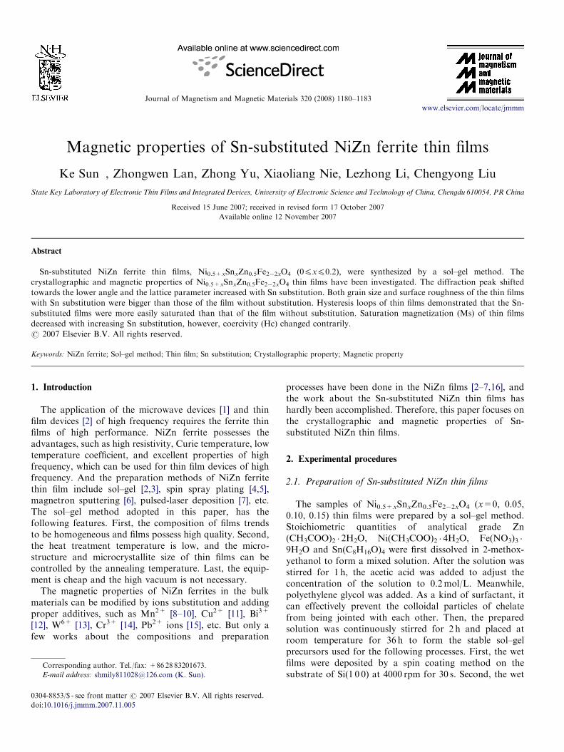
Fig. 2. Lattice parameter and diffraction angle of Ni0.5+xSnxZn0.5Fe2�2xO4 thin films.
K. Sun et al. / Journal of Magnetism and Magnetic Materials 320 (2008) 1180–1183 1181
films were dried at 100 1C for 10min to remove the mixedsolvents. Third, the operation of spin coating and dryingwas repeated to get the required thickness of the films.Last, the dried films were heated at 400 1C for 30min topyrolyze and exclude the organic substances and then wereannealed at 600 1C for 30min in air and cooled slowly inthe furnace. The thickness of the prepared films was about140 nm.
2.2. Characterization and property measurements
The phase identification of the thin films was performedby the Philips X’Pert PRO X-ray diffractometer (XRD),with Cu Ka radiation. The scan pattern is as following:scan range, 2y=25.0050–44.99501; step size, 2y=0.01001;scan step time, t=0.3000 s. The surface morphologies ofthe films were analyzed by atomic force microscopy(AFM), and magnetic measurements by the TOEI VSM-5S-15 vibrating sample magnetometer (VSM) at roomtemperature.
3. Results and discussion
3.1. Phase characterization
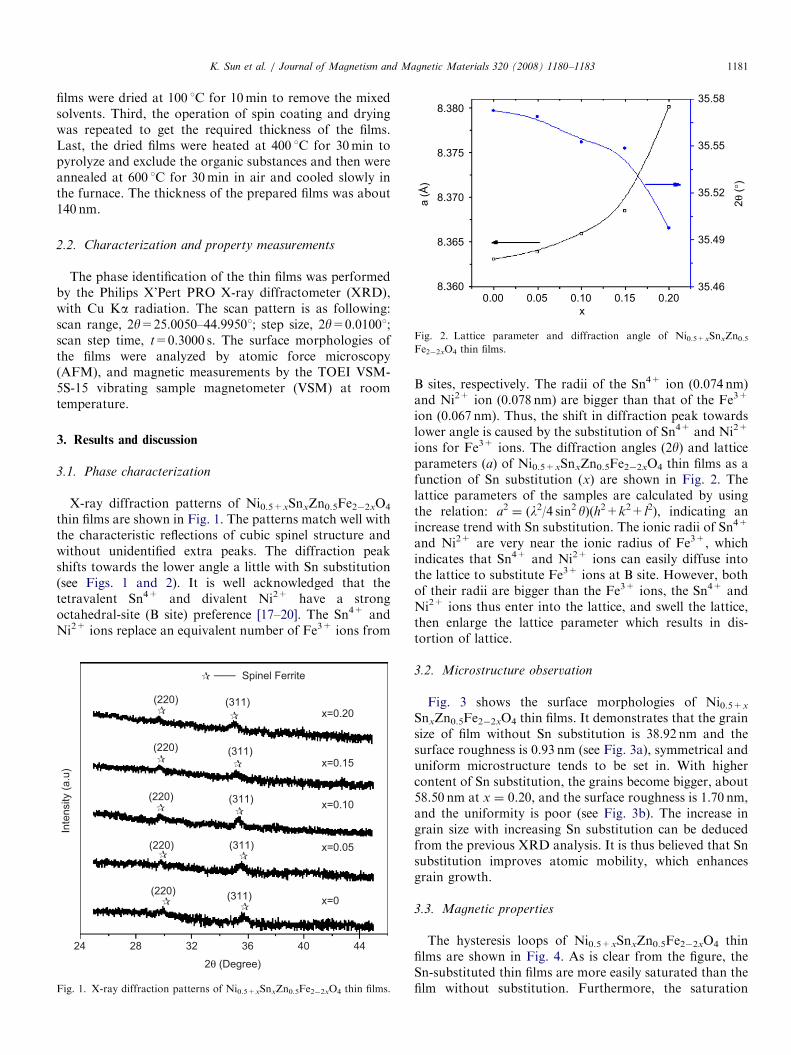
X-ray diffraction patterns of Ni0.5+xSnxZn0.5Fe2�2xO4
thin films are shown in Fig. 1. The patterns match well withthe characteristic reflections of cubic spinel structure andwithout unidentified extra peaks. The diffraction peakshifts towards the lower angle a little with Sn substitution(see Figs. 1 and 2). It is well acknowledged that thetetravalent Sn4+ and divalent Ni2+ have a strongoctahedral-site (B site) preference [17–20]. The Sn4+ andNi2+ ions replace an equivalent number of Fe3+ ions from
Inte
nsi
ty (
a.u
)
24 28 32 36 40 44
2θ (Degree)
(220)
(220)
(311)
(311)
(220) (311)
(220) (311)
(220) (311)
x=0
x=0.05
x=0.10
x=0.15
x=0.20
Spinel Ferrite
Fig. 1. X-ray diffraction patterns of Ni0.5+xSnxZn0.5Fe2�2xO4 thin films.
B sites, respectively. The radii of the Sn4+ ion (0.074 nm)and Ni2+ ion (0.078 nm) are bigger than that of the Fe3+
ion (0.067 nm). Thus, the shift in diffraction peak towardslower angle is caused by the substitution of Sn4+ and Ni2+
ions for Fe3+ ions. The diffraction angles (2y) and latticeparameters (a) of Ni0.5+xSnxZn0.5Fe2�2xO4 thin films as afunction of Sn substitution (x) are shown in Fig. 2. Thelattice parameters of the samples are calculated by usingthe relation: a2 ¼ (l2/4 sin2 y)(h2+k2+l2), indicating anincrease trend with Sn substitution. The ionic radii of Sn4+
and Ni2+ are very near the ionic radius of Fe3+, whichindicates that Sn4+ and Ni2+ ions can easily diffuse intothe lattice to substitute Fe3+ ions at B site. However, bothof their radii are bigger than the Fe3+ ions, the Sn4+ andNi2+ ions thus enter into the lattice, and swell the lattice,then enlarge the lattice parameter which results in dis-tortion of lattice.
3.2. Microstructure observation
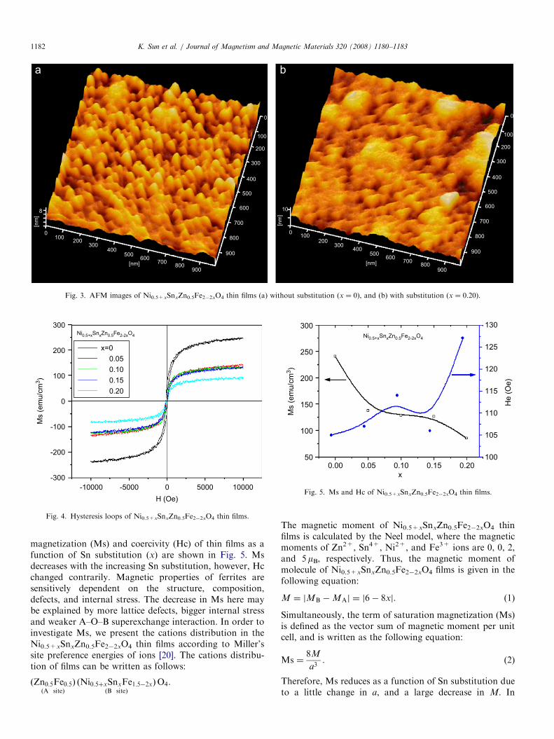
Fig. 3 shows the surface morphologies of Ni0.5+x
SnxZn0.5Fe2�2xO4 thin films. It demonstrates that the grainsize of film without Sn substitution is 38.92 nm and thesurface roughness is 0.93 nm (see Fig. 3a), symmetrical anduniform microstructure tends to be set in. With highercontent of Sn substitution, the grains become bigger, about58.50 nm at x ¼ 0.20, and the surface roughness is 1.70 nm,and the uniformity is poor (see Fig. 3b). The increase ingrain size with increasing Sn substitution can be deducedfrom the previous XRD analysis. It is thus believed that Snsubstitution improves atomic mobility, which enhancesgrain growth.
3.3. Magnetic properties
The hysteresis loops of Ni0.5+xSnxZn0.5Fe2�2xO4 thinfilms are shown in Fig. 4. As is clear from the figure, theSn-substituted thin films are more easily saturated than thefilm without substitution. Furthermore, the saturation
ARTICLE IN PRESS[n
m]
[nm
]
8 10
0
0
100
100
200
200
300
300
400
400
500
500
600
600
700
700
800
800
900
900
[nm]
0
0
100
100
200
200
300
300
400
400
500
500
600
600
700
700
800
800
900
900
[nm]
Fig. 3. AFM images of Ni0.5+xSnxZn0.5Fe2�2xO4 thin films (a) without substitution (x ¼ 0), and (b) with substitution (x ¼ 0.20).
300
200
100
0
-100
-200
-300
Ms
(em
u/c
m3)
-10000 -5000 0 5000 10000
H (Oe)
x=0
0.05
0.10
0.15
0.20
Ni0.5+xSnxZn0.5Fe2-2xO4
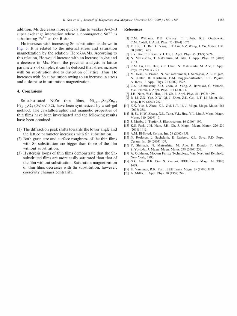
Fig. 4. Hysteresis loops of Ni0.5+xSnxZn0.5Fe2�2xO4 thin films.
300
250
200
150
100
50
Ms
(em
u/c
m3)
0.00 0.05 0.10 0.15 0.20x
130
125
120
115
110
105
100
He
(O
e)
Ni0.5+xSnxZn0.5Fe2-2xO4
Fig. 5. Ms and Hc of Ni0.5+xSnxZn0.5Fe2�2xO4 thin films.
K. Sun et al. / Journal of Magnetism and Magnetic Materials 320 (2008) 1180–11831182
magnetization (Ms) and coercivity (Hc) of thin films as afunction of Sn substitution (x) are shown in Fig. 5. Msdecreases with the increasing Sn substitution, however, Hcchanged contrarily. Magnetic properties of ferrites aresensitively dependent on the structure, composition,defects, and internal stress. The decrease in Ms here maybe explained by more lattice defects, bigger internal stressand weaker A–O–B superexchange interaction. In order toinvestigate Ms, we present the cations distribution in theNi0.5+xSnxZn0.5Fe2�2xO4 thin films according to Miller’ssite preference energies of ions [20]. The cations distribu-tion of films can be written as follows:
ðZn0:5Fe0:5ÞðA siteÞ
ðNi0:5þxSnxFe1:5�2xÞðB siteÞ
O4.
The magnetic moment of Ni0.5+xSnxZn0.5Fe2�2xO4 thinfilms is calculated by the Neel model, where the magneticmoments of Zn2+, Sn4+, Ni2+, and Fe3+ ions are 0, 0, 2,and 5 mB, respectively. Thus, the magnetic moment ofmolecule of Ni0.5+xSnxZn0.5Fe2�2xO4 films is given in thefollowing equation:
M ¼ jMB �MAj ¼ j6� 8xj. (1)
Simultaneously, the term of saturation magnetization (Ms)is defined as the vector sum of magnetic moment per unitcell, and is written as the following equation:
Ms ¼8M
a3. (2)
Therefore, Ms reduces as a function of Sn substitution dueto a little change in a, and a large decrease in M. In
ARTICLE IN PRESSK. Sun et al. / Journal of Magnetism and Magnetic Materials 320 (2008) 1180–1183 1183
addition, Ms decreases more quickly due to weaker A–O–Bsuper exchange interaction where a nonmagnetic Sn4+ issubstituting Fe3+ at the B site.
Hc increases with increasing Sn substitution as shown inFig. 5. It is related to the internal stress and saturationmagnetization by the relation: Hcplss/Ms. According tothis relation, Hc would increase with an increase in lss anda decrease in Ms. From the previous analysis in latticeparameters of samples, it can be deduced that stress increasewith Sn substitution due to distortion of lattice. Thus, Hcincreases with Sn substitution owing to an increase in stressand a decrease in saturation magnetization.
4. Conclusions
Sn-substituted NiZn thin films, Ni0.5+xSnxZn0.5Fe2�2xO4 (0pxp0.2), have been synthesized by a sol–gelmethod. The crystallographic and magnetic properties ofthin films have been investigated and the following resultshave been obtained:
(1)
The diffraction peak shifts towards the lower angle andthe lattice parameter increases with Sn substitution.(2)
Both grain size and surface roughness of the thin filmswith Sn substitution are bigger than those of the filmwithout substitution.(3)
Hysteresis loops of thin films demonstrate that the Sn-substituted films are more easily saturated than that ofthe film without substitution. Saturation magnetizationof thin films decreases with Sn substitution, however,coercivity changes contrarily.References
[1] C.M. Williams, D.B. Chrisey, P. Lubitz, K.S. Grabowski,
C.M. Cotell, J. Appl. Phys. 75 (1994) 1676.
[2] F. Liu, T.L. Ren, C. Yang, L.T. Liu, A.Z. Wang, J. Yu, Mater. Lett.
60 (2006) 1403.
[3] S.Y. Bae, C.S. Kim, Y.J. Oh, J. Appl. Phys. 85 (1999) 5226.
[4] N. Matsushita, T. Nakamura, M. Abe, J. Appl. Phys. 93 (2003)
7133.
[5] C.M. Fu, H.S. Hsu, Y.C. Chao, N. Matsushita, M. Abe, J. Appl.
Phys. 93 (2003) 7127.
[6] M. Desai, S. Prasad, N. Venkataramani, I. Samajdar, A.K. Nigam,
N. Keller, R. Krishnan, E.M. Baggio-Saitovitch, B.R. Pujada,
A. Rossi, J. Appl. Phys. 91 (2002) 7592.
[7] C.N. Chinnasamy, S.D. Yoon, A. Yang, A. Baraskar, C. Vittoria,
V.G. Harris, J. Appl. Phys. 101 (2007) 1.
[8] J.H. Nam, W.G. Hur, J.H. Oh, J. Appl. Phys. 81 (1997) 4794.
[9] B. Li, Z.X. Yue, X.W. Qi, J. Zhou, Z.L. Gui, L.T. Li, Mater. Sci.
Eng., B 99 (2003) 252.
[10] Z.X. Yue, J. Zhou, Z.L. Gui, L.T. Li, J. Magn. Magn. Mater. 264
(2003) 258.
[11] H. Su, H.W. Zhang, X.L. Tang, Y.L. Jing, Y.L. Liu, J. Magn. Magn.
Mater. 310 (2007) 17.
[12] J. Murbe, J. Topfer, J. Electroceram. 16 (2006) 199.
[13] K.S. Park, J.H. Nam, J.H. Oh, J. Magn. Magn. Mater. 226–230
(2001) 1415.
[14] A.M. El-Sayed, Ceram. Int. 28 (2002) 651.
[15] N. Rezlescu, L. Sachelarie, E. Rezlescu, C.L. Sava, P.D. Popa,
Ceram. Int. 29 (2003) 107.
[16] Y. Shimada, N. Matsushita, M. Abe, K. Kondo, T. Chiba,
S. Yoshida, J. Magn. Magn. Mater. 278 (2004) 256.
[17] A. Goldman, Modern Ferrite Technology, Van Nostrand Reinhold,
New York, 1990.
[18] G.C. Jain, B.K. Das, S. Kumari, IEEE Trans. Magn. 16 (1980)
1428.
[19] U. Varshney, R.K. Puri, IEEE Trans. Magn. 25 (1989) 3109.
[20] A. Miller, J. Appl. Phys. 30 (1959) 24S.