magnetic sensor for arterial distension and blood … sensor for arterial distension and blood...
TRANSCRIPT
Biomed Microdevices (2014) 16:815–827DOI 10.1007/s10544-014-9885-x
Magnetic sensor for arterial distension and blood pressuremonitoring
Johannes Ruhhammer · Tamara Herbstritt · Dominic Ruh ·Katharina Foerster · Claudia Heilmann · Friedhelm Beyersdorf ·Frank Goldschmidtboeing · Andreas Seifert · Peter Woias
Published online: 16 July 2014© Springer Science+Business Media New York 2014
Abstract A novel sensor for measuring arterial distension,pulse and pressure waveform is developed and evaluated.The system consists of a magnetic sensor which is appliedand fixed to arterial vessels without any blood vessel con-striction, hence avoiding stenosis. The measurement princi-ple could be validated by in vitro experiments on siliconetubes, and by in vivo experiments in an animal model,thereby indicating the non-linear viscoelastic characteris-tics of real blood vessels. The sensor is capable to provideabsolute measurements of the dynamically varying arterialdiameter. By calibrating the sensor, a long-term monitoringsystem for continuously measuring blood pressure and othercardiovascular parameters could be developed based on themethod described. This will improve diagnostics for highrisk patients and enable a better, specific treatment.
Keywords In vivo monitoring · Cardiovascularparameters · Blood pressure · Arterial distension ·Magnetic sensor · Implant
1 Introduction
Cardiovascular diseases (CVDs) are the single leading causeof death worldwide. According to the global status report
J. Ruhhammer (�) · T. Herbstritt · D. Ruh ·F. Goldschmidtboeing · A. Seifert · P. WoiasDepartment of Microsystems Engineering, University of Freiburg,Georges-Koehler-Allee 102, 79110 Freiburg, Germanye-mail: [email protected]
K. Foerster · C. Heilmann · F. BeyersdorfDepartment of Cardiovascular Surgery, University MedicalCenter, Hugstetter Str. 55, 79106 Freiburg, Germany
on non-communicable diseases (NCDs) of 2010, more peo-ple died from CVDs than from any other reason (WorldHealth Organization 2011) . By definition, NCDs are non-infectious and non-transmissible diseases.
Treatment of CVDs and therapeutic measures forpatients with CVDs require a clinical evaluation of thepatients’ hemodynamic status. Improved diagnostic toolscan decrease the rehospitalization rate. In 2005, 17.6 %of Medicare beneficiaries were readmitted within 30 daysafter discharge, and the rate of potentially preventable read-missions was 13.3 % (Medpac 2007). Among these read-missions, the highest number can be associated with heartfailure. However, optimized treatment requires continuouslong-term monitoring of the patients’ hemodynamic param-eters, such as blood pressure, pulse frequency and pressurewaveform.
Blood pressure, as one of the most important hemody-namic factors, can be measured either directly or indirectly.Direct measurement of blood pressure is performed inva-sively by an arterial catheter, considered as the gold standardfor blood pressure measurement.
Methods for indirectly measuring blood pressuremainly feature an air-filled cuff, thereby temporarily stop-ping the blood flow through the artery. When the cuffis deflated, blood pressure can be estimated by applyingvarious measurement techniques. Among these, the mostcommon methods are the auscultatory and oscillometricmeasurements.
Despite different advantages, both direct and indirectmeasurement methods also have their downsides. Directdevices can only be applied in intensive care unit, since acatheter is inserted into an artery. This entails the risk ofsignificant blood loss (hemorrhage), thrombosis (occlusion)or infection. Indirect devices using pressure cuffs are onthe one hand non-invasive, but can on the other hand only
816 Biomed Microdevices (2014) 16:815–827
measure single values. Quasi-continuous monitoring is per-formed by frequent repetitions of the measurement everycouple of minutes. Both approaches do restrict the patient’smobility and daily routine.
Implantable sensors, on the other hand, enable continu-ous long-term monitoring of blood pressure. There are somecommercially available sensors where the pressure tip isplaced near the right ventricular outflow tract (Steinhauset al. 2005). These systems are able to continuously measureintracardiac pressure, heart rate and activity. The disadvan-tage of these sensors is that they are inserted directly intothe heart, requiring a complex surgical procedure with therisk of serious infections and thrombosis.
A completely different approach is realized byimplantable extravascular cuff sensors which are placedaround blood vessels. B. Ziaie and K. Najafi demonstrateda device where a pressure sensor is pressed against theblood vessel for tonometric blood pressure measurement(Ziaie and Najafi 2001). By this method, the blood vesselis significantly deformed, thereby changing physiologicalproperties.
A flexible device which adapts to the radius of the arterywas developed by K.-H. Shin et al. (Shin et al. 2004). Thedevice consists of a thinned silicon chip embedded in aflexible polyimide substrate. The silicon chip acts as a flex-ible capacitor, changing capacitance upon deformation. Aninductor coil is directly integrated into the polyimide form-ing an LC resonator together with the capacitor. The passivedevice can be read out from the outside by an external induc-tor coil. The readout method limits the implant positionand requires a place near the body surface. Another draw-back is the need of an external inductor coil and associatedelectronics.
A different extravascular implantable system was shownby P. Cong et al. (Cong et al. 2006), where a fluid-filled cuffincluding a MEMS pressure sensor is attached to the bloodvessel. The cuff is made of biocompatible soft silicone.During the measurement, a baseline drift occurs, which isexplained by the authors by the soft nature of the outer wallof the cuff. The pressure inside the cuff is quite sensitive todeformations of the cuff by the surrounding tissue, therebyincreasing the pressure acting on the pressure sensor. Theeffect could be reduced by stiffening the outside wall with ametal ring causing increased vessel restraints. A disadvan-tage of this approach is the fixed diameter of the cuff at thetime of implantation.
P. Bingger et al proposed a flexible and elastic straingauge which is wrapped around an artery and fixed bystandard titanium ligature clips (Bingger et al. 2012). Thisdesign offers a high flexibility since the length of the sen-sor can be adjusted appropriate to the radius of the artery.The sensor consists of a flexible silicone strip with embed-ded interdigital finger structures made of PEDOT/PSS, an
intrinsically conductive polymer. By use of a soft silicone,vessel constriction is mostly avoided. The missing shieldingand large water uptake of the PEDOT/PSS leads to a highsusceptibility to breathing and other disturbances. Specialcare has to be taken during the implantation of the sensorstrip since PEDOT/PSS is very brittle, and high strain couldeasily destroy the sensor structure.
M. Theodor et al. presented an extravascular measure-ment method based on acceleration sensors (Theodor et al.2014). The blood pressure is derived indirectly by the mea-surement of the reflected wave transit time (RWTT). Themethod shows a strong coupling between RWTT and sys-tolic blood pressure. The system benefits from its flexibilityregarding the implantation site. The accelerometers of thesystem can either be placed diametrically on opposite sidesof an artery, or subcutaneously on a thin layer of connectivetissue and one sensor directly above an artery. The elimina-tion of strong movement artifacts is still challenging, eventhough a two-sensor concept has been chosen to eliminatethose.
Our proposed method is designed as an extravascularsensor system based on a magnetic sensing principle. Themethod shows the advantages of both, direct and indirectdevices, and allows continuous measurements of arterialstrain with high accuracy and no vessel constriction. Arterialstrain correlates with the blood pressure waveform givingnew insights into the biomechanics of the arterial wall. Thedetermination of the absolute diameter is accessible withminimum calibration effort.
In the following, the design and theoretical backgroundof the proposed sensor are presented, and the capability ofthis new approach is demonstrated by in vitro as well as invivo measurements. The results illustrate that the sensor isable to measure absolute dynamic diameters and the correla-tion to the interior pressure of artificial blood vessels madeof silicone. Moreover, the sensor was tested in an animalmodel with real blood vessels, and we could demonstrate thenon-linear viscoelastic characteristics in situ. Additionally,we could show by histological examinations after long-term implantation that the materials employed promise highbiocompatibility.
2 Method
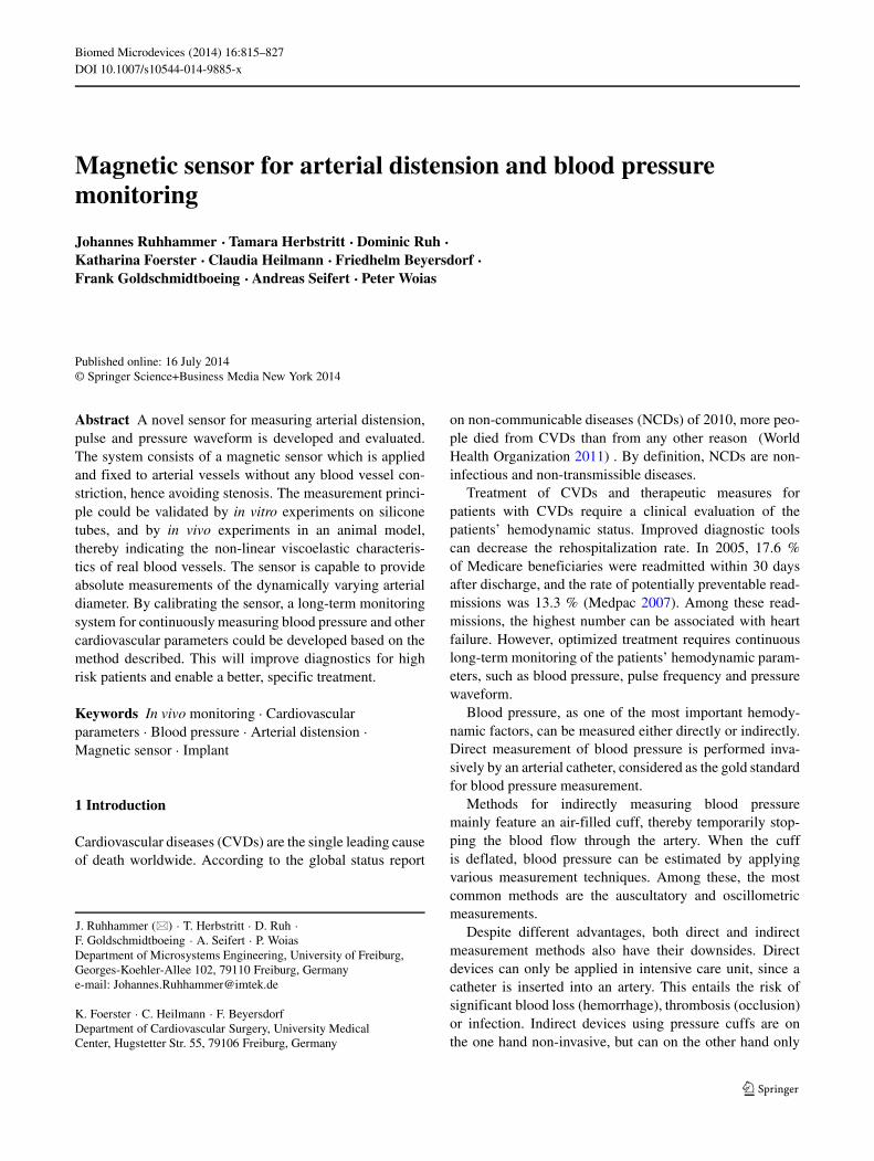
The sensor system is designed to measure arterial disten-sion extravascularly, directly at arteries of the circulatorysystem. Two flexible substrates are fixed by highly elas-tic and soft silicone strips on opposite sides of an artery.A microstructured design of the strips and direct integra-tion of the locking system into the substrates provides both,a tight locking of the silicone strips and stepwise adjust-ing of the mounting force. The two substrates are equipped
Biomed Microdevices (2014) 16:815–827 817
with a Hall sensor and a permanent magnet, respectively, asdepicted in Fig. 1. By using a very soft silicone, blood vesselconstriction and restraints of the vessel, which could altermeasurement results, are minimized.
When the diameter of the blood vessel varies, the dis-tance between Hall sensor and magnet changes leading to analteration of the output voltage of the Hall sensor. By match-ing the strength of the permanent magnet to the sensitivityand measurement range of the Hall sensor, a high resolu-tion of the measurement method is achieved. According tothe European standard EN-1060, the accuracy for a bloodpressure measurement system must agree with the mercurystandard of 5 mmHg for the mean difference and a standarddeviation not greater than 8 mmHg (O’Brien et al. 2001).
The magnetic sensor will finally measure the arterial dis-tension, even though by an indirect method. Static bloodpressure is related to arterial distension by the incrementalelastic modulus (Bergel 1961)
Einc = �p
�R× 2(1 − σ 2)R2
i Ro
(R2o − R2
i ), (1)
where �R is the radial displacement due to a pressurechange �p, σ is the Poisson’s ratio, Ri and Ro are the innerand outer radii of the artery. The Poisson’s ratio σ is oftentaken to be 0.5 (Bergel 1961; Newman et al. 1975; Nicholset al. 2011). In the case of dynamic pressure variations, thearterial wall shows a non-linear viscoelastic behavior.
Since it is very often difficult to obtain correct values forthe arterial wall thickness, a pressure-strain elastic modulus,also called Peterson’s elastic modulus, Ep was introducedby Petersen (Peterson et al. 1960),
Ep = DdPs − Pd
Ds − Dd
(2)
where (Ps −Pd) and (Ds −Dd) are pulse pressure and pulsediameter, respectively, and Dd is the end-diastolic diameter.
Fig. 1 CAD drawing of the sensor system fixed to the artery. The topsubstrate is equipped with a Hall sensor and the bottom substrate witha permanent magnet. The two substrates are fixed on the artery byhighly elastic and soft silicone strips
Young’s elastic modulus and Peterson’s elastic modulus arerelated to each other by
EYoung = Ep/hrel , (3)
where hrel is the relative wall thickness given by
hrel = Ro − Ri
Ri
. (4)
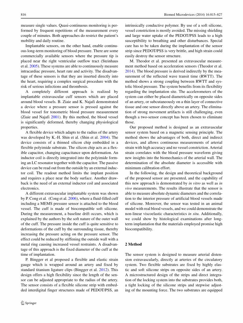
For clarification, see Fig. 2.The sensor measures the absolute value of the diameter
and hence the pulse diameter defined in Eq. 2. With theknowledge of Peterson’s elastic modulus, the pulse pressuremay be calculated by the same equation.
3 Estimation of magnetic operating point
For optimum operation with high sensitivity, the magneticfield must be below the saturation limit of the Hall sensorand should have a maximized gradient. Besides the mate-rial of the permanent magnet, the dimensions determine thestrength of the magnetic field and can be calculated by usingequivalent volume and surface currents. A derivation of themagnetic field theory based on equivalent currents is shownin (Furlani 2001). The magnetic field of a permanent mag-net polarized along its axis with a uniform magnetizationMs is given by
B(r, z) = μ0
4π
∫ L
0
∫ 2π
0. . .
Ms
[(z − z′) cos φx + (z − z′) sin φy + (R − r cos φ)z
]Rdφdz′
[r2 + R2 − 2rR cos(φ) + (z − z′)2
]3/2(5)
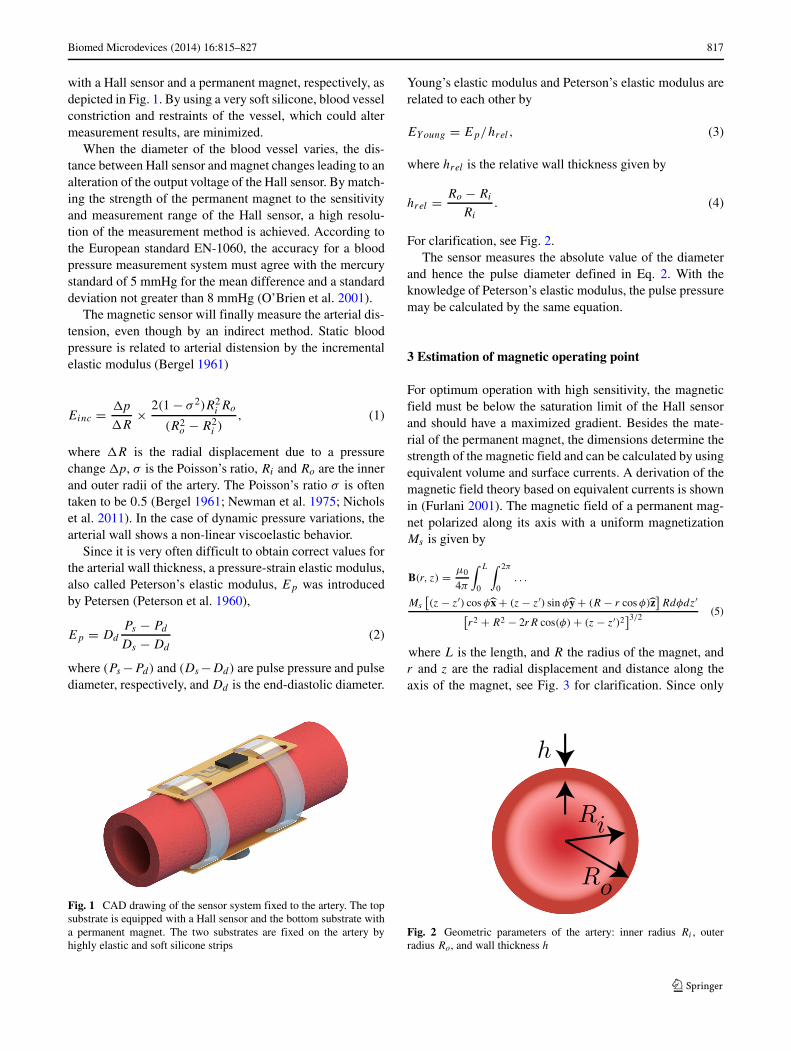
where L is the length, and R the radius of the magnet, andr and z are the radial displacement and distance along theaxis of the magnet, see Fig. 3 for clarification. Since only
Fig. 2 Geometric parameters of the artery: inner radius Ri , outerradius Ro, and wall thickness h
818 Biomed Microdevices (2014) 16:815–827
Fig. 3 Orientation and coordinates of the cylindrical permanent mag-net with magnetic field in z-direction Bz, radius R, and length L
the z-component can be measured by the Hall sensor, Eq. 5reduces to
Bz(r, z) = μ0
4π
∫ L
0
∫ 2π
0. . .
Ms(R − r cos φ)Rdφdz′
[r2 + R2 − 2rR cos(φ) + (z − z′)2]3/2. (6)
In the case where the Hall sensor and magnet are per-fectly parallel and no misalignment is assumed, hencer = 0, Eq. 6 yields
Bz(z) = 1
2Msμ0
(d√
d2 + R2+ L − d√
(d − L)2 + R2
)(7)
The strength of the permanent magnet can be estimatedby Eq. 7. By using a NdFeB magnet to generate the mag-netic field at the Hall sensor, a relative permeability of ∼ 1and a residual flux density of Br = 1.37 − 1.42 T, accord-ing to the data sheet (Webcraft GmbH) can be assumed. Themagnetization can be calculated to Ms = Br/μ0, where μ0
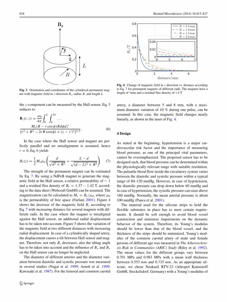
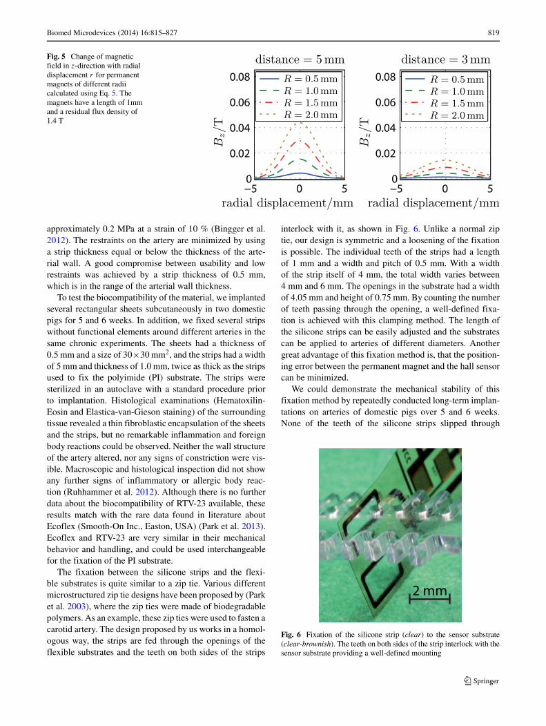
is the permeability of free space (Furlani 2001). Figure 4shows the decrease of the magnetic field Bz according toEq. 7 with increasing distance for several magnets with dif-ferent radii. In the case where the magnet is misalignedagainst the Hall sensor, an additional radial displacementhas to be taken into account. Figure 5 shows the variation ofthe magnetic field at two different distances with increasingradial displacement. In case of a cylindrically shaped artery,the displacement causes a tilt between Hall sensor and mag-net. Therefore, not only Bz decreases, also the tilting anglehas to be taken into account and the influence of Bx and By
on the Hall sensor can no longer be neglected.The diameter of different arteries and the diameter vari-
ation between diastolic and systolic pressure was measuredin several studies (Nagai et al. 1999; Arnett et al. 1999;Kawasaki et al. 1987). For the femoral and common carotid
Fig. 4 Change of magnetic field in z-direction vs. distance accordingto Eq. 7 for permanent magnets of different radii. The magnets have alength of 1mm and a residual flux density of 1.4 T
artery, a diameter between 5 and 8 mm, with a maxi-mum diameter variation of 10 % during one pulse, can beassumed. In this case, the magnetic field changes nearlylinearly, as shown in the inset of Fig. 4.
4 Design
As stated at the beginning, hypertension is a major car-diovascular risk factor and the importance of measuringblood pressure, as one of the principal vital parameters,cannot be overemphasized. The proposed sensor has to bedesigned such, that blood pressure can be determined withinthe physiologically relevant range with suitable resolution.The pulsatile blood flow inside the circulatory system variesbetween the diastolic and systolic pressure within a typicalrange of 80–120 mmHg. However, in case of hypotension,the diastolic pressure can drop down below 60 mmHg andin case of hypertension, the systolic pressure can raise above180 mmHg. Normally, the mean arterial pressure is about100 mmHg (Pauca et al. 2001).
The material used for the silicone strips to hold theflexible substrates in place has to meet certain require-ments. It should be soft enough to avoid blood vesselconstriction and minimize impairments on the dynamicbehavior of the system. Therefore, its Young’s modulusshould be lower than that of the blood vessel, and thethickness of the strips should be minimized. Young’s mod-ulus of the common carotid artery of male and femalepersons of different age was measured in The Atherosclero-sis Risk in Communities (ARIC) Study (Riley et al. 1992).The mean values for the different groups vary between0.701 MPa and 0.983 MPa with a mean wall thicknessbetween 0.553 mm and 0.735 mm. As an appropriate sil-icone, we chose Neukasil RTV-23 (Altropol KunststoffGmbH, Stockelsdorf, Germany) with a Young’s modulus of
Biomed Microdevices (2014) 16:815–827 819
Fig. 5 Change of magneticfield in z-direction with radialdisplacement r for permanentmagnets of different radiicalculated using Eq. 5. Themagnets have a length of 1mmand a residual flux density of1.4 T
approximately 0.2 MPa at a strain of 10 % (Bingger et al.2012). The restraints on the artery are minimized by usinga strip thickness equal or below the thickness of the arte-rial wall. A good compromise between usability and lowrestraints was achieved by a strip thickness of 0.5 mm,which is in the range of the arterial wall thickness.
To test the biocompatibility of the material, we implantedseveral rectangular sheets subcutaneously in two domesticpigs for 5 and 6 weeks. In addition, we fixed several stripswithout functional elements around different arteries in thesame chronic experiments. The sheets had a thickness of0.5 mm and a size of 30×30 mm2, and the strips had a widthof 5 mm and thickness of 1.0 mm, twice as thick as the stripsused to fix the polyimide (PI) substrate. The strips weresterilized in an autoclave with a standard procedure priorto implantation. Histological examinations (Hematoxilin-Eosin and Elastica-van-Gieson staining) of the surroundingtissue revealed a thin fibroblastic encapsulation of the sheetsand the strips, but no remarkable inflammation and foreignbody reactions could be observed. Neither the wall structureof the artery altered, nor any signs of constriction were vis-ible. Macroscopic and histological inspection did not showany further signs of inflammatory or allergic body reac-tion (Ruhhammer et al. 2012). Although there is no furtherdata about the biocompatibility of RTV-23 available, theseresults match with the rare data found in literature aboutEcoflex (Smooth-On Inc., Easton, USA) (Park et al. 2013).Ecoflex and RTV-23 are very similar in their mechanicalbehavior and handling, and could be used interchangeablefor the fixation of the PI substrate.
The fixation between the silicone strips and the flexi-ble substrates is quite similar to a zip tie. Various differentmicrostructured zip tie designs have been proposed by (Parket al. 2003), where the zip ties were made of biodegradablepolymers. As an example, these zip ties were used to fasten acarotid artery. The design proposed by us works in a homol-ogous way, the strips are fed through the openings of theflexible substrates and the teeth on both sides of the strips
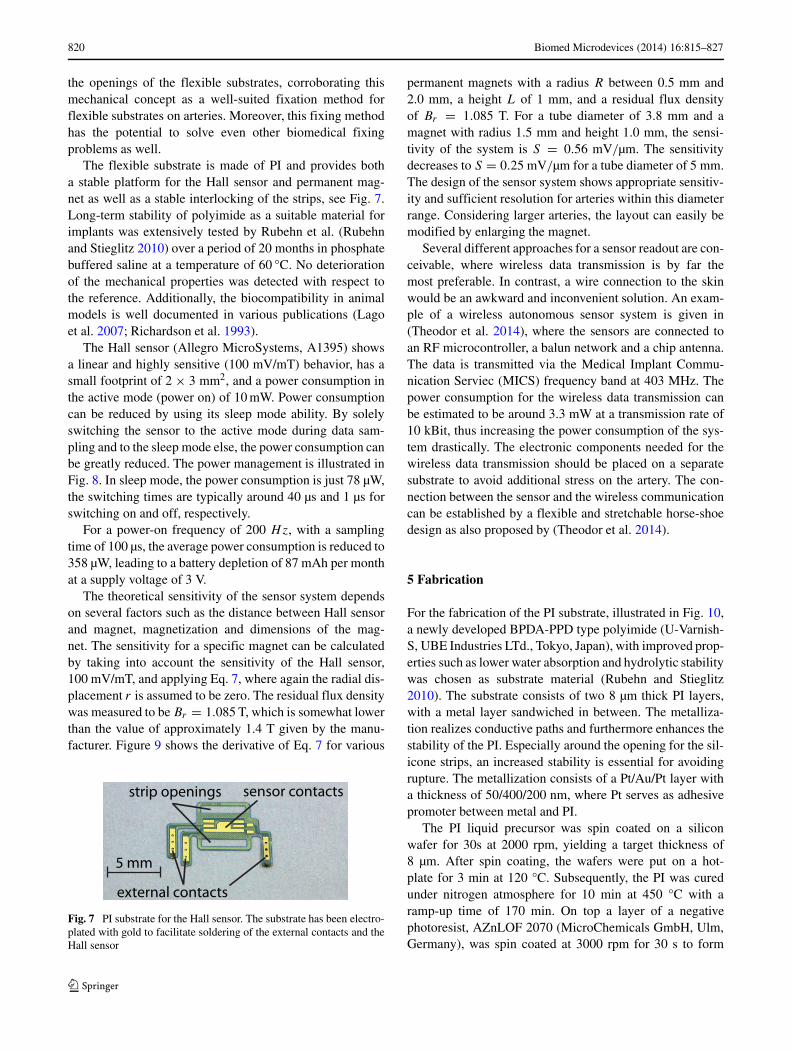
interlock with it, as shown in Fig. 6. Unlike a normal ziptie, our design is symmetric and a loosening of the fixationis possible. The individual teeth of the strips had a lengthof 1 mm and a width and pitch of 0.5 mm. With a widthof the strip itself of 4 mm, the total width varies between4 mm and 6 mm. The openings in the substrate had a widthof 4.05 mm and height of 0.75 mm. By counting the numberof teeth passing through the opening, a well-defined fixa-tion is achieved with this clamping method. The length ofthe silicone strips can be easily adjusted and the substratescan be applied to arteries of different diameters. Anothergreat advantage of this fixation method is, that the position-ing error between the permanent magnet and the hall sensorcan be minimized.
We could demonstrate the mechanical stability of thisfixation method by repeatedly conducted long-term implan-tations on arteries of domestic pigs over 5 and 6 weeks.None of the teeth of the silicone strips slipped through
2 mm
Fig. 6 Fixation of the silicone strip (clear) to the sensor substrate(clear-brownish). The teeth on both sides of the strip interlock with thesensor substrate providing a well-defined mounting
820 Biomed Microdevices (2014) 16:815–827
the openings of the flexible substrates, corroborating thismechanical concept as a well-suited fixation method forflexible substrates on arteries. Moreover, this fixing methodhas the potential to solve even other biomedical fixingproblems as well.
The flexible substrate is made of PI and provides botha stable platform for the Hall sensor and permanent mag-net as well as a stable interlocking of the strips, see Fig. 7.Long-term stability of polyimide as a suitable material forimplants was extensively tested by Rubehn et al. (Rubehnand Stieglitz 2010) over a period of 20 months in phosphatebuffered saline at a temperature of 60 °C. No deteriorationof the mechanical properties was detected with respect tothe reference. Additionally, the biocompatibility in animalmodels is well documented in various publications (Lagoet al. 2007; Richardson et al. 1993).
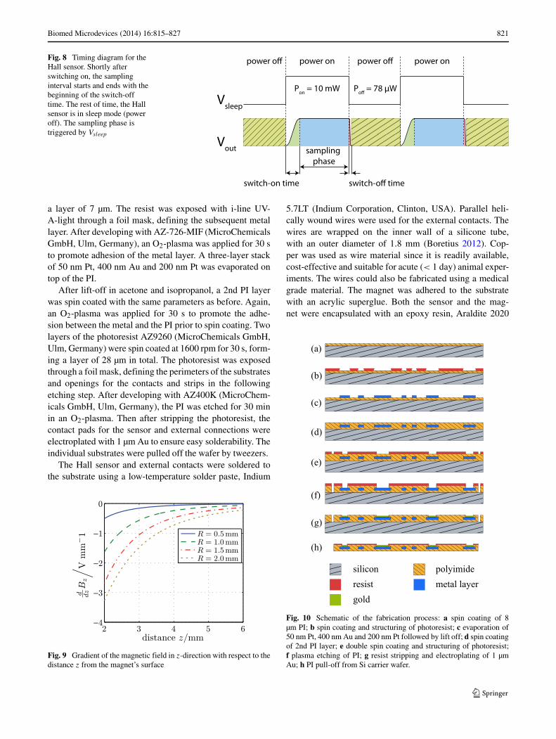
The Hall sensor (Allegro MicroSystems, A1395) showsa linear and highly sensitive (100 mV/mT) behavior, has asmall footprint of 2 × 3 mm2, and a power consumption inthe active mode (power on) of 10 mW. Power consumptioncan be reduced by using its sleep mode ability. By solelyswitching the sensor to the active mode during data sam-pling and to the sleep mode else, the power consumption canbe greatly reduced. The power management is illustrated inFig. 8. In sleep mode, the power consumption is just 78 µW,the switching times are typically around 40 µs and 1 µs forswitching on and off, respectively.
For a power-on frequency of 200 Hz, with a samplingtime of 100 µs, the average power consumption is reduced to358 µW, leading to a battery depletion of 87 mAh per monthat a supply voltage of 3 V.
The theoretical sensitivity of the sensor system dependson several factors such as the distance between Hall sensorand magnet, magnetization and dimensions of the mag-net. The sensitivity for a specific magnet can be calculatedby taking into account the sensitivity of the Hall sensor,100 mV/mT, and applying Eq. 7, where again the radial dis-placement r is assumed to be zero. The residual flux densitywas measured to be Br = 1.085 T, which is somewhat lowerthan the value of approximately 1.4 T given by the manu-facturer. Figure 9 shows the derivative of Eq. 7 for various
5 mm
external contacts
sensor contactsstrip openings
Fig. 7 PI substrate for the Hall sensor. The substrate has been electro-plated with gold to facilitate soldering of the external contacts and theHall sensor
permanent magnets with a radius R between 0.5 mm and2.0 mm, a height L of 1 mm, and a residual flux densityof Br = 1.085 T. For a tube diameter of 3.8 mm and amagnet with radius 1.5 mm and height 1.0 mm, the sensi-tivity of the system is S = 0.56 mV/µm. The sensitivitydecreases to S = 0.25 mV/µm for a tube diameter of 5 mm.The design of the sensor system shows appropriate sensitiv-ity and sufficient resolution for arteries within this diameterrange. Considering larger arteries, the layout can easily bemodified by enlarging the magnet.
Several different approaches for a sensor readout are con-ceivable, where wireless data transmission is by far themost preferable. In contrast, a wire connection to the skinwould be an awkward and inconvenient solution. An exam-ple of a wireless autonomous sensor system is given in(Theodor et al. 2014), where the sensors are connected toan RF microcontroller, a balun network and a chip antenna.The data is transmitted via the Medical Implant Commu-nication Serviec (MICS) frequency band at 403 MHz. Thepower consumption for the wireless data transmission canbe estimated to be around 3.3 mW at a transmission rate of10 kBit, thus increasing the power consumption of the sys-tem drastically. The electronic components needed for thewireless data transmission should be placed on a separatesubstrate to avoid additional stress on the artery. The con-nection between the sensor and the wireless communicationcan be established by a flexible and stretchable horse-shoedesign as also proposed by (Theodor et al. 2014).
5 Fabrication
For the fabrication of the PI substrate, illustrated in Fig. 10,a newly developed BPDA-PPD type polyimide (U-Varnish-S, UBE Industries LTd., Tokyo, Japan), with improved prop-erties such as lower water absorption and hydrolytic stabilitywas chosen as substrate material (Rubehn and Stieglitz2010). The substrate consists of two 8 µm thick PI layers,with a metal layer sandwiched in between. The metalliza-tion realizes conductive paths and furthermore enhances thestability of the PI. Especially around the opening for the sil-icone strips, an increased stability is essential for avoidingrupture. The metallization consists of a Pt/Au/Pt layer witha thickness of 50/400/200 nm, where Pt serves as adhesivepromoter between metal and PI.
The PI liquid precursor was spin coated on a siliconwafer for 30s at 2000 rpm, yielding a target thickness of8 µm. After spin coating, the wafers were put on a hot-plate for 3 min at 120 °C. Subsequently, the PI was curedunder nitrogen atmosphere for 10 min at 450 °C with aramp-up time of 170 min. On top a layer of a negativephotoresist, AZnLOF 2070 (MicroChemicals GmbH, Ulm,Germany), was spin coated at 3000 rpm for 30 s to form
Biomed Microdevices (2014) 16:815–827 821
Fig. 8 Timing diagram for theHall sensor. Shortly afterswitching on, the samplinginterval starts and ends with thebeginning of the switch-offtime. The rest of time, the Hallsensor is in sleep mode (poweroff). The sampling phase istriggered by Vsleep
Vsleep
Vout
switch-on time
sampling phase
switch-off time
Pon = 10 mW Poff = 78 μW
power off power on power off power on
a layer of 7 µm. The resist was exposed with i-line UV-A-light through a foil mask, defining the subsequent metallayer. After developing with AZ-726-MIF (MicroChemicalsGmbH, Ulm, Germany), an O2-plasma was applied for 30 sto promote adhesion of the metal layer. A three-layer stackof 50 nm Pt, 400 nm Au and 200 nm Pt was evaporated ontop of the PI.
After lift-off in acetone and isopropanol, a 2nd PI layerwas spin coated with the same parameters as before. Again,an O2-plasma was applied for 30 s to promote the adhe-sion between the metal and the PI prior to spin coating. Twolayers of the photoresist AZ9260 (MicroChemicals GmbH,Ulm, Germany) were spin coated at 1600 rpm for 30 s, form-ing a layer of 28 µm in total. The photoresist was exposedthrough a foil mask, defining the perimeters of the substratesand openings for the contacts and strips in the followingetching step. After developing with AZ400K (MicroChem-icals GmbH, Ulm, Germany), the PI was etched for 30 minin an O2-plasma. Then after stripping the photoresist, thecontact pads for the sensor and external connections wereelectroplated with 1 µm Au to ensure easy solderability. Theindividual substrates were pulled off the wafer by tweezers.
The Hall sensor and external contacts were soldered tothe substrate using a low-temperature solder paste, Indium
Fig. 9 Gradient of the magnetic field in z-direction with respect to thedistance z from the magnet’s surface
5.7LT (Indium Corporation, Clinton, USA). Parallel heli-cally wound wires were used for the external contacts. Thewires are wrapped on the inner wall of a silicone tube,with an outer diameter of 1.8 mm (Boretius 2012). Cop-per was used as wire material since it is readily available,cost-effective and suitable for acute (< 1 day) animal exper-iments. The wires could also be fabricated using a medicalgrade material. The magnet was adhered to the substratewith an acrylic superglue. Both the sensor and the mag-net were encapsulated with an epoxy resin, Araldite 2020
(a)
(b)
(c)
(d)
(e)
(f)
(g)
(h)
silicon polyimide
gold
metal layerresist
Fig. 10 Schematic of the fabrication process: a spin coating of 8µm PI; b spin coating and structuring of photoresist; c evaporation of50 nm Pt, 400 nm Au and 200 nm Pt followed by lift off; d spin coatingof 2nd PI layer; e double spin coating and structuring of photoresist;f plasma etching of PI; g resist stripping and electroplating of 1 µmAu; h PI pull-off from Si carrier wafer.
822 Biomed Microdevices (2014) 16:815–827
(Huntsman, Salt Lake City, USA), to achieve electrical insu-lation and increased stability. Again, the epoxy resin couldbe substituted by a medically approved one, but for theseindividual animal experiments, this epoxy is acceptable.
The silicone strip was fabricated by a molding and cast-ing process. For this, an aluminum mold was machined bymicro-milling. After mixing and degassing of the two com-ponents of the silicone, it was poured into the mold andexcess material was removed using a razor blade. Curingwas carried out at 85 °C for 1.5 h. At the end, the strips canbe easily peeled off from the mold without using any releaseagent.
6 Experimental results
6.1 In vitro experiments
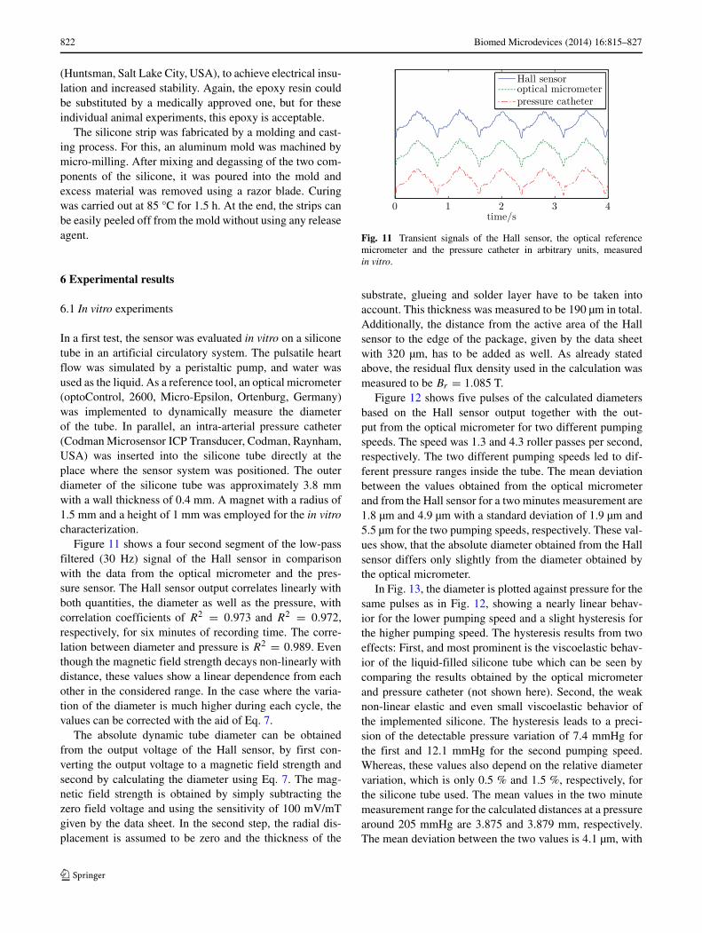
In a first test, the sensor was evaluated in vitro on a siliconetube in an artificial circulatory system. The pulsatile heartflow was simulated by a peristaltic pump, and water wasused as the liquid. As a reference tool, an optical micrometer(optoControl, 2600, Micro-Epsilon, Ortenburg, Germany)was implemented to dynamically measure the diameterof the tube. In parallel, an intra-arterial pressure catheter(Codman Microsensor ICP Transducer, Codman, Raynham,USA) was inserted into the silicone tube directly at theplace where the sensor system was positioned. The outerdiameter of the silicone tube was approximately 3.8 mmwith a wall thickness of 0.4 mm. A magnet with a radius of1.5 mm and a height of 1 mm was employed for the in vitrocharacterization.
Figure 11 shows a four second segment of the low-passfiltered (30 Hz) signal of the Hall sensor in comparisonwith the data from the optical micrometer and the pres-sure sensor. The Hall sensor output correlates linearly withboth quantities, the diameter as well as the pressure, withcorrelation coefficients of R2 = 0.973 and R2 = 0.972,respectively, for six minutes of recording time. The corre-lation between diameter and pressure is R2 = 0.989. Eventhough the magnetic field strength decays non-linearly withdistance, these values show a linear dependence from eachother in the considered range. In the case where the varia-tion of the diameter is much higher during each cycle, thevalues can be corrected with the aid of Eq. 7.
The absolute dynamic tube diameter can be obtainedfrom the output voltage of the Hall sensor, by first con-verting the output voltage to a magnetic field strength andsecond by calculating the diameter using Eq. 7. The mag-netic field strength is obtained by simply subtracting thezero field voltage and using the sensitivity of 100 mV/mTgiven by the data sheet. In the second step, the radial dis-placement is assumed to be zero and the thickness of the
Fig. 11 Transient signals of the Hall sensor, the optical referencemicrometer and the pressure catheter in arbitrary units, measuredin vitro.
substrate, glueing and solder layer have to be taken intoaccount. This thickness was measured to be 190 µm in total.Additionally, the distance from the active area of the Hallsensor to the edge of the package, given by the data sheetwith 320 µm, has to be added as well. As already statedabove, the residual flux density used in the calculation wasmeasured to be Br = 1.085 T.
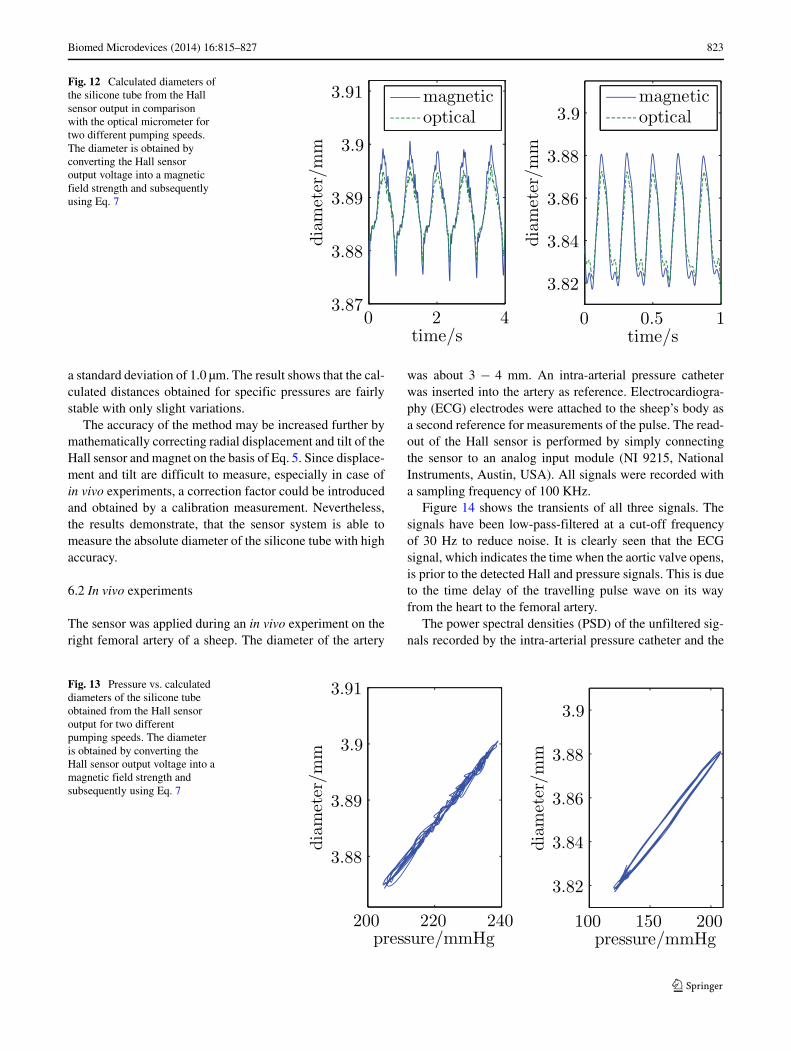
Figure 12 shows five pulses of the calculated diametersbased on the Hall sensor output together with the out-put from the optical micrometer for two different pumpingspeeds. The speed was 1.3 and 4.3 roller passes per second,respectively. The two different pumping speeds led to dif-ferent pressure ranges inside the tube. The mean deviationbetween the values obtained from the optical micrometerand from the Hall sensor for a two minutes measurement are1.8 µm and 4.9 µm with a standard deviation of 1.9 µm and5.5 µm for the two pumping speeds, respectively. These val-ues show, that the absolute diameter obtained from the Hallsensor differs only slightly from the diameter obtained bythe optical micrometer.
In Fig. 13, the diameter is plotted against pressure for thesame pulses as in Fig. 12, showing a nearly linear behav-ior for the lower pumping speed and a slight hysteresis forthe higher pumping speed. The hysteresis results from twoeffects: First, and most prominent is the viscoelastic behav-ior of the liquid-filled silicone tube which can be seen bycomparing the results obtained by the optical micrometerand pressure catheter (not shown here). Second, the weaknon-linear elastic and even small viscoelastic behavior ofthe implemented silicone. The hysteresis leads to a preci-sion of the detectable pressure variation of 7.4 mmHg forthe first and 12.1 mmHg for the second pumping speed.Whereas, these values also depend on the relative diametervariation, which is only 0.5 % and 1.5 %, respectively, forthe silicone tube used. The mean values in the two minutemeasurement range for the calculated distances at a pressurearound 205 mmHg are 3.875 and 3.879 mm, respectively.The mean deviation between the two values is 4.1 µm, with
Biomed Microdevices (2014) 16:815–827 823
Fig. 12 Calculated diameters ofthe silicone tube from the Hallsensor output in comparisonwith the optical micrometer fortwo different pumping speeds.The diameter is obtained byconverting the Hall sensoroutput voltage into a magneticfield strength and subsequentlyusing Eq. 7
a standard deviation of 1.0 µm. The result shows that the cal-culated distances obtained for specific pressures are fairlystable with only slight variations.
The accuracy of the method may be increased further bymathematically correcting radial displacement and tilt of theHall sensor and magnet on the basis of Eq. 5. Since displace-ment and tilt are difficult to measure, especially in case ofin vivo experiments, a correction factor could be introducedand obtained by a calibration measurement. Nevertheless,the results demonstrate, that the sensor system is able tomeasure the absolute diameter of the silicone tube with highaccuracy.
6.2 In vivo experiments
The sensor was applied during an in vivo experiment on theright femoral artery of a sheep. The diameter of the artery
was about 3 − 4 mm. An intra-arterial pressure catheterwas inserted into the artery as reference. Electrocardiogra-phy (ECG) electrodes were attached to the sheep’s body asa second reference for measurements of the pulse. The read-out of the Hall sensor is performed by simply connectingthe sensor to an analog input module (NI 9215, NationalInstruments, Austin, USA). All signals were recorded witha sampling frequency of 100 KHz.
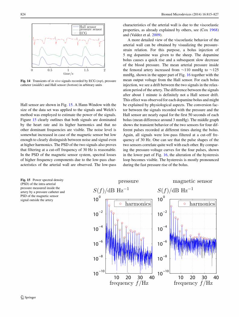
Figure 14 shows the transients of all three signals. Thesignals have been low-pass-filtered at a cut-off frequencyof 30 Hz to reduce noise. It is clearly seen that the ECGsignal, which indicates the time when the aortic valve opens,is prior to the detected Hall and pressure signals. This is dueto the time delay of the travelling pulse wave on its wayfrom the heart to the femoral artery.
The power spectral densities (PSD) of the unfiltered sig-nals recorded by the intra-arterial pressure catheter and the
Fig. 13 Pressure vs. calculateddiameters of the silicone tubeobtained from the Hall sensoroutput for two differentpumping speeds. The diameteris obtained by converting theHall sensor output voltage into amagnetic field strength andsubsequently using Eq. 7
824 Biomed Microdevices (2014) 16:815–827
Fig. 14 Transients of in vivo signals recorded by ECG (top), pressurecatheter (middle) and Hall sensor (bottom) in arbitrary units
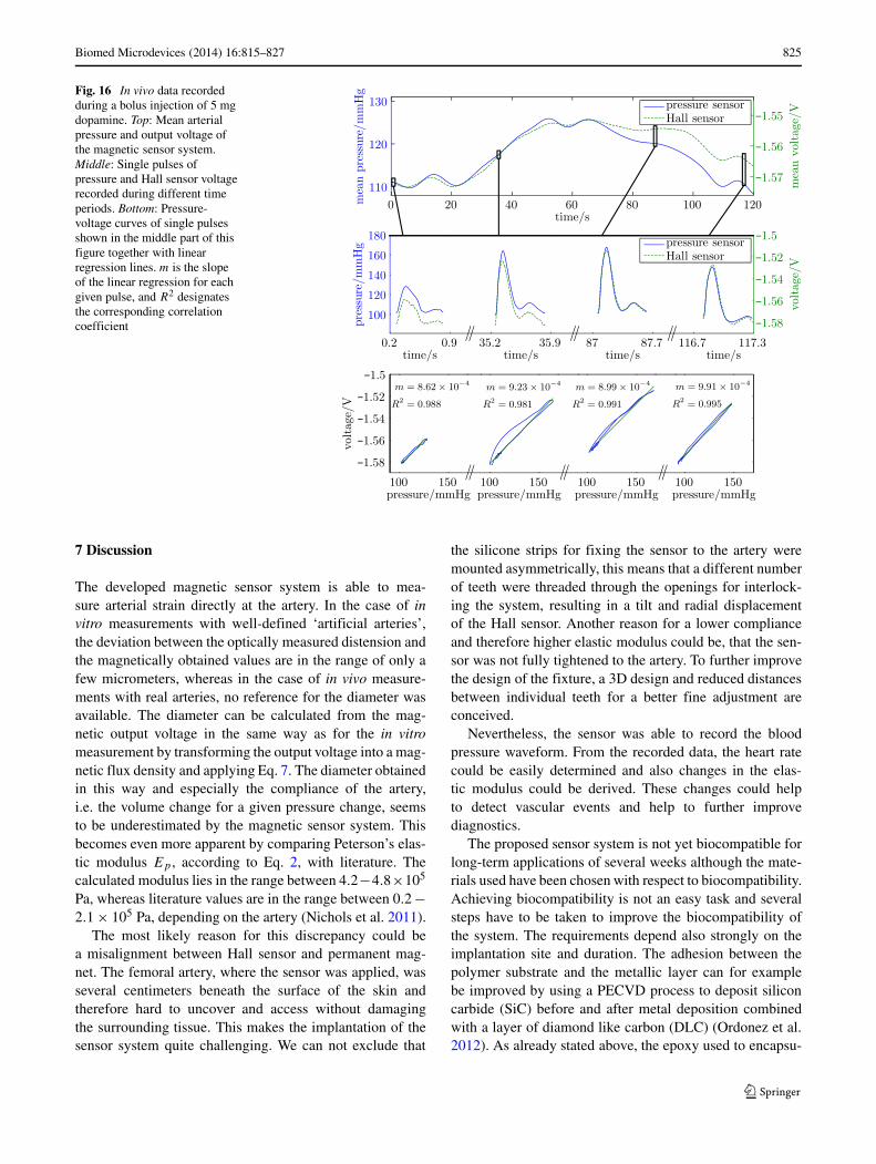
Hall sensor are shown in Fig. 15. A Hann-Window with thesize of the data set was applied to the signals and Welch’smethod was employed to estimate the power of the signals.Figure 15 clearly outlines that both signals are dominatedby the heart rate and its higher harmonics and that noother dominant frequencies are visible. The noise level issomewhat increased in case of the magnetic sensor but lowenough to clearly distinguish between noise and signal evenat higher harmonics. The PSD of the two signals also provesthat filtering at a cut-off frequency of 30 Hz is reasonable.In the PSD of the magnetic sensor system, spectral lossesof higher frequency components due to the low-pass char-acteristics of the arterial wall are observed. The low-pass
characteristics of the arterial wall is due to the viscoelasticproperties, as already explained by others, see (Cox 1968)and (Valdez et al. 2009).
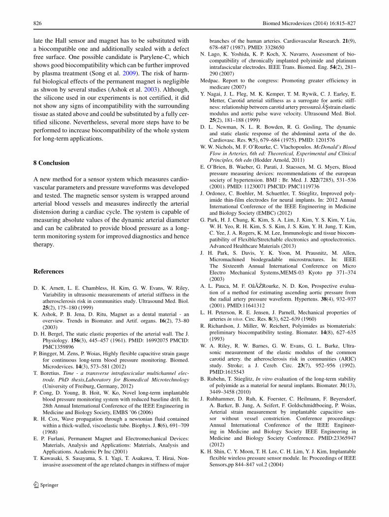
A more detailed view of the viscoelastic behavior of thearterial wall can be obtained by visualizing the pressure-strain relation. For this purpose, a bolus injection of5 mg dopamine was given to the sheep. The dopaminebolus causes a quick rise and a subsequent slow decreaseof the blood pressure. The mean arterial pressure insidethe femoral artery increased from ∼110 mmHg to ∼125mmHg, shown in the upper part of Fig. 16 together with themean output voltage from the Hall sensor. For each bolusinjection, we see a drift between the two signals in the relax-ation period of the artery. The difference between the signalsafter about 1 minute is definitely not a Hall sensor drift.This effect was observed for each dopamine bolus and mightbe explained by physiological aspects. The conversion fac-tor between the signals recorded with the pressure and theHall sensor are nearly equal for the first 50 seconds of eachbolus (mean difference around 3 mmHg). The middle graphshows the transient behavior of the two sensors for four dif-ferent pulses recorded at different times during the bolus.Again, all signals were low-pass filtered at a cut-off fre-quency of 30 Hz. One can see that the pulse shapes of thetwo sensors correlate quite well with each other. By compar-ing the pressure-voltage curves for the four pulses, shownin the lower part of Fig. 16, the alteration of the hysteresisloop becomes visible. The hysteresis is mostly pronouncedduring the fast pressure rise of the bolus.
Fig. 15 Power spectral density(PSD) of the intra-arterialpressure measured inside theartery by a pressure catheter andPSD of the magnetic sensorsignal outside the artery
Biomed Microdevices (2014) 16:815–827 825
Fig. 16 In vivo data recordedduring a bolus injection of 5 mgdopamine. Top: Mean arterialpressure and output voltage ofthe magnetic sensor system.Middle: Single pulses ofpressure and Hall sensor voltagerecorded during different timeperiods. Bottom: Pressure-voltage curves of single pulsesshown in the middle part of thisfigure together with linearregression lines. m is the slopeof the linear regression for eachgiven pulse, and R2 designatesthe corresponding correlationcoefficient
7 Discussion
The developed magnetic sensor system is able to mea-sure arterial strain directly at the artery. In the case of invitro measurements with well-defined ‘artificial arteries’,the deviation between the optically measured distension andthe magnetically obtained values are in the range of only afew micrometers, whereas in the case of in vivo measure-ments with real arteries, no reference for the diameter wasavailable. The diameter can be calculated from the mag-netic output voltage in the same way as for the in vitromeasurement by transforming the output voltage into a mag-netic flux density and applying Eq. 7. The diameter obtainedin this way and especially the compliance of the artery,i.e. the volume change for a given pressure change, seemsto be underestimated by the magnetic sensor system. Thisbecomes even more apparent by comparing Peterson’s elas-tic modulus Ep , according to Eq. 2, with literature. Thecalculated modulus lies in the range between 4.2−4.8×10⁵
Pa, whereas literature values are in the range between 0.2 −2.1 × 10⁵ Pa, depending on the artery (Nichols et al. 2011).
The most likely reason for this discrepancy could bea misalignment between Hall sensor and permanent mag-net. The femoral artery, where the sensor was applied, wasseveral centimeters beneath the surface of the skin andtherefore hard to uncover and access without damagingthe surrounding tissue. This makes the implantation of thesensor system quite challenging. We can not exclude that
the silicone strips for fixing the sensor to the artery weremounted asymmetrically, this means that a different numberof teeth were threaded through the openings for interlock-ing the system, resulting in a tilt and radial displacementof the Hall sensor. Another reason for a lower complianceand therefore higher elastic modulus could be, that the sen-sor was not fully tightened to the artery. To further improvethe design of the fixture, a 3D design and reduced distancesbetween individual teeth for a better fine adjustment areconceived.
Nevertheless, the sensor was able to record the bloodpressure waveform. From the recorded data, the heart ratecould be easily determined and also changes in the elas-tic modulus could be derived. These changes could helpto detect vascular events and help to further improvediagnostics.
The proposed sensor system is not yet biocompatible forlong-term applications of several weeks although the mate-rials used have been chosen with respect to biocompatibility.Achieving biocompatibility is not an easy task and severalsteps have to be taken to improve the biocompatibility ofthe system. The requirements depend also strongly on theimplantation site and duration. The adhesion between thepolymer substrate and the metallic layer can for examplebe improved by using a PECVD process to deposit siliconcarbide (SiC) before and after metal deposition combinedwith a layer of diamond like carbon (DLC) (Ordonez et al.2012). As already stated above, the epoxy used to encapsu-
826 Biomed Microdevices (2014) 16:815–827
late the Hall sensor and magnet has to be substituted witha biocompatible one and additionally sealed with a defectfree surface. One possible candidate is Parylene-C, whichshows good biocompatibility which can be further improvedby plasma treatment (Song et al. 2009). The risk of harm-ful biological effects of the permanent magnet is negligibleas shwon by several studies (Ashok et al. 2003). Although,the silicone used in our experiments is not certified, it didnot show any signs of incompatibility with the surroundingtissue as stated above and could be substituted by a fully cer-tified silicone. Nevertheless, several more steps have to beperformed to increase biocompatibility of the whole systemfor long-term applications.
8 Conclusion
A new method for a sensor system which measures cardio-vascular parameters and pressure waveforms was developedand tested. The magnetic sensor system is wrapped aroundarterial blood vessels and measures indirectly the arterialdistension during a cardiac cycle. The system is capable ofmeasuring absolute values of the dynamic arterial diameterand can be calibrated to provide blood pressure as a long-term monitoring system for improved diagnostics and hencetherapy.
References
D. K. Arnett, L. E. Chambless, H. Kim, G. W. Evans, W. Riley,Variability in ultrasonic measurements of arterial stiffness in theatherosclerosis risk in communities study. Ultrasound Med. Biol.25(2), 175–180 (1999)
K. Ashok, P. B. Jena, D. Ritu, Magnet as a dental material - anoverview. Trends in Biomater. and Artif. organs. 16(2), 73–80(2003)
D. H. Bergel, The static elastic properties of the arterial wall. The J.Physiology. 156(3), 445–457 (1961). PMID: 16992075 PMCID:PMC1359896
P. Bingger, M. Zens, P. Woias, Highly flexible capacitive strain gaugefor continuous long-term blood pressure monitoring. Biomed.Microdevices. 14(3), 573–581 (2012)
T. Boretius. Time - a transverse intrafascicular multichannel elec-trode. PhD thesis,Laboratory for Biomedical Microtechnology(University of Freiburg, Germany, 2012)
P. Cong, D. Young, B. Hoit, W. Ko, Novel long-term implantableblood pressure monitoring system with reduced baseline drift. In:28th Annual International Conference of the IEEE Engineering inMedicine and Biology Society, EMBS ’06 (2006)
R. H. Cox, Wave propagation through a newtonian fluid containedwithin a thick-walled, viscoelastic tube. Biophys. J. 8(6), 691–709(1968)
E. P. Furlani, Permanent Magnet and Electromechanical Devices:Materials, Analysis and Applications: Materials, Analysis andApplications. Academic Pr Inc (2001)
T. Kawasaki, S. Sasayama, S. I. Yagi, T. Asakawa, T. Hirai, Non-invasive assessment of the age related changes in stiffness of major
branches of the human arteries. Cardiovascular Research. 21(9),678–687 (1987). PMID: 3328650
N. Lago, K. Yoshida, K. P. Koch, X. Navarro, Assessment of bio-compatibility of chronically implanted polyimide and platinumintrafascicular electrodes. IEEE Trans. Biomed. Eng. 54(2), 281–290 (2007)
Medpac. Report to the congress: Promoting greater efficiency inmedicare (2007)
Y. Nagai, J. L. Fleg, M. K. Kemper, T. M. Rywik, C. J. Earley, E.Metter, Carotid arterial stiffness as a surrogate for aortic stiff-ness: relationship between carotid artery pressureaASstrain elasticmodulus and aortic pulse wave velocity. Ultrasound Med. Biol.25(2), 181–188 (1999)
D. L. Newman, N. L. R. Bowden, R. G. Gosling, The dynamicand static elastic response of the abdominal aorta of the do.Cardiovasc. Res. 9(5), 679–684 (1975). PMID: 1201576
W. W. Nichols, M. F. O’Rourke, C. Vlachopoulos. McDonald’s BloodFlow in Arteries, 6th ed: Theoretical, Experimental and ClinicalPrinciples, 6th edn (Hodder Arnold, 2011)
E. O’Brien, B. Waeber, G. Parati, J. Staessen, M. G. Myers, Bloodpressure measuring devices: recommendations of the europeansociety of hypertension. BMJ : Br. Med. J. 322(7285), 531–536(2001). PMID: 11230071 PMCID: PMC1119736
J. Ordonez, C. Boehler, M. Schuettler, T. Stieglitz, Improved poly-imide thin-film electrodes for neural implants. In: 2012 AnnualInternational Conference of the IEEE Engineering in Medicineand Biology Society (EMBC) (2012)
G. Park, H. J. Chung, K. Kim, S. A. Lim, J. Kim, Y. S. Kim, Y. Liu,W. H. Yeo, R. H. Kim, S. S. Kim, J. S. Kim, Y. H. Jung, T. Kim,C. Yee, J. A. Rogers, K. M. Lee, Immunologic and tissue biocom-patibility of Flexible/Stretchable electronics and optoelectronics.Advanced Healthcare Materials (2013)
J. H. Park, S. Davis, Y. K. Yoon, M. Prausnitz, M. Allen,Micromachined biodegradable microstructures. In: IEEEThe Sixteenth Annual International Conference on MicroElectro Mechanical Systems,MEMS-03 Kyoto pp 371–374(2003)
A. L. Pauca, M. F. OaAZRourke, N. D. Kon, Prospective evalua-tion of a method for estimating ascending aortic pressure fromthe radial artery pressure waveform. Hypertens. 38(4), 932–937(2001). PMID:11641312
L. H. Peterson, R. E. Jensen, J. Parnell, Mechanical properties ofarteries in vivo. Circ. Res. 8(3), 622–639 (1960)
R. Richardson, J. Miller, W. Reichert, Polyimides as biomaterials:preliminary biocompatibility testing. Biomater. 14(8), 627–635(1993)
W. A. Riley, R. W. Barnes, G. W. Evans, G. L. Burke, Ultra-sonic measurement of the elastic modulus of the commoncarotid artery. the atherosclerosis risk in communities (ARIC)study. Stroke; a J. Cereb. Circ. 23(7), 952–956 (1992).PMID:1615543
B. Rubehn, T. Stieglitz, In vitro evaluation of the long-term stabilityof polyimide as a material for neural implants. Biomater. 31(13),3449–3458 (2010)
J. Ruhhammer, D. Ruh, K. Foerster, C. Heilmann, F. Beyersdorf,A. Barker, B. Jung, A. Seifert, F. Goldschmidtboeing, P. Woias,Arterial strain measurement by implantable capacitive sen-sor without vessel constriction. Conference proceedings:Annual International Conference of the IEEE Engineer-ing in Medicine and Biology Society IEEE Engineering inMedicine and Biology Society Conference. PMID:23365947(2012)
K. H. Shin, C. Y. Moon, T. H. Lee, C. H. Lim, Y. J. Kim, Implantableflexible wireless pressure sensor module. In: Proceedings of IEEESensors,pp 844–847 vol.2 (2004)

Biomed Microdevices (2014) 16:815–827 827
J. S. Song, S. Lee, S. H. Jung, G. C. Cha, M. S. Mun,Improved biocompatibility of parylene-c films pre-pared by chemical vapor deposition and the subsequentplasma treatment. J. Appl. Polym. Sci. 112(6), 3677–3685(2009)
D. Steinhaus, D. W. Reynolds, F. Gadler, G. N. Kay, M. F. Hess,T. Bennett, F. T. C. Investigators, Implant experience with animplantable hemodynamic monitor for the management of symp-tomatic heart failure. Pacing Clin. Electrophysiol. 28(8), 747–753(2005)
M. Theodor, J. Fiala, D. Ruh, K. FAurster, C. Heilmann, F.Beyersdorf, Y. Manoli, H. Zappe, A. Seifert, Implantable
accelerometer system for the determination of blood pressureusing reflected wave transit time. Sensors Actuators A Phys. 206,151–158 (2014)
D. Valdez, H. T. Banks, M. A. Haider, D. Bia, Y. Zocalo, R. L.Armentano, M. S. Olufsen, Viscoelastic mmodel for passivearterial wall dynamics. Adv. Appl. Math. Mech. 1(2), 151–165(2009)
World Health Organization. WHO | global status report on noncom-municable diseases 2010 (2011)
B. Ziaie, K. Najafi, An implantable microsystem for tonometricblood pressure measurement. Biomed. Microdevices. 3(4), 285–292 (2001)