magnetoresistance in organic dirac fermion systemtakao.morinari/tm_alpha0119...effect of dirac cones...
TRANSCRIPT

Magnetoresistance in organic Dirac fermion system
Takao MorinariYukawa Institute for Theoretical Physics, Kyoto University
Workshop on Dirac Electron Systems 2011, National Institute for Materials Science, Jan.19, 2011
CollaboratorsTakami Tohyama (YITP)Takahiro Himura (YITP)
2011年4月8日金曜日

Outline
1. α-(BEDT-TTF)2I3 under pressure
2. Inter-layer magnetoresistanceZero energy Landau level effect
3. Inplane magnetoresistanceInter-Landau level transitionsElectron-electron interaction effect
4. Summary
2011年4月8日金曜日

α-(BEDT-TTF)2I3: Crystal Structure
Courtesy of N. Tajima (RIKEN)
C. Hotta, JPSJ 72, 840 (2003)
=BEDT-TTF: (C2H4S2)2C6S4
2011年4月8日金曜日
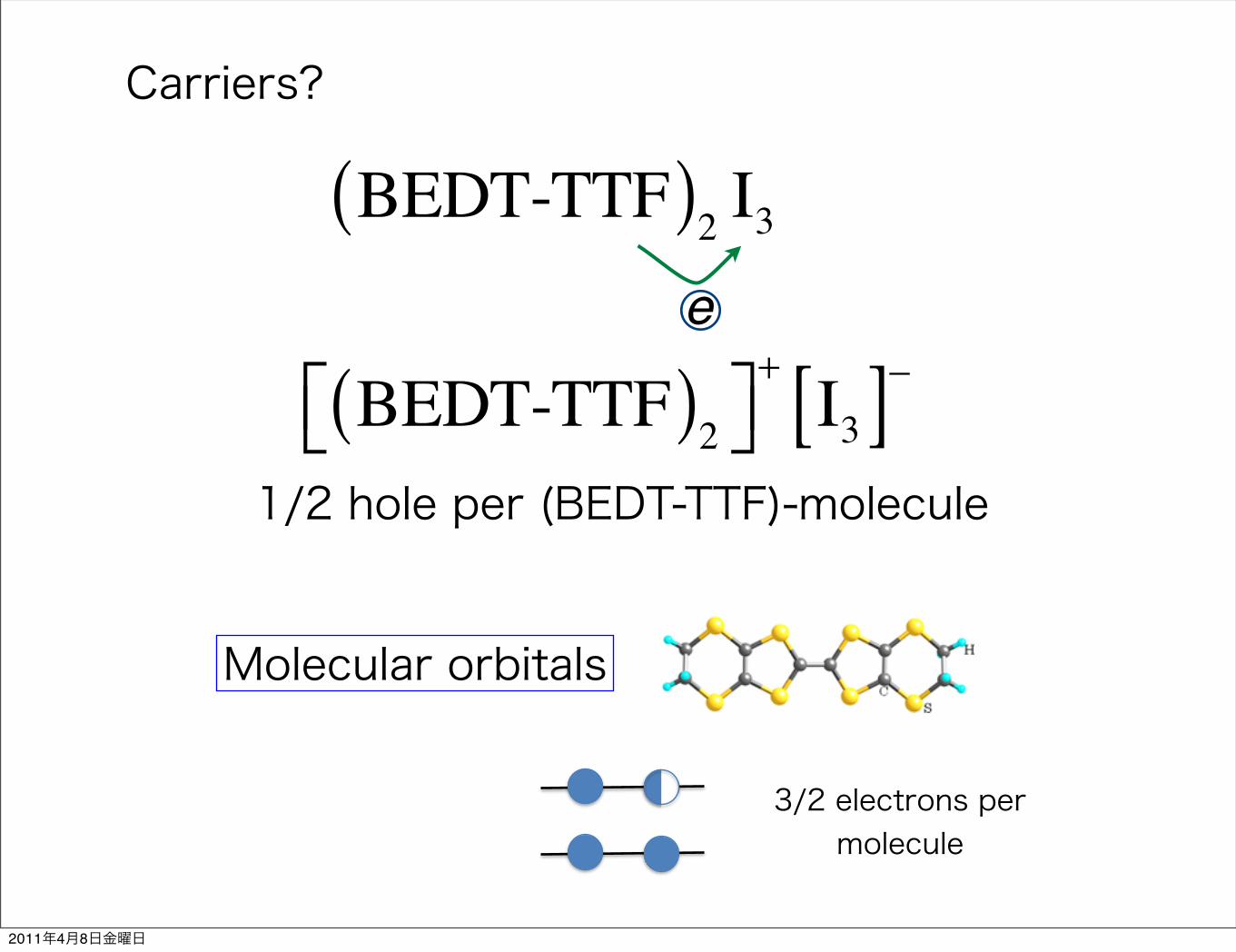
Carriers?
BEDT-TTF( )2 I3
BEDT-TTF( )2⎡⎣ ⎤⎦+I3[ ]−
e
1/2 hole per (BEDT-TTF)-molecule
Molecular orbitals
3/2 electrons per molecule
2011年4月8日金曜日

N.Tajima et al., J. Phys. Soc. Jpn. 75, 051010 (2006)
p=1.8GPa
Resistivity under pressure
H.Kino and H.Fukuyama, JPSJ 64, 1877 (1995) H.Seo, JPSJ 69, 805 (2000) Y.Takano et al., J. Phys. Chem. Solid 62, 393 (2001) R.Wojciechowski et al., PRB 67, 224105 (2003)
MI-transition
N. Tajima et al., Europhys. Lett. 80, 47002 (2007)
2011年4月8日金曜日

Tight-binding model analysis
tA P( ) = 1+ KAP( )tA 0( )R. Kondo, S. Kagoshima, and J. Harada,Rev. Sci. Instrum. 76, 093902 (2005)
Transfer integrals
A. Kobayashi et al., JPSJ 73, 3135 (2004)
S. Katayama, A. Kobayashi, and Y. Suzumura, JPSJ 75, 054705 (2006)
EF
H. Kino and T. Miyazaki, J. Phys. Soc. Jpn. 75, 034704 (2006)
S. Ishibashi et al, J. Phys. Soc. Jpn. 75 ,015005 (2006)
First principles calculation
2011年4月8日金曜日

Dirac fermions in α-(BEDT-TTF)2I3
• Bulk system
• The Fermi energy is at the Dirac point.
• The Dirac cone is tilted.
• The contact points move by changing pressure.
• Need to apply pressure.
2011年4月8日金曜日
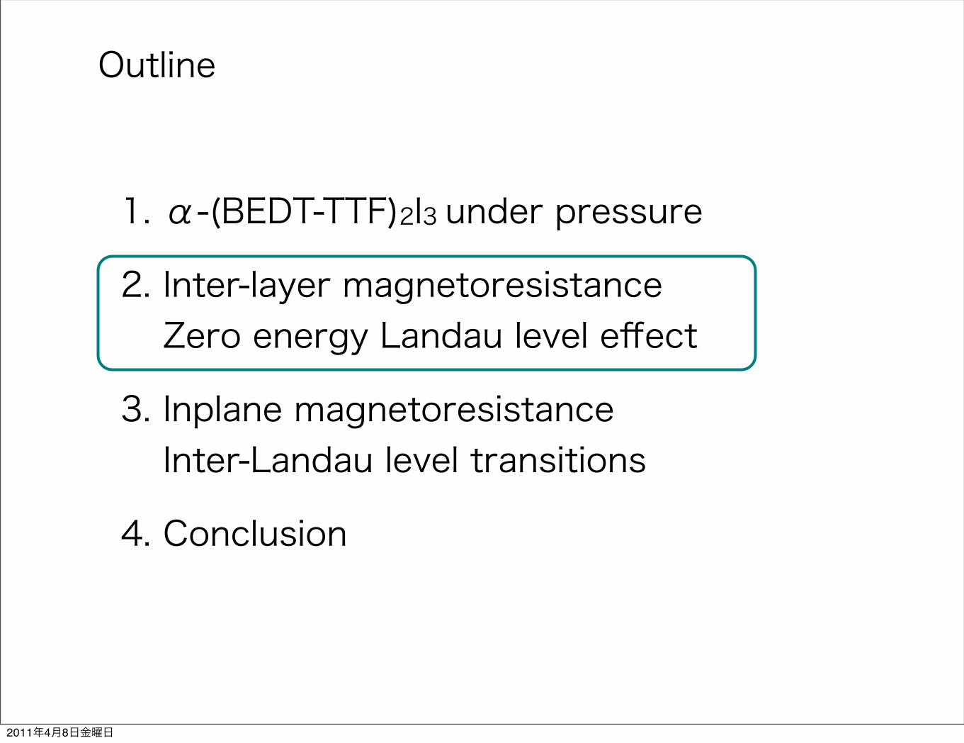
Outline
1. α-(BEDT-TTF)2I3 under pressure
2. Inter-layer magnetoresistanceZero energy Landau level effect
3. Inplane magnetoresistanceInter-Landau level transitions
4. Conclusion
2011年4月8日金曜日
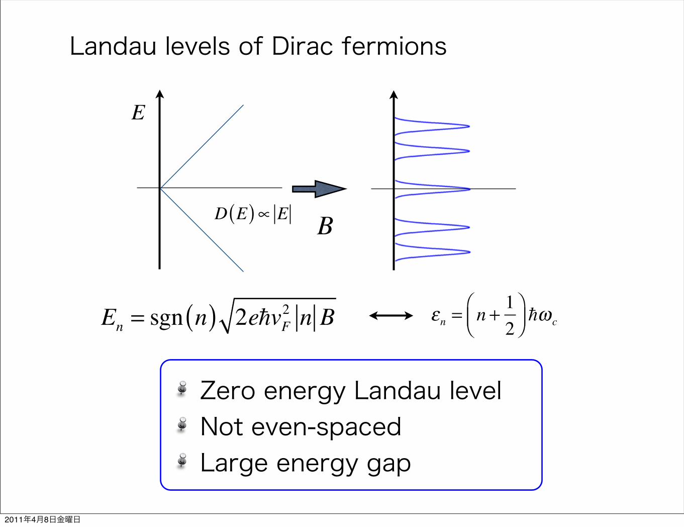
Landau levels of Dirac fermions
En = sgn n( ) 2evF2 n B εn = n + 1
2⎛⎝⎜
⎞⎠⎟ ω c
E
D E( )∝ E
Zero energy Landau levelNot even-spacedLarge energy gap
B
2011年4月8日金曜日

Interlayer magnetoresistance
!!
IB
High resistivity
B = 0
E
D E( ) D EF( )∝ B
T. Osada, JPSJ 77, 084711 (2008).
ρz ∝1B
EF
B ≠ 0
E
D E( )
Low resistivity
2011年4月8日金曜日

2. Interlayer magnetoresistance: Experiment
N.Tajima, S.Sugawara, R.Kato, Y.Nishio, and K.Kajita, Phys. Rev. Lett. 102, 176403 (2009).
Zero energy Landau level effect!
2011年4月8日金曜日

2. Interlayer magnetoresistance
Zero energy Landau level effect
Zeeman splitting?Tilted Dirac cone?Positive MR region?
N.Tajima et al., Phys. Rev. Lett. 102, 176403 (2009).
A. Kobayashi et al., JPSJ 73, 3135 (2004)
S. Katayama, A. Kobayashi, and Y. Suzumura, JPSJ 75, 054705 (2006)
2011年4月8日金曜日

Zeeman splitting?
N.Tajima et al., Phys. Rev. Lett. 102, 176403 (2009).
T. Osada, JPSJ 77, 084711 (2008).
E0 ±12gµBB g 2
Recently, Osada gave an analytical formula for inter-layer magnetoresistance in a multilayer Dirac fermionsystem as follows:
!zz !A
jBzj exp"# 12ec2$B2
x%B2y&@jBzj ' % B0
; (1)
where A ! "@3=2Ct2cce3 is a parameter that is consideredto be independent of the magnetic field if the system isclean. B0 is a fitting parameter, C is defined by C !R!0$E&$#df=dE&dE using the spectral density of the
zero-mode Landau level, and !0$E& satisfiesR!0$E&dE !
1 [22]. Note that only lattice constant c is a materialparameter.
Except for narrow regions around # ! 0( and 180(, thisformula can be simplified to !zz ! A=$jBzj% B0&. Usingthis formula and assuming B0 ! 0:7 T, we tried to fit thecurves in Fig. 1. This simple formula reproduces well boththe magnetic field dependence and the angle dependence ofthe magnetoresistance at magnetic fields above 0.5 T asshown by solid lines in Figs. 1(a) and 1(b), which eviden-ces the existence of zero-mode Landau carriers in$-$BEDT-TTF&2I3 at high pressures.
Here we briefly mention the origin of positive magneto-resistance around # ! 0( or 180(. In the magnetic field inthese directions, the Lorentz force works to bend the carriertrajectory to the direction parallel to the 2D plane. Itreduces the tunneling of carriers between neighboringlayers so that the positive magnetoresistance is observed.Note that the formula (1) for # ! 0( or 180( does notcorrectly evaluate the effect of the Lorentz force and, thus,loses its validity. The value of the resistance peak dependsweakly on the azimuthal angle. At 3 T, for example, theratio of the maximum value to the minimum value is lessthan 1.3. According to the calculation of interlayer mag-netoresistance by Morinari, Mimura, and Tohyama, theeffect of Dirac cones with highly anisotropic Fermi veloc-ity is averaged and gives rise to this small difference [25].
An apparent discrepancy of the data from the formula(1) is also seen at both low and high magnetic fields normalto the 2D plane, because the model is oversimplified.Equation (1) was derived based on the quantum limitpicture in which only the zero-mode Landau level is con-sidered. In fact, each Landau level has a finite width due toscattering. At a sufficiently low magnetic field, the zero-mode Landau level overlaps with other Landau levels. Insuch a region, the formula (1) loses its validity. We canrecognize this region in Fig. 1 below 0.2 T, where positivemagnetoresistance is observed. This critical magnetic fieldshifts to a lower field with decreasing temperature, asshown in Fig. 2(a).
The deviation of data in the high field region is muchmore serious. In this region, the resistance increases ex-ponentially with increasing field. This phenomenon isunderstood as follows.
In the above discussion, we did not consider the Zeemaneffect. The Zeeman effect, however, should be taken into
consideration because it has a significant influence on thetransport phenomena at low temperatures. In the presenceof a magnetic field, each Landau level is split into twolevels with energies EnLL ) !E, where !E ! %BB is theZeeman energy. This change in the energy structure givesrise to a change in the carrier density in Landau levels. Inparticular, the influence on the zero-mode carrier density isthe strongest, because the energy level is shifted from theposition of the Fermi energy. The value of the Fermidistribution function varies from f$EF& ! 1=2 to f$!E& !1="exp$!E=kBT& % 1'. At low temperatures where kBT <!E, this effect becomes important. It works to reduce thedensity of zero-mode carriers and, thus, increases theresistance.The Zeeman energy when B ! 1 T is about 1 K.
Therefore, in the experiment performed at 1 K, the devia-tion of experimental results from Eq. (1) is expected to startaround 1 T. This is confirmed in Fig. 2(a). At 1.8 K, forexample, the deviation is prominent in fields above 2 T.This critical field shifts to about 0.3 T at 0.06 K.A definite evidence showing that the anomalous increase
in the resistance at high field in Fig. 2(a) is due to theZeeman effect is given by examining the slopes of thecurves at high fields. In this region, the magnetic fielddependence of resistance is expressed as Rzz /exp$B=B1&, where B1 is a parameter that depends on tem-perature. B1 for T ! 1:8 K is estimated to be about 2.7 T.At 0.06 K, it decreases down to about 1.1 T. In Fig. 2(b), weplot the temperature dependence of B1. Above 1 K, the Tvs B1 curve is close to a line B1 ! kBT=%B. This is strongevidence that the Zeeman splitting of zero-mode Landaulevels is the origin of the resistance that obeys the expo-nential law as Rzz / exp$2%BB=2kBT&. In contrast, thebehavior of B1 below 1 K is understood in terms of thewidth of Landau levels. According to the theory of Osada,%BB=$@=&& * 1 at the magnetoresistance minimum [22].
FIG. 2. (a) Magnetic field dependence of interlayer resistancefor the magnetic field normal to the 2D plane at several tem-peratures from 0.06 to 9.6 K. (b) Temperature dependence of B1
when resistance is assumed to be Rzz / exp$B=B1&.(c) Temperature dependence of the width of Landau levels(2@=&).
PRL 102, 176403 (2009) P HY S I CA L R EV I EW LE T T E R Sweek ending1 MAY 2009
176403-3
Γ ~ 1K2011年4月8日金曜日

Tilted Dirac cone?
En = tilt param.( )× nBTM, T.Himura, and T. Tohyama,
J. Phys. Soc. Jpn. 78, 023704 (2009).
Landau levels
M. O. Goerbig, J.-N. Fuchs, G. Montambaux, and F. Piechon, Phys. Rev. B 78, 045415 (2008).
H =HDirac + v0kx
H =v0xkx + v0
yky + vzxkx + vz
yky vxxkx + vx
yky − i vyxkx + vy
yky( )vxxkx + vx
yky + i vyxkx + vy
yky( ) v0xkx + v0
yky − vzxkx − vz
yky
⎛
⎝
⎜⎜
⎞
⎠
⎟⎟
A.Kobayashi et al., J. Phys. Soc. Jpn. 76, 034711 (2007).
2011年4月8日金曜日

Effect of tilted Dirac cone
Tilt direction
k-space
B
B
Large resistivity
Low resistivityλ = 1− v0
vD
⎛⎝⎜
⎞⎠⎟
2
2011年4月8日金曜日

Positive MR?
N.Tajima, S.Sugawara, R.Kato, Y.Nishio, and K.Kajita, Phys. Rev. Lett. 102, 176403 (2009).
En = C nB
C = 10K/T1/2
E0 E1
E
T.M. and T. Tohyama, J. Phys. Soc. Jpn. 79, 044708 (2010).
ψ n
ψ ′n
j-th layer
j+1-th layer
ψ ′n ψ n ≠ 0
N.Tajima et al., Phys. Rev. Lett. 102, 176403 (2009).
2011年4月8日金曜日

Tmax = ΔE / kB
B T[ ]
T-dep. of positive MRS.Sugawara, M.Tamura, N.Tajima, R.Kato, M.Sato, Y.Nishio, and K.Kajita,
J. Phys. Soc. Jpn. 79, 113704 (2010)
vF = 2.4 ×10⁴m/s
C = 9.3K/T1/2
C B − gµBB
T K[ ]
ΔRz
2011年4月8日金曜日

Outline
1. α-(BEDT-TTF)2I3 under pressure
2. Theories suggesting Dirac fermion spectrum.
3. Inter-layer magnetoresistanceZero energy Landau level effect
4. Inplane magnetoresistanceInter-Landau level transitions
5. Conclusion
2011年4月8日金曜日

4. In-plane MR: Experiment
N.Tajima, S.Sugawara, M.Tamura, Y.Nishio, and K.Kajita, J. Phys. Soc. Jpn. 75, 051010 (’06).
2011年4月8日金曜日

4. In-plane magnetoresistance
!!
Interlayer MR
Same Landau levels
What makes difference from the interlayer MR?
Different Landau levels
Reflect the Landau level structure
Inplane MR
2011年4月8日金曜日
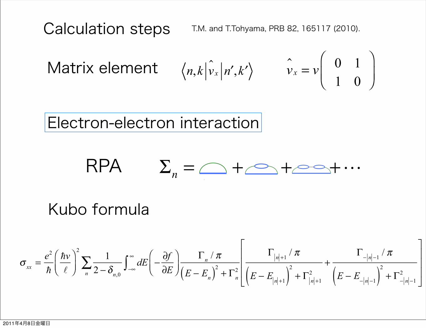
Σn = + + +
Calculation steps
σ xx =e2
v
⎛⎝⎜
⎞⎠⎟
21
2 − δn,0dE
−∞
∞
∫ −∂f∂E
⎛⎝⎜
⎞⎠⎟
Γn / π
E − En( )2 + Γn2n
∑Γ n +1 / π
E − E n +1( )2 + Γ n +12
+Γ
− n −1 / π
E − E− n −1( )2 + Γ
− n −12
⎡
⎣
⎢⎢⎢
⎤
⎦
⎥⎥⎥
v x = v 0 11 0
⎛
⎝⎜⎞
⎠⎟Matrix element n,k v x ′n , ′k
Kubo formula
Electron-electron interaction
RPA
T.M. and T.Tohyama, PRB 82, 165117 (2010).
2011年4月8日金曜日

Self-energy formulaΣn,kRPA ω + iδ( ) = − 1
πe−12q2B
2 n< !n> ! B2 q2
2⎛
⎝⎜⎞
⎠⎟
n− ′n
Ln<n− ′n B
2 q2
2⎛
⎝⎜⎞
⎠⎟⎡
⎣⎢⎢
⎤
⎦⎥⎥
2
Vqq, ′n∑
× dε−∞
∞
∫ Im 1εq ε( )⎡
⎣⎢⎢
⎤
⎦⎥⎥
f E ′n( ) + n ε( )ω + iδ − E ′n + ε
Im 1εq ε + iδ( )⎡
⎣⎢⎢
⎤
⎦⎥⎥=
D2Vq
1− D1Vq( )2 + D2Vq( )2
D1 = − 12π B
2 e−12q2B
2 n< !n> ! B2 q2
2⎛
⎝⎜⎞
⎠⎟
n1−n2
Ln<n1−n2 B
2 q2
2⎛
⎝⎜⎞
⎠⎟⎡
⎣⎢⎢
⎤
⎦⎥⎥
2
n1 ,n2 ,s∑ P
f En2 ,s( )− f En1 ,s( )ε − En2 ,s + En1 ,s
D2 =12 B
2 e−12q2B
2 n< !n> ! B2 q2
2⎛
⎝⎜⎞
⎠⎟
n1−n2
Ln<n1−n2 B
2 q2
2⎛
⎝⎜⎞
⎠⎟⎡
⎣⎢⎢
⎤
⎦⎥⎥
2
n1 ,n2 ,s∑
× f En2 ,s( )− f En1 ,s( )⎡⎣
⎤⎦δ ε − En2 ,s + En1 ,s( )
− ImΣn
RPA En + iδ( ) = ΓnC
E
!nC
En2011年4月8日金曜日

Landau level broadening
2BvFB
= 10KT−1/2
= 300
T.M. and T.Tohyama, PRB 82, 165117 (2010).
energy gap between the zero-energy Landau level and the!n!=1 Landau level. Reflecting this fact, !n
C decreases as weincrease the magnetic field because the Landau-level energygaps increase.
Figure 1"b# shows !nC for graphene where we take
"=2.5 for the dielectric constant19 and $2 /B#v /!B=400 K /T!1/2 for the Landau-level structure parameter.4 Al-though the temperature dependence of !n
C is different fromFig. 1"a# because of the parameter differences, it is commonthat the n=0 Landau-level component behaves differently ascompared with the n=0 Landau level. Since the Landau-level energy gaps between the n=0 Landau level and the n=1 Landau level for graphene is about 1000 K, the value of!0
C is negligible in the temperature range shown in Fig. 1"b#.This result is consistent with the experiment20 suggesting
that the zero-energy Landau level is quite sharp in shapecompared with the other Landau levels. Compared to$-"BEDT-TTF#2I3, the almost temperature independent re-gion extended until %120 K. This is because the Landau-level energy spacing in graphene is larger than that in$-"BEDT-TTF#2I3. As shown in Fig. 1"b# the interaction ef-fect on !n
C is negligible for T%100 K due to the large sepa-ration between the Landau levels.
IV. IN-PLANE MAGNETORESISTANCE
Now we compute the in-plane longitudinal conductivity&xx using the Kubo formula21
&xx =e2
# &#v!B'2
(n,&
Cn)!'
'
dE&!! f
!E'(
!n/)"E ! En, + !n
2* !!n!+1/)"E ! E!n!+1, + !!n!+1
2
+!!!n!!1/)
"E ! E!!n!!1, + !!!n!!12 + , "10#
where f is the Fermi distribution function and the Zeemanenergy splitting is included as En,&=En+g*B&B /2. Here *Bis the Bohr magnetron and we set g=2. The scattering rate isassumed to be !n=!0+!n
C, where !0 is associated with im-purity scattering. In the following calculation we take !0=2 K that was estimated from analysis of the interlayermagnetoresistance data13 at low temperatures.16 To reducethe numerical computation time we use Páde approximantsfor the temperature dependence of !n
C. For Landau levelswith n"0 we used the same Páde approximant for !1
C be-cause !n
C with n"0 behave similarly as shown in Fig. 1"a#.Figure 2 shows the in-plane resistivity, +xx=1 /&xx for dif-
ferent magnetic fields. Note that &xy =0 because the Fermienergy is at the Dirac point. Here we assume particle-holesymmetry so that the Fermi energy is fixed to the Dirac pointeven at finite temperatures. The minima appear around Tmin,100 K. These minima appear because of the onset of theLandau-level splitting effect: The Landau levels with !n!%10 are well separated each other. But those separations areunimportant for T%100 K because of the temperaturebroadening effect due to the derivative of the Fermi distribu-tion function in Eq. "10#. For T,100 K, Landau levels with!n!-10 are almost continuously distributed because !En+1!En!%!n+1+!n. For T%100 K, we find that !E10.1!E10!,!10.1+!10 from the temperature dependence of !n
C. So theLandau level splitting effect appears for T%100 K. Wecomputed &xx without including !n
C, and confirmed that thetemperature dependence of +xx for T,100 K mainly arisesfrom the temperature dependence of !n
C.
0
0.5
1
1.5
2
2.5
0 20 40 60 80 100 120 140 160 180 200
! nC(K)
T (K)
n=0n=1n=2n=3n=5
(a)
0
0.5
1
1.5
2
2.5
3
0 20 40 60 80 100 120 140 160 180 200
!Cn(K)
T (K)
n=0n=1n=2n=3n=5
(b)
FIG. 1. "Color online# "a# Temperature dependence of !nC at
B=10 T for different Landau levels with /=0.1 for$-"BEDT-TTF#2I3. "b# Temperature dependence of !n
C at B=10 Tfor graphene.
10-1
100
101
102
103
1 10 100
! xx/
! 0
T (K)
B=10.0TB=15.0TB=20.0T
FIG. 2. "Color online# The in-plane resistivity for different mag-netic fields with !0=2 K. The normalization parameter +0 is takenas +0=+xx"100 K# at B=10 T to compare with the experiment inRef. 5.
THEORY OF IN-PLANE MAGNETORESISTANCE IN TWO-… PHYSICAL REVIEW B 82, 165117 "2010#
165117-3
2011年4月8日金曜日

Experiment and theory
N.Tajima, S.Sugawara, M.Tamura, Y.Nishio, and K.Kajita, J. Phys. Soc. Jpn. 75, 051010 (’06).
10-1
100
101
102
103
1 10 100xx
/0
T[K]
B=10.0TB=15.0TB=20.0T
T.M. and T.Tohyama, PRB 82, 165117 (2010).
2011年4月8日金曜日

Interpretation
D. Valley splitting
DOS
E
T
A. B is negligible.AB
CD
B. Landau level splitting effect
E1 − E0C.
plasmon modes
N.Tajima, S.Sugawara, M.Tamura, Y.Nishio, and K.Kajita, J. Phys. Soc. Jpn. 75, 051010 (’06).
2011年4月8日金曜日

Summary
α-(BEDT-TTF)2I3 under pressure
is a Dirac fermion system.
Magnetoresistance experiments are well described by the Dirac fermions.
Inter-layer MR
In-plane MR
Zero-energy Landau levelTilted cone can be detected.
Reflect the Landau level structure
2011年4月8日金曜日

End
2011年4月8日金曜日
Appendix
2011年4月8日金曜日

Charge Disproportionation
A. Kobayashi, S. Katayama, Y. Suzumura, and H. Fukuyama, J. Phys. Soc. Jpn. 76, 034711 (2007).
Mean field calculation result
Vc = 0.17x, Vp = 0.05x,U = 0.4x
2011年4月8日金曜日

Landau level broadening
energy gap between the zero-energy Landau level and the!n!=1 Landau level. Reflecting this fact, !n
C decreases as weincrease the magnetic field because the Landau-level energygaps increase.
Figure 1"b# shows !nC for graphene where we take
"=2.5 for the dielectric constant19 and $2 /B#v /!B=400 K /T!1/2 for the Landau-level structure parameter.4 Al-though the temperature dependence of !n
C is different fromFig. 1"a# because of the parameter differences, it is commonthat the n=0 Landau-level component behaves differently ascompared with the n=0 Landau level. Since the Landau-level energy gaps between the n=0 Landau level and the n=1 Landau level for graphene is about 1000 K, the value of!0
C is negligible in the temperature range shown in Fig. 1"b#.This result is consistent with the experiment20 suggesting
that the zero-energy Landau level is quite sharp in shapecompared with the other Landau levels. Compared to$-"BEDT-TTF#2I3, the almost temperature independent re-gion extended until %120 K. This is because the Landau-level energy spacing in graphene is larger than that in$-"BEDT-TTF#2I3. As shown in Fig. 1"b# the interaction ef-fect on !n
C is negligible for T%100 K due to the large sepa-ration between the Landau levels.
IV. IN-PLANE MAGNETORESISTANCE
Now we compute the in-plane longitudinal conductivity&xx using the Kubo formula21
&xx =e2
# &#v!B'2
(n,&
Cn)!'
'
dE&!! f
!E'(
!n/)"E ! En, + !n
2* !!n!+1/)"E ! E!n!+1, + !!n!+1
2
+!!!n!!1/)
"E ! E!!n!!1, + !!!n!!12 + , "10#
where f is the Fermi distribution function and the Zeemanenergy splitting is included as En,&=En+g*B&B /2. Here *Bis the Bohr magnetron and we set g=2. The scattering rate isassumed to be !n=!0+!n
C, where !0 is associated with im-purity scattering. In the following calculation we take !0=2 K that was estimated from analysis of the interlayermagnetoresistance data13 at low temperatures.16 To reducethe numerical computation time we use Páde approximantsfor the temperature dependence of !n
C. For Landau levelswith n"0 we used the same Páde approximant for !1
C be-cause !n
C with n"0 behave similarly as shown in Fig. 1"a#.Figure 2 shows the in-plane resistivity, +xx=1 /&xx for dif-
ferent magnetic fields. Note that &xy =0 because the Fermienergy is at the Dirac point. Here we assume particle-holesymmetry so that the Fermi energy is fixed to the Dirac pointeven at finite temperatures. The minima appear around Tmin,100 K. These minima appear because of the onset of theLandau-level splitting effect: The Landau levels with !n!%10 are well separated each other. But those separations areunimportant for T%100 K because of the temperaturebroadening effect due to the derivative of the Fermi distribu-tion function in Eq. "10#. For T,100 K, Landau levels with!n!-10 are almost continuously distributed because !En+1!En!%!n+1+!n. For T%100 K, we find that !E10.1!E10!,!10.1+!10 from the temperature dependence of !n
C. So theLandau level splitting effect appears for T%100 K. Wecomputed &xx without including !n
C, and confirmed that thetemperature dependence of +xx for T,100 K mainly arisesfrom the temperature dependence of !n
C.
0
0.5
1
1.5
2
2.5
0 20 40 60 80 100 120 140 160 180 200
! nC(K)
T (K)
n=0n=1n=2n=3n=5
(a)
0
0.5
1
1.5
2
2.5
3
0 20 40 60 80 100 120 140 160 180 200
!Cn(K)
T (K)
n=0n=1n=2n=3n=5
(b)
FIG. 1. "Color online# "a# Temperature dependence of !nC at
B=10 T for different Landau levels with /=0.1 for$-"BEDT-TTF#2I3. "b# Temperature dependence of !n
C at B=10 Tfor graphene.
10-1
100
101
102
103
1 10 100
! xx/
! 0
T (K)
B=10.0TB=15.0TB=20.0T
FIG. 2. "Color online# The in-plane resistivity for different mag-netic fields with !0=2 K. The normalization parameter +0 is takenas +0=+xx"100 K# at B=10 T to compare with the experiment inRef. 5.
THEORY OF IN-PLANE MAGNETORESISTANCE IN TWO-… PHYSICAL REVIEW B 82, 165117 "2010#
165117-3
α-(BEDT-TTF)2I3 Graphene
2BvFB
= 400KT−1/2
2BvFB
= 10KT−1/2
= 2.5 = 300
T.M. and T.Tohyama, PRB 82, 165117 (2010).
2011年4月8日金曜日
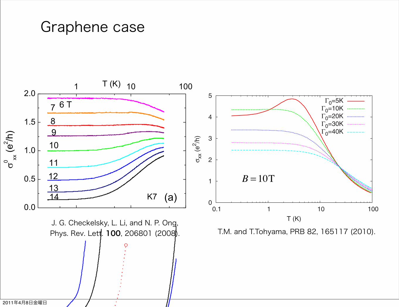
Graphene case
The appearance of a minimum at a characteristic tempera-ture Tmin in the in-plane magnetoresistance suggests that Tminis a crossover temperature from the interaction dominant re-gime to the almost noninteracting regime: for T!Tmin, theLandau-level broadening smears out the Landau-level energyspectrum. In this regime, the Landau-level spacing is unim-portant, and the electron-electron interaction, which requiresthe excitations from one Landau level to higher Landau lev-els, plays an important role. By contrast for T"Tmin, theLandau-level broadening is less than the Landau-level spac-ing. Thus, the excitations from one Landau level to higherLandau levels are suppressed. The characteristic temperatureTmin depends on #, v, and B. Although there is no simpleanalytical formula for Tmin, one can determine Tmin from thein-plane magnetoresistance measurement. The same analysiscan be applied to the surface states of three dimensional to-pological insulators.22,23
With decreasing the temperature from !100 K the resis-tivity increases because the number of Landau levels contrib-uting to $xx decreases. Below 10 K a narrow plateau regionappears. If we compute %xx omitting the Zeeman energy split-ting, we have a peak instead of the plateau and %xx ap-proaches a universal curve that is independent of the mag-netic field. The peak position is scaled by "B. So thepresence of the plateau is associated with the Landau-levelsplitting between n=0 and n= &1. Namely, including theZeeman energy splitting transforms the peak to the plateau.For T"2'0, %xx turns to increase again, and then %xx ap-proaches a temperature-independent value. We note that for aconventional parabolic dispersion case %xx monotonically in-creases with decreasing the temperature because the Landaulevels are equally spaced.
All features stated above are consistent with theexperiment5 except for T"2'0. In the experiment, %xx doesnot approach a temperature-independent value for T"1 Kbut increases further with decreasing temperature changingthe slope at a characteristic temperature Texp. This behaviorsuggests that there is an another Landau level splitting prob-ably associated with valley splitting. In Ref. 24, a Kosterlitz-Thouless transition scenario was proposed. We will investi-gate this point further in a future publication.
Now we comment on the tilt of the Dirac cone. In(-#BEDT-TTF$2I3, theoretical calculations suggest that theDirac cone is tilted.8 In the presence of the tilt of the Diraccone, the Landau-level wave functions are deformed10 thatleads to anisotropy of the resistivity. However, the features ofthe in-plane magnetoresistance are unaffected by the tilt. Thetemperature dependence of the in-plane magnetoresistance isdetermined by the Landau-level structure. Since the tilt ofthe Dirac cone just leads to a modification of the overallfactor of the Landau-level energies and does not affect theLandau-level structure qualitatively,10 the tilt is unimportantfor the temperature dependence of the in-plane magnetore-sistance.
Using the theory, we are able to understand some resultsabout $xx in graphene. Figure 3 shows $xx for different '0 at
B=10 T. We computed $xx for B!10 T as well #notshown$ and found similar behaviors. The results with '0!10 K are in good agreement with the experiment25 for B"8 T. Experimentally '0 is estimated19 as '0!30 K. Forclean samples with '0, we should observe a peak associatedwith the Zeeman splitting around T=2'0!)BB. For '0=5 K, the peak appears around 2'0!)BB!3 K as shownin Fig. 3. In the experiment reported in Ref. 25, $xx decreasesat low temperatures for B!10 T. To understand this behav-ior, we need to assume that a valley splitting occurs as dis-cussed in the literature.26
V. CONCLUSION
In conclusion, we have investigated the in-plane resistiv-ity of Dirac fermions under magnetic field. We have includedthe Landau-level structure, the Zeeman energy splitting, andthe Coulomb interaction effect between Dirac fermions. TheCoulomb interaction plays an important role at high tempera-tures, where Dirac fermions are excited from the zero-energyLandau level. We found that the n=0 Landau level behavesdifferently compared to the other Landau levels. The featuresobserved in (-#BEDT-TTF$2I3 are consistent with our resultexcept for T"1 K where a valley splitting may play animportant role. This theory has also been applied tographene. We have found a consistent behavior with an ex-isting experimental data and have predicted the presence of apeak structure of conductivity in clean samples.
ACKNOWLEDGMENTS
We would like to thank N. Tajima for helpful discussions.This work was supported by KAKENHI #Grant No.21740252$, the Global COE Program “The Next Generationof Physics, Spun from Universality and Emergence,” andYukawa International Program for Quark-Hadron Sciences atYITP.
0
1
2
3
4
5
0.1 1 10 100
! xx
(e2 /h
)
T (K)
"0=5K"0=10K"0=20K"0=30K"0=40K
FIG. 3. #Color online$ The temperature dependence of $xx forgraphene for different '0 at B=10 T.
TAKAO MORINARI AND TAKAMI TOHYAMA PHYSICAL REVIEW B 82, 165117 #2010$
165117-4
rapidly approaching a field-induced crossover (or transi-tion) to a state with very large R0.
In light of the importance of V0, it is instructive to seehow the profile of R0 vs H varies between samples.Figure 3(c) compares the results in K7, K18 and K22 atT ! 0:3 K. In K18, where V0 (20 V) is quite large, thedivergence in R0"H# becomes noticeable only in fields
above 14 T. Conversely, in K22 for which V0 ($0:6 V) isslightly smaller than in K7, R0 diverges at field scalessmaller than in K7. (Above H ! 12 T, the curve of R0 inK22 rises to very large values, reaching 9 M! at 33 T.However, for R0 > 0:5 M!, it is plagued by breaks inslope and oscillations, suggestive of severe self-heating).
From the trend, it is clear that the divergence in R0 isshifted to ever higher fields as V0 increases. Referring backto Fig. 2(c), we now see that the strong suppression ofR0"14# in samples with large V0 simply reflects the shift ofthe divergence to larger H. These results underscore theimportance of choosing samples with jV0j< 1 V for in-vestigating the intrinsic properties of the Dirac-point. InK7, we also checked that R0 measured by varying Vg atfixed H or by varying H in fixed Vg agree numerically.
The variation of R0"T;H# in K7 is conveniently repre-sented in a contour plot in the T-H plane (Fig. 4). Below%2 K, the contour lines are horizontal, which implies thatR0 is unchanged if the sample is cooled in fixed H. Thisprovides evidence that !res involves gapless excitations.However, if T is fixed, R0 rises steeply with H, implyingproximity to the large-R0 state (deep-red region). When asystem approaches the large-resistance state, its resistivitygenerally diverges as T ! 0, as a result of either stronglocalization (variable-range hopping) or the opening of amobility gap (weak localization is not relevant here be-cause of the intense H). In both cases, decreasing T reducesthe conductance because the itinerant states are severelydepopulated. Hence, the pattern in Fig. 4(a) is most un-usual. The gaplessness of !res suggests that, below 2 K,these excitations are protected from the effects of changingT. Paradoxically, they are not protected from an increasingH, which reduces the current carried at an exponential rate.
One way to distinguish theories is by how the fourfolddegeneracy in the n ! 0 LL is lifted. In the theory inRefs. [13,16], the exchange energy lifts the spin degener-acy (but nominally not the valley degeneracy) in the bulk.At the edge, lifting of the valley degeneracy creates a pairof counter-propagating edge states. In the sample shown inRef. [13], the slight increase in R0 (threefold at 33 T) wasexplained by increased scattering between the edge states.However, in our data, this mild change with H is actuallyseen only in samples with V0 > 30 V. Samples with verysmall jV0j [K22 and K7 in Fig. 3(c)] are in a radicallydifferent category. In large H, the divergence in R0 (whichreaches 9 M! at 33 T in K22) is far too large to beexplained by counter-propagating edge states. Instead,our results imply a high-field ordered state consistentwith the quantum Hall insulator [7–10].
The scenario is suggested by the form of R0"H#, whichfits very well to the form R0 % ""h#2, where the correlationlength " has the Kosterlitz-Thouless (KT) dependence
"KT % exp"b=!!!!!!!!!!!!1$ h
p#; "h ! H=H0#; (2)
with H replacing T. Plotting lnR0 vs!!!!!!!!!!!!1$ h
p, we find that
the high-field portion becomes linear [Fig. 4(b)] when H0
FIG. 3 (color online). The T dependence of !0xx in K7 ( !
L=wR0) and the H dependence of R0 at low temperature. Panel ashows curves of !0
xx vs log10T with H fixed at 6–14 T. For H >8 T, the gap " causes !0
xx to decrease markedly until saturationat the residual value !res occurs below 2 K. Panel (b) displays thesteep increase in R0 vs H in K7 at selected T. At 0.3 K, R0
appears to diverge at a field near 18 T [see Fig. 4(b)]. Panel (c)compares the R0"H# profiles in Samples K7, K18, and K22. Insample K18 (V0 ! 20 V), the divergence in R0 becomes appar-ent only above 14 T, whereas in K22 (V0 ! $0:6 V) R0 starts todiverge at fields lower than in K7. In K7, we have plotted R0
values measured by sweeping Vg at fixed H (solid symbols) withR0 measured by sweeping H with V0
g fixed at 0 (solid curve), toshow consistency.
PRL 100, 206801 (2008) P H Y S I C A L R E V I E W L E T T E R S week ending23 MAY 2008
206801-3
J. G. Checkelsky, L. Li, and N. P. Ong, Phys. Rev. Lett. 100, 206801 (2008). T.M. and T.Tohyama, PRB 82, 165117 (2010).
B = 10T
2011年4月8日金曜日