magnetoresistance phenomena and...
TRANSCRIPT

JOSE MARIA DE TERESA
(CSIC - UNIVERSIDAD DE ZARAGOZA, SPAIN)
MAGNETORESISTANCE PHENOMENA AND RELATED EFFECTS
-INTRODUCTION TO MAGNETORESISTANCE (MR)
-LORENTZ MR, ANISOTROPIC MR, HALL EFFECT, SPIN-DISORDER MR AND COLOSSAL MR
-GIANT MR
-TUNNEL MR
-OTHER MAGNETORESISTIVE EFFECTS
-APPLICATIONS OF MAGNETORESISTIVE DEVICES
*EXCHANGE-BIAS FOR SPIN VALVES
*MAGNETIC RANDOM ACCESS MEMORIES
Cluj school, September 2007

SPINTRONICS / MAGNETOELECTRONICS
Cluj school, September 2007

INTRODUCTION TO
MAGNETORESISTANCE:
PRELIMINARY CONCEPTS
Cluj school, September 2007

GEOMETRIES FOR THE MEASUREMENT OF RESISTANCE
Bulk samples are normally measured in bar-shaped geometry and four-point linear
contacts. Resistivity can be determined.
I+ I-V+ V-
1 2 3 4
d
S
I
VF
4,1
3,2=ρ (F can be approximated to1 in most of the situations)
*Four-contact measurements eliminate the contactand lead resistances. One should be carefulregarding offset signals such as thermoelectriceffects, electronic offsets, electromotive forces, whichcan be minimised by current inversion in d.c. measurements or using a.c. measurements:
*R=(R1+R2)/2 with R1= I1-4/V2-3 and R2=I4-1/V3-2
*Roffset=(R1-R2)/2
Typical sizeis millimetric
ρ(ohm x cm)
*R=I/V= I1-4/ V2-3
Cluj school, September 2007
Relation between conductivityand resistivity σ=1/ρ σ=1/ρ σ=1/ρ σ=1/ρ (Siemens)

GEOMETRIES FOR THE MEASUREMENT OF RESISTANCE
*The van der Pauw method is very useful for measurements on regular thin films
*The van der Pauw method is used for bulk samples with arbitrary shape
1 2
3 4
2
BA ρρρ
+=
)(1331.1
3142 VVVVI
tf AA −−+=ρ
)(1331.1
7586 VVVVI
tf BB −−+=ρ
t=sample thickness; I=current; V=voltages; f=f(V, arc cosh function)
*V1: I2-1, V3-4; V2: I1-2, V4-3; V3: I3-2, V4-1; V4: I2-3, V1-4 ;
*V5: I4-3, V1-2; V6: I3-4, V2-1; V7: I1-4, V2-3; V8: I4-1, V3-2 ;
1 2
3 4
For samples with a line of symmetry:
4,3
2,1
2ln I
Vdπρ =
Cluj school, September 2007

Devices such as micro- and nano-devices (GMR spin-valves, magnetic tunnel
junctions, nanoconstrictions,...) normally require lithography techniques to define the
transport geometry and the contacts.
GEOMETRIES FOR THE MEASUREMENT OF RESISTIVITY
*Micrometric devices are normally patterned by means of optical lithography techniques
*Nanometric devices are normally patterned by means of electron-beam lithography, focused ion beam lithography, nanoimprinting, etc.
Design for R, MR and Hall effectmeasurements of a thin film
AuAu
FeFe33OO44
1 2
3 4 5
6 7 8
MR: I(1,2); V(3,5)
Hall: I(1,2); V(4,7)
Cluj school, September 2007

I+ V+I- V-
⇒⇒⇒⇒ Example: masks for magnetic tunnel junctions
*In these nanodevices, one should be careful regarding geometricaleffects arising with high resistive electrodes, large contact pads, etc.
GEOMETRIES FOR THE MEASUREMENT OF RESISTIVITY
-Measurements in perpendicular geometry are difficult because they require several
lithographic steps to define the current (which can be required for certain
measurements in GMR-CPP configuration, magnetic tunnel junctions, etc.).
Cluj school, September 2007

Optimistic view:
DEFINITIONS OF MAGNETORESISTANCE
*In the case of monotonous behaviour: *In the case of hysteretical behaviour:
Pessimistic view:
ρρρ
ρρρρ /100(%);
)(/
min
min ∆=−
=∆ xMRH
ρρρ
ρρρρ /100(%);
)(/
max
max ∆=−
=∆ xMRH
Optimistic view:
Pessimistic view:
H(T)
0 44
ρρρρ(ohmscm)
The MR ratio islimited to 100%
The MR ratio is unlimited
AP
PAP
R
RRxMR
−= 100(%)
The MR ratio islimited to 100%
The MR ratio is unlimited
P
PAP
R
RRxMR
−= 100(%)
(similar definitions can be given for “magnetoconductance”)
Resistance
Field (Oe)
RP
RAP
Cluj school, September 2007

FERROMAGNETIC MATERIALS
FERMI LEVEL
ENERGY
DENSITY OF STATES
FERMI LEVEL
↓−↑= NNM
Magnetization
)()(
)()()(
FF
FFF
ENEN
ENENEP
↓+↑
↓−↑=
Spin Polarization Half metal
P(EF)= ±1
⇒Most of the magnetoresistive devices are built upon ferromagnetic materialsand we will concentrate on them. Of course, magnetoresistive effects exist whenusing other kinds of magnetic and non-magnetic materials but here we will onlyconsider such materials marginally.
Cluj school, September 2007

INTEREST OF MAGNETORESISTIVE SYSTEMS NOWADAYS
PARADIGMATIC EXAMPLE: GMR and TMR sensors are the active elementsin the detection of the information stored in the hard disks of computers
APPLICATIONS IN:
Magnetic read heads, position sensors, earth magnetic field sensing, non-contact potentiometers, non-volatile memories, detection of biological activity(biosensors), spintronics,...
Cluj school, September 2007

ORIGIN OF RESISTIVITY
(Matthiessen’s rule)
caused by defects caused by phonons
),()()( 0 TBTT mP ρρρρ ++=
caused by Magnetism
*Classical image of the resistivity:
-Without electric field, random movement of conduction electrons with their Fermi velocity (typically ∼c/200) but null drift velocity ⇒ no conduction
-With applied electric field, a net acceleration appears and a drift velocity given by:
<v>=eEτ/m* (τ is the time between to scattering events). Then J=ne<v> and ρ=E/J
ρ = m* / n e2 τ (with τ=λmfp/vF) (Drude’s formula)
Cluj school, September 2007
Mean free path (λλλλmfp)= pathbetween two consecutivescattering events
*Additional sources of resistivity (unveiled in nanodevices):
* They appear when the sample size is comparable to significant
transport parameters such as the mean free path, the spin diffusionlength (distance between two consecutive scattering events whichproduce spin flip), the Fermi length of the conduction electrons,…
Normally giving
rise to small MR
effects
In some cases
the MR effects
can be large
even at low fields

LORENTZ MR
ANISOTROPIC MR
AND HALL EFFECT
Cluj school, September 2007

∑=j
jiji JE ρ
LORENTZ MR (LMR), ANISOTROPIC MR (AMR) AND HALL EFFECT
[ ]
−
= ⊥
⊥
)(00
0)()(
0)()(
|| B
BB
BB
H
H
ij
ρ
ρρ
ρρ
ρ
HB=H+4πM(1-D)
m=M / |M|
=||ρ=⊥ρ=Hρ
resistivity for J parallel to M at B=0resistivity for J perpendicular to M at B=0
extraordinary Hall resistivity
)()( * BB ijijij ρρρ +=
z
Lorentzmagnetoresistance
Hall effectAnisotropic
magnetoresistance effect
[ ][ ] JxmBmJmBBJBE H
rrrrrrr)(.)()()( || ρρρρ +−+= ⊥⊥
Campbell and Fert, Magnetic Materials 3 (1982) 747
IN THE CASE OF A POLYCRYSTAL (ISOTROPIC MATERIAL) AND FROM SYMMETRY ARGUMENTS:
At B=0
When weapply current
E1 E2
E3
Cluj school, September 2007

LMR, AMR AND HALL EFFECT
LORENTZ MR
-DUE TO THE CURVING OF THE CARRIER TRAJECTORY BY THE LORENTZ FORCE ( )
-VERY SMALL IN MOST METALS EXCEPT AT LOW TEMPERATURES OR FOR CERTAIN ELEMENTS
Bxvqrr
JBErr
)(1 ⊥= ρ
Cluj school, September 2007
Ferre in “Magnetisme-
Fondements”, PUG
⇒⇒⇒⇒ The fundamental quantity for LMR is ωωωωcττττ, the mean angle turned along the helical path between collisions, where ωωωωc is the cyclotron frequency (ωωωωc=eB/m*c)
F.Y. Yang et al., Phys. Rev. Lett. 82 (1999) 3328
Bi thin films
Res
istiv
ity(µ
Ωcm
)
MR
(%)
M. Kohler, Ann.
Phys. 6 (1949) 18107

LMR, AMR AND HALL EFFECT
ANISOTROPIC MR
-Spontaneous anisotropy of the MR (B=0):
-Angular dependence of the anisotropicMR at magnetic saturation:
(Θ=angle between J and M)
⊥
⊥
+
−=
∆
ρρ
ρρ
ρρ
)3/2()3/1( ||
||
Θ+= 2
0 cosaniρρρ
(extrapolation to B=0 required)
xy
z
J
M
JM
J
M
ΘΘΘΘ
(ρani can be either positive or negative)
( )( )mJmBBErrrr
.)()(||2 ⊥−= ρρ
0
||
ρ
ρρ
ρρ ⊥−
=∆
Cluj school, September 2007

LMR, AMR AND HALL EFFECT
ANISOTROPIC MR
Physical origin of the AMR: spin-orbit interaction effect: λL.S
⇒⇒⇒⇒It is expected to be large only in systems with large spin-orbitinteraction and anisotropic chargedistribution
1) It was shown in magnetoresistance measurements of rare-earth-doped
gold that the AMR was large in all cases except for Gd, with L=0 (Gd+3⇒ 4f7); (Fert et al., Phys. Rev. B 16 (1977) 5040)
Examples of the AMR behaviour:
Cluj school, September 2007

LMR, AMR AND HALL EFFECT
ANISOTROPIC MR (Examples of the AMR behaviour)
2) In transition-metal-based compounds, it is normally very small (because theorbital moment is almost quenched) except in some particular cases such as Ni-Co and Ni-Fe alloys (AMR up to 6% at 300 K). Thin films based on this kindof alloys were used for the first MR read heads. It has been found for thespontaneous AMR:
3) In single-crystals, the AMR depends on the direction of the current with respectto the crystallographic axis
)1(/ −=∆ αγρρ (with γ=spin-orbit constant and α=ρ↑/ρ↓)
Cluj school, September 2007
M. Ziese et al., J. Phys.: Condens. Mater. 12 (2000) 13
Fe3O4 THIN FILMS
00
|| >−
=∆ ⊥
ρ
ρρ
ρρ
00
|| <−
=∆ ⊥
ρ
ρρ
ρρ
For I // [100]
For I // [110]

LMR, AMR AND HALL EFFECT
HALL EFFECT JxmBE H
rrr)(3 ρ= J
M
E3
MBBEHE
HHH ρρρ += 0)(
Ordinary
Hall effect
Extraordinary
Hall effect (EHE)
Explained by the Lorentz force (as in semiconductors). It allows one toextract the carrier density and, in
combination with resistivitymeasurements, the carrier mobility
Typically, the extraordinary Hall effect is stronger thanthe ordinary Hall effect. Its origin is discussed eithervia “extrinsic” or “intrinsic” mechanisms. Spin-orbit
interaction is always the key ingredient in EHEFigure from J. Ferre in “Magnetisme-Fondements” (edited by PUG)
Typical experimental dependence:
ρH≡ ρxy
Cluj school, September 2007

LMR, AMR AND HALL EFFECT
J.M. De Teresa, A. Fernández-Pacheco, L. Morellon, J. Orna, J.A. Pardo, D. Serrate, P.A. Algarabel, M.R. Ibarra, Microelectronic Engineering 84, 1660 (2007); A. Fernández-Pacheco, J.M. De Teresa, L. Morellon, J. Orna, J.A. Pardo, D. Serrate, P.A. Algarabel, M.R. Ibarra, manuscript in preparation
1
2 3 4
5
678
I
B
EXTRAORDINARY HALL EFFECT (EHE): Example: Fe3O4 thin films
Cluj school, September 2007
0.1 0.2 0.3 0.4 0.5
10
15
20
25
30
35
40
ρ H(µ
Ω.c
m)
ρ1/3
(Ω.cm)1/3
ρHα ρ
1/3
Room T
150nm
40nm
15nm
9nm
5nm
⇒Our Group has recently found a different
scaling of the EHE with ρ1/3 in Fe3O4 films
-20 -10 0 10 20
-30
0
30 151nm 41nm 15nm 9nm 5nm
ρ H(µ
Ω.c
m)
H(kOe)

“PLANAR HALL EFFECT”
-It is due to E2 not to E3⇒it is an AMR effect, not an actual Hall effect
LMR, AMR AND HALL EFFECT
(Θ=angle between J and M)JM
EyJ
M
ΘΘΘΘ
( )JE y ΘΘ−= ⊥ sincos)( || ρρ
0 30 60 90 120 150 180
Pla
nar
Hal
l effe
ct (
a.u.
)
angle (degrees)
45º
135º
B
Iθ
-20 -15 -10 -5 0 5 10 15 20
-8
-6
-4
-2
0
2
4
6
8
45º 135º
ρ xy(µ
Ω.c
m)
H(kOe)
Fe3O4 THIN FILMS
Cluj school, September 2007

LMR, AMR AND HALL EFFECT
SUMMARYLORENTZ MAGNETORESISTANCE
I (1,4) ; V (2,3) ; H // y ó z 2
56
1 4
3
X
Y
Z
ANISOTROPIC MAGNETORESISTANCE
I (1,4) ; V (2,3) ; H // x ; H // y ó z
HALL EFFECT
I (1,4) ; V (2,6) ; H // z
PLANAR HALL EFFECT
I (1,4) ; V (2,6) ; H // (x,y) plane
Cluj school, September 2007
⇒⇒⇒⇒ ALL THESE MAGNETOTRANSPORT PHENOMENA HAVE BEEN APPLIED FOR
PRACTICAL PURPOSES IN DIVERSE FIELDS

SPIN DISORDER AND
COLOSSAL
MAGNETORESISTANCE
Cluj school, September 2007
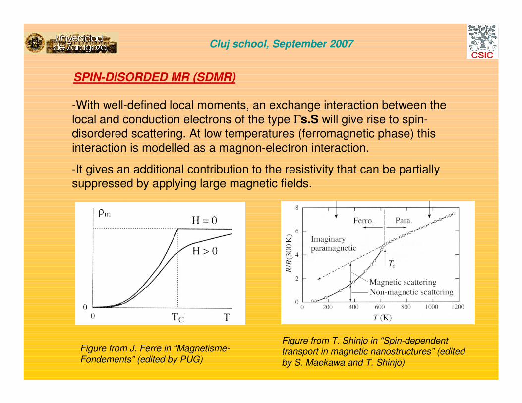
SPIN-DISORDED MR (SDMR)
-With well-defined local moments, an exchange interaction between thelocal and conduction electrons of the type Γs.S will give rise to spin-disordered scattering. At low temperatures (ferromagnetic phase) thisinteraction is modelled as a magnon-electron interaction.
-It gives an additional contribution to the resistivity that can be partiallysuppressed by applying large magnetic fields.
Figure from T. Shinjo in “Spin-dependenttransport in magnetic nanostructures” (editedby S. Maekawa and T. Shinjo)
Figure from J. Ferre in “Magnetisme-Fondements” (edited by PUG)
Cluj school, September 2007

SPIN-DISORDED MR (SDMR) VERSUS COLOSSAL MR (CMR)
Cluj school, September 2007
In both cases, SDMR and CMR, largemagnetic fields are required for large
resistance variations, which isdisadvantageous for applications. Itmostly remains of academic interest
but with little applications
TCLa0.7Sr0.3MnO3
H=0 kOe
H=70 kOe
SDMR ocurrs in metallic systemsand is the largest around Tc
Snyder et al., Phys. Rev. B 53 (1996) 14434
CMR ocurrs in certain systemsshowing spontaneous or field-induced metal-insulator transition
J.M. De Teresa et al., Phys. Rev. B 54 (1996) R12689
Pr2/3Ca1/3MnO3

COLOSSAL MR (CMR) IN MANGANITE OXIDES (A1-xA’xMnO3 type)
Von Helmolt et al., Phys. Rev. Lett. 71 (1993) 2331 (first report of CMR on thin films)
La2/3Ba1/3MnO3-d
Cluj school, September 2007
KEY INGREDIENT: STRONG COMPETITION BETWEEN INSULATING PHASES (CO, AF)AND CONDUCTIVE PHASES (FERROMAGNETIC BY DOUBLE EXCHANGE)
PARAMAGNETIC
FERRO METALLIC
CO I
1 nm (1 µm)
FERRO METALLIC
MAGNETIC FIELD
De Teresa et al., Nature 386 (1997) 256 and many other contributors
CHARGE-ORDERED INSULATOR
FM

THE NANOMETRIC AND MICROMETRIC PHASE SEPARATION
Uehara et al., Nature 399 (1999) 560Asaka et al., Phys. Rev. Lett. 89 (2002) 207203
Nd0.5Sr0.5MnO3
Cluj school, September 2007
(LaPr)5/8Ca3/8MnO3
TEM IMAGES
Dagotto et al., Phys. Rept. 344 (2001) 55 and references therein
⇒ INTRINSIC DISORDER DUE TO THE SOLID SOLUTION WHICH CREATES RANDOM POTENTIALS
⇒EXTRINSIC DISORDER DUE TO SMALL LOCAL COMPOSITIONAL INHOMOGENEITIES AT THE NANOMETRIC LEVEL
THEORETICAL STUDIES SHOW THAT THE SIMILAR ENERGIES OF INSULATING AND METALLIC COMPETING INTERACTIONS PLUS THE
PRESENCE OF DISORDER ALLOW THE PHASE SEPARATION SCENARIO AND THE UNIQUE EFFECT OF THE MAGNETIC FIELD, WHICH FAVORS THE
FERROMAGNETIC METALLIC STATE, AND CONSEQUENTLY THE CMR EFFECT

GIANT
MAGNETORESISTANCE
Cluj school, September 2007

GIANT MR (GMR)
Baibich et al., Phys. Rev. Lett. 61 (1988) 2472
-The GMR effect was first observed in [Fe/Cr]n magnetic multilayers with layerthicknesses comparable to the mean free path.
-Theoretical explanation of the effectcomes from the spin dependence of theconduction in ferromagnetic metals: “spin-up” and “spin-down” conductionelectrons show different bulk andinterface scattering probablility
-Real applications of GMR came afterthe realization of the spin-valve concept(90’s), where the MR ratio is of theorder of 10%
[Ferro/metal]n
Cluj school, September 2007
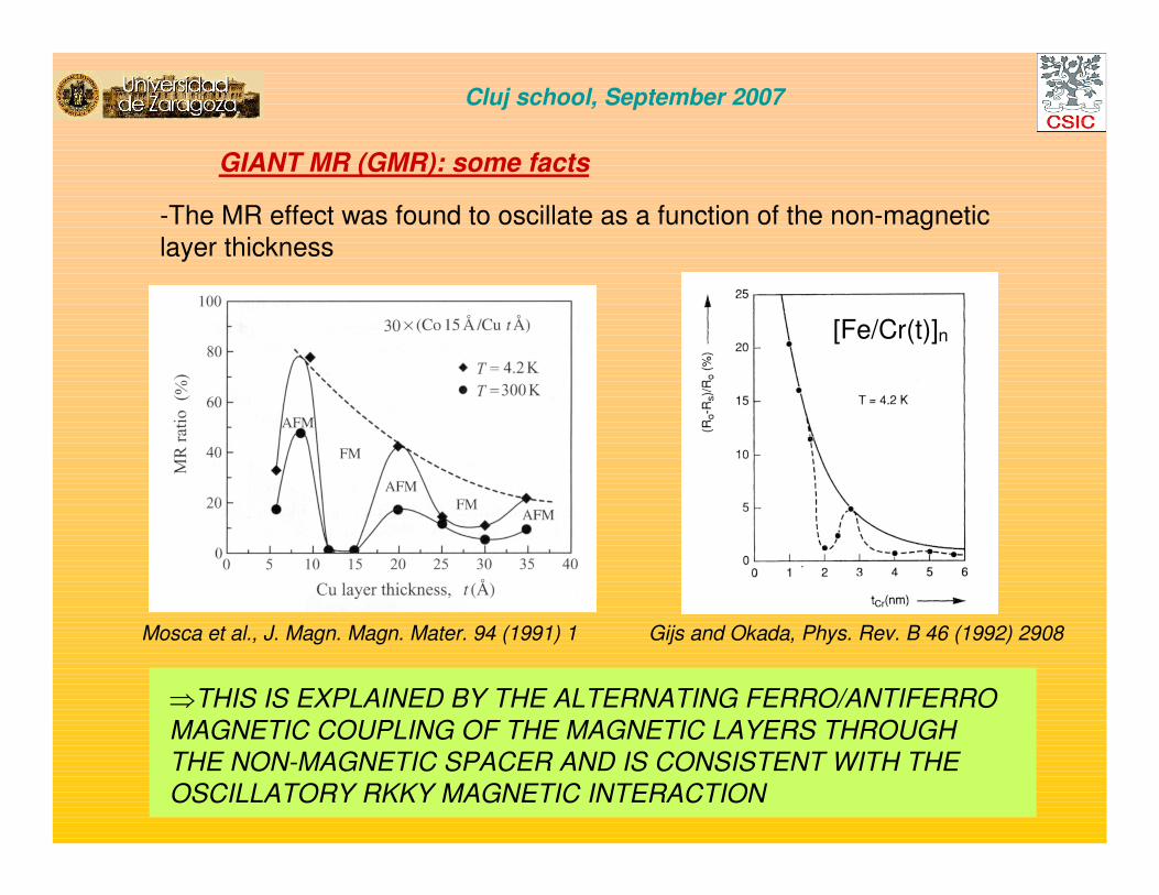
GIANT MR (GMR): some facts
-The MR effect was found to oscillate as a function of the non-magneticlayer thickness
⇒THIS IS EXPLAINED BY THE ALTERNATING FERRO/ANTIFERRO
MAGNETIC COUPLING OF THE MAGNETIC LAYERS THROUGH
THE NON-MAGNETIC SPACER AND IS CONSISTENT WITH THE
OSCILLATORY RKKY MAGNETIC INTERACTION
Mosca et al., J. Magn. Magn. Mater. 94 (1991) 1 Gijs and Okada, Phys. Rev. B 46 (1992) 2908
[Fe/Cr(t)]n
Cluj school, September 2007

GIANT MR (GMR): some facts
-The MR effect is different in amplitude in the “current-in-plane” (CIP) andthe “current-perpendicular to plane” (CPP) geometries
⇒THE ELECTRONS INVOLVED IN THE GMR SCATTERING PROCESSES
AND THE EXACT PROCESSES THEMSELVES ARE DIFFERENT
DEPENDING ON THE GEOMETRY, WHICH LEADS TO DIFFERENT GMR
AMPLITUDES: CPP-GMR IS FOUND TO BE LARGER THAN CIP-GMR
Ono et al., Phys. Rev. B 55 (1997) 14457
As the resistance (R) depends
inversely with the area, in the CPP
geometry R is very small. Normally,
some lithography patterning is
performed to make small areas or
other tricks are applied.
Cluj school, September 2007

GIANT MR (GMR): simple picture
-If we assume that the spin-flip scattering rate of the conduction electrons ismuch lower than the non-flip scattering rate (as normally occurs at T<<TC), theconduction takes place through two independent parallel channels: the “spin-up” and “spin-down” electrons.
Fe Fe FeCr Cr Cr
Fe Fe FeCr Cr Cr ρ↑ = m↑ / (n↑ e2 τ↑)
ρ↓ = m↓ / (n↓ e2 τ↓) e-
e-
e-
e-APPP
PAPGMRρρρρ
ρρρ
4
)( 2
↑↓ −=
−=
↓↑
↓↑
+=
ρρρρ
ρP
4
↓↑ +=
ρρρ AP
↓↑ ≠ ρρ
Cluj school, September 2007

GIANT MR (GMR): theoretical approaches
(for details see the excellent review by Barthélemy et al., Handbook of Magnetic Materials 12, 1999)
- These potential jumps are important provided that the mean free path is larger than thelayers thickness because they produce wavefunction specular reflections and, consequently, wavefunction interferences (“supperlattice” models). In some cases, a “layer-by-layer” approach is enough, only including bulk and interface scattering.
Spin “down” channel in theparallelconfiguration
Spin “up” channelin the parallelconfiguration
Spin “up” or spin“down” channelsin the antiparallelconfiguration
Cluj school, September 2007
*THERE ARE 3 SOURCES OF SCATTERING:
-Bulk scattering events(spikes inside layers)
-Interface scattering events(spikes at interfaces)
-Intrinsic potential changesat the interfaces (jumps)

GIANT MR (GMR): theoretical approaches for CIP-GMR
-Later, the intrinsic potential effects were progressively introduced into themodels in addition to the scattering potentials. Interference between succesivereflections are normally not important in real experiments.
-All previous models assume diffusive transport (total system size larger thanthe mean free path). Some models have also addressed the ballistic regime ofthe GMR (to be realized in systems with very few impurities or nanocontacts)
Example: impurities in Ni
APP
GMRρρρρ
4
)( 2
↑↓ −=
-Initial models were based on free electrons scatteredby spin-dependent scatterers. Controlled doping with impurities allows tailoring the GMR effect.
ρρρρ↓↓↓↓
ρρρρ↑↑↑↑
Cluj school, September 2007

GIANT MR (GMR): theoretical approaches for CPP-GMR
-CPP transport generates spin
accumulation around the interfaces that must be balanced by spinrelaxation (Valet and Fert theory). When spin relaxation is taken intoaccount, the spin diffusion length
(much larger than the mean free path) becomes the most relevant scalinglength.
[Co/Ag(d)]N ; L=0.72 µµµµm
-The intrinsic contribution to the CPP-GMR can be normally expressedthrough the concept of “interface
resistance”, which has contributionsfrom the potential steps at theinterface plus interface diffusescattering by defects/dopants.
Cluj school, September 2007

GIANT MR (GMR) IN GRANULAR MATERIALS
-The GMR effect can be realized in granular materials / thin films with immiscible magnetic/non-magnetic metals due to the same physicalphenomena. The type of response is less suitablefor applications, especially if hysteresis is present.
Berkowitz et al., Phys. Rev. Lett. 68 (1992) 3745; Xiao et al., Phys. Rev. Lett. 68 (1992) 3749; Wang and Xiao, Phys. Rev. B 50 (1994) 3423; Batlle andLabarta, J. Phys. D: Appl. Phys. 35 (2002) R15
H
H=0
CoCu
Cluj school, September 2007

TUNNEL
MAGNETORESISTANCE
Cluj school, September 2007

TUNNEL MAGNETORESISTANCE (TMR): how it all started
1975
1982
1995
Moodera et al., Phys. Rev. Lett. 74 (1995) 3273
Maekawa and Gaefvert, IEEE Transactionson Magnetics 18 (1982) 707
Julliere, Phys. Lett. 54A (1975) 225
Fe/Ge/Co
CoFe/Al2O3/Co
insulator
Cluj school, September 2007

TMR: first approach to the tunnel conductance
t
zizU
z
z
m ∂∂
=+∂
∂−
)()(
)(
2 2
22 ψψ
ψh
h
dk
k ekk
kkT '2
222
222
)'(
'16 −=
2
)(2'
h
zEUmk
−=
TUNNEL CURRENT:
)(2
**
zzm
iJ k ∂
∂−
∂∂
=ψ
ψψ
ψh
dk
kk eTJ'22 −αα
INCIDENT WAVE TRANSMITTED WAVE
eikz Teikz
ENERGY
BARRIER
U
POSITION
z
ψψψψ(z)
d
EXPONENTIAL DEPENDENCE OF
THE CURRENT WITH THE BARRIER
WIDTH AND THE SQUARED ROOT
OF THE BARRIER HEIGHT
Cluj school, September 2007

TMR: the basics of magnetic tunnel junctions
RP
RAP
TMR (%)= 100 x (RAP-RP)/RAP
TOP
ELECTRODE
BARRIER
BOTTOM
ELECTRODE
F1 / I / F2
V EF
⇒⇒⇒⇒ MAGNETIC TUNNEL JUNCTIONS ARE FORMED BY TWO MAGNETIC MATERIALS (ELECTRODES) SEPARATED BY A
NANOMETRIC INSULATING LAYER (BARRIER). CONDUCTION
TAKES PLACE THROUGH TUNNELLING.
TMR=100 x 2P1P2/(1+ P1P2) (Julliere’s model)
Cluj school, September 2007

Let N(EF)= (1/2) * Total number of electrons at EFWe define an effective spin polarization: P=[N↑↑↑↑(EF)-N↓↓↓↓(EF)]/[N↑↑↑↑(EF)+N↓↓↓↓(EF)]
PARALLEL MAGNETIC CONFIGURATIONMAJORITY MINORITY
EFEF
MAJORITY MINORITY
ANTIPARALLEL MAGNETIC CONFIGURATION
IP αααα (1+P1)(1+P2) + (1-P1)(1-P2)= 2(1+P1P2)
[ ])()()()()(),( 21
2EfeVEfENeVENETEVI −−−α
)()()( 21
2
FFF ENENETV
Iα )()( 21 FF ENEN
V
Iα
IF THE SPIN IS CONSERVED:
F1 / I / F2
V EFAPROX.
TMR: the idea behind Julliere’s model
IAP αααα (1+P1)(1-P2) + (1-P1)(1+P2)= 2(1-P1P2)
⇒⇒⇒⇒ TMR=(RAP-RP)/RAP=1-(IAP/IP)=2P1P2/(1+ P1P2)
Cluj school, September 2007

TMR: the use of half metals can give rise to huge TMR ratios
MANGANITE-based MTJs
Bowen et al., Appl. Phys. Lett. 82, 233 (2003)
MR>1500% at 5K, which corresponds to P=0.95 (however,the MR vanishes at 300 K)
Cluj school, September 2007
HEUSLER ALLOYS-based MTJs
La0.7Sr0.3MnO3
La0.7Sr0.3MnO3
SrTiO3
TEM picture by J.L. Maurice
Tezuka et al., Appl. Phys. Lett. 89, 252508 (2006)
MR=175% at room temperature, which corresponds to P=0.68

TMR: understanding the TMR effect
( )21
21
1200(%)
PP
PPxTMR
+=
F1
I F2
?)()(
)()(
↓↑
↓↑
+
−=
FF
FF
ENEN
ENENP
-PHOTOEMISSION: INFORMATION ON
↓↑
↓↑
+
−=
)()(
)()(
FF
FF
ENEN
ENENP
P(Co)<0
-TUNNEL JUNCTIONS F/I/S: INFORMATION ON P(Co) IN TUNNELLING
P(Co)>0 WITH Al2O3 BARRIER
What P value is the right one to be
included in Julliere’s formula?
FERMI ENERGY
MAJORITARY
e-“SPIN UP”
MINORITARY
e-“SPIN DOWN”
JULLIERE’S MODEL)
*“s-type” BANDS ⇒ lower density ofstates, positively polarized, more delocalized electrons
*“d-type” BANDS ⇒ higher density ofstates, negatively polarized, more localized electrons
[experiments carried out by Tedrow and
Meservey: see review in Phys. Repts. 238
(1994) 173]
THE EXAMPLE OF COBALT
Cluj school, September 2007

TEM IMAGE BY J.L. MAURICE
Co
* P (La0.7Sr0.3MnO3) ≈≈≈≈ +100%
* P (Co) = ?
( )21
21
1200(%)
)(*100
PP
PPxTMR
R
RR
P
PAP
+==
−
La0.7Sr0.3MnO3
SrTiO3
If P(Co) > 0 ⇒⇒⇒⇒ TMR(%) >0
If P(Co) < 0 ⇒⇒⇒⇒ TMR(%) <0
TMR: understanding the TMR effect
DESIGNED EXPERIMENT: La0.7Sr0.3MnO3/ I /Co (I=SrTiO3, Al2O3, CeO2)
(experiments performed in Orsay with A. Fert’s Group)
The experiment aims at probing the spin polarization of Co when usingdifferent barriers in tunnel junctions, which can be related to thepreferential tunnelling of “s-type” or “d-type” electrons from Co.
Cluj school, September 2007

La0.7Sr0.3MnO3 / SrTiO3 / Co
INVERSE TMR
RAP<RP
P(Co) IS NEGATIVE
NORMAL TMR
RP<RAP
P(Co) IS POSITIVE
TMR ∝∝∝∝ P(LSMO)P(Co) /[1+P(LSMO)P(Co) ]; with P(LSMO) > 0J.M. De Teresa et al., Phys. Rev. Lett. 82 (1999) 4288; J.M. De Teresa et al., Science 286 (1999) 507; Hayakawa et al., J. Appl. Phys. 91 (2002) 8792; Hayakawa et al., Jpn J. Appl. Phys. 41 (2002) 1340
La0.7Sr0.3MnO3 / SrTiO3 / Al2O3 / Co
3.6 105
3.8 105
4 105
4.2 105
4.4 105
4.6 105
4.8 105
-0.04 -0.02 0 0.02 0.04
-5
0
5
10
15
CAMPO MAGNETICO, H (T)
(d)
MAGNETIC FIELD (T)
RE
SIS
TA
NC
E (
OH
MS
)
MA
GN
ET
OR
ES
IST
AN
CE
(%)
3000
3200
3400
3600
-0.2 -0.15 -0.1 -0.05 0 0.05 0.1 0.15 0.2
-15
-10
-5
0
5
CAMPO MAGNETICO, H (T)
La0.7
Sr0.3
MnO3/SrTiO
3/Co
(a)
MAGNETIC FIELD (T)
RE
SIS
TA
NC
E (
OH
MS
)
MA
GN
ET
OR
ES
IST
AN
CE
(%)
TMR: understanding the TMR effect
La0.7Sr0.3MnO3/Al2O3/CoLa0.7Sr0.3MnO3/SrTiO3/Co
Cluj school, September 2007

DEPENDENCE OF THE TUNNEL
MAGNETORESISTANCE WITH VOLTAGE
I= SrTiO3: CURRENT BY “d-type” ELECTRONS
I= Al2O3: CURRENT BY “s-type” ELECTRONS
V+ La0.7Sr0.3MnO3
V- Co
-5
0
5
10
15
20
-0.6 -0.4 -0.2 0 0.2 0.4 0.6
VOLTAJE APLICADO (VOLTIOS)
T= 40 K
APPLIED VOLTAGE (V)
MA
GN
ET
OR
ES
IST
AN
CE
(%
)
FERMI LEVEL
3 eV
2 eV
1 eV
-3 eV
-2 eV
-1 eV
SPIN ↑↑↑↑Co "d" electrons
SPIN ↓↓↓↓
V -
V +
TMR: understanding the TMR effect
-30
-20
-10
0
-0.6 -0.4 -0.2 0 0.2 0.4 0.6
VOLTAJE APLICADO (VOLTIOS)
T=40 K
MA
GN
ET
OR
ES
IST
AN
CE
(%
)
APPLIED VOLTAGE (V)
Cluj school, September 2007

sp-d BONDING
CoAlO CoTiO
d-d BONDING
Al2O3/Co INTERFACE SrTiO3/Co INTERFACE
Selection of “s” electrons Selection of “d” electrons
TMR: understanding the TMR effect
THE INTERFACE CONTROLS THE STARTING POINT OF THE EVANESCENT WAVE IN THE BARRIER
(related theoretical articles supporting these experiments: Tsymbal et al., J. Phys. Condens. Matter. 9 (1997) L411; Stoeffler, J. Phys. Condens. Matter. 16 (2004) 1603; Oleinik et al., Phys. Rev. B 65 (2002) 020401; Velev et al., Phys. Rev. Lett. 95 (2005) 216601)
Cluj school, September 2007

TMR: understanding the TMR effect
-BAND STRUCTURE OF THE
INSULATOR +TRANSMISSION OF
THE TUNNELLING ELECTRONS
EXPERIMENTAL AND THEORETICAL STUDIES PERFORMED IN THE LAST YEARS
INDICATE THAT RELIABLE CALCULATIONS OF THE TMR IN TUNNEL JUNCTIONS
MUST TAKE INTO ACCOUNT:
Cluj school, September 2007
-BAND STRUCTURE OF THE
FERROMAGNET+INTERFACIAL
RESONANT STATES (THEY
CAN DEPEND ON BONDING)
-BAND STRUCTURE OF THE
FERROMAGNET+INTERFACIAL
RESONANT STATES (THEY
CAN DEPEND ON BONDING)

TMR: MR limitation (~70%) in Al2O3-based magnetic tunnel junctions
Tsunoda et al., Appl. Phys. Lett. 17 (2002) 3135
Wang et al., IEEE Trans. Magn. 40 (2004) 2269
Optimization of the Al plasma-oxidation
Use of CoFeB electrodes
Cluj school, September 2007

5 nmCoFe
CoFe
MgO
S.S.P. Parkin et al., Nature materials 3 (2004) 862
TMR: MgO-based sputtered magnetic tunnel junctions
Cluj school, September 2007
CoFe/MgO/CoFe, TMR= 150% at RT
CoFeB/MgO/CoFeB, TMR= 355% at RT
Djayaprawira et al., Appl. Phys. Lett. 86 (2005) 092502
Ikeda et al., J. Appl. Phys. 99 (2006) 08A907

TMR: MgO-based MBE-grown single-crystal magnetic tunnel junctions
[Yuasa et al., Appl. Phys. Lett. 89 (2006) 042505]
Cluj school, September 2007
Yuasa et al., Nature materials 3 (2004) 868
Fe/MgO/Fe, TMR= 200% at RT Co/MgO/Co, TMR= 410% at RT

Theoretical explanations to the TMR properties of MgO-based MTJs
Cluj school, September 2007
Review article: Tiusan et al., J. Phys.: Condens. Matter 19
(2007) 165201
*General considerations: mutilchannel conductance with conservation of spin and symmetry
Fe, SPIN UP Fe, SPIN DOWN

*Fe, Large MgO barrier thickness (only k||=0 electrons tunnel efficiently)
*Fe, Small MgO barrier thickness (k||≠≠≠≠0 electrons and interfacial states important)
Theoretical explanations to the TMR properties of MgO-based MTJs
Cluj school, September 2007
The most efficient conduction channel is
through electrons arisingfrom the band with ∆1
symmetry, which is not available in the antiparallel
magnetic configuration, giving rise to a high
resistance state.
Electrons arising from bands with ∆2 and ∆5 symmetry also contribute to the conductance as well as the Fe(100) surface state in the AP state,
with ∆1 symmetry. All this reduces the TMR at low MgO thickness.
*bcc Co: only the band with ∆1 symmetry is present at the EF in the spin-up subband, which implies negligible conductance in the AP configuration

Summary of TMR record values in magnetic tunnel junctions
Cluj school, September 2007
[Zhu and Park, Materials Today 9 (2006) 36]

Tsunekawa et al., Appl. Phys. Lett. 87, 072503 (2005)
Characteristics of magnetic tunnel junctions for real applications
Cluj school, September 2007
In order to get a high operating frequency and low noise, the resistance-area product should be lower than 4 ΩµΩµΩµΩµm2
Insertion of a thin Mg layer (4Å)

TUNNEL MR (TMR) IN GRANULAR MATERIALS
-The TMR effect can be realized in granular materials / thin films with immisciblemagnetic metals / insulators due to the samephysical phenomena.
Gittleman et al., Phys. Rev. 5 (1972) 3609; Helmanand Abeles, Phys. Rev. Lett. 37 (1976) 1429;Inoueand Maekawa, Phys. Rev. B 53 (1996) R11927; Mitani et al., J. Magn. Mater. 165 (1997) 141; Batlle and Labarta, J. Phys. D: Appl. Phys. 35 (2002) R15
H
H=0
Fe,Co, Ni...
SiO2, Al2O3 ,...
~20 nm
Co in Zr2O3 matrix
Cluj school, September 2007

OTHER
MAGNETORESISTIVE
EFFECTS
Cluj school, September 2007

MAGNETOTRANSPORT IN NANOCONSTRICTIONS (I)
-Transport is said to take place in a “nanoconstriction” or “point contact” if the electronmean free path, mfp ~ constriction size, d
-If the inelastic mfp > constriction size ⇒⇒⇒⇒ we have “diffusive” conduction
-If the elastic and inelastic mfp > constriction size ⇒⇒⇒⇒ we have “ballistic” conduction
-If the Fermi length of the electrons ~ constriction size ⇒⇒⇒⇒ we have “quantum” conduction
Ono et al., Appl. Phys. Lett. 75, 1622 (1999)
*See the following reviews: Halbritter et al., Adv. Phys. 53 (2004) 939; Agraït et al., Phys. Rep. 377 (2003) 81
2e2/h=1/(12.9 Kohm) Wees et al., Phys. Rev. Lett. 60 (1988) 848
Ni Nid
Cluj school, September 2007
Quantum of conductance

MAGNETOTRANSPORT IN NANOCONSTRICTIONS (II)
*IS BALLISTIC MAGNETORESISTANCE (BMR) HUGE?... UNDER DISCUSSION
nanocontacts
Ni-Ni
H
H=0
Domain wall
N.GARCÍA: SEE TATARA
ET AL., PHYS. REV. LETT.
83 (1999) 2030
supporters
H. CHOPRA: SEE
SULLIVAN ET AL., PHYS.
REV. B 71 (2005) 024412
detractors
EGELHOFF: SEE EGELHOFF ET
AL., J. APP. PHYS. 95 (2004) 7554
I. SCHULLER: SEE MONTERO
ET AL., PHYS. REV. B 70 (2004)
184418
R. BUHRMAN: SEE OZATAY ET
AL., J. APP. PHYS. 95 (2004) 7315
Cluj school, September 2007
M. VIRET: SEE GABUREAC ET
AL., PHYS. REV. B 69 (2004) 100401

MAGNETOTRANSPORT WITH CARBON NANOTUBES (I)
Tsukagoshi et al., Nature 401, 572 (1999)
⇒ One of the first results showing that it is possibleto keep the spin information along relatively long
distances through carbon nanotubes
Cluj school, September 2007

MAGNETOTRANSPORT WITH CARBON NANOTUBES (II)
γ= spin polarizazion of the electronstransmitted at the interface
τn=dwell time of the electrons in thecarbon nanotube
τsf= spin lifetime in the carbonnanotube
Hueso et al., Nature 445, 410 (2007)
Cluj school, September 2007

SPIN TRANSFER (current-driven magnetization reversal)
Co
Cu
e-
Co
*THE MAGNETIZATION STATE AFFECTS THE CURRENT (GMR, TMR,...). CORRESPONDINGLY, THE CURRRENT CAN AFFECT THE MAGNETIZATION STATE
IN HETEROSTRUCTURES WITH GMR IN HETEROSTRUCTURES WITH TMR
Deac et al., Phys. Rev. B 73 (2006) 064414 Meng et al., Appl. Phys. Lett. 88 (2006) 082504
I ~ 106-108 A/cm2
Cluj school, September 2007

APPLICATIONS OF
MAGNETORESISTIVE
DEVICES
Cluj school, September 2007
MORE INFORMATION
IN THE LESSON ON
“MAGNETIC SENSORS
AND ACTUATORS”
(THIS AFTERNOON)

OVERVIEW OF THE APPLICATION OF MR DEVICES FOR SENSING
MANUFACTURING INDUSTRY:Example: measuring the rotation velocity
AUTOMOTIVE INDUSTRY: Example: tracking the pedals positions
AERONAUTICS: Example: measuring the earth’s magnetic field
Cluj school, September 2007
BIOSENSORS:Example: DNA biochips
MAGNETIC STORAGE INDUSTRY:Example: read heads
HUMAN ELECTROMAGNETIC ACTIVITY:Example: brain/heartelectromagnetic fields

B. Dieny et al., J. Appl. Phys. 69 (1991) 4774
⇒THIS CONCEPT IS VERY USEFUL FOR
APPLICATIONS DUE TO THE LOW FIELD
REQUIRED TO GET A SIGNIFICANT MR
RESPONSE BUT THE AMPLITUDE OF THE
EFFECT IS SIGNIFICANTLY REDUCEDThe spin-valve concept has alsobeen applied to TMR-based devices
H
Cluj school, September 2007
EXCHANGE BIAS
GMR AND TMR: THE SPIN-VALVE CONFIGURATION

H
⇒THE LINEAR RESPONSE AS A
FUNCTION OF THE APPLIED MAGNETIC
FIELD IS VERY USEFUL TO SENSE LOW
MAGNETIC FIELDS OF APPLICATION IN
CERTAIN MAGNETIC SENSORS
The crossed-geometryconcept has also beenapplied to TMR-based devices
Cluj school, September 2007
GMR AND TMR: CROSSED GEOMETRY OF THE EASY DIRECTIONS OF ELECTRODES FOR LINEAR RESPONSE AT LOW FIELDS

*EXCHANGE BIAS
Cluj school, September 2007

Cluj school, September 2007
THE DISCOVERY OF EXCHANGE BIAS
Co/CoO nanoparticles
W.H. Meiklejohn and C.P. Bean, Phys. Rev. 102 (1956) 1413
T=77 K, AFTER COOLING
UNDER FIELD
EXTRA INTERNAL
BIASING FIELD

Cluj school, September 2007
A FEW BASIC CONCEPTS IN EXCHANGE BIAS
REVIEW ARTICLES ON EXCHANGE BIAS: J. Nogues et al., J. Magn. Magn. Mater. 192 (1999) 203; J. Nogues et al., Phys. Reports. 422 (2005) 65
1)SHIFT IN THE HYSTERESIS LOOP (HE)
2)INCREASE IN THE COERCIVITY (∆HC)
3)UNIAXIAL ANISOTROPY (ΚU)

EXCHANGE BIAS IN THIN FILMS
Cluj school, September 2007
REVIEW ARTICLES ON EXCHANGE BIAS: J. Nogues et al., J. Magn. Magn. Mater. 192 (1999) 203; J. Nogues et al., Phys. Reports. 422 (2005) 65
NiFe/FeMn thin films
EXCHANGE BIAS IS AN INTERFACIAL EFFECT. IT STRONGLY DEPENDS ON THE
SPIN CONFIGURATION AT THE INTERFACE

MATERIALS FOR EXCHANGE BIAS
IN THIN FILMS
J. Nogues et al.
FeMn
NiMn
IrMn
TB TN TCmeasurement
TCooling under field
TB

J. Nogues et al., Phys. Reports. 422 (2005) 65
Cluj school, September 2007
EXCHANGE BIAS WITH MAGNETIC NANOPARTICLES
Fe nanoparticles
Cr2O3 matrix (AFM)

*MAGNETIC RANDOM
ACCESS MEMORIES
Cluj school, September 2007
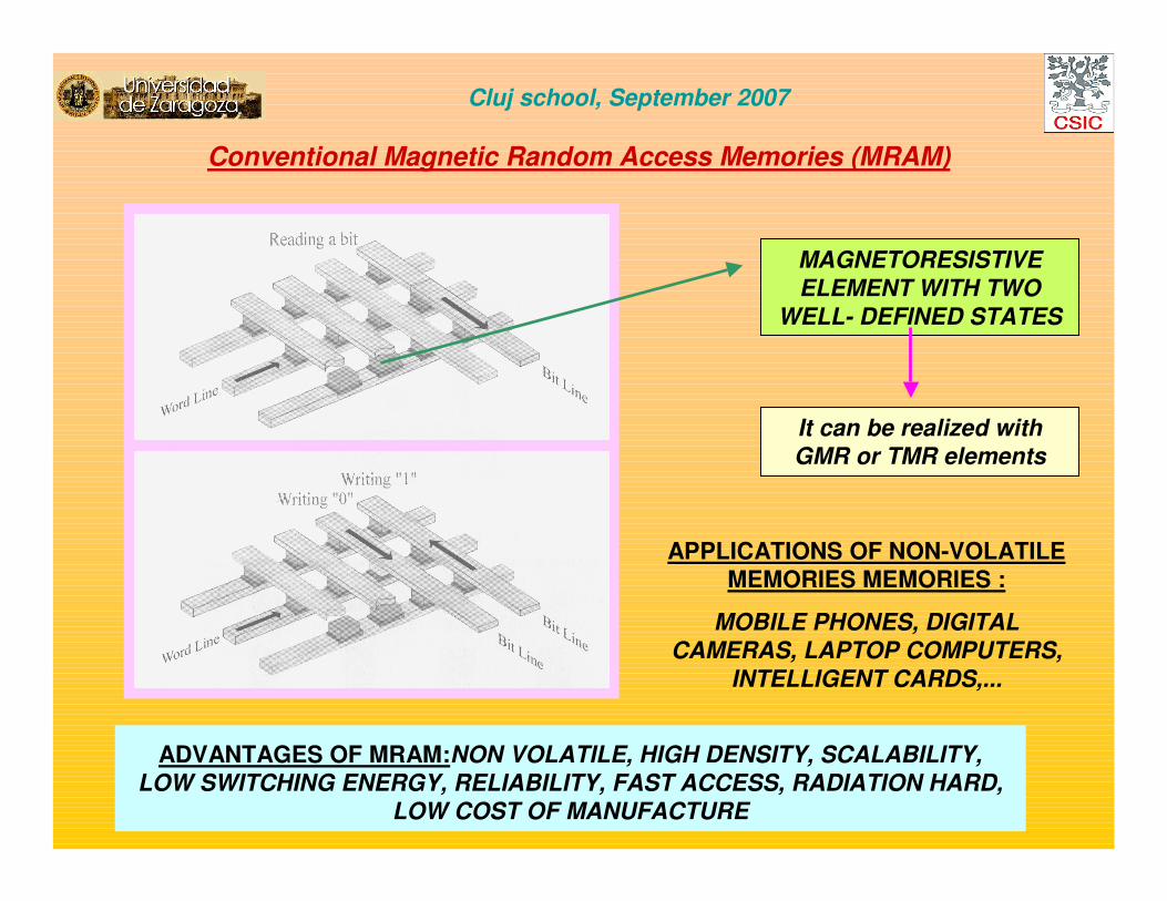
Conventional Magnetic Random Access Memories (MRAM)
Cluj school, September 2007
ADVANTAGES OF MRAM:NON VOLATILE, HIGH DENSITY, SCALABILITY, LOW SWITCHING ENERGY, RELIABILITY, FAST ACCESS, RADIATION HARD,
LOW COST OF MANUFACTURE
APPLICATIONS OF NON-VOLATILE
MEMORIES MEMORIES :
MOBILE PHONES, DIGITAL CAMERAS, LAPTOP COMPUTERS,
INTELLIGENT CARDS,...
MAGNETORESISTIVE ELEMENT WITH TWO
WELL- DEFINED STATES
It can be realized with GMR or TMR elements

S. Parkin in “Spin dependent transport in Magnetic Nanostructures”, edited by Maekawa and Shinjo, Taylor and Francis; R. Sousa et al., C.R. Physique 6 (2005)1013; Zhu et al., Materials Today 9, 36 (2006)
Cluj school, September 2007
Conventional Magnetic Random Access Memories (MRAM)
A diode or a transitor is required in order to read one single bit. Thus, the memory cannot be dense.
Distribution of resistance values
is crucial
Writing is normally performed with coherent magnetization rotation
with a field parallel to the easy axis plus another
one perpendicular

Other strategies in Magnetic Random Access Memories (MRAM)
Cluj school, September 2007
SPIN-RAM MEMORY WITH SPIN TORQUE FOR MAGNETIC SWITCHING OF THE STORAGE LAYER
R. Sousa et al., C.R. Physique 6 (2005)1013; Zhu et al., Materials Today 9, 36 (2006)

*The “universal” memory should have the speed of “SRAM”, the density of“DRAM” and non volatility as “FLASH”. Will the MRAM attain all these features?
UPDATES TO THE MRAM GAME CAN BE FOUND AT
http://www.mram-info.com
Comparison of magnetic memories
Cluj school, September 2007

Honeywell develops non-volatile MRAM for strategic space applications. Honeywell has
developed a 1 Mbit non volatile static memory component for strategic space electronics applications(see related story). Built with Honeywell's radiation-hardened, silicon-on-insulator (SOI)
complementary metal oxide semiconductor (CMOS) technology, and combined with magnetic thinfilms, the new memory component provides high reliability for low-voltage systems operating in
radiation environments. The magnetic RAM runs from a 3.3-volt power supply and has high reliability, enabling it to operate through the natural radiation found in space. It offers nearly unlimited read/writecycles (>1e15) and uses Honeywell's 150-nanometer SOI CMOS technology as well as a unique set of
wafer processes developed at the company's "Trusted Foundry" in Plymouth, Minn.
NEWS IN APRIL 2007:
NEWS IN JUNE 2007:
Freescale Semiconductor has expanded its award-winning MRAM family with the world’s
first 3-volt 4Mbit extended temperature range (-40 to +105°C) non-volatile RAM (nvRAM) product.This device enables entry into more rugged application environments, such as industrial, military and aerospace and automotive designs.
NEWS IN AUGUST 2007:
IBM has linked with Japan's TDK to develop so-called spin torque transfer RAM (random
access memory) or STT-RAM. In STT-RAM, an electric current is applied to a magnet to change the direction of the magnetic field. The direction of the magnetic field (up-and-down or left-to-right) causes a change in resistance, and the different levels of resistance register as 1s or 0s.

Cluj school, September 2007
CONCLUSIONS ANS PERSPECTIVES
MAGNETORESISTIVE DEVICES CONSTITUTE
A MAGNIFICENT PLAYGROUND TO STUDY EXCITING
MAGNETIC PHENOMENA
MAGNETORESISTIVE DEVICES ARE WIDELY
USED IN TODAY’S TECHNOLOGY AND ARE
EXPECTED TO BRING ABOUT NEW PRODUCTS
IN NEXT FUTURE

THANKS FOR YOUR
ATTENTION
LATEST NEWS:
SIESTA IS FORBIDDEN TODAY!