maharashtra state board of technical education (autonomous...
TRANSCRIPT
MAHARASHTRA STATE BOARD OF TECHNICAL EDUCATION (Autonomous) (ISO/IEC - 27001 - 2005 Certified) SUMMER– 14 EXAMINATION Subject Code: 12159 Model Answer
Page 1 of 24
Important Instructions to examiners: 1) The answers should be examined by key words and not as word-to-word as given in the model answer scheme. 2) The model answer and the answer written by candidate may vary but the examiner may try to assess the understanding level of the candidate. 3) The language errors such as grammatical, spelling errors should not be given more Importance (Not applicable for subject English and Communication Skills. 4) While assessing figures, examiner may give credit for principal components indicated in the figure. The figures drawn by candidate and model answer may vary. The examiner may give credit for any equivalent figure drawn. 5) Credits may be given step wise for numerical problems. In some cases, the assumed constant values may vary and there may be some difference in the candidate’s answers and model answer. 6) In case of some questions credit may be given by judgement on part of examiner of relevant answer based on candidate’s understanding. 7) For programming language papers, credit may be given to any other program based on equivalent concept.
Q. 1 a) Attempt any THREE of the following
i ) Give the classification of Automobile ( one mark for each category any four categories)
Automobile means a self propelling vehicle that moves on surface, road, highways etc. It is also known as a motor vehicle. Automobiles are classified based on following criteria: -
1. Based on number of wheels a. Two wheeler b. Three wheeler c. Four wheeler d. Six wheeler e. Eight wheeler
2. Based on source of power for propulsion a. Engine powered – Diesel, petrol, CNG, LPG engine b. Electric motor powered c. Hybrid- Electric, pneumatic, hydrostatic
3. Based use a. Non transport vehicles b. Transport vehicles
4. Based on where they normally ply

MAHARASHTRA STATE BOARD OF TECHNICAL EDUCATION (Autonomous) (ISO/IEC - 27001 - 2005 Certified) SUMMER– 14 EXAMINATION Subject Code: 12159 Model Answer
Page 2 of 24
a. On highway vehicle b. Off highway vehicles- Mining, construction, agriculture, military etc
5. Based on layout a. Front engine front wheel drive vehicles b. Front engine rear wheel drive vehicles c. Rear engine rear wheel drive vehicles d. Front/ rear engine all wheel drive vehicles
ii) List the major vehicle manufacturers in India (For correct name of any eight of the following should be given full (4) marks)
1. Tata Motors Ltd (TML) 2. Ashok Leyland Ltd (ALL) 3. Maruti Udyog Ltd (MUL) 4. Bajaj Auto Ltd (BTL) 5. Force Motors 6. Eicher Motor 7. TVS Motor Company Ltd 8. Hero Motocorp 9. Honda scooters and motorcycles 10. Yamaha India 11. Ford 12. Hyundai Motors Ltd
iii) What are the types of vehicle layouts? Explain. (2.5 marks for concepts and stating all five and 1.5 marks for explaining any one among them)
The way major systems viz. Engine, driving wheels, steering wheels, transmission, drive trains are laid in a given vehicle defines it’s layout. We find following layouts in different vehicles
1. Front Engine Front Wheel Drive (FEFWD) Layout 2. Front Engine Rear Wheel Drive (FEFWD) Layout 3. Rear Engine Rear Wheel Drive (FEFWD) Layout 4. Front Engine All Wheel Drive (FEAWD) Layout 5. Rear Engine all Wheel Drive (REAWD) Layout
Front Engine front wheel drive layout is used in today’s hatch back cars. In this layout all subsystems of a vehicle are laid along its length in such a way that there is a engine at front side while front wheels are driving wheels.
MAHARASHTRA STATE BOARD OF TECHNICAL EDUCATION (Autonomous) (ISO/IEC - 27001 - 2005 Certified) SUMMER– 14 EXAMINATION Subject Code: 12159 Model Answer
Page 3 of 24
iv) Define battery rating and battery capacity.( four marks for appropriate answer)
In order to compare and select batteries for a given application they are graded based on how much current they provide and for how much time (either in minutes or hours). As per various standards viz. SAE, DIN, JIS etc batteries are rated based on following
1. Battery Rating –battery rating of a particular battery are determined by how much current it can produce and how long it can sustain this current. For example when battery rating is 44 Ah then we expect 2.2 A current for 20 hours
2. Battery Capacity- It is expressed in terms of ampere hour ( Ah), minutes or cold cranking ampere
b) Attempt any ONE of the following i) Write with a neat sketch working of starting motor
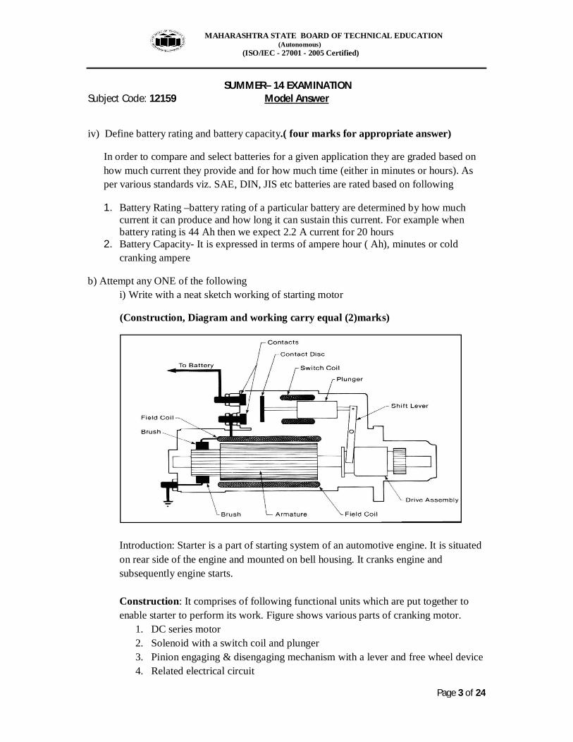
(Construction, Diagram and working carry equal (2)marks)
Introduction: Starter is a part of starting system of an automotive engine. It is situated on rear side of the engine and mounted on bell housing. It cranks engine and subsequently engine starts. Construction: It comprises of following functional units which are put together to enable starter to perform its work. Figure shows various parts of cranking motor.
1. DC series motor 2. Solenoid with a switch coil and plunger 3. Pinion engaging & disengaging mechanism with a lever and free wheel device 4. Related electrical circuit
MAHARASHTRA STATE BOARD OF TECHNICAL EDUCATION (Autonomous) (ISO/IEC - 27001 - 2005 Certified) SUMMER– 14 EXAMINATION Subject Code: 12159 Model Answer
Page 4 of 24
Working: Starter working can be expressed using following points
1. Ignition switch, as we turn a ignition key, completes circuit through switch coil.
2. This energises solenoid to enable plunger to shift in left hand direction. 3. Pinion engages with flywheel ring gear due to pulling of shift lever on one
side and contact discs by coming in contact with contacts allow battery current to pass through field coil, brush to earth to earth terminal
4. Motor starts rotating and makes pinion, which is mounted on armature shafts, to rotate a engine flywheel
5. Due to cranking the engine starts and starter motor disengages from flywheel ring due to presence of free wheel clutch.
6. Due to leaving ignition key to return to its original position, the solenoid de- energises making the contact disks to return to its original position. Hence motor stops and pinion also returns to its original position.
ii) Show with a neat sketch working of rack and pinion type of Steering Gearbox used in automobile and explain it.
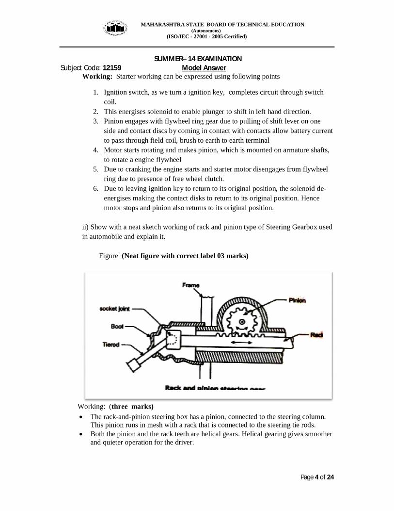
Figure (Neat figure with correct label 03 marks)
Working: (three marks) The rack-and-pinion steering box has a pinion, connected to the steering column.
This pinion runs in mesh with a rack that is connected to the steering tie rods. Both the pinion and the rack teeth are helical gears. Helical gearing gives smoother
and quieter operation for the driver.
MAHARASHTRA STATE BOARD OF TECHNICAL EDUCATION (Autonomous) (ISO/IEC - 27001 - 2005 Certified) SUMMER– 14 EXAMINATION Subject Code: 12159 Model Answer
Page 5 of 24
Turning the steering wheel rotates the pinion, and moves the rack from side to side. Ball joints at the end of the rack locate the tie-rods and allow movement in the steering and suspension.
Mechanical advantage is gained by the reduction ratio. The value of this ratio depends on the size of the pinion.
A small pinion gives light steering, but it requires many turns of the steering wheel to travel from lock, to lock. A large pinion means the number of turns of the steering column is reduced, but the steering is heavier to turn.
Provide low gear reduction for car. Occupies less space and less number of linkages.
Uses: All most all small cars like maruti 800, Alto, Wagon R, Sweft Dezire, i10 etc houses this type of steering gearbox.
Q. 2 Attempt any Four of the following
a) Describe working of a single plate clutch with a diagram( 02 marks for diagram, 02 marks for working)
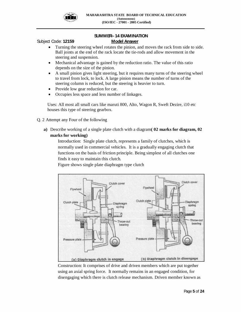
Introduction: Single plate clutch, represents a family of clutches, which is normally used in commercial vehicles. It is a gradually engaging clutch that functions on the basis of friction principle. Being simplest of all clutches one finds it easy to maintain this clutch. Figure shows single plate diaphragm type clutch
Construction: It comprises of drive and driven members which are put together using an axial spring force. It normally remains in an engaged condition, for disengaging which there is clutch release mechanism. Driven member known as
MAHARASHTRA STATE BOARD OF TECHNICAL EDUCATION (Autonomous) (ISO/IEC - 27001 - 2005 Certified) SUMMER– 14 EXAMINATION Subject Code: 12159 Model Answer
Page 6 of 24
clutch plate is sandwiched between flywheel on engine side and pressure plate on gear box side. It consists of splined hub, web and rim and a clutch lining material is riveted on both the sides of rim. A Pressure plate, thrust springs and clutch release levels known as fingers are assembled together in a clutch cover and the whole assembly is bolted to flywheel by inserting clutch plate in between. Clutch plate is splined on a clutch shaft which enters into gearbox on the other end.
Working: Clutch remains usually in engaged condition. It is required to depressed clutch pedal to disengage the clutch. When a driver or an operator drives a vehicle he is required to engage clutch by depressing clutch pedal. As he/ she depresses the clutch pedal effort applied gets transmitted either through level or cable to clutch release fork. The fork pushes clutch release bearing towards engine side due to which clutch release levels shown in figure get displaced getting pressure plate in backward direction. This action creates clearance between drive and driven members resulting disengagement of clutch.
As the driver leaves clutch pedal it returns to its original position due to which pressure plate put thrust on clutch plate from one side and flywheel on the another. This is how clutch gets engaged
b) State the necessity of gear box in automobile.
( four marks for appropriate answer) A vehicle performs means it (explain each point in two to three lines)
1. advances and reverses 2. cruises 3. accelerates and decelerates 4. negotiates slope, grade or elevation either in either upward or downward
directions 5. negotiates curved path on either left or right directions 6. pulls another vehicle
In all these situations it (the vehicle) needs different torques and speeds. The engine, used in the vehicle, fails to satisfy them due to its limitations. Hence there is need of a torque converter which is known as a gearbox.
c) Explain with a neat sketch working of constant mesh gear box ( 02 marks for sketch, 02 marks for working)
MAHARASHTRA STATE BOARD OF TECHNICAL EDUCATION (Autonomous) (ISO/IEC - 27001 - 2005 Certified) SUMMER– 14 EXAMINATION Subject Code: 12159 Model Answer
Page 7 of 24
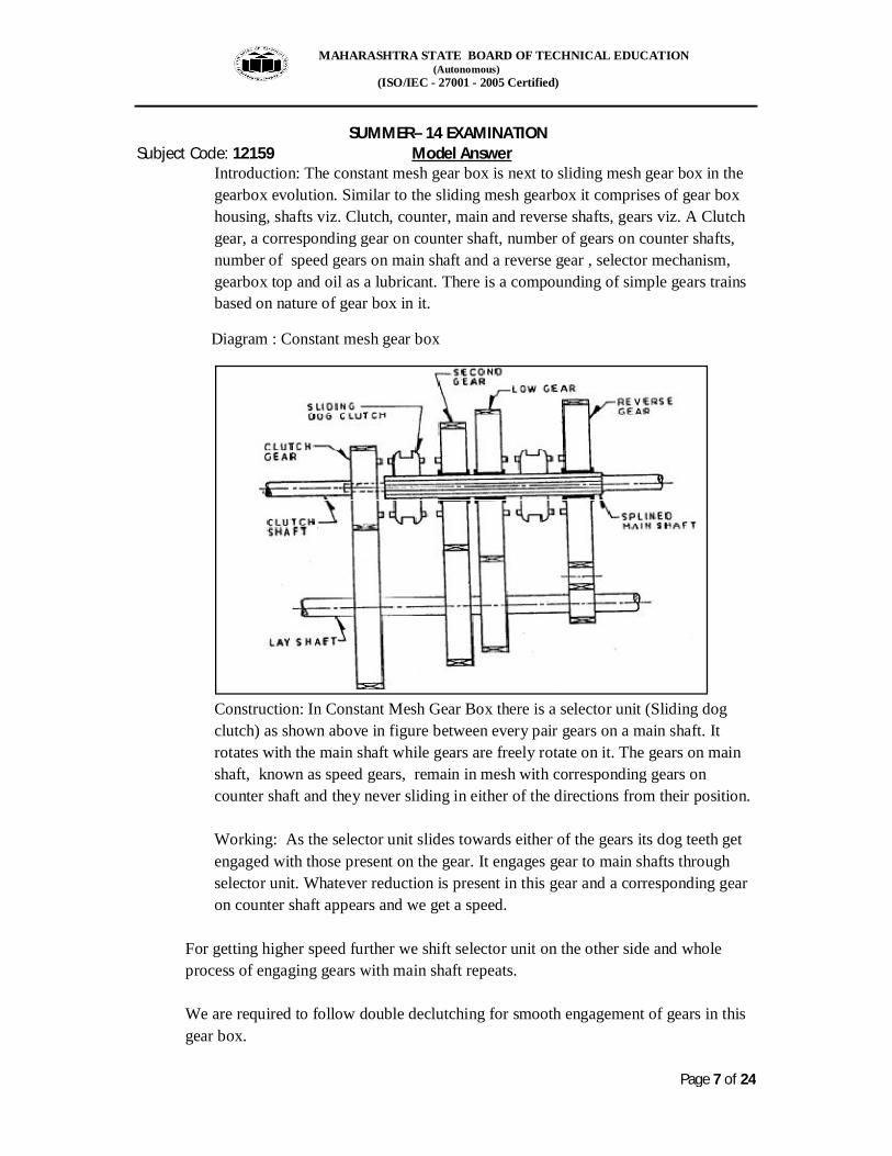
Introduction: The constant mesh gear box is next to sliding mesh gear box in the gearbox evolution. Similar to the sliding mesh gearbox it comprises of gear box housing, shafts viz. Clutch, counter, main and reverse shafts, gears viz. A Clutch gear, a corresponding gear on counter shaft, number of gears on counter shafts, number of speed gears on main shaft and a reverse gear , selector mechanism, gearbox top and oil as a lubricant. There is a compounding of simple gears trains based on nature of gear box in it.
Diagram : Constant mesh gear box
Construction: In Constant Mesh Gear Box there is a selector unit (Sliding dog clutch) as shown above in figure between every pair gears on a main shaft. It rotates with the main shaft while gears are freely rotate on it. The gears on main shaft, known as speed gears, remain in mesh with corresponding gears on counter shaft and they never sliding in either of the directions from their position.
Working: As the selector unit slides towards either of the gears its dog teeth get engaged with those present on the gear. It engages gear to main shafts through selector unit. Whatever reduction is present in this gear and a corresponding gear on counter shaft appears and we get a speed.
For getting higher speed further we shift selector unit on the other side and whole process of engaging gears with main shaft repeats. We are required to follow double declutching for smooth engagement of gears in this gear box.
MAHARASHTRA STATE BOARD OF TECHNICAL EDUCATION (Autonomous) (ISO/IEC - 27001 - 2005 Certified) SUMMER– 14 EXAMINATION Subject Code: 12159 Model Answer
Page 8 of 24
d) Why suspension is necessary in automobile? List four factor( 01 mark for each
factor, any our factors)
Need of suspension in motor vehicle:
1) To absorb and damps various vibrations, oscillations and shocks 2) To transmit braking and driving torque to body frame 3) To support the body on axles 4) To provide appropriate road grip 5) To avoid excessive rolling, pitching and bouncing 6) To provide stability on slopes and turns 7) To provide maximum comfort to the driver and passanger
e) Describe with a neat sketch the construction and working of a leaf spring ( 02 marks for sketch, 02 marks for working)
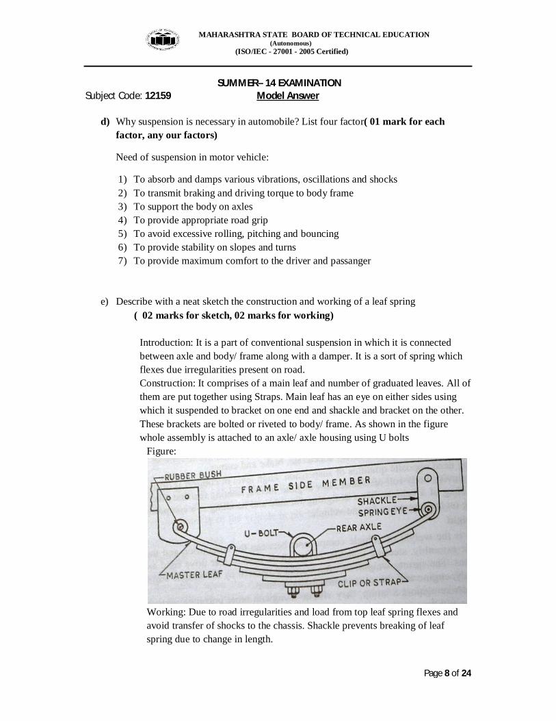
Introduction: It is a part of conventional suspension in which it is connected between axle and body/ frame along with a damper. It is a sort of spring which flexes due irregularities present on road. Construction: It comprises of a main leaf and number of graduated leaves. All of them are put together using Straps. Main leaf has an eye on either sides using which it suspended to bracket on one end and shackle and bracket on the other. These brackets are bolted or riveted to body/ frame. As shown in the figure whole assembly is attached to an axle/ axle housing using U bolts
Figure:
Working: Due to road irregularities and load from top leaf spring flexes and avoid transfer of shocks to the chassis. Shackle prevents breaking of leaf spring due to change in length.
MAHARASHTRA STATE BOARD OF TECHNICAL EDUCATION (Autonomous) (ISO/IEC - 27001 - 2005 Certified) SUMMER– 14 EXAMINATION Subject Code: 12159 Model Answer
Page 9 of 24
f) Explain requirements of steering system. ( Four marks for appropriate answer) Steering system is one of the active safety systems present in every motor vehicle. It provides safety from occurrence of an accident to the vehicle by keeping control over its direction. It is supposed to meet following requirements: -
1. Steer ability 2. Direction stability 3. Simple in construction 4. Simple to maintain 5. Keep road feel of a driver intact 6. Less efforts 7. Irreversible 8. convenience
Q. 3 attempt any FOUR of the following
a) Define ( one mark for each definition ) i. Caster – It is an angle made by king pin with vertical line as observed in the plane
of the front wheel ii. Camber- It is an angle between vertical line and tilt of wheel as observed from the
front side of the vehicle iii. Kingpin inclination- It is an angle subtended by kingpin with vertical when
observed it from a front side of the vehicle iv. Toe in- The extent to which front end of the front wheel is inside with reference
to its rear end is called as toe in.
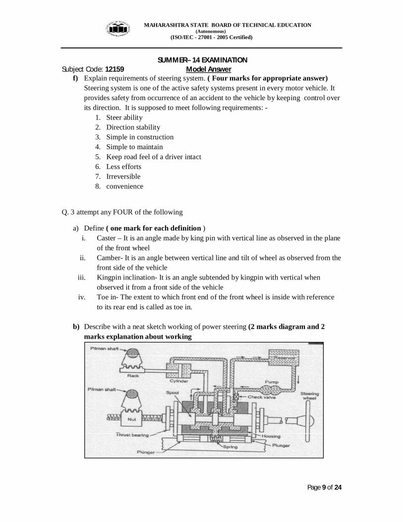
b) Describe with a neat sketch working of power steering (2 marks diagram and 2 marks explanation about working
MAHARASHTRA STATE BOARD OF TECHNICAL EDUCATION (Autonomous) (ISO/IEC - 27001 - 2005 Certified) SUMMER– 14 EXAMINATION Subject Code: 12159 Model Answer
Page 10 of 24
Working: When load of the vehicle increases, the steering effort required to turn the vehicle also increases. In case of heavy duty vehicles the steering force may be beyond the limit of driver or to follow the sharp turns of road quick steering effect is required. In all such a circumstances the power steering becomes more useful. Power steering takes the assistance of hydraulic power to reduce steering efforts. Power steering is operated by a oil under pressure.
The small movement of steering wheel actuates a valve so that the fluid under pressure from the reservoir enters in to the hydraulic cylinder whose piston operates steering linkage to steer vehicle in desired direction.
There are two types of hydraulic steering system i) Integral type – in this power operating assembly is a part of steering gear ii) Linkage type – in this power operating assembly is a part of steering linkage.
Integral type power steering system – Integral type power steering consists of a solid cylinder in which two grooves are cut to form valve spool. Valve spool slides in housing. The system is filled with oil. The reservoir always keeps the system filled with oil. The pump which is driven by engine power delivers oil under pressure in the central part of the cylinder. When vehicle is pitching in straight direction the oil going to the central portion of cylinder is sent back to reserviour as shown in fig. when vehicle is taking a turn the return lines to reservoir are closed and the pressurised oil is sent to the steering actuating cylinder to have turning of vehicle.
Appropriate fig. and linkage type power steering may be given full marks.
c) Describe construction of lead acid battery. ( Four marks for appropriate answer)
Battery is a reservoir of electric energy on every vehicle. It charges and discharges as it receives current from alternator and gives current to various consumers. There is a conversion of chemical energy into electrical energy that takes place while discharging of the battery while during charging electrical current supplied to it gets converted into chemical energy. Lead acid battery consists of following parts 1. Battery casing- 2. Battery Cover- It covers battery from top. It contains vent plugs and battery poles 3. Battery cells 4. Electrodes – positive and negative plates 5. Separator plates 6. Electrolytes – H2So4 + water 7. Plate strap
MAHARASHTRA STATE BOARD OF TECHNICAL EDUCATION (Autonomous) (ISO/IEC - 27001 - 2005 Certified) SUMMER– 14 EXAMINATION Subject Code: 12159 Model Answer
Page 11 of 24
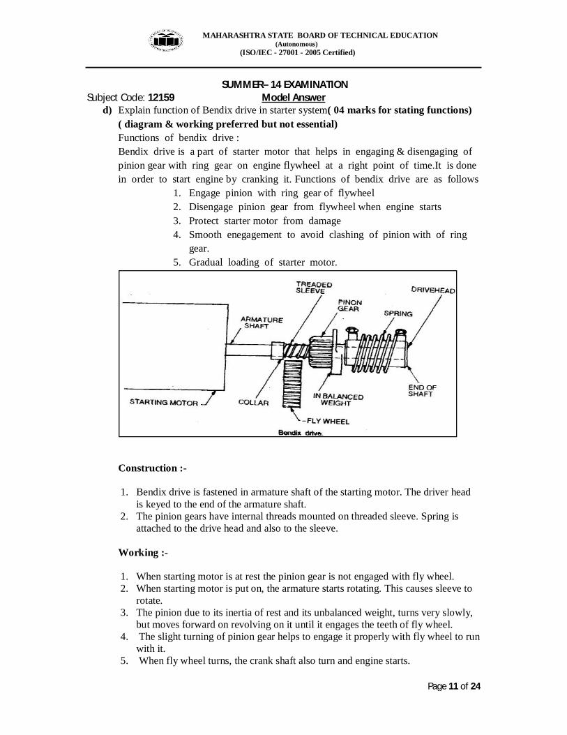
d) Explain function of Bendix drive in starter system( 04 marks for stating functions) ( diagram & working preferred but not essential) Functions of bendix drive : Bendix drive is a part of starter motor that helps in engaging & disengaging of pinion gear with ring gear on engine flywheel at a right point of time.It is done in order to start engine by cranking it. Functions of bendix drive are as follows
1. Engage pinion with ring gear of flywheel 2. Disengage pinion gear from flywheel when engine starts 3. Protect starter motor from damage 4. Smooth enegagement to avoid clashing of pinion with of ring
gear. 5. Gradual loading of starter motor.
Construction :- 1. Bendix drive is fastened in armature shaft of the starting motor. The driver head
is keyed to the end of the armature shaft. 2. The pinion gears have internal threads mounted on threaded sleeve. Spring is
attached to the drive head and also to the sleeve. Working :- 1. When starting motor is at rest the pinion gear is not engaged with fly wheel. 2. When starting motor is put on, the armature starts rotating. This causes sleeve to
rotate. 3. The pinion due to its inertia of rest and its unbalanced weight, turns very slowly,
but moves forward on revolving on it until it engages the teeth of fly wheel. 4. The slight turning of pinion gear helps to engage it properly with fly wheel to run
with it. 5. When fly wheel turns, the crank shaft also turn and engine starts.
MAHARASHTRA STATE BOARD OF TECHNICAL EDUCATION (Autonomous) (ISO/IEC - 27001 - 2005 Certified) SUMMER– 14 EXAMINATION Subject Code: 12159 Model Answer
Page 12 of 24
As engine has started, the pinion is turned by engine much faster than when started by starting motor. This caused pinion gear to turn back on thread sleeve making disengaged with the fly wheel.
e) Explain colour codes used for wiring in the lighting system. ( four marks for appropriate answer)
Electricals system uses colour code in order to attend break down maintenance easily. Lighting system, which illuminates road in front of a vehicle in the night, also follow certain standard practice in selecting wires for connecting various lamps and bulbs in particular to a battery. It is given as follows: - 6. Head Light – Blue 7. Fog lamp - Red 8. Flashing direction Indicator- Yellow, Green 9. Tail lamp – Green with purple tracer 10. Name plates -red 11. Instrument Cluster -red
Q. 4 a) Attempt any THREE of the following
i) Explain with a net sketch the circuit diagram of spark ignition system ( 02 marks for sketch,02 marks for explanation)
A system that provides a spark of high intensity at an appropriate moment of time is called as spark ignition system. It is an spark Ignition (Si) engine which needs such system and it has various formed based on source of power, method of triggering, mean for advancing and distributing spark.
Figure given below represents battery ignition system which comprises of following:- 1. Battery as source of power 2. Ignition coil as a step up transformer 3. CB point as a trigger mechanism 4. Speed and load mechanisms as spark advance mechanisms 5. Distributor supply high voltage to various spark plug as per firing order
Working; as ignition key is put on ‘On’ condition a current passes through primary circuit of HT coil and circuit completes at CB point present in the distributor. The distributor contains rotor, centrifugal spark mechanism, vacuum spark advance mechanism and cap containing central and cylinder specific terminals. A shaft on which rotor is attached at the top have a cam in between

MAHARASHTRA STATE BOARD OF TECHNICAL EDUCATION (Autonomous) (ISO/IEC - 27001 - 2005 Certified) SUMMER– 14 EXAMINATION Subject Code: 12159 Model Answer
Page 13 of 24
which makes and breaks CB point. Spark plug lead starts from cap and spark plugs are attached at other end.
HT coil contains secondary coil for inducing voltage which is finally connected to central electrode of the cap.
As current flows from battery to earth terminals of the distributor through primary coil and CB point the circuit completes. Due rotation of distributor shaft a cam breaks circuit to induce high voltage in secondary of HT coil at given time. It is supplied to distributor at centre which is distributed to different spark plugs as per firing order.
This system is known battery ignition or spark ignition system.
Figure
ii) Interpret the automobile market in India (Inclusion of Key words viz. socio economic development, LPG, Multinational companies and list of companies four in each sub-sector should get full marks) Automobile sector contributes in socio economical development of nation by generating employment on one side and contributing to gross domestic product by paying taxes. It is true in case of India also. Since adoption of Liberalization, privatization and globalisation (LPG) policy in 1991 Indian market witnessed entry of many multinational companies in each area. It is the competitive market in which following companies are trying to increase their market share in respective sub sector.
Two wheeler sector i. Hero Motocorp
ii. Bajaj Auto Ltd iii. TVS Motor Co Ltd iv. Honda Scooters and Motorcycles
MAHARASHTRA STATE BOARD OF TECHNICAL EDUCATION (Autonomous) (ISO/IEC - 27001 - 2005 Certified) SUMMER– 14 EXAMINATION Subject Code: 12159 Model Answer
Page 14 of 24
v. Suzuki vi. Enfield India
vii. Yamaha India viii. Mahindra Two wheeler
Four wheeler ix. TML PCBU x. Maruti Udyog Ltd
xi. Hyundai Motor Co xii. Kirloskar Toyota Motors Ltd
xiii. Mahindra & Mahindra xiv. Honda Siel xv. Hidustan Motors
xvi. Fiat India xvii. Chevrolet b) Commercial vehicles
i. TML CVBU ii. Ashok Leyland Ltd
iii. Swaraj Mazda Ltd iv. Eicher v. Bharat Benz
vi. Volvo India vii. Asia Motor Works (AMW)
viii. Mahindra Nevistar c) Special Purpose vehicle
i. Mahindra Tractor ii. John deere
iii. Punjab Tractor iv. Tafe v. Swaraj
vi. Eicher vii. Kuboto
viii. L&T Komatsu ix. L&T Case x. BEML
xi. Caterpiller
In a true sense Indian auto market is buyers market
iii) Sketch and explain fuel level gauge: (02 marks for sketch, 02 marks for explanation)
Figure:
MAHARASHTRA STATE BOARD OF TECHNICAL EDUCATION (Autonomous) (ISO/IEC - 27001 - 2005 Certified) SUMMER– 14 EXAMINATION Subject Code: 12159 Model Answer
Page 15 of 24
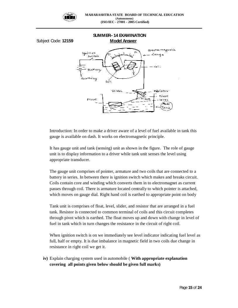
Introduction: In order to make a driver aware of a level of fuel available in tank this gauge is available on dash. It works on electromagnetic principle. It has gauge unit and tank (sensing) unit as shown in the figure. The role of gauge unit is to display information to a driver while tank unit senses the level using appropriate transducer. The gauge unit comprises of pointer, armature and two coils that are connected to a battery in series. In between there is ignition switch which makes and breaks circuit. Coils contain core and winding which converts them in to electromagnet as current passes through coil. There is armature located centrally to which pointer is attached, which moves on gauge dial. Right hand coil is earthed to appropriate point on body Tank unit is comprises of float, level, slider, and resistor that are arranged in a fuel tank. Resistor is connected to common terminal of coils and this circuit completes through pivot which is earthed. The float moves up and down with change in level of fuel in tank which in turn changes the resistance in the circuit of right coil. When ignition switch is on we immediately see level indicator indicating fuel level as full, half or empty. It is due imbalance in magnetic field in two coils due change in resistance in right coil we get it.
iv) Explain charging system used in automobile ( With appropriate explanation covering all points given below should be given full marks)
MAHARASHTRA STATE BOARD OF TECHNICAL EDUCATION (Autonomous) (ISO/IEC - 27001 - 2005 Certified) SUMMER– 14 EXAMINATION Subject Code: 12159 Model Answer
Page 16 of 24
Charging system is a part of a overall electrical system of motor vehicle which ensures that battery remains in charged state in any given situation. It comprises of following: - 1) Battery- Gets charged as it avails DC supply from rectifier 2) Rectifier- It is full wave three phase rectifier that is used in every vehicle 3) Regulator- It regulates current and voltage to the battery by regulating field
current 4) Alternator- Stator and rotor – Converts mechanical energy made available by
engine into electrical energy as per the principle of induction. 5) Relevant Electric circuit
b) Attempt any ONE of the following
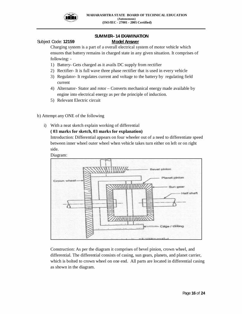
i) With a neat sketch explain working of differential ( 03 marks for sketch, 03 marks for explanation) Introduction: Differential appears on four wheeler out of a need to differentiate speed between inner wheel outer wheel when vehicle takes turn either on left or on right side. Diagram:
Construction: As per the diagram it comprises of bevel pinion, crown wheel, and differential. The differential consists of casing, sun gears, planets, and planet carrier, which is bolted to crown wheel on one end. All parts are located in differential casing as shown in the diagram.
MAHARASHTRA STATE BOARD OF TECHNICAL EDUCATION (Autonomous) (ISO/IEC - 27001 - 2005 Certified) SUMMER– 14 EXAMINATION Subject Code: 12159 Model Answer
Page 17 of 24
Working: When a vehicle follows straight ahead path, wheels on both sides are subjected to same rolling resistance. In that situation cage, planet carrier, and planets ratites along with crown wheel and this whole assembly makes sun gears on either side to rotate as if planets gears welded to the sun gears. There is no relative motion among planets and planet carrier. While as the vehicle takes turn the inner wheel is subjected to relatively higher rolling resistance than outer wheel. This lack of balance makes planets to rotate about planet carrier and in opposite direction. Such action accelerates outer sun wheel and retards inner one. As sun gears are splined on half shafts and to whom wheels are attached on other side, the inner wheel starts rotating slower than outer wheel . As a result differential action occurs which enables wheels to negotiates curved path without scrubbing of tyres
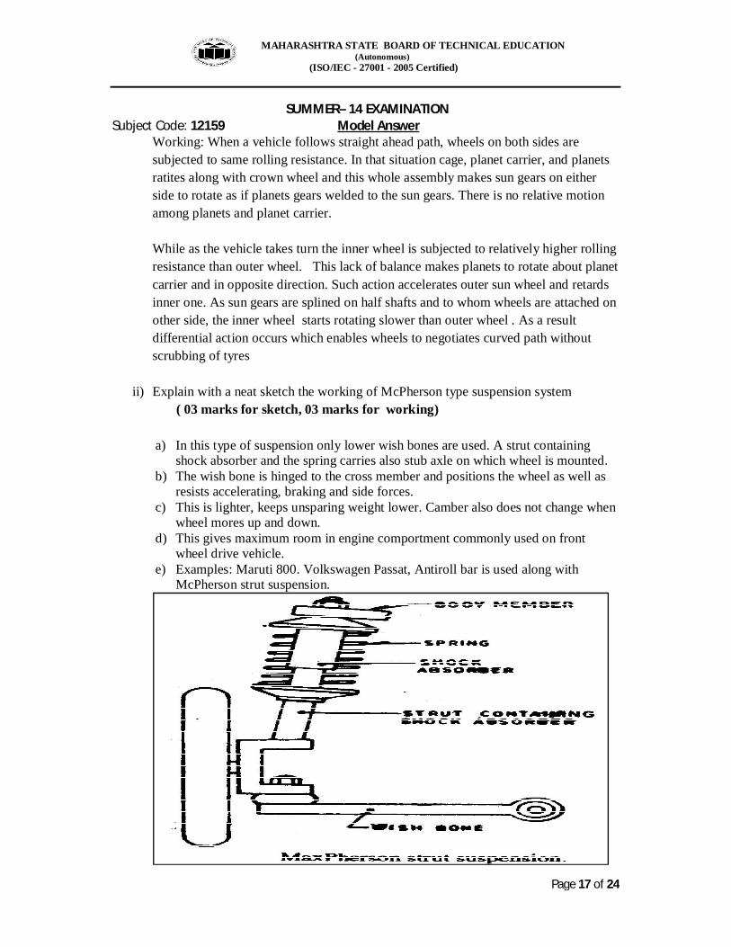
ii) Explain with a neat sketch the working of McPherson type suspension system ( 03 marks for sketch, 03 marks for working) a) In this type of suspension only lower wish bones are used. A strut containing
shock absorber and the spring carries also stub axle on which wheel is mounted. b) The wish bone is hinged to the cross member and positions the wheel as well as
resists accelerating, braking and side forces. c) This is lighter, keeps unsparing weight lower. Camber also does not change when
wheel mores up and down. d) This gives maximum room in engine comportment commonly used on front
wheel drive vehicle. e) Examples: Maruti 800. Volkswagen Passat, Antiroll bar is used along with
McPherson strut suspension.
MAHARASHTRA STATE BOARD OF TECHNICAL EDUCATION (Autonomous) (ISO/IEC - 27001 - 2005 Certified) SUMMER– 14 EXAMINATION Subject Code: 12159 Model Answer
Page 18 of 24
Q. 5 Attempt any TWO of the following
a) Explain the working of transfer case with a neat diagram and give its application. (02 mark for application, 03 marks for correct diagram and 03marks for working)
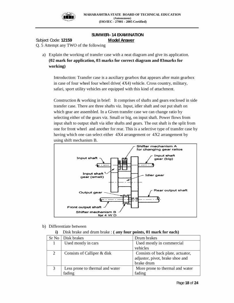
Introduction: Transfer case is a auxiliary gearbox that appears after main gearbox in case of four wheel four wheel drive( 4X4) vehicle. Cross country, military, safari, sport utility vehicles are equipped with this kind of attachment. Construction & working in brief: It comprises of shafts and gears enclosed in side transfer case. There are three shafts viz. Input, idler shaft and out put shaft on which gear are assembled. In a Given transfer case we can change ratio by selecting either of the gears viz. Small or big, on input shaft. Power flows from input shaft to output shaft via idler shafts and gears. The out shaft is the split from one for front wheel and another for rear. This is a selective type of transfer case by having which one can select either 4X4 arrangement or 4X2 arrangement by using shift mechanism B.
b) Differentiate between i) Disk brake and drum brake : ( any four points, 01 mark for each)
Sr No Disk brakes Drum brakes 1 Used mostly in cars Used mostly in commercial
vehicles 2 Consists of Calliper & disk Consists of back plate, actuator,
adjustor, pivot, brake shoe and brake drum
3 Less prone to thermal and water fading
More prone to thermal and water fading
MAHARASHTRA STATE BOARD OF TECHNICAL EDUCATION (Autonomous) (ISO/IEC - 27001 - 2005 Certified) SUMMER– 14 EXAMINATION Subject Code: 12159 Model Answer
Page 19 of 24
4 Simple in construction Relatively complex in construction 5 Externally contracting type Internally expanding type 6 Easy to maintain Relatively difficult to maintain 7 Preferred at front brake Remain at rear brake
ii) Mechanical and pneumatic brakes ( any four points, 01 mark for each)
Sr No Mechanical brakes Pneumatic brakes 1 Apply system is a mechanical linkage Apply system is air valve 2 Mechanical linkage in terms of lever
or cable is a transmission system Air pipes carrying air from air valve to brake chamber is a transmission system
3 Cam, wedge etc are actuators Spring brake chamber, spring brake actuator are actuators
4 Adjuster is mechanical in nature Adjuster is pneumatic and mechanical
5 Need to introduce compensation Compensation is in built 6 More reaction time Less reaction time 7 More maintenance Less maintenance
c) Explain typical wiring diagram of automobile with a neat sketch
MAHARASHTRA STATE BOARD OF TECHNICAL EDUCATION (Autonomous) (ISO/IEC - 27001 - 2005 Certified) SUMMER– 14 EXAMINATION Subject Code: 12159 Model Answer
Page 20 of 24
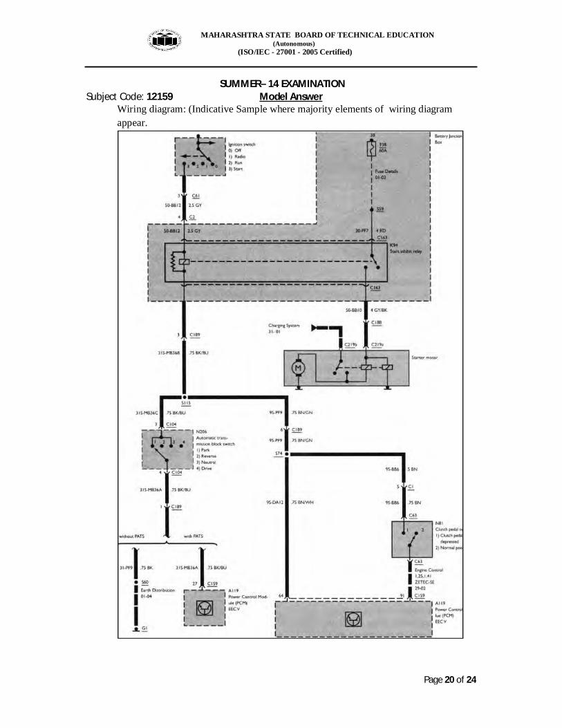
Wiring diagram: (Indicative Sample where majority elements of wiring diagram appear.
MAHARASHTRA STATE BOARD OF TECHNICAL EDUCATION (Autonomous) (ISO/IEC - 27001 - 2005 Certified) SUMMER– 14 EXAMINATION Subject Code: 12159 Model Answer
Page 21 of 24
Description: Above is a typical wiring diagram of starting system. It comprises of fuses, relays, switches, conductors and ECU. It shows colour code of wires used in connecting various units and also terminals in the form of numbers. It also shows gauges or sizes of wires used in connecting them. ( 04 marks for diagram, 04 marks for description)
Q. 6 Attempt any Four of the following
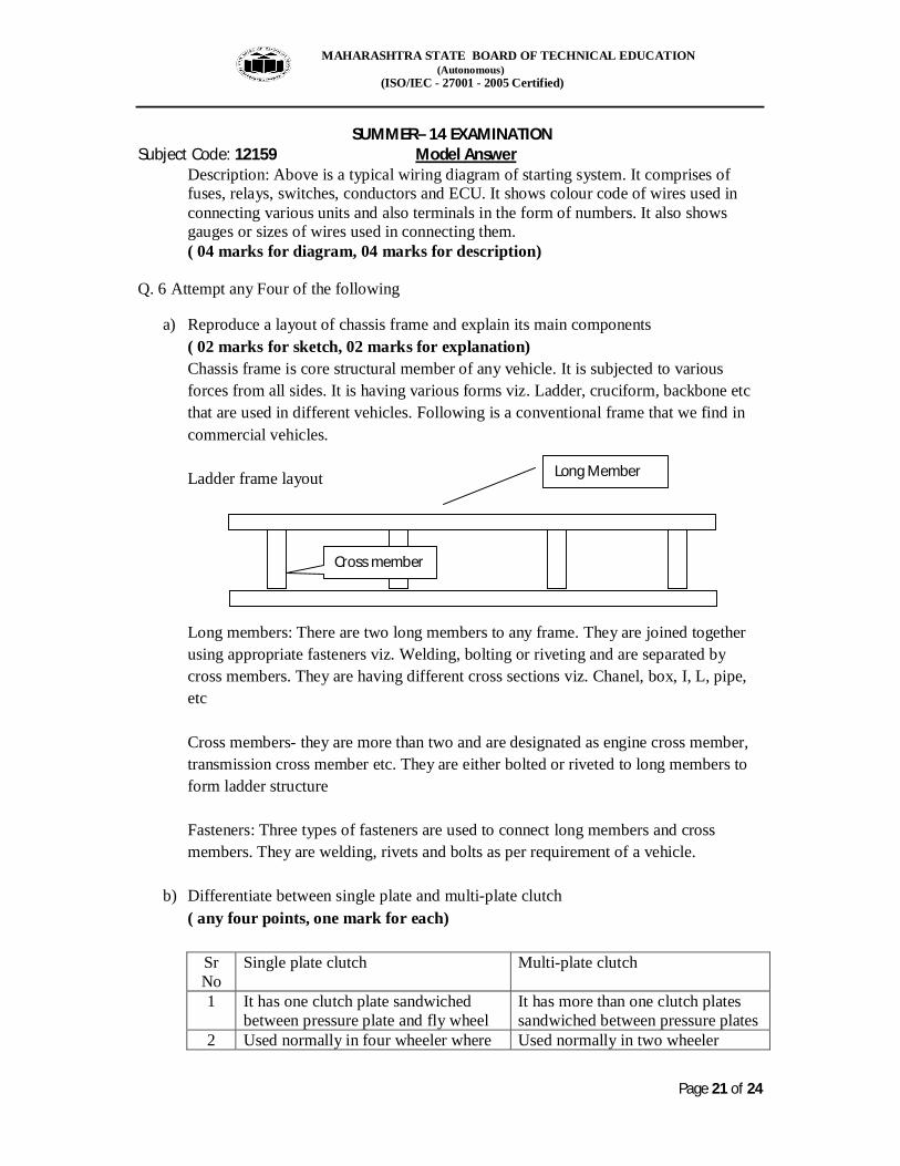
a) Reproduce a layout of chassis frame and explain its main components ( 02 marks for sketch, 02 marks for explanation) Chassis frame is core structural member of any vehicle. It is subjected to various forces from all sides. It is having various forms viz. Ladder, cruciform, backbone etc that are used in different vehicles. Following is a conventional frame that we find in commercial vehicles. Ladder frame layout Long members: There are two long members to any frame. They are joined together using appropriate fasteners viz. Welding, bolting or riveting and are separated by cross members. They are having different cross sections viz. Chanel, box, I, L, pipe, etc Cross members- they are more than two and are designated as engine cross member, transmission cross member etc. They are either bolted or riveted to long members to form ladder structure Fasteners: Three types of fasteners are used to connect long members and cross members. They are welding, rivets and bolts as per requirement of a vehicle.
b) Differentiate between single plate and multi-plate clutch ( any four points, one mark for each)
Sr No
Single plate clutch Multi-plate clutch
1 It has one clutch plate sandwiched between pressure plate and fly wheel
It has more than one clutch plates sandwiched between pressure plates
2 Used normally in four wheeler where Used normally in two wheeler
Long Member
Cross member

MAHARASHTRA STATE BOARD OF TECHNICAL EDUCATION (Autonomous) (ISO/IEC - 27001 - 2005 Certified) SUMMER– 14 EXAMINATION Subject Code: 12159 Model Answer
Page 22 of 24
area available for transfer of torque is more
where area available for transfer torque is less
3 Simple in construction Relatively complex in construction 4 Normally dry in nature Normally wet in nature 5 Clutch lining used is asbestos based Clutch lining used is cork based 6 Easy to maintain Relatively difficult to maintain
c) Differentiate between live rear axle and dead rear axle
( any four points, one mark for each) Sr No Live rear axle Dead rear axle
1 Transmits power to rear wheels Wheels are attached 2 It has three types viz. Semi floating,
three quarter floating and full floating based on arrangements of axle and casing
No such specific type
3 Present in FERWD vehicle layout and RERWD
Present in FEFWD vehicle layout and REFWD vehicle layout
4 Differential is present at the centre to divert power through 90 degree
No need of differential
5 Differential is required to differentiate between inner and outer wheel regarding speed
No need of differentiating action as wheels are attached to both the end using bearings
6 Experiences end torque reaction in both the actions viz. Drive and braking
End torque reaction only during braking
d) What is wheel balancing and wheel alignment? ( 2 marks each with keywords)
i) Wheel balancing: It is a process that ensures wheel spins truely as they are fitted
on a vehicle. In case wheel are not spinning properly then there are problems like uneven tyre wear, a vehicle pulling on one side, excessive bouncing of a vehicle, wheel shimmy etc which we face. To avoid them this is done. Wheel balancing means balancing wheel around axis around which it rotates. We have two types of balancing viz. Static balancing and dynamic balancing. Wheel balancing machines are used to carry out this act.
ii) Wheel alignment: It is a process of aligning wheels with respect to vehicle geometry based on some angles and dimensions. It also ensures uniform tyre wheel and vehicle dynamic performance. A vehicle gets steer ability and direction stability based on caster angle, camber angle, kingpin inclination, included angle, toe in and toe out. Over a period of time as the vehicle moves on road it is subjected to abuse and these dimensions and angles get changed. It affects
MAHARASHTRA STATE BOARD OF TECHNICAL EDUCATION (Autonomous) (ISO/IEC - 27001 - 2005 Certified) SUMMER– 14 EXAMINATION Subject Code: 12159 Model Answer
Page 23 of 24
manoeuvrability of the vehicle. In order to put them in order this process is followed after every six months in case vehicles with independent suspension. Wheel alignment machines are used to check all these angles and dimensions.
e) Illustrate with a neat sketch of radial ply tyre and cross ply tyres ( one mark each for
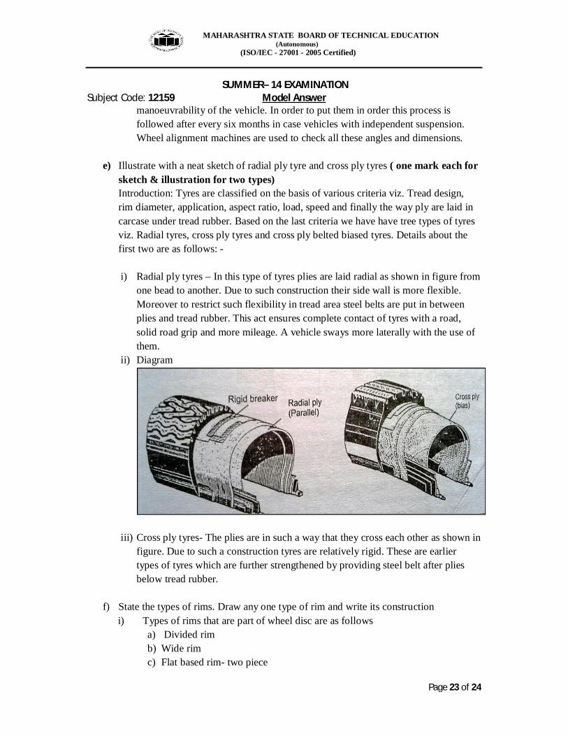
sketch & illustration for two types) Introduction: Tyres are classified on the basis of various criteria viz. Tread design, rim diameter, application, aspect ratio, load, speed and finally the way ply are laid in carcase under tread rubber. Based on the last criteria we have have tree types of tyres viz. Radial tyres, cross ply tyres and cross ply belted biased tyres. Details about the first two are as follows: - i) Radial ply tyres – In this type of tyres plies are laid radial as shown in figure from
one bead to another. Due to such construction their side wall is more flexible. Moreover to restrict such flexibility in tread area steel belts are put in between plies and tread rubber. This act ensures complete contact of tyres with a road, solid road grip and more mileage. A vehicle sways more laterally with the use of them.
ii) Diagram
iii) Cross ply tyres- The plies are in such a way that they cross each other as shown in figure. Due to such a construction tyres are relatively rigid. These are earlier types of tyres which are further strengthened by providing steel belt after plies below tread rubber.
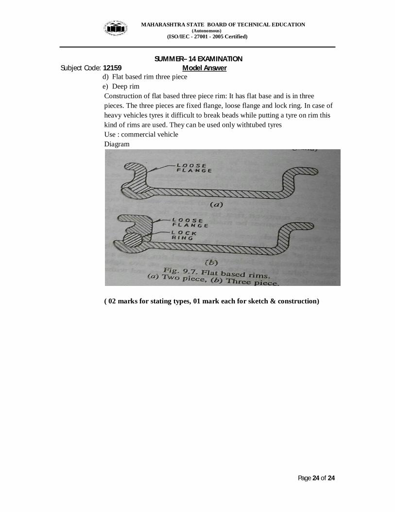
f) State the types of rims. Draw any one type of rim and write its construction i) Types of rims that are part of wheel disc are as follows
a) Divided rim b) Wide rim c) Flat based rim- two piece
MAHARASHTRA STATE BOARD OF TECHNICAL EDUCATION (Autonomous) (ISO/IEC - 27001 - 2005 Certified) SUMMER– 14 EXAMINATION Subject Code: 12159 Model Answer
Page 24 of 24
d) Flat based rim three piece e) Deep rim Construction of flat based three piece rim: It has flat base and is in three pieces. The three pieces are fixed flange, loose flange and lock ring. In case of heavy vehicles tyres it difficult to break beads while putting a tyre on rim this kind of rims are used. They can be used only withtubed tyres Use : commercial vehicle Diagram
( 02 marks for stating types, 01 mark each for sketch & construction)