main spindle bearings - ntnglobal.com · ntn main spindle bearings 211 ntn specifies the accuracies...
TRANSCRIPT

NTN Main Spindle Bearings
209
Main Spindle Bearings
10. Cylindrical Roller Bearings CONTENTS
10. Cylindrical roller bearings ……………………………………………………210〜237q Double-row cylindrical roller bearings ………………………………………210
w Single-row cylindrical roller bearings …………………………………………210
e Bearing designations ………………………………………………………………211
r Accuracy of tapered bore …………………………………………………………211
t Accuracy of cylindrical roller bearings ………………………………………212
y Radial internal clearance of cylindrical roller bearings……………………214
u Recommended fit of high-precision cylindrical roller bearings…………216
i Recommended lubrication specifications ……………………………………217
o Ultra high speed double row cylindrical roller bearings
NN30HSRT6 type ……………………………………………218
!0 Ultra high-speed single row cylindrical roller bearings
N10HSRT6 type………………………………………………220
!1 Eco-friendly air-oil lubricated ultra high speed single row cylindrical
roller bearings N10HSLT6 type ………………………………………………222
!2 Dimension tables for cylindrical roller bearingsDouble-row cylindrical roller bearings…………………………………………224High speed single-row cylindrical roller bearings …………………………230Ultra high-speed single row cylindrical roller bearings……………………234Eco-friendly ultra high-speed single row cylindrical roller bearings …236
!3 Taper gage and internal clearance adjustment gage
for NTN precision cylindrical roller bearings ………………………………238
!4 Dimension tables for taper gage ………………………………………………238
!5 Dimension table for mounted internal clearance adjustment gage ……239

210
10. Cylindrical Roller Bearings
In a cylindrical roller bearing, the rollers and racewaysare in linear contact. Consequently this type of bearingcan support a larger radial load than a point-contact ballbearing. Also, its structure is suitable for high-speedoperation.A cylindrical roller bearing used for the main spindle
of a machine tool can have either a double- or single-row configuration, and certain variants have a taperedbore so the radial internal clearance can be adjusted.
Double-row cylindrical roller bearings are available intwo types, NN and NNU, and two series, 30 and 49.The rollers in the NN type bearing are guided by theribs of the inner ring. The rollers in the NNU typebearing are guided by the ribs of the outer ring.Bearings are available with either a tapered bore type(which allows adjustment of radial internal clearance ofbearing) or a standard cylindrical bore.The bearings come in two types, standard type and
high-speed HS type. Standard cage is machined brass.
Single-row cylindrical roller bearings are available intwo types, high-speed N10HS type and ultra high-speed N10HSRT6 type. The N10HS type bearingshave high-strength machined brass cages, while theN10HSR type bearings have special molded resincages, which can be used for both grease lubricationand air-oil lubrication. The eco-friendly N10HSLT6 typeis a variation from the high-speed N10HSRT6 typebearing and can be used with air-oil lubrication only.
① Double-row cylindrical roller bearings
NTN Main Spindle Bearings
② Single-row cylindrical roller bearings
NN type
Tapered bore
Cylindrical bore
NNU type
Tapered bore
Cylindrical bore
Fig. 10.1
N10HS type N10HSR type
N10HSL type
Taperedbore
Cylindricalbore
Taperedbore
Cylindricalbore
Taperedbore
Cylindricalbore
Fig. 10.2

NTN Main Spindle Bearings
211
NTN specifies the accuracies of tapered boresconforming with JIS Classes 4 and 2 as shown below.Poor accuracies of the tapered bore lead tomisalignment of the inner ring, causing poorperformance, premature seizure and flaking. Use of ataper gauge is recommended for higher accuracy of themain spindle. Refer to "6 Handling of Bearings, ⑧ Taperedbore cylindrical roller bearing and main spindle taperangle" in the Technical Data section for moreinformation on taper angle.
③ Bearing designations
④ Accuracy of tapered bore
Precision class P5:JIS class 5 P2:JIS class 2 P4:JIS class 4 UP:Special high precision
Internal modification code No code:Standard specification HS:High speed specification HSR:Ultra High speed specificationBore diameter code
Bearing type code NN:Double row with ribbed inner ring NNU:Double row with ribbed outer ring
Dimension series code
External configuration code K:Tapered inner ring bore, taper ratio1/12 No code:Cylindrical inner ring boreNo code:Machined brass bore T6:Molded PEEK cage.
Internal clearance code See Table 10.4~10.6
Cage code T6:Molded PEEK cage (HSR type) No code:High strength machined brass cage
Internal modification code HS:High speed specification HSR:Ultra high speed specification
Bearing type code N:Single row with ribbed inner ring
NN 30 20 HS RT6 K C0NA P4
N 10 20 HSR T6 K C0NA P4 Spacer code (Eco- friendly nozzle)
Cage code T6:PEEK resin mold cage
Internal modification code
N 10 20 HSL T6 K C0NA P4 +TKZ
NN49, 30, NNU49 type
N10HS, N10HSR type N10HSL type
α α
φd+Δdmp
BB
φd1+Δd1mp
Δd1mp-Δdmp 2
φd1φd
Theoretical tapered bore Tapered bore having single plane mean bore diameter deviation
Tolerance of 1/12 taper angle 4˚46’18.8” +24” 0
α=2˚23’9.4”
d1=d+ B
Vdp:Single radial plane bore diameter variation Δdmp:Single plane mean bore diameter deviation
(at theoretical small end on tapered bore) Δd1mp:Single plane mean bore diameter deviation
(at theoretical large end on tapered bore) B:Nominal inner ring width
121
Fig. 10.3
d mm
Δdmp Δd1mp-Δdmp (approx.)
Vdp
maxover incl. high low high low
18
30
50
80
120
180
250
315
400
+10
+12
+15
+20
+25
+29
+32
+36
+40
0
0
0
0
0
0
0
0
0
+ 6
+ 7
+ 8
+10
+12
+14
-
-
-
0
0
0
0
0
0
-
-
-
+ 4
+ 5
+ 6
+ 7
+ 8
+ 9
+10
+12
+14
0
0
0
0
0
0
0
0
0
+3
+3.5
+4
+5
+6
+7
-
-
-
0
0
0
0
0
0
-
-
-
30
50
80
120
180
250
315
400
500
2.5
2.5
3
4
5
7
8
9
10
1.5
1.5
2
2.5
3.5
4.5
-
-
-
Note: NTN specification
Unit:μm
Class 4 Class 2
high low high low
Class 4 Class 2 Class 4 Class 2
Table 10.1 Tolerance of taper-bored bearings

NTN Main Spindle Bearings
212
⑤ Accuracy of cylindrical roller bearings
Table 10.2 Inner rings
Table 10.3 Outer rings
Nominal bore diameter
d mm
Deviation of mean bore diameter in a single plane
Δdmp
Class 5 Class 4 1 Class 2 1
Variation of bore diameter in a single plane
Vdsp
Diameter series 9
18
30 50 80
120 150 180
250 315 400
30
50 80
120
150 180 250
315 400 500
0
0 0 0
0 0 0
0 0 -
- 6
- 8 - 9 -10
-13 -13 -15
-18 -23 -
0
0 0 0
0 0 0
- - -
- 5
- 6 - 7 - 8
-10 -10 -12
- - -
0
0 0 0
0 0 0
- - -
6
8 9
10
13 13 15
18 23 -
5
6 7 8
10 10 12
― ― ―
2.5
2.5 4 5
7 7 8
― ― ―
-2.5
-2.5 -4 -5
-7 -7 -8
- - -
over incl. high low
high low high low
5
6 7 8
10 10 12
14 18 ―
4
5 5 6
8 8 9
― ― ―
2.5
2.5 4 5
7 7 8
― ― ―
3
4 5 5
7 7 8
9 12 ―
2.5
3 3.5 4
5 5 6
― ― ―
1.5
1.5 2 2.5
3.5 3.5 4
― ― ―
4
5 5 6
8 8
10
13 15 ―
3
4 4 5
6 6 8
― ― ―
2.5
2.5 2.5 2.5
2.5 5 5
― ― ―
Diameter series 0
Variation of mean bore diameter
Vdmp
Inner ring radial runout
Kia
Class 5 Class 4 Class 2max
Class 5 Class 4 Class 2max
Class 5 Class 4 Class 2max
Class 5 Class 4 Class 2max
1 The tolerance of bore diameter deviation Δds applicable to classes 4 and 2 is the same as the tolerance of single plane mean bore diameter deviation Δdmp.
Nominal bore diameter
D mm
Deviation of mean outside diameter in a single plane
ΔDmp
Variation of outside diameter in a single plane
VDsp
30 50
80 120 150
180 250 315
400 500 630
50 80
120 150 180
250 315 400
500 630 800
0 0
0 0 0
0 0 0
0 0 0
- 7 - 9
-10 -11 -13
-15 -18 -20
-23 -28 -35
0 0
0 0 0
0 0 0
- - -
- 6 - 7
- 8 - 9 -10
-11 -13 -15
- - -
0 0
0 0 0
0 0 0
- - -
7 9
10 11 13
15 18 20
23 28 35
6 7
8 9
10
11 13 15
- - -
4 4
5 5 7
8 8
10
- - -
- 4 - 4
- 5 - 5 - 7
- 8 - 8 -10
- - -
5 7
8 8
10
11 14 15
17 21 26
5 5
6 7 8
8 10 11
- - -
4 4
5 5 7
8 8
10
- - -
4 5
5 6 7
8 9
10
12 14 18
3 3.5
4 5 5
6 7 8
- - -
2 2
2.5 2.5 3.5
4 4 5
- - -
7 8
10 11 13
15 18 20
23 25 30
5 5
6 7 8
10 11 13
- - -
2.5 4
5 5 5
7 7 8
- - -
Variation of mean outside diameter
VDmp
Outer ring radial runout
Kea
2 The tolerance of outside diameter deviation ΔDs applicable to classes 4 and 2 is the same as the tolerance of mean single plane outside diameter deviation ΔDmp.
Class 5 Class 4 2 Class 2 2Diameter series 9
over incl. high low high low high low
Diameter series 0Class 5 Class 4 Class 2
maxClass 5 Class 4 Class 2
maxClass 5 Class 4 Class 2
maxClass 5 Class 4 Class 2
maxC

NTN Main Spindle Bearings
213
Width deviation
ΔBs
Single bearing
Width variation
VBs
5
5 6 7
8 8
10
13 15 ―
1.5
1.5 1.5 2.5
2.5 4 5
― ― ―
2.5
3 4 4
5 5 6
― ― ―
0
0 0 0
0 0 0
0 0 ―
-120
-120 -150 -200
-250 -250 -300
-350 -400 ―
0
0 0 0
0 0 0
― ― ―
-120
-120 -150 -200
-250 -300 -350
― ― ―
high low high low
Class 5 Class 5Class 4 Class 4Class 2 Class 2max
Class 5 Class 4 Class 2max
Perpendicularity of inner ring face
with respect to the bore Sd
8
8 8 9
10 10 11
13 15 ―
1.5
1.5 1.5 2.5
2.5 4 5
― ― ―
4
4 5 5
6 6 7
― ― ―
Unit:μm
Width deviation
ΔCs
All classes
Width variation
VCs
5 6
8 8 8
10 11 13
15 18 20
1.5 1.5
2.5 2.5 2.5
4 5 7
- - -
2.5 3
4 5 5
7 7 8
- - -
Identical to ΔBs relative to d on the same bearing.
Perpendicularity of outer ring outside surface with respect to the face
SD
8 8
9 10 10
11 13 13
15 18 20
1.5 1.5
2.5 2.5 2.5
4 5 7
- - -
4 4
5 5 5
7 8
10
- - -
Unit:μm
Class 5 Class 4 Class 2max
Class 5 Class 4 Class 2max
NTN Main Spindle Bearings
214
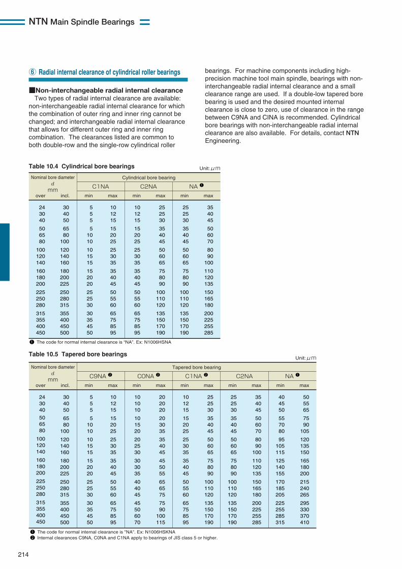
■Non-interchangeable radial internal clearance Two types of radial internal clearance are available:
non-interchangeable radial internal clearance for whichthe combination of outer ring and inner ring cannot bechanged; and interchangeable radial internal clearancethat allows for different outer ring and inner ringcombination. The clearances listed are common toboth double-row and the single-row cylindrical roller
⑥ Radial internal clearance of cylindrical roller bearings
Table 10.4 Cylindrical bore bearings
Nominal bore diameter d mm
Unit:μm
over min max min max min maxincl.
Cylindrical bore bearing
C1NA C2NA NA 1
24 30 40
50 65 80
100 120 140
160 180 200
225 250 280
315 355 400 450
30 40 50
65 80
100
120 140 160
180 200 225
250 280 315
355 400 450 500
10 12 15
15 20 25
25 30 35
35 40 45
50 55 60
65 75 85 95
10 12 15
15 20 25
25 30 35
35 40 45
50 55 60
65 75 85 95
25 25 30
35 40 45
50 60 65
75 80 90
100 110 120
135 150 170 190
25 25 30
35 40 45
50 60 65
75 80 90
100 110 120
135 150 170 190
35 40 45
50 60 70
80 90
100
110 120 135
150 165 180
200 225 255 285
5 5 5
5 10 10
10 15 15
15 20 20
25 25 30
30 35 45 50
1 The code for normal internal clearance is “NA”. Ex: N1006HSNA Table 10.5 Tapered bore bearings
Nominal bore diameter d mm
Unit:μm
over min max min max min maxincl.
Tapered bore bearing
C9NA 2 C0NA 2 C1NA 2
24 30 40
50 65 80
100 120 140
160 180 200
225 250 280
315 355 400 450
30 40 50
65 80
100
120 140 160
180 200 225
250 280 315
355 400 450 500
10 12 15
15 20 25
25 30 35
35 40 45
50 55 60
65 75 85 95
10 10 10
10 15 20
20 25 30
30 30 35
40 40 45
45 50 60 70
20 20 20
20 30 35
35 40 45
45 50 55
65 65 75
75 90
100 115
10 12 15
15 20 25
25 30 35
35 40 45
50 55 60
65 75 85 95
25 25 30
35 40 45
50 60 65
75 80 90
100 110 120
135 150 170 190
min max
C2NA
25 25 30
35 40 45
50 60 65
75 80 90
100 110 120
135 150 170 190
35 40 45
50 60 70
80 90
100
110 120 135
150 165 180
200 225 255 285
min max
NA 1
40 45 50
55 70 80
95 105 115
125 140 155
170 185 205
225 255 285 315
50 55 65
75 90
105
120 135 150
165 180 200
215 240 265
295 330 370 410
5 5 5
5 10 10
10 15 15
15 20 20
25 25 30
30 35 45 50
1 The code for normal internal clearance is "NA". Ex: N1006HSKNA 2 Internal clearances C9NA, C0NA and C1NA apply to bearings of JIS class 5 or higher.
bearings. For machine components including high-precision machine tool main spindle, bearings with non-interchangeable radial internal clearance and a smallclearance range are used. If a double-low tapered borebearing is used and the desired mounted internalclearance is close to zero, use of clearance in the rangebetween C9NA and CINA is recommended. Cylindricalbore bearings with non-interchangeable radial internalclearance are also available. For details, contact NTNEngineering.

NTN Main Spindle Bearings
215
■Interchangeable radial internal clearance (cylindrical bore)
Table 10.6
Nominal bore diameter d mm
Unit:μm
over min max min max min maxincl.
C2 CN (Normal)
C3
24 30 40
50 65 80
100 120 140
160 180 200
225 250 280
315 355 400 450
30 40 50
65 80
100
120 140 160
180 200 225
250 280 315
355 400 450 500
0 5 5
10 10 15
15 15 20
25 35 45
45 55 55
65 100 110 110
25 30 35
40 45 50
55 60 70
75 90
105
110 125 130
145 190 210 220
20 25 30
40 40 50
50 60 70
75 90
105
110 125 130
145 190 210 220
45 50 60
70 75 85
90 105 120
125 145 165
175 195 205
225 280 310 330
35 45 50
60 65 75
85 100 115
120 140 160
170 190 200
225 280 310 330
60 70 80
90 100 110
125 145 165
170 195 220
235 260 275
305 370 410 440
■Adjustment of clearance in tapered bore bearingsMounted internal clearance of a tapered bore bearing
can be adjusted by controlling the drive-up of thetapered bore onto the shaft. Two types of adjustingmethods area available: repeated adjustment of spacerwidth and adjustment with using a mounted internalclearance gauge. The clearance gauge is convenientfor mass-production. Refer to "6. Handling of Bearings,⑦ Clearance adjustment for cylindrical roller bearing,measurement with mounted internal clearance gage" inthe Technical Data section.

NTN Main Spindle Bearings
216
In order to maintain the high precision of a precisionbearing under dmn value is lower than 0.75×10⁶ the fitslisted in Tables 10.7 and 10.8 are recommended (dmn:pitch circle diameter across rolling elements [mm]multiplied by speed [min-1]).When the dmn value is lager than 0.75×10⁶ (dmn
value ≥ 0.75×10⁴), consult NTN Engineering about therecommended fit. Expansion of the inner ring due tocentrifugal force must be considered when determiningshaft fit.
■Fit of tapered bore bearingsWhen fitting a tapered bore bearing onto a shaft,
carefully and thoroughly adjust the fit of the taperedbore to the shaft to maintain high precision of thebearing.For details of taper angle adjustment refer to "6.
Handling of Bearings, ⑧ Cylindrical roller bearing andmain spindle taper angle" in the Technical Data section.
⑦ Recommended fit of high-precision cylindrical roller bearings
Nominal bore diameter
d mmFit between inner
ring and shaftFit between outer ring
and housingover incl.
18 30 50
80 120 180
250 315
30 50 80
120 180 250
315 400
0~ 4T 0~ 5T
1T~ 6T
1T~ 6T 2T~ 8T 2T~ 8T
3T~10T 4T~11T
Nominal bore diameter
D mmover incl.
30 50 80
120 150 180
250 315 400
50 80
120
150 180 250
315 400 500
0~3T 0~4T 0~4T
0~5T 0~5T 0~6T
0~7T 0~8T 0~9T
Note 1: Target the median value. T: Tight (Interference) fit Not applicable to tapered bore bearings
Note 1: Target the median value. T: Tight (Interference) fit
Unit:μm Unit:μmTable 10.7 Fit with shaft Table 10.8 Fit with housing
NTN Main Spindle Bearings
217
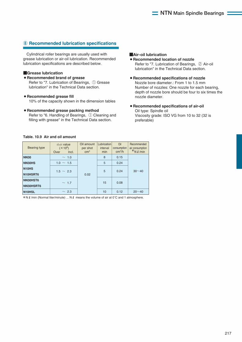
Cylindrical roller bearings are usually used withgrease lubrication or air-oil lubrication. Recommendedlubrication specifications are described below.
■Grease lubrication¡Recommended brand of grease
Refer to "7. Lubrication of Bearings, ① Greaselubrication" in the Technical Data section.
¡Recommended grease fill10% of the capacity shown in the dimension tables
¡Recommended grease packing methodRefer to "6. Handling of Bearings, ① Cleaning andfilling with grease" in the Technical Data section.
⑧ Recommended lubrication specifications
Table. 10.9 Air and oil amount
*NR/min (Normal liter/minute) ... NR means the volume of air at 0˚C and 1 atmosphere.
Recommended air consumption *NR/min
Bearing type
NN30
NN30HS
N10HS
N10HSRT6
NN30HST6
NN30HSRT6
N10HSL
dmn value (×106)
Over Incl.
~ 1.0
1.0 ~ 1.5
0.02
8
5
5
10
1.5 ~ 2.3 30~40
20~40 ~ 2.3
Oil amount per shot
cm3
Lubrication interval min
0.15
0.24
0.24
15 ~ 1.7 0.08
0.12
Oil consumption
cm3/h
■Air-oil lubrication¡Recommended location of nozzle
Refer to "7. Lubrication of Bearings, ② Air-oillubrication" in the Technical Data section.
¡Recommended specifications of nozzleNozzle bore diameter.: From 1 to 1.5 mmNumber of nozzles: One nozzle for each bearing,depth of nozzle bore should be four to six times thenozzle diameter.
¡Recommended specifications of air-oilOil type: Spindle oilViscosity grade: ISO VG from 10 to 32 (32 ispreferable)

218
NTN Main Spindle Bearings
NN30HSRT6 ultra high speed double row cylindricalroller bearings have higher operating speed with thesame level of rigidity and capacity as the conventionalseries.
Features1. Optimized internal design to realize high speed and
low temperature rise.2. Molded PEEK cage is used for high speed under
grease & air-oil lubrication and grease life.
⑨ Ultra high speed double row cylindrical roller bearings NN30HSRT6 type
Fig. 10.4 NN30HSRT6 type
■Permissible speed range
NN30HSRT6
0 0.2 0.4 0.6 0.8 1.0 1.2 1.4 1.6 1.8 2.0 2.2 2.4 2.6 2.8
Grease lubrication Air-oil lubrication
Notes) Permissible speed of each bearing (dmn value) varies depending on the specifications of the machine for which the bearing is used (motor drive system, cooling system, and construction around the bearing). Consider the optimal choice referring to the above guideline and contact NTN.
dmn value ×106
■Bearing design
Photo 10.1 PEEK cage
■Cage designCage is made of PEEK which is very light and strong.
(Photo 10.1)Smaller deformation by the centrifugal force is
realized by the lighten cage material and unproveddesign High speed operation is by the cage designimprovement. Grease life is extended by grease pocketin the cage.

219
NTN Main Spindle Bearings
■High speed testdmn value of 1.0 million under grease lubrication and 1.75 million under air-oil lubrication are realized by the
optimized internal design. (Fig 10.5, 10.6)
■Grease lifeOver 13800 hours continuous operation under grease lubrication is realized by the improved cage design at dmn
value of 1.0 million. (Fig. 10.7)
Fig. 10.5 Comparison of temperature rise (grease) Fig. 10.6 Comparison of temperature rise (air- oil)
Bearing Speed Mounted radial clearance Lubrication Grease type Jacket cooling
NN3020HSRT6K NN3020HST6K NN3020HSK (φ100×φ150×37) ~8000 min-1 -5 μm Grease lubrication MP-1 Yes
【Test conditions】
Bearing Speed Mounted radial clearance Lubrication
Oil Air Jacket cooling
NN3020HSRT6K NN3020HST6K NN3020HSK (φ100×φ150×37) ~15000 min-1 0 μm Air- Oil lubrication 0.02 mL/1shot Oil shot interval: 20min 30 NL/min Yes
【Test conditions】
0 0.25 0.5 0.75 1.0
0 2000 4000 6000 8000
25
20
15
10
5
0
Speed min-1
dmn value ×106
OR
tem
pera
ture
ris
e ˚
C
Speed min-1
0 1.00.5 1.5
dmn value ×106
OR
tem
pera
ture
ris
e ˚
C
0 5000 10000 15000
35
30
25
20
15
10
5
0
NN3020HSRT6K NN3020HST6K NN3020HSK
NN3020HSRT6K NN3020HST6K NN3020HSK
Bearing Speed Mounted radial clearance Lubrication Grease type Jacket cooling
NN3020HSRT6K NN3020HSK (φ100×φ150×37) 8000 min-1 -5 μm Grease lubrication MP-1 Yes
【Test conditions】
Duration, h
over 13800h
1500h
NN30 HSRT6K
NN30 HSK
More than 9 times
Fig. 10.7 Comparison of grease life

NTN Main Spindle Bearings
220
N10HSRT6 type cylindrical roller bearings have beendesigned for high-speed operation.
Features1. Optimized internal design allows high speed
operation and limits temperature increase.2. Special resin cage is suitable for high-speed
operation.
!0 Ultra high-speed single row cylindrical roller bearings N10HSRT6 type
Fig. 10.8 N10HSRT6 type
■Permissible speed range
N10HSRT6
0 0.2 0.4 0.6 0.8 1.0 1.2 1.4 1.6 1.8 2.0 2.2 2.4 2.6 2.8
Grease lubrication Air-oil lubrication
Notes) Permissible speed of each bearing (dmn value) varies depending on the specifications of the machine for which the bearing is used (motor drive system, cooling system, and construction around the bearing). Consider the optimal choice referring to the above guideline and contact NTN.
dmn value ×106
■Bearing specification
Fig. 10.9 Modification of lubrication system
■Simplified main spindle configuration/ adoption of simplified lubrication systemDue to an optimized internal structure, the N10HSR
type bearings can reliably run at a higher speed withgrease lubrication. The grease lubrication systemgreatly contributes to reduction in pollution of thesurrounding environments by virtually eliminating oilmist (Fig. 10.9).
■Simplified main spindle configuration/ simplified main spindle rear structureN10HSR (N10HSL) type high-speed cylindrical roller
bearings can replace angular contact ball bearing onthe rear side of the main spindle. This arrangementdecreases the number of bearing rows (two rows to onerow) and eliminates the ball slide mechanism, greatlycontributing to simplification of the rear structure (Fig.10.10).
Air-oil lubrication Grease lubrication
Capable of replacing air-oil lubricated bearings up to dmn value of 1,150,000.
Fig. 10.10 Simplified main spindle rear structure
w/ ball slide mechanism
w/o ball slide mechanism
Capable of replacing angular contact ball bearings up to dmn value of 2,300,000 [air-oil lubrication] or 1,150,000 [grease lubrication].

NTN Main Spindle Bearings
221
High-speed operation test with grease lubricationDue to an optimized internal design, the N10HSR type is capable of high-speed operation with dmn value of 1.15
million [grease lubrication] or 2.3 million [air-oil lubrication] (Figs. 10.11, 10.12, 10.13, 10.14).
Fig. 10.11 High-speed test results (grease lubrication without outer case cooling)
Fig. 10.12 High-speed test results (grease lubrication with outer case cooling)
Fig. 10.13 High-speed test results (air-oil lubrication without jacket cooling)
Fig. 10.14 High-speed test results (air-oil lubrication with jacket cooling)
0 0.5 1.0
0 2000 6000 8000 10000 12000 14000 160004000
20
18
16
14
12
10
8
6
4
2
0
Speed(min-1)
dmn value ×106
Tem
pera
ture
incr
ease
of
out
er r
ing
˚C
Tem
pera
ture
incr
ease
of
out
er r
ing
˚C
Tem
pera
ture
incr
ease
of
out
er r
ing
˚C
Tem
pera
ture
incr
ease
of
out
er r
ing
˚C
Test bearing Shaft speed Mounted radial clearance Lubrication Jacket cooling
N1011HSRT6 N1011HS (φ55×φ90×18) ~16000 min-1
0 μm Grease No
【Test conditions】
Test bearing Shaft speed Mounted radial clearance Lubrication Jacket cooling
【Test conditions】
N1011HSN1011HSRT6
0 0.5 1.0 1.5 2.0 2.5
0 5000 15000 20000 2500010000
50
40
30
20
10
0
Speed(min-1)
dmn value ×106
Test bearing Shaft speed Mounted radial clearance Lubrication
Oil consumption Air consumption Jacket cooling
N1016HSRT6 N1016HS (φ80×φ125×22) ~22000 min-1
0 μm Air-oil lubrication 0.02 mL/shot
(oil shot intervals, 5 min) 40 NL/min No
【Test conditions】
N1016HSN1016HSRT6
0 0.5 1.0 1.5 2.0 2.5
0 5000 15000 20000 2500010000
50
40
30
20
10
0
Speed(min-1)
dmn value ×106
Test bearing Shaft speed Mounted radial clearance Lubrication
Oil consumption Air consumption Jacket cooling
N1016HSRT6 N1016HS (φ80×φ125×22) ~22000 min-1
0 μm Air-oil lubrication 0.02 mL/shot
(oil shot intervals, 5 min) 40 NL/min Yes
【Test conditions】
N1016HSN1016HSRT6
0 0.5 1.0
0 2000 6000 8000 10000 12000 14000 160004000
10
9
8
7
6
5
4
3
2
1
0
Speed(min-1)
dmn value ×106
N1011HSRT6 N1011HS (φ55×φ90×18) ~16000 min-1 0 μm Grease Yes
N1011HSN1011HSRT6
NTN Main Spindle Bearings
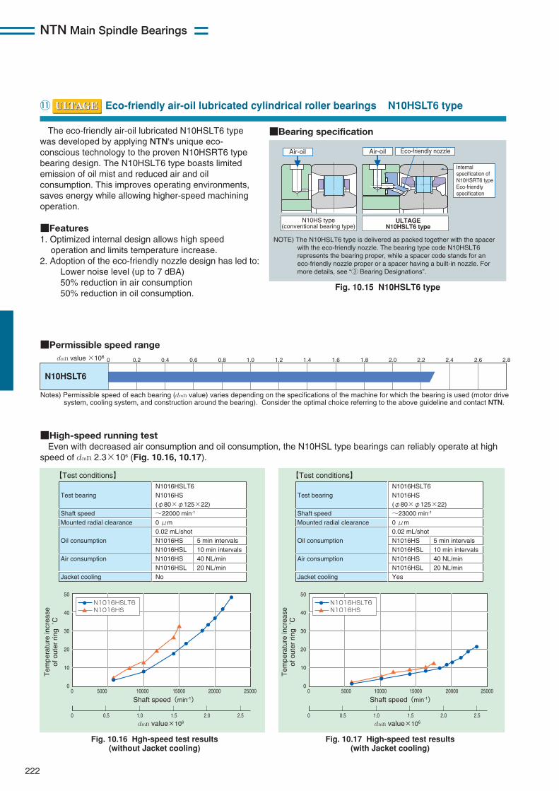
The eco-friendly air-oil lubricated N10HSLT6 typewas developed by applying NTN's unique eco-conscious technology to the proven N10HSRT6 typebearing design. The N10HSLT6 type boasts limitedemission of oil mist and reduced air and oilconsumption. This improves operating environments,saves energy while allowing higher-speed machiningoperation.
■Features1. Optimized internal design allows high speed
operation and limits temperature increase.2. Adoption of the eco-friendly nozzle design has led to:
Lower noise level (up to 7 dBA)50% reduction in air consumption50% reduction in oil consumption.
222
!1 Eco-friendly air-oil lubricated cylindrical roller bearings N10HSLT6 type
Fig. 10.15 N10HSLT6 type
■Permissible speed range
N10HSLT6
0 0.2 0.4 0.6 0.8 1.0 1.2 1.4 1.6 1.8 2.0 2.2 2.4 2.6 2.8
Notes) Permissible speed of each bearing (dmn value) varies depending on the specifications of the machine for which the bearing is used (motor drive system, cooling system, and construction around the bearing). Consider the optimal choice referring to the above guideline and contact NTN.
dmn value ×106
N10HS type (conventional bearing type)
Air-oil
ULTAGE N10HSLT6 type
Air-oil Eco-friendly nozzle
Internal specification of N10HSRT6 type Eco-friendly specification
NOTE) The N10HSLT6 type is delivered as packed together with the spacer with the eco-friendly nozzle. The bearing type code N10HSLT6 represents the bearing proper, while a spacer code stands for an eco-friendly nozzle proper or a spacer having a built-in nozzle. For more details, see “3 Bearing Designations”.
■Bearing specification
■High-speed running testEven with decreased air consumption and oil consumption, the N10HSL type bearings can reliably operate at high
speed of dmn 2.3×10⁶ (Fig. 10.16, 10.17).
Fig. 10.16 Hgh-speed test results (without Jacket cooling)
Fig. 10.17 High-speed test results (with Jacket cooling)
0 0.5 1.51.0 2.0 2.5
0 5000 15000 20000 2500010000
50
40
30
20
10
0
Shaft speed(min-1)
dmn value×106
Tem
pera
ture
incr
ease
of
out
er r
ing
˚C
Tem
pera
ture
incr
ease
of
out
er r
ing
˚C
Test bearing Shaft speed Mounted radial clearance Oil consumption Air consumption Jacket cooling
N1016HSLT6 N1016HS (φ80×φ125×22) ~22000 min-1 0 μm 0.02 mL/shotN1016HS N1016HSL N1016HS N1016HSL No
5 min intervals 10 min intervals 40 NL/min 20 NL/min
【Test conditions】
N1016HSN1016HSLT6
0 0.5 1.51.0 2.0 2.5
0 5000 15000 20000 2500010000
50
40
30
20
10
0
Shaft speed(min-1)
dmn value×106
Test bearing Shaft speed Mounted radial clearance Oil consumption Air consumption Jacket cooling
N1016HSLT6 N1016HS (φ80×φ125×22) ~23000 min-1 0 μm 0.02 mL/shotN1016HS N1016HSL N1016HS N1016HSL Yes
5 min intervals 10 min intervals 40 NL/min 20 NL/min
【Test conditions】
N1016HSN1016HSLT6

NTN Main Spindle Bearings
223

Main Spindle Bearings
224
!2 Dimension tables for double row cylindrical roller bearings
Double row cylindrical roller bearings
d 25〜95mm
— — NN3005 NN3005K 25 47 16 0.6 25.8 30.0 2 630 3 050 19 300 23 400— — NN3005HS NN3005HSK 25 47 16 0.6 25.8 30.0 2 630 3 050 22 600 31 100
— — NN3006 NN3006K 30 55 19 1 31.0 37.0 3 150 3 800 16 300 19 800— — NN3006HS NN3006HSK 30 55 19 1 31.0 37.0 3 150 3 800 19 100 26 300
— — NN3007 NN3007K 35 62 20 1 38.0 47.5 3 850 4 850 14 300 17 300— — NN3007HS NN3007HSK 35 62 20 1 38.0 47.5 3 850 4 850 16 700 23 100
— — NN3008 NN3008K 40 68 21 1 43.5 55.5 4 400 5 650 12 800 15 600— — NN3008HS NN3008HSK 40 68 21 1 43.5 55.5 4 400 5 650 15 000 20 700
— — NN3009 NN3009K 45 75 23 1 52.0 68.5 5 300 7 000 11 600 14 000— — NN3009HS NN3009HSK 45 75 23 1 52.0 68.5 5 300 7 000 13 600 18 700
— — NN3010 NN3010K 50 80 23 1 53.0 72.5 5 400 7 400 10 700 13 000— — NN3010HS NN3010HSK 50 80 23 1 53.0 72.5 5 400 7 400 12 500 17 300
— — NN3011 NN3011K 55 90 26 1.1 69.5 96.5 7 050 9 850 9 600 11 600— — NN3011HS NN3011HSK 55 90 26 1.1 69.5 96.5 7 050 9 850 11 200 15 500
— — NN3012 NN3012K 60 95 26 1.1 71.0 102 7 250 10 400 9 000 10 900— — NN3012HS NN3012HSK 60 95 26 1.1 71.0 102 7 250 10 400 10 500 14 500
— — NN3013 NN3013K 65 100 26 1.1 75.0 111 7 650 11 400 8 400 10 200— — NN3013HST6 NN3013HST6K 65 100 26 1.1 72.5 107 7 400 10 900 9 900 13 600— — NN3013HSRT6 NN3013HSRT6K 65 100 26 1.1 72.5 107 7 400 10 900 12 100 21 200
— — NN3014 NN3014K 70 110 30 1.1 94.5 143 9 650 14 600 7 700 9 300— — NN3014HST6 NN3014HST6K 70 110 30 1.1 92.0 137 9 350 14 000 9 000 12 400— — NN3014HSRT6 NN3014HSRT6K 70 110 30 1.1 92.0 137 9 350 14 000 11 000 19 300
— — NN3015 NN3015K 75 115 30 1.1 96.5 149 9 850 15 200 7 300 8 900— — NN3015HST6 NN3015HST6K 75 115 30 1.1 96.5 149 9 850 15 200 8 500 11 800— — NN3015HSRT6 NN3015HSRT6K 75 115 30 1.1 96.5 149 9 850 15 200 10 400 18 300
— — NN3016 NN3016K 80 125 34 1.1 116 179 11 800 18 200 6 800 8 300— — NN3016HST6 NN3016HST6K 80 125 34 1.1 112 172 11 500 17 500 8 000 11 000— — NN3016HSRT6 NN3016HSRT6K 80 125 34 1.1 112 172 11 500 17 500 9 700 17 100
— — NN3017 NN3017K 85 130 34 1.1 122 194 12 400 19 800 6 500 7 900— — NN3017HST6 NN3017HST6K 85 130 34 1.1 118 187 12 100 19 100 7 600 10 500— — NN3017HSRT6 NN3017HSRT6K 85 130 34 1.1 118 187 12 100 19 100 9 300 16 300
— — NN3018 NN3018K 90 140 37 1.5 143 228 14 600 23 200 6 000 7 300— — NN3018HST6 NN3018HST6K 90 140 37 1.5 143 228 14 600 23 200 7 100 9 700— — NN3018HSRT6 NN3018HSRT6K 90 140 37 1.5 143 228 14 600 23 200 8 600 15 200
— — NN3019 NN3019K 95 145 37 1.5 146 238 14 900 24 200 5 800 7 000
Part number Boundary Basic load ratings Limiting speedsdimensions dynamic static dynamic static
NNU Type NN Type mm kN kgf min-1
cylindrical tapered cylindrical tapered grease oilbore bore1 bore bore1 d D B rs min2 Cr Cor Cr Cor lubrication lubrication
1 A bearing number with suffix K indicates a tapered-bore bearing (taper ratio 1/12).2 Minimum allowable value for corner radius dimension r.A part number containing a suffix T6 means an ULTAGE Series.
r r r
r
Br
r
φdφd φEwφD
B
φd φd φFWφD
NNU Type Cylindrical bore Tapered bore
NN TypeCylindrical bore Tapered bore

225
Main Spindle Bearings
Dynamic equivalentradial loadPr=Fr
Static equivalentradial loadPor=Fr
− 41.3 29 30 − − − 43 42 0.6 − − 0.124 0.121 3.72− 41.3 29 30 − − − 43 42 0.6 − − 0.124 0.121 3.72
− 48.5 35 36.5 − − − 50 49 1 − − 0.199 0.193 6.38− 48.5 35 36.5 − − − 50 49 1 − − 0.199 0.193 6.38
− 55 40 41.5 − − − 57 56 1 − − 0.242 0.235 8.09− 55 40 41.5 − − − 57 56 1 − − 0.242 0.235 8.09
− 61 45 47 − − − 63 62 1 − − 0.312 0.303 9.68− 61 45 47 − − − 63 62 1 − − 0.312 0.303 9.68
− 67.5 50 52 − − − 70 69 1 − − 0.405 0.393 13.3− 67.5 50 52 − − − 70 69 1 − − 0.405 0.393 13.3
− 72.5 55 57 − − − 75 74 1 − − 0.433 0.419 14.6− 72.5 55 57 − − − 75 74 1 − − 0.433 0.419 14.6
− 81 61.5 63.5 − − − 83.5 82 1 − − 0.651 0.631 20.5− 81 61.5 63.5 − − − 83.5 82 1 − − 0.651 0.631 20.5
− 86.1 66.5 68.5 − − − 88.5 87 1 − − 0.704 0.683 21.1− 86.1 66.5 68.5 − − − 88.5 87 1 − − 0.704 0.683 21.1
— 91 71.5 73.5 — — — 93.5 92 1 — — 0.76 0.74 22.2— 91 71.5 73.5 — — — 93.5 92 1 — — 0.69 0.66 21.4— 91 71.5 73.5 — — — 93.5 92 1 — — 0.69 0.66 21.4
— 100 76.5 79 — — — 103.5 101 1 — — 1.04 1.01 33.0— 100 76.5 79 — — — 103.5 101 1 — — 0.99 0.96 30.4— 100 76.5 79 — — — 103.5 101 1 — — 0.99 0.96 30.4
— 105 81.5 84 — — — 108.5 106 1 — — 1.14 1.11 35.0— 105 81.5 84 — — — 108.5 106 1 — — 1.05 1.02 31.2— 105 81.5 84 — — — 108.5 106 1 — — 1.05 1.02 31.2
— 113 86.5 89.5 — — — 118.5 114 1 — — 1.52 1.47 45.0— 113 86.5 89.5 — — — 118.5 114 1 — — 1.43 1.38 43.0— 113 86.5 89.5 — — — 118.5 114 1 — — 1.43 1.38 43.0
— 118 91.5 84.5 — — — 123.5 119 1 — — 1.61 1.56 48.8— 118 91.5 84.5 — — — 123.5 119 1 — — 1.51 1.46 44.4— 118 91.5 84.5 — — — 123.5 119 1 — — 1.51 1.46 44.4
— 127 98 101 — — — 132 129 1.5 — — 2.07 2.01 64.1— 127 98 101 — — — 132 129 1.5 — — 1.97 1.91 57.6— 127 98 101 — — — 132 129 1.5 — — 1.97 1.91 57.6
— 132 103 106 — — — 137 134 1.5 — — 2.17 2.10 67.0
Dimensions Abutment and fillet dimensions Mass Internalkg (approx.) free space
mm mm NNU Type NN Type cm3
da db dc dd Da Db ras cylindrical tapered cylindrical tapered NNFw Ew min min max min max max min max bore bore bore bore Type
ra
ra ra
ra
ra
φdbφdaφDb φDb φdaφDbφdaφdc φddφDa

Main Spindle Bearings
226
NNU4920 NNU4920K NN4920 NN4920K 100 140 40 1.1 131 260 13 300 26 500 6 000 7 200— — NN3020 NN3020K 100 150 37 1.5 153 256 15 600 26 100 5 600 6 700— — NN3020HST6 NN3020HST6K 100 150 37 1.5 149 247 15 200 25 200 6 500 9 000— — NN3020HSRT6 NN3020HSRT6K 100 150 37 1.5 149 247 15 200 25 200 8 000 14 000
NNU4921 NNU4921K NN4921 NN4921K 105 145 40 1.1 133 268 13 500 27 400 5 700 6 900— — NN3021 NN3021K 105 160 41 2 198 320 20 200 33 000 5 300 6 400— — NN3021HST6 NN3021HST6K 105 160 41 2 198 320 20 200 33 000 6 200 8 500— — NN3021HSRT6 NN3021HSRT6K 105 160 41 2 198 320 20 200 33 000 7 100 11 300
NNU4922 NNU4922K NN4922 NN4922K 110 150 40 1.1 137 284 14 000 28 900 5 500 6 600— — NN3022 NN3022K 110 170 45 2 229 375 23 300 38 000 5 000 6 000— — NN3022HST6 NN3022HST6K 110 170 45 2 229 375 23 300 38 000 5 800 8 000— — NN3022HSRT6 NN3022HSRT6K 110 170 45 2 229 375 23 300 38 000 6 700 10 600
NNU4924 NNU4924K NN4924 NN4924K 120 165 45 1.1 183 360 18 700 37 000 5 000 6 000— — NN3024 NN3024K 120 180 46 2 233 390 23 700 40 000 4 600 5 600— — NN3024HST6 NN3024HST6K 120 180 46 2 226 380 23 100 38 500 5 400 7 500— — NN3024HSRT6 NN3024HSRT6K 120 180 46 2 226 380 23 100 38 500 6 200 9 900
NNU4926 NNU4926K NN4926 NN4926K 130 180 50 1.5 220 440 22 400 45 000 4 600 5 500— — NN3026 NN3026K 130 200 52 2 284 475 29 000 48 500 4 200 5 100— — NN3026HST6 NN3026HST6K 130 200 52 2 284 475 29 000 48 500 4 900 6 800— — NN3026HSRT6 NN3026HSRT6K 130 200 52 2 284 475 29 000 48 500 5 700 9 000
NNU4928 NNU4928K NN4928 NN4928K 140 190 50 1.5 227 470 23 100 48 000 4 300 5 200— — NN3028 NN3028K 140 210 53 2 298 515 30 500 52 500 4 000 4 800
— — NN3028HST6 NN3028HST6K 140 210 53 2 298 515 30 500 52 500 4 700 6 400
NNU4930 NNU4930K NN4930 NN4930K 150 210 60 2 345 690 35 000 70 500 3 900 4 800— — NN3030 NN3030K 150 225 56 2.1 335 585 34 000 60 000 3 700 4 500— — NN3030HS NN3030HSK 150 225 56 2.1 335 585 34 000 60 000 4 300 6 000
NNU4932 NNU4932K NN4932 NN4932K 160 220 60 2 355 740 36 500 75 500 3 700 4 500— — NN3032 NN3032K 160 240 60 2.1 375 660 38 000 67 500 3 500 4 200— — NN3032HS NN3032HSK 160 240 60 2.1 375 660 38 000 67 500 4 100 5 600
NNU4934 NNU4934K NN4934 NN4934K 170 230 60 2 360 765 37 000 78 000 3 600 4 300— — NN3034 NN3034K 170 260 67 2.1 440 775 45 000 79 000 3 200 3 900
NNU4936 NNU4936K NN4936 NN4936K 180 250 69 2 460 965 46 500 98 500 3 200 3 800— — NN3036 NN3036K 180 280 74 2.1 565 995 57 500 102 000 3 000 3 600
NNU4938 NNU4938K NN4938 NN4938K 190 260 69 2 475 1 030 48 500 105 000 3 000 3 600— — NN3038 NN3038K 190 290 75 2.1 580 1 040 59 000 106 000 2 800 3 300
Part number Boundary Basic load ratings Limiting speedsdimensions dynamic static dynamic static
NNU Type NN Type mm kN kgf min-1
cylindrical tapered cylindrical tapered grease oilbore bore1 bore bore1 d D B rs min2 Cr Cor Cr Cor lubrication lubrication
1 A bearing number with suffix K indicates a tapered-bore bearing (taper ratio 1/12).2 Minimum allowable value for corner radius dimension r.A part number containing a suffix T6 means an ULTAGE Series
Double row cylindrical roller bearings
d 100〜190mmr r r
r
Br
r
φdφd φEwφD
B
φd φd φFWφD
NNU Type Cylindrical bore Tapered bore
NN TypeCylindrical bore Tapered bore

227
Main Spindle Bearings
Dynamic equivalentradial loadPr=Fr
Static equivalentradial loadPor=Fr
113 129 106.5 110 111 115 133.5 133.5 131 1 1.83 1.75 1.75 1.67 49.8— 137 108 111 — — — 142 139 1.5 — — 2.26 2.19 67.5— 137 108 111 — — — 142 139 1.5 — — 2.14 2.07 61.6— 137 108 111 — — — 142 139 1.5 — — 2.14 2.07 61.6
118 134 111.5 115 116 120 138.5 138.5 136 1 1.91 1.82 1.82 1.73 50.2— 146 114 117 — — — 151 148 2 — — 2.89 2.80 91.9— 146 114 117 — — — 151 148 2 — — 2.75 2.66 82.7— 146 114 117 — — — 151 148 2 — — 2.75 2.66 82.7
123 139 116.5 120 121 125 143.5 143.5 141 1 1.99 1.90 1.90 1.81 53.9— 155 119 123 — — — 161 157 2 — — 3.69 3.56 115— 155 119 123 — — — 161 157 2 — — 3.50 3.37 103— 155 119 123 — — — 161 157 2 — — 3.50 3.37 103
134.5 154.5 126.5 130 133 137 158.5 158.5 156.5 1 2.75 2.62 2.63 2.51 82.5— 165 129 133 — — — 171 167 2 — — 3.98 3.83 130— 165 129 133 — — — 171 167 2 — — 3.76 3.61 117— 165 129 133 — — — 171 167 2 — — 3.76 3.61 117
146 168 138 142 144 148 172 172 170 1.5 3.69 3.52 3.52 3.35 112— 182 139 143 — — — 191 183 2 — — 5.92 5.71 182— 182 139 143 — — — 191 183 2 — — 5.55 5.34 164— 182 139 143 — — — 191 183 2 — — 5.55 5.34 164
156 178 148 152 154 158 182 182 180 1.5 3.94 3.76 3.76 3.58 117− 192 149 153 − − − 201 194 2 − − 6.44 6.21 199− 192 149 153 − − − 201 194 2 − − 6.11 5.91 176
168.5 196.5 159 164 166 171 201 201 198.5 2 6.18 5.90 5.90 5.62 192− 206 161 166 − − − 214 208 2 − − 7.81 7.53 237− 206 161 166 − − − 214 208 2 − − 7.81 7.53 237
178.5 206.5 169 174 176 182 211 211 208.5 2 6.53 6.23 6.24 5.94 199− 219 171 176 − − − 229 221 2 − − 8.92 8.59 287− 219 171 176 − − − 229 221 2 − − 8.92 8.59 287
188.5 216.5 179 184 186 192 221 221 218.5 2 6.87 6.55 6.56 6.24 212− 236 181 187 − − − 249 238 2 − − 12.6 12.2 379
202 234 189 195 199 205 241 241 236 2 9.90 9.46 9.45 9.01 299− 255 191 197 − − − 269 257 2 − − 16.6 16.0 478
212 244 199 205 209 215 251 251 246 2 10.4 9.94 9.93 9.47 303− 265 201 207 − − − 279 267 2 − − 18.0 17.4 504
Dimensions Abutment and fillet dimensions Mass Internalkg (approx.) free space
mm mm NNU Type NN Type cm3
da db dc dd Da Db ras cylindrical tapered cylindrical tapered NNFw Ew min min max min max max min max bore bore bore bore Type
ra
ra ra
ra
ra
φdbφdaφDb φDb φdaφDbφdaφdc φddφDa

Main Spindle Bearings
228
Part number Boundary Basic load ratings Limiting speedsdimensions dynamic static dynamic static
NNU Type NN Type mm kN kgf min-1
cylindrical tapered cylindrical tapered grease oilbore bore1 bore bore1 d D B rs min2 Cr Cor Cr Cor lubrication lubrication
1 A bearing number with suffix K indicates a tapered-bore bearing (taper ratio 1/12).2 Minimum allowable value for corner radius dimension r.
r r r
r
Br
r
φdφd φEwφD
B
φd φd φFWφD
NNU Type Cylindrical bore Tapered bore
NN TypeCylindrical bore Tapered bore
NNU4940 NNU4940K NN4940 NN4940K 200 280 80 2.1 555 1 180 56 500 120 000 2 900 3 500— — NN3040 NN3040K 200 310 82 2.1 655 1 170 66 500 119 000 2 600 3 100
NNU4944 NNU4944K NN4944 NN4944K 220 300 80 2.1 585 1 300 59 500 132 000 2 600 3 100— — NN3044 NN3044K 220 340 90 3 815 1 480 83 000 151 000 2 300 2 800
NNU4948 NNU4948K NN4948 NN4948K 240 320 80 2.1 610 1 410 62 500 144 000 2 300 2 800— — NN3048 NN3048K 240 360 92 3 855 1 600 87 000 163 000 2 200 2 600
NNU4952 NNU4952K NN4952 NN4952K 260 360 100 2.1 900 2 070 92 000 211 000 2 200 2 600— — NN3052 NN3052K 260 400 104 4 1 060 1 990 108 000 203 000 2 100 2 500
NNU4956 NNU4956K NN4956 NN4956K 280 380 100 2.1 925 2 200 94 500 224 000 1 900 2 300— — NN3056 NN3056K 280 420 106 4 1 080 2 080 110 000 212 000 1 800 2 100
NNU4960 NNU4960K NN4960 NN4960K 300 420 118 3 1 200 2 800 122 000 285 000 1 800 2 100— — NN3060 NN3060K 300 460 118 4 1 330 2 560 135 000 261 000 1 600 2 000
NNU4964 NNU4964K NN4964 NN4964K 320 440 118 3 1 240 2 970 126 000 305 000 1 600 2 000— — NN3064 NN3064K 320 480 121 4 1 350 2 670 138 000 272 000 1 500 1 800
NNU4968 NNU4968K — — 340 460 118 3 1 270 3 150 130 000 320 000 1 500 1 800— — NN3068 NN3068K 340 520 133 5 1 620 3 200 165 000 325 000 1 500 1 800
NNU4972 NNU4972K — — 360 480 118 3 1 290 3 250 131 000 330 000 1 500 1 800— — NN3072 NN3072K 360 540 134 5 1 650 3 300 169 000 340 000 1 400 1 600
NNU4976 NNU4976K — — 380 520 140 4 1 630 4 050 167 000 415 000 1 400 1 600— — NN3076 NN3076K 380 560 135 5 1 690 3 450 172 000 355 000 1 300 1 500
NNU4980 NNU4980K — — 400 540 140 4 1 690 4 300 172 000 435 000 1 300 1 500— — NN3080 NN3080K 400 600 148 5 2 040 4 150 208 000 420 000 1 200 1 400
NNU4984 NNU4984K — — 420 560 140 4 1 740 4 500 177 000 460 000 1 200 1 500— — NN3084 NN3084K 420 620 150 5 2 080 4 300 212 000 440 000 1 100 1 400
NNU4988 NNU4988K — — 440 600 160 4 2 150 5 550 219 000 565 000 1 100 1 400— — NN3088 NN3088K 440 650 157 6 2 420 5 100 247 000 520 000 1 100 1 300
NNU4992 NNU4992K — — 460 620 160 4 2 220 5 850 226 000 595 000 1 100 1 300— — NN3092 NN3092K 460 680 163 6 2 550 5 350 260 000 545 000 1 000 1 200
NNU4996 NNU4996K — — 480 650 170 5 2 280 5 900 233 000 600 000 1 000 1 200
NNU49/500 NNU49/500K — — 500 670 170 5 2 360 6 200 240 000 635 000 1 000 1 200
Double row cylindrical roller bearings
d 200〜500mm

229
Main Spindle Bearings
Dynamic equivalentradial loadPr=Fr
Static equivalentradial loadPor=Fr
Dimensions Abutment and fillet dimensions Mass Internalkg (approx.) free space
mm mm NNU Type NN Type cm3
da db dc dd Da Db ras cylindrical tapered cylindrical tapered NNFw Ew min min max min max max min max bore bore bore bore Type
ra
ra ra
ra
ra
φdbφdaφDb φDb φdaφDbφdaφdc φddφDa
225 261 211 218 222 228 269 269 264 2 14.7 14.0 14.0 13.3 437− 282 211 218 − − − 299 285 2 − − 21.6 20.8 649
245 281 231 238 242 248 289 289 284 2 15.9 15.2 15.2 14.5 485− 310 233 240 − − − 327 313 2.5 − − 29.3 28.2 877
265 301 251 258 262 269 309 309 304 2 17.2 16.4 16.4 15.6 518− 330 253 261 − − − 347 333 2.5 − − 32.8 31.6 973
292 336 271 279 288 296 349 349 339 2 29.6 28.3 28.3 27.0 850− 364 276 285 − − − 384 367 3 − − 47.4 45.8 1 370
312 356 291 299 308 316 369 369 359 2 31.6 30.2 30.2 28.8 897− 384 296 305 − − − 404 387 3 − − 51.1 49.3 1 500
339 391 313 323 335 343 407 407 394 2.5 48.6 46.4 46.4 44.2 1 360− 418 316 326 − − − 444 421 3 − − 70.8 68.6 2 000
359 411 333 343 355 363 427 427 414 2.5 51.4 49.1 49.0 46.7 1 450− 438 336 346 − − − 464 441 3 − − 76.2 73.5 2 200
379 − 353 363 375 383 447 − − 2.5 54.2 51.7 − − −− 473 360 371 − − − 500 477 4 − − 102 98.5 2 950
398 − 373 383 394 402 467 − − 2.5 57.0 54.4 − − −− 493 380 391 − − − 520 497 4 − − 107 103 3 600
425 − 396 408 420 430 504 − − 3 84.5 80.6 − − −− 512 400 411 − − − 540 516 4 − − 113 109 3 340
445 − 416 428 440 450 524 − − 3 88.2 84.1 − − −− 547 420 432 − − − 580 551 4 − − 146 141 4 230
465 − 436 448 460 470 544 − − 3 92.0 87.7 − − −− 567 440 452 − − − 600 571 4 − − 154 148 4 520
492 − 456 469 487 497 584 − − 3 127 121 − − −− 596 464 477 − − − 626 601 5 − − 178 172 5 000
512 − 476 489 507 517 604 − − 3 132 126 − − −− 622 484 498 − − − 656 627 5 − − 202 195 6 030
534 − 500 514 531 541 630 − − 4 156 149 − − −
556 − 520 534 551 561 650 − − 4 162 155 − − −
Main Spindle Bearings
230
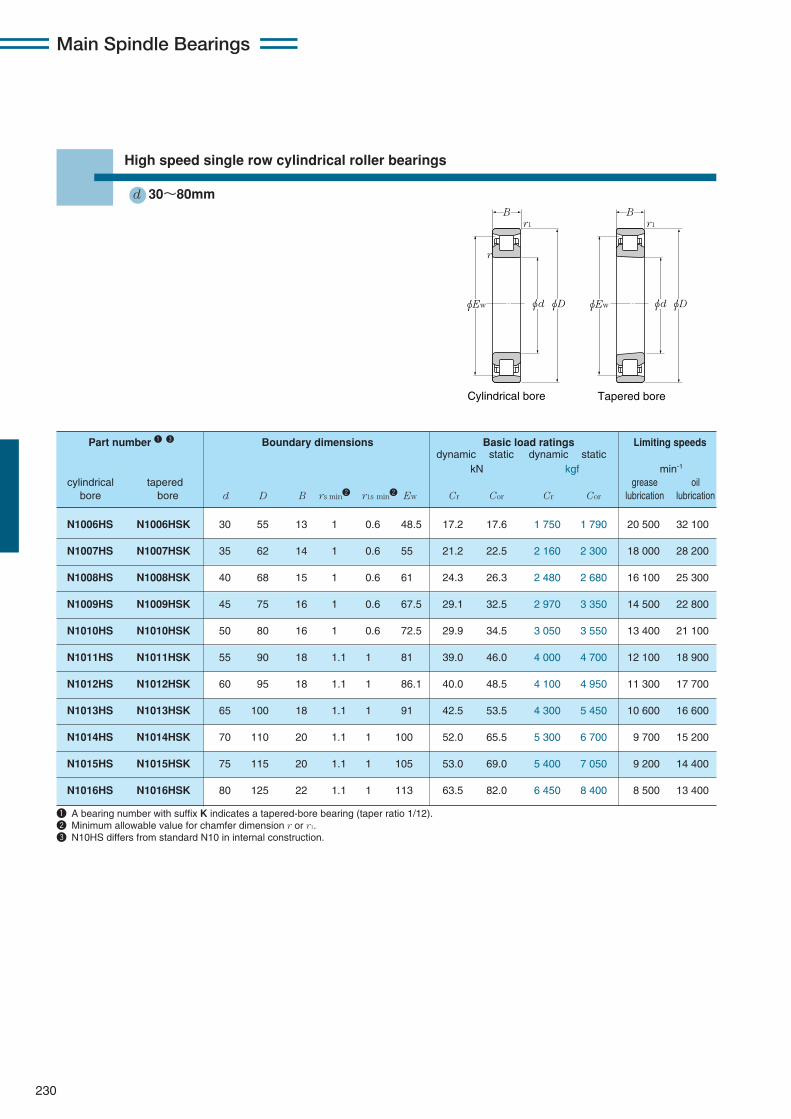
High speed single row cylindrical roller bearings
d 30〜80mm
Tapered boreCylindrical bore
r
r1 r1
B B
φEw φEwφd φdφD φD
N1006HS N1006HSK 30 55 13 1 0.6 48.5 17.2 17.6 1 750 1 790 20 500 32 100
N1007HS N1007HSK 35 62 14 1 0.6 55 21.2 22.5 2 160 2 300 18 000 28 200
N1008HS N1008HSK 40 68 15 1 0.6 61 24.3 26.3 2 480 2 680 16 100 25 300
N1009HS N1009HSK 45 75 16 1 0.6 67.5 29.1 32.5 2 970 3 350 14 500 22 800
N1010HS N1010HSK 50 80 16 1 0.6 72.5 29.9 34.5 3 050 3 550 13 400 21 100
N1011HS N1011HSK 55 90 18 1.1 1 81 39.0 46.0 4 000 4 700 12 100 18 900
N1012HS N1012HSK 60 95 18 1.1 1 86.1 40.0 48.5 4 100 4 950 11 300 17 700
N1013HS N1013HSK 65 100 18 1.1 1 91 42.5 53.5 4 300 5 450 10 600 16 600
N1014HS N1014HSK 70 110 20 1.1 1 100 52.0 65.5 5 300 6 700 9 700 15 200
N1015HS N1015HSK 75 115 20 1.1 1 105 53.0 69.0 5 400 7 050 9 200 14 400
N1016HS N1016HSK 80 125 22 1.1 1 113 63.5 82.0 6 450 8 400 8 500 13 400
Part number 1 3 Boundary dimensions Basic load ratings Limiting speedsdynamic static dynamic static
kN kgf min-1
cylindrical tapered grease oilbore bore d D B rs min2 r1s min2 Ew Cr Cor Cr Cor lubrication lubrication
1 A bearing number with suffix K indicates a tapered-bore bearing (taper ratio 1/12).2 Minimum allowable value for chamfer dimension r or r1.3 N10HS differs from standard N10 in internal construction.

231
Main Spindle Bearings
Dynamic equivalentradial loadPr=Fr
Static equivalentradial loadPor=Fr
35 50 49 1 0.6 0.143 4.33 N1006HS N1006HSK
40 57 56 1 0.6 0.190 5.06 N1007HS N1007HSK
45 63 62 1 0.6 0.235 7.10 N1008HS N1008HSK
50 70 69 1 0.6 0.298 8.85 N1009HS N1009HSK
55 75 74 1 0.6 0.323 10.8 N1010HS N1010HSK
61.5 83.5 82 1 1 0.473 15.0 N1011HS N1011HSK
66.5 88.5 87 1 1 0.505 15.3 N1012HS N1012HSK
71.5 93.5 92 1 1 0.538 19.0 N1013HS N1013HSK
76.5 103.5 101 1 1 0.745 22.0 N1014HS N1014HSK
81.5 108.5 106 1 1 0.787 26.5 N1015HS N1015HSK
86.5 118.5 114 1 1 1.05 31.1 N1016HS N1016HSK
Abutment and Mass Internal Part number fillet dimensions cylindrical free space
mm bore cm3
da Db ras r1as kg cylindrical taperedmin max min max max (approx.) bore bore
φDb φdaφDb
r1a
ra

Main Spindle Bearings
232
High speed single row cylindrical roller bearings
d 85〜160mm
1 A bearing number with suffix K indicates a tapered-bore bearing (taper ratio 1/12).2 Minimum allowable value for chamfer dimension r or r1.3 N10HS differs from standard N10 in internal construction.
Tapered boreCylindrical bore
r
r1 r1
B B
φEw φEwφd φdφD φD
N1017HS N1017HSK 85 130 22 1.1 1 118 65.0 86.0 6 650 8 800 8 100 12 800
N1018HS N1018HSK 90 140 24 1.5 1.1 127 78.5 105 8 000 10 700 7 600 11 900
N1019HS N1019HSK 95 145 24 1.5 1.1 132 80.5 110 8 200 11 200 7 300 11 400
N1020HS N1020HSK 100 150 24 1.5 1.1 137 82.0 115 8 400 11 700 7 000 11 000
N1021HS N1021HSK 105 160 26 2 1.1 146 109 149 11 100 15 200 6 600 10 400
N1022HS N1022HSK 110 170 28 2 1.1 155 126 173 12 800 17 700 6 200 9 800
N1024HS N1024HSK 120 180 28 2 1.1 165 128 182 13 100 18 500 5 800 9 100
N1026HS N1026HSK 130 200 33 2 1.1 182 156 220 15 900 22 400 5 300 8 300
N1028HS N1028HSK 140 210 33 2 1.1 192 164 240 16 800 24 400 5 000 7 800
N1030HS N1030HSK 150 225 35 2.1 1.5 206 185 273 18 800 27 800 4 700 7 300
N1032HS N1032HSK 160 240 38 2.1 1.5 219 206 305 21 000 31 500 4 400 6 900
Part number 1 3 Boundary dimensions Basic load ratings Limiting speedsdynamic static dynamic static
kN kgf min-1
cylindrical tapered grease oilbore bore d D B rs min2 r1s min2 Ew Cr Cor Cr Cor lubrication lubrication

233
Main Spindle Bearings
Dynamic equivalentradial loadPr=Fr
Static equivalentradial loadPor=Fr
φDb φdaφDb
r1a
ra
91.5 123.5 119 1 1 1.10 33.4 N1017HS N1017HSK
98 132 129 1.5 1 1.43 40.0 N1018HS N1018HSK
103 137 134 1.5 1 1.50 46.5 N1019HS N1019HSK
108 142 139 1.5 1 1.55 53.5 N1020HS N1020HSK
114 151 148 2 1 1.96 56.2 N1021HS N1021HSK
119 161 157 2 1 2.44 68.8 N1022HS N1022HSK
129 171 167 2 1 2.61 87.5 N1024HS N1024HSK
139 191 183 2 1 3.95 118 N1026HS N1026HSK
149 201 194 2 1 4.19 130 N1028HS N1028HSK
161 214 208 2 1.5 5.10 151 N1030HS N1030HSK
171 229 221 2 1.5 6.30 172 N1032HS N1032HSK
Abutment and Mass Internal Part number fillet dimensions cylindrical free space
mm bore cm3
da Db ras r1as kg cylindrical taperedmin max min max max (approx.) bore bore
Main Spindle Bearings
234
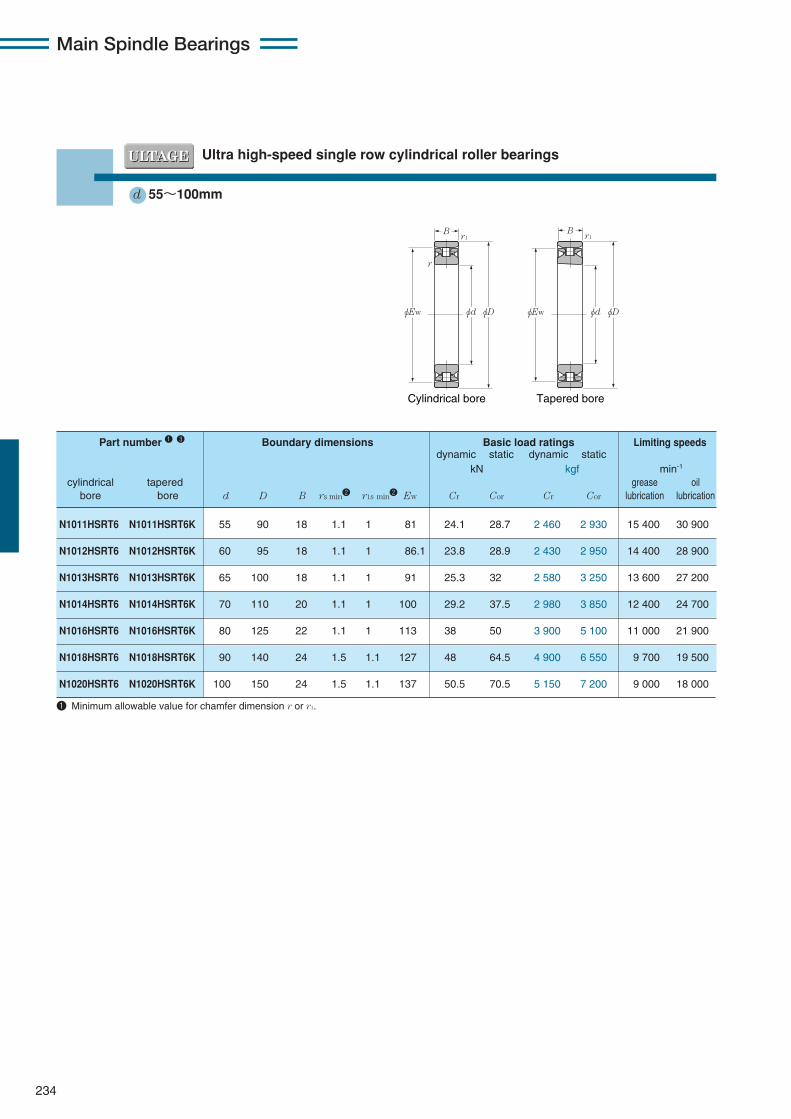
Ultra high-speed single row cylindrical roller bearings
d 55〜100mm
Tapered boreCylindrical bore
r1
φEw φd φD
Br1
r
φEw φd φD
B
1 Minimum allowable value for chamfer dimension r or r1.
N1011HSRT6 N1011HSRT6K 55 90 18 1.1 1 81 24.1 28.7 2 460 2 930 15 400 30 900
N1012HSRT6 N1012HSRT6K 60 95 18 1.1 1 86.1 23.8 28.9 2 430 2 950 14 400 28 900
N1013HSRT6 N1013HSRT6K 65 100 18 1.1 1 91 25.3 32 2 580 3 250 13 600 27 200
N1014HSRT6 N1014HSRT6K 70 110 20 1.1 1 100 29.2 37.5 2 980 3 850 12 400 24 700
N1016HSRT6 N1016HSRT6K 80 125 22 1.1 1 113 38 50 3 900 5 100 11 000 21 900
N1018HSRT6 N1018HSRT6K 90 140 24 1.5 1.1 127 48 64.5 4 900 6 550 9 700 19 500
N1020HSRT6 N1020HSRT6K 100 150 24 1.5 1.1 137 50.5 70.5 5 150 7 200 9 000 18 000
Part number 1 3 Boundary dimensions Basic load ratings Limiting speedsdynamic static dynamic static
kN kgf min-1
cylindrical tapered grease oilbore bore d D B rs min2 r1s min2 Ew Cr Cor Cr Cor lubrication lubrication

235
Main Spindle Bearings
Dynamic equivalentradial loadPr=Fr
Static equivalentradial loadPor=Fr
61.5 83.5 82 1 1 15.7 N1011HSRT6 N1011HSRT6K
66.5 88.5 87 1 1 17.0 N1012HSRT6 N1012HSRT6K
71.5 93.5 92 1 1 17.9 N1013HSRT6 N1013HSRT6K
76.5 103.5 101 1 1 23.3 N1014HSRT6 N1014HSRT6K
86.5 118.5 114 1 1 31.6 N1016HSRT6 N1016HSRT6K
98 132 129 1.5 1 41.1 N1018HSRT6 N1018HSRT6K
108 142 139 1.5 1 45.1 N1020HSRT6 N1020HSRT6K
Abutment and Internal Part number fillet dimensions free space
mm cm3
da Db ras r1as cylindrical taperedmin max min max max bore bore
ra
r1a
φDbφda

Main Spindle Bearings
236
Eco-friendly ultra high-speed single row cylindrical roller bearingsAir-oil lubrication only
d 55〜100mm
Tapered boreCylindrical bore
r1
φEw φd φD
B
r
r1
φEw φd φD
B
1 Minimum allowable value for chamfer dimension r or r1.2 For the details of spacer dimensions, please contact NTN Engineering.
N1011HSLT6 N1011HSLT6K 55 90 18 1.1 1 81 24.1 28.7 2 460 2 930 30 900
N1012HSLT6 N1012HSLT6K 60 95 18 1.1 1 86.1 23.8 28.9 2 430 2 950 28 900
N1013HSLT6 N1013HSLT6K 65 100 18 1.1 1 91 25.3 32 2 580 3 250 27 200
N1014HSLT6 N1014HSLT6K 70 110 20 1.1 1 100 29.2 37.5 2 980 3 850 24 700
N1016HSLT6 N1016HSLT6K 80 125 22 1.1 1 113 38 50 3 900 5 100 21 900
N1018HSLT6 N1018HSLT6K 90 140 24 1.5 1.1 127 48 64.5 4 900 6 550 19 500
N1020HSLT6 N1020HSLT6K 100 150 24 1.5 1.1 137 50.5 70.5 5 150 7 200 18 000
Part number Boundary dimensions Basic load ratings Limiting speedsdynamic static dynamic static
kN kgf min-1
cylindrical tapered greasebore bore d D B rs min1 r1s min1 Ew Cr Cor Cr Cor lubrication

237
Main Spindle Bearings
Dynamic equivalentradial loadPr=Fr
Static equivalentradial loadPor=Fr
61.5 83.5 82 1 1 8.5 N1011HSLT6 N1011HSLT6K
66.5 88.5 87 1 1 8.5 N1012HSLT6 N1012HSLT6K
71.5 93.5 92 1 1 8.5 N1013HSLT6 N1013HSLT6K
76.5 103.5 101 1 1 10 N1014HSLT6 N1014HSLT6K
86.5 118.5 114 1 1 10 N1016HSLT6 N1016HSLT6K
98 132 129 1.5 1 10 N1018HSLT6 N1018HSLT6K
108 142 139 1.5 1 10 N1020HSLT6 N1020HSLT6K
Abutment and Part number fillet dimensions
mm
da Db ras r1as r2 cylindrical taperedmin max min max max min bore bore
ra
r1a
φDbφda
r

Main Spindle Bearings
238
!3 Taper gage and internal clearance adjustment gage for NTN precision cylindrical roller bearings
!4 Dimension table for taper gage
TANN3006K TBNN3006K N1006HS NN3006K 30 31.583 70 19 0.5 0.2TANN3007K TBNN3007K N1007HS NN3007K 35 36.667 75 20 0.6 0.3TANN3008K TBNN3008K N1008HS NN3008K 40 41.750 80 21 0.7 0.3
TANN3009K TBNN3009K N1009HS NN3009K 45 46.917 85 23 0.7 0.4TANN3010K TBNN3010K N1010HS NN3010K 50 51.917 90 23 0.8 0.5TANN3011K TBNN3011K N1011HS NN3011K 55 57.167 95 26 0.9 0.7
TANN3012K TBNN3012K N1012HS NN3012K 60 62.167 100 26 1.0 0.8TANN3013K TBNN3013K N1013HS NN3013K 65 67.167 105 26 1.1 0.9TANN3014K TBNN3014K N1014HS NN3014K 70 72.500 110 30 1.3 1.3
TANN3015K TBNN3015K N1015HS NN3015K 75 77.500 115 30 1.4 1.4TANN3016K TBNN3016K N1016HS NN3016K 80 82.833 125 34 1.9 1.7TANN3017K TBNN3017K N1017HS NN3017K 85 87.833 130 34 2.0 1.9
TANN3018K TBNN3018K N1018HS NN3018K 90 93.083 140 37 2.6 2.4TANN3019K TBNN3019K N1019HS NN3019K 95 98.083 145 37 2.7 2.6TANN3020K TBNN3020K N1020HS NN3020K 100 103.083 150 37 2.8 2.8
TANN3021K TBNN3021K N1021HS NN3021K 105 108.417 160 41 3.6 3.5TANN3022K TBNN3022K N1022HS NN3022K 110 113.750 165 45 4.1 4.0TANN3024K TBNN3024K N1024HS NN3024K 120 123.833 170 46 4.1 4.7
TANN3026K TBNN3026K N1026HS NN3026K 130 134.333 180 52 4.8 6.4TANN3028K TBNN3028K N1028HS NN3028K 140 144.417 190 53 5.2 7.4TANN3030K TBNN3030K N1030HS NN3030K 150 154.667 210 56 7.2 8.4TANN3032K TBNN3032K N1032HS NN3032K 160 165.000 220 60 8.1 10
Part number Applicable bearing Boundary dimensions Mass(approx.)
mm kgtype type
Plug gage Ring gage d d1 D B TB TA
φd
φdφD
φd1
φd1
B
B
Ring gage (TB)
Taper 1/12
Plug gage (TA)
Taper 1/12
As the need increases for machine tools of higherspeed and precision, a higher degree of precision isrequired of machine tool bearings. For a precisionbearing to exhibit its full performance, it must beinstalled correctly. In particular, when a tapered borebearing is used, the corresponding taper on the shaftmust be finished to a high degree of precision. NTNrecommends the ring gage for the tapered shaft befinished to the same precision as for bearings. Note thatthe contact area between tapered faces should be 80%or greater.
NTN also offers a plug gage that permits verification ofthe precision of the ring gage. Remember that the radialinternal clearance of a cylindrical roller bearing needs tobe correctly adjusted. Too large a radial clearance candiminish the precision of the main spindle, while toosmall a radial clearance can lead to abnormal heatgeneration and premature flaking of the bearing. Toensure adequate internal clearance, use a mountedinternal clearance adjustment gage.

239
Main Spindle Bearings
!5 Dimension table for mounted internal clearance adjustment gage
SBNN3007-2 N1007HSK NN3007K 55 101 23SBNN3008-2 N1008HSK NN3008K 61 107 23SBNN3009-2 N1009HSK NN3009K 67.5 114 23
SBNN3010-2 N1010HSK NN3010K 72.5 120 23SBNN3011-2 N1011HSK NN3011K 81 131 25SBNN3012-2 N1012HSK NN3012K 86.1 138 25
SBNN3013-2 N1013HSK NN3013K 91 145 25SBNN3014-2 N1014HSK NN3014K 100 156 28SBNN3015-2 N1015HSK NN3015K 105 161 28
SBNN3016-2 N1016HSK NN3016K 113 175 30SBNN3017-2 N1017HSK NN3017K 118 185 30SBNN3018-2 N1018HSK NN3018K 127 195 33
SBNN3019-2 N1019HSK NN3019K 132 204 33SBNN3020-2 N1020HSK NN3020K 137 210 33SBNN3021-2 N1021HSK NN3021K 146 220 36
SBNN3022-2 N1022HSK NN3022K 155 235 40SBNN3024-2 N1024HSK NN3024K 165 250 40SBNN3026-2 N1026HSK NN3026K 182 275 45
SBNN3028-2 N1028HSK NN3028K 192 285 45SBNN3030-2 N1030HSK NN3030K 206 305 50SBNN3032-2 N1032HSK NN3032K 219 320 50
Part Applicable bearing Boundarynumber dimensions
mm
E D width B