maine stormwater anagement design anual i… · maine stormwater management manual volume iii –...
TRANSCRIPT

MAINE STORMWATER MANAGEMENT MANUAL – January 2016
MAINE DEPARTMENT OF ENVIRONMENTAL PROTECTION17 State House Station | Augusta, Maine 04333-0017
www.maine.gov/dep
MAINE STORMWATER
MANAGEMENT DESIGN MANUAL
Technical Design Manual Volume III
MAY 2016

MAINE STORMWATER MANAGEMENT MANUAL
VOLUME III – Technical Design Manual Chapter 1 Introduction Chapter 2 Stormwater Hydrology Chapter 3 Detention Basins for Flooding Control Chapter 4 Wetponds Chapter 5 Vegetated Buffers Chapter 6 Infiltration BMPs Chapter 7 Filtration BMPs 7.1 Grassed Underdrained Soil Filters 7.2 Bioretention Filters 7.3 Subsurface Sand Filters 7.4 Gravel Wetlands 7.5 Roof Dripline Filters 7.6 Vegetated Roofs 7.7 Manmade Pervious Surfaces Chapter 8 Conveyance and Distribution Systems Chapter 9 Separator BMPs Chapter 10 LID Practices and Techniques Chapter 11 Operation and Maintenance Appendix A Runoff Estimation and Hydrologic Models Appendix B Approval Letters for Proprietary Systems

ACKNOWLEDGMENTS
This manual was produced by the Maine Department of Environmental Protection (DEP). This May 2016 edition supersedes these manuals:
Stormwater Management for Maine: Best Management Practices, November 1995, and Stormwater Management for Maine, January 2006
Funds to research, write, and produce the manual were provided by the Maine DEP and the Federal Environmental Protection Agency (EPA) through the Clean Water Act, Section 319.
DISCLAIMER: This manual is intended to be a guidance document for the design and implementation of sound technical stormwater management systems and to assist developers and the regulated community in complying with existing state laws and regulations. The information outlined in this guidance manual supplement the requirements stated in the Maine Department of Environmental Protection Stormwater Management Rules, Chapter 500 and cannot overrule regulatory requirements. The Department reserves the right and discretion to vary from this guidance and approve, on a case-by-case basis, other systems or designs that are warranted by site conditions or are based on new techniques or procedures if the proposed system or design meets the requirements of Chapter 500 for pollutant removal, cooling, channel protection or flood control. The material presented in this document has been compiled based on a review of selected literature, and is for general information only. This information should not be used without first securing competent advice with respect to its suitability for any general or specific application. No reference made in this document to any specific method, product, process, or service constitutes or implies an endorsement, recommendation, or warranty thereof by the DEP or the contributing authors of this document. No representation or warranty of any kind, whether express or implied, concerning the accuracy, completeness, suitability, or utility of any information, apparatus, product, or process have been expressed in this document, and therefore the DEP assumes no liability. Anyone utilizing this information assumes all liability arising from such use, including but not limited to infringement of any copyright or patent.

Chapter 1 - Introduction
Maine’s stormwater Best Management Practices (BMPs) are focused on meeting four major water quality objectives: Effective pollutant removal: BMPs must effectively
remove the fine particles that carry much of the nutrient and heavy metal load, as well as dissolved pollutants, and hydrocarbons.
Cooling: BMPs discharging within a river, stream, or brook watershed must effectively cool down (22°C or cooler) stormwater runoff before its discharge to protect aquatic life. This may also be accomplished through measures that avoid heating the stormwater.
Channel protection: BMPs discharging within a river, stream, or brook watershed must slowly release the discharge to avoid the destabilization and resulting sedimentation of receiving stream channels. This can also be accomplished through site planning and operation that minimizes the volume and rate of discharge of stormwater by minimizing impervious area, maximizing infiltration and evapotranspiration, and maximizing time of concentration of storm flows.
Flood control: Traditional flood control detention for large, infrequent storms will be necessary for some large sites to avoid the flooding of downstream infrastructure.
DEP recommends four types of BMPs that will provide effective pollutant removal, cooling and channel protection; and, some may also provide flood control benefits without the need for a pond structure. The BMPs covered in this manual are outlined below. BMPs to Meet Water Quality Objectives: These four BMPs are recommended to meet the BMP standards for discharges to river, stream and brook watersheds and can also be used to meet phosphorus standards for lakes. Water quality BMPs are discussed in the following chapters of this Volume III:
Chapter 4: Wet Ponds Chapter 5: Buffers Chapter 6: Infiltration BMPs Chapter 7: Filtration BMPs
NOTE: The traditional stormwater management systems that have been applied to developments in the past are either inadequate or may actually be causing problems in the resources to which they drain. Maine’s stormwater management program is now built around ensuring that stormwater management systems for new developments should always provide pollutant removal. More information on this philosophy can be found in Volume I of this manual.
DISCLAIMER: This manual is intended to be a guidance document for the design and implementation of sound technical stormwater management systems and to assist developers and the regulated community in complying with existing state laws and regulations. The information outlined in this guidance manual supplement the requirements stated in the Maine Department of Environmental Protection Stormwater Management Rules, Chapter 500 and cannot overrule regulatory requirements. The Department reserves the right and discretion to vary from this guidance and approve, on a case-by-case basis, other systems or designs that are warranted by site conditions or are based on new techniques or procedures if the proposed system or design meets the requirements of Chapter 500 for pollutant removal, cooling or channel protection.

BMPs to Control Flooding: These BMPs can be used to control peak flows from a development. Peak control BMPs are discussed in Chapter 3, Detention Basins for Flooding Control. Conveyance and Distribution BMPs: These BMPs (vegetated swales, flow splitters, level spreaders, or others) can be used to convey and control flows entering one of the four water quality BMPs. Conveyance and distribution BMPs are discussed in Chapter 8, Conveyance and Distribution Systems. Separator BMPs: Separator BMPs (water quality inlets, oil/grit and oil/water separators or proprietary systems) are primarily used as pretreatment devices to remove sediment, oil and grease from runoff before it is discharged into one of the four water quality BMPs. Separator BMPs are discussed in Chapter 9, Separator BMPs. Low Impact Development (LID) BMPs: LID can be used to minimize the impacts of development and minimize the need for structural BMPs. It is important to limit the size of an area draining to a LID BMP and to treat runoff at its source. LID BMPs are discussed in Chapter 10, LID Practices and Techniques. Operation and Maintenance: Operation and maintenance is crucial to the performance of any BMP. This needs to be incorporated into the design of any water quality BMP to be most effective. Operation and maintenance criteria are discussed in Chapter 11, Operation and Maintenance. The following table summarizes the applicability of each BMP. Alternative stormwater management systems to the four proposed by DEP may be used if they will provide equivalent pollutant removal, cooling and channel protection. DEP also strongly encourages the incorporation of low impact development site planning concepts within any development.

BEST MANAGEMENT PRACTICE SELECTION MATRIX
BMP Type Best Management
Practice
Drainage Area (acres)
Soil Hydrologic Group
Depth to High Water
Table or Bedrock
Applicability Design Restrictions and
Setbacks (feet)
0-5 5-10 >10 A B C D <3 ft >3ft
Flo
od
ing
WQ
Pre
trea
tmen
t
Co
nve
yan
ce
Dis
trib
uti
on
Dri
nki
ng
Wa
ter
We
lls
Pro
per
ty
L
ines
Nat
ura
l R
eso
urc
es
Bu
ildin
g
Set
bac
ks
Slo
pes
(>
3:1
)
Detention Basin
Detention Basin ● ● ● ● ● ● ● ● ● 100 25 75 20 50
Wet Pond Wetpond ● ● ● ● ● ● ● ● 300 25 75 20 50
Buffers
Buffer with Level Spreader ● ● ● ● ● ● ● ● ●
Downhill of Road ● ● ● ● ● ● ● ● ●
Ditch Turnout ● ● ● ● ● ● ● ● ● Adjacent to Large Impervious Area ● ● ● ● ● ● ● ● ●
Adjacent to Residential ● ● ● ● ● ● ● ● ●
Infiltration
Drywell ● ● ● ● ● ● 300 25 75 10
Infiltration Trench ● ● ● ● ● ● ● 300 25 75 20
Infiltration Basin ● ● ● ● ● ● ● ● 300 25 75 20
Filtration
Vegetated Soil Filter ● ● ● ● ● ● ● ● 100 25 75 20 25
Bioretention Cell ● ● ● ● ● ● ● ● 100 25 75 20 25
Subsurface Sand Filter ● ● ● ● ● ● 100 25 75 20
Conveyance and
Distribution
Vegetated Swales ● ● ● ● ● ● ● ● ●
Flow Splitter ● ● ● ● ● ● ● ● ● ● ●
Level Spreader ● ● ● ● ● ● ● ● ●
Separator BMPs
Water Quality Inlet ● ● ● ● ● ● ● ● ● ● Oil/Grit or Oil/Water Separator ● ● ● ● ● ● ● ● ● ●
Proprietary Systems ● ● ● ● ● ● ● ● ● ●
LID LID ● ● ● ● ● ● ● ● ● ● ● ●

Chapter 2 – Stormwater Hydrology
This Chapter deals with selected topics related to hydrologic modeling practice in Maine. A detailed discussion of hydrologic principles is not included here. Users of this manual should have a working knowledge of applied hydrology, including familiarity with the Rational Method, SCS TR-20 and SCS TR-55 methodology. Persons without a background in hydrology should refer to the suggested engineering hydrology texts listed in the bibliography. Persons without a working knowledge of the hydrologic principles of stormwater runoff should not be preparing or reviewing the engineering designs for the measures discussed in this document. This manual is not an exhaustive and detailed design manual for stormwater hydrology information. Information is provided herein to provide a qualified designer with consistent and current data and information to incorporate into a design or analysis. To assist designers, as well as to provide a standardized database for runoff estimating, selected hydrologic data is provided in this Chapter and in Appendix A. This material includes rainfall intensity duration data and curves, runoff coefficients for the Rational Method, and other data pertinent to Maine and useful in employing the methodologies discussed.
2.1 Controlling Peak Discharges & Runoff Volumes The effects of urbanization increase the volume and rate of runoff from the watershed, which in turn create higher stream flows during rain events. The stream channel experiences higher flows more frequently and for longer durations. High velocity flows erode and widen the channel; and sediments are deposited in slower downstream reaches. The frequency of these channel disturbances limits the quality of the habitat in the stream channel, especially for organisms with longer life cycles. This may occur even when peak flow rates are controlled because of the increased runoff volume after development. Base flow in streams is also affected by changes in hydrology from urbanization. A large part of base flow is supplied by shallow infiltration. As shallow infiltration is reduced by increased impervious cover, the volume of water available for base flow in streams is reduced. These changes in hydrology, combined with increased pollutant loadings, can have a dramatic effect on the aquatic ecosystem in urban streams.
IMPORTANT: Refer to Volume I, Chapter 2 for information on DEP’s stormwater management
objectives, including: o Effective pollutant removal o Cooling o Channel Protection o Flood Control
Stormwater management facilities must be designed to treat the first 1 inch of runoff from impervious surfaces and 0.4 inch from landscaped areas.
When designing these structures to meet the Flooding standard, they must be sized to control the peak flow discharges from the 2, 10 and 25-year 24-hour storms.

With regard to urbanization's effects on runoff volumes and peak flows, one goal of stormwater management is to manipulate post development flows to minimize their impacts on downstream (and upstream) capacity and stability. One of the ways to accomplish this objective is to use hydraulic structures to control discharges to approximate original conditions. To most effectively approximate the original conditions, both the peak discharge rate of runoff as well as the total runoff volume needs to be controlled. Peak rates can be controlled by detention. As shown in Figures 2-1 and 2-2, to effectively control peak rates to pre-development levels, detention structures should be designed with multistage discharge structures (such as multiple orifice/weir combinations, or single V-notch weirs) to "bracket" the range of design flows of concern (e.g., 2-year, 10-year, and 25-year frequency events). Duplicating pre-development runoff volume often requires application of infiltration practices. This option is frequently limited or prohibited by site soils constraints and local water quality issues. Thus, where volume reduction is not an option, it is important to incorporate extended detention of the more frequent, potentially channel shaping storms into BMPs to minimize exposure of the stream channel to erosive flows. Schueler (1987, Appendix B of that publication) presents a preliminary methodology for estimating excess storage required to mimic pre-development bankfull flooding frequency. Other tools available for managing stormwater include using low impact development measures, grading and channelization practices to lengthen travel times in drainage systems, grading to flatten slopes to increase time of concentration, and downstream modifications to provide for capacity and stability to carry increased flows.
Figure 2 – Controlled and Uncontrolled Peak Discharges
Figure 1 – Detention Basin for Flood Control

2.2 Factors Affecting Runoff The following material comments on selected factors that affect runoff. It is intended to establish some conventions in the terminology used in this document, and to highlight particular design issues relative to the factors discussed. Watershed/Drainage Area: The term watershed is used qualitatively to identify the geographic area of land draining to a stream or other waterbody at a given location. The term catchment is also used. To describe a watershed, one needs to know its area, slopes, drainage characteristics of soils, surface cover, shape, and hydrography. The term drainage area is used to refer to the planimetric dimensions of the watershed. That is, it is a quantitative term and refers to the measured area of the watershed (e.g., the drainage area of XYZ stream is 381 acres). Care should be taken when delineating watershed boundaries to show and account for all areas outside the project area that are a part of each watershed. Rainfall: To fully describe a precipitation event, four parameters must be used. They are the amount of rain, the storm duration, the rainfall distribution, and the return frequency. For example, a fully described storm would be: 4.5 inches of rain, of 24 hour duration, having a type III distribution and a return frequency of 10 years.
Rainfall Amounts: Rainfall is typically recorded in total rainfall received in a 24 hour period. Applicable data for Maine is reported for each county in Maine can be found in Appendix H of DEP’s Chapter 500 Stormwater Management Rules. Rainfall amounts for shorter time frames and for more accurate location are recorded by intensity (depth per unit time) and this data is presented may be found on the National Oceanic and Atmospheric Administration National Weather Service, Hydrometeorological Design Studies Center website: http://hdsc.nws.noaa.gov/hdsc/pfds/pfds_map_cont.html?bkmrk=me
Storm Duration: The storm duration is the length of time from the beginning of rainfall to the point when there is no more additional accumulation of precipitation. Storm durations can be quantified in terms of minutes, hours and days, but usually no greater than five days. The duration of a storm is necessary for estimating the rate of runoff discharge. Rainfall Distribution: Rainfall intensity is a depth of rainfall per unit of time, usually expressed in inches per hour. Storms will contain many intensities, grouped either randomly (as in a real storm), or in a set sequence (as in a synthetic storm). Rainfall intensity varies with time during a given storm for different geographical regions and for different locations specific to a region. Four synthetic 24-hour rainfall time distribution curves for the United States of which two (Type II and Type III storm distributions) are applicable within Maine. Type II is found in the Maine interior and mountains and Type III is a coastal storm with higher intensity and density. Rainfall can be localized during a given event; however, for the design of most stormwater management facilities, common practice assumes that rainfall is uniformly distributed over the entire contributing watershed. This assumption does not necessarily apply to large, complex watersheds, for which SCS TR-20 or an equivalent model allowing this flexibility should be used.
Return Period/Frequency: The return period (sometimes referred to as frequency) of a hydrologic event is the expected (or average) value of the recurrence interval (time between occurrences) of an event equal to or greater than a given magnitude. For example, in Portland, Maine, the return period between storm events with rainfall equal to or greater than 4.6 inches (24-hour storm duration) is 10 years. Alternatively stated, 4.6 inches is the 10-year frequency, 24-hour duration for Portland. The probability of a hydrologic event occurring in a given year is the inverse of the return period. Thus, the 10-year frequency storm has a 0.10 probability of being equaled or exceeded in any given year, and the 100-year frequency storm has a 0.01 probability of being equaled or exceeded in any given year.

IMPORTANT NOTE:
A table, 24-Hour Duration Rainfalls for Various Return Periods, for each county in Maine can be found in Appendix H of DEP’s Chapter 500 Stormwater Management Rules. The data is extracted from the National Oceanic and Atmospheric Administration National Weather Service, Hydrometeorological Design Studies Center website: http://hdsc.nws.noaa.gov/hdsc/pfds/pfds_map_cont.html?bkmrk=me . More accurate design rain depth and return frequency for an exact location can be obtained from that website.
Figure 2.3 – Maine Rainfall Distribution Map

Note that different types of hydrologic events can have different return periods (or frequencies). For example, the 100-year frequency storm is a rainfall event. The 100-year flood is a peak stage or runoff event. A common assumption of hydrologic estimating methods is that the flood event corresponds with the rainfall event of the same frequency. This is not always true; for instance, a relatively minor storm accompanied by a spring snow melt can result in a relatively major flood event. A flood event may also result from a coastal surge cause by high winds, independent of rainfall. Severity of a hydrologic event varies inversely with its return period; that is, severe storms occur less frequently than moderate storm events. The choice of a storm frequency for designing a hydraulic structure can be based on analyzing the risk of damages from storms of greater severity compared to the costs of initial construction. The following is recommended for conventional practice in Maine: Storm drains are designed for the 10-year frequency storm. Culverts under roadways and
other major drainage structures have been designed for the 25-year storm and may require a design for a larger storm in consideration of increase in urban development and anticipated larger storm events. The Department of Transportation (MaineDOT) requires design for the 50 or 100-year storm.
Detention structures are designed to control the 2-year, 10-year, and 25-year frequency discharges. (Ideally, detention structures would control all frequency storms, including "expected" storm events like the 3-month or 6-month storm.)
Detention structures designed to provide channel protection detention must have principal spillways capable of providing extended detention of 12 hours for runoff from a 2-hour storm of a 1-year frequency.
Areas that will be inundated during the 25-year frequency storm must be identified and, presumably, suitable for temporary inundation. Structures (residential buildings, public roads, water treatment facilities, etc.) must not be located in areas subject to inundation during a 100-year storm.
Emergency spillways from detention structures must be designed to independently convey the routed runoff from at least the 25-year, 24-hour storm while maintaining at least one foot of freeboard between the peak storage elevation and the top of the embankment crest. This, in addition to the principal spillway, should provide an adequate margin of safety for conveyance of a 100-year event. A routed 100-year storm is acceptable for other hydrologic methods such as TR-20.
Designers should note that local ordinances or MEMA/FEMA standards may require sizing of pipes and structures for larger return periods (i.e., less frequent storms).
Rainfall Intensity - Duration – Frequency Relationships: In designing stormwater management facilities, the designer usually selects one or more "design storms". The most common approach is to use a design storm that relates the rainfall intensity, duration, and frequency (return period). Intensity-duration-frequency (IDF) curves are developed to describe this relationship, based on frequency analyses of rainfall event data at specific locations (some sources publish the data in the form of depth duration frequency maps, e.g., NOAA 35 and TP
Table 2-1 Rainfall Distribution Comparison for Maine
(DA = Drainage Area) Numbers refer to percent of total 24 hour precipitation
Duration Uniform Type I for DA
> 3 sq.mi
Type II for DA
< 3 sq.mi
Type III for DA
< 3 sq.mi
6 Min. 0.4 % 6.0 % 11.2 % 8.4 % 15 Min. 1.0 % 21.0 % 38.0 % 310 % 1 Hour 4.2 % 28.0 % 43.0 % 40.0 % 2 Hour 8.3 % 37.0 % 54.0 % 50.0 % 3 Hour 12.5 % 43.0 % 58.0 % 57.0 % 6 Hour 25.0 % 57.0 % 70.0 % 71.0 %
12 Hour 50.0 % 75.0 % 84.0 % 86.0 % 24 Hour 100.0 % 100.0 % 100.0 % 100.0 %
Source: SCS &NWS, NEH-4 and TR-20

40). Rainfall IDF data for Maine has been assembled from a number of sources. This data is included in Appendix A. The designer is referred to the hydrology literature for a more detailed discussion of the derivation of these IDF relationships. The Maine Department of Transportation Highway Design Guide, January 2015 has IDF curves for selected locations in Maine. Soils: Soil characteristics affect the volume and rate of storm runoff. Some hydrologic estimating methods specifically account for soil types (SCS NEH-4, SCS TR-55); others may not (e.g., some references for the runoff coefficient used in the Rational Method do not relate the coefficient to soil type). The choice of a hydrologic model for a specific application may be governed by the extent to which the model accounts for soil conditions. An extensive description of soil characteristics and relationship to hydrology is not offered here. If a hydrologic model does include a parameter for soil conditions, the following should be considered: Hydrologic Soil Group: The hydrologic soil group (HSG) reflects the infiltration rate of the soil,
the permeability of any restrictive layer(s), and the moisture-holding capacity of the soil profile to a depth of 60 inches. The infiltration rate of the soil affects runoff. Generally, the higher the rate of infiltration, the lower the quantity of stormwater runoff. Fine textured soils such as clay produce a greater rate of runoff than coarse grained soils such as sand. The hydrologic soil groups are:
o HSG A (Low runoff potential) Soils having a low runoff potential and high infiltration rates even when thoroughly wetted and consisting chiefly of deep, well to excessively drained sands or gravels and having a high rate of water transmission (greater than 0.30 in./hr.).
o HSG B Soils having moderate infiltration rates when thoroughly wetted and consisting chiefly of moderately deep to deep, moderately well to well drained soils with moderately fine to moderately coarse textures. These soils have a moderate rate of water transmission (0.15-0.30 in./hr.).
o HSG C Soils having slow infiltration rates when thoroughly wetted and consisting chiefly of soils with a layer that impedes downward movement of water, or soils with moderately fine to fine textures. These soils have a slow rate of water transmission (0.05-0.15 in/hr.)
o HSG D (High runoff potential) Soils having very slow infiltration rates when thoroughly wetted and consisting chiefly of clay soils with a high swelling potential, soils with a permanent high water table, soils with a claypan or clay layer at or near the surface, and shallow soils over nearly impervious material. These soils have a very slow rate of water transmission (less than 0.05 in/hr.) Source: NEH-4
Antecedent Moisture Conditions (AMC): The SCS models include soils runoff curve numbers based on average antecedent moisture conditions (AMC-II). In some cases, the analysis of dry (AMC-I) or wet (AMC-III) soil conditions prior to the design storm may be warranted. For design purposes, the curve numbers for AMC-II which are built into the models should always be used unless there are specific design criteria specifying otherwise. For analysis purposes where data from TR-20 or other runoff models is being calibrated with actual storm data, an adjustment of the curve number (CN) based on differing moisture conditions (AMC) may be warranted. Any adjustment in CN due to AMC changes must be made with caution and only with proper professional judgment. Tables are provided in Appendix A relative to adjustment based on AMC, and the designer should refer to SCS NEH-4 for guidance on how to apply AMC adjustments. Table 2-2 gives seasonal
Table 2-2 Total 5 Day Antecedent Rainfall
AMC Dormant Season Growing season I Less than 0.5 inch Less than 1.4 inch II 0.5-1.1 inch 1.4.-2.1 inches III Over 1.1 inch Over 2.1 inches
Source: Browne, 1990, SCS TP-149 Condition I: Soils are dry but not to wilting point; satisfactory cultivation has taken place. Condition II: Average Conditions (Base Values in TR-55 and TR-20). Condition III: Heavy rainfall, or light rainfall and low temperatures, have occurred within the last 5 days; saturated soil.

rainfall limits for antecedent moisture conditions and the definition of each antecedent moisture condition is as follows (SCS NEH-4):
Changes in Site Soils: When a site is extensively reworked, the hydrologic group associated with the original surficial soils may not apply to the newly graded surface. The designer may need to adjust curve numbers to account for new soils conditions, as well as new cover conditions, to obtain realistic estimates of runoff for this scenario.
Seasonal High Water Table (HWT): The depth to the groundwater may be determined by the redox features that are present in the soil horizon (organic streaking, concretions, and color differentiations such as mottling are caused by the alternation of saturated and unsaturated soil conditions). During saturation, iron and manganese become reduced and exhibit subdued shades of grays, greens or blues. When the soil is unsaturated, the oxygen combines with iron and manganese to develop brighter soil colors such as yellows and reddish browns. Soils that experience seasonally fluctuating water tables usually exhibit alternating streaks, spots or blotches of bright-oxidized colors mixed with reduced dull or subdued colors. The longer a soil is saturated, the greater is the percentage of color that will be subdued.
Surface Cover: The type of surface or ground cover and its condition also affect runoff volume, as they influence the infiltration rate of the soil. For example: Fallow land yields more runoff than forests or grassland for the same soil type. The duff layer from leaf litter and decomposing organic matter maintains the soil's infiltration
potential into the subsurface while bare soil may become sealed by the impact of falling rain. Also, vegetation and foliage retain some of the falling rain and increase the amount evaporated into the atmosphere. Foliage also transpires moisture into the atmosphere and creates a moisture deficiency in the soil which must be replaced by rainfall prior to the occurrence of runoff.
An irregular topography (pits and mounds) will also slow and lengthen the path of flowing water, decreasing its velocity and reducing the peak rate of runoff. A duff layer will also maintain the micro-topography of the forest floor.
Covering areas with impervious surfaces, such as parking areas, reduces infiltration and surface storage, thereby increasing the size of runoff volumes and peak discharges.
Modeling Soil and Cover Types: In SCS models (TR-20 and TR-55), curve numbers (CNs) represent a mathematical representation of the combination of soil type and surface cover. For the Rational Method, there are a number of sources offering tables of runoff coefficients ("C"), and the designer has a fair degree of discretion in choosing a value for return periods of 2-10 years. Higher values should be used for longer return periods when infiltration and other losses have a smaller effect on runoff. However, alternative methods of determining "C" may be appropriate in some instances (e.g., using methods which yield "C" values corresponding to SCS Curve Numbers). Time of Concentration and Travel Time: The Time of Concentration (Tc) is the time required for water to travel from the hydraulically most remote part of the watershed to the point of analysis at the lower end of the watershed. This longest time may or may not be the longest physical distance. Travel Time (Tt) is the time it takes water to travel from one location in the watershed to another. A Tc is determined by summing the Tts along the flow path from the most remote point (time-wise) of a watershed. A Travel Time may be the time water flows from one point to another as sheet flow, shallow concentrated flow, or open channel or conduit flow. A Tc will generally contain a sheet flow component, probably have a shallow concentrated flow component, and may have an open channel or conduit flow component. These components are described as follows: Sheet flow: Sheet flow (less than 0.1 foot deep) is flow over a plane surface, which usually
occurs in the headwaters of watersheds. With sheet flow, the friction value (Manning's "n") is an effective roughness coefficient that includes the effect of raindrop impacts; drag over the plane surface; obstacles such as litter, crop ridges, and rocks; and erosion and transportation

of sediment (SCS, 1986). Reference is made to SCS Technical Note N4 (SCS, 1986) for limitations as to length of sheet flow. In Maine, the length of sheet flow is seldom greater than 150 feet. A distance of up to a maximum of 300 feet may be possible in a well maintained, slightly sloped paved parking area or a slightly sloped grassed lawn. An on-site inspection (preferably during a runoff event) is the only way to validate the length of sheet flow.
Shallow Concentrated Flow: After a maximum of 300 feet, sheet flow usually becomes shallow concentrated flow. In practice, sheet flow probably becomes shallow concentrated flow after a much shorter distance. The point at which shallow concentrated flow occurs should be justified on the basis of a site inspection (for existing conditions), or design grades (for proposed conditions).
Open Channel or Non-pressure Conduit Flow: Open channel flow may be assumed where channels are visible on aerial photographs or where blue lines (indicating streams) appear on USGS quadrangle sheets. However, the beginning point of the channels is often much higher in the watershed and its location should be verified by an actual site inspection or by survey data. Manning's equation or water surface profile information can be used to estimate average flow velocity. Average flow velocity is usually determined for bank-full elevation. Conduit flow Tts are used only if the discharge is fully contained in the conduit under non-pressure flow. Pipes flowing under pressure cannot be modeled as conduit flow.
2.3 Factors Affecting Runoff The selection and design of stormwater management practices requires estimates of flow volumes, peak discharges, and detention storage requirements. For some projects, not only must the outlet of a particular watershed be examined but also the downstream effects of changes at the site must be evaluated. A number of methods are available to model hydrologic parameters and are discussed in Appendix A. A number of public domain and proprietary computer programs are now available, which incorporate one or more of these methodologies. Water Quality Volume: The water quality volume is that initial volume (depth) of runoff that is considered to carry the bulk of pollutants deposited since the last runoff event. This is generally defined as a given depth of runoff distributed over the watershed. Studies have indicated that the first one-inch of runoff carries 90% of the pollution load from a storm. Other research has shown that smaller precipitation events between 0.5 and 1.5 inches of rainfall (approximately the runoff resulting from a 1-year, 24-hour storm event) are responsible for about 75% of the runoff pollutant discharges; larger rainfall amounts (i.e., a 10-year storm event) are associated with drainage design and are responsible for only small portions of annual pollutant discharges (Pitt, 1994). This latter research concludes that treating the initial amount of runoff is effective not because of the first flush, but because the first 0.5 inch of runoff from all storms accounts for almost all of the total annual runoff from most land uses. It is important to note that the above is only valid for areas with existing impervious area. Developing sites with exposed soils have a high potential for erosion when under construction during larger storms. Runoff Volume and Peak Rate: Many different methods of computing peak rates and volumes of runoff for storm events have been developed. A description of several methods is provided in Appendix A. This information is for general use only and is not intended to be a standard of the DEP. The designer should consult the primary references for these methods as well as the applicable reviewing authority prior to final selection and application to a particular project. Anyone utilizing this information assumes all liability arising from such use, including but not limited to infringement of any copyright or patent.

Frequency vs. Discharge Analysis: The before and after runoff analysis is normally depicted graphically with hydrographs. But a plot on log probability paper helps in ease of comprehension and error checking. The difference in the peak discharges between the two hydrographs is the increase in flooding. This type of plot shows the reason and need for controlling a "family" of storms to mimic predevelopment conditions. Flood control is simply the addition of sufficient storage behind a detention pond that lowers the upper line to the lower line. At least one small storm frequency (usually the 2-yr.) and one large storm frequency (usually the 25-yr.) is sufficient to approximate the range of runoff values, although an intermediate storm (such as the 10- yr.) provides a more complete hydrologic model. The frequency discharge analysis for the before (pre) and after (post) conditions should be depicted for project areas of vital interest: at the lower project boundary and at restricted downstream areas of potential flood damage. Flood Routing/Storage Estimating: Flow routing is a procedure for determining the time and magnitude of flow at a downstream point on a watercourse from known or assumed hydrographs at one or more points upstream (Chow, 1988). If the flow is a flood, the procedure is known as flood routing. A number of methods have been developed for routing hydrographs through hydrologic systems. See Appendix A. Flood routing is used in some of the runoff estimation methods (SCS TR-20, HEC-1) to obtain peak flows at different points along a water course. Flood routing is also of importance in modeling the effects of ponded areas on the outflow from a watershed, and for the sizing of detention facilities. SCS TR-55 includes a graphic methodology to determine detention storage requirements using the output of the Graphical and Tabular runoff estimation procedures. This method is based on the investigation of average storage and routing effects of many structures using the Storage Indicator Method of reservoir routing. This method is approximate, and should not be used to perform final design if an error in storage of 25 percent (oversized storage) cannot be tolerated (USDA/SCS, 1986). A routing method should be used to properly size outlet structures designed for multiple storms. A number of commercially available computer software packages have been developed which incorporate the SCS-TR-20 or HEC-1 procedures, or other routing methods. The Modified Rational Method, while not a true routing procedure, can be used for preliminary design of detention storage for watersheds up to 20 or 30 acres. 2.4 Hydrologic Data for Maine Appendix A presents hydrologic data applicable to Maine. The information is drawn from a number of sources (as cited) and is presented for the convenience of the designer. The designer assumes any responsibility for selection and application of this data for specific projects.

Chapter 3 - Detention Basins for Flooding Control
Peak flow control generally involves the use of a detention structure to temporarily store excess runoff and gradually release it over a period of time to the receiving watercourse. Typically, a detention facility is designed to control outflow at a rate no greater than the pre-development peak discharge rate. Generally, detention facilities will not significantly reduce the total volume of runoff, but will redistribute the rate of runoff over a period of time by providing temporary "live" storage of a certain amount of stormwater. The purpose is to reduce downstream flooding and erosion problems. The most common detention structure is the dry detention basin, although wet ponds can also be used for peak flow control. This chapter focuses on detention basins, since their primary function is peak control, with little water quality benefit. Wet ponds are discussed in Chapter 4 for use as both water quality and peak flow control. A dry detention basin is normally designed for quantity control or peak flow control and pollutant removal is only a minimal benefit. Although detention basins are effective at controlling peak discharge rates leaving a site, they may do little to limit increases in flow rates further downstream and, in some cases, may actually increase the peak flows at some points. This Chapter discusses the design of detention basins for quantity control and extended detention for stream channel protection. Other BMPs presented in this manual (i.e., wet ponds, buffers, infiltration and underdrained soil filters) must be used for water quality improvements.
Basin Siting: A detention basin is an impoundment designed to temporarily store runoff and release it at a controlled rate and should be dry 2-3 days following a rain event. Subsurface Investigation: Subsurface explorations (test pits or borings) should be made within the
basin area to identify depths to seasonal high groundwater and bedrock. Explorations should extend to below the proposed basin bottom elevation.
Separation from Seasonal High Watertable: The bottom of the constructed basin, including any underdrain soil filters should be one (1) foot above the seasonal high groundwater table to avoid standing water in the basin.
Separation from Bedrock: The bedrock surface may be no closer than 1 foot from the bottom of the basin, unless an impermeable liner (not clay) or other design elements are employed.
Permeable Soils: A detention basin should not be located in hydrologic soil groups A and B (sand and gravel), unless an impermeable liner (not clay) or other measures are provided in the design to prevent infiltration.
Basins on Slopes: When basins are created by cutting and filling a slope, the seasonal groundwater table on the slope above the basin may be exposed and may cause the destabilization of the embankment from groundwater seepage without riprap or the installation of a subsurface interceptor drainage system.
Basin Plan: One acre-foot of storage in a detention basin is recommended for each four acre of drainage area. The design of a detention basin is shown on Figure 8.1. Access: A maintenance access should be at least 10 feet wide with a maximum slope of 15% and a
maximum cross slope of 3%. This access should never cross the emergency spillway, unless the spillway has been designed for that purpose. An easement may be required.
IMPORTANT: Detention basins may only be used for water quantity control. They must be combined with other water quality BMPs to receive credit for water quality improvements.

Figure 3.1- Detention Basin Design
Sediment Pretreatment: A pre-treatment device such as grassed swale, underdrained swale, filter
strip, and sediment trap should be provided to minimize the discharge of sediment to the basin. Pretreatment structures should be sized to hold an annual sediment loading or be routinely cleaned.
Basin Slopes: Basin side slopes should be no steeper than 2:1. Flatter slopes provide easier access for maintenance (mowing). At a minimum, one side slope (interior or exterior) should be 3:1, such that the combined interior and exterior embankments total 5:1 (2:1 + 3:1).
Basin Shape: Provide a long and narrow basin shape, with a minimum length to 2:1 width ratio (3:1 is best). Runoff should travel the longest distance through the basin before being discharged with the inlet and outlet as far apart as possible. The path of flow can be increased with an irregularly shaped basin or by using baffles. The basin should be shallow and narrow at the inlet, and deep and wide at the outlet.
Inlet Design: Prevention of scour at the inlet will reduce maintenance problems and prevent damage to basin floor vegetation. Provide energy dissipation at the inlet in accordance with practices outlined in the Maine Erosion and Sediment Control Practices Manual. Inlet Protection: The inlet should be protected with riprap or other energy dissipater, such as a baffle
below the inflow structure to remove sediment. A forebay should be designed with a minimum length to width ratio of 2:1.

Scour: Energy dissipation should be provided at the inlet and outlet to prevent scour and reduce the velocity of stormwater. The velocity of flow through the inlet sediment control structure and basin should not exceed 2.5 feet per second.
Embankments: Embankments should be designed by a professional engineer registered in the State of Maine and must be designed to meet engineering standards for foundation preparation, fill compaction, seepage control, and embankment stability. Basic standards for small basins can be found in the Maine Erosion and Sediment Control Practices Manual. The design must include an investigation of the subsurface conditions at the proposed embankment location to evaluate the depth to bedrock and groundwater, settlement potential, and the need for seepage controls. The department may require a geotechnical report for any embankment over 10 feet in effective height or posing a hazard to downstream property or life. Key: Embankments must be keyed into undisturbed
subsurface soils. Safety Bench: A safety bench should be designed into
all embankments greater than 10 feet high. Crest width: The minimum crest width for any
embankment must be as shown on Table 8.1 Crest elevation: The minimum elevation of the top of
the settled embankment must be at least one foot above the peak water surface in the basin with the emergency spillway flowing at design depth for a discharge routed through the emergency spillway only.
Fill Material: Fill must be free of frozen soil, rocks over six inches, and sod, brush, stumps, tree roots, wood, or other perishable materials. Embankment fills less than 10 feet in fill height must be compacted using compaction methods that would guarantee a fill density of 90% of the maximum density as determined by standard proctor (ASTM-698). All embankment fills more than 10 feet in fill height must be compacted to 90% of the maximum density and must have their density verified by field density testing.
Outlet Protection: Outflow from the basin must be directed to a stable channel or area. A channel may need to be riprapped to prevent erosion. The discharge onto a buffer needs to be spread through a level spreader that will distribute the runoff as a sheet flow. Principal Spillways: The principal spillway should control the runoff from a 24-hour storm for the 2-year, 10-year, and 25-year frequencies such that these peak flows never exceed the peak flows prior to undertaking the project. Trash Racks: All basin outlets must have a trash rack to control clogging by debris and to provide
safety to the public. The surface area of each rack must be at least four times the outlet opening it is protecting. The spacing between rack bars must be no more than six inches or one-half the dimension of the smallest outlet opening behind it, whichever is less. Trash racks should be inclined to be self-cleaning.
Seepage Controls: All pipes that extend through an embankment should have anti-seep collars or filter diaphragms to control the migration of soil materials and, to prevent embankment failure from "piping" within the backfill along the conduit. All smooth outlet pipes greater than eight inches and all corrugated outlet pipes greater than 12 inches must have seepage controls.
Anti-floatation: All outlets employing a riser structure must be designed to prevent the riser floating. Emergency Spillways: Emergency spillways should independently convey the runoff from the 25-year, 24-hour storm while maintaining at least one foot of freeboard between the peak storage elevation and the top of the embankment crest; and should safely convey the 100-year storm without overtopping the embankment. Overflow must discharge to a stable channel or stable area.
Table 3.1 – Embankment Crest Width
HEIGHT OF EMBANKMENT (feet)
CREST WIDTH (feet)
Less than 10 6 10-15 8 15-20 10 More than 20 12

Location: Emergency spillways should be located on undisturbed, non-fill soil. If the spillway must be located on fill soils, it should be horizontally offset at least 20 feet from the principal outlet; and be ripraped or reinforced with turf lining, or a non-flexible lining.
Exit channel: The grade of the spillway's exit channel should not exceed 20% unless a non-flexible lining (concrete or asphalt) is provided. Vegetation, reinforced turf, riprap, and modular blocks are considered flexible linings. Large woody species growing in the emergency spillway will interfere with its function and must be removed.
Flow depth: The design flow depth in the exit channel may not exceed one-half the d50 stone size for channels lined with riprap and three inches for channels with vegetation. The channel should remain stable through the full range of design flows.
Naturalized Basins: Conventional detention basins should be naturalized wherever feasible and achieve the maximum benefit by incorporating the following: Soil Amendment: If the basin soil needs amendment to support vegetation, the added material needs
to be at least 6 inches thick with the bottom 3 inches rototilled into the native soils. Wood waste compost and other highly organic material work best.
Low Flow Channel: Construct the basin with a natural low flow channel to remove pollutants and prevent erosion.
Landscaping: Incorporate a naturally landscaped area at the ground surface. The ground surface around the basin should be large enough to be in scale with the overall landscaped area. Soften views from residential areas by grouping trees or shrubs to avoid a spotty effect. A minimum of six inches of topsoil with at least 6% organic content should be provided if the soil requires amendment.
Mulch: Mulch all shrub beds located within the pool area with a non-floating type mulch over a weed barrier material.
Maintenance Access: Blend access area in with the surrounding landscape to the extent feasible. Vegetation: Plant all areas of the basin, including basin floors, side slopes, berms, impoundment
structures, or other earth structures, with grasses such as naturalized meadow plantings or lawn grass specifically suited for stormwater basins. Six inches of loam, composted wood waste or fine erosion control mix should be added to amend dry mineral soils. Avoid the unintended introduction of invasive species (such as purple loosestrife or common reed - Phragmites australis). It is recommended that a qualified wetland biologist be consulted when planning the revegetation of a basin.
Construction: Construction can be started no later than September 1 or before June. If side slopes and banks cannot be revegetated and stabilized by the end of the growing season, basin construction should be delayed to the following growing season. Basin construction should not be delayed beyond 2 weeks excluding for major weather. Seeding must occur by September 15 or other stabilization measures must be implemented before winter. Do not discharge stormwater to the basin until the basin is fully stabilized or provide a sediment barrier at the outlet. Soil compaction: Prevent soil compaction on the floor of the basin during construction. Sediment Disposal: Construction sediments should be disposed such that water draining from the
material could not flow directly to a water resource. Subsurface Detention Basin Criteria: In addition to the general design and construction criteria, the following criteria apply to subsurface detention basins. Pretreatment: All subsurface systems should include pretreatment for the removal of sediments. Observation Wells: An observation port for monitoring sediment levels and determining when
rehabilitation is necessary should be installed to the bottom of the system. The observation well should be a 4-inch diameter, perforated PVC pipe fitted with a removable yet securable well cap, foot plate, and rebar anchor. Set the observation well prior to backfilling with stone fill.
Access Ports: Access to the subsurface system must be provided to allow for the removal of accumulated sediments.

Maintenance: Basins should be inspected annually for erosion, destabilization of side slopes, embankment settling and other signs of structural failure, and loss of storage volume due to sediment accumulation. Corrective action should be taken immediately upon identification of problems. Maintenance Agreement: A legal entity should be established or inspecting and maintaining any
detention basin. The legal agreement should list specific maintenance responsibilities (including timetables) and provide for the funding to cover long-term inspection and maintenance.
Inlet & Outlet Inspections: The inlet and outlet of the basin should be checked periodically to ensure that flow structures are not blocked by debris. Inspections should be conducted monthly during wet weather conditions (March to November). Flow structures should be easily accessible for inspection and the removal of debris blockage during storm conditions.
Embankment Maintenance: Embankments should be maintained to preserve their integrity as impoundment structures, including: mowing, control of woody vegetation, rodent, and outlet maintenance and repair. Basins should be mowed no more than twice a year during the growing season to maintain maximum grass heights less than 12 inches. All accumulated trash and debris should be removed.
Sediment Removal: Sediment should be removed from the pretreatment structure at least annually and from the basin when necessary.
IMPORTANT - Vegetation Seed mixtures should be selected for the soil type, moisture content, the amount of sun exposure, and the level of use found at the site. Examples are as follows: Lots of sun and mostly dry: Creeping red or tall fescue, perennial rye grass and clover Shady areas: Creeping red fescue, Kentucky bluegrass, Canada bluegrass Wetlands: Creeping red fescue, Reed canary grass, Timothy Steep slopes: Crown vetch, clove Naturalized basins: Contact your Soil and Water Conservation District for specific
mixtures. The mixture should include some annual rye for quicker green-up. Apply at the approximate rate of 0.5 -1 lbs per 1,000 SF (30-50 lbs per acre).
o Grasses: Big Blue Stem, Switchgrass and wildflower mixes. In wet areas, plant Sweet Flag, Yellow Iris and Soft Rush for color and texture
o Shrubs: Red Chokeberry (Aronia arbutifolia), Silky Dogwood (Cornus ammomum), Arrowwood (Viburnun Dentatum), Cranberrybush (Viburnum trilobum). If shrubs are used, they must be adapted to wet or moist soils conditions
o Trees: Red Maple (Acer rubrum), River Birch (Betula nigra), Sweetgum (Liquidambar styraciflua), various Willows. Trees may not be planted below the pool area of the basin.
Avoid the introduction of invasive species.
NOTE: An annual sediment load shall be calculated using a predicted sand application rate of 500 lbs/acre for sanding of roadways, parking areas and access drives within the subcatchment area, a sand density of 90 lbs per cubic foot and assuming a minimum frequency of ten storms per year.

1
Chapter 4 – Wet Ponds
Wet Ponds have a permanent pool of water and have the capacity to temporarily store stormwater runoff and release it at a controlled rate; provide flood control; and provide water quality treatment. Properly sized and maintained, wet ponds can achieve high rates of removal for a number of urban pollutants, including sediment and the pollutants associated with sediment, such as trace metals, hydrocarbons, biological oxygen demand (BOD) , nutrients, and pesticides. They also provide some treatment of dissolved nutrients, through biological processes within the pond. The addition of an underdrained gravel trench in the bench area around the permanent pool allows for the slow, release of stormwater without risk of blockage and avoids thermal impacts. The underdrained gravel trench outlet is required when discharging to a stream, river or brook.
Permanent Pool Volume: When designing a pond to meet General Standards of the DEP’s
Chapter 500 Stormwater Management Rules, the permanent pool must be sized in accordance with criteria provided below. When designing a pond to meet the Phosphorus Standard, the permanent pool volume must be adjusted using the equations found in Chapter 4 of Volume II. The permanent pool must have a storage volume below the permanent pool elevation at least equal to 2.0 inches times the subcatchment's impervious area plus 0.8 inch times the subcatchment's non-impervious developed area. If the total permanent pool volume is evenly distributed between two wet ponds in series, the total permanent pool volume may be reduced by 20%. If the permanent pool volume is evenly distributed between three ponds in series, the reduction may be 40%.
Channel Protection Volume: Wet ponds must detain, above the permanent pool, a runoff volume
equal to 1.0 inch times the subcatchment's impervious area plus 0.4 inch times the landscaped developed area to be released over a 24 to 48 hour period. The outflow must be discharged through an underdrained gravel trench outlet if the basin is discharging to a stream, brook or river. When designing for flood control, the pond needs to control the peak flows from the 2, 10 and 25-year storms.
Cooling: When designed to meet the cooling standard, the underdrain trench outlet must be sized to
provide effective cooling of the stormwater runoff to 60 degrees Fahrenheit. The underdrained outlet design should provide adequate cooling of stormwater runoff before discharging it.
Location in Wetlands: Wet ponds may not be located in wetlands without the appropriate permits
from DEP and the Army Corps of Engineers. The DEP and Army Corps of Engineers should be contacted early in the design phase if any wet pond is proposed in a wetland.
Wildlife Habitat: If the pond will be used as new or enhanced wildlife habitat, a larger contributing
watershed (>20 acres) may need to be considered so that flow is sufficient to maintain pool volume. Wet ponds for wildlife habitat located in watersheds less than 20 acres should have a reliable water source and a clay liner.
Basin Siting: The site for a wet pond should be suitable to prevent seepage, environmental impact or
posing a hazard to downstream property or life.
Depth to Groundwater: The elevation of the pond outlet should be at least 1 foot above the highest elevation of the seasonal high groundwater table in the area to be flooded by the pond. A wet pond
IMPORTANT: An underdrained gravel trench outlet is required for all discharges within the watershed of a stream, brook or river. The channel protection volume should be discharged solely through the underdrained gravel trench. A standard outlet structure may be provided if the discharge is to a lake, major river or tidal water.

2
with its pool surface at the elevation of the groundwater table can be acceptable if the discharge outlet is an acceptable receiving channel and is stable under a constant discharge.
Depth to Bedrock: A minimum separation of 1 feet is recommended from the bottom of the basin to the top of bedrock, or an impermeable barrier (clay layer or synthetic liner) should be provided. Wet ponds on fractured bedrock may seep into fractures and may discharge pollutants directly to the groundwater.
Stream Channels: Wet ponds should not be located in stream channels because of the impact to aquatic life.
Slopes: Interception of the seasonal groundwater table should be minimized to prevent creating a seasonal spring when placing a pond on a slope. Controlling seepage flow into a pond may be accomplished by the proper installation of a subsurface interceptor drainage system or by stabilizing the slope with riprap.
Access: A maintenance access way should be at least 10 feet wide with a maximum slope of 15% and a maximum cross slope of 3%. This access should never cross the emergency spillway, unless the spillway has been designed for that purpose. An easement may be required.
Soils: Ponds in highly permeable soils may result in seepage, such that the permanent pool may be lost
during a dry period from seepage. However, fine soil particles will eventually clog the bottom of the pool and stop runoff infiltration. There are two design options for ponds constructed in Hydrologic Soil Group A or B soils.
Pond Lining: The bottom of the pond can be lined with a synthetic membrane or a compacted fine soil layer to prevent water loss.
Natural Clogging: Infiltration occurs until clogging of the bottom with sediment and organic material and creates a wet pond. In this case, standards for separation from bedrock and seasonal high water table provided in Chapter 6 –Infiltration BMPs should be used in designing the pond.
Clay Soils: The discharge of clay soil particles is a concern for phosphorus control in sensitive lake watersheds. If construction in clay soils is unavoidable, use erosion control matting on the sides and bottom of the pond, or line the pond with gravel (or a filter fabric) to contain the clay.
Pond Shape: Plug flow is accomplished when water entering the pond does not mix with the water in
the pond but pushes it out. The following measures must be incorporated into the design to promote plug flow:
Flow Path: The inlet and outlet should be as far apart as possible. Runoff should have to travel the longest distance possible through the pond before being discharged.
Inlet and Outlet Locations: Provide one distinct area of inlet flow and one distinct area of outlet flow in the pond. The shallow and narrow end of the pond should be located near the inlet and the deeper and wider end near the outlet.
Basin Shape: Provide a long and narrow basin shape, with a minimum 2:1 length to width ratio (3:1 is best). Runoff should travel the longest distance through the basin with the inlet and outlet as far apart as possible. The path of flow can be increased with an irregularly shaped basin or by using baffles. The basin should be shallow and narrow at the inlet, and deep and wide at the outlet.
Number of Ponds: Provide two or more ponds in a series for the most effective treatment. The first pond experiences some mixing as incoming runoff meets still water, but water is pushed into subsequent ponds at a steady rate that minimizes mixing and promotes plug flow. Multiple ponds also restrict wind-generated mixing of the total volume of the ponds. Simple overflow outlets should be installed between ponds to ensure that water is released from the top of the pool. This upper layer of water contains less sediment than lower layer.
Permanent Pool Depth: Wet ponds should have a mean depth of 3 feet or more to prevent turbulent re-suspension of sediments. The mean depth should be no more than 10 feet, and the maximum depth no greater than 15 feet to avoid thermal stratification and the release of phosphorus. Mean depth is defined as the pond volume (measured at one foot below permanent pool elevation) divided by the surface area at that elevation.

3
Inlet Design: Prevention of scour at the inlet will reduce maintenance problems and prevent damage
to basin floor vegetation. Provide energy dissipation at the inlet in accordance with practices outlined in the Maine Erosion and Sediment Control Best Management Practices manual.
Inlet Protection: The inlet should be protected with riprap or other energy dissipater, such as a baffle below the inflow structure, to remove sediment. A forebay should be designed with a minimum length to width ratio of 2:1.
Scour: Energy dissipation should be provided at the inlet and outlet to prevent scour and reduce the velocity of stormwater. The velocity of flow through the inlet sediment control structure and basin should not exceed 2.5 feet per second.
Sediment Pretreatment: A pretreatment device such as a forebay, grassed swale, filter strip, and sediment trap should be provided to minimize the discharge of sediment to the wetpond. The pretreatment structure should be sized to hold an annual sediment volume as follow:
Emergency Spillways: Emergency spillways should independently convey the runoff from the 25-
year, 24-hour storm while maintaining at least one foot of freeboard between the peak storage elevation and the top of the embankment crest; and should safely convey the 100-year storm without overtopping the embankment. Overflow must discharge to a stable channel or stable area.
Location: Emergency spillways should be located on undisturbed, non-fill soil. If the spillway must be located on fill soils, it should be horizontally offset at least 20 feet from the principal outlet; and be riprapped or reinforced with turf lining, or a non-flexible lining.
Exit channel: The grade of the spillway's exit channel should not exceed 20% unless a non-flexible lining (concrete or asphalt) is provided. Vegetation, reinforced turf, riprap, and modular blocks are considered flexible linings. Large woody species growing in the emergency spillway will interfere with its function and must be removed.
Flow depth: The design flow depth in the exit channel may not exceed one-half the D50 stone size for channels lined with riprap and three inches for channels with vegetation. The channel should remain stable through the full range of design flows.
Embankments: Embankments must be designed by a professional engineer registered in the State of
Maine and must be designed to meet engineering standards for foundation preparation, fill compaction, seepage control, and embankment stability. Basic standards for small basins can be found in the Maine Erosion and Sediment Control Best Management Practices manual. The design must include an investigation of the subsurface conditions at the proposed embankment location to evaluate the depth to bedrock and groundwater, settlement potential, and the need for seepage controls. The DEP may require a geotechnical report for any embankment over 10 feet in effective height or posing a hazard to downstream property or life.
Key: Embankments must be keyed into undisturbed subsurface soils.
Safety Bench: A safety bench should be designed into all embankments greater than 10 feet high.
Crest width: The minimum crest width for any embankment must be as shown in Table 4.1.
Crest elevation: The minimum elevation of the top of the settled embankment must be at least one foot above the peak water surface in the basin with the emergency spillway flowing at design depth for a discharge routed through the emergency spillway only.
Table 4-1 - Crest Width
HEIGHT OF EMBANKMENT (feet)
CREST WIDTH (feet)
Less than 10 6
10-15 8
15-20 10
More than 20 12
Assuming an average of 10 storm events per year, the volume of a sediment trap should be calculated as follow:
10 storms x Sanded Area x 500 lbs. : 90 lbs. = annual cubic feet per year (acres) per acre-storm ft
3 of collected sediment

4
Fill Material: Fill must be free of frozen soil, rocks over six inches, and sod, brush, stumps, tree roots, wood, or other perishable materials. Embankment fills less than 10 feet in fill height must be compacted using compaction methods that would guarantee a fill density of 90% of the maximum density as determined by standard proctor (ASTM-D698). All embankment fills more than 10 feet in fill height must be compacted to 90% of the maximum density and must have their density verified by field density testing.
Slopes: The embankment's slopes should not be steeper than 2:1. Flatter slopes provide easier access for maintenance (mowing). At a minimum, one side slope, interior or exterior, should be 3:1, such that the combined interior and exterior embankments total 5:1 (2:1 + 3:1). Riprap should be installed around the edge of the pond if the embankment is steeper than 2:1.
Safety: For safety reasons and to promote the growth of rooted aquatic plants, a gradually sloped bench of 10:1 slope around a pond perimeter is recommended. This bench should extend into the pool at least 10 feet (for 5 feet for very small ponds). The bench reduces the risk of accidental falls, and makes it easier to climb out. The underdrained gravel filter bench can also serve as the safety bench. If it is not possible for a shallow bench to extend around the pond, thorny bushes can be planted to discourage access.
Outlet: The channel protection volume must be discharged solely through an underdrained gravel
trench outlet having a single outlet with a diameter no greater than eight inches for all discharges to a river, stream or brook. Additional storage for flood control may be discharged through traditional pond outlets, flood control outlets, at an elevation above the permanent pool and channel protection volume storage.
Pond Outlet: All pond discharges must outlet to a stable natural channel or an area capable of withstanding concentrated flows and saturated conditions without eroding.
Overflow: If the pond is used for a project which does not need to provide peak flow control, the overflow from the pond may either be discharged uncontrolled through a broad crest weir or a standard outlet. If the pond needs to retain peak flows for flood control, then a standard outlet for peak control needs to be provided. Discharge from the pond needs to be directed to a stable channel or an area capable to withstand concentrated flows.
Underdrained Gravel Trench: The underdrain trench provides the slow release of the channel
protection volume over a 24-48 hour period and cooling of the discharge.
Bench Elevation: The bench should be set at the permanent pool elevation such that the channel protection volume will be stored between the bench surface elevation and the elevation of any flood control or emergency spillway outlets.
Pond Bench and Gravel Trench: The pond bench must have a minimum width of 8 feet. The gravel trench is excavated into the pond bench. This trench should be at least 2 feet from the interior pond-side edge of the bench and should be located furthest from the inflow to the pond.
Trench Sizing: The trench should have a length of 3 feet for every 1000 cubic feet of channel protection volume.
Trench Dimensions: The gravel trench should be 4 feet wide and at least 3 feet deep. Gravel should cover the pipe underdrain by at least 2 feet and be 6 inches below the pipe.
Geotextile Fabric: A geotextile fabric with suitable characteristics should be placed between the gravel and adjacent soil. The fabric will prevent the surrounding soil from clogging the outlet. Use a fabric that is compatible with the surrounding soil. Overlap seams should be a minimum of 12 inches.
Table 4.2 MEDOT Specifications for
Underdrains (MEDOT # 703.22)
Sieve Size % by Weight
Underdrain Type B
1” 90-100
½” 75-100
#4 50-100
#20 15-80
#50 0-15
#200 0-5
Underdrain Type C
1” 100
¾” 90-100
3/8” 0-75
#4 0-25
10 0-5

5
Underdrain Pipe: The underdrain piping should be 6 inch diameter with slotted, rigid schedule 40 PVC or SDR35 pipe.
Gravel Bed: The gravel bedding should be clean, well-drained gravel. Recommended specification is the gravel meeting Maine DOT specification 703.22 Type B Underdrain Backfill as shown on Table 4.2 with at least 10% passing the # 50 sieve.
Orifice: If the gravel does not provide 24 to 48 hours of maximum detention or the gravel (Maine DOT specification 703.22 Type B) does not have at least 10% passing the # 50 sieve or if the sieve analysis is unavailable, an orifice should be provided to control the release of flows. The orifice should be sized and modeled as a function of the required channel protection volume release rate. Table 4.3 shows examples of possible pond orifices for channel protection volumes; however the engineer is responsible for developing a design that meets the performance criteria based on the site specific characteristics and the required drainage time.
Outlet clogging: The pond outlet or orifice should be designed to prevent clogging and to allow access to the underdrain outlet for inspection and maintenance. This may be accomplished by having the underdrain discharge to a concrete sump outlet structure with the orifice built into this structure.
Alternative Outlets: A 4-inch gate valve on the structure may be used in lieu of a standard orifice. This would allow for adjustment for site specific conditions. The engineer is responsible for designing an outlet structure that meets the release and cooling criteria previously presented.
Pond Drain: If elevations allow, a manually controlled drain should be provided to dewater the pond over a 24 hour period without harming downstream water courses. This will facilitate the removal of accumulated sediment. The drain should be locked to prevent accidental draining of the pond.
Flood Control Outlets: If necessary, flood control outlets should be designed to control runoff from
the 24-hour storms of the 2-year, 10-year, and 25-year frequencies such that the peak flows of stormwater from the project site do not exceed the peak flows of stormwater prior to undertaking the project. The elevation of the peak flow control structure must be above the elevation of the channel protection volume.
Discharge from Pond Surface: The flood control outlet should be a simple overflow to discharge clarified water from near the surface of the pool.
Piping Materials: Piping should be constructed of materials with a service life corresponding to the anticipated design life of the pond and its embankment. Reinforced concrete pipe is often recommended in a freshwater environment.
Trash Racks: All outlets should have a trash rack to control clogging by debris and provide safety to the public. The surface area of each rack should be at least four times the outlet it is protecting. The spacing between rack bars can be no more than six inches or one-half the dimension of the smallest outlet opening behind it, whichever is less. Trash racks should be inclined to be self-cleaning.
Seepage Controls: All pipes that extend through an embankment should have anti-seep collars or filter diaphragms to control the migration of soil materials and to prevent potential embankment failure from "piping" within the backfill along the conduit. All smooth outlet pipes greater than eight inches and all corrugated outlet pipes greater than 12 inches must have seepage controls to prevent migration of soil along the outside of the pipe.
Anti-floatation: All riser structures must be designed to prevent the riser from floating.
Outlet Protection: Outflow from the pond should be directed to a stable discharge point. A channel may need to be riprapped to prevent erosion. Riprap should be designed in accordance with the Maine Erosion and Sediment Control Best Management Practices manual.
Table 4.3 Pond Outlet Orifice Sizing
for Pond Outflows
CPV (cu ft)
Orifice Dia. (in)
CPV (cu ft)
Orifice Dia. (in)
8000-9500
13/8” 24000-26500
23/8”
9500-11000
1½” 26500-29000
2½”
11000-13000
15/8” 29000-32000
25/8”
13000-15000
1¾” 32000-35000
2¾”
15000-17000
17/8” 35000-38000
27/8”
17000-19000
2” 38000-41500
3”
19000-21500
21/8” 41500-45000
31/8”
21500-24000
2¼” 45000-48500
3¼”

6
Figure 4.1 – Wet Pond Design

7
Construction: Construction of wet ponds should be started no later than September 1 or before June.
If side slopes and banks cannot be revegetated or stabilized before winter, basin construction should be delayed to the following growing season. Seeding must occur by September 15 or other stabilization measures must be implemented before winter. Do not discharge stormwater to the basin until the basin is fully stabilized, or provide a sediment barrier at the outlet.
Sediment Disposal: The disposal of construction sediments should be located such that water draining from the material could not flow directly to a water resource. For sensitive lake watersheds, DEP requires two sites to be reserved for on-site disposal of sediment excavated from the wet pond(s).
Vegetation: Appropriate species should be carefully selected for different sections of the pond.
Appropriate plants should be chosen to stabilize the sides and bottom of the pond, as well as the safety bench. Prior to filling the ponds, side slopes and banks must be stabilized with grass or conservation mix seeding to prevent erosion. Creation of a marsh environment at the pond inlet will help to trap sediment. If the inlet has a sump, aquatic plants can be planted upstream of the sump to help retain sediments in the sump. Fertilizer should not be used in or around the pond except when necessary to establish new vegetation. Allowing for natural invasion along the safety bench or planting native species may encourage healthier growth than planting species not already found on site. Six inches of loam, composted wood waste or fine erosion control mix should be added to amend dry mineral soils. It is recommended that a qualified professional be consulted when planning the revegetation of a basin. See Chapter 3:0, Detention Basins for Flood Control, for more information on plant selection.
Maintenance: The wet pond should be inspected after every major storm to ensure proper
functioning. Thereafter, the basin should be inspected at least once every six months. Inspections should include verification that the pond is slowly emptying through the gravel filter for a short time (12-24 hours) after a storm. It is important to design flow structures that can be easily inspected for debris blockage. Maintenance Agreement: A legal agreement should list specific maintenance responsibilities,
establish the responsible party, and provide for the funding to cover long-term inspection and maintenance.
Inlets and Outlets: The inlet and outlet of the pond should be checked periodically to ensure that flow structures are not blocked by debris. All ditches or pipes connecting ponds in series should be checked for debris that may obstruct flow.
Gravel Trench: The gravel trench should be clear of clogging material (e.g., decaying leaves) so that discharge through the trench is not impeded. The top several inches of the gravel in the outlet trench should be replaced with fresh material when water ponds above the permanent pool for more than 72 hours. The sediments removed from the wet pond should be disposed of in accordance with application regulations.
Embankments: Wet ponds should be inspected annually for erosion, side slopes destabilization, embankment settling or other signs of structural failure. Corrective actions should be taken immediately upon identification of a problem.

Chapter 5 – Vegetated Buffers
Buffer strips are natural, undisturbed strips of natural vegetation or planted strips of close-growing vegetation adjacent to and downslope of developed areas. As stormwater runoff travels over the buffer area, vegetation and the organic duff layer slow the runoff, trapping particulate pollutants and allowing time for infiltration. Buffers are also effective for phosphorus removal when designed in accordance with this manual. The effectiveness of buffers for pollutant removal depends on the:
flow path length slope of the buffer, level spreader berm length (if needed),, organic duff layer thickness and structure, mineral soil structure, including the consistency, bulk density and depth to restrictive
layer or seasonal groundwater table, size of the drainage area and, type and density of vegetation (resistance to overland flow).
The flow distribution of water to a buffer is critical to its effectiveness. Water should not be allowed to concentrate from uneven runoff distribution, or the buffer will be short-circuited. However, the irregular surface micro-topography of an undisturbed buffer will provide small areas within which runoff can pool, infiltrate and reduce the runoff. Buffers are used to treat runoff from relatively small amounts of impervious area, as typically found in residential developments and small commercial and industrial sites. This type of BMP requires minimal maintenance and provides an aesthetically pleasing area. This chapter is set up to present general design, construction and maintenance criteria applicable to all buffers, followed by specific design criteria for four different BMP buffers, each of which is appropriate for specific situations. Size Suitability: Buffers should be directly adjacent to and downhill of the area being treated and the runoff must enter the buffer as sheet flow. Drainage Area: The required size and type of buffer used is dependent on the size and land
use of the area draining to it. Generally speaking, the smaller the area draining to a buffer, the more effective it will be.
Location: Buffers are located downslope of developed areas and along waterways. They should be located directly adjacent to areas for which they are providing treatment. Use of buffers may be limited by location of septic areas, building sites, roads, and driveways. Site planning should provide for the location of buffers as part of the overall development scheme, with consideration of the design criteria listed below. In lake watersheds requiring phosphorus controls, preliminary planning will need to determine the allowable phosphorus export from the site.
Maximum Slope: The buffer's slope must be less than 15% to be included in the calculation of buffer flow path length. Areas with slopes greater than 15% are too steep to be effective as a treatment buffer but should be left undisturbed. The buffer must have a relatively uniform slope so that stormwater does not concentrate in channels. A buffer slope in excess of 15% may be used if it has been evaluated using a site specific hydrologic buffer design model approved by the DEP, and measures have been included to ensure that runoff remains well-distributed as it passes through the buffer.
Topography: The topography of a buffer area must be such that stormwater runoff will not concentrate as it flows across a buffer, but will remain well distributed. Flow paths of runoff through a buffer must not converge, but must be essentially parallel or diverging. This should be confirmed in the field for each area designated as a buffer.

Soil Type: The hydrologic soil group within the buffer may be established from medium intensity maps as adopted by the Natural Resources Conservation Service of the U.S. Department of Agriculture. The hydrologic soil types have been identified in Table 5-1 for soils in Maine. However, the on-site soils for a buffer should always be field evaluated with hand auger borings by a professional soil scientist to confirm the soil type and texture when the accuracy of the survey map for the location of the buffer is a concer
Soil Restrictions: A buffer meeting this standard is not allowed on Hydrologic Soil Group D soils except that a forested buffer is allowed if the D soils in a buffer are not wetland soils. On a case-by-case basis, hydrologic D soils that are wetlands may be allowed if the buffer is forested; the organic duff is of high quality (granular structure) at least 4” thick; and, on a slope of at least 3 percent. Also on a case-by-case basis, Hydrologic D soils buffers that are not presently forested or not having a suitable organic duff layer may be allowed provided that they are on a slope of at least 3 percent; will be improved by the creation of an artificial duff layer; will increase the depth of organic duff; and/or, will improve the quality of the mineral soils (lower bulk density, create good soil structure, increase depth to restrictive layer or seasonal groundwater table, create pit and mound topography, and/or densely vegetate the area). Note: a DEP permit may be required for hydrologic D soils that are part of a wetland.
Soil quality: The most effective buffers have thick organic duff layers (if forested) and soils with good permeability due to good granular soil structure, low bulk density, and a depth to any restrictive layer of at least 12 inches.
Separation from Streams: The length of a buffer can only be counted up to a perennial stream channel or other drainage ways. Only continuous flow path lengths may be counted for treatment.
Buffer Design: Adapt the development layout to maximize the flow path length within a buffer. Field Evaluation: The surface and subsurface condition of a proposed buffer should be
determined in the field prior to being incorporated into a design. The surface evaluation is to assure that runoff flowing through the buffer will stay as sheet flow for its entire length. Pit and mound topography is advantageous in that the pits trap and hold runoff water allowing more time for it to infiltrate into the soil, provided that the pits do not connect allowing for concentrated flow. A subsurface evaluation should be conducted by a soil scientist to determine the condition of soils throughout the buffer. Soil characteristics that should be evaluated include organic duff thickness and structure, soil texture, structure, consistency and depth to any restrictive layer and/or groundwater table. On a case-by-case basis, high quality buffers (both soils and vegetation), may be allowed a reduced flow path length.
Distribution of Runoff over the Buffer: To be treated, runoff must enter the buffer as sheet flow and cannot be allowed to channelize. Buffers will not treat shallow concentrated or channelized flow. In most cases wooded and non-wooded natural buffers take advantage of the natural micro topography, (the small depressions and mounds of natural ground) to store runoff and allow for maximum infiltration.
Pretreatment for Buffers: To prevent a heavy sediment loading from damaging the buffer during construction, sites that will have areas of bare soil for a long time cannot utilize this BMP without first pre-treating the runoff with a sediment control BMP.
Re-stabilization of Buffers: If a buffer has been used to trap sediment during construction, the sediment must be removed and the original topography, ground cover and vegetation reestablished. Otherwise, sediment accumulations may cause runoff to concentrate in certain locations. It is advisable to protect buffer strips with wood waste sedimentation barriers during the construction process.
Buffer Dimensions: Buffer flow path length depends to some extent on the proposed layout, and may be limited by the location of roads, driveways, building sites, and septic system locations. Overall site design and individual lot configurations can be manipulated to maximize buffer flow path length while minimizing interference with developed areas. The

longer the buffer flow path length, the more effective the buffer is. Only continuous flow path length may be counted. A second buffer separated from the first by a developed area may not be included. The level spreader length will vary depending on the soil type and vegetative cover of the buffer. Buffer sizing is addressed under each of the four buffer BMPs discussed in this manual. Use the buffer sizing tables in this chapter to size buffers to meet BMP standards. When used to meet phosphorus allocations in lake watersheds, adjust the sizing to the buffers in accordance with Volume II of this BMP manual.
Buffer Sizing: Sizing depends only on the soil type, slope and vegetative cover type of a buffer. For each type of buffer, tables indicate the required buffer flow path length based on these factors. Buffers must be located downhill of the entire developed area for which it is providing stormwater treatment, such that all runoff from the entire developed area has a flow path through the buffer at least as long as the required length of flow path.
Soil Variability: If more than one soil type is found in a buffer, the required sizing of the buffer must be determined as a weighted average, based on the percentage of the buffer in each soil type. Alternative sizing may be allowed if it is determined by a site-specific hydrologic buffer design model approved by the DEP.
Buffer Modification: On a case-by-case basis, the minimum buffer depth width or length of level spreader required for specific soil types may be reduced if the quality of the buffer soil (organic duff thickness and structure, soil structure, bulk density, and depth to restrictive layer or seasonal groundwater table) and vegetation is very high. Also, on a case-by-case basis, reduced buffer depth width or reduced level spreader length for specific soil types may be allowed on buffers of low or average quality that are proposed to be improved to a very high quality status (create an artificial duff layer, lower bulk density of upper soil horizons, create good soil structure, increase depth to restrictive layer or seasonal groundwater table, create pit and mound topography, densely vegetate the area).
Deed Restrictions and Covenants: Areas designated as buffers must be identified on site plans and protected from disturbance by deed restrictions and covenants.
Vegetative cover: The vegetative cover type of a buffer must be either forest or meadow. In most instances the sizing of a buffer varies depending on vegetative cover type. Forest Buffer: A forest buffer must have a well distributed stand of trees with essentially
complete canopy cover, and must be maintained as such. A forested buffer must also have an undisturbed layer of duff covering the mineral soil. Activities that may result in disturbance of the duff layer are prohibited in a buffer.
Meadow Buffer: A meadow buffer must have a dense cover of grasses, or a combination of grasses and shrubs or trees. A buffer must be maintained as a meadow with a generally tall stand of grass, not as a lawn. It must not be mown more than twice per calendar year. If a buffer is not located on natural soils, but is constructed on fill or reshaped slopes, a buffer surface must either be isolated from stormwater discharge until a dense sod is established, or must be protected by a three inch layer of erosion control mix or other wood waste material approved by the DEP before stormwater is directed to it. Vegetation must be established using an appropriate seed mix.
Mixed Meadow and Forest Buffer: If a buffer is part meadow and part forest, the required sizing of a buffer must be determined as a weighted average, based on the percentage of meadow and the percentage of forest.
Maintenance: Buffers should be inspected annually for evidence of erosion or concentrated flows through or around the buffer. All eroded areas should be repaired, seeded and mulched.
Mowing: Meadow buffers may be mown no more than twice per year. They may not be maintained as a lawn.
Access and Use: Buffers should not be traversed by all-terrain vehicles or other vehicles. Activities within buffers should be conducted so as not to damage vegetation, disturb any organic duff layer, or expose soil.

Model Maintenance Plan: The following techniques should be followed to maintain the integrity of buffers from initial planning through post-construction: o Planning Stage:
Require buffer limits on all clearing/grading and erosion control plans. Record all buffer boundaries on official maps and site plans. Clearly establish acceptable and unacceptable uses for the buffer, and include
these uses in deed restrictions and conservation easements. Establish clear vegetation targets and management rules for the buffer. Provide incentives for owners to protect buffers through perpetual conservation
easements rather than deed restrictions. o Construction Stage:
Pre-construction stakeout of buffers to define the Limit of Disturbance (LOD). Set LOD based on drip-line of the forested buffer. Familiarize contractors with LOD and buffer limit. Mark the LOD with barriers or signs to exclude construction equipment.
o Post-Development Stage: Mark buffer boundaries with permanent signs (or fences) describing use. Educate property owners/homeowner associations on the purpose, limits and
allowable uses of the buffer. Conduct periodic "buffer walks" to inspect the condition of the buffer network. Replant unused meadow buffers with trees and shrubs, if possible.

Table 5‐1 ‐ Hydrologic Soil Groups for Maine Soils This table provides information on the hydrologic soil series recognized in Maine and is current as of January 1, 2016. It is understood that these ratings may, and some probably will, change over time and with better data. The USDA - NRCS (Natural Resources Conservation Service) should be contacted for more accurate information. http://websoilsurvey.sc.egov.usda.gov/App/HomePage.htm
HSG A HSG A/D HSG B HSG B/D HSG C HSG C/D HSG D
Adams Au Gres Agawam Atherton Becket Boothbay # Abram
Colton Bucksport Allagash Belgrade Chesuncook * Buxton # Aurelie
Croghan Chocorua Bangor Charles Conant Chesuncook ** Bemis
Danforth Kinsman Berkshire Cornish Dixfield * Dixfield ** Benson
Deerfield Markey Caribou Elmwood + Elliottsville Dixmont Biddeford
Eldridge Moosabec Charlton Fredon Howland * Easton Brayton
Enchanted Naskeag Fryeburg Halsey Linneus Howland ** Burnham
Hermon Naumburg Hadley Limerick Mapleton Lamoine Cabot
Hinckley Rifle Hartland Lovewell + Marlow Leicester Canaan
Mahoosuc Scarboro Nicholville ^ Medomak Melrose Perham ** Canandaigua
Masardis Searsport Machias ^ Ninigret + Paxton Pushaw Colonel
Merrimac Sebago Madawaska ^ Podunk + Penquis Ragmuff ** Creasey
Skowhegan Togus Monadnock Raynham Perham * Peru ** Daigle
Stetson Vassalboro Ondawa Red Hook Peru * Skerry * Gouldsboro
Sunday Walpole Salmon Roundabout Plaisted Surplus ** Hogback
Udipsamments Waskish Sheepscot ^ Rumney Ragmuff * Washburn Hollis
Windsor Saco Rawsonville Woodbridge Knob Lock
Scio + Sisk Lyman
Sutton + Skerry ** Monarda
Swanton Suffield Monson
Whately Surplus * Peacham
Winooski + Tunbridge Pillsbury
Wonsqueak Winnecook Ricker
Ridgebury
Soils (with *) are HSG C or C/D depending on depth to Cd (C horizon with a dense unconsolidated material) and depth to water table - (with **) most commonly HSG C/D
Saddleback
Scantic
Saugatuck
Soils (with +) are HSG B or B/D if aquic-redox is within 60cm
Schoodic
Swanville
Soils ( with ^) are HSG B if water table is below 60cm and Ksat of lower horizon greater than 10
Telos
Thorndike
Soils (with #) are HSG C - or C/D if aquic-redox is within 60cm
Westbury
Whitman

5.1- Buffer Adjacent to Residential, Largely Pervious or Small Impervious Areas This buffer type is used for small developments where runoff enters the buffer as sheet flow without the aid of a level spreader. It may only be used when it is located immediately downhill of the developed area and runoff enters as sheet flow. This design is not appropriate for treating large impervious areas because, even if pavement is graded evenly, it is likely that some concentration of runoff will occur as the stormwater travels across large areas of pavement. Only runoff from the following areas may be treated using this type of buffer:
A developed area with less than 10% imperviousness where the flow path over the portion of the developed area for which treatment is being used does not exceed 150 feet; or
An impervious area of less than one acre, where the flow path across the impervious area does not exceed 100 feet.
Figure 5.1 - Buffer Adjacent to a Small Impervious Area

In addition to the general design and construction criteria provided in this Chapter 5, the design and construction of a buffer adjacent to residential, largely pervious or small impervious areas must follow the criteria presented Table 5.2:
Table 5-3 indicates the buffer flow path length for single family residential lots and can only be used for a residential lot that is a minimum of one acre or only when a portion of the lot and house is draining to the buffer. The buffer must be located immediately downhill of the developed area without any road pavement.
Table 5.2 Buffer Flow Path Length Downgradient of Residential,
Largely Pervious or Small Impervious Areas (feet)
0-8% Slope 9-15% Slope Hydrologic Soil
Group Forested
Buffer Meadow
Buffer Forested
Buffer Meadow
Buffer A 45 75 54 90 B 60 85 72 102 C
Loamy Sand or Sandy Loam
75 100 90 120
C Silty Loam, Clay
Loam or Silty Clay Loam
100 150 120 180
D Non-Wetland
150 N/A 180 N/A
Table 5.3 Buffer Flow Path Length Downgradient of a
Single Family Residential Lot (feet) 0-15% Slope
Forested
Buffer Meadow
Buffer A 35 50 B 45 60 C
Loamy Sand or Sandy Loam
50 70
C Silty Loam, Clay
Loam or Silty Clay Loam
70 100
D Non-Wetland
100 N/A

5.2 - Buffer with a Stone Bermed Level Lip Spreader In this type of buffer, runoff is directed behind the stone berm, which is constructed along the contour at the upper margin of a buffer area. The runoff then spreads out behind the berm so that it seeps through the entire length of the berm and is evenly distributed across the top of a buffer as sheet flow. Figure 5-2 shows a typical buffer with stone bermed level lip spreader. This type of buffer must be used when treating stormwater runoff from any of the following: An impervious area greater
than one acre; Impervious areas where the
flow path across the impervious area exceeds 150 feet; or
Developed areas, including lawns and impervious surfaces, where runoff is concentrated, intentionally or unintentionally, so that it does not run off in well-distributed sheet flow when it enters the upper end of a buffer, except that road ditch runoff may be treated using a ditch turn out buffer.
In addition to the general design and construction criteria provided in the beginning of this Chapter, the following criteria must also be applied in the design and construction of a buffer with a stone bermed level lip spreader. Distribution of runoff to a Level Lip Spreader: A turnout should extend into the side ditch or cut slope in a manner that it intercepts the ditch runoff that carries it into the buffer area. The buffer end of the turnout must be level and equipped with a stone bermed level lip spreader. Stone Berm Specifications: The berm must be well-graded and contain some small stone
and gravel so that flow through the berm will be restricted enough to cause it to spread out behind the berm. The stone berm must be at least 1.5 feet high and 2.0 feet across the top with 2:1 side slopes constructed along the contour and closed at the ends. Unless otherwise approved by the DEP, the design must include a shallow, 6-inch deep trapezoidal trough with a minimum bottom width of three feet, and with a level downhill edge excavated along the contour on the uphill edge of the stone berm.
Figure 5.2 – Buffer with a Stone Berm Level Spreader

Stone Size: The stone must be coarse enough that it will not clog with sediment. Stone for stone bermed level lip spreaders must consist of sound durable rock that will not disintegrate by exposure to water or weather. Fieldstone, rough quarried stone, blasted ledge rock or tailings may be used. The rock must be well graded with a median size of approximately 3 inches and a maximum size of 6 inches per Table 5.4.
Buffer Length: The size of a buffer area below a stone bermed level lip spreader varies with the size and imperviousness of the developed area, and the type of soil, the slope, and the vegetative cover type of the buffer. Table 5.5 indicates the required berm length per acre of impervious area and lawn draining to a buffer.
Table 5.4 Berm Stone Size
Sieve % by Weight Passing12 in. 100% 6 in. 84-100% 3 in. 68-83% 1 in. 42-55% No. 4 8-12%
Table 5.5 Berm and Flow Path Length per Acre of Impervious area
Hydrologic Soil Group
Length of Flow Path in Buffer (feet)
Berm Length (feet)
0-8% Slope 9-15% Slope
Per Acre of Impervious
Area
Per Acre of Lawn
Per Acre of Impervious
Area Per Acre of Lawn
FB MB FB MB FB MB FB MB
A 75 75 125 25 35 90 150 30 42 100 65 75 20 25 78 90 24 30 150 50 60 15 20 60 72 18 24
B 75 100 150 30 45 120 180 36 54 100 80 100 25 30 96 120 30 36 150 65 75 20 25 78 90 24 30
C Loamy Sand or Sandy Loam
75 125 150 35 45 150 180 42 54
100 100 125 30 35 120 150 36 42
150 75 100 25 30 90 120 30 36
C Silty Loam, Clay Loam
or Silty Clay Loam
100 150 200 45 60 180 240 54 72
150 100 150 30 45 120 180 36 54
D Non-
Wetland 150 150 200 45 60 180 240 54 72
FB = Forest Buffer MB = Meadow BufferNOTE: These tables were developed using a 1.25 inch, 24 hour storm of type III distribution, giving a maximum unit flow rate of less than 0.009 cfs per foot.

5.3 - Buffer Adjacent to the Downhill Side of a Road A buffer adjacent to the downhill side of a road may only be used when the runoff from the road surface and shoulder sheets immediately into the buffer, and the road is parallel to the contour of the slope. In no instance may runoff from other areas be directed to these buffers. Figure 5.3 shows a typical buffer adjacent to the downhill side of a road. In addition to the general design and construction criteria provided in the beginning of this Chapter, the following criteria must also be applied in the design and construction of buffers adjacent to the downhill side of a road. Soil Type: The buffer design
and sizing does not vary with soil type or slope, except that these buffers cannot be used when slopes exceed 20% or on wetland soils.
Inclusion of In-slope: The in-slope of the road (the vegetated area between the pavement edge and the buffer edge) may be included as part of a meadow buffer only if it is designed and constructed to allow infiltration which includes, but is not limited to, the in-slope fill material being a sandy loam or coarser soil texture; having slopes no steeper than 4:1; and maintaining the buffer area as a meadow buffer.
Sizing: Sizing depends only on the vegetative cover type and the number of travel lanes draining to the buffer. Table 5.6 indicates the required buffer flow path length based on the number of travel lanes and whether the buffer is forested or meadow.
Table 5.6 Buffer Flow Path Length Downgradient of Road (feet)
Forested
Buffer Meadow Buffer
One Travel Lane 35 50
Two Travel Lanes 55 80
Figure 5.3 – Buffer Downhill of a Road

5.4 - Ditch Turnout Buffer A ditch turnout buffer is used to divert runoff from a roadside ditch into a buffer. It consists of a combination of check dams and bermed level lip spreaders that divert concentrated ditch flows into a buffer as sheet flow. Runoff backs up behind the check dam and is directed over a stone berm that spreads flows out so that it is evenly distributed across the top of a buffer as sheet flow. Figure 5-4 shows a typical ditch turn-out buffer. In addition to the general design and construction criteria provided in the beginning of this Chapter, the following criteria must also be applied in the design and construction of a ditch turnout buffer. Drainage Area: No areas other than the road surface, road shoulder and road ditch may be directed into the buffer. No more than 400 feet of road and ditch may be treated in any ditch turnout buffer, and no more than 250 feet may be treated if more than one travel lane is draining to the ditch. If two travel lanes drain to the ditch, as in the case of a super-elevated road, the length of flow path indicated for 400 feet of road must be used, but no more than 250 feet of ditch may drain to each turnout. Distribution of Runoff Over the
Buffer: The turnout should extend into the side ditch or cut slope in a manner that it intercepts the ditch runoff and carries it into the buffer area. The buffer end of the turnout must be level and equipped with a stone bermed level lip spreader.
Stone Berm Specifications: The stone berm to which the ditch turn-out delivers the runoff must be at least 20 feet in length and must be constructed along the contour. It must be at least one- foot high and two feet across the top with 2:1 side slopes.
Stone Size: The stone must be coarse enough that it will not clog with sediment. Stone for stone bermed level lip spreaders must consist of sound durable rock that will not disintegrate by exposure to water or weather. Fieldstone, rough quarried stone, blasted ledge rock or tailings may be used. The rock must be well graded with a median size of approximately 3 inches and a maximum size of 6 inches. See Table 5.4 above.
Buffer Length: The required size of a buffer area below the turnout's stone bermed level lip spreader varies with the type of soil, the slope, the vegetative cover and the length of road ditch. See Table 5.7 below.
Figure 5.4 – Ditch Turnout Buffer

Table 5.7 Buffer Flow Path Length per Length of Road or Ditch (feet)
0-8% Slope 9-15% Slope Hydrologic Soil Group
Length of Road or Ditch (feet)
Forested Buffer
Meadow Buffer
Forested Buffer
Meadow Buffer
A 200 50 70 60 84 300 50 85 60 102 400 60 100 72 120
B 200 50 70 60 84 300 50 85 60 102 400 60 100 72 120
C Loamy Sand
or Sandy Loam
200 60 100 72 120
300 75 120 90 144
400 100 N/A 120 N/A
C Silty Loam,
Clay Loam or Silty Clay
Loam
200 75 120 90 144
300 100 N/A 120 N/A
D Non-Wetland
200 100 150 120 180

Chapter 6 - Infiltration BMPs
Infiltration measures control stormwater quantity and quality by retaining runoff on-site and discharging it into the ground through absorption, straining, microbial decomposition and trapping of particulate matter. Infiltration systems should not be used if the intercepted runoff is anticipated to contain pollutants that can affect groundwater quality, such as hydrocarbons, nitrate, and chloride. When the subsoils are appropriate, an infiltration basin can be suitable for treating and controlling the runoff from very small to very large drainage areas. However, some commercial or industrial sites may have contaminants that may not be treatable by soil filtration and should be avoided. Figure 6-1 shows a typical infiltration basin.
Sizing: Infiltration systems must be designed to retain a runoff volume equal to 1.0 inch times the subcatchment's impervious area plus 0.4 inch times the subcatchment's landscaped developed area and infiltrate this volume into the ground. The infiltration system must drain completely within 24 to 48 hours following the runoff event. Complete drainage is necessary to maintain aerobic conditions in the underlying soil to favor bacteria that aid in pollutant attenuation and to allow the system to recover its storage capacity before the next storm event. Site Suitability: The following are some recommendations on the suitability of a site: Soil Permeability: The permeability of the soil at the depth of the base of the proposed infiltration
system should be no less than 0.50 inches per hour and no greater than 2.41 inches per hour. Permeability should be consistent across the proposed infiltration area and should be determined by in-place well or permeameter testing, or by analyses of soil gradation.
Industrial Sites: Infiltration measures should not be used in manufacturing and industrial areas because of the high potential for soluble and toxic pollutants and petroleum products.
Site Slopes: Infiltration should not be located on slopes greater than 20%. Fill Soils: Do not install infiltration systems in a newly filled area or a site designated as "made land"
without a geotechnical evaluation of the subgrade stability and permeability rates. Construction Sites: Construction site runoff should not be directed to infiltration areas because of the
high concentration of suspended solids, which will clog infiltration surfaces.
Siting: The proper location of an infiltration basin is the most important aspect for its effectiveness: Subsurface Investigation: Subsurface explorations (test pits or borings) should be made within the
basin area to identify depths to seasonal high groundwater and bedrock. Explorations should extend to below the proposed basin bottom elevation.
Separation from Seasonal High Water Table: The bottom of the infiltration system, including any stone layer or other material below the depth of any manufactured components of the system, must be at least three (3) feet above the seasonal high water table.
Separation from Bedrock: Infiltration systems serving one (1) acre or more of impervious area should be located in areas with more than five feet of saturated overburden above the bedrock surface, as measured during the seasonal low water table. This restriction does not apply to runoff from areas of non-asphalt roofing on structures in which no manufacturing or processing occurs, other than for home-based industries. Separation from bedrock and depth to the water table may be demonstrated
IMPORTANT: This chapter describes three common Infiltration BMPs: infiltration basins, dry wells, and infiltration trenches. In addition to these infiltration techniques, there are several Low Impact Design (LID) techniques that rely on infiltration in small systems dispersed throughout a site, rather than an end-of-pipe technique such as the infiltration basin.

by means of test pits, borings, or similar invasive explorations, or by non-invasive geophysical methods such as seismic surveys.
Impact on Depth to Groundwater: Infiltration of stormwater may not increase the elevation of the seasonal high water table beneath a surface-irrigation site, land-disposal area for septage or other waste, or other waste or wastewater management facility, without approval by the DEP and, if applicable, the Department of Health Human Services.
Impact on Groundwater Flow: Stormwater infiltration may not affect the direction of groundwater flows so as to impair any groundwater monitoring programs or cause the migration of existing contaminated groundwater that would result in unreasonable adverse impact on the quality of surface water, groundwater, or drinking water supplies.
Mounding and Seepage: Infiltration of stormwater may not cause effects that will adversely affect the stability of slopes in the vicinity of the activity. When requested for a large system or where groundwater is at risk from contamination or impact from high infiltration rates, a qualified professional will need to assess the potential for seepage and reduction in slope stability, and submit a report of findings, including logs of test borings or other subsurface explorations, modeling, or other means of analysis as determined to be necessary and applicable.
Conveyance of Overflow: Infiltration systems should include measures to convey overflow to a stable discharge location.
Access: Access to any infiltration area should be controlled during and after construction to prevent compaction of the soil. Limit access to the site to only that equipment needed to construct the infiltration system. Avoid placement of heavy objects or traffic on stone areas or chamber areas not H-20 rated.
Dry Weather Effluent: Dry weather storm drain effluent should not be directed to infiltration areas due to probable high concentrations of heavy metals, pesticides, pathogens, and other pollutants.
Site Construction: Infiltration practices may not be used as sediment control devices during site construction. Plans must clearly indicate how sediment will be prevented from entering the infiltration device during construction.
Snowmelt: Snowmelt runoff from areas subject to or adjacent to road traffic or parking should not be directed to infiltration areas because of the high concentrations of salts.
Setbacks: From Water Supplies: Unless approved by the DEP and the Department of Health and Human
Services' Drinking Water Program, locate the infiltration system at least 300 feet from any private water supply well, outside the delineated contributing area of a public water supply well, and as far downgradient of any water supply well as practical.
From Wastewater Disposal Systems: An infiltration system is considered a major watercourse for the purposes of the Maine Subsurface Wastewater Disposal Rules, 10-144 CMR 241; and additional setback distances may be required by the local plumbing inspector or the Department of Health and Human Services' Subsurface Wastewater Team. Allowance for lesser setbacks for onsite disposal systems or other disposal systems owned or controlled by the developer may be requested from the DEP, the Department of Health and Human Services, and the local plumbing inspector. Infiltration systems must be located as far downgradient of any component of a subsurface wastewater disposal system as practical.
From Water Supply Lines: 10 feet from any water supply pipe. From Steep Slopes: 50 feet from downhill slopes greater than 3:1. From Flood Plains: 10 feet from a 10 year floodplain. From Property Lines: At least 25 feet from any property line.
Pretreatment: Pretreatment devices such as grassed swales, underdrained swales, filter strips, and sediment traps should be provided to minimize the discharge of sediment to an infiltration system.
Sizing: Pretreatment structures should be sized to hold an annual sediment loading of a sand application rate of 500 lbs/acre for sanding of roadways, parking areas, and access drives within the

subcatchment area, a sand density of 90 lbs per cubic foot and a minimum frequency of ten storms per year.
Petroleum Pretreatment: Infiltration systems receiving runoff from asphalt or concrete paved areas should include sump skimmers, sorbent booms, or similar devices to remove petroleum products from runoff.
Design and Construction: The following are some design and construction recommendations for infiltration systems: Soil Amendment: If amending soils to meet permeability, the added soils must be at least six inches
thick, with the bottom three inches tilled into the native soil. Emergency Drainage: A means to dewater the infiltration system in the event of failure should be
provided. This will allow for easier repair of the system. Geotextile Lining: A geotextile fabric may be placed between any stone layer and adjacent soil as the
fabric will prevent the surrounding soil from migrating into the system. Use an appropriate geotextile fabric that is compatible with the surrounding soil or it will clog. The filter fabric should be free of tears, punctures, and other damage. Overlap seams a minimum of 12 inches.
Stone Fill: Stone fill should be clean, washed, 1½ to 3-inch aggregate. A porosity value of 0.4 should be used in the design of stone reservoirs for infiltration practices.
Fill Placement: Limit fill compaction to the work necessary to uniformly spread the fill within the structure. Do not drive rollers or other equipment over the fill to compact it.
Landscaping: The drip-line of any existing or newly planted trees should not extend over the infiltration system. New trees should be planted away from the infiltration system to account for future crown and root growth. Any tree seedlings in the vicinity of an infiltration system should be removed to prevent roots from intruding into the system
Insulation: Unlike wastewater disposal systems, which are less likely to freeze due to the effluent temperature and to biological activity, a stormwater infiltration system may freeze if located above the depth of frost penetration. Shallow subsurface systems should be insulated.
Site Construction: Infiltration practices may not be used as sediment control devices during site construction as sediment will clog the device.
Erosion Control: Construct an infiltration system after the upgradient drainage area is stabilized with vegetation and erosion controls are installed to prevent sedimentation. An infiltration basin receiving flow from an unstabilized site will reduce its working life, and may clog prior to the completion of the development. The contractor should use sod to vegetate a filter strip or a sediment barrier should be installed between the basin and filter strip until fully vegetated. The contractor should install a pretreatment drop-inlet sediment filter around the pretreatment inlet and keep in place until the drainage area is fully stabilized with pavement and vegetation. Groundwater Monitoring: Groundwater quality monitoring of infiltration systems is important if the runoff is from areas of heavy turf-chemical use (golf courses, certain athletic fields), and large connected impervious areas (parking lots and runways). Groundwater quality monitoring will generally not be required for systems infiltrating water from low use lawn areas and other vegetated areas, residential developments, playing fields, and roofs of residential and commercial structures Observation and Monitoring Wells: Observation wells to determine the system's performance and
access points to allow for the removal of accumulated sediment should be included in the design of infiltration systems. Monitoring wells should extend into the groundwater to enable sample extraction if necessary to track groundwater quality. Dry wells and infiltration basins should have staff gauges, marked rods, or similar instrumentation to measure the accumulation of sediment and determine how quickly the system drains after a storm. The maintenance plan must indicate the expected rate of drainage of the infiltration system and provide for the removal of sediment from the infiltration system.
Groundwater Testing: Groundwater samples taken from monitoring wells should be analyzed quarterly for indicator parameters such as pH, specific conductance, dissolved oxygen, metals and chloride. Zinc has been found to be a stable heavy metal and appears anywhere from two to ten

years after operation of large systems. Sampling for extractable petroleum hydrocarbons (EPH), BTEX and MTBE, should be performed if draining large impervious areas of urbanized areas.
Subsurface systems: Subsurface infiltration systems should have an observation well unless the system uses an accessible manhole-type structure. The observation well should be a 4-inch diameter, perforated PVC pipe fitted with a removable yet securable well cap, foot plate, and rebar anchor. Set the observation well prior to backfilling.
Maintenance: Preventive maintenance is vital for the long-term effectiveness of an infiltration system. Since infiltration is less conspicuous than most BMPs, it is easy to overlook during maintenance inspections. The following criteria apply to all infiltration systems. Fertilization: Fertilization of the area over the infiltration bed should be avoided unless absolutely
necessary to establish vegetation. Snow Storage: Snow removed from any on-site or off-site areas may not be stored over an infiltration
area, with the exception of storage on permeable pavement. Monitoring and Inspections: Inspect the infiltration system several times in the first year of operation
and at least annually thereafter. Conduct the inspections after large storms to check for surface ponding at the inlet that may indicate clogging. Water levels in the observation well should be recorded over several days after the storm to ensure that the system drains within 24 to 48 hours after filling. The basin will need to be rehabilitated if it fails to drain before the next rain event or 72 hours.
Pollution-Control Devices: Pollution-control devices such as oil-water separators, skimmers, and booms should be inspected regularly to determine if they need to be cleaned or replaced.
Sediment Removal and Maintenance of System Performance: Sediment must be removed from the system at least annually to prevent deterioration of system performance. The pre-treatment inlets should be checked and cleaned out when accumulated sediment occupies more than 10% of the available capacity. This can be done manually or by a vacuum pump. Inlet and outlet pipes should be checked for clogging. Accumulated grease and oil from separator devices should be removed frequently and disposed of in accordance with applicable state and local regulations. The system must be rehabilitated or replaced if its performance is degraded to the point that applicable stormwater standards are not met.
Pretreatment Buffer Strips: If a grass buffer strip is used in conjunction with the infiltration BMP it should have vigorous and dense vegetation. Bare spots or eroded areas should be repaired and/or re-seeded or re-sodded. Watering and/or fertilization should be provided during the first few months after the strip is established, and may be needed in times of drought. Grass filter strips should be mowed regularly to prevent the uncontrolled growth of weeds, but filter strip performance will be impaired if the grass is cut too short.

6.1 - Infiltration Basin An infiltration basin is a water impoundment that is up to 12 feet deep, constructed over permeable soil to infiltrate runoff into the ground. The basin drains dry between storm events and, and should not release any stormwater as surface flow except for flows from larger storms through an emergency spillway. See Chapter 3.0, Detention Basins for Flood Control for more guidance. Design and Construction: In addition to the general design and construction criteria discussed above, the following criteria must also be considered for infiltration basins: Off-line Sitting: A basin designed for water quality treatment is located off-line from the stormwater
system using a flow splitter to prevent the "first flush" runoff from being diluted and pushed out the emergency spillway by the remaining runoff. Refer to Chapter 8, for a typical flow-splitter design.
Site Slopes: The surface grade at the basin site should be 5% or less. Setbacks: Locate the basin at least 20 feet from any foundation upslope from the basin and at least
100 feet from any downslope foundation. Site the basin at least 75 feet away from any freshwater or coastal wetland, stream, river, or lake.
Heavily Used Areas: Sites that will receive heavy use (such as playing fields) should not be considered for infiltration basins due to the limited infiltration capacity of compacted surface soils.
Figure 6-1 - Typical Infiltration Basin

Storage Volume: The required volume of runoff to be stored in an infiltration basin consists of the volume to be treated by infiltration, plus additional capacity that may be necessary to control the peak discharge from storms exceeding the infiltration design rate. The basin storage volume should be intentionally oversized to account for the eventual total loss of infiltration capability. Only the volume in a pond above an outlet structure can be utilized on a long-term basis for the detention of the runoff from extreme storm events.
Storage Depths: The maximum depth for a required recovery time can be found using the following equation: dmax = F *Tp
Where: dmax = maximum storage depth (inches) F = final permeability rate of the basin area (inches per hour)
Tp = maximum allowable ponding time (hours). = The final permeability rate is determined from field percolation tests. .
Emergency Outlet: The infiltration basin should have an emergency spillway to convey overflow during extreme storm events. The spillway may be either a stone-lined or vegetated channel or a riser outlet. As a minimum, the spillway should convey a flow equal to the 25-year, 24-hour peak inflow into a drainage way while maintaining one foot of embankment freeboard above the water elevation in the basin. Spillways should be constructed on original ground (not embankment fill) and should have a stable discharge outlet.
Side Slopes: The side slopes should be no steeper than 3H:1V, and be well-vegetated with species that can tolerate inundation and flooding for up to one week.
Basin Floor: Design the basin floor to be flat (0% slope) for a uniform ponding depth to ensure that the full infiltrative area of the basin will be used for each storm. However maintaining micro-topography (small mounds and depressions) on the basin's floor may help delay clogging by concentrating sedimentation in the depressions. The floor should be prepared with one of the following linings. o Coarse Sand or Pea Gravel: The sand or gravel should be at least 6 inches thick. The filter layer
can be replaced or cleaned when it becomes clogged. o Grass Turf: If grass is used on the basin floor, it should consist of species that can survive
inundation for up to one week and still provide a dense, vigorous turf layer. Root growth continually opens up new drainage paths within the soil, and will helps delay clogging of the basin floor.
o Coarse Organic Material (erosion control mix or composted mulch): These materials should be tilled into the soil. The basin floor should then be soaked or inundated for a brief period and allowed to dry. This induces the rapid decay of organic material, increasing the soil's permeability and its ability to remove soluble pollutants from the runoff.
Maintenance: Infiltration basins can have long life spans if they are properly maintained. Basin Inspections: Inspections of infiltration basins should be conducted on a semi-annual basis and
following major storms. Timely maintenance is critical, as poor maintenance practices can result in loss of infiltration capacity.
Drainage Area: Inspect the basin's drainage area semi-annually for eroding soil and other sediment sources and repair eroding areas immediately or control sediment sources (such as stockpiles of winter sand, by removing them from the basin's drainage area or surrounding them with sediment control BMPs).
Mowing: A basin with a turf lining should have its side-slopes and floor mowed no more than twice a year to prevent woody growth. Mowing operations may be difficult since the basin floor may remain wet for extended periods. If a low-maintenance vegetation is used, basin mowing can be performed in the normally dry months. Clippings should be removed to minimize the amount of organic material accumulating in the basin.
Pedestrian Access: Limit access to turf lined basins to passive recreational activities. Do not use the basin for a playing field, as heavy foot traffic can compact the soil surface.

6.2 - Dry Well A dry well is a small, stone-filled pit or structure surrounded by stone, typically 3 to 12 feet deep, that stores and infiltrates runoff from a very limited contributing area. Runoff enters the dry well by an inflow pipe, inlet grate, or by surface infiltration, and infiltrates through the bottom and sides of the pit. When a dry well is properly sited and designed, most runoff pollutants will become bound to the soil under the well while the water percolates to the groundwater table. Dry wells can also be used in combination with catch basins on roadways to promote infiltration of smaller storms, while providing conveyance of larger storms. These can be designed with deep sumps to capture sediments, while still providing for infiltrating through the walls above the sump. See Chapter 7.5 Filtration BMP, Roof Dripline Filter for another use of a drywell. Design and Construction: In addition to the general design and construction criteria discussed above, the following criteria must also be considered for dry wells. Overflow Measures: Design and build a dry well to include measures for controlling overflow. In a
roof-drain application, a surcharge pipe can outlet to a splash block or directly onto the lawn. In a leaching catch basin, pipes can be connected to allow the discharge of larger storms as they would with standard catch basins.
Setbacks: Locate dry wells at least 10 feet from the building foundation and at least 100 feet from buildings downslope from the device; and site the dry well at least 25 feet away from any freshwater or coastal wetland, stream, river, lake.
Inlet Connection: The runoff diverted to a dry well can enter through below-ground pipes to avoid intercepting any sediment from surface runoff. Pipes should enter as close as practicable to the top of the dry well and through a clamped watertight boot, or be securely mortared in place.
Maintenance: Dry wells can have life span of up to 10 to 15 years, depending on how often the gutters are cleaned, the type of roofing material, and the choice of filter fabric used to line the well. Gutter Cleaning: Remove any leaves, seeds, and other debris from the roof's gutters every spring and
every fall. A coarse screen or grate should be installed at the head of each downspout leading to the dry well. Replace the screen or grate if it is broken.
Rehabilitation: Relieve clogging by excavating away the turf and soil over the well; removing the existing stone and perforated pipe; and rebuilding the dry well. Dig out the soil at the bottom of the dry well and replace it with a six-inch layer of clean sand. The original stone can be reused if washed. To minimize the eventual cost of rehabilitation, the dry well should be located in a lawn area as close as possible to the ground surface.
Figure 6.2 – Gutter Infiltration Well
Figure 6.3 – Dry Well

6.3 - Infiltration Trench An infiltration trench is a stone-filled excavation where runoff is collected so that it can infiltrate into the ground. There are two types of infiltration trenches: surface trenches and subsurface trenches. A surface trench is open and exposes the trench's top layer of stone and runoff enters as overland flow. Turf or pavement will cover a subsurface trench into which runoff is distributed by a perforated pipe. Storage pipes or manhole structures may be included to increase the storage capacity while minimizing the footprint of the infiltration system. Design and Construction: In addition to the general design and construction criteria discussed above, the following criteria must also be considered for infiltration trenches. Site Slopes: The surface grade at the trench site
should be 20% or less for an subsurface trench and 5% or less for a surface trench.
Trench Grade: The grade of the bottom of the trench should be as close to 0% as possible. Always install the trench parallel to elevation contours.
Setbacks: Locate a trench at least 20 feet from a building foundation and at least 100 feet from buildings downslope from the device. Site the dry well at least 75 feet away from any freshwater or coastal wetland, stream, river, or lake.
Maintenance: It is probable that a trench can have a life span of up to 10 to 15 years, depending on the maintenance of the pretreatment BMPs, and the amount of fines in the sediment load. Proper design and long-term maintenance will extend the life of an infiltration trench. Surface Trench:
o Inlet Maintenance: Remove any fallen leaves and other debris from the trench's surface inlet at least every fall after leaf drop and every spring after snow melt. If left in place, the trash and leaves will clog the trench inlet.
o Rehabilitation: Clogging in a surface trench is most likely to occur within the top layer of stone. Relieve this surface clogging by carefully removing the layer of stone and replacing with clean stones. The old stone may be re-used if washed to remove any fine sediment.
Figure 6.4 - Photo of Infiltration Trench
Figure 6.5 – Infiltration Trench

Subsurface Trench:
o Inlet Maintenance: Annually check the pretreatment inlets to subsurface trench and clean out any sediment, trash, oil, and grease when these materials fill more than 10% of the inlet structure's capacity.
o Rehabilitation: Clogging of a subsurface trench is likely to occur at the bottom of the trench and it will require excavation and reconstruction to restore its proper function. Scarify the soil at the bottom of the trench with a tiller or excavate the clogged soil and replace it with a six-inch layer of sand. The old stone may be re-used if washed to remove any fine sediment.
Figure 6.6 – Subsurface Infiltration Trench

1
Chapter 7 - Filtration BMPs
Filtration BMPs, particularly vegetated soil filter media BMPs, have been shown to be very effective at removing a wide range of pollutants from stormwater runoff. Filters provide stormwater quality treatment and channel protection with a slow release that prevents downgradient channel erosion while cooling the discharge. These filters can remove a wide range of pollutants, including suspended sediment, phosphorus, nitrogen, metals, hydrocarbons and some dissolved pollutants. Soil filters can be designed and constructed using common materials; however, some manufacturers have developed proprietary filter media and structures that may also be used with DEP approval. This chapter discusses the design and construction of various types of filtration BMPs.

1
Chapter 7.1 - Grassed Underdrained Soil Filters
Vegetated underdrained soil filters capture and retain runoff and pass it through a soil filter media. The media consists of a silty sand and organic matter mixture to remove a wide range of pollutants, including suspended solids, phosphorus, nitrogen, metals, hydrocarbons, and some dissolved pollutants. Once through the soil media, the runoff is collected in a perforated underdrain pipe system and discharged downstream. The filter structure provides for the slow release of smaller storm events, minimizing stream channel erosion, and cooling of the discharge. Vegetated soil filters are usually located in close proximity to the origin of the stormwater runoff and should be scattered throughout a residential area or along the downhill edge of smaller parking areas. Basin Siting: The following criteria apply to all underdrained soil filters: Drainage Area: The size of the underdrained soil filter and storage capacity over the filter is based on
the size and land use within the area draining to the structure. Upgradient areas should be directed around the filter basin if they are not to be treated by the filter.
Subsurface Investigation: Subsurface explorations (test pits or borings) should be made within the basin area to identify depths to seasonal high groundwater and bedrock. Explorations should extend to below the proposed basin bottom elevation.
Separation from Seasonal High Water table and Bedrock: The bottom of the underdrained soil filter should be a minimum of 18 inches above the seasonal high groundwater table or bedrock, unless an impermeable liner (not clay) or other design elements are employed.
Permeable Soils: Vegetated soil filters can be designed to infiltrate water into the groundwater below. In hydrologic soil groups A and B, an underdrained filter basin should be designed as an infiltration basin provided that the design and siting criteria for infiltration can be met. Otherwise, an impermeable liner (not clay) may be required.
Basin Plan: When used to meet the Chapter 500 Phosphorus Standard, the sizing of the underdrain filter structures needs to be adjusted in accordance with Volume II of this BMP manual. Treatment Volume: An underdrained soil filter must detain and filter a runoff volume equal to 1.0 inch
times the subcatchment's impervious area plus 0.4 inch times the subcatchment's landscaped developed area. Other upgradient areas should be directed away from the filter basin if they are not being treated by the filter.
Filter Area and Thickness: The surface area of the filter must be no less than the sum of 5% of the impervious area and 2% of the landscaped area draining to the filter. The soil filter media must be at least 18 inches thick.
Basin Size: The filter area should not exceed 3000 square feet or have more than 2.5 acres of subwatershed draining to the structure. Larger basins are difficult to construct and maintain
Drain Time: A filter basin must drain dry in no less than 24 and no more than 48 hours. Impoundment Depth: The peak water quality storage depth may not exceed 18 inches over a grass
filter. Storage over the treatment volume may be provided to control peak flows from the 2, 10 and 25 year storms and meet the flooding standards.
Sediment Pretreatment: A pretreatment device such as a forebay, grassed swale, filter strip, and sediment trap should be provided to minimize the discharge of sediment to the filter basin. The pretreatment structure should be sized to hold an annual sediment volume as follow:
Assuming an average of 10 storm events per year, the volume of a sediment trap should be calculated as follow:
10 storms x Sanded Area x 500 lbs. : 90 lbs. = annual cubic feet per year (acres) per acre-storm ft3 of collected sediment

2
Figure 7.1.1 – Grassed Underdrained Soil Filter

3
Sediment Forebay: A rock forebay is recommended to reduce flow velocity into the basin. All sediment should be removed after construction and the upgradient tributary area is fully stabilized.
Access: Where needed, a maintenance access should be provided and maintained that is at least 10 feet wide with a maximum slope of 15% and a maximum cross slope of 3%. This access should never cross the emergency spillway, unless the spillway has been designed for that purpose. An easement for long-term access may be needed.
Vegetation: The soil filter surface should be planted with a grass species that is tolerant of frequent inundation and well drained soils. Upon seeding, the soil filter should be mulched with hay or an erosion control mixture. A conservation type seed mixture is appropriate (or a 48 lbs/acre mixture containing 20 lbs/acre of Creeping red fescue and Tall fescue each plus 8 lbs/acre of Birdsfoot trefoil).
Filter Outlet: The channel protection volume must be discharged solely through a network of underdrain pipe having a single outlet with a diameter that is no greater than eight inches. Downgradient Discharge Area: Each underdrain system must discharge to an area capable of
withstanding concentrated flows and saturated conditions without eroding. Underdrain Pipe: A proper layout of the pipe underdrain system is necessary to effectively drain the
entire filter area. The pipes within the basin must be placed no further apart than 15 feet and should have a positive slope. The underdrain should be 4" to 6" diameter perforated, rigid schedule 40 PVC or SDR 35 pipe. Structure joints should be sealed and watertight.
Outlet Discharge: Outflow of the filter basin underdrain can be controlled by a constrictive orifice or a valve (2” plastic ball valve, type 346, with a ball valve handle extension, type 615, with a three-piece valve box installed over the valve). Upon completion of the installation of the soil filter media and the establishment of 90% of grass cover over the filter media, the contractor should flood the vegetated basin to the design elevation with clean water and adjust the outflow to obtain the 24 to 48 hour release time.
Underdrain Layer: The perforated piping in the underdrain layer should be bedded in 12 inches of material, with at least 4 inches of material beneath the pipe and 4 inches above. Two options for the underdrain layer are provided below, but Option 1 is preferred by the DEP: Drainage Layer - OPTION 1: The underdrain material consists of well-graded, clean, coarse gravel
meeting the Maine DOT specification 703.22 Underdrain Backfill for Type B Underdrain (see Table 7.1.1). This design is acceptable for areas where the depth to seasonal high groundwater is close to the bottom of the drainage layer.
Drainage Layer with Transition Layer - OPTION 2: The underdrain material consists of 12 inches of crushed stone meeting the Maine DOT specification 703.22 Underdrain Backfill for Type C Underdrain (see Table 7.1.1). As a transition zone, a 6 inch layer of well graded, clean, coarse gravel meeting the Maine DOT specification 703.22 Underdrain Backfill for Type B Underdrain (Table 7.1.1) is needed above the bedding.
Soil Filter Bed: The soil filter over the gravel underdrain pipe bedding must be at least 18 inches deep and must extend across the entire filter area. This soil mixture should be a uniform mix, free of stones, stumps, roots, or other similar objects larger than two inches. No materials or substances that may be harmful to plant growth can be mixed within the filter. Except for agricultural sources, most organic sources may be acceptable for the organic component of the media. The soil filter may be omitted if the permeability of the in-situ soils is greater than the permeability of the soil filter and mounding will not be an issue. However, the basin will need to meet the requirements for infiltration per Chapter 6. Two options are available for the soil filter portion of the basin:
Table 7.1.1 - Maine DOT Specifications for Underdrain
Backfill (MEDOT #703.22)
Sieve # % Passing by
Weight
UNDERDRAIN - TYPE B
1” 95-100 ½” 75-100
No. 4 50-100 No. 20 15-80 No. 50 0-15 No. 200 0-5.0
UNDERDRAIN - TYPE C
1” 100 ¾” 90-100
3/8” 0-75 No. 4 0-25
No. 10 0-5

4
Optional Hay Layer: A layer of hay can be placed to separate the drainage layer from the filter layer above to prevent subsidence or plugging of the sand/gravel/stone layer and/or pipe.
Soil Filter Media - OPTION 1: Soil filter media consists of a silty sand soil or soil mixture combined with a mature, moderately fine shredded bark or wood fiber mulch 20% to 25% by volume (no less than 10% by dry weight). The resulting mixture should have 8% to 12% passing the No. 200 sieve and a clay content of less than 2%. The proportions of the mixture can be adjusted so it will contain sufficient fines and organic matter. o As an example, the soil filter media may contain the following (by volume):
50% of sand (Maine DOT specification #703.01 is close but it contains insufficient fine material for the filter media)
20% of sandy loam to fine sandy loam (Table 7.1.2). 30 % of mature composted woody fibers and fine shredded bark, superhumus or equivalent
(adjusted for mineral soil content). Layered System with Topsoil - OPTION 2 : Option 2 provides for a layered system that takes
advantage of the characteristics of natural soils. A filter media mixed from different sources may lack nutrients, may be unable to retain moisture (because of its coarseness), and may be devoid of micro-organisms (such as fungus, bacteria and nematodes) which are found in a natural soil and which benefit the germination and establishment of vegetation. Natural soils contain these important organisms and provide superior filtration. The different layers from the bottom up are: o Filter Layer: A 12-inch layer of loamy coarse sand which is loosely installed and meets the grain
size specification of Table 7.1.3. o Topsoil: The surface of the basin should be covered with
6 inches of non-clayey, loamy topsoil such as USDA loamy sand topsoil with 5 to 8% humified organic content. Topsoil from the development site may be appropriate but should be tested for organic content and clay content (hydrometer test). The soil must be screened, loose, friable, and shall be free from admixtures of subsoil, refuse, stones (greater than 2 inches in diameter), clumps, root and other undesirable foreign matter. The topsoil should be gently mixed within the filter layer to provide continuity for deep root penetration. The teeth of a backhoe, a hand rake, a shovel or rototilling 2-3 inches may be used to create a loosened transition.
Clay Content: The media mixture should have very little or no clay content as tested via hydrometer test. Soils with more than 2% clay content could cause failure of the system.
Filter Permeability: The filter must be permeable enough to insure drainage within 24 to 48 hours, yet have sufficient fines to insure the filtration of fine particles and the removal of dissolved pollutants. The design may either rely on the soil permeability, if known, to provide the slow release of the water treatment volume, or may insure this rate by installing a constrictive orifice or valve on the underdrain outlet. In determining the permeability of the media, the amount of fines of the mixture and the level of compaction should be considered.
Gradation testing: Gradation tests, including hydrometer testing for clay content, and permeability testing of the soil filter material, should be performed by a qualified soil testing laboratory and submitted to the DEP for review before placement.
Seeding and Mulching: The filter bed should be seeded with a drought tolerant grass mix and mulched. Watering is recommended to establish a healthy vegetation base.
Geotextile Fabric: A geotextile fabric may be placed between the sides of the filter layer and adja-cent soil to prevent the surrounding soil from migrating into and clogging the filter or clogging the outlet. Seams should be overlapped a minimum of 12 inches. Do not wrap fabric over the pipe bedding as it may clog and prevent flows out of the filter. The geotextile fabric should be Mirafi 170N or equivalent.
Table 7.1.3 - Loamy Coarse Sand Specifications
Sieve # % Passing by
Weight No. 10 85-100 No. 20 70-100 No. 60 15-40 No. 200 8-15
200 (clay size) <2.0
Table 7.1.2 - Sandy Loam to Fine Sandy Loam Specifications
Sieve # % Passing by
WeightNo. 4 75-95
No. 10 60-90 No. 40 35-85 No. 200 20-70
200 (clay size) < 2.0

5
Impermeable Liner: An impermeable liner may be required if the basin is located over highly permeable soils or with less than 18 inches of separation between the bottom of the underdrain and the top of bedrock or the high seasonal water table, if the basin drains an impervious area that is greater than one acre or greater than 2 acres of developed area, and the impervious area is considered a hot spot (public road, fuel handling facility, high use parking and drive-through lanes, industrial facility, vehicle maintenance facility, etc.). The liner must seamlessly extend up the sides of the basin and be anchored into the subgrade. Construction: Erosion and sedimentation from unstable construction areas is the most common reason for filter failure. The soil filter media should not be installed until the area that drains to it has been permanently stabilized or unless the runoff is diverted around the filter Construction Components: Underdrained filters consist of (from bottom up):
o A geotextile fabric to separate the filter basin from the natural soils. An impermeable membrane may be required if groundwater impact or contamination is a concern, or if it may influence the effectiveness of the basin.
o A 12-inch base of coarse clean stone or coarse gravel in which a 4-inch to 6- inch perforated underdrain pipe system is bedded.
o A gravel transition layer, if necessary. o An 18-inch layer of uncompacted soil filter media. o A surface cover of grass and mulch.
Basin Excavation: The basin area may be excavated for underdrain installation and can be used as a sediment trap during construction. After excavation of the basin, the outlet structure and piping system may be installed if protected with a sediment barrier.
Sacrificial Mulch cover: If the basin will be used as a sediment trap, the sides of the embankments must be stabilized and maintained to prevent erosion. The basin will need to be restored for its planned purpose after construction. Before final stabilization of the drainage area to the basin, a 2-inch to 3-inch layer of sandy loam (with less than 2% clay content) may be spread on the surface of the soil filter media as a sacrificial protection layer. The sacrificial layer will need to be removed at the end of construction, and the soil filter media will need to be seeded and mulched.
Compaction of Soil Filter: Filter soil media and underdrain bedding material should be applied to reach a bulk density of between 90% and 92% standard proctor. The soil filter media should be installed in at least two lifts of 9 inches to prevent pockets of loose media.
Remedial Loam Cover: If vegetation is not established within the first year, the basin may be rototilled, reseeded and protected with a well-anchored erosion control blanket. Or, a 2-inch to 3-inch layer of fine sandy loam may be applied before seeding and mulching.
Construction Oversight: Inspection of the filter basin must be provided for each phase of construction by the design engineer with required reporting to the DEP. All material intended for the filter basin must be approved by the design engineer after tests by a certified laboratory show that the material conforms to all DEP specifications. At a minimum, inspections will occur: o After the preliminary construction of the filter grades and once the underdrain pipes are installed
(not backfilled); o After the drainage layer is constructed and prior to the installation of the soil filter media; o After the soil filter media has been installed, seeded and mulched; and o After one year, to inspect vegetation and make corrections.
Testing and Submittals: The source of each component of the soil filter media needs to be identified prior to construction. All results of field and laboratory testing must be submitted to the DEP for approval. Media Source: Samples of each type of material should be blended for the mixed filter media and
underdrain bedding material. Samples must be a composite of three different locations (grabs) from the stockpile or pit face. Sample size requirements will be determined by the testing laboratory.
Sieve Analysis: A sieve analysis conforming to ASTM C136 should be performed on each type of the sample material.
Permeability Testing: Testing the permeability of the soil filter media mixture is recommended with the mixture at a measured bulk dry density of 90-92% based on ASTM D698.

6
Maintenance: The basin should be inspected semi-annually and following major storm events. Debris and sediment buildup should be removed from the forebay and basin as needed. Any bare area or erosion rills should be repaired with new filter media, seeded and mulched. Maintenance Agreement: A legal entity should be established with responsibility for inspecting and
maintaining any underdrained filter. The legal agreement establishing the entity should list specific maintenance responsibilities (including timetables) and provide for the funding to cover long-term inspection and maintenance.
Drainage: The filter should within 24 to 48 hours following a one-inch storm or greater. If the system drains too fast, an orifice may need to be added on the underdrain outlet or may need to be modified if already present.
Sediment Removal: Sediment and plant debris should be removed from the pretreatment structure at least annually.
Mowing: If mowing is desired, only hand-held string trimmers or push-mowers are allowed on the filter (no tractor) and the grass bed should be mowed no more than 2 times per growing season to maintain grass heights of no less than 6 inches.
Fertilization: Fertilization of the underdrained filter area should be avoided unless absolutely necessary to establish vegetation.
Harvesting and Weeding: Harvesting and pruning of excessive growth should be done occasionally. Weeding to control unwanted or invasive plants may also be necessary.
Grass cover: Maintaining a healthy cover of grass will minimize clogging with fine sediments. If ponding exceeds 48 hours, the top of the filter bed should be rototilled to reestablish the soil’s filtration capacity.
Soil Filter Replacement: The top several inches of the filter can be replaced with fresh material if water is ponding for more than 72 hours, or the basin can be rototilled, seeded and mulched. Once the filter is mature, adding new material (a 1-inch to 2-inch cover of mature compost) can compensate for subsidence.

1
Chapter 7.2 - Bioretention Filters
A bioretention cell is a type of underdrained soil filter that collects, filters, and treats moderate amounts of stormwater runoff using conditioned planting soil beds, gravel underdrained beds, and vegetation within shallow depressions. The filter basin captures and retains runoff and passes it through a soil filter media that contains a mixture of silty sand and organic matter to remove a wide range of pollutants, including suspended solids, phosphorus, nitrogen, metals, hydrocarbons, and some dissolved pollutants. Once through the soil media, the runoff is collected in a perforated underdrain pipe system and discharged downstream. Bioretention basins are usually located in close proximity to the origin of the stormwater runoff and should be scattered throughout a residential area or along the downhill edge of smaller parking areas with a maximum drainage area of 0.75 to 1.0 acre to each individual filter. The major difference between an underdrained grassed soil filter and a bioretention cell is the vegetation. A typical grassed underdrained soil filter may be planted with grass, whereas a bioretention cell is planted with a variety of shrubs and perennials whose roots assist with the passing of water and uptake of pollutants. Basin Siting: The following criteria apply to all bioretention filters: Drainage Area: Size of the underdrained soil filter and storage capacity over the filter is based on the
land use composition of the area draining into the structure. Upgradient areas not intended to be treated should be directed around the filter basin.
Subsurface Investigation: Subsurface explorations (test pits or borings) should be made within the basin area to identify depths to seasonal high groundwater and bedrock. Explorations should extend to below the proposed basin bottom elevation.
Separation from Seasonal High Watertable: The bottom of the underdrained soil filter should be at a minimum one (1) foot above the seasonal high groundwater table, unless an impermeable liner (not clay) or other design elements are employed.
Separation from Bedrock: The bedrock surface may be no closer than 1 foot from the bottom of the basin, unless an impermeable liner (not clay) or other design elements are employed.
Permeable Soils: Vegetated soil filters can be designed to infiltrate water into the groundwater below. In soil group A and B, an underdrained filter basin should be designed as an infiltration basin provided that the design and siting criteria for infiltration can be met. Otherwise, an impermeable liner (not clay) may be required if the basin does not have 3 feet of undisturbed overburden soil over the seasonal high water table. The bioretention basin will not need a liner and will not need to be designed as an infiltration system if it receives stormwater from a developed area that: o Contains less than one acre of imperious area. o Consists only of roof. o Is a single family residential subdivision, or o Is not a facility that has a high turnover parking, that stocks hazardous products or that provides
industrial or vehicle services and maintenance. Basin Plan: When used to meet Chapter 500 Phosphorus Standard, underdrain filter structures need to be sized in accordance with Volume II of this BMP manual. Treatment Volume: An underdrained soil filter must detain and filter a runoff volume equal to 1.0 inch
times the subcatchment's impervious area plus 0.4 inch times the subcatchment's landscaped developed area. Other upgradient areas should be directed away from the filter basin.
Storage: Storage within the bioretention cell is provided with a 6-inch pooling depth and 6 inches of storage within the filter (1/3 of the volume of 18 inches of filter media).
Filter Area: The surface area of the filter must be no less than 7% from the impervious area and 3% from the landscaped area draining to the filter.
Basin Size: The size of a bioretention bed should not exceed 2000 sq. ft. in basin bottom area or have more than one acre of subwatershed draining to the structure. Larger sizes are difficult to construct and maintain.

2
Figure 7.2.1 – Bioretention Filter Cell
Drain Time: A filter basin must drain dry within 24 and 48 hours. Impoundment Depth: The peak water quality storage depth should not exceed 6 inches over a
bioretention basin filter. Due to the deeper root zones of the plants and increased evapotranspiration potential, one third of the soil filter volume (6 inches) may be included as storage volume when designing bioretention cells. Plants that can sustain frequent draught and inundation should be selected. Storage over the treatment volume to control peak flows for the flooding standards cannot be provided because of potential damage to the vegetation; and an independent structure must be provided. The overflow outlet can be no more than 6 inches above the filter surface.
Pretreatment: Pretreatment devices such as a grassed swale, grass or meadow filter strip and sediment trap should be provided to minimize the discharge of sediment to the bioretention filter basin. Pretreatment structures should be sized to hold an annual sediment load calculated using a sand application rate of 50 cubic feet per acre per year for sanding of the pavement surface within the basin’s subcatchment area.
Access: Where needed, a maintenance access should be provided and maintained that is at least 10 feet wide with a maximum slope of 15% and a maximum cross slope of 3%. This access should never cross the emergency spillway, unless the spillway has been designed for that purpose. An easement for long-term access may be needed.
Rock Forebay: A rock forebay is recommended to reduce flow velocity into the basin. All sediment should be removed after construction and the upgradient tributary area is fully stabilized.
Plant Species: The soil filter surface should be planted with plants that are tolerant of well drained soils and frequent inundation. Native plants should be chosen for their tolerance to urban runoff, moisture fluctuation, pollutant loading, light amount, temperature and ph. Based upon the expected full grown size of the plant, the plants’ spacing should be no more than 18 inches to 3 feet on center. A landscape designer or architect should be involved to select the appropriate plants for site conditions. Beware of invasives. Full plant cover should be achieved within the first year from construction.
Mulch: Upon planting, the soil filter should be mulched with 2-3 inches of cover. Acceptable mulch is a well-aged, uniform in color, and free of foreign material including plant root material.

3
Outlet: The channel protection volume must be discharged solely through a network of underdrain pipe having a single outlet with a diameter that is no greater than eight inches. A manually adjustable valve may be installed to control the outflow rate from the underdrain pipe to obtain the required 24 to 48 hour release time. Discharge Elevation: The overflow from the basin must be placed no more than 6 inches above the
filter media to prevent over-inundation of the plantings. Downgradient Discharge Area: Each underdrain system must discharge to an area capable of
withstanding concentrated flows and saturated conditions without eroding. Underdrain Pipe: A proper layout of the pipe underdrain system is necessary to effectively drain the
entire filter area. The pipes should be placed no further apart than 15 feet and should have a positive gradient. The underdrain piping should be 4" to 6" slotted, rigid schedule 40 PVC or SDR35. Structure joints should be sealed and watertight.
Outlet Discharge: Outflow of the filter basin underdrain can be controlled by a constrictive orifice or a valve (2” plastic ball valve, type 346, with a ball valve handle extension, type 615, with a three-piece valve box installed over the valve). Upon completion of the installation of the soil filter media and the establishment of 90% of grass cover over the filter media, the contractor should flood the vegetated basin to the design elevation with clean water and adjust the outflow to obtain a 24 to 48 hours release time.
Pipe Bedding: The perforated underdrain pipe(s) must be bedded in 12 inches of underdrain material with at least 4 inches of material beneath the pipe and 4 inches above. Two options for pipe bedding are provided below (Option 1 is preferred): OPTION 1 - Drainage Layer: The underdrain material consists
of well graded, clean, coarse gravel meeting the MEDOT specification 703.22 Underdrain Type B for Underdrain Backfill (See Table 7.2.1). The material must contain less than 5% fines passing the #200 sieve. No transition zone is necessary since the drainage pipe is bedded in less pervious gravel and this design is acceptable for areas where the head or depth to seasonal high groundwater is close to the bottom of the drainage layer.
OPTION 2 – Drainage Layer with Transition Layer: The underdrain material consists of 12 inches of crushed stone meeting the MEDOT specification 703.22 Underdrain Type C for Underdrain Backfill Material (Table 7.2.1). As a transition zone, a 6 inch layer of well graded, clean, coarse gravel meeting the MEDOT specification 703.22 Underdrain Type B for Underdrain Backfill (Table 7.2.1) is needed above the bedding. The amount of fines passing the #200 sieve in the gravel should be preferably less than 5%.
Soil Filter Bed: The soil filter over the gravel underdrain pipe bedding must be at least 18 inches deep and must extend across the entire filter area. This soil mixture should be a uniform mix, free of stones, stumps, roots, or other similar objects larger than two inches. No materials or substances that may be harmful to plant growth can be mixed within the filter. Most organic sources other than agricultural may be acceptable for the organic component of the media. Two options are provided for the treatment portion of the basin. OPTION 1- Soil Filter Media: Soil media consists of a silty sand soil or soil mixture combined with
20% to 25% by volume (no less than 10% by dry weight) of a moderately fine shredded bark or wood fiber mulch. The resulting mixture should have more than 8% passing the 200 sieve and a clay content of less than 2%. As an example, the mixture may contain the following (by volume): o 50% of sand (MEDOT #703.01 is close but contains insufficient fine for the media) o 20% of sandy loam to fine sandy loam (Table 7.1.2). o 30 % of composted woody fibers and fine shredded bark, superhumus or equivalent (adjusted for
mineral soil content)
Table 7.2.1 - Maine DOT Specifications for Underdrains
(MEDOT #703.22)
Sieve # % by Weight
UNDERDRAIN - TYPE B
1” 90-100 ½” 75-100 #4 50-100 #20 15-80 #50 0-15
#200 0-5
UNDERDRAIN - TYPE C
1” 100 ¾” 90-100
3/8” 0-75 #4 0-25 #10 0-5

4
OPTION 2 – Layered System with Topsoil: A filter media mixed from different sources may lack nutrients, may be unable to retain moisture (because of its coarseness), and may be devoid of micro-organisms (such as fungus, bacteria and nematodes) which are found in a natural soil and which benefit the germination and establishment of vegetation. Natural soils contain these important organisms and provide superior filtration. Option 2 provides for a layered system that takes advantage of the characteristics of natural soils. The different layers from the bottom up are: o Optional Hay Layer: A layer of hay can be placed to
separate the drainage layer from the filter layer above to prevent subsidence or plugging of the sand/gravel/stone layer and/or pipe.
o Filter Layer: A 12 inches layer of loamy coarse sand which is loosely installed and meets the grain size specifications as provided. See Table 7.2.3.
o Topsoil: The surface of the basin should be covered with 6 inches of non-clayey, loamy topsoil such as USDA loamy sand topsoil with 5-8% humified organic matter and meeting the specifications as provided. Topsoil from the development site may be appropriate but should be tested for organic content and clay content (hydrometer test). The soil must be screened, loose, friable, and shall be free from admixtures of subsoil, refuse, stones (greater than 2 inches in diameter), clogs, root and other undesirable foreign matter. The topsoil should be gently mixed within the filter layer to provide continuity for deep root penetration. The teeth of a backhoe, a hand rake, a shovel or rototilling 2-3 inches may be used to create a loosened transition.
Clay Content: The media mixture should have very little or no clay content as tested via hydrometer test. Soils with more than 2 % clay content could cause failure of the system.
Filter Permeability: The filter must be permeable enough to insure drainage within 24-48 hours, yet have sufficient fines to insure the filtration of fine particles and the removal of dissolved pollutants. The design may either rely on the soil permeability, if known, to provide the slow release of the water treatment volume over a minimum of 24 hours, or may insure this rate by installing a constrictive orifice or valve on the underdrain outlet. In determining the permeability of the media, the amount of fines of the mixture and the level of compaction should be considered.
Gradation testing: Gradation tests, including hydrometer testing for clay content, and permeability testing of the soil filter material, should be performed by a qualified soil testing laboratory and submitted to the project engineer for review before placement.
Geotextile Fabric: A geotextile fabric may be placed between the sides of the filter layer and adja-cent soil to prevent the surrounding soil from migrating into and clogging the filter or clogging the outlet. Overlap seams should be a minimum of 12 inches. Do not wrap fabric over the pipe bedding as it may clog and prevent flows out of the filter. The geotextile fabric should be Mirafi 170N or equivalent. Construction: All material intended for the filter basin must be approved by the design engineer after tests by a certified laboratory show that the material conform to the DEP specifications. The soil filter media should not be installed until the drainage area has been permanently stabilized or the runoff is diverted around the filter until stabilization is completed. Erosion and sedimentation from unstable subcatchments is the most common reason for filter failure. Construction Components: Bioretention filters consist of (from bottom up):
o A geotextile fabric to separate the filter basin from the natural soils. An impermeable membrane may be required if groundwater contamination is a concern or it may influence the effectiveness of the basin. A 12-inch base of coarse clean stone or coarse gravel in which a 4 to 6 inch perforated underdrain pipe system is bedded.
o A gravel transition layer, if necessary.
Table 7.2.2 - Sandy Loam to Fine Sandy Loam Specifications
Sieve # % by Weight 4 75-95 10 60-90 40 35-85 200 20-70
200 (clay size) < 2.0
Table 7.2.3 - Loamy Coarse Sand Specifications
Sieve # % by Weight 10 85-100 20 70-100 60 15-40 200 8-15
200 (clay size) <2.0

5
o 18-inch layers of soil filter media. o A selection of plants and 2-3 inches of wood mulch.
Basin Excavation: The basin area excavated for underdrain installation can be used as a sediment trap during construction. After excavation of the basin, the outlet structure and piping system may be installed if protected with a sediment barrier. If the basin is to be used as a sediment trap, the sides of the embankments must be stabilized and maintained to prevent erosion.
Compaction of Soil Filter: Filter soil media and underdrain bedding material should be compacted to between 90 and 92% standard proctor. The filter should be installed in at least 2 lifts of 9 inches to prevent pockets of loose media.
Remedial Loam Cover: If vegetation is not established within the first year, a 2-3 inch layer of sandy loam topsoil (with less than 2% clay) may be installed on the surface of the filter. It will need to be removed at the end of construction, seeded and mulched.
Construction Oversight: Inspection of the filter basin must be provided for each phase of construction by the design engineer with required reporting to the DEP. At a minimum, inspections will occur after: o The preliminary construction of the filter grades and once the underdrain pipes are installed (not
backfilled), o The drainage layer is constructed and prior to the installation of the filter media, o The filter media has been installed, seeded and mulched, o The first year of operation, to inspect vegetation and make corrections. o All material intended for the filter basin must be approved by the design engineer after tests by a
certified laboratory show that they are passing all DEP specifications. Testing and Submittals: The contractor needs to identify the location of the source of each component of the filter media. All results of field and laboratory testing must be submitted to the project engineer for confirmation. Media Source: Samples of each type of material should be blended for the mixed filter media and
underdrain bedding material. Samples must be a composite of three different locations (grabs) from the stockpile or pit face. Sample size required will be determined by the testing laboratory.
Sieve Analysis: A sieve analysis conforming to ASTM C136 (Standard test method for sieve analysis of fine and coarse aggregates; 1996a) should be performed on each type of the sample material. The resulting soil filter media mixture must have 8% to 12% by weight passing the #200 sieve, a clay content of less than 2% (determined hydrometer grain size analysis) and have 10% dry weight of organic matter.
Permeability Testing: Permeability of the soil filter media mixture should be tested and should be conforming to ASTM D2434 with the mixture compacted to 90-92% of maximum dry density based on ASTM D698.
Maintenance: The bioretention basin should be inspected semi-annually and following major storm events. Debris and sediment buildup should be removed from the forebay and basin as needed. Any bare area or erosion rills should be repaired with new filter media, seeded and mulched. Maintenance Agreement: A legal entity should be established with responsibility for inspecting and
maintaining any filter basin. The legal agreement establishing the entity should list specific maintenance responsibilities (including timetables) and provide for the funding to cover long-term inspection and maintenance.
Drainage: The filter should be draining within 48 hours following a one-inch storm or greater. If the system drains too fast, an orifice may need to be added on the underdrain outlet or may need to be modified if already present.
Sediment Removal: Sediment and plant debris should be removed from the pretreatment structure at least annually.
Remedial Cover: The organic mulch should be removed and replaced with a 2-3 inch layer of fresh mulch annually or as needed.
Soil Filter Replacement: The mulch shall be replaced with fresh material on a yearly basis. Fertilization: Fertilization of the filter area should be avoided unless absolutely necessary to establish
vegetation. Harvesting and Weeding: Harvesting and pruning of excessive growth should be done occasionally.

6
Weeding to control unwanted or invasive plants may also be necessary. Planting: Maintaining a healthy vegetative cover will minimize clogging with fine sediments. If ponding
exceeds 48 hours, the top of the filter bed should be rototilled to reestablish the soil’s filtration capacity.
Soil Filter Replacement: The top several inches of the filter can be replaced with fresh material if water is ponding for more than 72 hours.

1
Chapter 7.3 - Subsurface Sand Filters
A chamber system and surrounding aggregate over a subsurface sand filter is designed to store, and discharge the stormwater at an attenuated rate to reduce the thermal impacts downstream of the system. The stormwater rises in the chambers and is filtered vertically out of the open bottom through the filter and to the storage and treatment area of adjacent chambers, sand filter and underdrain. Subsurface soil filters with a detention/retention chamber system require much more care in their design, construction and maintenance than a vegetated filter basin as it does not provide a source of organic matter for filtration, long-term permeability and evapotranspiration. Thus, a pretreatment structure must be provided to ensure the long-term effectiveness of a subsurface sand filter. As an example, a fabric wrapped row of chambers will provide the necessary pre-treatment as it can provide an initial settlement and filtration of contaminants if it is accessible for cleaning. As an alternative, a pre-treatment manufactured flow-through box may be provided if approved by the Department of Environmental Protection. Approval and all design specifics concerning a proprietary pretreatment structure for its siting, sizing, construction or maintenance is provided in a letter to the manufacturer. The letters are provided in Appendix B. Structure Siting: The following criteria apply to all underdrained subsurface sand filters: Drainage Area: The size of the subsurface underdrained sand filter and chamber system is based on
its storage capacity and the drainage area contributing to the structure. Subsurface Investigation: Subsurface explorations (test pits or borings) should be made within the
filter area to identify depths to seasonal high groundwater and bedrock. Explorations should extend to below the proposed filter bottom elevation.
Separation from Seasonal High Watertable: The bottom of the underdrained sand filter should be at a minimum one (1) foot above the seasonal high groundwater table, unless an impermeable liner or other design elements are employed.
Separation from Bedrock: The bedrock surface may be no closer than 1 foot from the bottom of the underdrained sand filter, unless an impermeable liner or other design elements are employed.
Permeable Soils: Underdrained subsurface sand filters can be designed to infiltrate in hydrologic soil groups A and B (sand and gravel) provided that the design and siting criteria for infiltration can be met. Otherwise, an impermeable liner (not clay) or other design elements may be necessary. The structure will not need a liner and will not need to be designed as an infiltration system if its drainage area of the project:
o Contains less than one acre of imperious area, o Consists only of roof, o Is a single family residential subdivision, o Is not a facility that has high turnover parking, stocks hazardous products, or provides vehicle
services and maintenance, o Is not an industrial facility.
However, a minimum one (1) foot separation distance should be maintained from the bottom of the sand filter to seasonal high groundwater or bedrock.
Structure Design: The following criteria apply to all underdrained subsurface sand filters: Phosphorus: When used to meet the phosphorus allocation in lake watersheds, the sizing of the
underdrain filter structures needs to be adjusted in accordance with Volume II of this BMP manual. Treatment Volume: An underdrained sand filter must detain and filter a runoff volume equal to 1.0
inch times the subcatchment's impervious area plus 0.4 inch times the subcatchment's landscaped developed area. Other upgradient areas should be directed away from the filter system.
Impoundment Depth: The temporary ponding depth within the chamber system for the water quality volume should not exceed 18 inches. Additional storage with more depth may be provided to detain runoff for flooding control.
Filter Area: The surface area of the filter must be no less than the sum of 5% of the impervious area and 2% of the landscaped area draining to the system.

2
Drain Time: A filter basin should drain dry in no less than 24 and no more than 48 hours Construction Components: An underdrained chamber system is installed in an excavated area that is
at least 5 feet deep; and is layered as follow: o A geotextile fabric between the natural subbase soils and constructed media. It may be omitted
over clean soils (little or no fines) or if the seasonal high groundwater table is 3 or more feet below the bottom of the drainage layer.
o A 12-14 inches of coarse clean stone with a piping system of 4 to 6-inch perforated pipes, o A layer of well compacted sand filter media at least 18 inches thick, and o Any transition layer necessary to separate the different layers (geotextiles may clog).
Hydrocarbon Pretreatment: A sump skimmers, sorbent boom, or other similar device should be provided in catchbasins draining to the subsurface chamber system to minimize the discharge of hydrocarbons when the draining area is a likely source of hydrocarbons (i.e. parking lots, roads, etc.).
Drainage Layer Components: Underdrain Pipe: The pipe underdrain must be properly laid out
to drain the entire filter area. At least one line of underdrain pipe should be provided for every eight feet of the filter area's width. The underdrain piping should be 4" to 6" slotted, rigid schedule 40 PVC or SDR35. An orifice may be needed to control the release of the water quality volume over 24 to 48 hours.
Pipe Bedding and Transition Zone: The underdrain pipe(s) should be bedded in a minimum of 12 inches of underdrain aggregate with at least 4 inches of material beneath the pipe and 4 inches above. The underdrain bedding material should consist of a clean gravel meeting the MEDOT specification 703.22 Underdrain Type C for Underdrain Backfill Material. Crushed stone bedding material may be used; however it will need 6-inch transition layer of well graded, clean, coarse gravel meeting the MEDOT specification 703.22 Underdrain Type B for Underdrain Backfill Material. Fines passing the #200 sieve in the gravel should be no more than 5% (preferably 2%). The gradation for these materials is shown on Table 7.3.1.
Inspection Ports: Inspection ports to the underdrain gravel layer should be provided with at least one port per 500 square feet of subsurface filter area. The system should be inspected after every major storm in the first few months to ensure proper function and annually thereafter.
Sand Filter: Sand Filter Bed: The sand filter should be at least 18 inches thick
over the gravel underdrain bedding and should extend across the bottom of the entire filter area. This material should be uniform, free of stones, stumps, roots, or other objects larger than two inches. The preferred material should meet the specifications of MEDOT # 703.01 aggregate as shown on Table 7.3.2. However, more fines would be preferable (between 8% and 10% fines passing the #200 sieve).
Compaction: The material should be compacted and tested to insure adequate permeability at the desired level of compaction (92 to 95% Proctor). The material should drain within 24 and 48 hours after compaction.
Clay Content: The filter material should have very little or no clay content as tested by hydrometer. Soils with more than 2 % clay content could cause failure of the system.
Table 7.3.1 - Maine DOT Specifications for Underdrains
(MEDOT #703.22)
Sieve Size % by Weight
UNDERDRAIN - TYPE B
1” 90-100 ½” 75-100 #4 50-100 #20 15-80 #50 0-15 #200 0-5
UNDERDRAIN - TYPE C
1” 100 ¾” 90-100 3/8” 0-75 #4 0-25 #10 0-5
Table 7.3.2 - Maine DOT Specifications for Aggregate
(MEDOT #703.01)
Sieve Size % by Weight
3/8” 100
#4 95-100
#8 80-100
#16 50-85
#30 25-60
#60 10-30
#100 2-10
#200 0-5 (8-10% is preferred)

3
Filter Permeability: The filter must be permeable enough to insure drainage within 48 hours maximum, yet be able to filter fine particles and retain dissolved pollutants. The filter’s permeability can be used to provide the slow release of the water treatment volume, or the discharge rate may be controlled with a constrictive orifice or valve on the underdrain outlet. In determining the permeability of the media, the amount of fines of the mixture and the level of compaction should be considered.
Aggregate Backfill around Flexible Chambers: Clean, crushed, angular stone with a nominal size distribution of ¾ to 2 inches, or as suggested by the manufacturer, should support the chambers.
Figure 7.3.1 – Subsurface Sand Filter with Detention Plan View
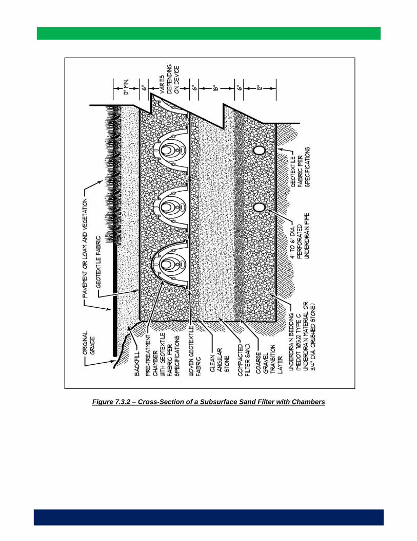
4
Figure 7.3.2 – Cross-Section of a Subsurface Sand Filter with Chambers

5
Pre-Treatment: Because accessing a subsurface filter for maintenance is difficult, protecting the long-term effectiveness of the sand layer is essential, a pre-treatment system that is maintainable must be provided. At this time, only proprietary systems that have been tested and show to have an effective sediment removal rate, long-term effectiveness and access for maintenance are acceptable and pre-approved by the Department. A 5-year maintenance contract for regular seasonal inspection of the system and for the cleaning the device will be required. All proprietary pre-treatment systems must be approved by the Department. The design and sizing of currently approved systems are specified in letters that are found in Appendix B of this manual. Pre-Treatment Flow-Through Structure: Flow-through pre-treatment systems that process or filter
90% of the annual runoff volume from its drainage area without overflowing may be approved. See Figure 7.3.3 representing a subsurface sand filter with a flow-through pre-treatment structure, Figure 7.3.4 for its cross-section.
Pre-Treatment Chamber Structure: A row of chambers wrapped in filter fabric may be provided as pre-treatment. A list of approved pre-treatment chambers is provided in Appendix B. See the graphic representation of a subsurface sand filter with a flow-through pre-treatment structure. In the instance that a pre-treatment chamber row is considered, the following must be provided: o Access/Diversion Structure: An adequately sized structure placed directly in front of the chamber
treatment row is required for inspection and maintenance. This structure should be a minimum of 48 inch wide to allow access to the chambers, and have a weir or elevation overflow manifold. The actual size of the structure may vary based on the weir design, pipe sizes, pipe angles and flow rate over the weir. A second structure and manhole must be provided at the opposite end of the row for maintenance. Additional access structures should be provided when the length of the treatment row exceeds 50 feet.
o Capacity: The pre-treatment row must have the flow capacity of the peak flow from a one-year 24-hour storm event without overflowing.
o Overflow: An overflow before the treatment row should be directed towards additional storage chambers, to a suitable discharge location; but not to the system with the sand filter and underdrain. The elevation of the weir/manifold is typically set between the elevations of the midpoint of the chamber and the top of the chamber.
o Geotextile Filter Fabric Composition: Two layers of a woven geotextile fabric meeting AASHTO M288 specifications or equivalent should be placed between the stone and the pre-treatment chambers for stormwater filtration, a durable surface for maintenance operations (to prevent scour of the underlying stone during high pressure jetting). A layer of either woven or non-woven geotextile is required over the side of perforated chambers to filter flows through the sidewalls.
o Multiple Pre-treatment Rows: A treatment row is required for each inlet point if more than one enters the detention system. If the number of chambers required exceeds the available length of treatment, a second row of chambers can be placed adjacent to the first row. However, separate access structures are required for each row.

6
Figure 7.3.3 - Layout of a Subsurface System with a Pretreatment Row

7
Fig
ure
7.3
.4 –
Cro
ss-s
ecti
on
of
a C
ham
ber
Pre
trea
tmen
t R
ow

8
Outlet: The channel protection volume must be discharged through a network of underdrain pipe placed below the sand filter or through a proprietary filter system approved by the Department. The outlet of the underdrain pipe system should have a single outlet with a diameter that is no greater than eight inches Outlet: The channel protection volume is typically discharged through an outlet control structure with
a weir plate controlling the release rate from the chamber system via a series of orifices or weir crests. The outlet plate is designed to obtain the required 24 to 48 hour release time.
Regulated Outlet Discharge: Outflow of the filter basin underdrain can be controlled by a constrictive orifice or a valve (2” plastic ball valve, type 346, with a ball valve handle extension, type 615, with a three-piece valve box installed over the valve). Upon completion of the installation of the subsurface chamber system, the contractor should flood the vegetated basin to the design elevation with clean water and adjust the outflow to obtain a 24 hour to 48 hour release time.
Connection Pipes: All connection pipes should be 12” in diameter or greater. A chambered pre-treatment row system and the chambers over the sand filter and underdrain should not be connected with a pipe.
Flooding Control Outlet: Flood volumes are typically discharged through an outlet control structure with a weir plate controlling the release rate from the chamber system via a series of orifices or weir crests to manage the peak flow rates.
Downgradient Discharge Area: Each underdrain system must discharge to an area capable of withstanding concentrated flows and saturated conditions without eroding.
Construction: The sand filter media should not be installed until the area that drains to it has been permanently stabilized or the runoff is diverted around the filter until stabilization is completed. Erosion and sedimentation from unstable subcatchments is the most common reason for filter failure. Manufacturers Specifications: The chamber system must be installed in accordance with the
manufacturer’s written instructions for installation. Inspection during and after construction and until the site is stabilized must be performed by the manufacturer’s representative.
Site Preparation: Requirement for subgrade soil bearing capacity should meet or exceed the chamber manufacturer’s allowable subgrade soil bearing capacity.
Basin Excavation: The basin area can be used as a sediment trap during construction before the installation of the subsurface system but the outlet structure and piping system must be protected from sedimentation with a sediment barrier. If the basin is to be used as a sediment trap, the sides of the embankments must be stabilized and maintained to prevent erosion. During the installation of the chamber system and sand filter, the excavation should be free of standing water.
Site Stabilization: The site must be completely stabilized before water is discharged to the subsurface sand filter. Sediments from an unstabilized site affect the design flow rates of the measure and require cleaning prior to system use.
Compaction of Soil Filter: Filter sand media and underdrain bedding material should be compacted to between 90 and 92% standard proctor. The filter should be installed in at least 2 lifts of 9 inches to prevent pockets of loose media.
Construction Sequence: Any runoff from an unstable contributing drainage area should be diverted around the work area until stabilization is completed.
Maintenance: A legal agreement between the owner and an approved maintenance operator should identity the responsible inspector, all inspection and maintenance tasks, and all financial obligations. Maintenance Agreement: A legal contract with a 5 year time period should establish maintenance
responsibilities and the cost to cover long-term inspection and maintenance needs. Pre-treatment Device: Cleaning of the pretreatment device should be performed as identified by the
entity holding the maintenance contractual agreement. A routine but specific inspection schedule needs to be identified for every site based on site variables such as anticipated pollutant load, percent imperviousness, land use (i.e. road, industrial, commercial, residential), etc.
Drainage: The filter should be draining within 48 hours following a one-inch storm or greater. If the system drains too fast, an orifice may need to be added on the underdrain outlet or may need to be modified if already present.
Sediment Removal: The pretreatment structure must be cleaned when necessary.

1
Chapter 7.4 - Gravel Wetlands
The subsurface gravel wetland is designed as a system with two horizontal flow-through treatment cells and a forebay in series and where stormwater passes through a saturated gravel substrate that acts as a natural microbial habitat capable of denitrification (i.e., conversion of nitrate to nitrogen gas). From a process perspective, the forebay is maintained as a dry basin and provides pre-treatment under aerobic conditions, the basins of the wetland cells provide sedimentation and some quality treatment from the wetland plants. Anaerobic treatment is effectively provided by the saturated drainage layer of the cells. A multiple-staged outlet controls the channel protection volume as well as the volume from larger storms. The soil in the cells should remain continuously saturated 4 inches below the ground surface to promote water quality treatment conditions and to support wetland vegetation. Basin Siting: The following criteria apply to all gravel wetlands: Wetland alterations: Any alteration to existing natural wetlands is subject to regulation by the Maine
DEP and the U.S. Army Corps of Engineers and appropriate permits will be required. Natural Soils: The created gravel wetland must remain wet at all time; and either the structure is
located within undisturbed tight soils such as soils Type D or C, below the groundwater table, or the basin structure is lined with an impermeable membrane.
Relationship to Groundwater: The elevation of the created wetland outlet may be at the elevation of the seasonal high groundwater table.
Drainage Area: The size of the underdrained soil filter and storage capacity over the filter is based on the size and land use within the area draining to the structure. Upgradient areas not intended to be treated should be directed around the filter basin.
Basin Sizing: When used to meet the phosphorus allocation in lake watersheds, the sizing of the gravel wetland structure needs to be adjusted in accordance with Volume II of this BMP manual. Water Quality Volume: The created wetland must contain the full water quality volume from one inch
of runoff over the impervious area within the subarea and 0.4 inch over the vegetated or landscaped area. The target detention time for the treatment volume should be between 24 to 48 hours.
Wetland Treatment cells: The two wetland cells must be capable of holding 45% of the water quality volume each and may provide flood storage if necessary.
Forebay: The forebay and any swale or discharge pipe to the system should be capable of holding 10% of the water quality volume.
Surface area: The total surface area of the bottom of the cells needs to add up to 5% of the impervious area plus 2% of the vegetated area draining to the structure.
Treatment Depth: The ponding depth of the treatment volume within the system should not exceed 18 inches over the vegetation.
Storage for quantity control: A gravel wetland may also provide flooding control; but at maximum flood level elevation, ponding should be no deeper than three feet as large changes in water level are not conducive to the growth of wetland plants.
Basin Plan: The following criteria apply to all gravel wetlands. A plan view of a gravel wetland is shown on Figure 7.4.1 and a cross section is shown on Figure 7.4.2. Side slopes: All side slopes to the forebay and the treatment cells should be 3:1 or flatter for
maintenance access. Geotextile Fabric: A geotextile fabric should be placed between the gravel layer and adjacent soil.
The fabric will prevent the surrounding soil from migrating into the trench and clogging the outlet. Use an appropriate mesh size that is compatible with the surrounding soil. Overlap seams should be a minimum of 12 inches.
Impermeable Membrane: A low permeability liner or soil may be necessary to contain the system and prevent infiltration or loss of moisture, preserve horizontal flow within the treatment layer and sustain the wetland plants. If geotechnical testing confirms the need for a liner, an impermeable liner such as

2
Fig
ure
7.4
.1–
Gra
vel W
etla
nd
Pla
n V
iew

3
Fig
ure
7.4
.2 –
Gra
vel W
etla
nd
Cro
ss-S
ecti
on

4
a 30 ml HDPE liner or equal will be necessary. If the undisturbed native soils where the gravel
wetland will be located have a low hydraulic conductivity (such as a soil type D) or the water table is near the top of the basin, a liner will not be necessary.
Wetland Soil: The wetland soil should have a thickness of 8 inches minimum and should have a low hydraulic conductivity (0.1-0.01 ft/day). This soil can be manufactured, using compost, sand and fine soils, into a blend with more than 15% organic matter. It should contain more than 15% silt (passing the #200 sieve); but with a clay size portion that is less than 2%.
Intermediate Layer: An intermediate layer (6 inches thick) of aggregate filter (pea gravel) is needed to prevent the wetland soil from migrating into the crushed-stone (gravel) saturated drainage layer. Do not use a geotextile fabric as it will restrict root growth.
Saturated Drainage Layer: Below the wetland soil and intermediate layer is a crushed stone (or very coarse gravel) drainage layer with a 24-inch minimum thickness. Angular ¾” crushed stone, is recommended as large angular particles are needed to maintain the permeability of the system. The pipe underdrains should have at least 2 feet of gravel cover and six inches below the pipe.
Underdrains: Horizontal underdrains and risers distribute the inflow through the gravel layer within each of the cells; and at the downstream, an outflow underdrain recollects the water to distribute it to the next cell or for discharge.
Treatment length: The flow path between the inflow and the outflow subdrains within each cell’s saturated drainage layer should be 15 feet at a minimum.
Outlets: The channel protection volume must be discharged solely through the underdrained gravel outlet having a weir or a single elbowed pipe outlet placed at the elevation of the wetland basin to force a near-surface groundwater condition (with as an invert 4 inches below the wetland ground surface). The outlet needs to be sized to provide the slow discharge (24-48 hours) of the water quality volume. Risers: In both wetland cells, vertical perforated or slotted risers deliver the outflow to the horizontal
and perpendicular sub-drains imbedded in the gravel drainage layer. The perforated/slotted riser should extend 18-24 inches above the surface of the wetland soil. A riser should be provided for every 10 feet of linear inflow sub-drain.
Underdrain Pipe: The underdrain piping should be 6 inch diameter with slotted, rigid Schedule 40 PVC or SDR35 pipe.
Overflow Spillway: An armored spillway should be provided between the cells for larger storms to flow through without causing erosion. The spillway should be 18 inches above the wetland surface.
Emergency Spillways: Emergency spillways should be designed to independently convey the routed runoff from larger storms ( 2, 10 and 25-year, 24-hour storms) while maintaining at least one foot of freeboard; and to safely convey the 100-year storm without overtopping the embankment. Overflow must discharge to a stable channel or vegetated area. The emergency spillways should be located on undisturbed, non-fill soil wherever possible. If the spillway must be located on fill soils, then it must be horizontally offset at least 20 feet from the principal outlet and appropriately stabilized.
Cleaning Ports: A clean-out port should be provided for each of the horizontal underdrain pipe structure in both basins.
Vegetation: Appropriate wetland species should be carefully selected to stabilize the sides and bottom of the basins. The creation of a marsh environment at the pond inlet will help to trap sediment. Fertilizer should not be used unless necessary to establish new vegetation. Allowing for the natural invasion of native species may encourage healthier growth than planting species not already found on site. Wetland Plants: Wetland plants function in two important ways: the stems and leaves provide a large
surface area for the attachment of microbial populations; and the plants transport oxygen to the root zone. The by-products produced by the aerobic microbes are then easily utilized by the anaerobic microbes in the saturated layer. Leaves and stalks provide a canopy of shade, which limit sunlight penetration and alga growth (the algae can deter the oxygen transfer and creates a toxic environment for the plants). The most appropriate wetland plants are the following: o Reeds (Juncus effusus) are the “worker plants” in a gravel wetland. Their roots go down quickly
and deeply. They spread across the media and they are pest resistant and winter hardy.

5
o Cattails (Typha latifolia) are the plants most often associated with wetlands. They work well and have a positive impact on treatment. The larger, native varieties, however, can be dominant and take over a small filter if not removed in later years.
o Bulrush (Scirpus) can produce dense stands of vegetation. It can survive unfavorable conditions like prolonged flooding, or drought as buried seeds.
o Phragmites (reed) is very invasive and is not recommended. Construction: The subarea draining to a created wetland must be completely stable before runoff is directed to the basin to prevent sedimentation of the drainage layer; or all runoff should be re-directed until construction is finalized. The vegetation within the structure is equally important and must be well established before it can accept any runoff. Construction should be started no later than September 1 or earlier than June 1; and if vegetation cannot be established by the end of the growing season, construction should be delayed to the following year. Seeding or stabilization must occur by September 15 in preparation for the winter season. Oversight: A gravel wetland should only be constructed under the supervision from the design
engineer. Maintenance: Operation and maintenance requirements similar to those for underdrained filter basins should be expected. The plant biomass should be harvested annually, and accumulated sediment removed at intervals of 5-10 years. These activities may disrupt the wetlands system and may require some vegetation re-establishment. The riser pipes may clog and will require annual clean-out (it should be done in the winter time when one can walk on the wetland). First Year Post-Construction: Inspection frequency should occur after every major storm in the first
year following construction. o Inspect that the system drains within 24-48 hours. o The plants may need watering if necessary during the first growing season. Revegetate if the
vegetation is poorly establishing. o Identify areas of erosion and make timely repairs. o Check all inlets, outlets and subdrains for proper functioning. Risers may need to be cleaned.
Post-Construction: Inspection frequency should occur at least every 6 months and after every major storm. Activities are expected to include:
o Check the basin for a dense root mat establishment of wetland vegetation. o Check and clean the risers if there is evidence of standing water, discolored water or
accumulated sediments in the cells. o Check and clean the forebay for sediments, trash and debris. When sediments have
accumulated to a depth of 12 inches, standing water is persistent or wetland vegetation become established, the forebay will need to be excavated and reformed.
o Verify that the cells drain within 24-48 hours. Sediment will need to be removed when an accumulation of 4 inches is evident over the wetland surface.
o Check and clean all outlets and overflow spillway if blocked or there is evidence of structural damage or erosion.
o Remove decaying vegetation, litter and debris. o Check for foreign species. Particular care must be used to avoid the unintended introduction
of invasive species such as purple loosestrife (Lythrum salicaria) and common reed (Phragmites australis). It is recommended that a qualified wetland biologist be consulted when these are found in the area of the gravel wetland.

Chapter 7.5 - Roof Dripline Filters
The runoff from a peaked roof without gutters may be detained at the drip line, be filtered through the foundation backfill and be discharged via a foundation underdrain pipe or equivalent. The roof dripline filtration BMP needs to be designed with the following criteria: BMP Components: The roof dripline filtration BMP consists of the following layers in ascending depth order: a reservoir layer of crushed stone, a drainage layer of sand, a filter layer of mineral soil with 4 to 7% fines, and an underdrain layer with perforated underdrain pipe to gravity outlet. The BMP extends the length of the building or area of roof to be treated.
Figure 7.5.1 – Roof Dripline Cross-Section
Capacity for large storm: To meet the Chapter 500 Flooding Standards requirements, the reservoir needs to provide a minimum storage capacity for the direct entry of the rain precipitation from a 24-hour, 25-year storm (5 + inches) or an overflow may be needed or provided for. Treatment Storage: The reservoir layer at the drip line must consist of crushed stone with a porosity of 40%. Its width and depth (4” min to 12” max) is sized based on the runoff volume from the roof. For example, a 30 foot wide roof panel will need a 6.3 foot wide by 1 foot deep reservoir to store the first 1-inch of runoff for treatment. Drip line edge: The drip line trench should extend the length of the building or area of roof. Treatment Storage: The reservoir bed at the drip line should be sized based on the runoff volume from the roof (For example, a 30 foot wide roof panel will need a 4 foot wide by 1.5 foot deep rock storage bed. Reservoir Layer: The reservoir layer should consist of clean washed stone meeting the requirements of MaineDOT Standard Specification 703.22 Type C Underdrain Stone. The depth of the reservoir course shall be based on the desired storage volume. Drainage Layer: The drainage layer should consist of a free draining sand meeting the requirements of MaineDOT Standard Specification 703.22 Type B Underdrain Backfill as necessary to provide frost protection for the foundation. Crushed stone may not be substituted.

Filter Layer: The backfill for the foundation may be used as the filter media as long as the material is a mineral soil with between 4 and 7% fines (passing #200 sieve) and is at least 4 inches thick. Underdrain Layer: An underdrain layer consisting of a 4” diameter slotted underdrain pipe bedded in 8 to 12 inches of underdrain backfill material (MaineDOT Specification 703.22 Type B Underdrain Sand or Type C Underdrain Stone wrapped in filter fabric). Frost Protection: Frost depth is measured from the bottom of the porous stone of the reservoir layer. Basement Waterproofing: To prevent the penetration of water into a basement, the basement wall should be waterproofed. Filter Sizing: A minimum storage capacity within a porous reservoir layer is needed to allow for the treatment of one inch or more of runoff and should have a minimum storage capacity for the direct entry of the rain precipitation from a 24-hour, 25-year storm (5 + inches) or an overflow needs to be provided. Detention Time: Stored volume needs to fully drain within 24 to 48 hours. An orifice may be needed to regulate the outflow. Additional Storage: The reservoir layer may be increased and the drainage layer may be used to store runoff after the first 1-inch of runoff assuming a porosity of 20% for Underdrain Sand. For example, a 3 foot thick drainage layer that is 6.3 feet wide at the top and 3 feet wide at the bottom can store 1.1 inches of runoff from a 30 foot wide roof panel. Overflow: An overflow should be provided for runoff above the combined capacity of the reservoir and drainage layers. Maintenance: A dripline filter bed needs to be maintained like any other filter basin. The maintenance activities for filtration BMPs listed in Chapter 7.2 of the BMP manual apply equally to this type of structure. Any debris must be removed from the reservoir course. The Maintenance plan needs to address that these structures are part of the stormwater management plan for the project, cannot be paved over or altered in anyway. No gutter may be installed on the roof line.

Chapter 7.6 - Vegetated Roofs
Rooftop vegetation provides three primary benefits: attenuation of stormwater runoff and peak flows, reductions in the heat island effects with significant improvements in building insulation, and a substantial increase in the life expectancy of the base roof material. As an added benefit, vegetated (or green) roofs absorb smaller storm events by minimizing peak and volume of stormwater runoff. The runoff from a flat roof may be detained and treated within a layer of filter media and vegetation and will meet the required treatment under the General Standards of Chapter 500. There are two primary types of green roofs: extensive and intensive. The term "extensive" represents the practice of covering the entire roof area with a vegetative mat. These systems are lightweight with only a few inches of growth media; and the vegetation is limited to various species of sedums or other similar arid plants. Due to the shallow media, the roofs have little organic substrate to retain potential pollutant loads. The term "intensive" represents additions to the roof for access and use of the rooftop as open space for the building inhabitants. Intensive roof landscaping runs the gamut from small city parks to commercial use such as sidewalk cafes, etc. This type of green roof typically requires more growth media and significant additional weight loading to the roof structure; but it provides for more nutrient uptake and greater flow attenuation. One point of consideration is that thin media green roofs provide little treatment. The initial flow from rainwater typically contains elevated levels of organic constituents such as nitrogen and phosphorus; and residual stormwater detention tanks with a pump back system can be used to recirculate rainwater for watering the media during dry periods, providing for additional uptake of first flush pollutants and summertime evaporative cooling. The inclusion of a containment structure significantly improves stormwater water quality and enhances the overall effectiveness of the green roof technology. In summary, typical green roofs include the planting media, a protective geotextile liner, and a root barrier membrane that consists of an impermeable membrane. A structural engineer should be consulted to ensure the building can support the added weight from the planting media and vegetation. Roof Design: Roof Slope: A minimum slope of 2% is considered normal for extensive and simple intensive
greening. In extensive greening, controlled drainage will meet the basic needs of the vegetation. Roofs with less than 2% slope will require special measures. Extensive greening on roofs with less than 2% slope requires a drainage course to avoid water logging in the vegetation support course.
Roof Structural Strength: The building and roof will need to be designed for the additional bearing load equivalent to 3 inches of water.
Design Loads: The design load of the building is the critical factor in deciding what type of greening to use and how to cultivate the vegetation. All the courses must be considered, at maximum water capacity and including the surface load generated by the vegetation, as a component in the surface load. Spot loadings generated by large scale bushes, trees and structural components, such as pergolas, water storages and peripheral items, will need to be calculated separately.
Joints and Borders: Joints and borders include joints with facades and other vertical structural components, joints where the roof is penetrated, and borders at roof edges. Damp-proof lining/root-penetration barriers should be brought up to 15 cm high for a roof slope of up to 5° and 10 cm high for a roof slope of over 5°. As a rule, a strip made up of slabs or gravel

should separate the vegetation area from the structural border with a minimum height of 10 cm high for a roof slope of up to 5° and 5 cm high for a roof slope of over 5°.
Wind Loads: Wind can generate positive and negative pressure forces, or friction on the green roof. The strength of these forces is a direct function of wind strength and direction and of the shape and height of the building in question.
Protection Against Slipping and Shearing: Where a roof slopes at an angle in excess of 2:1, structural anti-shear protection will normally be needed without creating tension at the point of contact with the damp-proof lining and the root-penetration barrier.
Lip Edge: A lip will need to be provided at the edge of the roof to control drainage and to prevent the filter media from sliding off the roof.
Impermeable Roof Cover: The roof will need to be protected with an impervious cover Root Penetration: Both intensive and extensive green-roof sites must have lasting protection
such as protective sheeting or full surface treatment/liquid coating against root penetration. Damp-proof linings and root-penetration barriers on roofs can be protected against mechanical damage by protective non-woven fabrics, boards, sheeting or drainage course.
Underdrain Mat: The drainage layer will consist of a mat that is covered with a filter fabric. This product is available through vendors of manmade erosion control measures.
Figure 7.6.1 – Vegetated Roof Cross-Section
Growing Medium: The vegetation support course should accommodate a dense root stock and have all the physical, chemical, and biological properties needed for plant growth. Available materials include: Soil mixtures - improved top and
underlying soil Aggregate mixtures - mineral
aggregate mixtures with high or low organic content or with an open-pore granular structure with no organic content
Substrate boards -boards made from modified foam materials or mineral fibers
Vegetation matting - matting with mineral/organic aggregate mixtures. The organic content of the vegetation support course should be as shown on Table 7.6.1.
Table 7.6.1 – Growing Medium
Type of Greening Substrate Density
Organic Content
Intensive Greening < 0.8 > 0.8
< 12% by mass < 6% by mass
Extensive Greening Multiple-Course
Construction < 0.8 > 0.8
<8% by mass < 6% by mass
Single-Course Construction
N/A < 4% by mass
The Landscaping and Landscape Development Research Society E.V. - FLL

Treatment Filter: The filter media will meet the specifications of the media for underdrained soil filters with equivalent organic material and with a porosity of 30%. The filter bed must be a minimum of 3 inch thick with between 4 and 7% fines (passing #200 sieve).
Vegetation: A perennial plant or grass that is draught resistant and flood resistant will need to be selected for vegetation cover. The most appropriate plants are the one that need low maintenance and are prolific. The best plants will have a thick shallow root mat Acceptable options may be found in the sedum family and are shown on Table 7.6.2. Additional Watering: Green-roof sites are designed to depend chiefly on precipitation for their
water supply. Additional watering may be provided through the use of a spray or dip type hose, hose and sprinkler, an overhead irrigation system, or automated water systems controlled by a timer.
Plant Compatibility: Materials must not contain any components which are harmful to plant life and which are capable, over a given period, of finding their way out into the environment.
Drainage: Drainage must be available through the layered superstructure and off the surface. Excess water may be drained within the vegetation area, outside the vegetation area, or through separate drainage facilities for areas which have undergone greening and those which have no vegetation. Regardless of the size of the roof surface, roofs with drainage facilities located within the vegetation area must have at least one run-off facility and at least one emergency overflow. Drainage System: The drainage system should collect the overflow from the drainage course,
and surface water from the vegetation support course. Materials include roof outlets, guttering, downpipes, and emergency overflows.
Overflow: An overflow measure must be provided for the runoff from larger storms. Filter Course: The filter course should prevent fine soil and substrate components from
washing out of the vegetation support course into the drainage course. Nonwoven geotextile fabrics are typically used as filter courses.
Drainage Course: The drainage course should contain sufficient voids to uptake any excess water. Course materials and dimensions will depend on construction requirements and objectives for the vegetation. The drainage course may be constructed of: o Aggregate-type materials - gravel and fine chippings, lava and pumic, or expanded clay
and slate o Recycling aggregate-type materials – brick hardcore, slag, or foamed glass o Drainage matting - textured nonwoven matting, studded plastic matting, fibre-type woven
matting, or flock-type foam matting o Drainage boards - boards made from foam pellets, studded rubber boards, shaped rigid
plastic boards, shaped plastic foam boards o Drainage and substrate boards – boards made from modified foam
Table 7.6.2 – Roof Top Vegetation Type
Objectives Course Depth (cm)
Form of Vegetation
% Water Retention
Annual Average
Extensive Vegetation
2-4 >4-6 >6-10 >10-15 >15-20
Moss-sedum greening Sedum-moss greening Sedum-moss-herbaceous plants Sedum-herbaceous-grass plants Grass-herbaceous plants
40 45 50 55 60
Intensive Vegetation
15-25 >25-50 >50
Lawn, shrubs, coppices Lawn, shrubs, coppices Lawn, shrubs, coppices, trees
60 70
>90 Reference: The Landscaping and Landscape Development Research Society E.V. - FLL

Water Retention: The annual water retention on green roof sites should be a function of the course depth is provided in the table below.
Water Storage: Water may be stored in the vegetation support and drainage courses: Storage in the vegetation support course through the use of substances which retain water
for vegetation substrates or prefabricated substrate boards Storage in the vegetation support course and in the drainage course, through the use either
of open-pore type aggregate materials in graded granular sizes or of prefabricated draining substrate boards
Storage in the vegetation support course and in the drainage course, by allowing a water supply to build up in the aggregate over the entire area or by using pre-formed drainage boards with partial retention characteristics
An underdrain layer is needed to drain the filtrated water. Stored volume needs to fully drain within 24-48 hours. To meet the General Standards requirements (treatment of 1 inch of runoff), a minimum storage capacity within the filter layer is needed to allow the treatment of one inch or greater of runoff.
MAINTENANCE CRITERIA A green roof needs to be maintained like any other soil filter structure. The maintenance activities for filtration BMPs listed in Chapter 7 of the BMP manual apply equally to this type of structure. Replacement of the vegetation will be required if it is found to be unhealthy, dying and with soil showing though. Vegetation Upkeep: The more complicated and intensive the green roof, the more
maintenance associated with caring for the vegetation, whereas an extensive roof planted in sedums can represent little or no maintenance other than a periodic feeding during the first year of operation.

Chapter 7.7 - Manmade Pervious Surfaces
Porous pavement consists of the use of a permeable surface, base, and subbase materials which allow penetration of runoff through the surface and into the underlying soils. Pavement alternatives vary in load bearing capacities but are generally appropriate for low traffic areas such as sidewalks, parking lots, overflow parking and residential roads. It is important to choose a material appropriate for the desired use (light, moderate or heavy use). Maintenance is essential for long term use and effectiveness. The efficiency of pavement alternative systems will depend on whether the pavement is designed to store and infiltrate most runoff, or only limited volumes of runoff (e.g., "first-flush") with the remainder discharged to a storm drainage system or overland flow. The effectiveness of pavement alternatives will also depend on the long term serviceability. This manual describes three different permeable pavement alternatives (porous asphalt or concrete, block pavers, and plastic grid pavers) Examples of these porous pavement alternatives are shown below. Refer to Chapter 9.0 for further information on the performance and design of level spreaders.
Types of Porous Pavement: A typical permeable pavement alternative consists of a top porous asphalt, block pavers or plastic grid paver course, a filter course, a reservoir course, a geotextile filter fabric and existing soil or subbase material. Some materials will be more resilient to intended use and site conditions; and the selection of a type of paver alternative must be carefully considered. A brief description of three types of porous pavements is provided below and a comparison provided in Table 7.7.1.
Porous Asphalt: Porous asphalt is very similar to conventional asphalt except that it is mixed without particles smaller than coarse sand (less than 600 μm or No. 30 sieve). Without these smaller size particles, water is able to pass through the surface and into a crushed stone storage area which allows the water to slowly infiltrate into the ground. The lack of fine particles in the material limits the load capacity of the asphalt compared to conventional asphalt thus it should not be used for areas of high traffic.
Block Pavers: Block pavers consist of a set of interlocking, normally concrete pavers that connect in a way to leave open or void spaces between them to allow water to infiltrate into the underlying gravel reservoir. Typical installation consists of a soil subgrade, a gravel subbase, a layer of sand, and the grid pavers. The infiltration capacity is based on the thickness of the gravel subbase and the material in the void space. Void spaces can be filled with gravel or soil and grass.
Plastic Grid Pavers: Plastic grid pavers are often constructed from recycled material. They generally come in a honeycomb pattern and the voids are filled with either gravel or soil and grass depending on use. The grid pavers give added stability to and allow minimal compacting of soils in voids. They are flexible and can be used in areas with uneven terrain.
Artificial ball fields (turf athletic fields): These are also considered pervious surfaces that require similar design considerations. The synthetic nature of the turf may be a concern for the infiltration of chemicals into the subsurface; however, no restriction will be applied until more data is available on this subject.
Siting Plans: Soils: Pavement alternatives are not suitable when on soils with field-verified permeability
rates less than 0.50 inches per hour or with clay content that is greater than 30%. Soil borings must be taken two to four feet below the level of the base of the pavement system or the bottom filter course, whichever is deeper, to identify any restrictive layers. Frost-susceptible soils or on wet or unstable subgrade of fill soils prone to slope failure are not good candidates. Sites without suitable natural soils for infiltration may be used for pavement
alternatives, but will require provision of subsurface drainage and a discharge outlet from the system for the treated percolate.

Traffic Volumes: Pavement alternatives are limited to areas with light to moderate traffic. They are not recommended for most roadways, and cannot withstand heavy vehicles.
Off-site Runoff: Any off-site runoff directed to the system has to be pretreated to prevent the clogging of the pavement structure and underlying soils.
Grading: The site should slope with less than 5% and preferably closer to 1%. Sediment loading: Pavement should not be used in areas expected to receive high levels of
sediments as they are highly susceptible to clogging. Reservoir Course: The reservoir course should consist of clean washed 1½ to 3-inch
aggregate. The depth of the reservoir course should be based on the desired storage volume and frost penetration.
Porous Asphalt Course: The top porous asphalt course should be 2-4 inches thick, depending on load and traffic application. A typical porous asphalt mix is provided in Table 7.7.2. The porous asphalt mix and thickness should be designed based on site specific conditions such as the use of the paved area, the required load bearing capacity, climate, etc.
Asphalt Mix: Porous asphalt is weaker than conventional asphalt pavement; however with the proper admixture design and installation, its durability has shown to be effective for both commercial and roadway applications. The following mixtures are available: o Low/Moderate Durability: PG 64-28 with 5 pounds of fibers per ton of asphalt mix. This
mix is recommended for smaller projects with lower use or loading potential.
Table 7.7.2 - Comparison of Porous Pavement
Porous Asphalt Block Pavers Plastic Grid Pavers
Application and Use
Parking Areas Parking Areas Parking Areas Walkways/ Bike Paths Walkways/ Bike Paths Walkways/ Bike Paths Overflow & Event Parking
Overflow & Event Parking
Overflow & Event Parking
Driveways/Patios/Fire Lanes/Emergency Access
Driveways/Patios/Fire Lanes/Emergency Access
Driveways/Patios/Fire Lanes/Emergency Access
Light Traffic Roadways Light Traffic Roadways
Design Strength 259,200-345,600 lbs/ft2 - slightly less than porous concrete
Per manufacturer Per manufacturer ~24,000-820,000 lbs/ft2
Life Span 15-20 yrs Per manufacturer Per manufacturer
Subbase
Geotextile fabric topped with 18-36” of crushed stone and 1”chocker course
Geotextile topped with 6” or more of gravel (omitted in residential areas) and 1” sand bedding
Varies based on manufacturers - Some grids are filled with either gravel or grass.
Maintenance
Periodic vacuum-sweeping
Refill voids/replace damaged blocks
Refill voids/replace damaged sections
Fill potholes with patching mix unless >10% of surface
Seed low grass Seed and mow grassed sections
Drill 0.5” holes to address spot clogging
Remove and replace Remove and replace
No winter salt/sanding No winter salt/sanding No winter salt/sandingRaise plow blade 1” above surface
Raise plow blade 1” above surface
Raise plow blade 1” above surface
Table 7.7.2 - Typical Porous Asphalt Gradation
Sieve Size % Passing 1/2” 100 3/8” 95 #4 35 #8 15 #16 10 #30 2

o Moderate Durability: Prep-blended PG 64-28 SBS/SBR with 5 pounds of fibers per tons of asphalt mix. This mix is for large projects (>1 acre) where high durability pavement is required.
o High Durability: Pre-Blended PG 76-22 modified with SBS/SBR and 5 pounds of fiber per ton of asphalt mix. This mix is recommended for large sites with high wheel load (H-20) and traffic counts.
Geotextile Fabric: A geotextile fabric may prevent surrounding soils from migrating into the system and reducing its storage capacity. Choose a compatible fabric that is free of tears, punctures, and other damage. Overlap seams a minimum of 12 inches.
Filter Course: A filter course should be provided between the top porous asphalt or paver course and the reservoir course. This provides a level surface to construct the top porous asphalt or paver course. The filter course should meet the following requirements:
Cold Climates: Winter maintenance procedures may be problematic (e.g., scraping by plows, clogging by sand, clogging by or inability to treat de-icing chemicals). Snow removal and deicing activities should be done carefully to avoid disturbance to the pavement structure and stripping of any vegetation. The plow blade should be raised 1" above the surface or outfitted with a flexible rubber bottom piece.
Figure 7.7.1 – Types of Pervious Pavement

Design for Infiltration: All specifications from Chapter 6, Infiltration apply: At a minimum, one foot separation is needed below the
road subbase and above the groundwater table. The depth of the water table elevation needs to be considered in designing the road for sufficient frost protection depth.
A filter layer providing pretreatment before infiltration to groundwater can be part of the subbase and base. It should be 8 inches minimum, mostly granular; but with 4 to 7% fines (passing #200 sieve), and should extend across the bottom of the entire filter area. This material should be uniform, free of stones, stumps, roots, or other objects larger than two inches. The preferred material should meet the specifications of a MEDOT aggregate (MEDOT # 703.01) as shown on Table 7.7.3. However, more fines would be preferable (between 8% and 10% fines passing the #200 sieve).
A reservoir course within the filter layer or subbase and base is needed to allow the direct entry of one inch or more of water.
The road design may provide the storage capacity for the direct entry of rain precipitation from a 24-hour, 25-year storm (5+ inches) event.
Infiltration rate should be confirmed with a double ring infiltrometer test to determine the soil’s permeability. The test needs to be on native subgrade even if there is fill above it, and not on the fill itself. Recommended infiltration should be less than 2.41 inches per hour but great enough that one inch of stored precipitation infiltrates in 24 hours (i.e. >0.04 inches per hour).
The stored volume needs to fully infiltrate within 24-48 hours.
Provide appropriate drainage and discharge of flows from larger storms where is needed.
Design for Storage and Filtration: All specifications from Chapter 7, Filtration apply; and a minimum storage capacity for one inch of precipitation within the filter layer or subbase and base is needed. To meet the Chapter 500 Flooding Standards requirements, the road design needs to provide
a minimum storage capacity for the direct entry of the rain precipitation from a 24-hour, 25-year storm (5 + inches).
The filter bed may be part of the road base and subbase horizon. The filter must be a mineral soil with between 4 to 7% fines (passing # 200 sieve) and must be a minimum of 4 inches thick.
The underdrained layer, 12-inch thick of underdrain gravel meeting the MDOT Specification 703.22, Type C as shown on Table 7.7.4, should provide sufficient coverage for the underdrain piping.
An underdrain pipe network is needed to drain adequately the underdrain layer. Pipes should be placed perpendicular to the slope and should be spaced no further than 20 feet apart. An orifice may be needed to control the outflow.
Stored volume needs to fully drain within 24-48 hours. Provide appropriate drainage and discharge of flows from larger storms where is needed.
Table 7.7.3 - Maine DOT Specifications for Aggregate
(MEDOT #703.01)
Sieve Size % by Weight
3/8” 100
#4 95-100
#8 80-100
#16 50-85
#30 25-60
#60 10-30
#100 2-10
#200 0-5 (8-10% is preferred)
Table 7.7.4 - Maine DOT Specifications for Underdrains
(MEDOT #703.22)
Sieve Size % by Weight
UNDERDRAIN - TYPE B
1” 90-100 ½” 75-100 #4 50-100 #20 15-80 #50 0-15 #200 0-5
UNDERDRAIN - TYPE C
1” 100 ¾” 90-100 3/8” 0-75 #4 0-25 #10 0-5

Figure 7.7.2 – Pervious Pavement Cross-Section
7.7.1 - Run-on Modular Pervious Pavement In addition to the design guidelines from above, an area of modular pervious pavement structure may be used to provide the treatment of impervious pavement where the area of pervious pavement is no less than 20% of the impervious area that drains to it. However, the thickness of the filter sand layer must be equivalently increased, and must meet the following design criteria: The thickness of the sand filter layer should be increased exponentially from 4 inches for a
full (100%) pervious pavement section with no run-on from other areas to 18 inches for a pervious section and treatment system that is no less than 20% of the impervious area draining into it.
The flow path over the impervious area should not exceed 50 feet before reaching the pervious pavement section for treatment.
Subsurface storage and a drainage structure must be provided to control the channel protection volume for a 24-48 hour discharge unless the system is designed for infiltration. Long-term inspection and maintenance by a DEP approved stormwater maintenance inspector will be regularly provided under a five-year binding inspection and maintenance contract that is renewed before contract expiration.
The replacement of the modular pervious system will be provided when more than 40% of the pervious system shows signs of clogging.
7.7.2. - Run-on Asphalt Pervious Pavement An area of asphalt pervious pavement may be used to provide the treatment of regular asphalt pavement that is impervious may be used with the following criteria: The area of pervious pavement is equal in length of the impervious area that drains to it, but
the flow path over the impervious area should not exceed 50 feet before reaching the pervious pavement section for treatment.
The minimum thickness of the filter sand layer is 12 inches.

Subsurface storage and a drainage structure must be provided to control the channel protection volume for a 24-48 hour discharge unless the system is designed for infiltration. And, the system is sized to meet the requirements for flooding control if required.
Long-term inspection and maintenance by a DEP approved stormwater maintenance inspector will be regularly provided under a five-year binding inspection and maintenance contract that is renewed before contract expiration.
The pervious pavement will be replaced when more than 40% of the pervious system shows signs of clogging.
Figure 7.7.3 – Run-On Pervious Pavement
Maintenance: Pervious surfaces and pavement, whether asphalt, concrete or paving stones, have the potential to become impervious if not properly maintained. The following need to be planned for and be met: Frequent inspections are performed during the first few months following construction. Then,
the system is inspected routinely on an annual basis. Inspections should be made after significant storm events to check for surface ponding that could indicate failure due to clogging. Non-routine maintenance may require reconstruction of the surface treatment, and possibly the filter and reservoir layers, to relieve major clogging.
Prevent sedimentation due to the erosion of areas upgradient the pervious pavement structures.
Prevent vehicles with muddy wheels from accessing onto areas intended for pervious pavement.
Sweep, vacuum and/or pressure wash pavement twice annually at a minimum. Limit salt use for deicing, and do not use sand. Remove leaves and organic debris in the fall. Measures should be taken to ensure that an area designed to be porous does not receive a
future overlay of conventional non-porous paving.

Chapter 8– Conveyance and Distribution Systems
Many of the water quality BMPs discussed in this manual rely on conveyance and distribution systems to adequately get the water to the BMP. Swales are excellent alternatives to conventional curb and gutter design for roadways and are generally less expensive to install, where road gradients and availability of land within or adjacent to the right-of-way allow.
IMPORTANT: Conveyance and distribution systems are used to divide flow into two or more parts; they do not provide any water quality treatment or quantity control and should be designed by someone familiar with hydraulics. This chapter discusses some of the more common conveyance and distribution systems including:
• Vegetated Swale • Flow Splitter • Level Spreader • Permeable Road Base

8.1 - VEGETATED SWALE Vegetated swales are broad shallow earthen channels where the combination of low velocities and vegetative cover promotes some settlement of particulates and some degree of treatment by infiltration. Check dams create small infiltration pools along the length of the swale, which are used to retard and temporarily impound runoff to induce infiltration and promote filtering and settling of nutrients and other pollutants. Site Suitability: The proper siting of a swale can enhance the pollutant removal efficiency. Vegetated swales are most applicable in residential or institutional areas where the percentage of impervious cover is relatively small. Roadside swales become less feasible as the number of driveways requiring culverts for swale crossings increases. Slopes: Areas with steep slopes may limit the use of swales. In such areas, swales should
parallel the contour, in effect becoming diversions. If the slopes are too steep, the construction of low velocity swale cross sections may involve excessive disturbance of existing grades to provide stable back slopes.
Flow Volume/Velocity: Vegetated swales are most effective when the flow depth is shallow and the velocities are low.
Using Natural Swales: Existing channels should only be used when they conform to the same design requirements of new systems. Existing ditches should be checked to ensure that they have adequate capacity and that their channels are stable. Gullied, natural channels should be avoided where they are impractical to stabilize.
Separation from Seasonal High Water Table & Bedrock: The recommended depth to seasonal high groundwater or bedrock for a swale is a minimum of 3 feet.
Design and Construction: Swales should not be kept wet for long duration for effective removal of stormwater pollutants. Good management practices include the reduction of the peak rate of runoff and the volume of water. Effective erosion control practices will limit the pollutant loading to the waterway. Soils: Soils should be suitable or amended to establish a vigorous stand of vegetation. If
dense vegetation cannot be maintained in the swale, its effectiveness will be severely reduced. Sites on A or B hydrologic group soils will be more effective for infiltration, although swales on other soils will still provide some treatment through sedimentation.
Equipment Access and Crossings: If the swale or waterway must be crossed or maintained with large equipment, the width should be increased and flatter cross-section incorporated into the design. Large mowing equipment may require a significant increase in width over that needed for hydraulic capacity and freeboard. Easements of sufficient width to allow access by equipment (typically 15 feet minimum) must be provided on either side of the swale.
Flow Velocity: The channel should be designed for low velocity flow. A velocity of 1 fps is the maximum design storm flow velocity recommended when vegetated swales are being designed as a BMP. Higher velocities might be permissible for channel stability, but could result in resuspension of settled particulates. The maximum allowable Q10 (10-yr frequency 24-h duration storm) velocity should be less than 3 fps.
Flow Depth: Flow depths in the swales should be minimized to increase the amount of vegetative filtering and settling. A maximum design flow depth of 1 foot is suggested. This will generally result in wide, shallow channel designs.
Minimum Channel Dimensions: The minimum width of the flat bottom of a trapezoidal channel shall be at least 3 times the channel depth. Non-trapezoidal channels should have similar depth to width relationships. Channel sideslopes shall not exceed 3 (horizontal):1 (vertical) for seeded or sodded slopes, or 2:1 for riprap slopes, although the channels may be parabolic or trapezoidal (Maryland, 1984). A V-shaped swale is not recommended.
Pipe Separation: Provide a minimum of 2 feet of soil between the bottom of the swale and the top of an underdrain pipe.

Vegetation: Vegetation for swale linings should be selected based on soils and hydrologic conditions at the site. Recommended grasses include Ky-31 tall fescue, reed canary grass, redtop, rough stalked blue grass, and mixtures thereof.
Check Dam Design: Check dams will decrease flow velocity and increase infiltration and can be very useful on steep slopes or on slopes with loose soils. The details of check dams within a vegetate swale are shown on Figure 9.1.
o Channel Bottom: The area just downstream of the check dam should be protected from scour with rock riprap or protective channel lining. The check dam may have a solid level surface integrated into it for added durability.
o Check Dam Construction: Check dam heights are generally 6 to 12 inches, depending on channel slope and desired storage capacity. Check dams should be constructed of unerodable rock or rock-lined material and should be notched or ported to allow the flows in excess of their infiltrative capacity to be bypassed.
Construction Considerations: Construct and stabilize the waterway in advance of any other channels or structure that will discharge into it. Divert all flow from the waterway during the establishment of vegetation.
Maintenance: The area should be inspected for failures following heavy rainfall and repaired as necessary for newly formed channels or gullies. Bare spots should be reseeded or resodded. Trash, leaves and/or accumulated sediments should be removed. Woody or other undesirable vegetation should be controlled. Check dam integrity should be checked. Aeration: The buffer strip may require periodic mechanical aeration (by rototilling or other) to
restore infiltration capacity. This aeration must be done during a time when the area can be reseeded and mulched prior to any significant rainfall.
Mowing: Grass should not be trimmed extremely short, as this will reduce the filtering effect of the swale (MPCA, 1989). The cut vegetation should be removed to prevent the decaying organic litter from adding pollutants to the discharge from the swale. Mowed height of the grass should be 2-4 inches taller than the maximum flow depth of the design water quality storm. A minimum mow height of 6 inches is generally recommended (Galli, 1993).
Erosion: It is important to install erosion and sediment control measures to stabilize this area as soon as possible and retain any organic matter in the bottom of the trench.
Fertilization: Routine fertilization and/or pesticide use is strongly discouraged. If complete re-seeding is necessary, half the original recommended rate of fertilizer should be applied with a full rate of seed.
Sediment Removal: Level of sediment deposition in the channel should be monitored regularly, and removed from grassed channels before permanent damage is done to the grassed vegetation, or if infiltration times are longer than 12 hours. Sediment should be removed from a channel when it reduces the capacity of the channel.
Figure 8.1 – Swale
with Check Dams

8.2 - FLOW SPLITTER A flow splitter is engineered to divide flows into two or more directions using devices such as pipes, orifices, and weirs set at specific elevations. Generally, a flow splitter will have a small storage area with one inlet and two outlets set at different elevations. The lower outlet conveys low flows, such as the flow during a small storm or the flow at the beginning of a large storm. The higher outlet conveys high flows that occur later in a larger storm. Water Quality Treatment - A flow splitter can separate the first flush volume which can
contain most of the runoff pollutants; and provides it a longer treatment time in a treatment structure. Without a flow splitter, the first flush would be pushed out the outlet by the following runoff before the pollutants are removed.
Water Quantity Control - A flow splitter can split the runoff to alleviate downstream flooding or it can also be used to prevent a BMP, such as a wet pond, from overtopping and eroding from excessive flows during large storms. This can reduce the needed storage capacity.
Design and Construction: Flow splitter design, to be effective, must be done by someone familiar with hydraulics. A badly-designed splitter can severely impede the function of the rest of the drainage system. The specific requirements for each design have to be determined on a case-by-case basis. Only basic criteria are given below and some examples are provided on Figure 9.2. Elevations: Precise setting of elevations and grades are crucial to its performance. The
splitter should be set using accurate leveling techniques by a licensed surveyor. "Eyeing-in" a splitter is not acceptable.
Head Loss: The flow splitter should be designed to minimize head loss by avoiding abrupt transitions in flows.
Flow Detectors: Flow deflectors provide a gradual transition for flow and should be included in most designs
Outlets: The splitter must outlet to stable areas. Flow splitters built within drainage ditches may need armoring to withstand turbulent flows. The area of the flow splitter should be well-protected with riprap.
Access: Because flow splitters involve a transition from larger pipes and channels to smaller pipes and channels, blockage is a problem. Debris that flows freely into the splitter may block the splitter's outlets and access is a necessity.
Maintenance: A flow splitter should be checked regularly and after every large storm to remove debris within the splitter.

Figure 8.2 – Flow Splitter

8.3 - LEVEL SPREADERS A level spreader is a vegetated or mechanical structure used to disperse or "spread" concentrated flow thinly over a receiving area to reduce erosion and movement of sediment, and also to filter sediment, soluble pollutants, and sediment-attached pollutants. The receiving area is generally a buffer or swale which needs a uniform distribution of flow to prevent channelization. The use of level spreaders with buffers should follow the design criteria in Chapter 5 of this manual. Design and Construction: These standards are not applicable for level spreaders discharging runoff to buffers used to meet Chapter 500 General Standards. The drawing of a level spreader is shown on Figure 9.3. Discharge to a Level Spreader: The peak stormwater flow rate to a level spreader due to
runoff from a 10-year, 24-hour storm should be less than 0.25 cubic feet per second (0.25 cfs) per foot length of level spreader lip. The maximum drainage area to the spreader should not exceed 0.10 acre per foot length of level spreader lip.
Buffer: Each level spreader should have a vegetated receiving area with the capacity to pass the flow without erosion. The receiving area should be stable prior to the construction of the level spreader and its topography regular enough to prevent undue flow concentration before entering a stable watercourse. A receiving area that is unstable or lacking healthy vegetation, it should be re-established prior to construction of the level spreader and a discharge of water runoff. This will limit construction to the growing season.
Slope: The slope of the receiving area below a level spreader should be less than 30%. If the slope is greater than 30%, the discharge will need to be brought by a conduit and velocity dissipator to an area that is suitable.
Receiving Area: Level spreaders shall blend smoothly into the downstream receiving area without any sharp drops or irregularities to avoid channelization, turbulence and hydraulic jumps. The receiving area below the level spreader should be protected from harm during construction. A temporary diversion may be necessary until a reconstructed receiving area has been stabilized.
Soil Capacity: The capacity of each level spreader should be based on the allowable velocity of the receiving soil. The flow area upstream of the level spreader shall be sufficient to ensure low approach velocities to the level "lip". The minimum flow area shall be equal to the flow area of the delivery channel.
Entrance Drainage Channel: The entrance channel to a level spreader is constructed across the slope and consists of stone and existing natural vegetation to disperse, filter and lower the runoff velocity into the level spreader. The entrance channel should blend smoothly into the downstream receiving area without any sharp drops or irregularities to avoid turbulence and hydraulic jumps.
o Upstream Velocity: The flow area upstream of the level spreader should be controlled to ensure low approach velocities to the level "lip." The minimum flow area of level spreader must equal to the flow area of the delivery channel.
o Shape: The entrance channel is typically trapezoidal, but may be parabolic as long as the soil bed design width is equivalent to the design bottom width for a trapezoidal section and is no more than 2 feet deep. The channel should be constructed along the existing contour, be 15-20 feet long and at least 7 feet wide across the top.
o Length of Spreader: The level spreader length should not be more than 25 feet unless the receiving area is appropriate to handle the additional flow.
o Bottom Width: Bottom width for a trapezoidal cross section of the entrance channel should be a minimum of two feet.
o Side Slopes: Side slopes of the entrance channel should be 2:1 or flatter to provide pretreatment of runoff entering the level spreader.
o Longitudinal Slope: The longitudinal slope of the entrance channel should be 1% grade or less in order to avoid excessive velocity and deep ponding water at the

downstream end. If topography dictates a steeper net channel slope, the swale can be broken into relatively flat sections by check dams placed at no closer than 50 feet intervals.
o Depth and Capacity: The swale should be designed to safely convey the 2 year storm with design velocities less than 4.0 to 5.0 feet per second. The swale should have sufficient total depth to convey the 10-year storm with 6 inches of freeboard.
Berm: The berm of the level lip should consist of ¾-3” crushed rock that will allow flows to slowly seep through the berm, and be a minimum of 18 inch high and 3 feet wide. The berm should have a 6 to 12 inch deep header channel with a 3-foot bottom width to trap sediments and reduce lateral flow velocities behind the berm. The bottom and back of the spreader channel should be lined with erosion control matting.
Access: Level spreaders should be sited to provide easy access for removal of accumulated sediment and rehabilitation of the berm.
Installation: A level spreader must be installed correctly with 0% grade on the spreader base and lip to ensure a uniform distribution of flow; otherwise the structure may fail and become a source of erosion.
Maintenance: Long term maintenance of the level spreader is essential to ensure its effectiveness. Spreaders constructed of wood, asphalt, stone or concrete curbing also require inspection and maintenance. Inspections: At least once a year and following major storms, the level spreader pool should
be inspected for sand accumulation and debris that may reduce its capacity. Sediment Removal: Sediment build-up within the swale should be removed when it has
accumulated to approximately 25% of design volume or channel capacity. Dispose of the sediments appropriately.
Debris: Remove debris such as leaf litter, branches and tree growth from the spreader. Mowing: Vegetated spreaders may require mowing. Snow Storage: Do not store snow within the area of the level spreader. Level Spreader Replacement: The reconstruction of the level spreader may be necessary
when sheet flow from the spreader channelize into the buffer.

Figure 8.3 – Level Spreader Design

9.4 - PERMEABLE ROAD BASE
A rock sandwich is a specialized road base that consists of coarse rocks wrapped in fabric through which water can freely pass and be discharged downgradient of the road. It can convey surface water in wetlands, and cut and fill roads where the cut may intercept the groundwater table. It may be as narrow as a few feet in a perennial swale or over several hundred feet across a wetland. It is not intended for concentrated flows and unlike a culvert, a rock sandwich will not concentrate water to a single entry and exit point and will not channelize downgradient as the flow velocity is reduced through the rocks. It can be used in conjunction if the road cut is below seeping groundwater and the culvert provides flow relief for larger storm events. Groundwater has enough latent heat to prevent a rock sandwich from freezing. Note: a high seasonal groundwater table on a slope in granular soils is oxygenated so it is not considered a wetland. As benefits, the rock sandwiches: Reconnect intercepted natural hydrology. Assist in the treatment of road runoff by a non-structural method avoiding the need for costly
structural measures and their maintenance. Strengthen soft soil road bases significantly. Have a wide discharge area that does not concentrate flows and cause scour or erosion. Prevent groundwater from wicking up into the road fill material thereby reducing frost actions
and potholing. General Design Criteria: The rock sandwich consists of 3” – 6” stone “sandwiched” between layers of permeable filter fabric through which water can freely pass from one side of the road to the other as sheet flow. Both ends of the stone sandwich are exposed so that water can enter and pass through it unimpeded. A rock sandwich should be used in areas of: Non-concentrated flows: areas where concentrated flows from a pipe may be undesirable,
impractical, or regulated. Road impoundment: In areas where a road is acting as an impoundment or dam to the
natural water flow by isolating subsurface water on one side of the road from the other. Shallow bedrock depth: Areas where the depth of a pipe would not provide sufficient
structural cover; could lower the natural water table of the area, and require long-term maintenance.
Wetland crossing: Low-lying areas near streams or wetlands where maintaining sheet flow would be difficult.
Road load bearing: A filter fabric and rock layer in the lower portion of a road provides bearing strength. The water collects in the voids provided by the larger rock and moves away by gravity rather than softening the subbase soils.
Specific Design Criteria: To minimize the alteration of wetlands, do not stump and grub wetland surfaces under the road footprint. Cut trees close the ground, leaving the stumps in place which will provide added structural support to the rock sandwich. This woody debris will not decompose as it will be anaerobic. The intact soil surface is less of a threat to move and plug up the rock sandwich material. In cut and fill roads, minimize ground disturbance and avoid excavating ditches. A drawing of a rock sandwich is shown on Figure 9.4. Bottom geotextile: After the site has been prepared, place a permeable woven/non-woven
filter fabric over the length of roadway with a rock sandwich. Filter fabric “joints” should overlap by at least 18”.
Material: The core material of a rock sandwich is a minimum of 12” thick layer of clean 3”-6” diameter stone on the fabric for the full width of the roadway.

Top geotextile: Place permeable, non-woven filter fabric on top of the entire length of rock layer. Do not cover the upgradient and downgradient sides of the rock layer with filter fabric or soil. Leave these areas exposed so that surface water from the upslope part of the wetland can pass unimpeded to the downslope part of the wetland.
Upgradient soil disturbance: If inadvertent soil disturbance has occurred on the upslope side of the rock sandwich, place stone on the disturbed soil so that it will not migrate to the ends of the rock sandwich and plug it up.
Road fill and road base: Place additional road fill as designed and the driving surface material over the top filter fabric according to specifications and procedures (minimum of 6” recommended after compaction).
Upgradient of cut slopes: Place 3”-6” thick layer of rock sandwich stone on cut face up to the height of seeps. This allows for seepage to reach the rock sandwich in the roadbed but holds the soil in place.
Downgradient of fill slopes: Do not cover the downslope edge of the rock sandwich stone with geotextile so that water can freely diffuse back into sheet flow and that the slope is protected.
Culverts in Rock Sandwich: If the crossing has a stream, a defined drainageway or larger concentrated flows are anticipated, a culvert should be installed according to appropriate design standards. The culvert should be installed where its invert is at least 3” above the elevation of the bottom of the rock sandwich to assure that the rock sandwich passes base flows and the culvert is only used for high runoff flows.
Maintenance: Check upslope face of stone layer to prevent clogging by eroded soil, road sand, debris and leaf litter. Clean regularly.
Figure 8.4 – Rock Sandwich Cross-Section

Chapter 9 - Separator BMPs
A number of devices, structures and systems are available for providing varying levels of pretreatment of stormwater before it enters a BMP. These range from the relatively simple modified catch basin (catch basin with a sump and oil trap) to the sophisticated (and expensive) coalescing plate oil separator. The devices discussed in this Chapter include: 9.1 - WATER QUALITY INLET The water quality inlet is a conventional stormwater drainage structure (catch basin) provided with a sump which will trap coarse sediment and non-floating debris, and a hood which prevents floating debris and floating hydrocarbons from exiting the catch basin. Existing catchbasins can be readily modified, in some instances, to retrofit an existing system to intercept coarse sediment and floating debris. High flow events can result in turbulent flows within the basin and re-suspend accumulated sediments, so the contributing watershed should be kept small; but, size limits on commercially available hood castings will limit the allowable size of the outlet pipe and its drainage area. A standard catchbasin or water quality inlet is shown in Figure 10.1. Sump: A water quality inlet should be provided with a four foot (minimum) sump to collect sediments. Larger sumps should be provided for areas that receive heavy sanding or where a heavy sediment load is anticipated. Hood: Hood dimensions are generally determined by the pipe size, and are commercially available through a number of vendors. They typically use a cover, an elbow or tee with the inlet of the fitting pointed toward the floor of the basin. However, the hood must be vented to allow the basin to drain, and to prevent floating material from being suck through the fitting and exiting the basin. A threaded cap should also be placed in-line with the pipe for cleaning access. Maintenance: Sediment removal from the sump and any floating debris and products is imperative for the continuity of the effectiveness of the structure. The sump needs cleaning when sediments are visible at the bottom of the outlet pipe. • Inspection: Water quality inlets should be
inspected three to four times annually. • Sediment Removal: Sediment should be
removed when accumulation is within 6 inches of the bottom of the hood.
Figure 9.1 - Water Quality Inlet

9.2 - OIL/GRIT AND OIL/WATER SEPARATOR Oil/grit separators remove sediment and hydrocarbons and are used for areas with heavy traffic or high potential for petroleum spills (fueling stations or commercial loading areas, etc. They should be close to the source of pollutants and before they can be conveyed to storm sewers or BMPs such as infiltration trenches. Soluble pollutants will most likely pass through oil/grit separators. A typical oil/grit or oil/water separator has two chambers as shown in Figure 10.2. Runoff enters the first chamber, which contains a permanent pool of water and where coarse sediment is trapped by settling. The first chamber can also trap floating trash and debris, such as leaves. Then, runoff is drawn from the lower part of the pool with an inverted pipe elbow to trap floating oils and hydrocarbons to be discharge from to the second chamber which also contains a permanent pool of water for a second settling opportunity. Some hydrocarbons may become adsorbed to sediment particles which will settle out. There are several proprietary oil/grit and oil/water separator devices available for the treatment or pre-treatment of stormwater. For selection and design of proprietary oil/grit separator devices, refer to the product literature for these structures. Pool Storage: For the structure to provide even moderate pollutant removal benefits, 400 cubic feet or more of permanent pool storage should be provided per acre of drainage area. Also, the pools should be at least 4 feet deep. Maintenance: The performance of oil/grit separators is very dependent on the regular and frequent removal of trapped sediments and floating products, and should be cleaned out at least twice a year. Failure to clean them out can result in the re-suspension and loss of previously trapped material. The designer should consult the Maine DEP Bureau of Waste Management to determine proper disposal of the oil-contaminated water sediment and slurry prior to the installation of these devices at a site.
Figure 9.2 – Oil and Water Separator

Chapter 10- Low Impact Development Practices
Low impact development (LID) is a process of developing land that mimic the natural hydrologic regime. LID begins at the design phase of a new development, incorporating planning techniques that minimize site clearing and impervious surfaces to reduce impact and stormwater runoff generated from the site. By reducing the volume of water leaving a site, the pollutant loading is also reduced. Other techniques that will reduce the volume and peak flow rates of runoff from the development are then incorporated throughout the site. LID is an effective tool that reduces pollutant loading, thermal impacts, stream flows, and minimizes stream channel erosion. More information is available in Volume I of this manual on LID measures.
PLANNING FOR LID Minimize Site Clearing: Development typically involves new impervious surfaces such as roads and buildings and landscaped areas for lawns. Avoid developing high-permeable soils by protecting areas that are less sensitive to disturbance and that will sustain groundwater recharge and reduce runoff. For example, developing a vegetated, tight clay soil area will have less impact on stormwater runoff than developing a forested area on sandy soils. Once the sensitive areas have been identified, the layout of the development should be aligned with the conservation of these areas. Minimize Impervious Areas: The traffic distribution network (roadways, sidewalks, driveways, and parking areas) is generally the greatest source of site imperviousness and these should be the focus for reducing impervious area.
IMPORTANT: Maine DEP strongly encourages the use of LID measures. LID is not a rigid set of standards or a one size fits all approach and has many benefits: Benefits to the Developer: The owner and developer will see reduced costs for land clearing
and grading, infrastructure and stormwater management while seeing an increased aesthetic value in the development.
Benefits to the Municipality: The local government and community will benefit from reduced infrastructure maintenance costs and reduces property damage from flooding while having more open space, protected natural resources and better quality drinking water.
Benefits to the Environment: The hydrologic cycle is preserved; streams are less prone to erosion; and stream flows are maintained while benefiting fish and wildlife.
IMPORTANT: LID goals and objectives should be incorporated into the site planning process as early as possible. The following steps serve as a guideline to use in the planning stage: Identify and preserve sensitive areas that will affect the hydrology of the site. Features that
should be protected are highly permeable soils. Minimize site disturbance and impervious areas with an alternative layout for the
development. Minimize the impervious surfaces directly connected to drainage conveyance systems to
reduce the time of concentration. Break the site into smaller drainage areas that can be handled through basic LID practices

Alternative Roadway Layout: Alternative road layouts can be used to reduce total pavement, while allowing for the same amount of development. Clustering will decrease imperviousness.
Narrow Road Sections: The width of pavement can be reduced by including the primary driving surface, a pervious base for the shoulders, and ditch drainage swale in place of curb and gutter.
Sidewalks: Sidewalks should be reduced to one side of the road or be eliminated. On-Street Parking: Reduction to one side or elimination of on-street parking can potentially reduce
overall site imperviousness by 25 to 30 percent. Rooftops: The number and size of buildings dictates the impervious area associated with rooftops
and vertical construction is preferred over horizontal construction. Driveways: Minimizing paved driveway area can be accomplished through narrower driveways or
length reduction. Shared driveways will also reduce imperviousness. In addition, pervious materials would minimize runoff.
Minimize Connected Impervious Areas: The impacts from impervious surfaces can be minimized by disconnecting these areas from piped drainage networks and by treating these at the sources. Paved driveways and roads should be directed to stabilized, vegetated areas. Flows from large paved surfaces should be broken up and for on-site treatment of smaller flows.
Breaking flows up allows the flows to be directed to vegetation as sheet flow. LID techniques should be dispersed throughout the development, such as at individual house lots to
obtain the most benefit. They can be incorporated into the landscaping of the property to provide a natural treatment system.
Maintain Time of Concentration: When development occurs, the time of concentration (Tc) is often shortened due from the impervious area, causing greater flows over a shorter period of time. LID practices can maintain the pre-development Tc by: Minimizing land disturbance, Detaining flows on site, Increasing the flow length, Increasing the surface roughness of the flow path, Creating flatter slopes, or Disconnecting impervious areas, which will decrease their travel rates. Manage Stormwater at the Source: The impact from a development should be mitigated at the source by reestablishing a more natural hydrologic cycle that sustains a clean stream base flow. Typically, the most economical and simplistic stormwater management strategy is achieved by controlling runoff at the source with a variety of small treatment structures that will result in the reduction of stormwater discharge and more flexibility in the site design. Soil Considerations: Minimize Compaction: Compaction reduces the natural infiltrating ability of soils; and disturbance
from heavy equipment should be avoided. If possible, impervious surfaces and development disturbances should be directed towards the more impermeable soils of a site, leaving the pervious soils to continue infiltrating runoff.
Increase Organic Content of Soils: When constructing many of the LID vegetated techniques, a quality topsoil is necessary to optimize pollutant removal. The soil bed should consist of at least 20-30% organic material and 30% planting or topsoil. This highly organic layer traps contaminants, absorbs more runoff and provides a medium for biological activity that helps break down pollutants. Planting soil provides a healthy growing medium for vegetation by encouraging strong root growth. In addition, microbes found in healthy soils transform nutrients for plant growth. Compost or other organic amendments can be added at the site preparation level, typically by the truckload. It is also available for little or no cost from many community leaf compost programs. For rain gardens and

bioretention areas, compost addition is also valuable in absorbing and retaining moisture for plant life, filtering pollutants and providing an active layer for microorganisms to reside and reproduce. A healthy microorganism population is key to the decomposition of many pollutants, whether in the home rain garden or in a parking lot.
Avoid Pesticides/Herbicides: Healthy soil is alive with microorganisms that decompose and inactivate pollutants, but these may be killed by excessive chemicals. Although the soil microorganisms are not typically the target of these chemicals, many of them may fall victim to the use of pesticides. Additionally, insect species that prey on pests are also killed by pesticides. Since the predatory species tend to have slower reproduction than the pest species, a natural defense against insect pests may be lost.
LID TECHNIQUES Many of the LID techniques rely on infiltration, retention, and evapotranspiration of stormwater to reduce runoff. When infiltration is not a possibility, the initial planning techniques described above should be the primary focus, followed by the use of small disconnected underdrained systems that rely on soil and vegetation to retain runoff. Examples of LID design standards and techniques are shown on Table 11.1 and Table 11.2. Filters (Bioretention Cells and Rain gardens): Bioretention areas or rain gardens are built with a
specific soil filter media (containing organic material and planted with vegetation that can handle wet and dry conditions) that will reduce the volume of runoff through absorption and evapotranspiration. A slight depression allows the ponding of stormwater as it filtrates through the soil media and into the groundwater or to an underdrain for surface discharge. Refer to Chapter 7.2 and 7.3 of this manual for further information on the performance and design of bioretention practices.
Infiltration: Infiltration reduces runoff and mimics the natural hydrologic cycle by redirecting water into the ground rather than to a piped system. It is best to use many smaller infiltration basins that fit into the natural landscape. The design information in Chapter 6.0 should be followed for any infiltration practice.
Buffers: Vegetated buffer use soils and vegetation to remove pollutants from stormwater. Buffers can be used as a stormwater BMP for small developments by minimizing the amount of runoff generated through infiltration and evapotranspiration. Filter strips are typically used as pretreatment devices for bioretention cells and other infiltration practices. Refer to Chapter 5.0 for information on the performance and design of vegetated buffers.
Collection Cisterns: In a commercial setting, the collection of rain runoff can be put to use in the building to off-set the cost of their water supply. Cisterns can be located either above or below ground, and in out-of-the-way places that can easily be incorporated into a site design. Commercially available systems are typically constructed of high-density plastics and can include pumps and filtration devices. Rain barrels are inexpensive, effective, and easily maintainable when used in residential applications to capture roof runoff for later watering of lawns and gardens.
Vegetated Rooftops: Vegetated rooftops provide three primary benefits: attenuation of stormwater runoff and peak flows, reductions of the heat island effects with an increase in building insulation, and a longer life expectancy for the base roof material. The stormwater benefit is the smaller more common storm events are absorbed, minimizing peak runoff and the net volume of runoff typically produced by roofs. Refer to Chapter 7.6 for further information on the performance of rooftop greening.
Porous Pavement: Porous pavement is a permeable surface (pervious asphalt, concrete or pavers), a granular base, and subbase materials which allow the penetration of runoff into the underlying soils. The efficiency of pavement alternative systems depends on whether the pavement is designed to store and infiltrate most runoff, or only limited volumes of runoff (e.g., "first-flush") with the remainder discharged to a storm drainage system or overland flow. Maintenance is essential for long-term use and effectiveness. Pavement alternatives vary in load bearing capacities but are generally appropriate for low traffic areas such as sidewalks, parking lots, overflow parking and residential

roads. It is important to choose a material appropriate for the desired use (light, moderate or heavy use). Refer to Chapter 7.7 for further information on the performance of porous pavement and other manmade pervious surfaces.
Other Techniques: As previously stated, LID is about creativity. Multiple practices can be implemented and adapted into various sites and situations. However, they are mostly dependent upon the layout of the development and the disconnection of its individual elements.
Table 10.1 – LID Measures and Techniques
LID Measure Technique Design
Protect natural drainage system
Maintain a minimum 25 foot buffer on all natural water resources including intermittent channels
Do not divert stormwater from its natural sub-watershed
Design practices developed at the
planning phase that will help mitigate
environmental impacts. Ideally, these are cost-
effective and environmentally
friendly.
Minimize the decrease in time of concentration
Break up or disconnect the flow of runoff over impervious surfaces
Sheet flow over pavement that is less than 100 feet
Minimize impervious area or the effect of impervious area
Go vertical with multi story buildings and parking garages
More than 25% of pavement area (overflow) in pervious pavement All pedestrian walkways are pavers or pervious pavement
Infiltrate as much roof runoff as standards allow
Minimize soil compaction Minimize the construction window Rototilling all areas to be revegetated
Minimize lawns and maximize landscaping that encourages
runoff retention
Low maintenance Maine native plants No invasive plants No pesticides Fertilizer application only during initial
planting and repair of damaged areas
Provide vegetated open-channel conveyance systems
No curb/gutters and no roof gutters Level spreaders to buffers where
possible Underdrained swales
Rain Collection Cisterns Rainwater is stored for later reuse for the building or landscape
Buffers
Design, size, install and maintain per the Maine recommended guidelines found in
this manual.
Chapter 5Infiltration (basins, trenches, dry
wells, etc.) Chapter 6
Underdrained grass filters Chapter 7.1 Underdrained filter bioretention Chapter 7.2
Roofline filtration Chapter 7.5 Roof Greening Chapter 7.5
Pervious Pavement Chapter 7.7

Table 10.2 - LID Minimum Design Standards
Each standard should be addressed Residential Subdivisions
Commercial, Industrial, or Institutional Developments
Protect as much undisturbed land as possible to maintain pre-development hydrology and allow rainfall infiltration
Clustered development with remaining land protected by deed restriction
Clustered development with protected land by deed restriction
Maximum 1000 ft road per 10 lots or with buffers only
Protect natural drainage systems such as wetlands, watercourses, ponds and vernal pools to the maximum extent practicable
25 ft wooded buffer on all natural resources, including intermittent channels
Wetland impact no greater than 4300 sqft and is limited to crossings No diversion of stormwater from its natural subwatershed
Minimize land disturbance including clearing and drainage to the extent practicable
10000 sq.ft maximum development for house lots (house/driveway/lawn/septic)
25 feet max. disturbance around buildings and pavement (or be rototilled, revegetated and maintained as meadow grass)
Minimize the decrease in the time of concentration from pre-construction to post-construction to the extent practicable
Raingardens for pretreatment (18 inches of filter media, no underdrain, with 6 inch ponding and an overflow), or
Buffers only for treatment
1 acre or less per stormwater management structure (buffer, filter, infiltration)
Maximize sheet flow Rain collection for reuse in building
Minimize soil compaction to the extent practicable
Rototilling all areas to be
revegetated
A construction window that is no more than 25 feet around structures
Rototilling all compacted areas to be revegetated
Utilize low-maintenance landscaping that encourages the retention and planting of native vegetation, and minimizes the use of lawns, fertilizers and pesticides
Maine native plants, no invasive No pesticides/fertilizers/herbicides except during initial planting and
repair of damaged areas Mulch all landscape with wood waste
Minimize impervious surfaces and break up or disconnect the flow of runoff over impervious surfaces to the extent practicable
Road width that is 18 feet or less
Multi-story buildings and, if feasible, parking garages
1 acre or less per stormwater structure (filter, infiltration)
Sheet flow over pavement that is less than 100 feet or intercepted by and underdrained vegetated depression island
Parking lots must have 25% of area (overflow) in pervious pavement or grass
All pedestrian walkways are pavers or pervious pavement
Provide vegetated open-channel conveyance systems discharging into and through stable vegetated areas
No curb/gutters or roof gutters Level spreaders to buffers Underdrained swales No direct connection (piped discharge) to a resource
Provide other source controls to prevent or minimize the use or exposure of pollutants at the site in order to prevent or minimize the release of those pollutants into stormwater runoff
No salt use
No development with ‘dirty’ outdoor practices (fueling stations, car washing/maintenance, etc.)
Good housekeeping practices according to Multi-sector program
No salt use

Chapter 11 - Operation and Maintenance
The long-term operation and maintenance of a stormwater management structure is as critical to its performance as its design and construction. Proper operation and maintenance ensures that the BMP continues to remove pollutants effectively over the long-term, decreases the risk of re-suspending sediment; and therefore improves water quality. Without proper maintenance, BMPs are likely to fail and no longer provide the treatment of stormwater. Common maintenance issues that are encountered include:
A single family residential lot draining to buffer which is eliminated because the owners are unaware of the importance of their buffer;
Too infrequent maintenance; Financial burden for the maintenance of a costly system is too great to the owner; Lack of maintenance easement or mean for access and difficulty in cleaning without complete
renovation; Problems with owner knowledge of the system and its maintenance needs, and Inability to back-charge owner if municipality must do the work.
Design Considerations: Cleaning and maintenance should be given serious consideration during the design process to set up realistic maintenance expectations (for example, a high maintenance system such as an underdrained subsurface sand filter should not be installed where routine inspection and maintenance will be inconsistent as in a residential development). Pretreatment: Pretreatment devices should be provided for each BMP which may consist of a
sediment forebay, filter strip, a swale, a catch basin, a subsurface pre-treatment structure, etc. They will all require more frequent maintenance than the stormwater treatment structure.
Sediment Removal Schedule: All pretreatment devices should be designed to accommodate a minimum of one year's worth of sediment. The estimated annual sediment accumulation must be provided as part of the design calculations.
Size for Anticipated Sediment Loading: Sediment loadings from both pervious and impervious areas must be considered and units should be sized to hold a year's worth of sediment. o Pervious Areas: The Universal Soil Loss Equation (USLE) should be used to calculate sediment
deposits that would occur from pervious areas adjacent to a BMP. o Roadways and Parking Areas: Sand deposits from winter storm applications should be accounted
for when designing a pre-treatment system. Sanding rates and numbers of storms may need to be adjusted based on specific application rates in a community.
Make Maintenance Needs Apparent: BMPs must be designed to alert the owner when it is failing and
maintenance is required. Bypasses should not be used unless there is risk to public health or safety. Design for Anticipated Pollutants: Pretreatment devices must be designed to capture anticipated
pollutants, such as oil and grease.
IMPORTANT: Pretreatment devices must be provided for all BMPs and should be sized to hold a minimum of one-year worth of sediment. Designs need to consider reasonable, cost-effective maintenance frequencies, as well as provide access for ease of maintenance. To obtain an annual sediment volume, perform the following calculation assuming an average of 10 storm events per year:
10 storms x Sanded Area x 500 lbs. : 90 lbs. = annual cubic feet per year (acres) per acre-storm ft3 of collected sediment

Sediment Marker: A sediment marker should be provided to enable the inspectors to get an accurate and consistent depth of sediment under the current conditions.
Accessibility: All devices must be designed and located to be easily accessible for inspection and for the appropriate equipment needed for maintenance. Formal access must be provided.
Easements: Permanent maintenance easements must be provided to the entity responsible for maintenance when that entity does not own the property.
Operation and Maintenance Plan: The proper operation and maintenance of a device must be laid out in an operation and maintenance plan that clearly identifies required inspection activities, the maintenance schedule and provides a method for determining when maintenance is necessary. The operations and maintenance plan must also outline manpower and budget needs to perform maintenance. Specific maintenance needs for each type of BMP are provided in their respective sections. A summary table of the inspection and maintenance needs of each BMP type is included in the following table.

INSPECTION AND MAINTENANCE PLAN FOR STORMWATER MANAGEMENT STRUCTURES (BMPS)
INSPECTION SCHEDULE
CORRECTIVE ACTIONS
VEGETATED AREAS
Annually early spring and after heavy
rains
Inspect all slopes and embankments and replant areas of bare soil or with sparse growth Armor rill erosion areas with riprap or divert the runoff to a stable area Inspect and repair down-slope of all spreaders and turn-outs for erosion Mow vegetation as specified for the area
DITCHES, SWALES AND
OPEN STORMWATER
CHANNELS
Annually spring and late fall and after heavy rains
Remove obstructions, sediments or debris from ditches, swales and other open channels Repair any erosion of the ditch lining Mow vegetated ditches Remove woody vegetation growing through riprap Repair any slumping side slopes Repair riprap where underlying filter fabric or gravel is showing or if stones have dislodge
CULVERTS
Spring and late fall and after heavy
rains
Remove accumulated sediments and debris at the inlet, outlet, or within the conduit Remove any obstruction to flow
Repair any erosion damage at the culvert's inlet and outlet
CATCH BASINS Annually in the
spring Remove sediments and debris from the bottom of the basin and inlet grates Remove floating debris and oils (using oil absorptive pads) from any trap
ROADWAYS AND PARKING
AREAS
Annually in the spring or as
needed
Clear and remove accumulated winter sand in parking lots and along roadways Sweep pavement to remove sediment Grade road shoulders and remove accumulated winter sand Grade gravel roads and gravel shoulders Clean out the sediment within water bars or open-top culverts Ensure that stormwater runoff is not impeded by false ditches of sediment in the shoulder
RESOURCE AND
TREATMENT BUFFERS
Annually in the spring
Inspect buffers for evidence of erosion, concentrated flow, or encroachment by development Manage the buffer's vegetation with the requirements in any deed restrictions Repair any sign of erosion within a buffer Inspect and repair down-slope of all spreaders and turn-outs for erosion Install more level spreaders, or ditch turn-outs if needed for a better distribution of flow Clean out any accumulation of sediment within the spreader bays or turnout pools Mow non-wooded buffers no shorter than six inches and less than three times per year
WETPONDS AND
DETENTION BASINS
Annually in fall and after
heavy rains
Inspect the embankments for settlement, slope erosion, piping, and slumping Mow the embankment to control woody vegetation Inspect the outlet structure for broken seals, obstructed orifices, and plugged trash racks Remove and dispose of sediments and debris within the control structure Repair any damage to trash racks or debris guards Replace any dislodged stone in riprap spillways Remove and dispose of accumulated sediments within the impoundment and forebay
FILTRATION AND
INFILTRATION BASINS
Annually in the spring and late
fall
Clean the basin of debris, sediment and hydrocarbons Provide for the removal and disposal of accumulated sediments within the basin Renew the basin media if it fails to drain within 72 hours after a one inch rainfall event Till, seed and mulch the basin if vegetation is sparse Repair riprap where underlying filter fabric or gravel is showing or where stones have dislodged
PROPRIETARY DEVICES
As specified by
manufacturer
Contract with a third-party for inspection and maintenance
Follow the manufacturer's plan for cleaning of devices
OTHER PRACTICES
As specified for devices
Contact the department for appropriate inspection and maintenance requirements for other drainage control and runoff treatment measures.

2
Appendix A-1: Runoff Peak Discharge Calculations Rational Method - ASCE, 1992 and Rossmiller, 1980 Applicability: The Rational Method establishes an empirical formula that is commonly used in urban areas for computing peak rates of runoff for designing drainage structures. It is useful in estimating runoff on relatively small areas such as roof tops and parking lots. Use of the rational equation should be limited to drainage areas less than 20 acres (Amer. Public Works Assn., 1974) with generally uniform cover type and grade. Required output = peak discharge only. Drainage area < 20 acres. Description of Method: The Rational Method is used for determining peak discharges from small drainage areas. This method is traditionally used to size storm sewers, channels, and other stormwater structures which handle runoff from drainage areas less than 20 acres. The Rational Formula is expressed as Q = CiA where: Q =Peak rate of runoff in cubic feet per second C =Runoff coefficient, an empirical coefficient representing a relationship between rainfall and runoff. i =Average intensity of rainfall in inches per hour for the time of concentration (Tc) for a selected frequency of occurrence or return period. A =The watershed area in acres Tc =The rainfall intensity averaging time in minutes, usually referred to as the time of concentration, equal to the time required for water to flow from the hydraulically most distant point in the watershed to the point of design. The general procedure for determining peak discharge with the Rational Formula is: Step 1 Determine the drainage area. Step 2 Determine the runoff coefficient, C, for the type of soil/cover in the drainage area. If land use and soil cover are homogeneous over the drainage area, a C value can be determined from the following tables. If there are multiple soil cover conditions, a weighted average must be performed. Step 3 Determine the rainfall intensity averaging time, Tc, in minutes for the drainage area (time required for water to flow from the hydraulically most distant point of that tributary watershed which produces the greatest discharge to the point of design). Step 4 Determine the Rainfall Intensity Factor, i, for the selected design storm. This is done by using the Rainfall Intensity - Frequency - Duration charts (http://precip.eas.cornell.edu/). These hydrologic charts should be used for the location to be evaluated as they are continuously updated with every new rain event and considered to be most accurate than any other source. Select the chart for the locality closest to the project site. Enter the "Duration" axis of the chart with the calculated time of concentration, Tc. Move vertically until you intersect the curve of the appropriate design storm; then move horizontally to read the Rainfall Intensity Factor, i, in inches per hour. Step 5 Determine the peak discharge (Q - in cubic feet per second) from equation above. Assumptions: The peak rate of runoff at any point is a direct function of the tributary drainage area and the average rainfall intensity during the time of concentration to that point based on the following: The return period of the peak discharge rate is the same as the return period of the average rainfall
intensity or rainfall event. While watershed-related variations such as antecedent moisture conditions may cause this relationship to break down, this assumption is widely used in methodologies for estimating peak flows or hydrographs.
The rainfall is uniformly distributed over the watershed. Whether this assumption is true depends upon the size of the watershed and the rainfall event.

3
The rainfall intensity remains constant during the time period equal to Tc. Based on rainfall records, this assumption is true for short periods of time (a few minutes), but becomes less true as time increases. In turn, this assumption has led to a common misconception that the duration of the storm is equal to Tc. This is theoretically possible but it is much more common for the total storm duration to be considerably longer than Tc. Of equal importance is the concept that Tc (the rainfall intensity averaging time) can occur during any segment of the total storm duration; at the beginning, before, during or after the middle portion; or near the end. This concept has important implications for the runoff coefficient C and how well the Rational Formula mirrors the hydrologic cycle. If an intensity for a duration that is equal to or slightly greater than Tc occurs at the beginning of the storm, then the antecedent moisture conditions become important. If Tc occurs near the end of a long storm, then the ground may be saturated and depression storage already filled when Tc begins.
The relationship between rainfall and runoff is linear. If rainfall is doubled then runoff is doubled. This is not accurate because of all the variables which interact and determine runoff. In fact, one of the major misconceptions on the use of the formula is that each of the variables (C, i, A) is independent and estimated separately. In reality, there is some interdependency among variables; however, the aids used in estimating the variables do not recognize such a relationship.
The runoff coefficient, C, is constant for storms of any duration or frequency on the watershed. This is a major misconception of many who use the Rational Formula. C is a variable and during the design of a stormwater system, especially a storm sewer, it should take on several different values for the various segments even though the land use remains the same.
Limitations: The Rational Formula only produces one point on the runoff hydrograph, the peak discharge rate. Where a hydrograph is required, other methods must be used. When basins become complex, and where sub-basins combine, the Rational Formula will tend to
overestimate the actual flow. The overestimation will result in the oversizing of stormwater management systems. For this reason, the formula should not be used for larger developments as a basis for establishing predevelopment flow rates, which are used to define the restrictions needed for peak rate control.
The artificially high estimates could result in release rates higher than existing conditions, resulting in adverse effects downstream.
The method assumes that the rainfall intensity is uniform over the entire watershed. This assumption is true only for small watersheds and time periods, thus limiting the use of the formula to small watersheds.
The results of using the formula are frequently not replicable from user to user. There are considerable variations in interpretation and methodology in the use of the formula. The simplistic approach of the formula permits, and in fact, requires a wide latitude of subjective judgment in its application.
Average rainfall intensities used in the method bear no time sequence relation to the actual rainfall pattern during a storm. The intensity-duration-frequency curves prepared by the Weather Bureau are not time sequence curves of precipitation. The maxima of the several durations as used in the method are not necessarily in their original sequential order; and the resulting tabulations of maxima ordered by size or duration may bear little resemblance to the original storm pattern. In many, if not most, cases, the intensities on the same frequency curve for various durations are not from the same storm.

4
RUNOFF COEFFICIENTS FOR THE RATIONAL FORMULA
Typical Composite Runoff Coefficients by Land Use
Normal Range of Runoff Coefficients
Area Description C‐value Surface Characteristic C‐value
Business Lawns
Downtown Areas 0.70‐0.95 Sandy Soil, Flat (2%) 0.05‐0.10
Neighborhood Areas 0.50‐0.70 Sandy Soil, Ave. (2‐7%) 0.10‐0.15
Sandy Soil, Steep (>7%) 0.15‐0.20
Residential Heavy Soil, Flat (2%) 0.13‐0.17
Single Family Areas 0.30‐0.50 Heavy Soil, Ave. (2‐7%) 0.18‐0.22
Multi‐Units (detached) 0.40‐0.60 Heavy Soil, Steep (>7%) 0.2500.35
Multi‐Units (attached) 0.60‐0.75
Suburban 0.25‐0.40 Agricultural
Apartments 0.50‐0.70 Bare Packed Soil
Smooth 0.30‐0.60
Industrial Rough 0.20‐0.50
Light Use 0.50‐0.80 Cultivated Rows
Heavy Use 0.60‐0.90 Heavy Soil, no crop 0.30‐0.60
Railroad Yards 0.20‐0.35 Heavy Soil, with crop 0.20‐0.50
Unimproved Areas 0.10‐0.30 Sandy Soil, no crop 0.20‐0.40
Sandy Soil, with crop 0.10‐0.25
Park Pasture
Park/Cemeteries 0.10‐0.25 Heavy Soil 0.15‐0.45
Playgrounds 0.20‐0.35 Sandy Soil 0.05‐0.25
Pavement Woodland 0.05‐0.25
Asphalt and Concrete 0.70‐0.95
Brick 0.70‐0.85
Roof 0.75‐0.95
The presented C‐values are typical for return periods of 2‐10‐year storms with the higher values for the larger design storms. Judgement must be used to select the appropriate C‐value within the range for the land use. Generally, larger areas with
permeable soils, flat slopes, and dense vegetation should have the lower C‐value; and smaller areas with low permeability soils, steep slopes and sparse vegetation should be
assigned higher a C‐value.

5
RUNOFF COEFFICIENTS FOR THE RATIONAL FORMULA BY HYDROLOGIC SOIL GROUP AND SLOPE
Land Use A B C D
0‐2% 2‐6% 6+% 0‐2% 2‐6% 6+% 0‐2% 2‐6% 6+% 0‐2% 2‐6% 6+%
First row of each entry provides runoff coefficients for storm recurrence intervals of 25 years or less. Second row provides runoff coefficients for storm recurrence intervals of 25 years or more.
Cultivated Land 0.08 0.13 0.16 0.11 0.15 0.21 0.14 0.19 0.26 0.18 0.23 0.31
0.14 0.18 0.22 0.16 0.21 0.28 0.20 0.25 0.34 0.24 0.29 0.41
Pasture 0.12 0.20 0.30 0.18 0.28 0.37 0.24 0.34 0.44 0.30 0.40 0.50
0.15 0.25 0.37 0.23 0.34 0.45 0.30 0.42 0.52 0.37 0.50 0.62
Meadow 0.10 0.16 0.25 0.14 0.22 0.30 0.20 0.28 0.36 0.24 0.30 0.40
0.14 0.22 0.30 0.20 0.28 0.37 0.26 0.35 0.44 0.30 0.40 0.50
Forest 0.05 0.08 0.11 0.08 0.11 0.14 0.10 0.13 0.16 0.12 0.16 0.20
0.08 0.11 0.14 0.10 0.14 0.18 0.12 0.16 0.20 0.15 0.20 0.25
Residential
Lot Size (1/8 acre) 0.25 0.28 0.31 0.27 0.30 0.35 0.30 0.33 0.38 0.33 0.36 0.42
0.33 0.37 0.40 0.35 0.39 0.44 0.38 0.42 0.49 0.41 0.45 0.54
Lot Size (1/4 acre) 0.22 0.26 0.29 0.24 0.29 0.33 0.27 0.31 0.36 0.30 0.34 0.40
0.30 0.34 0.37 0.33 0.37 0.42 0.36 0.40 0.47 0.38 0.42 0.52
Lot Size (1/3 acre) 0.19 0.23 0.26 0.22 0.26 0.30 0.25 0.29 0.34 0.28 0.32 0.39
0.28 0.32 0.35 0.30 0.35 0.39 0.33 0.38 0.45 0.36 0.40 0.50
Lot Size (1/2 acre) 0.16 0.20 0.24 0.19 0.23 0.28 0.22 0.27 0.32 0.26 0.30 0.37
0.25 0.29 0.32 0.28 0.32 0.36 0.31 0.35 0.42 0.34 0.38 0.48
Lot Size (1 acre) 0.14 0.19 0.22 0.17 0.21 0.26 0.20 0.25 0.31 0.24 0.29 0.35
0.22 0.26 0.29 0.24 0.28 0.34 0.28 0.32 0.40 0.31 0.35 0.46
Industrial 0.67 0.68 0.68 0.68 0.68 0.69 0.68 0.69 0.69 0.69 0.69 0.70
0.85 0.85 0.85 0.85 0.86 0.86 0.86 0.86 0.87 0.86 0.86 0.88
Commercial 0.71 0.71 0.71 0.71 0.72 0.72 0.72 0.72 0.72 0.72 0.72 0.72
0.88 0.88 0.89 0.89 0.89 0.89 0.89 0.89 0.90 0.89 0.89 0.90
Streets 0.70 0.71 0.71 0.71 0.72 0.74 0.72 0.73 0.76 0.73 0.75 0.78
0.76 0.77 0.80 0.80 0.82 0.84 0.84 0.85 0.80 0.89 0.91 0.95
Open Space 0.05 0.10 0.08 0.08 0.13 0.19 0.12 0.17 0.24 0.16 0.21 0.28
0.11 0.16 0.14 0.14 0.19 0.26 0.18 0.23 0.32 0.22 0.27 0.39
Parking 0.85 0.86 0.85 0.85 0.86 0.87 0.85 0.86 0.87 0.85 0.86 0.87
0.95 0.96 0.95 0.95 0.96 0.97 0.95 0.95 0.97 0.95 0.96 0.97

6
Appendix A-2: Runoff Peak and Volume Calculations SCS TR-55 Graphical Method - Soil Conservation Service, 1986 Applicability: Determines peak runoff, the runoff volume, and the time to peak for a single homogeneous sub-area or watershed only for drainage areas up to 2000 acres. This method is recommended for use in the design of erosion and sediment control measures. When more detail and accuracy is required or when an accurate simulation of natural conditions is required, one of the other appropriate methods should be used. Description of Method: The Graphical Method was developed from hydrograph analyses using TR-20. It provides a simplified approach to estimating peak runoff and total runoff volumes while accounting for slope, soils, and watershed shape. Refer to TR-55 for a detailed description of the use of the method. Limitations: Refer to applicable chapters of TR-55 for specific limitations, including those pertaining to the derivation of Curve Number (CN) and Time of Concentration (Tc). TR-55 is based on open and unconfined flow over land or in channels. For large events during which
flow is divided between sewer and overland flow, more information about hydraulics is needed to determine Tc. After flow enters a closed system, the discharge can be assumed constant until another flow is encountered at a junction or another inlet.
The Graphical Peak Discharge method is derived from TR-20 (SCS 1983) output. The use of Tc permits it to be used for any size watershed within the scope of the curves or tables. The Graphical method is used only for hydrologically homogeneous watersheds because the procedure is limited to a single watershed subarea.
The Graphical method provides a determination of peak discharge only. If a hydrograph is needed or watershed subdivision is required, use the Tabular Hydrograph method. Use TR-20 if the watershed is very complex or a higher degree of accuracy is required.
The watershed must be hydrologically homogeneous, that is, describable by one CN. Land use, soils, and cover are distributed uniformly throughout the watershed.
The watershed may have only one main stream or, if more than one, the branches must have nearly equal Tc's.
The method cannot perform valley or reservoir routing. The ponding factor can be applied only for ponds or swamps that are not in the Tc flow path. Accuracy of peak discharge estimated by this method will be reduced if Ia/P values are used that are
outside the range given in the TR-55 reference. The limiting Ia/P values are recommended for use. This method should be used only if the weighted CN is greater than 40. When this method is used to develop estimates of peak discharge for both present and developed
conditions of a watershed, use the same procedure for estimating Tc. Tc values with this method may range from 0.1 to 10 hours.

7
Appendix A-3: Other Methods and Models SCS TR-20 - Soil Conservation Service, 1983 Applicable for drainage areas up to 20 square miles, the TR-20 hydrologic model is used for watershed analysis where any of the following conditions are applicable. Sub-areas are significantly different in size (5:1), land use (cover), or hydrologic soil groups. An outflow hydrograph from a detention pond is needed. A detention basin has multiple sub-areas in its drainage area, requiring an accurate peak discharge
value and a composite runoff volume. Multiple detention structures are used either in parallel or in series. Conveyance channel storage is large. Calibration of the model using actual rainfall amounts and distribution is needed. Flow (splitting) diversions are required SCS TR-20 Hydrologic Model is a watershed computer model which uses the SCS Synthetic Unit Hydrograph to calculate runoff from any specified precipitation event. SCS TR-20 performs reservoir routing using the storage-indication method and channel routing using the Modified Att-Kin method. Time of concentration, travel time and antecedent moisture conditions are taken into account. The program provides hydrographs at any desired location allowing the evaluation of the effects of urbanization or other varied conditions within a watershed. The program allows for the analysis of nine different rainstorm distributions over a watershed and can utilize varied combinations of land treatment, floodwater retarding structures, diversions and channel configurations. Up to 200 reaches and 99 structures may be analyzed. The model can be used in design or watershed simulation. It is normally calibrated to actual events for large projects. This procedure should be used with caution for drainage areas less than 50 acres or individual drainage areas more than 20 square miles. It may be used on watersheds up to 391 square miles in area, assuming subdivision of the total watershed into relatively homogeneous sub-watersheds of less than 20 square miles each, and routing through all subareas to the study point.
SCS TR-55 Tabular Method - Soil Conservation Service, 1986 For drainage areas up to 2,000 acres, the Tabular Method approximates TR-20 which is a more detailed hydrograph procedure; TR-55 is in fact derived from a simplification of the TR-20 model. The Tabular Method can develop composite flood hydrographs at any point in a watershed by dividing the watershed into homogeneous subareas. In this manner, the method can estimate runoff from non-homogeneous watersheds. The method is especially applicable for estimating the effects of land use change in a portion of a watershed. It can also be used to estimate the effects of proposed structures. Refer to TR-55 for a detailed description of the use of the method. Refer to applicable chapters of TR-55 for specific limitations, including those pertaining to the derivation of Curve Number (CN) and Time of Concentration (Tc). TR-55 is based on open and unconfined flow over land or in channels. For large events during which
flow is divided between piped or channelized and overland flow, more information about hydraulics is needed to determine Tc. After flow enters a closed system, the discharge can be assumed constant until another flow is encountered at a junction or another inlet.
The Tabular Hydrograph method is derived from TR-20 output. The use of Tc permits it to be used for any size watershed within the scope of the curves or tables. The Tabular Method can be used for a heterogeneous watershed that is divided into a number of homogeneous sub-watersheds. Hydrographs for the sub-watersheds can be routed and added.

8
The Tabular Method is used to determine peak flows and hydrographs within a watershed. However, its accuracy decreases as the complexity of the watershed increases. To compare present and developed conditions of a watershed, use the same procedure for estimating Tc for both conditions.
Use the TR-20 computer program instead of the Tabular Method if any of the following conditions applies:
o Tt is greater than 3 hours. o Tc is greater than 2 hours. o Drainage areas of individual subareas differ by a factor of 5 or more. o The entire composite flood hydrograph or entire runoff volume is required for detailed flood
routings. The hydrograph based on extrapolation is only an approximation of the entire hydrograph.
o The time of peak discharge must be more accurate than that obtained through the Tabular Method.
o CN is less than 30. The composite flood hydrograph should be compared with actual stream gage data where possible.
The instantaneous peak flow value from the composite flood hydrograph can be compared with data from USGS curves of peak flow versus drainage area.
Corps of Engineers: HEC-1- Hydrologic Engineering Center, 1990 Same as TR-20, but in addition considers snowmelt behavior. It can be used in reverse to determine a unit hydrograph given watershed parameters and an actual rainfall and hydrograph event. HEC-1 requires the input of more complex data than TR-20, but provides greater flexibility in calibrating a rainfall runoff model with actual stream gauge records. The program develops discharge hydrographs for either historical or hypothetical events for one or more locations in a watershed that can be subdivided into many subwatersheds. Reservoirs and diversions can also be accommodated. The program options include: calibration of unit hydrograph and loss-rate parameters, calibration of routing parameters, generation of hypothetical storm data, simulation of snow pack processes and snow melt runoff, dam safety applications, multi-plan/multi-flood analysis, flood damage analysis, and optimization of flood control system components. A disadvantage could exist in small rugged watersheds where actual runoff documentation is not available. In an area where all soils have been mapped by SCS, the SCS runoff curve number method may offer more accurate results. USGS Regression Equations (for Maine) - USGS, 1975 The method gives peak discharges for unregulated watersheds in Maine for the 2, 5, 10, 25, 50, 100 and 500 year peak discharge flows for drainage areas from 200 acres and greater. It does not give runoff volumes or hydrographs. This method may be used for structures needing only a peak discharge for design. It can also be used to calibrate or "ground truth" the TR-20 model. The gage network of data analyzed did not include urban (developed) watersheds with a high percent of imperviousness. The USGS method requires the following data as inputs: Drainage area (square miles) Channel length (miles) Mean sea level (MSL) elevation at 85% of length at the upper end and 10% of length at lower end. Pond and lake area in watershed (sq. miles). The watershed being studied must be unregulated (no dams, etc.), not heavily urbanized, and of a
configuration common to watersheds in the database used. Before and after comparisons are not possible. The method's records include changing land use
patterns, and records do not exist for long enough to do separate analysis of past and present land use and peak values.
Soil Conservation Service NEH-4 - Soil Conservation Service, 1972. National Engineering Handbook Section 4 provides watershed analysis using the SCS Unit

9
Hydrograph Method. Runoff hydrographs are calculated for a preselected rainfall distribution or duration, either natural or synthetic. Either peak discharge or a composite runoff hydrograph can be developed for watersheds of any size. This reference, primarily intended for SCS engineers and technicians, also contains methods and examples for studying the hydrology of watersheds and solving hydrologic problems. Source Loading and Management Model - (SLAMM) This model is designed for calculating urban runoff water quality, and does not contain the assumptions that affect runoff predictions for small storm events. The model enables close examination of individual source areas and their resulting impact on overall pollutant load if they are controlled or removed from the total study area. SLAMM only calculates runoff volume for water quality studies and does not calculate peak flow rate or time of concentration as typically needed for flooding and drainage studies. The model is based on the fact that the majority of rainfall is contained in small rains (less than one inch) where other models, such as TR-55, do not correlate well with actual precipitation and runoff data for these smaller storms. SLAMM predicts runoff volumes and runoff pollutant yield (or reduction) estimates for the watershed for variable land uses and stormwater controls.