maintenance and repair manual for saf disc brakes
TRANSCRIPT

SK RB 9019 W with WABCO brake calliper
SK 1000 ET 120
Maintenance and Repair Manualfor SAF Disc Brakes
Service
Edition 01/2006
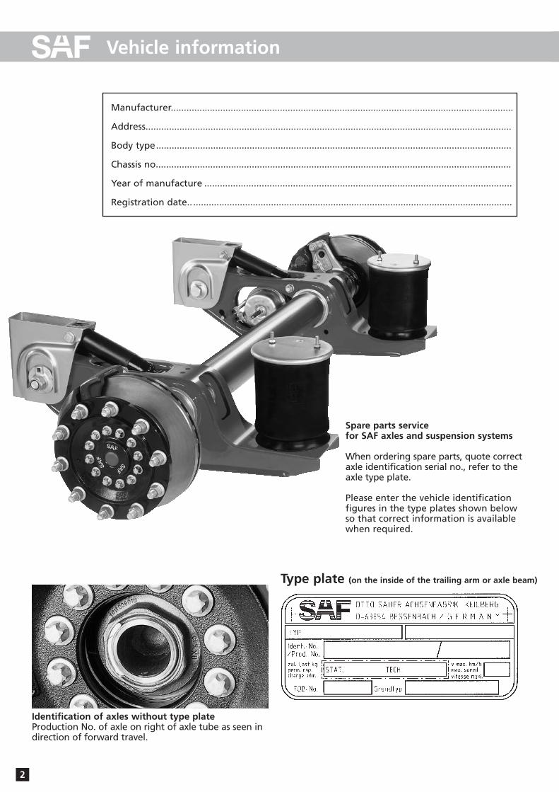
Manufacturer....................................................................................................................................
Address.............................................................................................................................................
Body type.........................................................................................................................................
Chassis no.........................................................................................................................................
Year of manufacture ......................................................................................................................
Registration date.. ...........................................................................................................................
Spare parts servicefor SAF axles and suspension systems
When ordering spare parts, quote correctaxle identification serial no., refer to theaxle type plate.
Please enter the vehicle identification figures in the type plates shown below so that correct information is availablewhen required.
2
Vehicle information
Identification of axles without type plateProduction No. of axle on right of axle tube as seen in direction of forward travel.
Type plate (on the inside of the trailing arm or axle beam)

SAF axle identification 2
Notes 4
Repairing the brakes 14-20
Replacing pressure pad and folding bellows 20
Replacing the folding bellows of the pressure pad 21-22
Repairing the brake calliper bearing with “guide and seal kit” 23-25
Installing the brake calliper 26
Replacing the brake cylinder 26
Overview of Hub Unit components 27
D) Installation instructions
B) Maintenance instruction
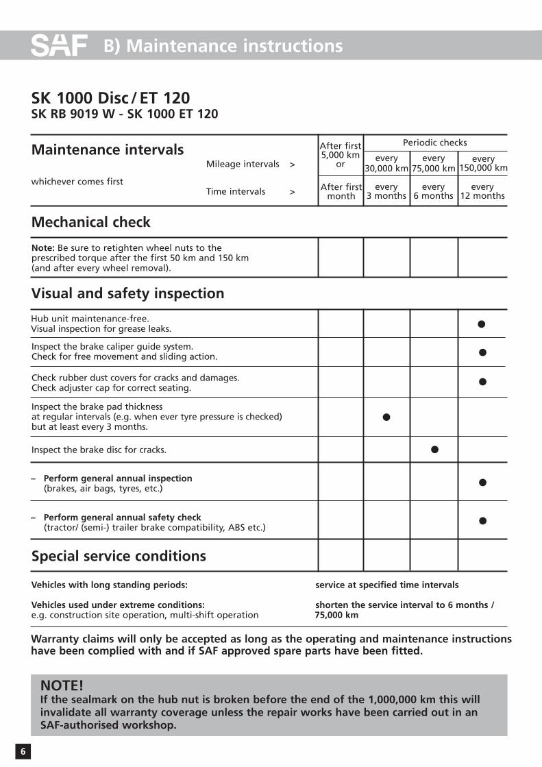
Maintenance instructions for SAF axles SK RB 9019 W - SK 1000 ET 120 6
Maintenance schedule for SAF axles SK RB 9019 W - SK 1000 ET 120 7
Brake testing (fault-finding procedure) 8
Adjuster check 9
Brake pad check 10
Special notes 11
3
Contents
Page
This manual is intended for the technical workshop personnel responsible for maintenan-ce and repair.
A) General safety instructions 5
E) Service tools 28
F) Tightening torque in Nm 29
The item numbers indicated are given only for identification and to distinguish between different versions.
Use the part numbers from the valid spare parts documents for identification of spare parts.
SAF axles and suspension units are subject to continuous further development; the data and drawings contained in the manual may therefore differ from the details given in the operating permit.
The contents of the manual does not constitute the basis for a legal claim.
Reprinting, reproduction or translation in whole or in part is not permitted.
The issue of this publication invalidates all earlier maintenance and repair manuals.
Note: We wish to thank WABCO for providing various illustrations!
Spare part illustration and spare part designation SK RB 9019 W - SK 1000 ET 120 12-13
C) Spare part illustrations/spare part designation

NOTIZEN/NOTES /NOTE
4

A) General safety instructions
Please observe the following safety instructions in order to maintain the operational and road safetyof your SAF axles and suspension systems:
1. The wheel contact surfaces between the wheel disc and wheel hub and the wheel nut contact surfaceat the wheel disc must not be additionally painted. The contact surfaces must be clean, smooth and free from grease. Failure to observe this may result in the wheel coming loose. Any additionalinstructions of the wheel manufacturer must also be observed.
2. Only the wheel and tyre sizes approved by the trailer builder may be used. The tyres must always havethe specified inflation pressure.
3. The brake systems of the tractor and the trailer/semi-trailer must be synchronised by means of a tractor/trailer brake synchronisation not later than 5,000 km after the initial start of operation of thetrailer/semi-trailer in order to ensure a safe and uniform braking behaviour and uniform brake padwear. Tractor/trailer brake synchronisations should be carried out by appropriately qualified and equipped brake workshops.
The use of an additional braking system, such as a trailer anti-jackknife brake is forbidden by law onvehicles with type approval after January 1999.
4. Before starting a journey, ensure that the maximum permissible axle load is not exceeded and that theload is distributed equally and uniformly.
5. On trailers with air suspension, ensure that the air bags are completely filled with air before startingthe journey. Incompletely filled air bags may result in damage to axles, suspension, frame and superstructure and impair road safety.
6. Ensure that the brakes are not overheated by continuous operation.
With drum brakes, overheating can result in a hazardous deterioration in the braking efficiency.
With disc brakes, overheating can result in damage to surrounding components – in particular thewheel bearings. This can result in a significant deterioration in road safety, e.g. failure of wheel bearings.
7. The parking brake must not be immediately applied when the brakes are hot, as the brake discs andbrake drums may be damaged by different stress fields during cooling.
8. Use the supports provided when loading and unloading in order to avoid damage to the axle.
9. Observe the operating recommendation of the trailer builder for off-road operation of the installedaxles and suspension systems.
The SAF definition of OFF-ROAD means driving on non-asphalted / non-concreted routes, such as e.g.gravel roads, agricultural and forestry tracks, on construction sites and in gravel pits.
Off-road operation of SAF axles and suspension systems not designed for the purpose may result indamage and hence to an impairment of road safety.
10. SAF axles and suspension systems require continuous care, service and maintenance in order to maintain operational and road safety and to be able to recognise natural wear and defects in goodtime.
The daily inspection of the trailer for road safety before starting the journey is one of the driver’s obligations.
SAF recommends that at least the inspections and maintenance operations described on page 6 shouldbe carried out.
We recommend the use of original SAF spare parts.A close-knit service network of SAF partner companies is available for the technical support of the SAF axleand suspension systems and for the supply of original SAF spare parts (see rear cover or on the Internetunder www.saf-axles.com).Updates will be published as necessary on the Internet under www.saf-axles.com.
5
6
B) Maintenance instructions
SK 1000 Disc /ET 120SK RB 9019 W - SK 1000 ET 120
Vehicles with long standing periods: service at specified time intervals
Vehicles used under extreme conditions: shorten the service interval to 6 months / e.g. construction site operation, multi-shift operation 75,000 km
Maintenance intervals
whichever comes first
Mileage intervals >
Time intervals >
After first5,000 km
orevery
30,000 kmevery
150,000 km
After firstmonth
every3 months
every75,000 km
every6 months
every12 months
Periodic checks
Hub unit maintenance-free.Visual inspection for grease leaks.
Inspect the brake caliper guide system.Check for free movement and sliding action.
Check rubber dust covers for cracks and damages.Check adjuster cap for correct seating.
Inspect the brake pad thickness at regular intervals (e.g. when ever tyre pressure is checked) but at least every 3 months.
Inspect the brake disc for cracks.
– Perform general annual inspection(brakes, air bags, tyres, etc.)
– Perform general annual safety check(tractor/ (semi-) trailer brake compatibility, ABS etc.)
Note: Be sure to retighten wheel nuts to the prescribed torque after the first 50 km and 150 km (and after every wheel removal).
Mechanical check
Visual and safety inspection
Special service conditions
Warranty claims will only be accepted as long as the operating and maintenance instructionshave been complied with and if SAF approved spare parts have been fitted.
NOTE!If the sealmark on the hub nut is broken before the end of the 1,000,000 km this willinvalidate all warranty coverage unless the repair works have been carried out in an SAF-authorised workshop.
•••
•
•
•
•

7
B) Maintenance instructions
SK 1000 Disc /ET 120SK RB 9019 W - SK 1000 ET 120
Hub unitHub unit maintenance-free.Inspect for signs of wear at each brake disc change (e.g. escape ofgrease).After brake relining, observe the following points:Inspect the seals on the brake calliper.Never use high-pressure cleaners or cleaning fluids on the brakedisc or wheel hub.Clean stub axle of any old grease and apply fresh SAF fitting paste.
Lubricant specifications:
Grease for repairs is contained in every repair kit.
Stub axle:SAF Part No. 4 387 0015 06SAF fitting paste
Tightening the hub nutOn LH side as seen in direction of travel –LH threadOn RH side as seen in direction of travel –RH threadTightening torque 900 Nm. Each hub unit must be rotated smoothly at least twice while tighteningthe bolts.Hub nuts with LH thread are marked:Groove on the face.
Assembly tools SAF Part No.Hub nut wrench 2 012 0023 01Puller for Hub Unit 4 434 3822 00Tool box compl. 3 434 6010 003/4” spanner external torx shape 4 434 3824 00
Thickness of brake disc “A“
Wear limit of brake disc “B“
NOTE!Failure to observe these instructions may result in an accident risk!Worn brake linings or excessively worn brake discs result in areduction in the braking efficiency or in a complete failure of thebrake system.
Thickness of linings “C“
Lining wear “E“ Disc diameter in mm No. of brake pads
per axle
SBW 1937 45 ≤37 30 11 370 4
Brake type
Tightening torque(Nm)
Spanner size(W.A.F.)
Hexagonoutside inside
Guide bearing on brake calliper2 hex. socket head screws 340±20 14 – X
M16 x 1.5 - 10,9
Diaphragm/combination cylinder2 hex. nuts 210 24 X –M16 x 1.5
Brake calliper mountingon axle body 290 24 X –
M16 x 1.5 x 55
Fixing screws of the lining fixing hoop
Item No.
Caution! Bolts must not be oiled!
Wheel flange mountingM18 x 1.5 x 75 or 6544 450 27 X –
TORX screw with headM18 x 1.5 x 75 or 6544
Tightening process: pre-tighten to 50 Nm diagonally,
turning angle of 90º diagonallytightened (1 1/2 nut corners)
External torx E24 – –
30±15 17 X –
56/56.1
63.2

8
B) Maintenance instructions
Brake testing Fault-finding procedure
Lift vehicle, turn wheel
by hand
Does wheel turn freely?
Residual pressure in brake cylinder?
NO YES
NO YES
NO YES
NO YES
NO YES
Check upline brake devices and replace, if necessary
END
NO YES
Running clearence OK?
(see page 19)
Check adjuster(see page 9)
END
Check brake calliper bearings
and repair, if necessary
(see page 18)
END
END
Adjuster OK?(see page 9)
END
Replace brake calliper
(see page 26)
END
Binding not due to disc brake
Brake calliper guide system OK?
(see page 18)
END
Check brake calliper bearings
and repair, if necessary
(see page 18)
Uneven brake pad wear?1)
Disc brake
Running clearence OK?
(see page 19)
NO YES
1) Difference between wear of inboard and outboard pad, and diagonal wear ≤ 2 mm.
9
B) Maintenance instructions
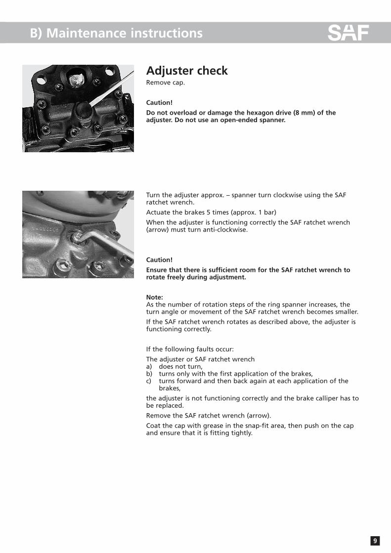
Adjuster checkRemove cap.
Caution!
Do not overload or damage the hexagon drive (8 mm) of the adjuster. Do not use an open-ended spanner.
Turn the adjuster approx. – spanner turn clockwise using the SAFratchet wrench.
Actuate the brakes 5 times (approx. 1 bar)
When the adjuster is functioning correctly the SAF ratchet wrench(arrow) must turn anti-clockwise.
Caution!
Ensure that there is sufficient room for the SAF ratchet wrench torotate freely during adjustment.
Note:As the number of rotation steps of the ring spanner increases, theturn angle or movement of the SAF ratchet wrench becomes smaller.
If the SAF ratchet wrench rotates as described above, the adjuster isfunctioning correctly.
If the following faults occur:
The adjuster or SAF ratchet wrencha) does not turn,b) turns only with the first application of the brakes,c) turns forward and then back again at each application of the
brakes,
the adjuster is not functioning correctly and the brake calliper has tobe replaced.
Remove the SAF ratchet wrench (arrow).
Coat the cap with grease in the snap-fit area, then push on the capand ensure that it is fitting tightly.

B) Maintenance instructions
Brake pad check
Caution!
Observe the wear limits of the brake pads.
Check the thickness of the brake pads for compliance with the legalrequirements at regular intervals, but at least every three months,depending on the operation of the vehicle.
A = Minimum residual lining thickness 2 mmB = Total lining thickness of new pads 21 mm
When the residual lining thickness is A ≤ 2 mm, replace the brakepads.
Signs of wearWear on the middle of the lining can be measured with a tape measure or a ruler either at the shoulder bolt (long bolt near thedisc run in) or at the play bolt (short bolt near the disc run in). Here,the distance between the axle flange and the edge of the housingof each bolt is measured (see illustration). The amount of wear isdetermined to have been reached or exceeded by the following criteria:
Short bolt: wear > 70 mm - replace linings
Long bolt: wear > 97 mm - replace linings
AB
10
B) Maintenance instructions
Special notes
11
Storage instructions
During storage outdoors, ensure that moisture cannot enter the inside of the brake cal-liper through the brake cylinder connection.
Painting instructions
During painting work, all rubber parts must be covered as otherwise the rubber will become brittle and thus be damaged.
Only brake cylinders approved by the brake
or axle manufacturer may by used
12
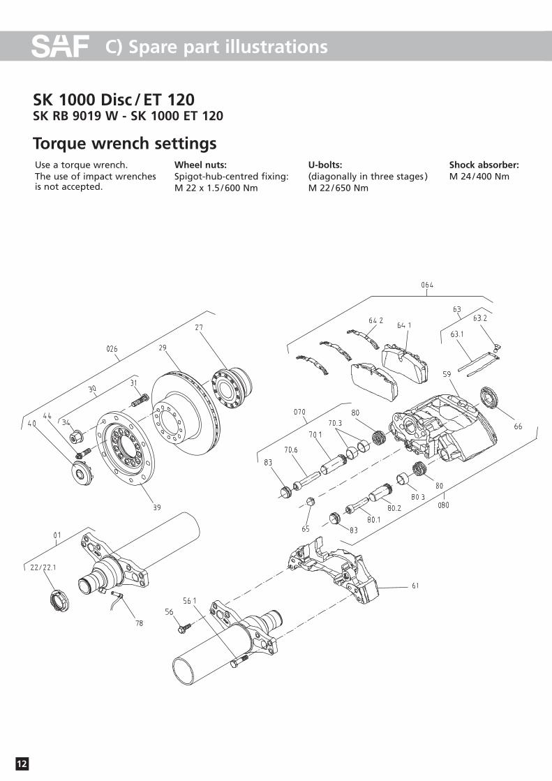
C) Spare part illustrations
SK 1000 Disc /ET 120SK RB 9019 W - SK 1000 ET 120
Torque wrench settingsUse a torque wrench.The use of impact wrenches is not accepted.
Wheel nuts:Spigot-hub-centred fixing:M 22 x 1.5 /600 Nm
U-bolts:(diagonally in three stages )M 22 /650 Nm
Shock absorber:M 24 /400 Nm
13
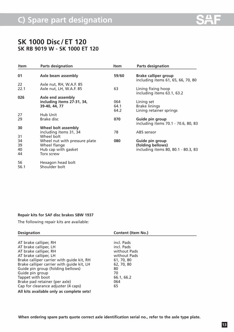
C) Spare part designation
SK 1000 Disc /ET 120SK RB 9019 W - SK 1000 ET 120
Item Parts designation Item Parts designation
01 Axle beam assembly
22 Axle nut, RH, W.A.F. 8522.1 Axle nut, LH, W.A.F. 85
026 Axle end assemblyincluding items 27-31, 34, 39-40, 44, 77
27 Hub Unit29 Brake disc
30 Wheel bolt assemblyincluding items 31, 34
31 Wheel bolt34 Wheel nut with pressure plate39 Wheel flange40 Hub cap with gasket44 Torx screw
56 Hexagon head bolt 56.1 Shoulder bolt
59/60 Brake calliper groupincluding items 61, 65, 66, 70, 80
63 Lining fixing hoopincluding items 63.1, 63.2
064 Lining set64.1 Brake linings64.2 Lining retainer springs
070 Guide pin groupincluding items 70.1 - 70.6, 80, 83
78 ABS sensor
080 Guide pin group(folding bellows)including items 80, 80.1 - 80.3, 83
Repair kits for SAF disc brakes SBW 1937
The following repair kits are available:
Designation Content (Item No.)
AT brake calliper, RH incl. PadsAT brake calliper, LH incl. PadsAT brake calliper, RH without PadsAT brake calliper, LH without PadsBrake calliper carrier with guide kit, RH 61, 70, 80Brake calliper carrier with guide kit, LH 62, 70, 80Guide pin group (folding bellows) 80Guide pin group 70Tappet with boot 66.1, 66.2Brake pad retainer (per axle) 064Cap for clearance adjuster (4 caps) 65All kits available only as complete sets!
When ordering spare parts quote correct axle identification serial no., refer to the axle type plate.

14
D) Installation instructions
Repairing the brakes
Remove the brake calliper.
Park the vehicle on level, solid ground and chock the wheels to prevent the vehicle from rolling away.
Lift the axle using a jack.
Loosen the wheel nuts and remove the wheel.
Remove the cap.
Return adjuster clockwise –turn until the stop.
Loosen and remove thefixing screws of the liningretainer hoop.
Move the brake callipertowards the rim and removelinings
Move brake calliper towardsthe inside, remove liningsand pressure plate.
Unbolt the spring pressure ordiaphragm cylinder from thebrake calliper. Then loosenbolts (6 bolts M 16 x 1.5) andremove the brake calliper.

15
D) Installation instructions
Check the brake calliper for free and easy movement.
Back off the tappets on the adjuster until the boots are visible.
Perform a visual inspection of the boots and all seals.
Screw in the tappets again completely.
Replacing the brake discUnscrew bolts M 18 x 1.5 from the wheel flange and remove thewheel flange.
Note:Bolts must not be oiled!
(Observe tightening torques)
Press the brake disc off the hub unit with 3 hexagon head bolts M 12 x 30.
Clean contact surfaces before assembly.
Caution!
Seal on axle nut must not be damaged as this would invalidate allwarranty claims.

16
D) Installation instructions
Brake discBrake disc diameter
Permissible wear, see table in chapter “Maintenance instructions”.
The brake disc may only be cleaned using a dry cleaning agent.
Inspecting the brake discInspect the braking surface of the brake disc carefully for serviceability.
A1 – Network-like cracks are permissible.
B1 – Cracks up to max. 1.5 mm (width and depth) running towardsthe middle of the hub are permissible.
C1 – Unevenness in the disc surface up to 1.5 mm is permissible.
D1 – Cracks going right through the disc are not permissible.
Check the brake disc thickness and turn down, if necessary. Forsafety reasons, the minimum thickness for turning down the brakediscs is 39 - 40 mm.
Permissible wear, see table in chapter “Maintenance instructions”.
Note:The compact wheel bearing unit and the brake calliper are not remo-ved for turning down the brake disc.
Replacing the hub unitLoosen axle nut and unscrew from stub shaft.
Axle nut wrench, SAF Part No. 2 012 0023 01.
Note:Axle nut W.A.F. 85– on left-hand side as seen in direction of forward travel = left-hand thread. The axle nut with left-hand thread has a milled groove on the outerface for identification.
The complete hub unit can be pulled off the stub shaft using a puller, SAF Part No. 4 434 3822 00.
(The hub unit cannot be overhauled and has to be replaced completewith the bolts of the wheel flange).
A1
D1
B1
C1

17
D) Installation instructions
Installing the hub unitEmery the seating surfaces of the hub unit on the stub shaft down to the bare metal and coat with SAF fitting paste (SAF Part No. 4 387 0015 06).
Coat the hub unit bearing surfaces with SAF fitting paste and pushonto the stub shaft. Tighten the axle nut to the prescribed torque.
On LH side as seen in direction of travel – LH threadOn RH side as seen in direction of travel – RH threadTightening torque 900 Nm. Each hub unit must be rotated smoothly at least twice while tightening the bolts. Hub nuts with LH thread are marked:Groove on the face
Axle nut W.A.F. 85:On left-hand side of vehicle (as seen in direction of forward travel) –left-hand thread.
Identification of axle nut with left-hand thread: Milled groove onoutside of hexagonal head.Groove on the face.Tighten the axle nut.Axle nut wrench: SAF Part No. 2 012 0023 01
Tightening torque 900 Nm. Each hub unit must be rotated smoothly at least twice while tightening the bolts.
Special locking of the axle nut is not necessary.
Place the wheel flange onto the hub unit and tighten the new, unoiled bolts to the prescribed torque.
18
D) Installation instructions
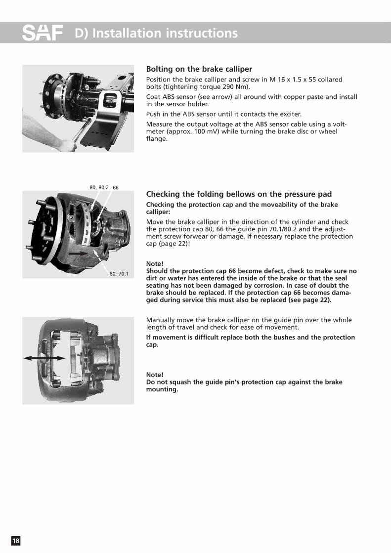
Bolting on the brake calliperPosition the brake calliper and screw in M 16 x 1.5 x 55 collaredbolts (tightening torque 290 Nm).
Coat ABS sensor (see arrow) all around with copper paste and installin the sensor holder.
Push in the ABS sensor until it contacts the exciter.
Measure the output voltage at the ABS sensor cable using a volt-meter (approx. 100 mV) while turning the brake disc or wheel flange.
Checking the folding bellows on the pressure padChecking the protection cap and the moveability of the brake calliper:
Move the brake calliper in the direction of the cylinder and checkthe protection cap 80, 66 the guide pin 70.1/80.2 and the adjust-ment screw forwear or damage. If necessary replace the protectioncap (page 22)!
Note!Should the protection cap 66 become defect, check to make sure nodirt or water has entered the inside of the brake or that the sealseating has not been damaged by corrosion. In case of doubt thebrake should be replaced. If the protection cap 66 becomes dama-ged during service this must also be replaced (see page 22).
Manually move the brake calliper on the guide pin over the wholelength of travel and check for ease of movement.
If movement is difficult replace both the bushes and the protectioncap.
Note!Do not squash the guide pin's protection cap against the brakemounting.
80, 80.2 66
80, 70.1
19
D) Installation instructions
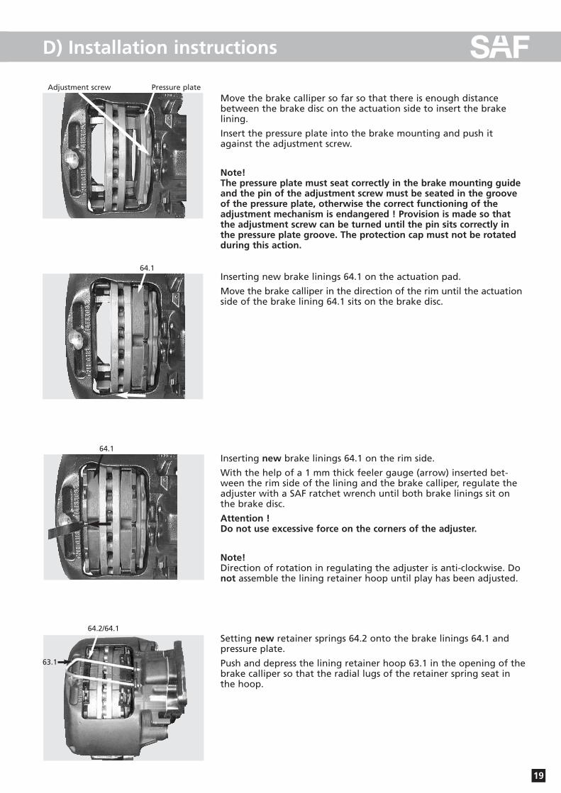
Move the brake calliper so far so that there is enough distance between the brake disc on the actuation side to insert the brakelining.
Insert the pressure plate into the brake mounting and push itagainst the adjustment screw.
Note!The pressure plate must seat correctly in the brake mounting guideand the pin of the adjustment screw must be seated in the grooveof the pressure plate, otherwise the correct functioning of theadjustment mechanism is endangered ! Provision is made so thatthe adjustment screw can be turned until the pin sits correctly inthe pressure plate groove. The protection cap must not be rotatedduring this action.
Inserting new brake linings 64.1 on the actuation pad.
Move the brake calliper in the direction of the rim until the actuationside of the brake lining 64.1 sits on the brake disc.
Inserting new brake linings 64.1 on the rim side.
With the help of a 1 mm thick feeler gauge (arrow) inserted bet-ween the rim side of the lining and the brake calliper, regulate theadjuster with a SAF ratchet wrench until both brake linings sit onthe brake disc.
Attention !Do not use excessive force on the corners of the adjuster.
Note!Direction of rotation in regulating the adjuster is anti-clockwise. Donot assemble the lining retainer hoop until play has been adjusted.
Setting new retainer springs 64.2 onto the brake linings 64.1 andpressure plate.
Push and depress the lining retainer hoop 63.1 in the opening of thebrake calliper so that the radial lugs of the retainer spring seat inthe hoop.
Pressure plateAdjustment screw
64.1
64.1
64.2/64.1
63.1

D) Installation instructions
20
Affixing new hex. screw 63.2 with 30±15 using a spanner onto thebrake calliper.
Push the new plug 65 into the opening of the brake calliper! Checkthe wheel hub for freedom of movement.
Note!Check the brakes on a rolling road test station after completion ofwork.
Fit the wheels.
Tighten the wheel nuts using a torque wrench.
Caution!Tighten the wheel nuts using a torque wrench again after driving 50 km and 150 km!
63.2
65
D) Installation instructions
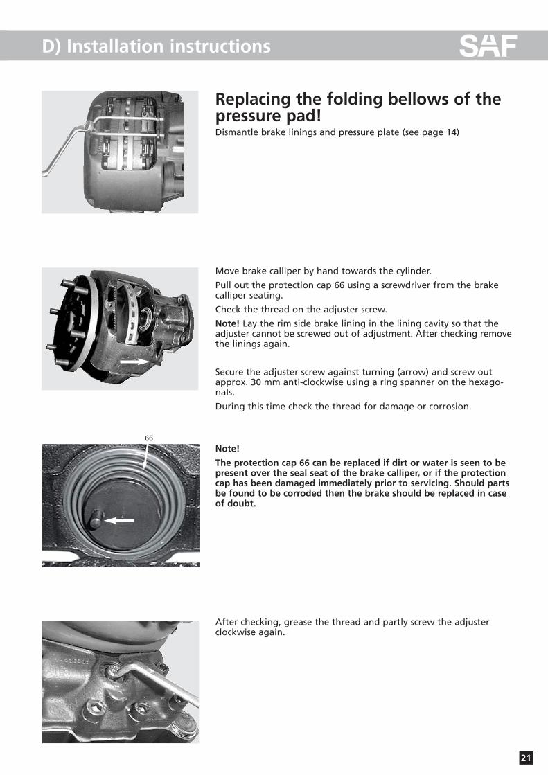
21
Replacing the folding bellows of thepressure pad!Dismantle brake linings and pressure plate (see page 14)
Move brake calliper by hand towards the cylinder.
Pull out the protection cap 66 using a screwdriver from the brakecalliper seating.
Check the thread on the adjuster screw.
Note! Lay the rim side brake lining in the lining cavity so that theadjuster cannot be screwed out of adjustment. After checking removethe linings again.
Secure the adjuster screw against turning (arrow) and screw outapprox. 30 mm anti-clockwise using a ring spanner on the hexago-nals.
During this time check the thread for damage or corrosion.
Note!
The protection cap 66 can be replaced if dirt or water is seen to bepresent over the seal seat of the brake calliper, or if the protectioncap has been damaged immediately prior to servicing. Should partsbe found to be corroded then the brake should be replaced in caseof doubt.
After checking, grease the thread and partly screw the adjusterclockwise again.
66
22
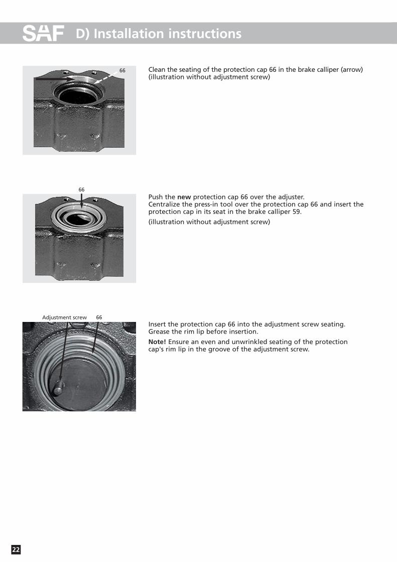
D) Installation instructions
Clean the seating of the protection cap 66 in the brake calliper (arrow) (illustration without adjustment screw)
Push the new protection cap 66 over the adjuster.Centralize the press-in tool over the protection cap 66 and insert theprotection cap in its seat in the brake calliper 59.
(illustration without adjustment screw)
Insert the protection cap 66 into the adjustment screw seating.Grease the rim lip before insertion.
Note! Ensure an even and unwrinkled seating of the protectioncap's rim lip in the groove of the adjustment screw.
66
66
Adjustment screw 66

23
D) Installation instructions
Repairing the brake calliper bearingwith “guide and seal kit”Dismantle the brake calliper 59 from the brake mounting 61 andadditionally remove the cap 83 of the guide pin 70.1/80.2 with a screwdriver from the housing 59.
Note!Do not damage the holes for the cap in the housing.
Loosen the screws 70.6/80.1 with a spanner. Remove the brake calliper 59 from the brake mounting 61.
Note!Danger of trapping through loose brake calliper!
Clean contact surface (flush) on the brake mounting 61 to the guide pin.
Remove the guide pin 70.1/80.2 from the brake calliper 59, removethe protection cap 80 from the groove.
Lay the brake calliper 59 on a firm surface so that the cover openingof the brake calliper is uppermost in order to press out the bushes70.3/80.3
61
59
83,70.1
83,80.2
F F
70.6 80.1
59
61
59
8070.1/80.2
59
70.3/80.3
59
70.3/80.3

24
D) Installation instructions
Press out the bushes 70.3/80.3 from the brake calliper using a pressand mandrel.
Clean the holes in the brake calliper.
.
Press in a new bush 80.3 for the shorter guide pin 80.2.
Press in bush (C) with mandrel (L3 = 38.7 ± 0.2 mm) until it meetsthe stop.
Grease sliding surfaces of the bush.
Insert the new protection cap 80 in the seat (arrow) of the brake calliper (59).
Note! Clean seating before insertion. For ease of insertion of theprotection cap it is recommended to lightly grease the rim lip.
Note! Ensure an even and unwrinkled seating of the protectioncap's rim lip in the groove of the brake calliper.
F
70.3/80.3
59
Press in two new bushes 70.3and for the longer guide pin70.1:
Firstly (A) the inner bush withmandrel (L1 = 52.2 ± 0.2 mm),and finally (B) the outer bushwith a mandrel (L2 = 13.2 ± 0.2 mm), in bothcases press in until they meetthe stop.
Grease sliding surfaces of thebushes and the space betweenthem.
F F
A B
L1
L2 ››
F
L3
C
80
59
70.3/80.3
25
D) Installation instructions
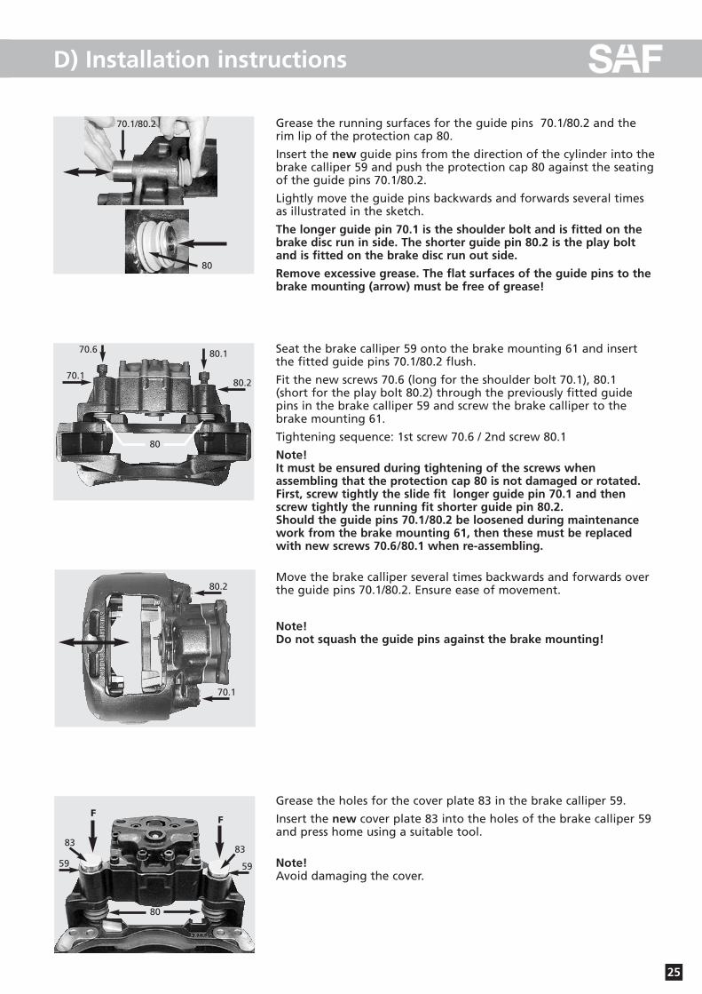
Grease the running surfaces for the guide pins 70.1/80.2 and therim lip of the protection cap 80.
Insert the new guide pins from the direction of the cylinder into thebrake calliper 59 and push the protection cap 80 against the seatingof the guide pins 70.1/80.2.
Lightly move the guide pins backwards and forwards several timesas illustrated in the sketch.
The longer guide pin 70.1 is the shoulder bolt and is fitted on thebrake disc run in side. The shorter guide pin 80.2 is the play boltand is fitted on the brake disc run out side.
Remove excessive grease. The flat surfaces of the guide pins to thebrake mounting (arrow) must be free of grease!
Seat the brake calliper 59 onto the brake mounting 61 and insertthe fitted guide pins 70.1/80.2 flush.
Fit the new screws 70.6 (long for the shoulder bolt 70.1), 80.1 (short for the play bolt 80.2) through the previously fitted guidepins in the brake calliper 59 and screw the brake calliper to thebrake mounting 61.
Tightening sequence: 1st screw 70.6 / 2nd screw 80.1
Note!It must be ensured during tightening of the screws when assembling that the protection cap 80 is not damaged or rotated.First, screw tightly the slide fit longer guide pin 70.1 and thenscrew tightly the running fit shorter guide pin 80.2. Should the guide pins 70.1/80.2 be loosened during maintenancework from the brake mounting 61, then these must be replacedwith new screws 70.6/80.1 when re-assembling.
Move the brake calliper several times backwards and forwards overthe guide pins 70.1/80.2. Ensure ease of movement.
Note!Do not squash the guide pins against the brake mounting!
Grease the holes for the cover plate 83 in the brake calliper 59.
Insert the new cover plate 83 into the holes of the brake calliper 59and press home using a suitable tool.
Note!Avoid damaging the cover.
70.1/80.2
80
80.170.6
70.180.2
80
80.2
70.1
FF
8383
59 59
80
26
D) Installation instructions
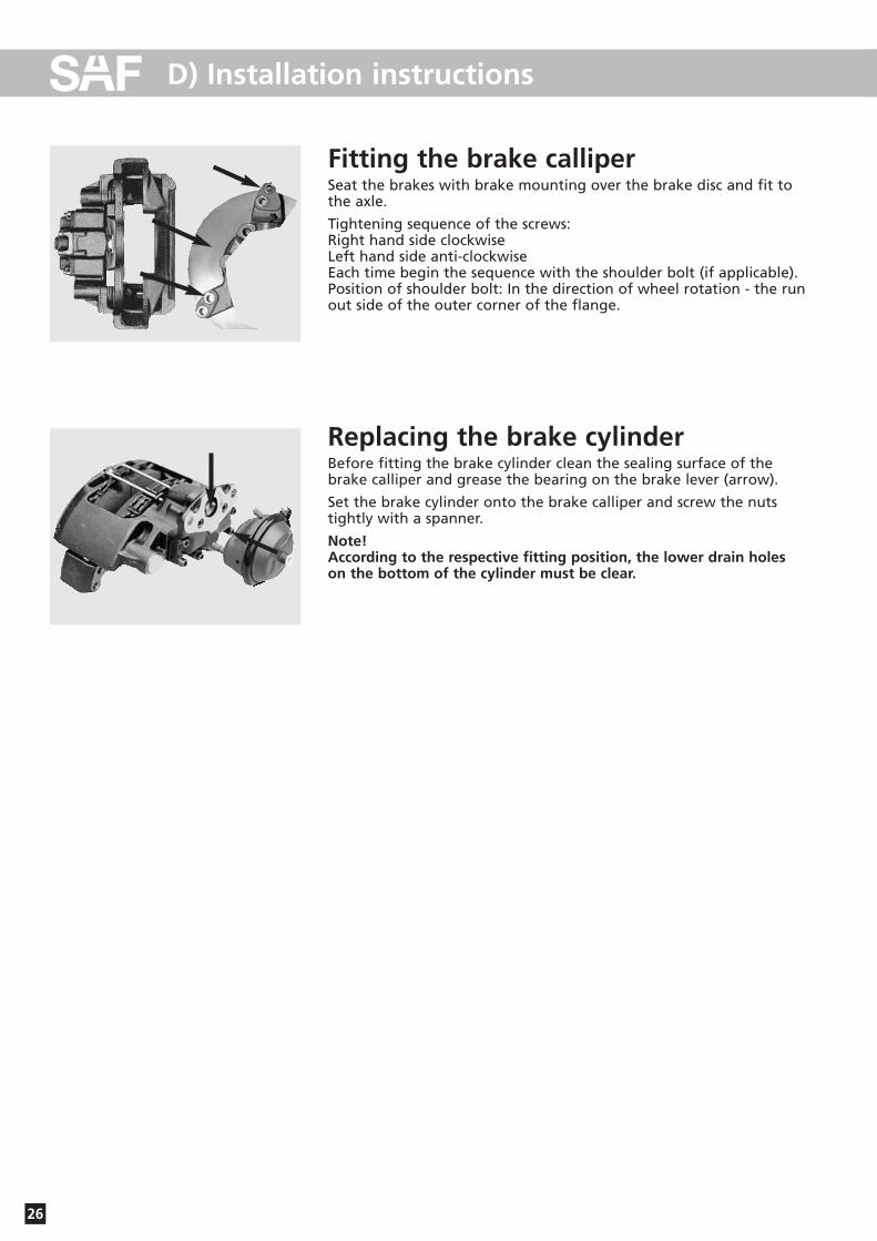
Fitting the brake calliperSeat the brakes with brake mounting over the brake disc and fit tothe axle.
Tightening sequence of the screws:Right hand side clockwiseLeft hand side anti-clockwiseEach time begin the sequence with the shoulder bolt (if applicable).Position of shoulder bolt: In the direction of wheel rotation - the runout side of the outer corner of the flange.
Replacing the brake cylinderBefore fitting the brake cylinder clean the sealing surface of thebrake calliper and grease the bearing on the brake lever (arrow).
Set the brake cylinder onto the brake calliper and screw the nutstightly with a spanner.
Note!According to the respective fitting position, the lower drain holeson the bottom of the cylinder must be clear.

27
D) Installation instructions
Overview of HubUnit components
Hub cap Axle nut, RH / LH thread
Wheel flange Brake disc
Brake calliper
Hub Unit Hub Unit

28
E) Service tools
1. Axle nut wrench WAF 85SAF Part No. 2 012 0023 01
2. Wheel hub pullerSAF Part No. 4 434 3822 00
3. WABCO tool boxSAF Part No. 3 434 6010 00
4. SAF ratchet wrenchSAF Part No. 3 434 3327 00

29
F) Bolt / Nut torque values
M 8 W.A.F. 13 25 35 41
M 8 x 1 27 38 45
M 10 W.A.F. 17 / 16 49 69 83
M 10 x 1 52 73 88
M 12 W.A.F. 19 / 18 86 120 145
M 12 x 15 90 125 150
M 14 W.A.F. 22 / 21 135 190 230
M 14 x 1.5 150 210 250
M 16 W.A.F. 24 210 300 355
M 16 x 1.5 225 315 380
M 18 W.A.F. 27 300 405 485
M 18 x 1.5 325 460 550
M 20 W.A.F. 30 410 580 690
M 20 x 1.5 460 640 770
M 22 W.A.F. 32 550 780 930
M 22 x 1.5 610 860 1050
M 24 W.A.F. 36 710 1000 1200
M 24 x 2 780 1100 1300
M 27 W.A.F. 41 1050 1500 1800
M 27 x 2 1150 1600 1950
M 30 W.A.F. 46 1450 2000 2400
M 30 x 2 1600 2250 2700
M 36 x 2 W.A.F. 55 2450 3450 4150
Wheel fixing:Wheels see appropriate axle maintenance chart.
TRILEX wheels M 18 270 - 300 NmM 20 320 - 350 Nm
The following tightening torques are only valid if no other values are given in the axle maintenance chart.
Torque wrenches settings, impact wrench not permissible.
Thread Material8,8 10,9 12,9W.A.F.

SV11
199G
B E
ditio
n 01
/200
6 ·L
ast u
pdat
ed 2
006-
01-3
1 · A
men
dmen
ts a
nd e
rrors
rese
rved
© S
AF
NonStopService 24Soforthilfe im Pannenfall
Support in the case of service
Otto Sauer Achsenfabrik GmbH · Hauptstraße 26 · D-63856 Bessenbach Tel +49 (0) 60 95 / 301-0 · Fax +49 (0) 60 95 / 301-259 · www.saf-axles.com
· Im Servicefall wählen Sie bitte immer die Rufnummer Ihres Heimatlandes.
· In the case of service please always dial the number of your own country.
+43 3 62 27 23 21+32 59 33 07 07
+30 21 09 40 19 80+386 26 16 58 35+41 19 08 64 90
+42 02 61 10 45 0600800 72 37 37 84 / +49 73 33 80 81 58
+45 75 72 74 74+34 9 13 82 68 41
+372 697 91 96+3 33 88 72 06 43+35 8 93 51 31 33
+41 19 08 64 90+44 87 02 42 02 37+30 21 09 40 19 80
+36 13 45 17 27+386 26 16 58 35
+39 02 66 16 55 74+44 87 02 42 02 37
+32 59 33 07 07+372 697 91 96+372 697 91 96
+33 3 88 72 06 43+386 26 16 58 35+45 75 72 74 74+32 59 33 07 07
+34 9 13 82 68 41+48 6 18 31 98 70+40 2 12 50 02 60
+39 02 66 16 55 74+45 75 72 74 74
+42 02 61 10 45 06+386 26 16 58 35
+90 21 22 75 13 21+386 26 16 58 35
Inlandhome country
03 62 27 23 210 59 33 07 07+30 21 09 40 19 80+386 26 16 58 350 19 08 64 902 61 10 45 060800 72 37 37 84 / 0 73 33 80 81 5875 72 74 749 02 18 19 92697 91 9603 88 72 06 430 93 51 31 33+41 19 08 64 900 87 02 42 02 3721 09 40 19 8006 13 45 17 27+386 26 16 58 3502 66 16 55 74+44 87 02 42 02 37+32 59 33 07 07+372 697 91 96+372 697 91 96+33 3 88 72 06 43+386 26 16 58 35+45 75 72 74 74+32 59 33 07 07+34 9 13 82 68 4106 18 31 98 7002 12 50 02 60+39 02 66 16 55 74+45 75 72 74 74+42 02 61 10 45 060 26 16 58 350 21 22 75 13 21+386 26 16 58 35
Vom Auslandfrom abroad
�A
B
BG
BIH
CH
CZ
D
DK
E
EST
F
FIN
FL
GB
GR
H
HR
I
IRL
L
LT
LV
MC
MK
N
NL
P
PL
RO
RSM
S
SK
SLO
TR
YU
www.saf-axles.com