maintenance and service guide - hewlett packardh20628.safety warning notice warning! to reduce the...
TRANSCRIPT
HP ProBook 4540s Notebook PCHP ProBook 4440s Notebook PCHP ProBook 4441s Notebook PC
Maintenance and Service Guide

© Copyright 2012 Hewlett-PackardDevelopment Company, L.P.
Bluetooth is a trademark owned by itsproprietor and used by Hewlett-PackardCompany under license. Intel and Core aretrademarks or registered trademarks of IntelCorporation in the United States and othercountries. Microsoft and Windows are eithertrademarks or registered trademarks ofMicrosoft Corporation in the United Statesand/or other countries. SD Logo is atrademark of its proprietor.
The information contained herein is subjectto change without notice. The onlywarranties for HP products and services areset forth in the express warranty statementsaccompanying such products and services.Nothing herein should be construed asconstituting an additional warranty. HP shallnot be liable for technical or editorial errorsor omissions contained herein.
First Edition: October 2012
Document Part Number: 702219-001

Safety warning notice
WARNING! To reduce the possibility of heat-related injuries or of overheating the computer, do notplace the computer directly on your lap or obstruct the computer air vents. Use the computer only ona hard, flat surface. Do not allow another hard surface, such as an adjoining optional printer, or a softsurface, such as pillows or rugs or clothing, to block airflow. Also, do not allow the AC adapter tocontact the skin or a soft surface, such as pillows or rugs or clothing, during operation. The computerand the AC adapter comply with the user-accessible surface temperature limits defined by theInternational Standard for Safety of Information Technology Equipment (IEC 60950).
iii

Table of contents
1 Product description ........................................................................................................................................ 1
2 External component identification ................................................................................................................ 9
Display .................................................................................................................................................. 9
Display - SUSE Linux models ............................................................................................................ 11
Top ..................................................................................................................................................... 12
TouchPad .......................................................................................................................... 12
Lights ................................................................................................................................. 13
Buttons, speakers, and fingerprint reader (select models only) ......................................... 14
Keys – Windows models .................................................................................................... 16
Model 4540s ...................................................................................................... 16
Model 4440s/4441s ........................................................................................... 17
Keys - SUSE Linux models ................................................................................................ 18
Front ................................................................................................................................................... 20
Left ..................................................................................................................................................... 21
Right ................................................................................................................................................... 22
Bottom ................................................................................................................................................ 23
3 Illustrated parts catalog ............................................................................................................................... 24
Service tag and PCID label ................................................................................................................ 24
Service tag ......................................................................................................................... 24
PCID label .......................................................................................................................... 25
Computer major components ............................................................................................................. 26
Model 4540s ...................................................................................................................... 26
Model 4440s/4441s ........................................................................................................... 30
Display components ........................................................................................................................... 34
Plastics Kit .......................................................................................................................................... 35
Cable Kit ............................................................................................................................................. 36
Mass storage devices ......................................................................................................................... 37
Miscellaneous parts ............................................................................................................................ 38
Sequential part number listing ............................................................................................................ 39
v
4 Removal and replacement procedures ....................................................................................................... 46
Preliminary replacement requirements ............................................................................................... 46
Tools required .................................................................................................................... 46
Service considerations ....................................................................................................... 46
Plastic parts ....................................................................................................... 46
Cables and connectors ..................................................................................... 47
Drive handling ................................................................................................... 47
Grounding guidelines ......................................................................................................... 48
Electrostatic discharge damage ........................................................................ 48
Packaging and transporting guidelines ............................................. 49
Workstation guidelines ..................................................................... 49
Equipment guidelines ....................................................................... 50
Component replacement procedures ................................................................................................. 51
Battery ............................................................................................................................... 52
Using the optional security screw ...................................................................................... 53
Bottom door ....................................................................................................................... 54
SIM .................................................................................................................................... 55
Optical drive ....................................................................................................................... 56
Hard drive .......................................................................................................................... 58
Memory modules ............................................................................................................... 60
WWAN module .................................................................................................................. 62
WLAN/Bluetooth combo card ............................................................................................ 64
Keyboard ........................................................................................................................... 66
Heat shield ......................................................................................................................... 69
Fan ..................................................................................................................................... 71
Heat sink ............................................................................................................................ 73
Processor ........................................................................................................................... 76
Top cover ........................................................................................................................... 78
Fingerprint reader board .................................................................................................... 85
Speaker assembly ............................................................................................................. 87
Function board/Power button board assembly .................................................................. 89
Audio board ....................................................................................................................... 91
USB connector assembly .................................................................................................. 92
Battery cable ...................................................................................................................... 94
System board ..................................................................................................................... 95
RTC battery ....................................................................................................................... 98
Optical drive extension board (4540s models only) ......................................................... 100
Hard drive extension board (4540s models only) ............................................................ 102
Power cable ..................................................................................................................... 104
Latch assembly ................................................................................................................ 105
Display assembly ............................................................................................................. 107
vi
5 Computer Setup (BIOS) and Advanced System Diagnostics ................................................................. 115
Windows 7 – Computer Setup (BIOS) and Advanced System Diagnostics ..................................... 115
Using Computer Setup .................................................................................................... 115
Starting Computer Setup ................................................................................. 115
Navigating and selecting in Computer Setup .................................................. 115
Restoring factory settings in Computer Setup ................................................. 116
Updating the BIOS .......................................................................................... 117
Downloading SoftPaqs to update the BIOS .................................... 117
BIOS management using system diagnostics ................................ 117
Using f10 setup to update the BIOS ............................................... 117
Determining the BIOS version ........................................................ 118
Downloading a BIOS update .......................................................... 119
BIOS Setup Menu ........................................................................................... 119
Main menu ...................................................................................... 120
Security menu ................................................................................. 120
Diagnostics menu ........................................................................... 120
Using Advanced System Diagnostics .............................................................................. 120
Windows 8 – Computer Setup (BIOS) and Advanced System Diagnostics ..................................... 121
Using Computer Setup .................................................................................................... 121
Starting Computer Setup ................................................................................. 121
Navigating and selecting in Computer Setup .................................................. 121
Restoring factory settings in Computer Setup ................................................. 122
Updating the BIOS .......................................................................................... 123
Determining the BIOS version ........................................................ 123
Downloading a BIOS update .......................................................... 123
Using Advanced System Diagnostics .............................................................................. 124
SUSE Linux – Computer Setup (BIOS) and Advanced System Diagnostics ................................... 125
Starting Computer Setup ................................................................................................. 125
Using Computer Setup .................................................................................................... 125
Navigating and selecting in Computer Setup .................................................. 125
Restoring factory settings in Computer Setup ................................................. 126
Updating the BIOS ........................................................................................................... 126
Determining the BIOS version ......................................................................... 127
Downloading a BIOS update ........................................................................... 127
Using Advanced System Diagnostics .............................................................................. 128
6 Specifications .............................................................................................................................................. 129
Computer specifications ................................................................................................................... 129
39.6-cm (15.6-in), HD display specifications .................................................................................... 130
35.6-cm (14.0-in), HD display specifications .................................................................................... 131
Hard drive specifications .................................................................................................................. 132
vii
DVD±RW and CD-RW SuperMulti DL Combo Drive specifications ................................................. 133
Blu-ray Disc ROM with SuperMulti DVD±R/RW DL Drive ................................................................ 134
Specification information in Device Manager ................................................................................... 135
7 Backup and recovery .................................................................................................................................. 136
Windows 7 – Backup and recovery .................................................................................................. 136
Creating recovery media with HP Recovery Disc Creator ............................................... 137
Creating recovery media ................................................................................. 137
Backing up your information ............................................................................................ 137
Performing a system recovery ......................................................................................... 138
Using the Windows recovery tools .................................................................. 138
Using f11 recovery tools .................................................................................. 139
Using a Windows 7 operating system DVD (purchased separately) ............... 140
Windows 8 – Backup and recovery .................................................................................................. 140
Backing up your information ............................................................................................ 141
Performing a system recovery ......................................................................................... 141
Using the Windows recovery tools .................................................................. 142
Using f11 recovery tools .................................................................................. 142
Using Windows 8 operating system media (purchased separately) ............... 143
Using Windows Refresh for quick and easy recovery ..................................... 144
Remove everything and reinstall Windows ..................................................... 144
Using HP Software Setup ............................................................................... 145
SUSE Linux – Backup and recovery ................................................................................................ 145
Creating backups ............................................................................................................. 145
Backing up your information ............................................................................................ 145
Performing a system recovery ......................................................................................... 146
USB Recovery option (select models only) ..................................................................... 147
Remove everything and reinstall SLED ........................................................................... 148
8 Power cord set requirements .................................................................................................................... 149
Requirements for all countries and regions ...................................................................................... 149
Requirements for specific countries and regions ............................................................................. 150
9 Recycling ..................................................................................................................................................... 152
Battery .............................................................................................................................................. 152
Display .............................................................................................................................................. 152
Index ................................................................................................................................................................. 158
viii
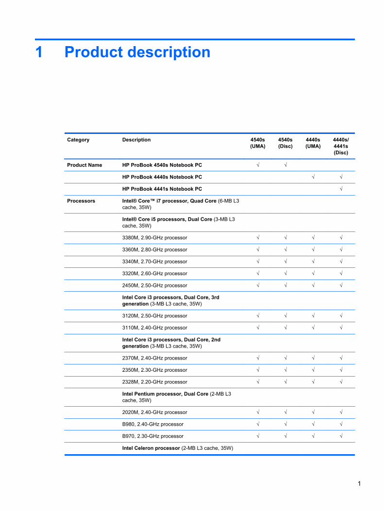
1 Product description
Category Description 4540s(UMA)
4540s(Disc)
4440s(UMA)
4440s/4441s(Disc)
Product Name HP ProBook 4540s Notebook PC √ √
HP ProBook 4440s Notebook PC √ √
HP ProBook 4441s Notebook PC √
Processors Intel® Core™ i7 processor, Quad Core (6-MB L3cache, 35W)
Intel® Core i5 processors, Dual Core (3-MB L3cache, 35W)
3380M, 2.90-GHz processor √ √ √ √
3360M, 2.80-GHz processor √ √ √ √
3340M, 2.70-GHz processor √ √ √ √
3320M, 2.60-GHz processor √ √ √ √
2450M, 2.50-GHz processor √ √ √ √
Intel Core i3 processors, Dual Core, 3rdgeneration (3-MB L3 cache, 35W)
3120M, 2.50-GHz processor √ √ √ √
3110M, 2.40-GHz processor √ √ √ √
Intel Core i3 processors, Dual Core, 2ndgeneration (3-MB L3 cache, 35W)
2370M, 2.40-GHz processor √ √ √ √
2350M, 2.30-GHz processor √ √ √ √
2328M, 2.20-GHz processor √ √ √ √
Intel Pentium processor, Dual Core (2-MB L3cache, 35W)
2020M, 2.40-GHz processor √ √ √ √
B980, 2.40-GHz processor √ √ √ √
B970, 2.30-GHz processor √ √ √ √
Intel Celeron processor (2-MB L3 cache, 35W)
1
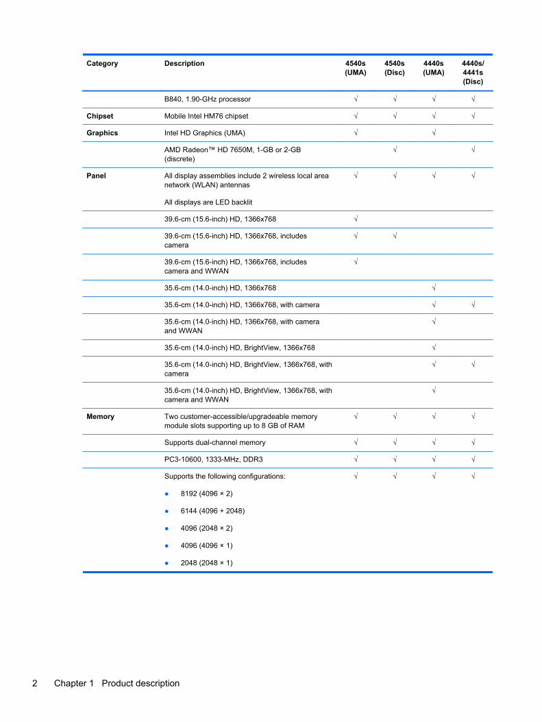
Category Description 4540s(UMA)
4540s(Disc)
4440s(UMA)
4440s/4441s(Disc)
B840, 1.90-GHz processor √ √ √ √
Chipset Mobile Intel HM76 chipset √ √ √ √
Graphics Intel HD Graphics (UMA) √ √
AMD Radeon™ HD 7650M, 1-GB or 2-GB(discrete)
√ √
Panel All display assemblies include 2 wireless local areanetwork (WLAN) antennas
All displays are LED backlit
√ √ √ √
39.6-cm (15.6-inch) HD, 1366x768 √
39.6-cm (15.6-inch) HD, 1366x768, includescamera
√ √
39.6-cm (15.6-inch) HD, 1366x768, includescamera and WWAN
√
35.6-cm (14.0-inch) HD, 1366x768 √
35.6-cm (14.0-inch) HD, 1366x768, with camera √ √
35.6-cm (14.0-inch) HD, 1366x768, with cameraand WWAN
√
35.6-cm (14.0-inch) HD, BrightView, 1366x768 √
35.6-cm (14.0-inch) HD, BrightView, 1366x768, withcamera
√ √
35.6-cm (14.0-inch) HD, BrightView, 1366x768, withcamera and WWAN
√
Memory Two customer-accessible/upgradeable memorymodule slots supporting up to 8 GB of RAM
√ √ √ √
Supports dual-channel memory √ √ √ √
PC3-10600, 1333-MHz, DDR3 √ √ √ √
Supports the following configurations:
● 8192 (4096 × 2)
● 6144 (4096 + 2048)
● 4096 (2048 × 2)
● 4096 (4096 × 1)
● 2048 (2048 × 1)
√ √ √ √
2 Chapter 1 Product description

Category Description 4540s(UMA)
4540s(Disc)
4440s(UMA)
4440s/4441s(Disc)
Brazil
● 8192 (4096 × 2; dual channel)
● 4096 (2048 × 2; dual channel)
● 4096 (4096 × 1)
● 2048 (2048 × 1)
√
Hard drives Supports 7-mm/9.5-mm, 2.5-in SATA hard driveswith HP 3D DriveGuard
√ √ √ √
Supports 12.7-mm. 2.5-inch hard drives with HP 3DDriveGuard
√ √
Customer-accessible √ √ √ √
Supports the following drives:
● 750-GB, 7200-rpm or 5400-rpm
● 640-GB, 5400-rpm
● 500-GB, 7200-rpm or 5400-rpm
● 320-GB, 7200-rpm or 5400-rpm
√ √
Supports the following drives:
● 750-GB, 7200-rpm or 5400-rpm
● 640-GB, 5400-rpm
● 500-GB, 7200-rpm
● 320-GB, 7200-rpm
√ √
Fixed optical drives Supports the following 12.7-mm SATA opticaldrives:
● DVD+/-RW SuperMulti DL
● Blu-ray ROM DVD+/-RW SuperMulti DL
√ √ √ √
DVD-ROM drive √ √
Supports no optical drive option √ √ √ √
Audio/Visual Integrated dual-array microphone (webcam modelsonly)
√ √ √ √
Integrated mono (non-webcam models) √ √
Stereo speakers (2) √ √ √ √
Integrated webcam (720p HD) √ √ √ √
Supports no camera option √ √
Headphone and microphone jacks √ √ √ √
IDT 92HD87 √ √ √ √
3

Category Description 4540s(UMA)
4540s(Disc)
4440s(UMA)
4440s/4441s(Disc)
Ethernet Realtek RTL8151FH-CG 10/100/1000 √ √ √ √
S3/S4/S5 wake on LAN (AC mode only) √ √ √ √
Ethernet cable not included √ √ √ √
Wireless Integrated WLAN options by way of wireless module:
Two WLAN antennas built into display assembly √ √ √ √
Supports “no WLAN” option √ √ √ √
Supports the following WLAN formats:
● Atheros 9485GN 802.11b/g/n 1x1 WiFi and3012 Bluetooth 4.0 Combo Adapter
● Broadcom 4313GN 802.11b/g/n 1x1 WiFi and20702 Bluetooth 4.0 Combo Adapter
● Intel Centrino Wireless-N 2230
● Intel Centrino Advanced-N 6235
● Ralink WLAN Ralink Ripple3 RT5390F_802.11b/g/n 1x1 PCIe HMC
● Atheros AR9485 802.11b/g/n 1x1 WiFiAdapter
● Atheros AR9565 802.11bgn 1x1 WiFi + BT4.0combo Adapter
● Ralink RT3290LE 802.11bgn 1x1 Wi-Fi andBluetooth 4.0 Combo Adapter
● Ralink RT5390R 802.11bgn 1x1 Wi-Fi Adapter
√ √ √ √
Integrated WWAN options by way of wireless module:
Two WWAN antennas built into display assembly(world-wide 5 band, configured with panels)
√ √
Subscriber identity module (SIM) security(customer-accessible)
√ √
Supports “no WWAN” option √ √ √ √
Supports the following WWAN modules:
● Sierra MC8355 HSPA/CDMA with GPS
● Ericsson 5321 HSPA+ with GPS
√ √
Integrated personal area network (PAN) options by way of Bluetooth® module:
Bluetooth 4.0 only supported by combo card √ √ √ √
External media card 6-in-1 Digital Media Reader Slot √ √ √ √
Ports Audio-in (stereo microphone) √ √ √ √
Audio-out (stereo headphone) √ √ √ √
4 Chapter 1 Product description
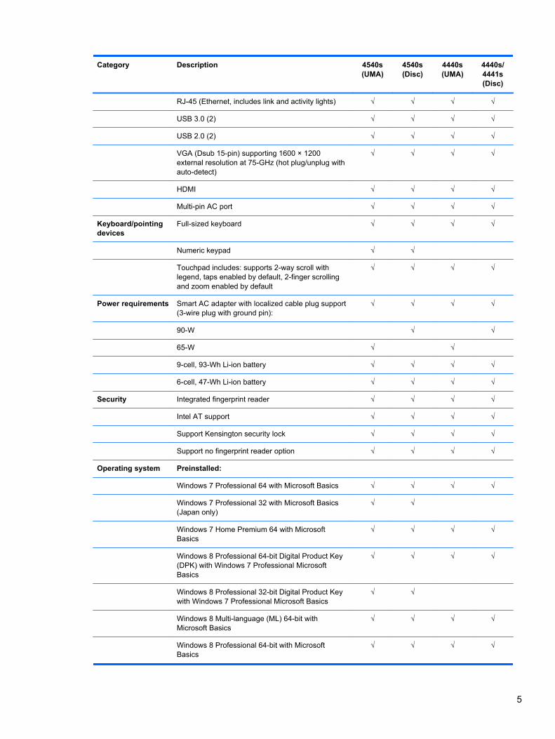
Category Description 4540s(UMA)
4540s(Disc)
4440s(UMA)
4440s/4441s(Disc)
RJ-45 (Ethernet, includes link and activity lights) √ √ √ √
USB 3.0 (2) √ √ √ √
USB 2.0 (2) √ √ √ √
VGA (Dsub 15-pin) supporting 1600 × 1200external resolution at 75-GHz (hot plug/unplug withauto-detect)
√ √ √ √
HDMI √ √ √ √
Multi-pin AC port √ √ √ √
Keyboard/pointingdevices
Full-sized keyboard √ √ √ √
Numeric keypad √ √
Touchpad includes: supports 2-way scroll withlegend, taps enabled by default, 2-finger scrollingand zoom enabled by default
√ √ √ √
Power requirements Smart AC adapter with localized cable plug support(3-wire plug with ground pin):
√ √ √ √
90-W √ √
65-W √ √
9-cell, 93-Wh Li-ion battery √ √ √ √
6-cell, 47-Wh Li-ion battery √ √ √ √
Security Integrated fingerprint reader √ √ √ √
Intel AT support √ √ √ √
Support Kensington security lock √ √ √ √
Support no fingerprint reader option √ √ √ √
Operating system Preinstalled:
Windows 7 Professional 64 with Microsoft Basics √ √ √ √
Windows 7 Professional 32 with Microsoft Basics(Japan only)
√ √
Windows 7 Home Premium 64 with MicrosoftBasics
√ √ √ √
Windows 8 Professional 64-bit Digital Product Key(DPK) with Windows 7 Professional MicrosoftBasics
√ √ √ √
Windows 8 Professional 32-bit Digital Product Keywith Windows 7 Professional Microsoft Basics
√ √
Windows 8 Multi-language (ML) 64-bit withMicrosoft Basics
√ √ √ √
Windows 8 Professional 64-bit with MicrosoftBasics
√ √ √ √
5
Category Description 4540s(UMA)
4540s(Disc)
4440s(UMA)
4440s/4441s(Disc)
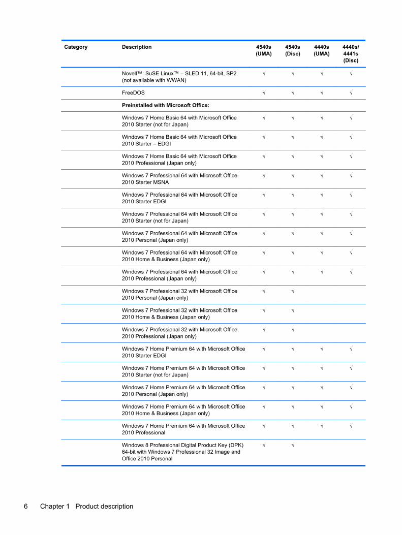
Novell™: SuSE Linux™ – SLED 11, 64-bit, SP2(not available with WWAN)
√ √ √ √
FreeDOS √ √ √ √
Preinstalled with Microsoft Office:
Windows 7 Home Basic 64 with Microsoft Office2010 Starter (not for Japan)
√ √ √ √
Windows 7 Home Basic 64 with Microsoft Office2010 Starter – EDGI
√ √ √ √
Windows 7 Home Basic 64 with Microsoft Office2010 Professional (Japan only)
√ √ √ √
Windows 7 Professional 64 with Microsoft Office2010 Starter MSNA
√ √ √ √
Windows 7 Professional 64 with Microsoft Office2010 Starter EDGI
√ √ √ √
Windows 7 Professional 64 with Microsoft Office2010 Starter (not for Japan)
√ √ √ √
Windows 7 Professional 64 with Microsoft Office2010 Personal (Japan only)
√ √ √ √
Windows 7 Professional 64 with Microsoft Office2010 Home & Business (Japan only)
√ √ √ √
Windows 7 Professional 64 with Microsoft Office2010 Professional (Japan only)
√ √ √ √
Windows 7 Professional 32 with Microsoft Office2010 Personal (Japan only)
√ √
Windows 7 Professional 32 with Microsoft Office2010 Home & Business (Japan only)
√ √
Windows 7 Professional 32 with Microsoft Office2010 Professional (Japan only)
√ √
Windows 7 Home Premium 64 with Microsoft Office2010 Starter EDGI
√ √ √ √
Windows 7 Home Premium 64 with Microsoft Office2010 Starter (not for Japan)
√ √ √ √
Windows 7 Home Premium 64 with Microsoft Office2010 Personal (Japan only)
√ √ √ √
Windows 7 Home Premium 64 with Microsoft Office2010 Home & Business (Japan only)
√ √ √ √
Windows 7 Home Premium 64 with Microsoft Office2010 Professional
√ √ √ √
Windows 8 Professional Digital Product Key (DPK)64-bit with Windows 7 Professional 32 Image andOffice 2010 Personal
√ √
6 Chapter 1 Product description
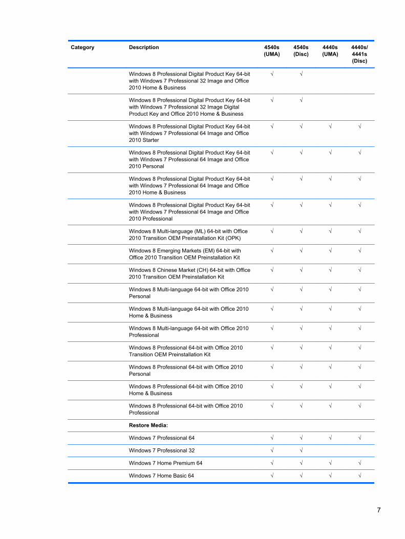
Category Description 4540s(UMA)
4540s(Disc)
4440s(UMA)
4440s/4441s(Disc)
Windows 8 Professional Digital Product Key 64-bitwith Windows 7 Professional 32 Image and Office2010 Home & Business
√ √
Windows 8 Professional Digital Product Key 64-bitwith Windows 7 Professional 32 Image DigitalProduct Key and Office 2010 Home & Business
√ √
Windows 8 Professional Digital Product Key 64-bitwith Windows 7 Professional 64 Image and Office2010 Starter
√ √ √ √
Windows 8 Professional Digital Product Key 64-bitwith Windows 7 Professional 64 Image and Office2010 Personal
√ √ √ √
Windows 8 Professional Digital Product Key 64-bitwith Windows 7 Professional 64 Image and Office2010 Home & Business
√ √ √ √
Windows 8 Professional Digital Product Key 64-bitwith Windows 7 Professional 64 Image and Office2010 Professional
√ √ √ √
Windows 8 Multi-language (ML) 64-bit with Office2010 Transition OEM Preinstallation Kit (OPK)
√ √ √ √
Windows 8 Emerging Markets (EM) 64-bit withOffice 2010 Transition OEM Preinstallation Kit
√ √ √ √
Windows 8 Chinese Market (CH) 64-bit with Office2010 Transition OEM Preinstallation Kit
√ √ √ √
Windows 8 Multi-language 64-bit with Office 2010Personal
√ √ √ √
Windows 8 Multi-language 64-bit with Office 2010Home & Business
√ √ √ √
Windows 8 Multi-language 64-bit with Office 2010Professional
√ √ √ √
Windows 8 Professional 64-bit with Office 2010Transition OEM Preinstallation Kit
√ √ √ √
Windows 8 Professional 64-bit with Office 2010Personal
√ √ √ √
Windows 8 Professional 64-bit with Office 2010Home & Business
√ √ √ √
Windows 8 Professional 64-bit with Office 2010Professional
√ √ √ √
Restore Media:
Windows 7 Professional 64 √ √ √ √
Windows 7 Professional 32 √ √
Windows 7 Home Premium 64 √ √ √ √
Windows 7 Home Basic 64 √ √ √ √
7
Category Description 4540s(UMA)
4540s(Disc)
4440s(UMA)
4440s/4441s(Disc)
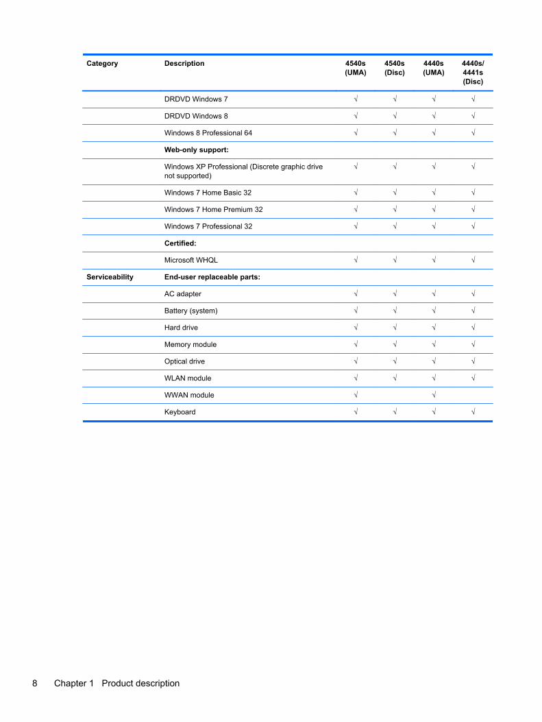
DRDVD Windows 7 √ √ √ √
DRDVD Windows 8 √ √ √ √
Windows 8 Professional 64 √ √ √ √
Web-only support:
Windows XP Professional (Discrete graphic drivenot supported)
√ √ √ √
Windows 7 Home Basic 32 √ √ √ √
Windows 7 Home Premium 32 √ √ √ √
Windows 7 Professional 32 √ √ √ √
Certified:
Microsoft WHQL √ √ √ √
Serviceability End-user replaceable parts:
AC adapter √ √ √ √
Battery (system) √ √ √ √
Hard drive √ √ √ √
Memory module √ √ √ √
Optical drive √ √ √ √
WLAN module √ √ √ √
WWAN module √ √
Keyboard √ √ √ √
8 Chapter 1 Product description
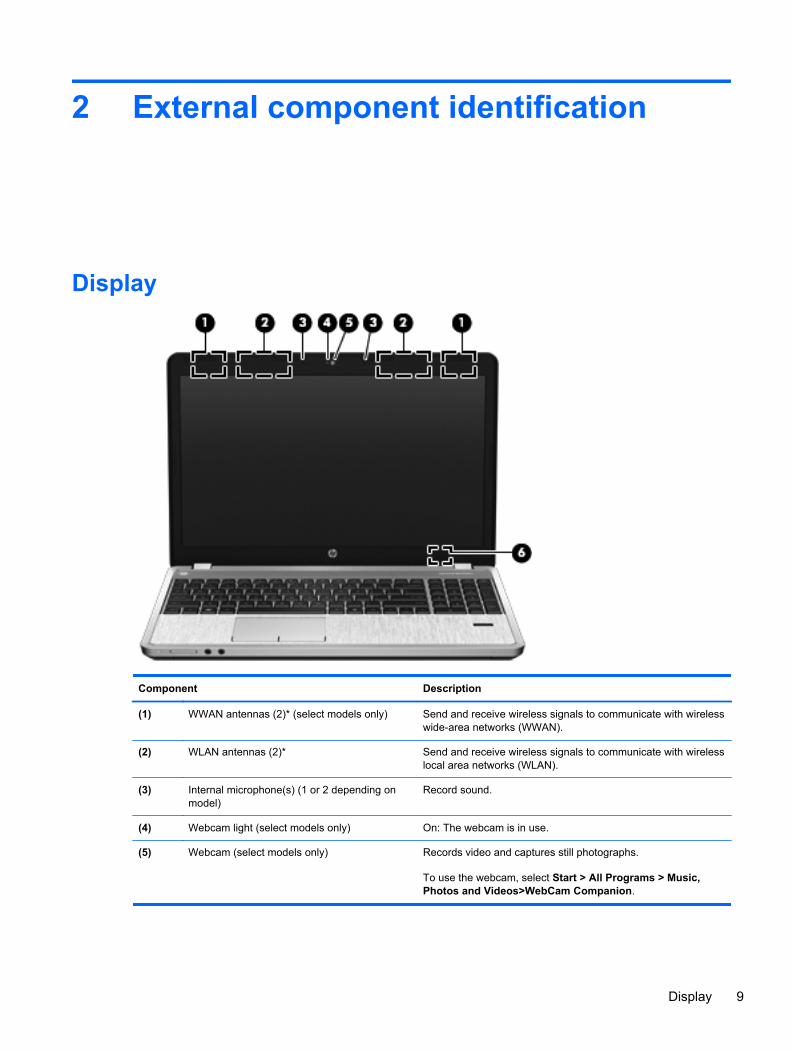
2 External component identification
Display
Component Description
(1) WWAN antennas (2)* (select models only) Send and receive wireless signals to communicate with wirelesswide-area networks (WWAN).
(2) WLAN antennas (2)* Send and receive wireless signals to communicate with wirelesslocal area networks (WLAN).
(3) Internal microphone(s) (1 or 2 depending onmodel)
Record sound.
(4) Webcam light (select models only) On: The webcam is in use.
(5) Webcam (select models only) Records video and captures still photographs.
To use the webcam, select Start > All Programs > Music,Photos and Videos>WebCam Companion.
Display 9
Component Description
(6) Internal display switch Turns off the display or initiates Sleep if the display is closedwhile the power is on.
NOTE: The display switch is not visible from the outside of thecomputer.
*The antennas are not visible from the outside of the computer. For optimal transmission, keep the areas immediatelyaround the antennas free from obstructions. To see wireless regulatory notices, refer to the section of the Regulatory, Safety,and Environmental Notices that applies to your country or region. These notices are located in Help and Support. To accessthis guide in Windows 8, select the HP Support Assistant app on the Start screen, select My computer, and then select theUser guides.
10 Chapter 2 External component identification
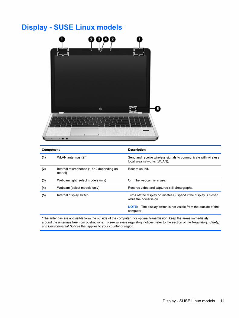
Display - SUSE Linux models
Component Description
(1) WLAN antennas (2)* Send and receive wireless signals to communicate with wirelesslocal area networks (WLAN).
(2) Internal microphones (1 or 2 depending onmodel)
Record sound.
(3) Webcam light (select models only) On: The webcam is in use.
(4) Webcam (select models only) Records video and captures still photographs.
(5) Internal display switch Turns off the display or initiates Suspend if the display is closedwhile the power is on.
NOTE: The display switch is not visible from the outside of thecomputer.
*The antennas are not visible from the outside of the computer. For optimal transmission, keep the areas immediatelyaround the antennas free from obstructions. To see wireless regulatory notices, refer to the section of the Regulatory, Safety,and Environmental Notices that applies to your country or region.
Display - SUSE Linux models 11
Top
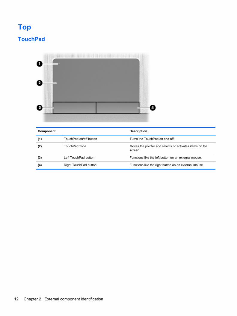
TouchPad
Component Description
(1) TouchPad on/off button Turns the TouchPad on and off.
(2) TouchPad zone Moves the pointer and selects or activates items on thescreen.
(3) Left TouchPad button Functions like the left button on an external mouse.
(4) Right TouchPad button Functions like the right button on an external mouse.
12 Chapter 2 External component identification
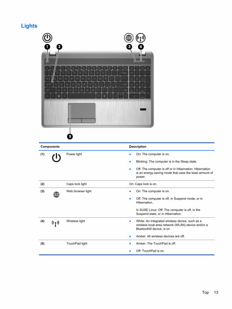
Lights
Components Description
(1) Power light ● On: The computer is on.
● Blinking: The computer is in the Sleep state.
● Off: The computer is off or in Hibernation. Hibernationis an energy-saving mode that uses the least amount ofpower.
(2) Caps lock light On: Caps lock is on.
(3) Web browser light ● On: The computer is on.
● Off: The computer is off, in Suspend mode, or inHibernation.
In SUSE Linux: Off: The computer is off, in theSuspend state, or in Hibernation.
(4) Wireless light ● White: An integrated wireless device, such as awireless local area network (WLAN) device and/or aBluetooth® device, is on
● Amber: All wireless devices are off.
(5) TouchPad light ● Amber: The TouchPad is off.
● Off: TouchPad is on.
Top 13
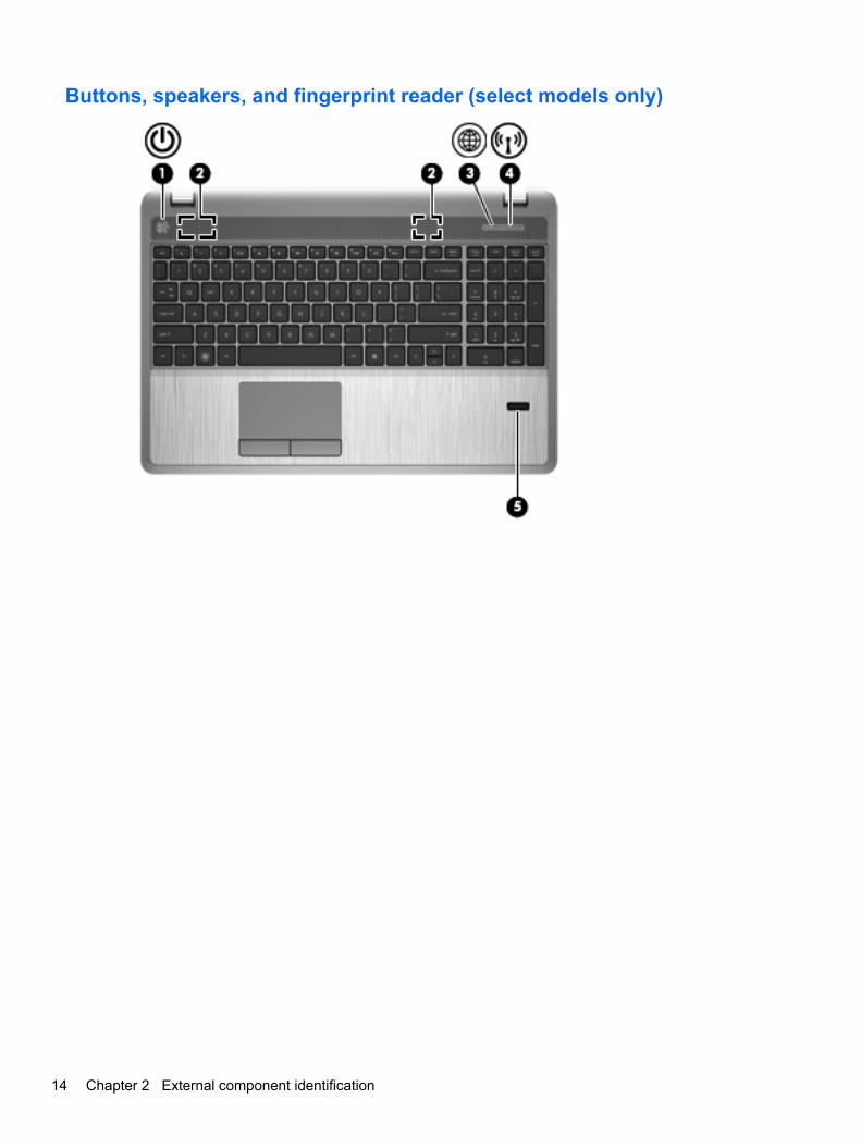
Buttons, speakers, and fingerprint reader (select models only)
14 Chapter 2 External component identification
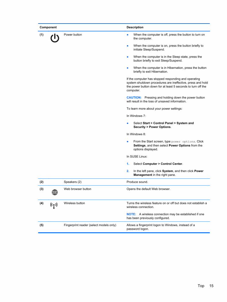
Component Description
(1) Power button ● When the computer is off, press the button to turn onthe computer.
● When the computer is on, press the button briefly toinitiate Sleep/Suspend.
● When the computer is in the Sleep state, press thebutton briefly to exit Sleep/Suspend.
● When the computer is in Hibernation, press the buttonbriefly to exit Hibernation.
If the computer has stopped responding and operatingsystem shutdown procedures are ineffective, press and holdthe power button down for at least 5 seconds to turn off thecomputer.
CAUTION: Pressing and holding down the power buttonwill result in the loss of unsaved information.
To learn more about your power settings:
In Windows 7:
● Select Start > Control Panel > System andSecurity > Power Options.
In Windows 8:
● From the Start screen, type power options. ClickSettings, and then select Power Options from theoptions displayed.
In SUSE Linux:
1. Select Computer > Control Center.
2. In the left pane, click System, and then click PowerManagement in the right pane.
(2) Speakers (2) Produce sound.
(3) Web browser button Opens the default Web browser.
(4) Wireless button Turns the wireless feature on or off but does not establish awireless connection.
NOTE: A wireless connection may be established if onehas been previously configured.
(5) Fingerprint reader (select models only) Allows a fingerprint logon to Windows, instead of apassword logon.
Top 15
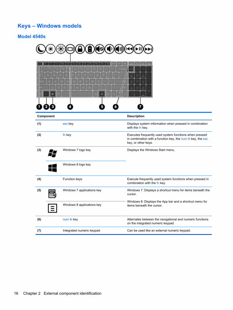
Keys – Windows models
Model 4540s
Component Description
(1) esc key Displays system information when pressed in combinationwith the fn key.
(2) fn key Executes frequently used system functions when pressedin combination with a function key, the num lk key, the esckey, or other keys.
(3) Windows 7 logo key Displays the Windows Start menu.
Windows 8 logo key
(4) Function keys Execute frequently used system functions when pressed incombination with the fn key.
(5) Windows 7 applications key Windows 7: Displays a shortcut menu for items beneath thecursor.
Windows 8: Displays the App bar and a shortcut menu foritems beneath the cursor.Windows 8 applications key
(6) num lk key Alternates between the navigational and numeric functionson the integrated numeric keypad.
(7) Integrated numeric keypad Can be used like an external numeric keypad.
16 Chapter 2 External component identification
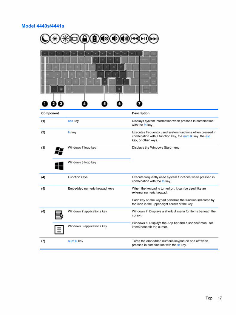
Model 4440s/4441s
Component Description
(1) esc key Displays system information when pressed in combinationwith the fn key.
(2) fn key Executes frequently used system functions when pressed incombination with a function key, the num lk key, the esckey, or other keys.
(3) Windows 7 logo key Displays the Windows Start menu.
Windows 8 logo key
(4) Function keys Execute frequently used system functions when pressed incombination with the fn key.
(5) Embedded numeric keypad keys When the keypad is turned on, it can be used like anexternal numeric keypad.
Each key on the keypad performs the function indicated bythe icon in the upper-right corner of the key.
(6) Windows 7 applications key Windows 7: Displays a shortcut menu for items beneath thecursor.
Windows 8: Displays the App bar and a shortcut menu foritems beneath the cursor.Windows 8 applications key
(7) num lk key Turns the embedded numeric keypad on and off whenpressed in combination with the fn key.
Top 17
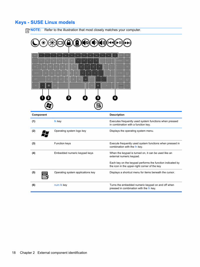
Keys - SUSE Linux models
NOTE: Refer to the illustration that most closely matches your computer.
Component Description
(1) fn key Executes frequently used system functions when pressedin combination with a function key.
(2) Operating system logo key Displays the operating system menu.
(3) Function keys Execute frequently used system functions when pressed incombination with the fn key.
(4) Embedded numeric keypad keys When the keypad is turned on, it can be used like anexternal numeric keypad.
Each key on the keypad performs the function indicated bythe icon in the upper-right corner of the key
(5) Operating system applications key Displays a shortcut menu for items beneath the cursor.
(6) num lk key Turns the embedded numeric keypad on and off whenpressed in combination with the fn key.
18 Chapter 2 External component identification
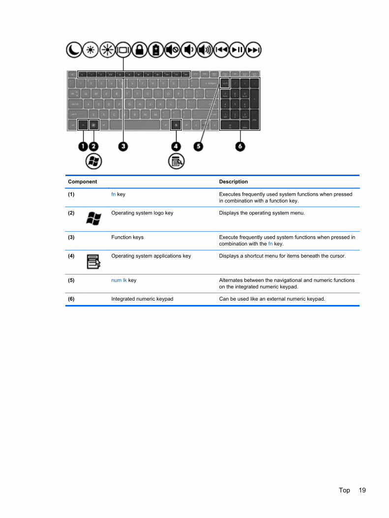
Component Description
(1) fn key Executes frequently used system functions when pressedin combination with a function key.
(2) Operating system logo key Displays the operating system menu.
(3) Function keys Execute frequently used system functions when pressed incombination with the fn key.
(4) Operating system applications key Displays a shortcut menu for items beneath the cursor.
(5) num lk key Alternates between the navigational and numeric functionson the integrated numeric keypad.
(6) Integrated numeric keypad Can be used like an external numeric keypad.
Top 19
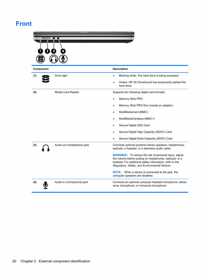
Front
Component Description
(1) Drive light ● Blinking white: The hard drive is being accessed.
● Amber: HP 3D DriveGuard has temporarily parked thehard drive.
(2) Media Card Reader Supports the following digital card formats:
● Memory Stick PRO
● Memory Stick PRO Duo (needs an adapter)
● MultiMediaCard (MMC)
● MultiMediaCardplus (MMC+)
● Secure Digital (SD) Card
● Secure Digital High Capacity (SDHC) Card
● Secure Digital Extra Capacity (SDXC) Card
(3) Audio-out (headphone) jack Connects optional powered stereo speakers, headphones,earbuds, a headset, or a television audio cable.
WARNING! To reduce the risk of personal injury, adjustthe volume before putting on headphones, earbuds, or aheadset. For additional safety information, refer to theRegulatory, Safety, and Environmental Notices
NOTE: When a device is connected to the jack, thecomputer speakers are disabled.
(4) Audio-in (microphone) jack Connects an optional computer headset microphone, stereoarray microphone, or monaural microphone.
20 Chapter 2 External component identification
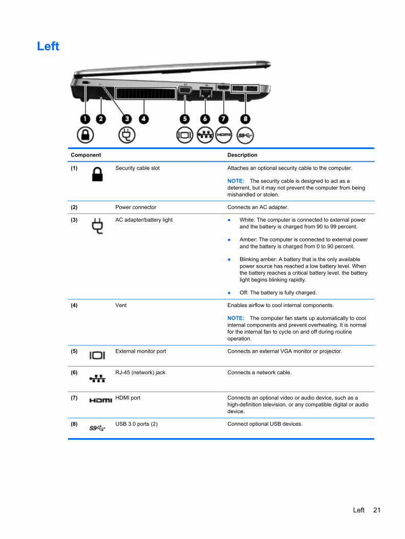
Left
Component Description
(1) Security cable slot Attaches an optional security cable to the computer.
NOTE: The security cable is designed to act as adeterrent, but it may not prevent the computer from beingmishandled or stolen.
(2) Power connector Connects an AC adapter.
(3) AC adapter/battery light ● White: The computer is connected to external powerand the battery is charged from 90 to 99 percent.
● Amber: The computer is connected to external powerand the battery is charged from 0 to 90 percent.
● Blinking amber: A battery that is the only availablepower source has reached a low battery level. Whenthe battery reaches a critical battery level, the batterylight begins blinking rapidly.
● Off: The battery is fully charged.
(4) Vent Enables airflow to cool internal components.
NOTE: The computer fan starts up automatically to coolinternal components and prevent overheating. It is normalfor the internal fan to cycle on and off during routineoperation.
(5) External monitor port Connects an external VGA monitor or projector.
(6) RJ-45 (network) jack Connects a network cable.
(7) HDMI port Connects an optional video or audio device, such as ahigh-definition television, or any compatible digital or audiodevice.
(8) USB 3.0 ports (2) Connect optional USB devices.
Left 21
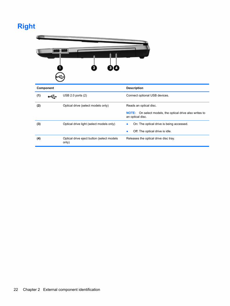
Right
Component Description
(1) USB 2.0 ports (2) Connect optional USB devices.
(2) Optical drive (select models only) Reads an optical disc.
NOTE: On select models, the optical drive also writes toan optical disc.
(3) Optical drive light (select models only) ● On: The optical drive is being accessed.
● Off: The optical drive is idle.
(4) Optical drive eject button (select modelsonly)
Releases the optical drive disc tray.
22 Chapter 2 External component identification
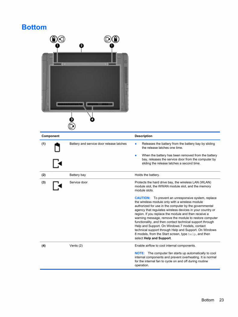
Bottom
Component Description
(1) Battery and service door release latches ● Releases the battery from the battery bay by slidingthe release latches one time.
● When the battery has been removed from the batterybay, releases the service door from the computer bysliding the release latches a second time.
(2) Battery bay Holds the battery.
(3) Service door Protects the hard drive bay, the wireless LAN (WLAN)module slot, the WWAN module slot, and the memorymodule slots.
CAUTION: To prevent an unresponsive system, replacethe wireless module only with a wireless moduleauthorized for use in the computer by the governmentalagency that regulates wireless devices in your country orregion. If you replace the module and then receive awarning message, remove the module to restore computerfunctionality, and then contact technical support throughHelp and Support. On Windows 7 models, contacttechnical support through Help and Support. On Windows8 models, from the Start screen, type help, and thenselect Help and Support.
(4) Vents (2) Enable airflow to cool internal components.
NOTE: The computer fan starts up automatically to coolinternal components and prevent overheating. It is normalfor the internal fan to cycle on and off during routineoperation.
Bottom 23

3 Illustrated parts catalog
Service tag and PCID label
Service tag
When ordering parts or requesting information, provide the computer serial number and modeldescription provided on the service tag.
● Product name (1). This is the product name affixed to the front of the computer.
● Serial number (s/n) (2). This is an alphanumeric identifier that is unique to each product.
● Part number/Product number (p/n) (3). This number provides specific information about theproduct's hardware components. The part number helps a service technician to determine whatcomponents and parts are needed.
● Warranty period (4). This number describes the duration (in years) of the warranty period for thecomputer.
● Model description (select models only) (5). This is the alphanumeric identifier used to locatedocuments, drivers, and support for the computer.
24 Chapter 3 Illustrated parts catalog
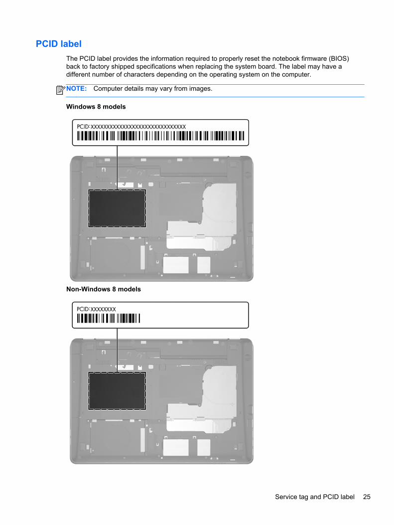
PCID label
The PCID label provides the information required to properly reset the notebook firmware (BIOS)back to factory shipped specifications when replacing the system board. The label may have adifferent number of characters depending on the operating system on the computer.
NOTE: Computer details may vary from images.
Windows 8 models
Non-Windows 8 models
Service tag and PCID label 25
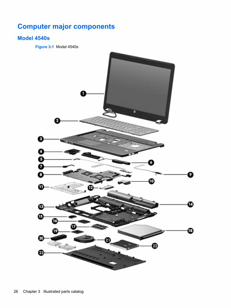
Computer major components
Model 4540s
Figure 3-1 Model 4540s
26 Chapter 3 Illustrated parts catalog
Item Description Spare part number
(1) Display panel
39.6-cm (15.6-inch) HD, anti-glare, without webcam 683481-001
39.6-cm (15.6-inch) HD, anti-glare, with webcam 683482-001
39.6-cm (15.6-inch) HD, anti-glare, with webcam and WWAN 683483-001
(2) Keyboard (includes cable)
NOTE: For a detailed list of available keyboards, see Sequential part number listingon page 39.
For use in models without Windows 8 683491-xxx
For use in models with Windows 8 702237-xxx
(3) Top cover (includes touchpad assembly and cable)
With a fingerprint reader 683506-001
Without a fingerprint reader 683507-001
(4) Audio board 683475-001
(5) Function board/Power button board assembly (includes cable) 683486-001
(6) Speaker assembly 683505-001
(7) RTC battery 683502-001
(8) System board (includes replacement thermal material)
For use in models without Windows 8:
● UMA graphics with WWAN 683496-001
● UMA graphics without WWAN 683495-001
● 1-GB discrete graphics memory 683493-001
● 2-GB discrete graphics memory 683494-001
For use in models with Windows 8:
● Windows 8 Standard and UMA graphics with WWAN 683496-501
● Windows 8 Professional and UMA graphics with WWAN 683496-601
● Windows 8 Standard and UMA graphics without WWAN 683495-501
● Windows 8 Professional and UMA graphics without WWAN 683495-601
● Windows 8 Standard and 1-GB discrete graphics memory 683493-501
● Windows 8 Professional and 1-GB discrete graphics memory 683493-601
● Windows 8 Standard and 2-GB discrete graphics memory 683494-501
● Windows 8 Professional and 2-GB discrete graphics memory 683494-601
(9) Fingerprint reader assembly (includes cable, bracket, and screws) 683485-001
(10) Optical drive extension board 683498-001
(11) Heat shield 687696-001
Computer major components 27

Item Description Spare part number
(12) Hard drive extension board 683487-001
(13) Base enclosure 683476-001
(14) Battery, Li-ion
9-cell (93 WHr, 2.8 Ah) 633809-001
6-cell (47 WHr, 2.2 Ah) 633805-001
(15) WLAN module
Atheros 9485GN 802.11b/g/n 1x1 WiFi and 3012 Bluetooth 4.0 Combo Adapter 655795-001
Broadcom 4313GN 802.11b/g/n 1x1 WiFi and 20702 Bluetooth 4.0 Combo Adapter 657325-001
Intel Centrino Wireless-N 2230 670290-001
Intel Centrino Advanced-N 6235 670292-001
Ralink WLAN Ralink Ripple3 RT5390F_802.11 b/g/n 1x1 PCIe HMC 670691-001
Atheros AR9485 802.11b/g/n 1x1 WiFi Adapter 675794-001
Atheros AR9565 802.11bgn 1x1 WiFi + BT4.0 combo Adapter 690019-001
Ralink RT3290LE 802.11bgn 1x1 Wi-Fi and Bluetooth 4.0 Combo Adapter 690020-001
Ralink RT5390R 802.11bgn 1x1 Wi-Fi Adapter 691415-001
(16) WWAN modules
Ericsson F5321 HSPA+ with GPS 668969-001
Sierra MC8355 HSPA/CDMA with GPS 634400-001
(17) Memory modules (PC3-12800, 1600-MHz, DDR3)
4-GB 641369-001
2-GB 652972-001
(18) Optical drive (includes bracket, bezel, and screws)
DVD±RW Double-Layer Drive 683500-001
Blu-ray ROM DVD±RW SuperMulti DL Drive 683499-001
(19) Processor (includes thermal material)
Intel Core i7 processor, Quad Core
3632QM, 2.2-GHz processor with 6-MB L3 cache 701658-001
3612QM, 2.1-GHz processor with 6-MB L3 cache 680647-001
Intel Core i5 processors, Dual Core
3360M, 2.8-GHz processor with 3-MB L3 cache (includes thermal grease) 681953-001
3320M, 2.6-GHz processor with 3-MB L3 cache (includes thermal grease) 681952-001
2450M, 2.5-GHz processor with 3-MB L3 cache (includes thermal grease) 676359-001
Intel Core i3 processors, Dual Core
3120M, 2.5-GHz processor with 3-MB L3 cache (includes thermal grease) 700627-001
28 Chapter 3 Illustrated parts catalog
Item Description Spare part number
3110M, 2.3-GHz processor with 3-MB L3 cache (includes thermal grease) 682417-001
2370M, 2.4-GHz processor with 3-MB L3 cache (includes thermal grease) 677152-001
2350M, 2.3-GHz processor with 3-MB L3 cache (includes thermal grease) 653340-001
Intel Pentium processor, Dual Core
2020M, 2.4-GHz, with 2-MB L3 cache 700628-001
B980, 2.4-GHz, with 2-MB L3 cache 692428-001
B970, 2.3-GHz, with 2-MB L3 cache 676785-001
Intel Celeron processor
B840, 1.9-GHz, with 2-MB L3 cache 664663-001
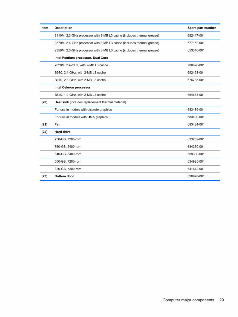
(20) Heat sink (includes replacement thermal material)
For use in models with discrete graphics 683489-001
For use in models with UMA graphics 683490-001
(21) Fan 683484-001
(22) Hard drive
750-GB, 7200-rpm 633252-001
750-GB, 5400-rpm 634250-001
640-GB, 5400-rpm 669300-001
500-GB, 7200-rpm 634925-001
320-GB, 7200-rpm 641672-001
(23) Bottom door 690978-001
Computer major components 29
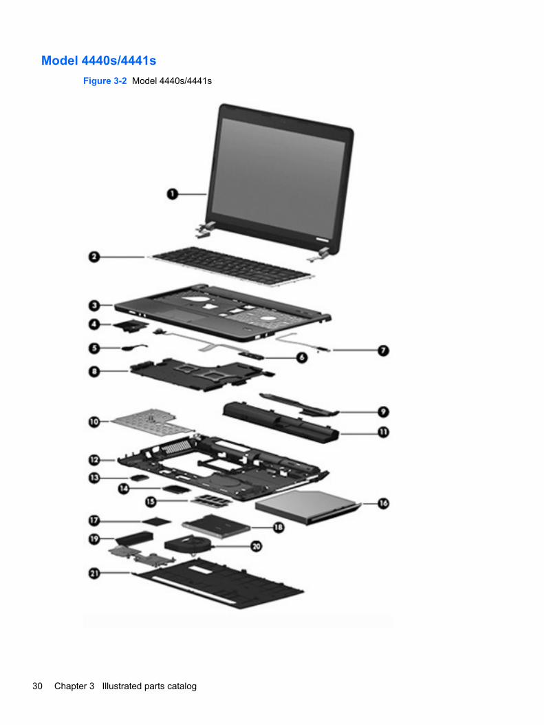
Model 4440s/4441s
Figure 3-2 Model 4440s/4441s
30 Chapter 3 Illustrated parts catalog
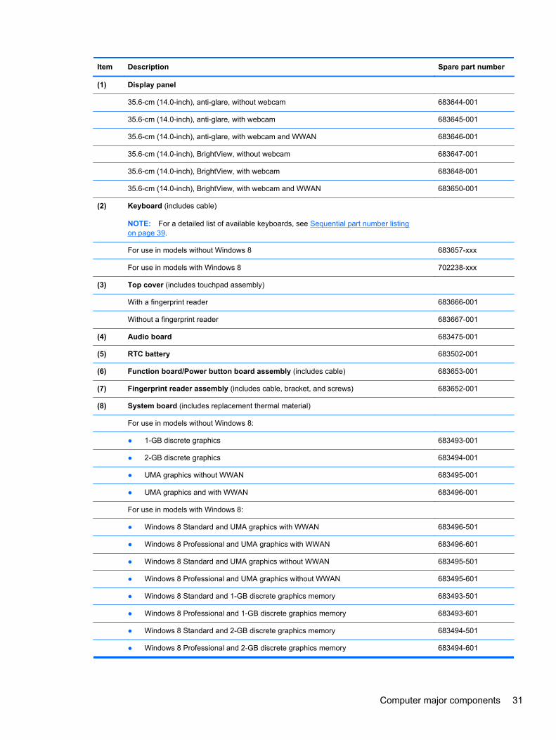
Item Description Spare part number
(1) Display panel
35.6-cm (14.0-inch), anti-glare, without webcam 683644-001
35.6-cm (14.0-inch), anti-glare, with webcam 683645-001
35.6-cm (14.0-inch), anti-glare, with webcam and WWAN 683646-001
35.6-cm (14.0-inch), BrightView, without webcam 683647-001
35.6-cm (14.0-inch), BrightView, with webcam 683648-001
35.6-cm (14.0-inch), BrightView, with webcam and WWAN 683650-001
(2) Keyboard (includes cable)
NOTE: For a detailed list of available keyboards, see Sequential part number listingon page 39.
For use in models without Windows 8 683657-xxx
For use in models with Windows 8 702238-xxx
(3) Top cover (includes touchpad assembly)
With a fingerprint reader 683666-001
Without a fingerprint reader 683667-001
(4) Audio board 683475-001
(5) RTC battery 683502-001
(6) Function board/Power button board assembly (includes cable) 683653-001
(7) Fingerprint reader assembly (includes cable, bracket, and screws) 683652-001
(8) System board (includes replacement thermal material)
For use in models without Windows 8:
● 1-GB discrete graphics 683493-001
● 2-GB discrete graphics 683494-001
● UMA graphics without WWAN 683495-001
● UMA graphics and with WWAN 683496-001
For use in models with Windows 8:
● Windows 8 Standard and UMA graphics with WWAN 683496-501
● Windows 8 Professional and UMA graphics with WWAN 683496-601
● Windows 8 Standard and UMA graphics without WWAN 683495-501
● Windows 8 Professional and UMA graphics without WWAN 683495-601
● Windows 8 Standard and 1-GB discrete graphics memory 683493-501
● Windows 8 Professional and 1-GB discrete graphics memory 683493-601
● Windows 8 Standard and 2-GB discrete graphics memory 683494-501
● Windows 8 Professional and 2-GB discrete graphics memory 683494-601
Computer major components 31

Item Description Spare part number
(9) Speaker assembly 683665-001
(10) Heat shield 683497-001
(11) Battery, Li-ion
9-cell (93 WHr, 2.8 Ah) 633809-001
6-cell (47 WHr, 2.2 Ah) 633805-001
(12) Base enclosure 683639-001
(13) WLAN module
Atheros 9485GN 802.11b/g/n 1x1 WiFi and 3012 Bluetooth 4.0 Combo Adapter 655795-001
Broadcom 4313GN 802.11b/g/n 1x1 WiFi and 20702 Bluetooth 4.0 Combo Adapter 657325-001
Intel Centrino Wireless-N 2230 670290-001
Intel Centrino Advanced-N 6235 670292-001
Ralink WLAN Ralink Ripple3 RT5390F_802.11 b/g/n 1x1 PCIe HMC 670691-001
Atheros AR9485 802.11b/g/n 1x1 WiFi Adapter 675794-001
Atheros AR9565 802.11bgn 1x1 WiFi + BT4.0 combo Adapter 690019-001
Ralink RT3290LE 802.11bgn 1x1 Wi-Fi and Bluetooth 4.0 Combo Adapter 690020-001
Ralink RT5390R 802.11bgn 1x1 Wi-Fi Adapter 691415-001
(14) WWAN modules
Ericsson F5321 HSPA+ with GPS 668969-001
Sierra MC8355 HSPA/CDMA with GPS 634400-001
(15) Memory modules (PC3-12800, 1600-MHz, DDR3)
4-GB 641369-001
2-GB 652972-001
(16) Optical drive (includes bracket, bezel, and screws)
DVD±RW and CD-RW Super Multi Double-Layer Combo Drive 691110-001
Blu-ray ROM DVD±RW SuperMulti DL Drive 691111-001
(17) Processor (includes thermal material)
Intel Core i7 processor, Quad Core
3632QM, 2.2-GHz processor with 6-MB L3 cache 701658-001
3612QM, 2.1-GHz processor with 6-MB L3 cache 680647-001
Intel Core i5 processors, Dual Core
3360M, 2.8-GHz processor with 3-MB L3 cache (includes thermal grease) 681953-001
3320M, 2.6-GHz processor with 3-MB L3 cache (includes thermal grease) 681952-001
2450M, 2.5-GHz processor with 3-MB L3 cache (includes thermal grease) 676359-001
Intel Core i3 processors, Dual Core
32 Chapter 3 Illustrated parts catalog
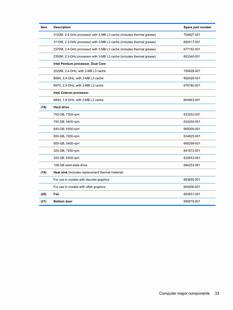
Item Description Spare part number
3120M, 2.5-GHz processor with 3-MB L3 cache (includes thermal grease) 700627-001
3110M, 2.3-GHz processor with 3-MB L3 cache (includes thermal grease) 682417-001
2370M, 2.4-GHz processor with 3-MB L3 cache (includes thermal grease) 677152-001
2350M, 2.3-GHz processor with 3-MB L3 cache (includes thermal grease) 653340-001
Intel Pentium processor, Dual Core
2020M, 2.4-GHz, with 2-MB L3 cache 700628-001
B980, 2.4-GHz, with 2-MB L3 cache 692428-001
B970, 2.3-GHz, with 2-MB L3 cache 676785-001
Intel Celeron processor
B840, 1.9-GHz, with 2-MB L3 cache 664663-001
(18) Hard drive
750-GB, 7200-rpm 633252-001
750-GB, 5400-rpm 634250-001
640-GB, 5400-rpm 669300-001
500-GB, 7200-rpm 634925-001
500-GB, 5400-rpm 669299-001
320-GB, 7200-rpm 641672-001
320-GB, 5400-rpm 622643-001
128-GB solid-state drive 684253-001
(19) Heat sink (includes replacement thermal material)
For use in models with discrete graphics 683655-001
For use in models with UMA graphics 683656-001
(20) Fan 683651-001
(21) Bottom door 690979-001
Computer major components 33
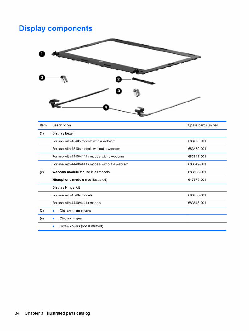
Display components
Item Description Spare part number
(1) Display bezel
For use with 4540s models with a webcam 683478-001
For use with 4540s models without a webcam 683479-001
For use with 4440/4441s models with a webcam 683641-001
For use with 4440/4441s models without a webcam 683642-001
(2) Webcam module for use in all models 683508-001
Microphone module (not illustrated) 647675-001
Display Hinge Kit
For use with 4540s models 683480-001
For use with 4440/4441s models 683643-001
(3) ● Display hinge covers
(4) ● Display hinges
● Screw covers (not illustrated)
34 Chapter 3 Illustrated parts catalog
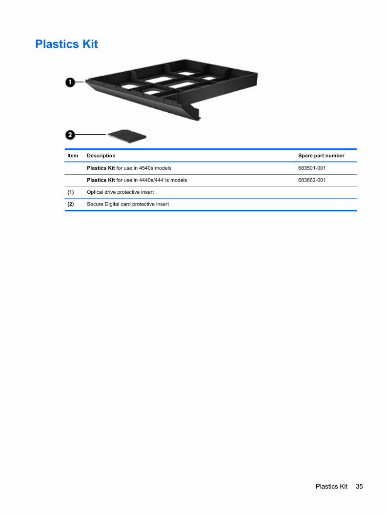
Plastics Kit
Item Description Spare part number
Plastics Kit for use in 4540s models 683501-001
Plastics Kit for use in 4440s/4441s models 683662-001
(1) Optical drive protective insert
(2) Secure Digital card protective insert
Plastics Kit 35
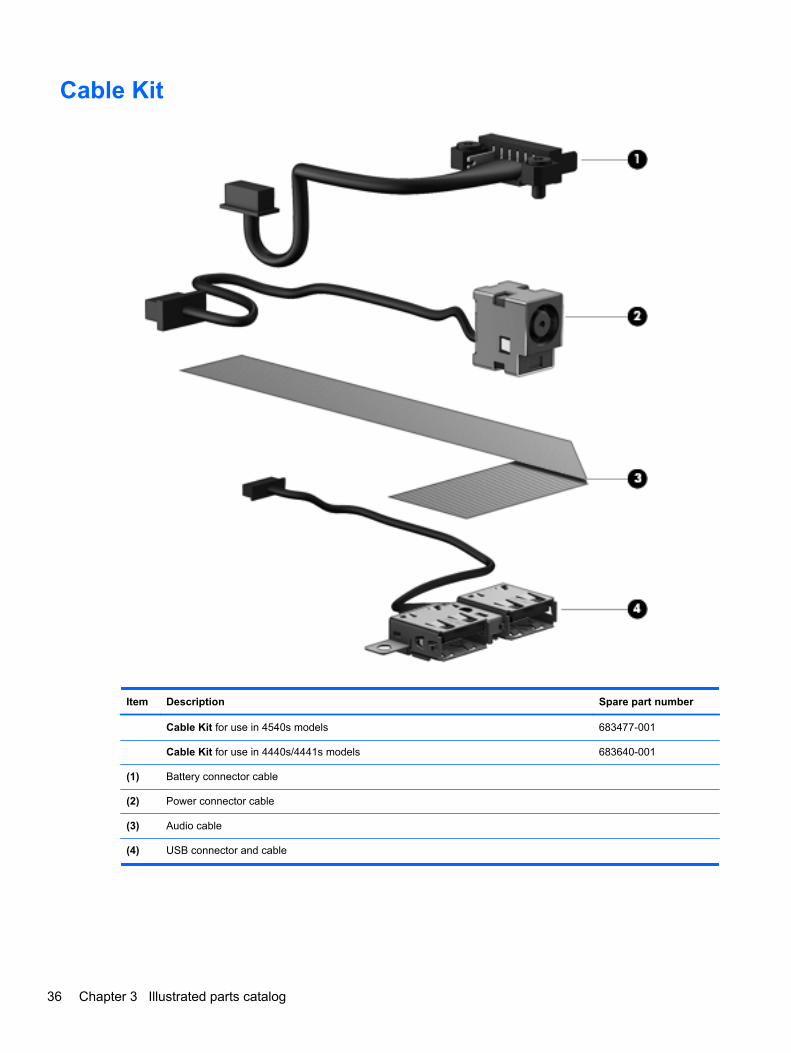
Cable Kit
Item Description Spare part number
Cable Kit for use in 4540s models 683477-001
Cable Kit for use in 4440s/4441s models 683640-001
(1) Battery connector cable
(2) Power connector cable
(3) Audio cable
(4) USB connector and cable
36 Chapter 3 Illustrated parts catalog
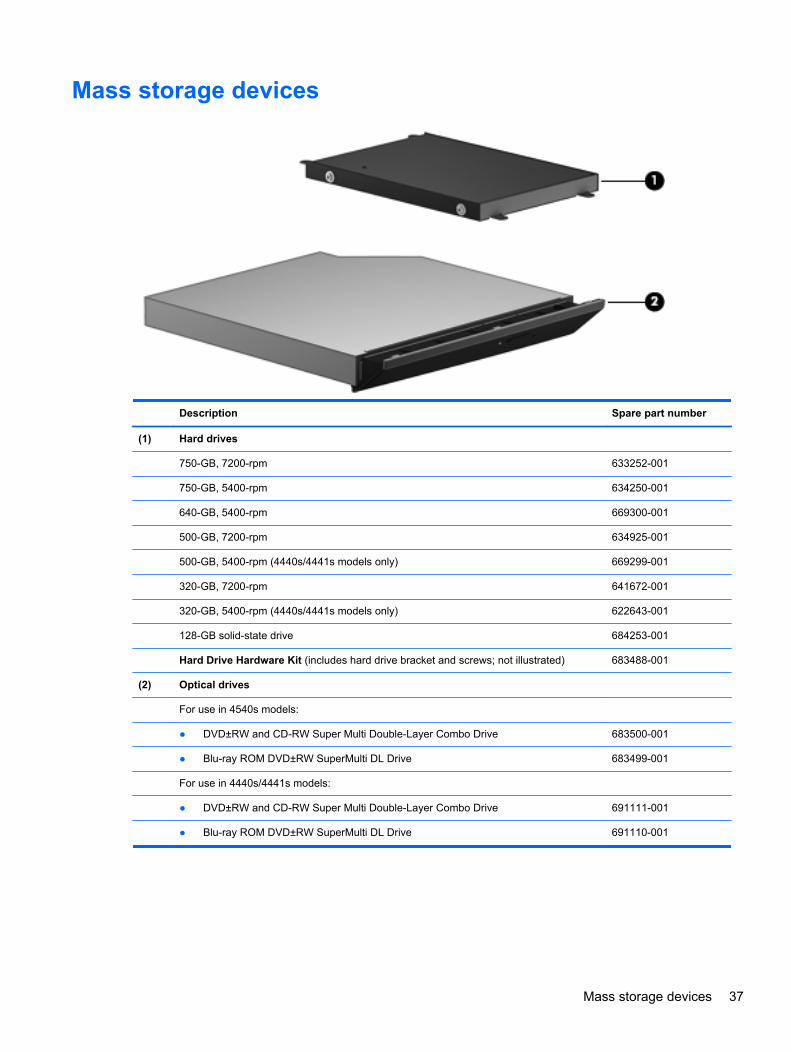
Mass storage devices
Description Spare part number
(1) Hard drives
750-GB, 7200-rpm 633252-001
750-GB, 5400-rpm 634250-001
640-GB, 5400-rpm 669300-001
500-GB, 7200-rpm 634925-001
500-GB, 5400-rpm (4440s/4441s models only) 669299-001
320-GB, 7200-rpm 641672-001
320-GB, 5400-rpm (4440s/4441s models only) 622643-001
128-GB solid-state drive 684253-001
Hard Drive Hardware Kit (includes hard drive bracket and screws; not illustrated) 683488-001
(2) Optical drives
For use in 4540s models:
● DVD±RW and CD-RW Super Multi Double-Layer Combo Drive 683500-001
● Blu-ray ROM DVD±RW SuperMulti DL Drive 683499-001
For use in 4440s/4441s models:
● DVD±RW and CD-RW Super Multi Double-Layer Combo Drive 691111-001
● Blu-ray ROM DVD±RW SuperMulti DL Drive 691110-001
Mass storage devices 37
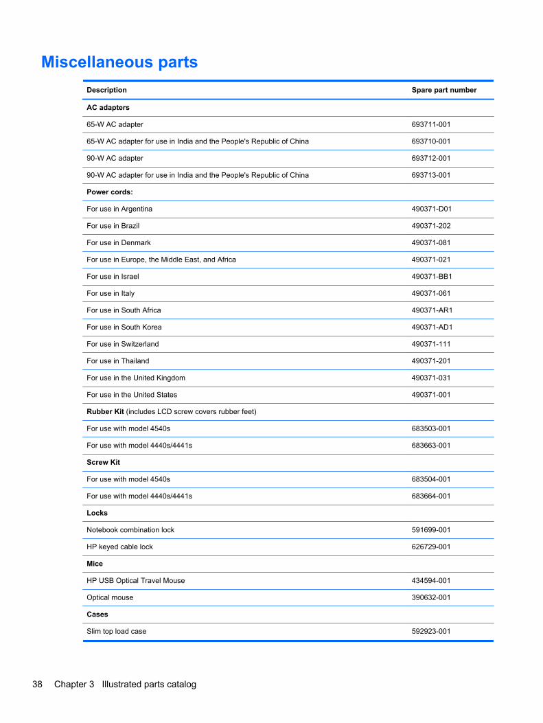
Miscellaneous parts
Description Spare part number
AC adapters
65-W AC adapter 693711-001
65-W AC adapter for use in India and the People's Republic of China 693710-001
90-W AC adapter 693712-001
90-W AC adapter for use in India and the People's Republic of China 693713-001
Power cords:
For use in Argentina 490371-D01
For use in Brazil 490371-202
For use in Denmark 490371-081
For use in Europe, the Middle East, and Africa 490371-021
For use in Israel 490371-BB1
For use in Italy 490371-061
For use in South Africa 490371-AR1
For use in South Korea 490371-AD1
For use in Switzerland 490371-111
For use in Thailand 490371-201
For use in the United Kingdom 490371-031
For use in the United States 490371-001
Rubber Kit (includes LCD screw covers rubber feet)
For use with model 4540s 683503-001
For use with model 4440s/4441s 683663-001
Screw Kit
For use with model 4540s 683504-001
For use with model 4440s/4441s 683664-001
Locks
Notebook combination lock 591699-001
HP keyed cable lock 626729-001
Mice
HP USB Optical Travel Mouse 434594-001
Optical mouse 390632-001
Cases
Slim top load case 592923-001
38 Chapter 3 Illustrated parts catalog
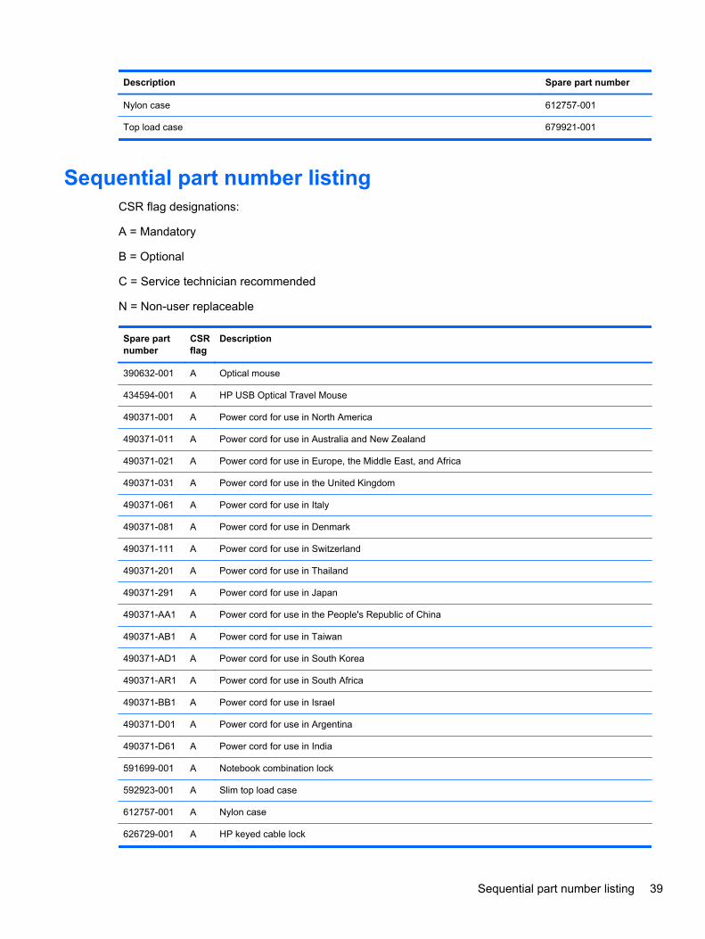
Description Spare part number
Nylon case 612757-001
Top load case 679921-001
Sequential part number listingCSR flag designations:
A = Mandatory
B = Optional
C = Service technician recommended
N = Non-user replaceable
Spare partnumber
CSRflag
Description
390632-001 A Optical mouse
434594-001 A HP USB Optical Travel Mouse
490371-001 A Power cord for use in North America
490371-011 A Power cord for use in Australia and New Zealand
490371-021 A Power cord for use in Europe, the Middle East, and Africa
490371-031 A Power cord for use in the United Kingdom
490371-061 A Power cord for use in Italy
490371-081 A Power cord for use in Denmark
490371-111 A Power cord for use in Switzerland
490371-201 A Power cord for use in Thailand
490371-291 A Power cord for use in Japan
490371-AA1 A Power cord for use in the People's Republic of China
490371-AB1 A Power cord for use in Taiwan
490371-AD1 A Power cord for use in South Korea
490371-AR1 A Power cord for use in South Africa
490371-BB1 A Power cord for use in Israel
490371-D01 A Power cord for use in Argentina
490371-D61 A Power cord for use in India
591699-001 A Notebook combination lock
592923-001 A Slim top load case
612757-001 A Nylon case
626729-001 A HP keyed cable lock
Sequential part number listing 39
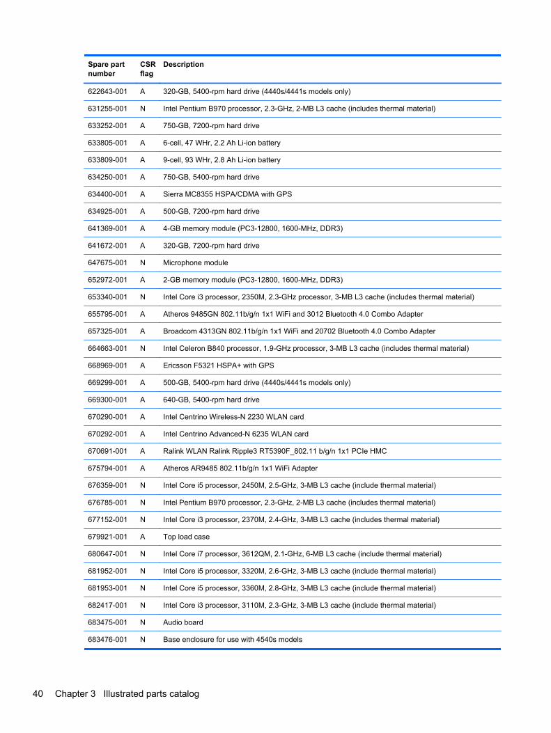
Spare partnumber
CSRflag
Description
622643-001 A 320-GB, 5400-rpm hard drive (4440s/4441s models only)
631255-001 N Intel Pentium B970 processor, 2.3-GHz, 2-MB L3 cache (includes thermal material)
633252-001 A 750-GB, 7200-rpm hard drive
633805-001 A 6-cell, 47 WHr, 2.2 Ah Li-ion battery
633809-001 A 9-cell, 93 WHr, 2.8 Ah Li-ion battery
634250-001 A 750-GB, 5400-rpm hard drive
634400-001 A Sierra MC8355 HSPA/CDMA with GPS
634925-001 A 500-GB, 7200-rpm hard drive
641369-001 A 4-GB memory module (PC3-12800, 1600-MHz, DDR3)
641672-001 A 320-GB, 7200-rpm hard drive
647675-001 N Microphone module
652972-001 A 2-GB memory module (PC3-12800, 1600-MHz, DDR3)
653340-001 N Intel Core i3 processor, 2350M, 2.3-GHz processor, 3-MB L3 cache (includes thermal material)
655795-001 A Atheros 9485GN 802.11b/g/n 1x1 WiFi and 3012 Bluetooth 4.0 Combo Adapter
657325-001 A Broadcom 4313GN 802.11b/g/n 1x1 WiFi and 20702 Bluetooth 4.0 Combo Adapter
664663-001 N Intel Celeron B840 processor, 1.9-GHz processor, 3-MB L3 cache (includes thermal material)
668969-001 A Ericsson F5321 HSPA+ with GPS
669299-001 A 500-GB, 5400-rpm hard drive (4440s/4441s models only)
669300-001 A 640-GB, 5400-rpm hard drive
670290-001 A Intel Centrino Wireless-N 2230 WLAN card
670292-001 A Intel Centrino Advanced-N 6235 WLAN card
670691-001 A Ralink WLAN Ralink Ripple3 RT5390F_802.11 b/g/n 1x1 PCIe HMC
675794-001 A Atheros AR9485 802.11b/g/n 1x1 WiFi Adapter
676359-001 N Intel Core i5 processor, 2450M, 2.5-GHz, 3-MB L3 cache (include thermal material)
676785-001 N Intel Pentium B970 processor, 2.3-GHz, 2-MB L3 cache (includes thermal material)
677152-001 N Intel Core i3 processor, 2370M, 2.4-GHz, 3-MB L3 cache (includes thermal material)
679921-001 A Top load case
680647-001 N Intel Core i7 processor, 3612QM, 2.1-GHz, 6-MB L3 cache (include thermal material)
681952-001 N Intel Core i5 processor, 3320M, 2.6-GHz, 3-MB L3 cache (include thermal material)
681953-001 N Intel Core i5 processor, 3360M, 2.8-GHz, 3-MB L3 cache (include thermal material)
682417-001 N Intel Core i3 processor, 3110M, 2.3-GHz, 3-MB L3 cache (include thermal material)
683475-001 N Audio board
683476-001 N Base enclosure for use with 4540s models
40 Chapter 3 Illustrated parts catalog
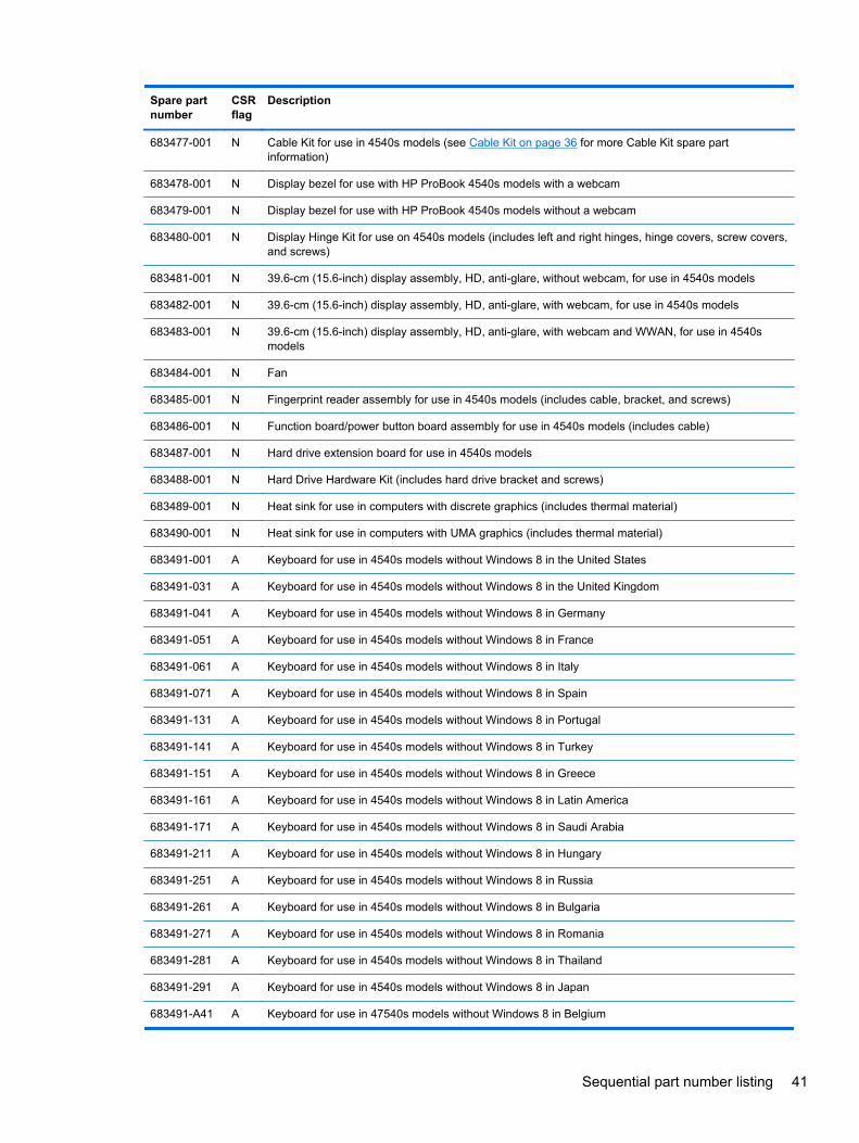
Spare partnumber
CSRflag
Description
683477-001 N Cable Kit for use in 4540s models (see Cable Kit on page 36 for more Cable Kit spare partinformation)
683478-001 N Display bezel for use with HP ProBook 4540s models with a webcam
683479-001 N Display bezel for use with HP ProBook 4540s models without a webcam
683480-001 N Display Hinge Kit for use on 4540s models (includes left and right hinges, hinge covers, screw covers,and screws)
683481-001 N 39.6-cm (15.6-inch) display assembly, HD, anti-glare, without webcam, for use in 4540s models
683482-001 N 39.6-cm (15.6-inch) display assembly, HD, anti-glare, with webcam, for use in 4540s models
683483-001 N 39.6-cm (15.6-inch) display assembly, HD, anti-glare, with webcam and WWAN, for use in 4540smodels
683484-001 N Fan
683485-001 N Fingerprint reader assembly for use in 4540s models (includes cable, bracket, and screws)
683486-001 N Function board/power button board assembly for use in 4540s models (includes cable)
683487-001 N Hard drive extension board for use in 4540s models
683488-001 N Hard Drive Hardware Kit (includes hard drive bracket and screws)
683489-001 N Heat sink for use in computers with discrete graphics (includes thermal material)
683490-001 N Heat sink for use in computers with UMA graphics (includes thermal material)
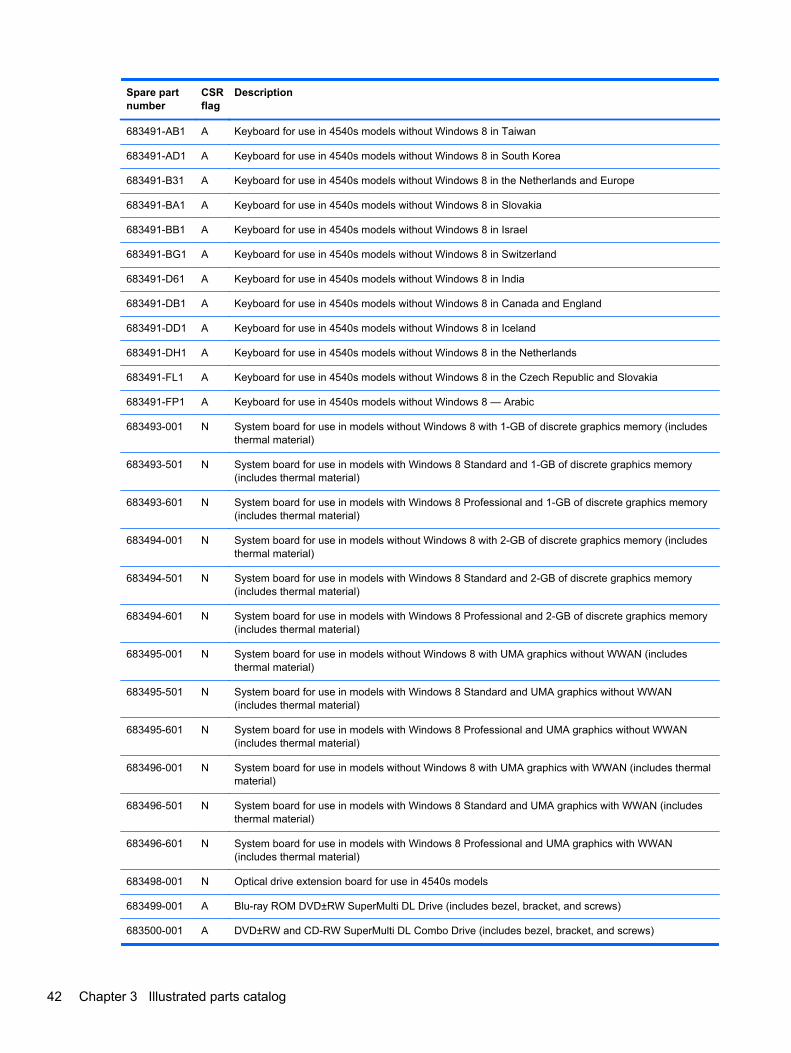
683491-001 A Keyboard for use in 4540s models without Windows 8 in the United States
683491-031 A Keyboard for use in 4540s models without Windows 8 in the United Kingdom
683491-041 A Keyboard for use in 4540s models without Windows 8 in Germany
683491-051 A Keyboard for use in 4540s models without Windows 8 in France
683491-061 A Keyboard for use in 4540s models without Windows 8 in Italy
683491-071 A Keyboard for use in 4540s models without Windows 8 in Spain
683491-131 A Keyboard for use in 4540s models without Windows 8 in Portugal
683491-141 A Keyboard for use in 4540s models without Windows 8 in Turkey
683491-151 A Keyboard for use in 4540s models without Windows 8 in Greece
683491-161 A Keyboard for use in 4540s models without Windows 8 in Latin America
683491-171 A Keyboard for use in 4540s models without Windows 8 in Saudi Arabia
683491-211 A Keyboard for use in 4540s models without Windows 8 in Hungary
683491-251 A Keyboard for use in 4540s models without Windows 8 in Russia
683491-261 A Keyboard for use in 4540s models without Windows 8 in Bulgaria
683491-271 A Keyboard for use in 4540s models without Windows 8 in Romania
683491-281 A Keyboard for use in 4540s models without Windows 8 in Thailand
683491-291 A Keyboard for use in 4540s models without Windows 8 in Japan
683491-A41 A Keyboard for use in 47540s models without Windows 8 in Belgium
Sequential part number listing 41
Spare partnumber
CSRflag
Description
683491-AB1 A Keyboard for use in 4540s models without Windows 8 in Taiwan
683491-AD1 A Keyboard for use in 4540s models without Windows 8 in South Korea
683491-B31 A Keyboard for use in 4540s models without Windows 8 in the Netherlands and Europe
683491-BA1 A Keyboard for use in 4540s models without Windows 8 in Slovakia
683491-BB1 A Keyboard for use in 4540s models without Windows 8 in Israel
683491-BG1 A Keyboard for use in 4540s models without Windows 8 in Switzerland
683491-D61 A Keyboard for use in 4540s models without Windows 8 in India
683491-DB1 A Keyboard for use in 4540s models without Windows 8 in Canada and England
683491-DD1 A Keyboard for use in 4540s models without Windows 8 in Iceland
683491-DH1 A Keyboard for use in 4540s models without Windows 8 in the Netherlands
683491-FL1 A Keyboard for use in 4540s models without Windows 8 in the Czech Republic and Slovakia
683491-FP1 A Keyboard for use in 4540s models without Windows 8 — Arabic
683493-001 N System board for use in models without Windows 8 with 1-GB of discrete graphics memory (includesthermal material)
683493-501 N System board for use in models with Windows 8 Standard and 1-GB of discrete graphics memory(includes thermal material)
683493-601 N System board for use in models with Windows 8 Professional and 1-GB of discrete graphics memory(includes thermal material)
683494-001 N System board for use in models without Windows 8 with 2-GB of discrete graphics memory (includesthermal material)
683494-501 N System board for use in models with Windows 8 Standard and 2-GB of discrete graphics memory(includes thermal material)
683494-601 N System board for use in models with Windows 8 Professional and 2-GB of discrete graphics memory(includes thermal material)
683495-001 N System board for use in models without Windows 8 with UMA graphics without WWAN (includesthermal material)
683495-501 N System board for use in models with Windows 8 Standard and UMA graphics without WWAN(includes thermal material)
683495-601 N System board for use in models with Windows 8 Professional and UMA graphics without WWAN(includes thermal material)
683496-001 N System board for use in models without Windows 8 with UMA graphics with WWAN (includes thermalmaterial)
683496-501 N System board for use in models with Windows 8 Standard and UMA graphics with WWAN (includesthermal material)
683496-601 N System board for use in models with Windows 8 Professional and UMA graphics with WWAN(includes thermal material)
683498-001 N Optical drive extension board for use in 4540s models
683499-001 A Blu-ray ROM DVD±RW SuperMulti DL Drive (includes bezel, bracket, and screws)
683500-001 A DVD±RW and CD-RW SuperMulti DL Combo Drive (includes bezel, bracket, and screws)
42 Chapter 3 Illustrated parts catalog
Spare partnumber
CSRflag
Description
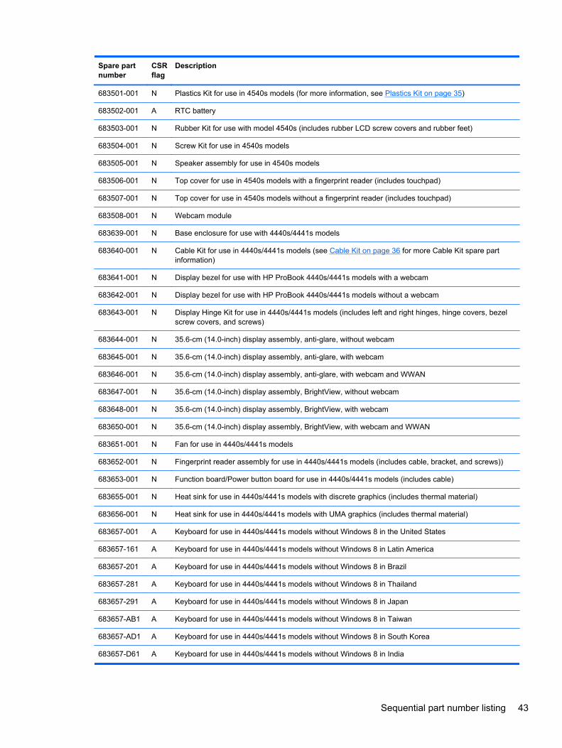
683501-001 N Plastics Kit for use in 4540s models (for more information, see Plastics Kit on page 35)
683502-001 A RTC battery
683503-001 N Rubber Kit for use with model 4540s (includes rubber LCD screw covers and rubber feet)
683504-001 N Screw Kit for use in 4540s models
683505-001 N Speaker assembly for use in 4540s models
683506-001 N Top cover for use in 4540s models with a fingerprint reader (includes touchpad)
683507-001 N Top cover for use in 4540s models without a fingerprint reader (includes touchpad)
683508-001 N Webcam module
683639-001 N Base enclosure for use with 4440s/4441s models
683640-001 N Cable Kit for use in 4440s/4441s models (see Cable Kit on page 36 for more Cable Kit spare partinformation)
683641-001 N Display bezel for use with HP ProBook 4440s/4441s models with a webcam
683642-001 N Display bezel for use with HP ProBook 4440s/4441s models without a webcam
683643-001 N Display Hinge Kit for use in 4440s/4441s models (includes left and right hinges, hinge covers, bezelscrew covers, and screws)
683644-001 N 35.6-cm (14.0-inch) display assembly, anti-glare, without webcam
683645-001 N 35.6-cm (14.0-inch) display assembly, anti-glare, with webcam
683646-001 N 35.6-cm (14.0-inch) display assembly, anti-glare, with webcam and WWAN
683647-001 N 35.6-cm (14.0-inch) display assembly, BrightView, without webcam
683648-001 N 35.6-cm (14.0-inch) display assembly, BrightView, with webcam
683650-001 N 35.6-cm (14.0-inch) display assembly, BrightView, with webcam and WWAN
683651-001 N Fan for use in 4440s/4441s models
683652-001 N Fingerprint reader assembly for use in 4440s/4441s models (includes cable, bracket, and screws))
683653-001 N Function board/Power button board for use in 4440s/4441s models (includes cable)
683655-001 N Heat sink for use in 4440s/4441s models with discrete graphics (includes thermal material)
683656-001 N Heat sink for use in 4440s/4441s models with UMA graphics (includes thermal material)
683657-001 A Keyboard for use in 4440s/4441s models without Windows 8 in the United States
683657-161 A Keyboard for use in 4440s/4441s models without Windows 8 in Latin America
683657-201 A Keyboard for use in 4440s/4441s models without Windows 8 in Brazil
683657-281 A Keyboard for use in 4440s/4441s models without Windows 8 in Thailand
683657-291 A Keyboard for use in 4440s/4441s models without Windows 8 in Japan
683657-AB1 A Keyboard for use in 4440s/4441s models without Windows 8 in Taiwan
683657-AD1 A Keyboard for use in 4440s/4441s models without Windows 8 in South Korea
683657-D61 A Keyboard for use in 4440s/4441s models without Windows 8 in India
Sequential part number listing 43
Spare partnumber
CSRflag
Description
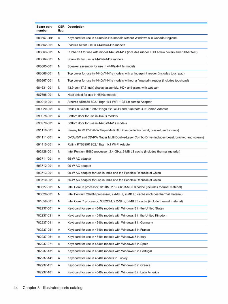
683657-DB1 A Keyboard for use in 4440s/4441s models without Windows 8 in Canada/England
683662-001 N Plastics Kit for use in 4440s/4441s models
683663-001 N Rubber Kit for use with model 4440s/4441s (includes rubber LCD screw covers and rubber feet)
683664-001 N Screw Kit for use in 4440s/4441s models
683665-001 N Speaker assembly for use in 4440s/4441s models
683666-001 N Top cover for use in 4440s/4441s models with a fingerprint reader (includes touchpad)
683667-001 N Top cover for use in 4440s/4441s models without a fingerprint reader (includes touchpad)
684631-001 N 43.9-cm (17.3-inch) display assembly, HD+ anti-glare, with webcam
687696-001 N Heat shield for use in 4540s models
690019-001 A Atheros AR9565 802.11bgn 1x1 WiFi + BT4.0 combo Adapter
690020-001 A Ralink RT3290LE 802.11bgn 1x1 Wi-Fi and Bluetooth 4.0 Combo Adapter
690978-001 A Bottom door for use in 4540s models
690979-001 A Bottom door for use in 4440s/4441s models
691110-001 A Blu-ray ROM DVD±RW SuperMulti DL Drive (includes bezel, bracket, and screws)
691111-001 A DVD±RW and CD-RW Super Multi Double-Layer Combo Drive (includes bezel, bracket, and screws)
691415-001 A Ralink RT5390R 802.11bgn 1x1 Wi-Fi Adapter
692428-001 N Intel Pentium B980 processor, 2.4-GHz, 2-MB L3 cache (includes thermal material)
693711-001 A 65-W AC adapter
693712-001 A 90-W AC adapter
693713-001 A 90-W AC adapter for use in India and the People's Republic of China
693710-001 A 65-W AC adapter for use in India and the People's Republic of China
700627-001 N Intel Core i3 processor, 3120M, 2.5-GHz, 3-MB L3 cache (includes thermal material)
700628-001 N Intel Pentium 2020M processor, 2.4-GHz, 2-MB L3 cache (includes thermal material)
701658-001 N Intel Core i7 processor, 3632QM, 2.2-GHz, 6-MB L3 cache (include thermal material)
702237-001 A Keyboard for use in 4540s models with Windows 8 in the United States
702237-031 A Keyboard for use in 4540s models with Windows 8 in the United Kingdom
702237-041 A Keyboard for use in 4540s models with Windows 8 in Germany
702237-051 A Keyboard for use in 4540s models with Windows 8 in France
702237-061 A Keyboard for use in 4540s models with Windows 8 in Italy
702237-071 A Keyboard for use in 4540s models with Windows 8 in Spain
702237-131 A Keyboard for use in 4540s models with Windows 8 in Portugal
702237-141 A Keyboard for use in 4540s models in Turkey
702237-151 A Keyboard for use in 4540s models with Windows 8 in Greece
702237-161 A Keyboard for use in 4540s models with Windows 8 in Latin America
44 Chapter 3 Illustrated parts catalog
Spare partnumber
CSRflag
Description
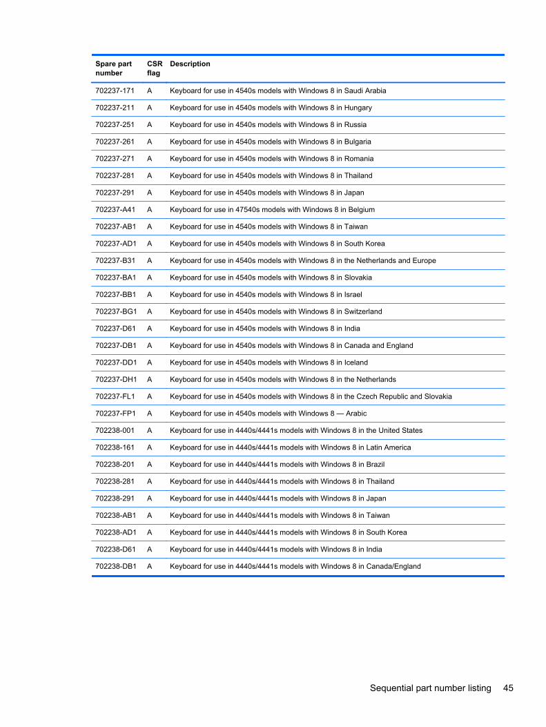
702237-171 A Keyboard for use in 4540s models with Windows 8 in Saudi Arabia
702237-211 A Keyboard for use in 4540s models with Windows 8 in Hungary
702237-251 A Keyboard for use in 4540s models with Windows 8 in Russia
702237-261 A Keyboard for use in 4540s models with Windows 8 in Bulgaria
702237-271 A Keyboard for use in 4540s models with Windows 8 in Romania
702237-281 A Keyboard for use in 4540s models with Windows 8 in Thailand
702237-291 A Keyboard for use in 4540s models with Windows 8 in Japan
702237-A41 A Keyboard for use in 47540s models with Windows 8 in Belgium
702237-AB1 A Keyboard for use in 4540s models with Windows 8 in Taiwan
702237-AD1 A Keyboard for use in 4540s models with Windows 8 in South Korea
702237-B31 A Keyboard for use in 4540s models with Windows 8 in the Netherlands and Europe
702237-BA1 A Keyboard for use in 4540s models with Windows 8 in Slovakia
702237-BB1 A Keyboard for use in 4540s models with Windows 8 in Israel
702237-BG1 A Keyboard for use in 4540s models with Windows 8 in Switzerland
702237-D61 A Keyboard for use in 4540s models with Windows 8 in India
702237-DB1 A Keyboard for use in 4540s models with Windows 8 in Canada and England
702237-DD1 A Keyboard for use in 4540s models with Windows 8 in Iceland
702237-DH1 A Keyboard for use in 4540s models with Windows 8 in the Netherlands
702237-FL1 A Keyboard for use in 4540s models with Windows 8 in the Czech Republic and Slovakia
702237-FP1 A Keyboard for use in 4540s models with Windows 8 — Arabic
702238-001 A Keyboard for use in 4440s/4441s models with Windows 8 in the United States
702238-161 A Keyboard for use in 4440s/4441s models with Windows 8 in Latin America
702238-201 A Keyboard for use in 4440s/4441s models with Windows 8 in Brazil
702238-281 A Keyboard for use in 4440s/4441s models with Windows 8 in Thailand
702238-291 A Keyboard for use in 4440s/4441s models with Windows 8 in Japan
702238-AB1 A Keyboard for use in 4440s/4441s models with Windows 8 in Taiwan
702238-AD1 A Keyboard for use in 4440s/4441s models with Windows 8 in South Korea
702238-D61 A Keyboard for use in 4440s/4441s models with Windows 8 in India
702238-DB1 A Keyboard for use in 4440s/4441s models with Windows 8 in Canada/England
Sequential part number listing 45
4 Removal and replacement procedures
Preliminary replacement requirements
Tools required
You will need the following tools to complete the removal and replacement procedures:
● Flat-bladed screwdriver
● Phillips P0 and P1 screwdrivers
● Torx T8 screwdriver
Service considerations
The following sections include some of the considerations that you must keep in mind duringdisassembly and assembly procedures.
NOTE: As you remove each subassembly from the computer, place the subassembly (and allaccompanying screws) away from the work area to prevent damage.
Plastic parts
CAUTION: Using excessive force during disassembly and reassembly can damage plastic parts.Use care when handling the plastic parts. Apply pressure only at the points designated in themaintenance instructions.
46 Chapter 4 Removal and replacement procedures
Cables and connectors
CAUTION: When servicing the computer, be sure that cables are placed in their proper locationsduring the reassembly process. Improper cable placement can damage the computer.
Cables must be handled with extreme care to avoid damage. Apply only the tension required tounseat or seat the cables during removal and insertion. Handle cables by the connector wheneverpossible. In all cases, avoid bending, twisting, or tearing cables. Be sure that cables are routed insuch a way that they cannot be caught or snagged by parts being removed or replaced. Handle flexcables with extreme care; these cables tear easily.
Drive handling
CAUTION: Drives are fragile components that must be handled with care. To prevent damage tothe computer, damage to a drive, or loss of information, observe these precautions:
Before removing or inserting a hard drive, shut down the computer. If you are unsure whether thecomputer is off or in Hibernation, turn the computer on, and then shut it down through the operatingsystem.
Before handling a drive, be sure that you are discharged of static electricity. While handling a drive,avoid touching the connector.
Before removing a diskette drive or optical drive, be sure that a diskette or disc is not in the drive andbe sure that the optical drive tray is closed.
Handle drives on surfaces covered with at least one inch of shock-proof foam.
Avoid dropping drives from any height onto any surface.
After removing a hard drive, an optical drive, or a diskette drive, place it in a static-proof bag.
Avoid exposing a hard drive to products that have magnetic fields, such as monitors or speakers.
Avoid exposing a drive to temperature extremes or liquids.
If a drive must be mailed, place the drive in a bubble pack mailer or other suitable form of protectivepackaging and label the package “FRAGILE.”
Preliminary replacement requirements 47
Grounding guidelines
Electrostatic discharge damage
Electronic components are sensitive to electrostatic discharge (ESD). Circuitry design and structuredetermine the degree of sensitivity. Networks built into many integrated circuits provide someprotection, but in many cases, ESD contains enough power to alter device parameters or meltsilicon junctions.
A discharge of static electricity from a finger or other conductor can destroy static-sensitive devices ormicrocircuitry. Even if the spark is neither felt nor heard, damage may have occurred.
An electronic device exposed to ESD may not be affected at all and can work perfectly throughout anormal cycle. Or the device may function normally for a while, and then degrade in the internal layers,reducing its life expectancy.
CAUTION: To prevent damage to the computer when you are removing or installing internalcomponents, observe these precautions:
Keep components in their electrostatic-safe containers until you are ready to install them.
Use nonmagnetic tools.
Before touching an electronic component, discharge static electricity by using the guidelinesdescribed in this section.
Avoid touching pins, leads, and circuitry. Handle electronic components as little as possible.
If you remove a component, place it in an electrostatic-safe container.
The following table shows how humidity affects the electrostatic voltage levels generated by differentactivities.
CAUTION: A product can be degraded by as little as 700 V.
Typical electrostatic voltage levels
Relative humidity
Event 10% 40% 55%
Walking across carpet 35,000 V 15,000 V 7,500 V
Walking across vinyl floor 12,000 V 5,000 V 3,000 V
Motions of bench worker 6,000 V 800 V 400 V
Removing DIPS from plastic tube 2,000 V 700 V 400 V
Removing DIPS from vinyl tray 11,500 V 4,000 V 2,000 V
Removing DIPS from Styrofoam 14,500 V 5,000 V 3,500 V
Removing bubble pack from PCB 26,500 V 20,000 V 7,000 V
Packing PCBs in foam-lined box 21,000 V 11,000 V 5,000 V
48 Chapter 4 Removal and replacement procedures

Packaging and transporting guidelines
Follow these grounding guidelines when packaging and transporting equipment:
● To avoid hand contact, transport products in static-safe tubes, bags, or boxes.
● Protect ESD-sensitive parts and assemblies with conductive or approved containers orpackaging.
● Keep ESD-sensitive parts in their containers until the parts arrive at static-free workstations.
● Place items on a grounded surface before removing items from their containers.
● Always be properly grounded when touching a component or assembly.
● Store reusable ESD-sensitive parts from assemblies in protective packaging or nonconductivefoam.
● Use transporters and conveyors made of antistatic belts and roller bushings. Be sure thatmechanized equipment used for moving materials is wired to ground and that proper materialsare selected to avoid static charging. When grounding is not possible, use an ionizer to dissipateelectric charges.
Workstation guidelines
Follow these grounding workstation guidelines:
● Cover the workstation with approved static-shielding material.
● Use a wrist strap connected to a properly grounded work surface and use properly groundedtools and equipment.
● Use conductive field service tools, such as cutters, screwdrivers, and vacuums.
● When fixtures must directly contact dissipative surfaces, use fixtures made only of static-safematerials.
● Keep the work area free of nonconductive materials, such as ordinary plastic assembly aids andStyrofoam.
● Handle ESD-sensitive components, parts, and assemblies by the case or PCM laminate. Handlethese items only at static-free workstations.
● Avoid contact with pins, leads, or circuitry.
● Turn off power and input signals before inserting or removing connectors or test equipment.
Preliminary replacement requirements 49
Equipment guidelines
Grounding equipment must include either a wrist strap or a foot strap at a grounded workstation.
● When seated, wear a wrist strap connected to a grounded system. Wrist straps are flexiblestraps with a minimum of one megohm ±10% resistance in the ground cords. To provide properground, wear a strap snugly against the skin at all times. On grounded mats with banana-plugconnectors, use alligator clips to connect a wrist strap.
● When standing, use foot straps and a grounded floor mat. Foot straps (heel, toe, or boot straps)can be used at standing workstations and are compatible with most types of shoes or boots. Onconductive floors or dissipative floor mats, use foot straps on both feet with a minimum of onemegohm resistance between the operator and ground. To be effective, the conductive stripsmust be worn in contact with the skin.
The following grounding equipment is recommended to prevent electrostatic damage:
● Antistatic tapes
● Antistatic smocks, aprons, and sleeve protectors
● Conductive bins and other assembly or soldering aids
● Nonconductive foam
● Conductive tabletop workstations with ground cords of one megohm resistance
● Static-dissipative tables or floor mats with hard ties to the ground
● Field service kits
● Static awareness labels
● Material-handling packages
● Nonconductive plastic bags, tubes, or boxes
● Metal tote boxes
● Electrostatic voltage levels and protective materials
The following table lists the shielding protection provided by antistatic bags and floor mats.
Material Use Voltage protection level
Antistatic plastic Bags 1,500 V
Carbon-loaded plastic Floor mats 7,500 V
Metallized laminate Floor mats 5,000 V
50 Chapter 4 Removal and replacement procedures

Component replacement proceduresThis chapter provides removal and replacement procedures.
There are as many as 95 screws and screw locks, in 15 different sizes, that must be removed,replaced, or loosened when servicing the computer. Make special note of each screw and screw locksize and location during removal and replacement.
Component replacement procedures 51
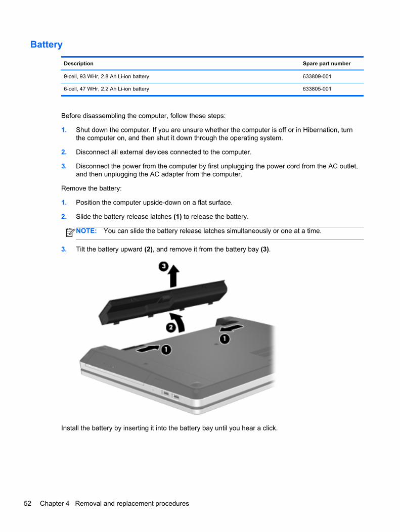
Battery
Description Spare part number
9-cell, 93 WHr, 2.8 Ah Li-ion battery 633809-001
6-cell, 47 WHr, 2.2 Ah Li-ion battery 633805-001
Before disassembling the computer, follow these steps:
1. Shut down the computer. If you are unsure whether the computer is off or in Hibernation, turnthe computer on, and then shut it down through the operating system.
2. Disconnect all external devices connected to the computer.
3. Disconnect the power from the computer by first unplugging the power cord from the AC outlet,and then unplugging the AC adapter from the computer.
Remove the battery:
1. Position the computer upside-down on a flat surface.
2. Slide the battery release latches (1) to release the battery.
NOTE: You can slide the battery release latches simultaneously or one at a time.
3. Tilt the battery upward (2), and remove it from the battery bay (3).
Install the battery by inserting it into the battery bay until you hear a click.
52 Chapter 4 Removal and replacement procedures
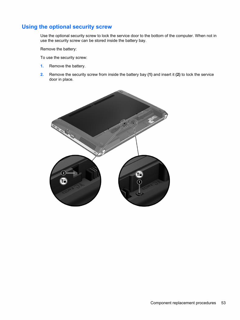
Using the optional security screw
Use the optional security screw to lock the service door to the bottom of the computer. When not inuse the security screw can be stored inside the battery bay.
Remove the battery:
To use the security screw:
1. Remove the battery.
2. Remove the security screw from inside the battery bay (1) and insert it (2) to lock the servicedoor in place.
Component replacement procedures 53
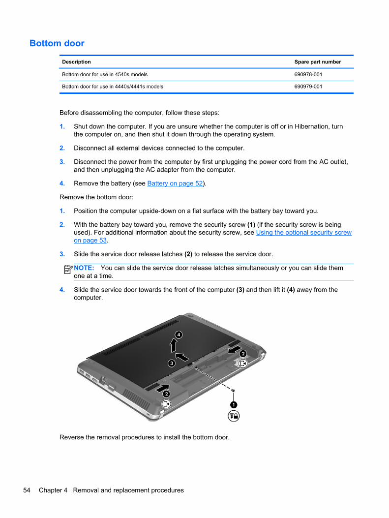
Bottom door
Description Spare part number
Bottom door for use in 4540s models 690978-001
Bottom door for use in 4440s/4441s models 690979-001
Before disassembling the computer, follow these steps:
1. Shut down the computer. If you are unsure whether the computer is off or in Hibernation, turnthe computer on, and then shut it down through the operating system.
2. Disconnect all external devices connected to the computer.
3. Disconnect the power from the computer by first unplugging the power cord from the AC outlet,and then unplugging the AC adapter from the computer.
4. Remove the battery (see Battery on page 52).
Remove the bottom door:
1. Position the computer upside-down on a flat surface with the battery bay toward you.
2. With the battery bay toward you, remove the security screw (1) (if the security screw is beingused). For additional information about the security screw, see Using the optional security screwon page 53.
3. Slide the service door release latches (2) to release the service door.
NOTE: You can slide the service door release latches simultaneously or you can slide themone at a time.
4. Slide the service door towards the front of the computer (3) and then lift it (4) away from thecomputer.
Reverse the removal procedures to install the bottom door.
54 Chapter 4 Removal and replacement procedures
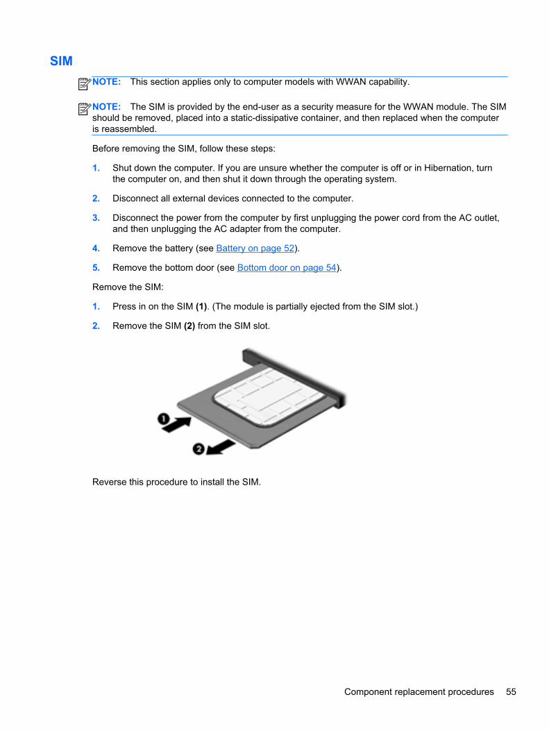
SIM
NOTE: This section applies only to computer models with WWAN capability.
NOTE: The SIM is provided by the end-user as a security measure for the WWAN module. The SIMshould be removed, placed into a static-dissipative container, and then replaced when the computeris reassembled.
Before removing the SIM, follow these steps:
1. Shut down the computer. If you are unsure whether the computer is off or in Hibernation, turnthe computer on, and then shut it down through the operating system.
2. Disconnect all external devices connected to the computer.
3. Disconnect the power from the computer by first unplugging the power cord from the AC outlet,and then unplugging the AC adapter from the computer.
4. Remove the battery (see Battery on page 52).
5. Remove the bottom door (see Bottom door on page 54).
Remove the SIM:
1. Press in on the SIM (1). (The module is partially ejected from the SIM slot.)
2. Remove the SIM (2) from the SIM slot.
Reverse this procedure to install the SIM.
Component replacement procedures 55
Optical drive
NOTE: All optical drive spare part kits include an optical drive bezel, bracket, and screws.
Description Spare part number
For use in 4540s models
DVD±RW and CD-RW Super Multi Double-Layer Combo Drive 683500-001
Blu-ray ROM DVD±RW SuperMulti DL Drive 683499-001
For use in 4440s/4441s models
DVD±RW and CD-RW Super Multi Double-Layer Combo Drive 691111-001
Blu-ray ROM DVD±RW SuperMulti DL Drive 691110-001
Before removing the optical drive, follow these steps:
1. Shut down the computer. If you are unsure whether the computer is off or in Hibernation, turnthe computer on, and then shut it down through the operating system.
2. Disconnect all external devices connected to the computer.
3. Disconnect the power from the computer by first unplugging the power cord from the AC outlet,and then unplugging the AC adapter from the computer.
4. Remove the battery (see Battery on page 52).
5. Remove the bottom door (see Bottom door on page 54).
Remove the optical drive:
1. Position the computer upside-down.
2. Remove the Phillips PM2.5×6.0 screw (1) that secures the optical drive to the computer.
3. Push the optical drive tab (2) to release the optical drive from the computer.
56 Chapter 4 Removal and replacement procedures
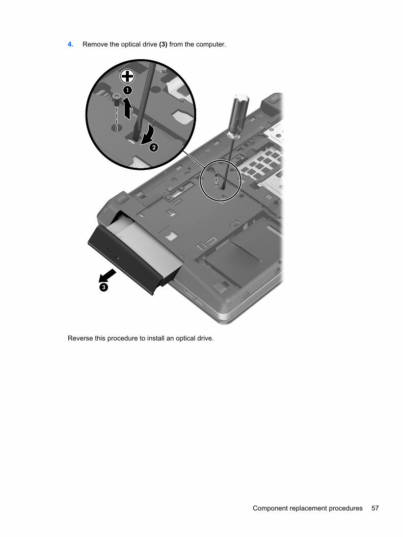
4. Remove the optical drive (3) from the computer.
Reverse this procedure to install an optical drive.
Component replacement procedures 57
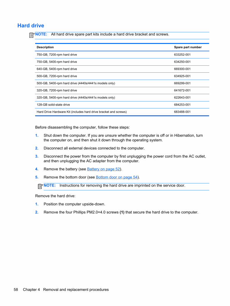
Hard drive
NOTE: All hard drive spare part kits include a hard drive bracket and screws.
Description Spare part number
750-GB, 7200-rpm hard drive 633252-001
750-GB, 5400-rpm hard drive 634250-001
640-GB, 5400-rpm hard drive 669300-001
500-GB, 7200-rpm hard drive 634925-001
500-GB, 5400-rpm hard drive (4440s/4441s models only) 669299-001
320-GB, 7200-rpm hard drive 641672-001
320-GB, 5400-rpm hard drive (4440s/4441s models only) 622643-001
128-GB solid-state drive 684253-001
Hard Drive Hardware Kit (includes hard drive bracket and screws) 683488-001
Before disassembling the computer, follow these steps:
1. Shut down the computer. If you are unsure whether the computer is off or in Hibernation, turnthe computer on, and then shut it down through the operating system.
2. Disconnect all external devices connected to the computer.
3. Disconnect the power from the computer by first unplugging the power cord from the AC outlet,and then unplugging the AC adapter from the computer.
4. Remove the battery (see Battery on page 52).
5. Remove the bottom door (see Bottom door on page 54).
NOTE: Instructions for removing the hard drive are imprinted on the service door.
Remove the hard drive:
1. Position the computer upside-down.
2. Remove the four Phillips PM2.0×4.0 screws (1) that secure the hard drive to the computer.
58 Chapter 4 Removal and replacement procedures
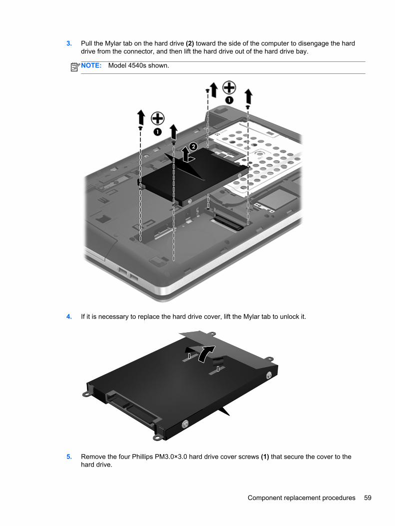
3. Pull the Mylar tab on the hard drive (2) toward the side of the computer to disengage the harddrive from the connector, and then lift the hard drive out of the hard drive bay.
NOTE: Model 4540s shown.
4. If it is necessary to replace the hard drive cover, lift the Mylar tab to unlock it.
5. Remove the four Phillips PM3.0×3.0 hard drive cover screws (1) that secure the cover to thehard drive.
Component replacement procedures 59
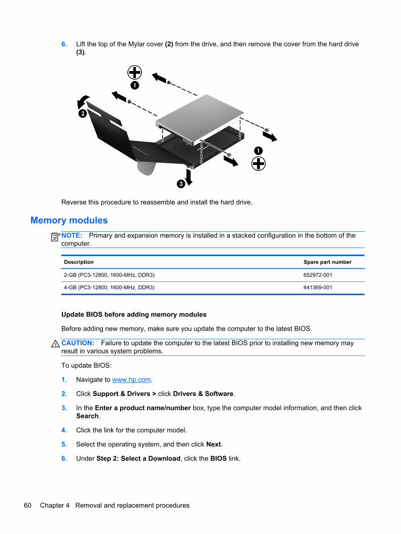
6. Lift the top of the Mylar cover (2) from the drive, and then remove the cover from the hard drive(3).
Reverse this procedure to reassemble and install the hard drive.
Memory modules
NOTE: Primary and expansion memory is installed in a stacked configuration in the bottom of thecomputer.
Description Spare part number
2-GB (PC3-12800, 1600-MHz, DDR3) 652972-001
4-GB (PC3-12800, 1600-MHz, DDR3) 641369-001
Update BIOS before adding memory modules
Before adding new memory, make sure you update the computer to the latest BIOS.
CAUTION: Failure to update the computer to the latest BIOS prior to installing new memory mayresult in various system problems.
To update BIOS:
1. Navigate to www.hp.com.
2. Click Support & Drivers > click Drivers & Software.
3. In the Enter a product name/number box, type the computer model information, and then clickSearch.
4. Click the link for the computer model.
5. Select the operating system, and then click Next.
6. Under Step 2: Select a Download, click the BIOS link.
60 Chapter 4 Removal and replacement procedures
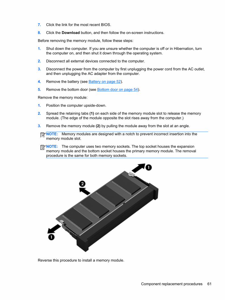
7. Click the link for the most recent BIOS.
8. Click the Download button, and then follow the on-screen instructions.
Before removing the memory module, follow these steps:
1. Shut down the computer. If you are unsure whether the computer is off or in Hibernation, turnthe computer on, and then shut it down through the operating system.
2. Disconnect all external devices connected to the computer.
3. Disconnect the power from the computer by first unplugging the power cord from the AC outlet,and then unplugging the AC adapter from the computer.
4. Remove the battery (see Battery on page 52).
5. Remove the bottom door (see Bottom door on page 54).
Remove the memory module:
1. Position the computer upside-down.
2. Spread the retaining tabs (1) on each side of the memory module slot to release the memorymodule. (The edge of the module opposite the slot rises away from the computer.)
3. Remove the memory module (2) by pulling the module away from the slot at an angle.
NOTE: Memory modules are designed with a notch to prevent incorrect insertion into thememory module slot.
NOTE: The computer uses two memory sockets. The top socket houses the expansionmemory module and the bottom socket houses the primary memory module. The removalprocedure is the same for both memory sockets.
Reverse this procedure to install a memory module.
Component replacement procedures 61
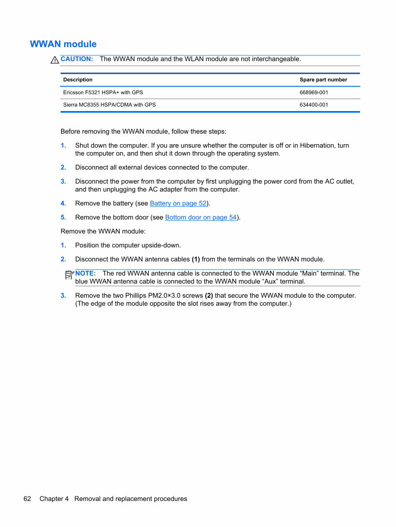
WWAN module
CAUTION: The WWAN module and the WLAN module are not interchangeable.
Description Spare part number
Ericsson F5321 HSPA+ with GPS 668969-001
Sierra MC8355 HSPA/CDMA with GPS 634400-001
Before removing the WWAN module, follow these steps:
1. Shut down the computer. If you are unsure whether the computer is off or in Hibernation, turnthe computer on, and then shut it down through the operating system.
2. Disconnect all external devices connected to the computer.
3. Disconnect the power from the computer by first unplugging the power cord from the AC outlet,and then unplugging the AC adapter from the computer.
4. Remove the battery (see Battery on page 52).
5. Remove the bottom door (see Bottom door on page 54).
Remove the WWAN module:
1. Position the computer upside-down.
2. Disconnect the WWAN antenna cables (1) from the terminals on the WWAN module.
NOTE: The red WWAN antenna cable is connected to the WWAN module “Main” terminal. Theblue WWAN antenna cable is connected to the WWAN module “Aux” terminal.
3. Remove the two Phillips PM2.0×3.0 screws (2) that secure the WWAN module to the computer.(The edge of the module opposite the slot rises away from the computer.)
62 Chapter 4 Removal and replacement procedures
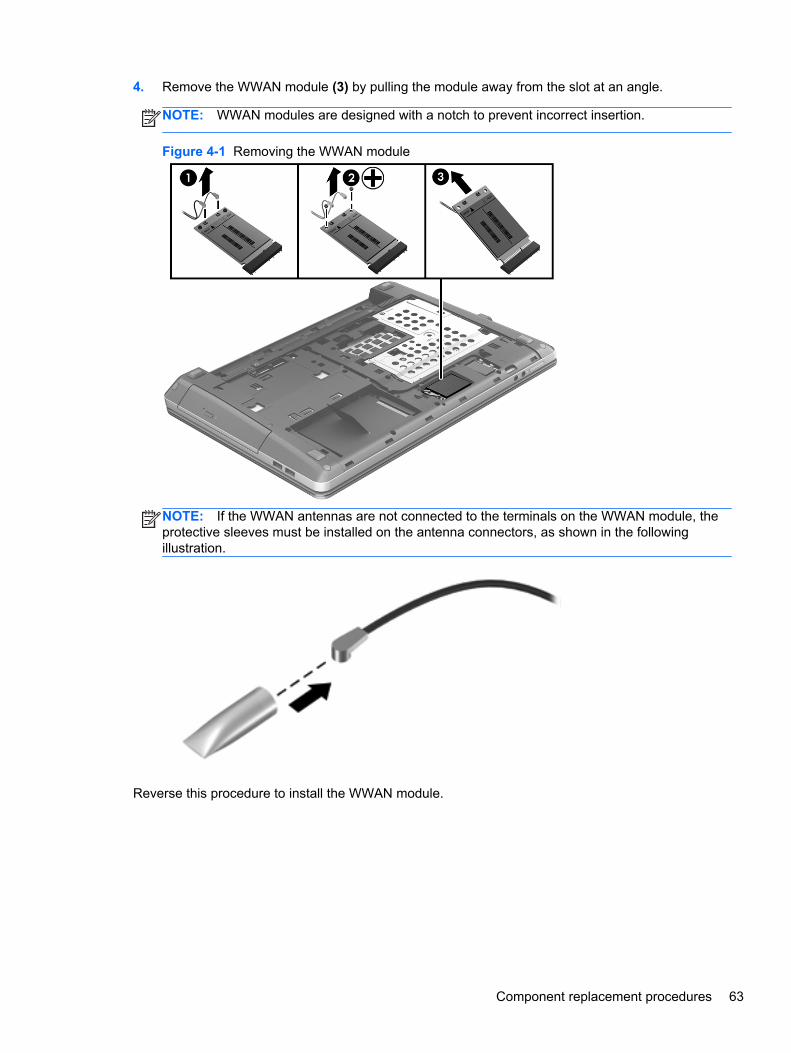
4. Remove the WWAN module (3) by pulling the module away from the slot at an angle.
NOTE: WWAN modules are designed with a notch to prevent incorrect insertion.
Figure 4-1 Removing the WWAN module
NOTE: If the WWAN antennas are not connected to the terminals on the WWAN module, theprotective sleeves must be installed on the antenna connectors, as shown in the followingillustration.
Reverse this procedure to install the WWAN module.
Component replacement procedures 63
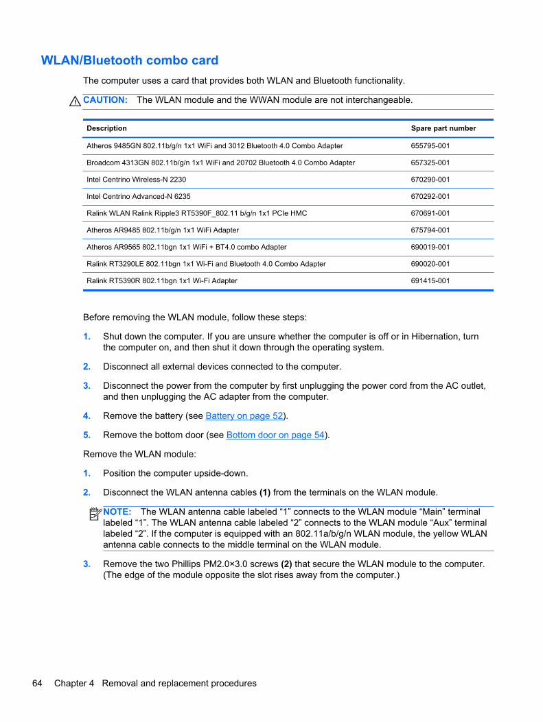
WLAN/Bluetooth combo card
The computer uses a card that provides both WLAN and Bluetooth functionality.
CAUTION: The WLAN module and the WWAN module are not interchangeable.
Description Spare part number
Atheros 9485GN 802.11b/g/n 1x1 WiFi and 3012 Bluetooth 4.0 Combo Adapter 655795-001
Broadcom 4313GN 802.11b/g/n 1x1 WiFi and 20702 Bluetooth 4.0 Combo Adapter 657325-001
Intel Centrino Wireless-N 2230 670290-001
Intel Centrino Advanced-N 6235 670292-001
Ralink WLAN Ralink Ripple3 RT5390F_802.11 b/g/n 1x1 PCIe HMC 670691-001
Atheros AR9485 802.11b/g/n 1x1 WiFi Adapter 675794-001
Atheros AR9565 802.11bgn 1x1 WiFi + BT4.0 combo Adapter 690019-001
Ralink RT3290LE 802.11bgn 1x1 Wi-Fi and Bluetooth 4.0 Combo Adapter 690020-001
Ralink RT5390R 802.11bgn 1x1 Wi-Fi Adapter 691415-001
Before removing the WLAN module, follow these steps:
1. Shut down the computer. If you are unsure whether the computer is off or in Hibernation, turnthe computer on, and then shut it down through the operating system.
2. Disconnect all external devices connected to the computer.
3. Disconnect the power from the computer by first unplugging the power cord from the AC outlet,and then unplugging the AC adapter from the computer.
4. Remove the battery (see Battery on page 52).
5. Remove the bottom door (see Bottom door on page 54).
Remove the WLAN module:
1. Position the computer upside-down.
2. Disconnect the WLAN antenna cables (1) from the terminals on the WLAN module.
NOTE: The WLAN antenna cable labeled “1” connects to the WLAN module “Main” terminallabeled “1”. The WLAN antenna cable labeled “2” connects to the WLAN module “Aux” terminallabeled “2”. If the computer is equipped with an 802.11a/b/g/n WLAN module, the yellow WLANantenna cable connects to the middle terminal on the WLAN module.
3. Remove the two Phillips PM2.0×3.0 screws (2) that secure the WLAN module to the computer.(The edge of the module opposite the slot rises away from the computer.)
64 Chapter 4 Removal and replacement procedures
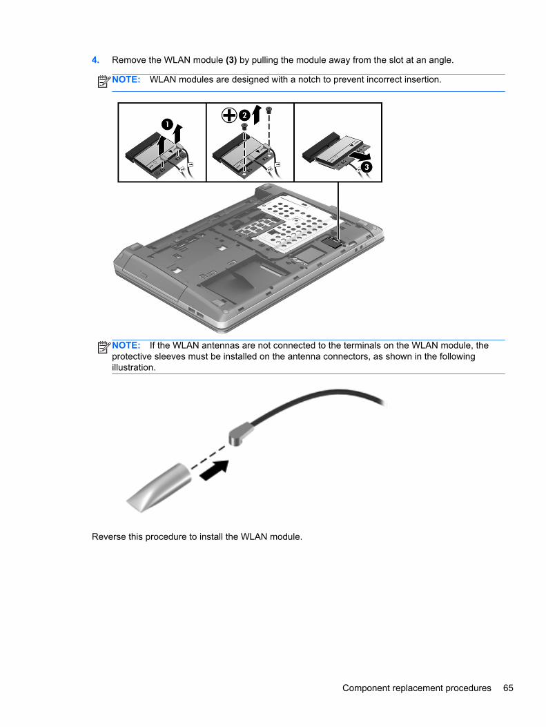
4. Remove the WLAN module (3) by pulling the module away from the slot at an angle.
NOTE: WLAN modules are designed with a notch to prevent incorrect insertion.
NOTE: If the WLAN antennas are not connected to the terminals on the WLAN module, theprotective sleeves must be installed on the antenna connectors, as shown in the followingillustration.
Reverse this procedure to install the WLAN module.
Component replacement procedures 65
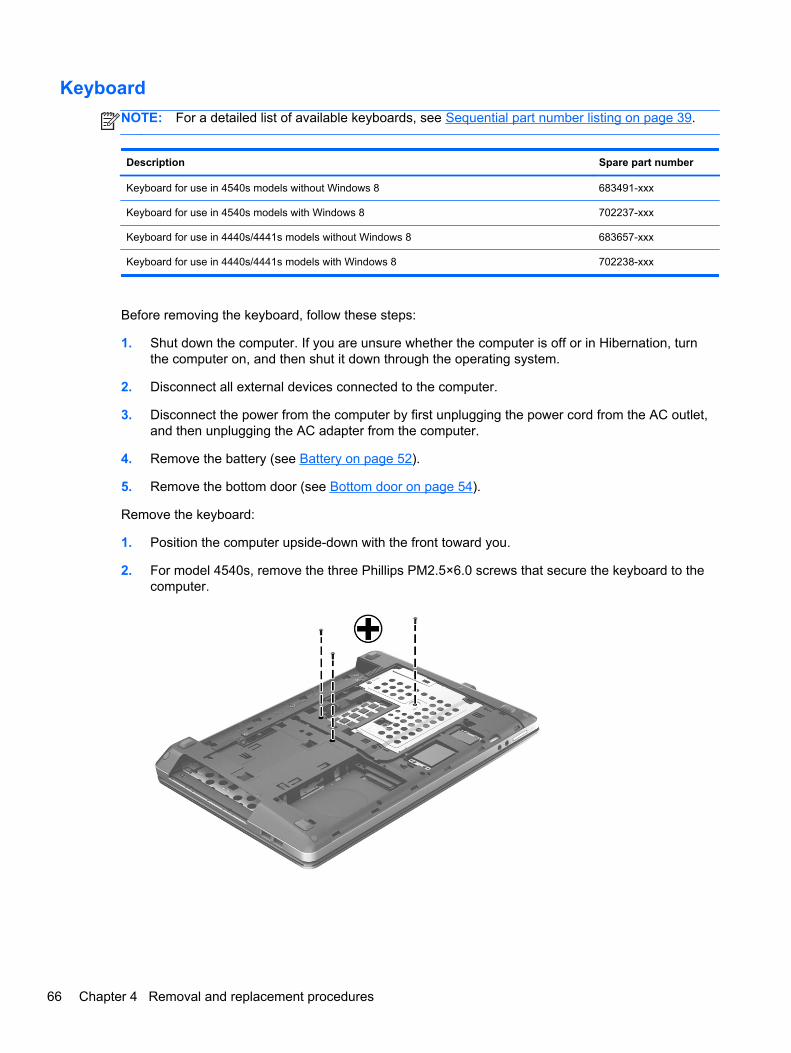
Keyboard
NOTE: For a detailed list of available keyboards, see Sequential part number listing on page 39.
Description Spare part number
Keyboard for use in 4540s models without Windows 8 683491-xxx
Keyboard for use in 4540s models with Windows 8 702237-xxx
Keyboard for use in 4440s/4441s models without Windows 8 683657-xxx
Keyboard for use in 4440s/4441s models with Windows 8 702238-xxx
Before removing the keyboard, follow these steps:
1. Shut down the computer. If you are unsure whether the computer is off or in Hibernation, turnthe computer on, and then shut it down through the operating system.
2. Disconnect all external devices connected to the computer.
3. Disconnect the power from the computer by first unplugging the power cord from the AC outlet,and then unplugging the AC adapter from the computer.
4. Remove the battery (see Battery on page 52).
5. Remove the bottom door (see Bottom door on page 54).
Remove the keyboard:
1. Position the computer upside-down with the front toward you.
2. For model 4540s, remove the three Phillips PM2.5×6.0 screws that secure the keyboard to thecomputer.
66 Chapter 4 Removal and replacement procedures

3. For model 4440s/4441s, remove the two Phillips PM2.5×6.0 screws that secure the keyboard tothe computer.
4. Position the computer right-side up with the front toward you.
5. Open the computer as far as possible.
6. Slide the keyboard downward toward the palm rest (1).
7. Lift the top of the keyboard at an angle (2), and then pull the keyboard up to remove it from thepalm rest(3).
NOTE: Only pull the keyboard up enough to release it from the computer and flip it over ontothe palm rest. Under the keyboard, the cable is connected to the system board.
Component replacement procedures 67
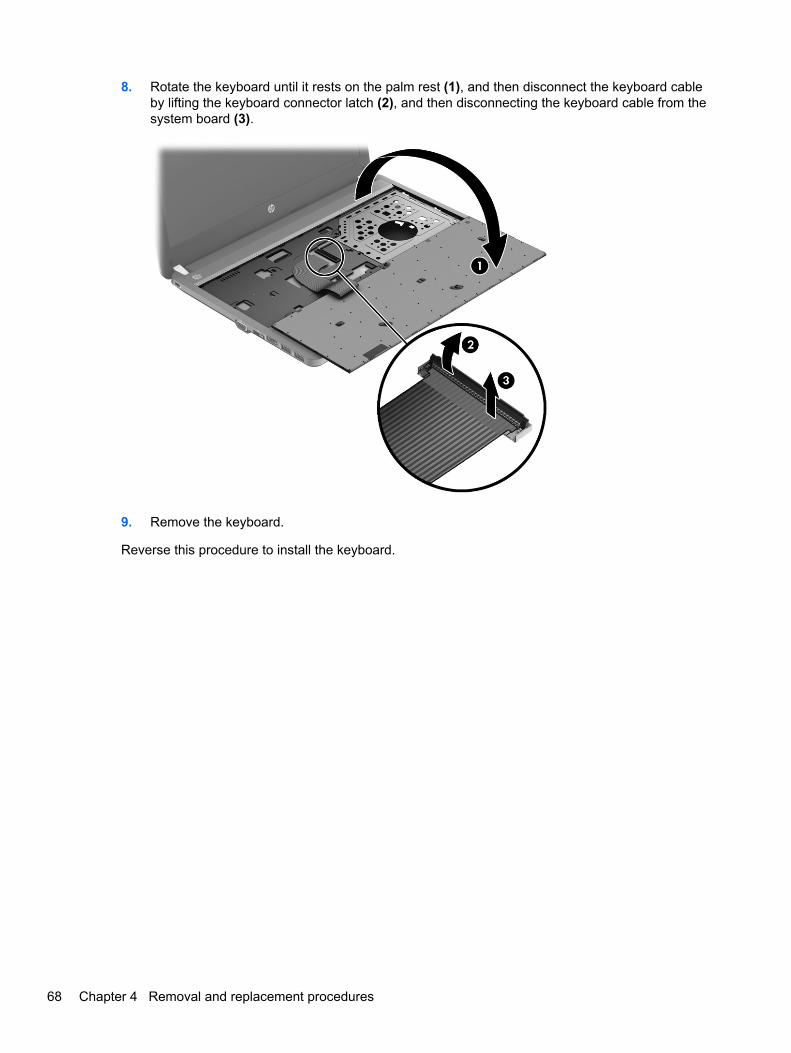
8. Rotate the keyboard until it rests on the palm rest (1), and then disconnect the keyboard cableby lifting the keyboard connector latch (2), and then disconnecting the keyboard cable from thesystem board (3).
9. Remove the keyboard.
Reverse this procedure to install the keyboard.
68 Chapter 4 Removal and replacement procedures
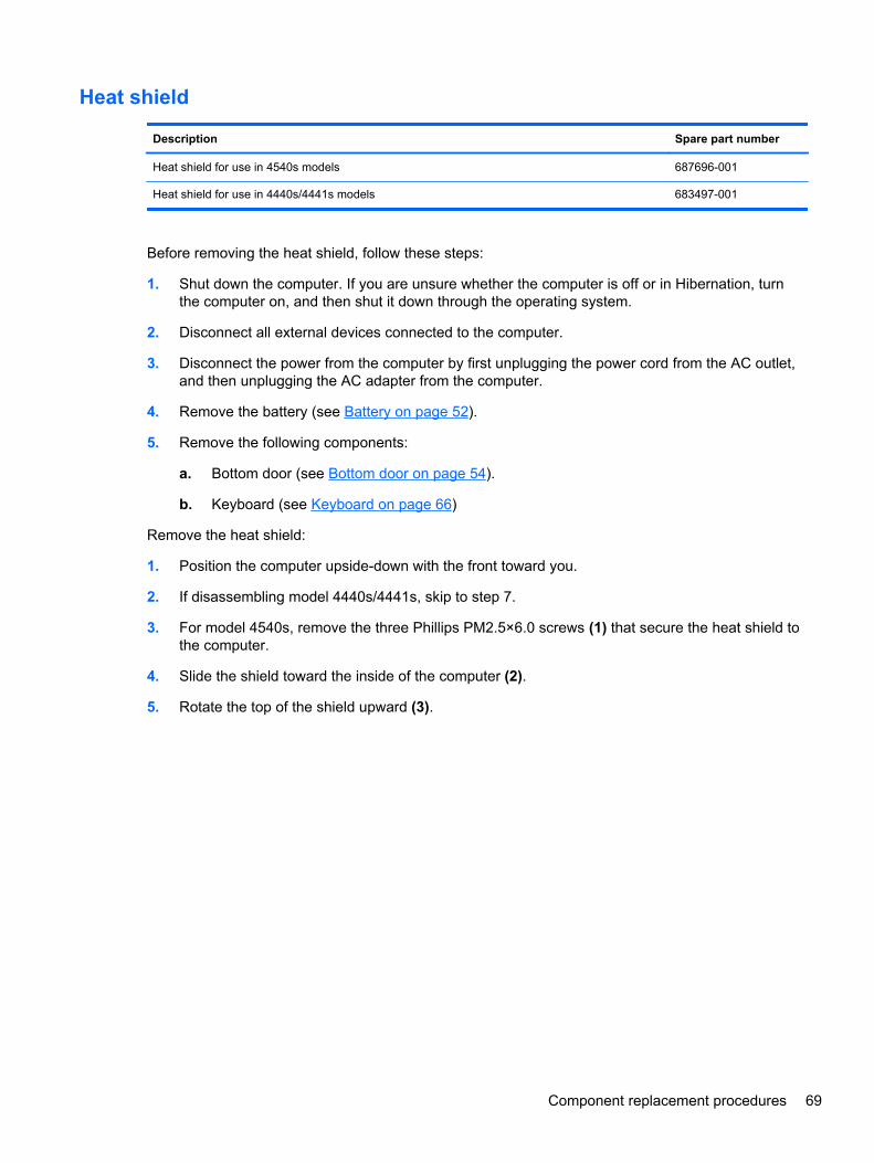
Heat shield
Description Spare part number
Heat shield for use in 4540s models 687696-001
Heat shield for use in 4440s/4441s models 683497-001
Before removing the heat shield, follow these steps:
1. Shut down the computer. If you are unsure whether the computer is off or in Hibernation, turnthe computer on, and then shut it down through the operating system.
2. Disconnect all external devices connected to the computer.
3. Disconnect the power from the computer by first unplugging the power cord from the AC outlet,and then unplugging the AC adapter from the computer.
4. Remove the battery (see Battery on page 52).
5. Remove the following components:
a. Bottom door (see Bottom door on page 54).
b. Keyboard (see Keyboard on page 66)
Remove the heat shield:
1. Position the computer upside-down with the front toward you.
2. If disassembling model 4440s/4441s, skip to step 7.
3. For model 4540s, remove the three Phillips PM2.5×6.0 screws (1) that secure the heat shield tothe computer.
4. Slide the shield toward the inside of the computer (2).
5. Rotate the top of the shield upward (3).
Component replacement procedures 69
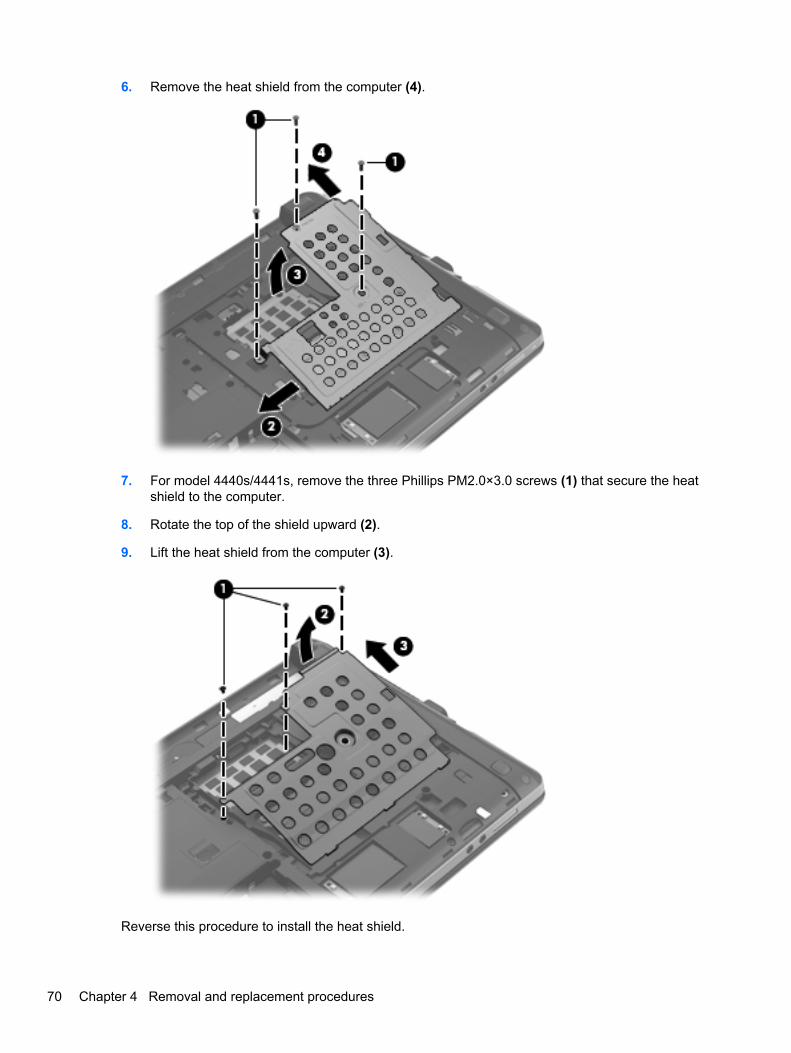
6. Remove the heat shield from the computer (4).
7. For model 4440s/4441s, remove the three Phillips PM2.0×3.0 screws (1) that secure the heatshield to the computer.
8. Rotate the top of the shield upward (2).
9. Lift the heat shield from the computer (3).
Reverse this procedure to install the heat shield.
70 Chapter 4 Removal and replacement procedures
Fan
Description Spare part number
Fan for use in 4540s models 683484-001
Fan for use in 4440s/4441s models 683651-001
Before removing the fan, follow these steps:
1. Shut down the computer. If you are unsure whether the computer is off or in Hibernation, turnthe computer on, and then shut it down through the operating system.
2. Disconnect all external devices connected to the computer.
3. Disconnect the power from the computer by first unplugging the power cord from the AC outlet,and then unplugging the AC adapter from the computer.
4. Remove the battery (see Battery on page 52).
5. Remove the following components:
a. Bottom door (see Bottom door on page 54).
b. Keyboard (see Keyboard on page 66)
c. Heat shield (see Heat shield on page 69)
Remove the fan:
1. Position the computer upside-down.
2. Disconnect the fan cable (1) from the system board.
3. Remove the two Phillips PM2.5×5.0 screws (2) that secure the fan to the system board.
Component replacement procedures 71
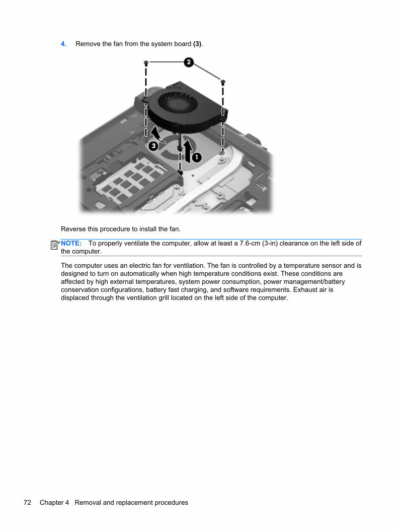
4. Remove the fan from the system board (3).
Reverse this procedure to install the fan.
NOTE: To properly ventilate the computer, allow at least a 7.6-cm (3-in) clearance on the left side ofthe computer.
The computer uses an electric fan for ventilation. The fan is controlled by a temperature sensor and isdesigned to turn on automatically when high temperature conditions exist. These conditions areaffected by high external temperatures, system power consumption, power management/batteryconservation configurations, battery fast charging, and software requirements. Exhaust air isdisplaced through the ventilation grill located on the left side of the computer.
72 Chapter 4 Removal and replacement procedures
Heat sink
All heat sink spare part kits include replacement thermal material.
Description Spare part number
For use in 4540s models:
Heat sink for use in models with UMA graphics 683489-001
Heat sink for use in models with discrete graphics 683490-001
For use in 4440s/4441s models:
Heat sink for use in models with discrete graphics 683655-001
Heat sink for use in models with UMA graphics 683656-001
Before removing the heat sink, follow these steps:
1. Shut down the computer. If you are unsure whether the computer is off or in Hibernation, turnthe computer on, and then shut it down through the operating system.
2. Disconnect all external devices connected to the computer.
3. Disconnect the power from the computer by first unplugging the power cord from the AC outlet,and then unplugging the AC adapter from the computer.
4. Remove the battery (see Battery on page 52).
5. Remove the following components:
a. Bottom door (see Bottom door on page 54).
b. Keyboard (see Keyboard on page 66)
c. Heat shield (see Heat shield on page 69)
d. Fan (see Fan on page 71)
Remove the heat sink:
1. Position the computer upside-down.
2. To remove the discrete heat sink, in the order indicated, loosen the six captive Phillips screws(1) that secure the heat sink to the system board.
Component replacement procedures 73
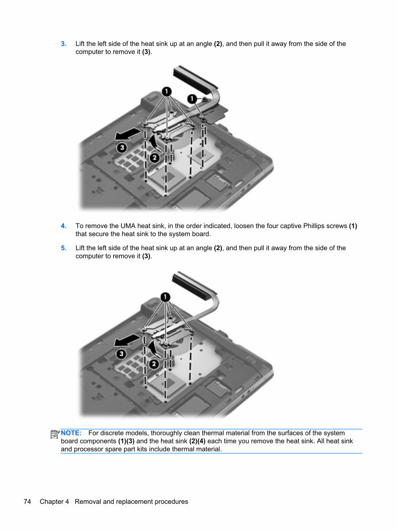
3. Lift the left side of the heat sink up at an angle (2), and then pull it away from the side of thecomputer to remove it (3).
4. To remove the UMA heat sink, in the order indicated, loosen the four captive Phillips screws (1)that secure the heat sink to the system board.
5. Lift the left side of the heat sink up at an angle (2), and then pull it away from the side of thecomputer to remove it (3).
NOTE: For discrete models, thoroughly clean thermal material from the surfaces of the systemboard components (1)(3) and the heat sink (2)(4) each time you remove the heat sink. All heat sinkand processor spare part kits include thermal material.
74 Chapter 4 Removal and replacement procedures
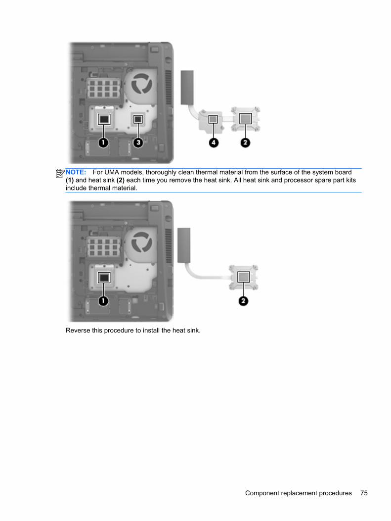
NOTE: For UMA models, thoroughly clean thermal material from the surface of the system board(1) and heat sink (2) each time you remove the heat sink. All heat sink and processor spare part kitsinclude thermal material.
Reverse this procedure to install the heat sink.
Component replacement procedures 75
Processor
NOTE: All processor spare part kits include replacement thermal material.
Description Spare part number
Intel Core i7 processor, Quad Core:
3632QM, 2.2-GHz processor with 6-MB L3 cache 701658-001
3612QM, 2.1-GHz processor with 6-MB L3 cache 680647-001
Intel Core i5 processors, Dual Core:
3360M, 2.8-GHz processor with 3-MB L3 cache 681953-001
3320M, 2.6-GHz processor with 3-MB L3 cache 681952-001
2450M, 2.5-GHz processor with 3-MB L3 cache 676359-001
Intel Core i3 processors, Dual Core:
3120M, 2.5-GHz processor with 3-MB L3 cache 700627-001
3110M, 2.3-GHz processor with 3-MB L3 cache 682417-001
2370M, 2.4-GHz processor with 3-MB L3 cache 677152-001
2350M, 2.3-GHz processor with 3-MB L3 cache 653340-001
Intel Pentium processor, Dual Core:
2020M, 2.4-GHz, with 2-MB L3 cache 700628-001
B980, 2.4-GHz, with 2-MB L3 cache 692428-001
B970, 2.3-GHz, with 2-MB L3 cache 676785-001
Intel Celeron processor:
B840, 1.9-GHz, with 2-MB L3 cache 664663-001
Before removing the processor, follow these steps:
1. Shut down the computer. If you are unsure whether the computer is off or in Hibernation, turnthe computer on, and then shut it down through the operating system.
2. Disconnect all external devices connected to the computer.
3. Disconnect the power from the computer by first unplugging the power cord from the AC outlet,and then unplugging the AC adapter from the computer.
4. Remove the battery (see Battery on page 52).
5. Remove the following components:
a. Bottom door (see Bottom door on page 54).
b. Keyboard (see Keyboard on page 66)
c. Heat shield (see Heat shield on page 69)
76 Chapter 4 Removal and replacement procedures
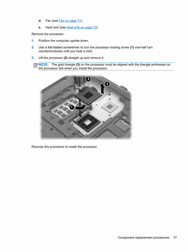
d. Fan (see Fan on page 71)
e. Heat sink (see Heat sink on page 73)
Remove the processor:
1. Position the computer upside-down.
2. Use a flat-bladed screwdriver to turn the processor locking screw (1) one-half turncounterclockwise until you hear a click.
3. Lift the processor (2) straight up and remove it.
NOTE: The gold triangle (3) on the processor must be aligned with the triangle embossed onthe processor slot when you install the processor.
Reverse this procedure to install the processor.
Component replacement procedures 77
Top cover
NOTE: All top covers include the touchpad assembly.
Description Spare part number
Top cover for use in model 4540s:
With a fingerprint reader 683506-001
Without a fingerprint reader 683507-001
For use in model 4440s/4441s:
With a fingerprint reader 683666-001
Without a fingerprint reader 683667-001
Before removing the top cover, follow these steps:
1. Shut down the computer. If you are unsure whether the computer is off or in Hibernation, turnthe computer on, and then shut it down through the operating system.
2. Disconnect all external devices connected to the computer.
3. Disconnect the power from the computer by first unplugging the power cord from the AC outlet,and then unplugging the AC adapter from the computer.
4. Remove the battery (see Battery on page 52).
5. Remove the following components:
a. Bottom door (see Bottom door on page 54).
b. Memory modules (see Memory modules on page 60)
c. WLAN/Bluetooth module (see WLAN/Bluetooth combo card on page 64)
d. WWAN module (see WWAN module on page 62)
e. Keyboard (see Keyboard on page 66)
f. Heat shield (see Heat shield on page 69)
Remove the top cover:
1. Position the computer upright with the front toward you.
78 Chapter 4 Removal and replacement procedures
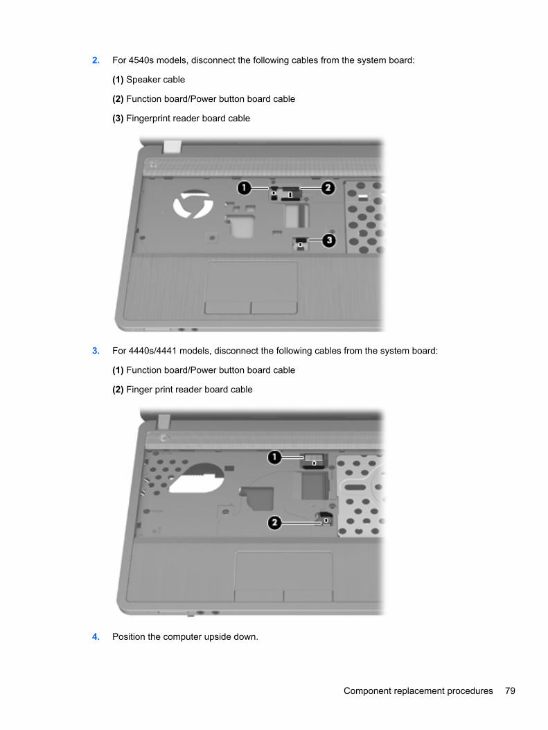
2. For 4540s models, disconnect the following cables from the system board:
(1) Speaker cable
(2) Function board/Power button board cable
(3) Fingerprint reader board cable
3. For 4440s/4441 models, disconnect the following cables from the system board:
(1) Function board/Power button board cable
(2) Finger print reader board cable
4. Position the computer upside down.
Component replacement procedures 79

5. For 4540s models, remove the following screws that secure the top cover to the computer:
(1) 4 rubber screw covers from the corners of the computer
(2) 11 Torx T8M2.5×6.0 screws
80 Chapter 4 Removal and replacement procedures
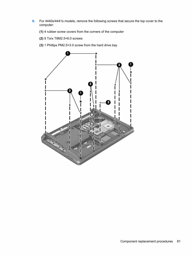
6. For 4440s/4441s models, remove the following screws that secure the top cover to thecomputer:
(1) 4 rubber screw covers from the corners of the computer
(2) 9 Torx T8M2.5×6.0 screws
(3) 1 Phillips PM2.5×3.0 screw from the hard drive bay
Component replacement procedures 81
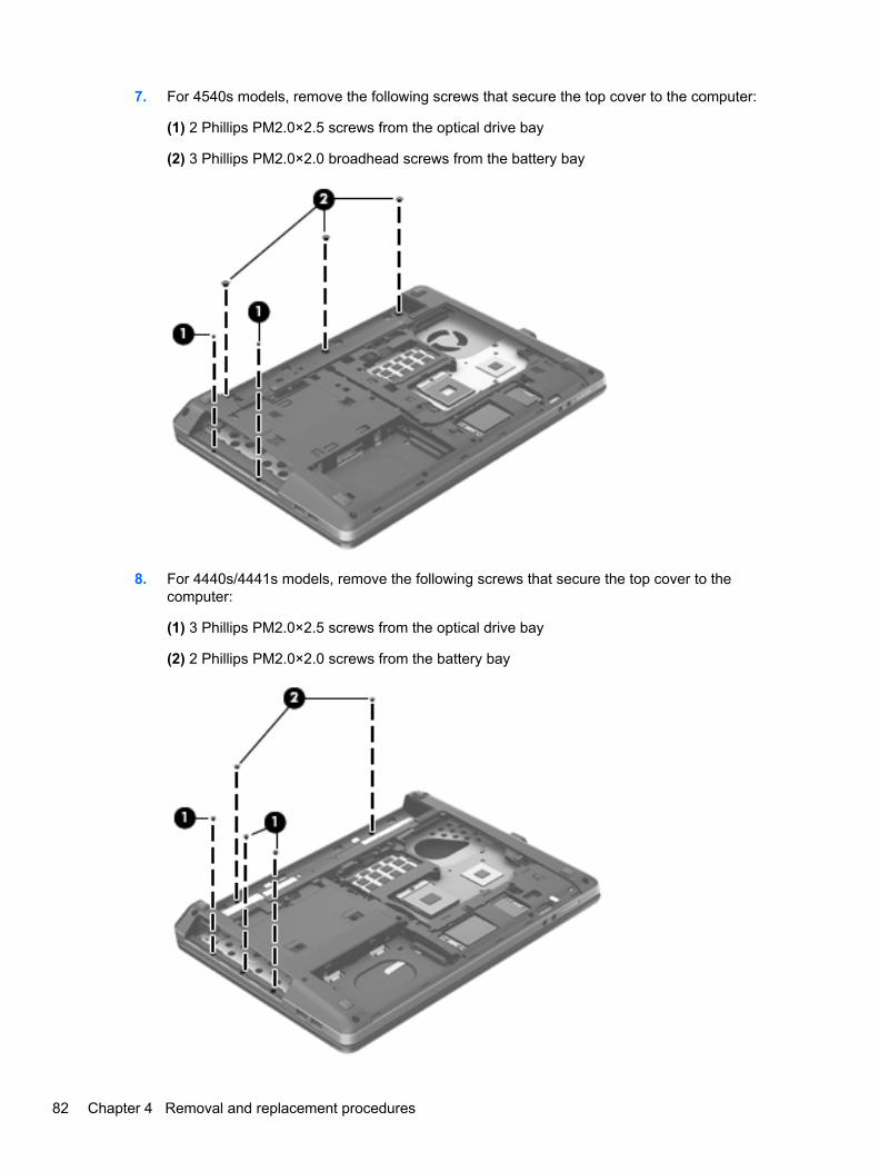
7. For 4540s models, remove the following screws that secure the top cover to the computer:
(1) 2 Phillips PM2.0×2.5 screws from the optical drive bay
(2) 3 Phillips PM2.0×2.0 broadhead screws from the battery bay
8. For 4440s/4441s models, remove the following screws that secure the top cover to thecomputer:
(1) 3 Phillips PM2.0×2.5 screws from the optical drive bay
(2) 2 Phillips PM2.0×2.0 screws from the battery bay
82 Chapter 4 Removal and replacement procedures
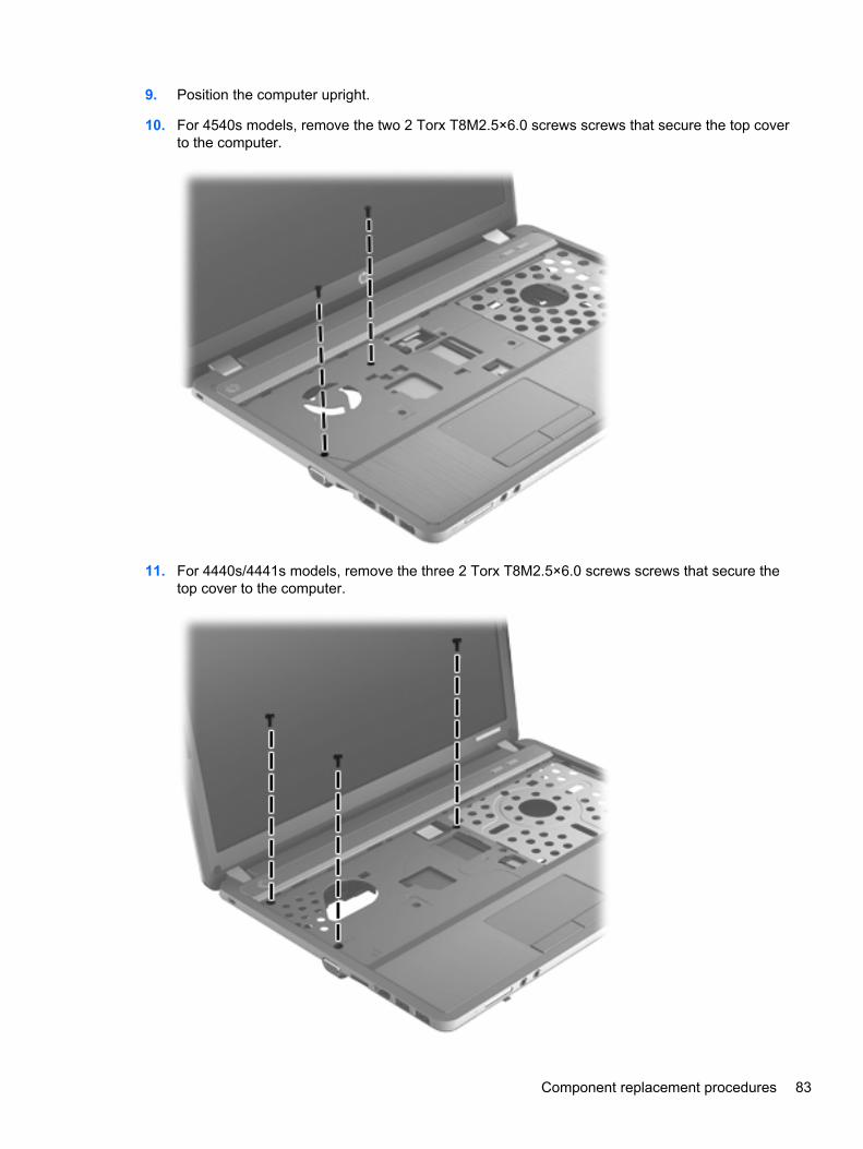
9. Position the computer upright.
10. For 4540s models, remove the two 2 Torx T8M2.5×6.0 screws screws that secure the top coverto the computer.
11. For 4440s/4441s models, remove the three 2 Torx T8M2.5×6.0 screws screws that secure thetop cover to the computer.
Component replacement procedures 83
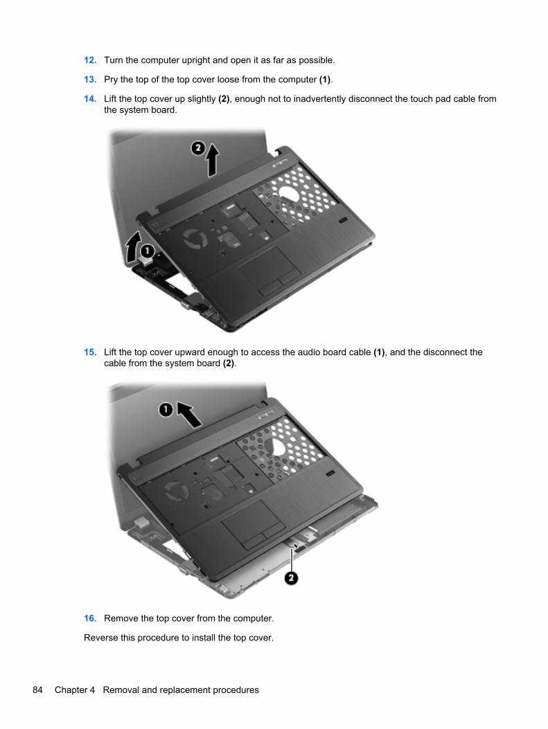
12. Turn the computer upright and open it as far as possible.
13. Pry the top of the top cover loose from the computer (1).
14. Lift the top cover up slightly (2), enough not to inadvertently disconnect the touch pad cable fromthe system board.
15. Lift the top cover upward enough to access the audio board cable (1), and the disconnect thecable from the system board (2).
16. Remove the top cover from the computer.
Reverse this procedure to install the top cover.
84 Chapter 4 Removal and replacement procedures
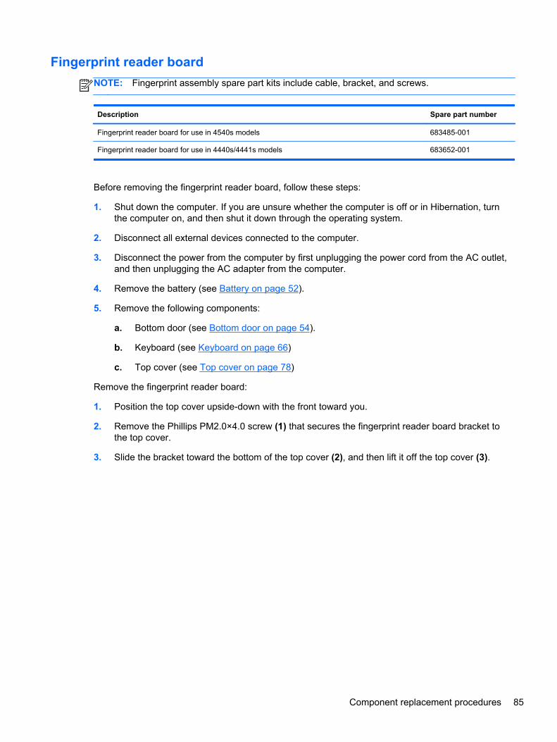
Fingerprint reader board
NOTE: Fingerprint assembly spare part kits include cable, bracket, and screws.
Description Spare part number
Fingerprint reader board for use in 4540s models 683485-001
Fingerprint reader board for use in 4440s/4441s models 683652-001
Before removing the fingerprint reader board, follow these steps:
1. Shut down the computer. If you are unsure whether the computer is off or in Hibernation, turnthe computer on, and then shut it down through the operating system.
2. Disconnect all external devices connected to the computer.
3. Disconnect the power from the computer by first unplugging the power cord from the AC outlet,and then unplugging the AC adapter from the computer.
4. Remove the battery (see Battery on page 52).
5. Remove the following components:
a. Bottom door (see Bottom door on page 54).
b. Keyboard (see Keyboard on page 66)
c. Top cover (see Top cover on page 78)
Remove the fingerprint reader board:
1. Position the top cover upside-down with the front toward you.
2. Remove the Phillips PM2.0×4.0 screw (1) that secures the fingerprint reader board bracket tothe top cover.
3. Slide the bracket toward the bottom of the top cover (2), and then lift it off the top cover (3).
Component replacement procedures 85

4. Remove the reader and cable assembly from the top cover (4).
Reverse this procedure to install the fingerprint reader board.
86 Chapter 4 Removal and replacement procedures
Speaker assembly
NOTE: In 4540s models, the speakers are mounted to the bottom of the top cover.
NOTE: In 4440s/4441s models, the speakers are mounted to the base enclosure.
Description Spare part number
Speaker assembly for use in 4540s models 683505-001
Speaker assembly for use in 4440s/4441s models 683665-001
Before removing the speaker assembly, follow these steps:
1. Shut down the computer. If you are unsure whether the computer is off or in Hibernation, turnthe computer on, and then shut it down through the operating system.
2. Disconnect all external devices connected to the computer.
3. Disconnect the power from the computer by first unplugging the power cord from the AC outlet,and then unplugging the AC adapter from the computer.
4. Remove the battery (see Battery on page 52).
5. Remove the following components:
a. Bottom door (see Bottom door on page 54).
b. Keyboard (see Keyboard on page 66)
c. Top cover (see Top cover on page 78)
Remove the speaker assembly:
1. If disassembling model 4440s/4441s, skip to step 7.
2. Position the top cover upside-down with the front toward you.
3. For model 4540s, disconnect the speaker cable from the system board (1) and remove thecables from under the power button board cable and from the clips.
4. Remove the cables from under the power button board cable and from the clips.
5. Remove the two Phillips PM2.0×7.0 screws (2) that secure the speakers to the computer.
Component replacement procedures 87
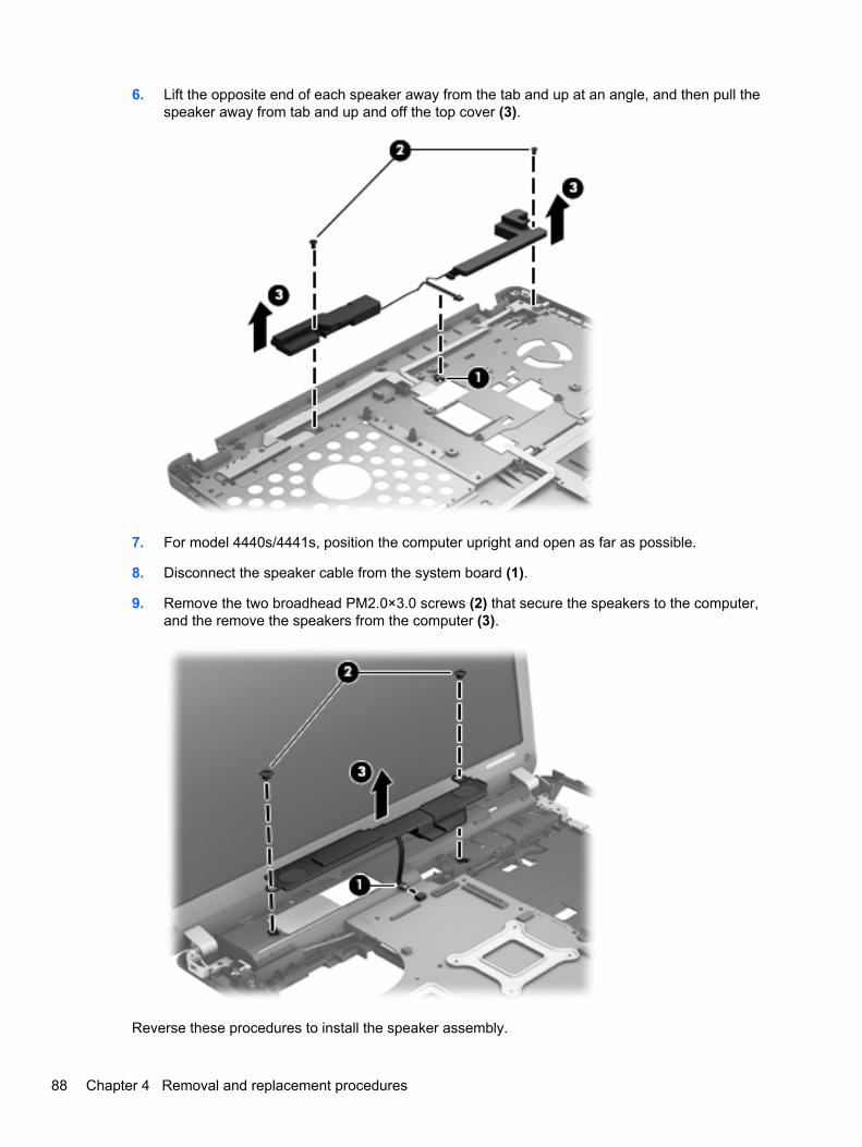
6. Lift the opposite end of each speaker away from the tab and up at an angle, and then pull thespeaker away from tab and up and off the top cover (3).
7. For model 4440s/4441s, position the computer upright and open as far as possible.
8. Disconnect the speaker cable from the system board (1).
9. Remove the two broadhead PM2.0×3.0 screws (2) that secure the speakers to the computer,and the remove the speakers from the computer (3).
Reverse these procedures to install the speaker assembly.
88 Chapter 4 Removal and replacement procedures
Function board/Power button board assembly
Description Spare part number
Function board/Power button board assembly for use in 4540s models (includes cable) 683486-001
Function board/Power button board for use in 4440s/4441s models (includes cable) 683653-001
Before removing the function board and power button board, follow these steps:
1. Shut down the computer. If you are unsure whether the computer is off or in Hibernation, turnthe computer on, and then shut it down through the operating system.
2. Disconnect all external devices connected to the computer.
3. Disconnect the power from the computer by first unplugging the power cord from the AC outlet,and then unplugging the AC adapter from the computer.
4. Remove the battery (see Battery on page 52).
5. Remove the following components:
a. Bottom door (see Bottom door on page 54).
b. Keyboard (see Keyboard on page 66)
c. Top cover (see Top cover on page 78)
d. Speaker (see Speaker assembly on page 87)
Remove the function board/power button board assembly:
1. Position the top cover upside-down with the front toward you.
2. Remove the two Phillips PM2.0×4.0 screws (1) that secure the boards to the top cover.
3. Remove the function board from the top cover (2).
Component replacement procedures 89
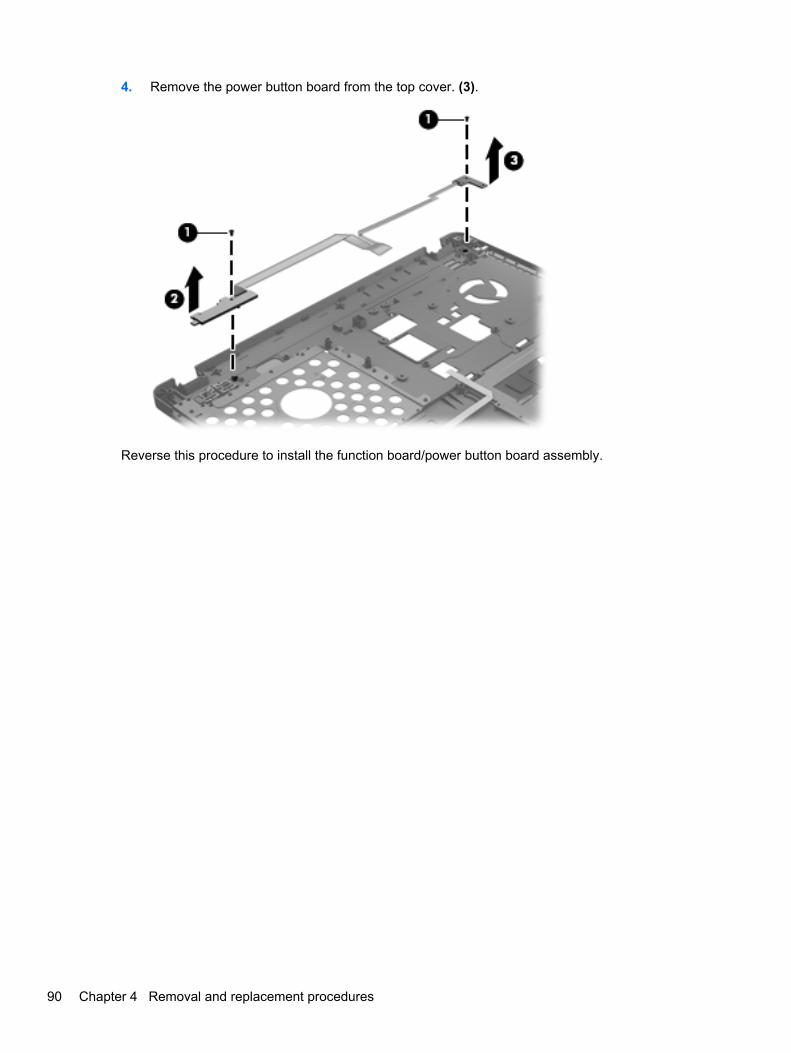
4. Remove the power button board from the top cover. (3).
Reverse this procedure to install the function board/power button board assembly.
90 Chapter 4 Removal and replacement procedures
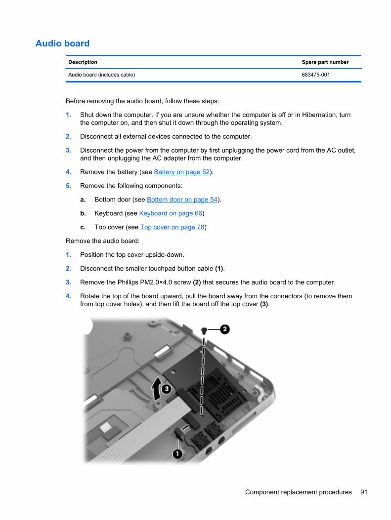
Audio board
Description Spare part number
Audio board (includes cable) 683475-001
Before removing the audio board, follow these steps:
1. Shut down the computer. If you are unsure whether the computer is off or in Hibernation, turnthe computer on, and then shut it down through the operating system.
2. Disconnect all external devices connected to the computer.
3. Disconnect the power from the computer by first unplugging the power cord from the AC outlet,and then unplugging the AC adapter from the computer.
4. Remove the battery (see Battery on page 52).
5. Remove the following components:
a. Bottom door (see Bottom door on page 54).
b. Keyboard (see Keyboard on page 66)
c. Top cover (see Top cover on page 78)
Remove the audio board:
1. Position the top cover upside-down.
2. Disconnect the smaller touchpad button cable (1).
3. Remove the Phillips PM2.0×4.0 screw (2) that secures the audio board to the computer.
4. Rotate the top of the board upward, pull the board away from the connectors (to remove themfrom top cover holes), and then lift the board off the top cover (3).
Component replacement procedures 91
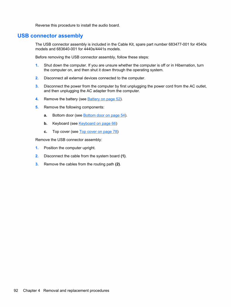
Reverse this procedure to install the audio board.
USB connector assembly
The USB connector assembly is included in the Cable Kit, spare part number 683477-001 for 4540smodels and 683640-001 for 4440s/4441s models.
Before removing the USB connector assembly, follow these steps:
1. Shut down the computer. If you are unsure whether the computer is off or in Hibernation, turnthe computer on, and then shut it down through the operating system.
2. Disconnect all external devices connected to the computer.
3. Disconnect the power from the computer by first unplugging the power cord from the AC outlet,and then unplugging the AC adapter from the computer.
4. Remove the battery (see Battery on page 52).
5. Remove the following components:
a. Bottom door (see Bottom door on page 54).
b. Keyboard (see Keyboard on page 66)
c. Top cover (see Top cover on page 78)
Remove the USB connector assembly:
1. Position the computer upright.
2. Disconnect the cable from the system board (1).
3. Remove the cables from the routing path (2).
92 Chapter 4 Removal and replacement procedures
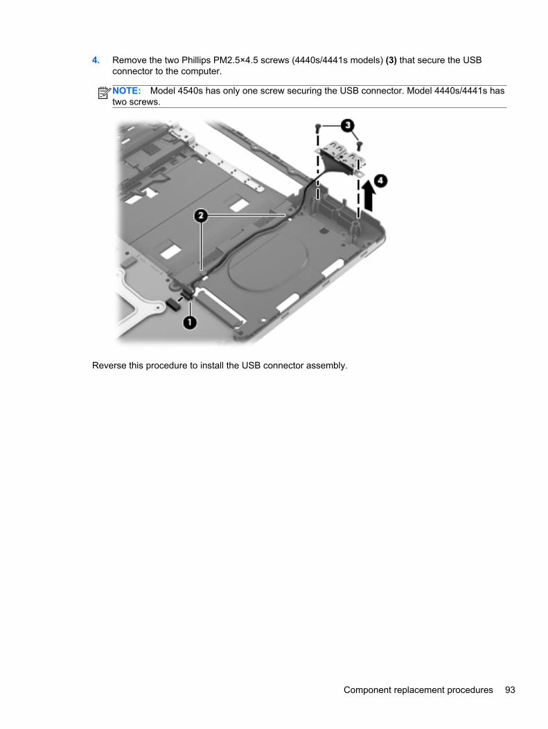
4. Remove the two Phillips PM2.5×4.5 screws (4440s/4441s models) (3) that secure the USBconnector to the computer.
NOTE: Model 4540s has only one screw securing the USB connector. Model 4440s/4441s hastwo screws.
Reverse this procedure to install the USB connector assembly.
Component replacement procedures 93
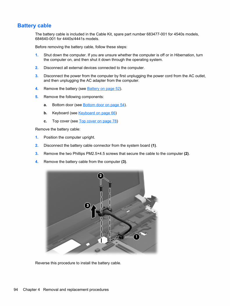
Battery cable
The battery cable is included in the Cable Kit, spare part number 683477-001 for 4540s models,684640-001 for 4440s/4441s models.
Before removing the battery cable, follow these steps:
1. Shut down the computer. If you are unsure whether the computer is off or in Hibernation, turnthe computer on, and then shut it down through the operating system.
2. Disconnect all external devices connected to the computer.
3. Disconnect the power from the computer by first unplugging the power cord from the AC outlet,and then unplugging the AC adapter from the computer.
4. Remove the battery (see Battery on page 52).
5. Remove the following components:
a. Bottom door (see Bottom door on page 54).
b. Keyboard (see Keyboard on page 66)
c. Top cover (see Top cover on page 78)
Remove the battery cable:
1. Position the computer upright.
2. Disconnect the battery cable connector from the system board (1).
3. Remove the two Phillips PM2.5×4.5 screws that secure the cable to the computer (2).
4. Remove the battery cable from the computer (3).
Reverse this procedure to install the battery cable.
94 Chapter 4 Removal and replacement procedures
System board
NOTE: All system board spare part kits include replacement thermal material.
Description Spare part number
System board for use in models without Windows 8:
UMA graphics with WWAN 683496-001
UMA graphics without WWAN 683495-001
1-GB of discrete graphics memory 683493-001
2-GB of discrete graphics memory 683494-001
System board for use in models with Windows 8:
Windows 8 Standard and UMA graphics with WWAN 683496-501
Windows 8 Professional and UMA graphics with WWAN 683496-601
Windows 8 Standard and UMA graphics without WWAN 683495-501
Windows 8 Professional and UMA graphics without WWAN 683495-601
Windows 8 Standard and 1-GB discrete graphics memory 683493-601
Windows 8 Professional and 1-GB discrete graphics memory 683493-601
Windows 8 Standard and 2-GB discrete graphics memory 683494-601
Windows 8 Professional and 2-GB discrete graphics memory 683494-601
Before removing the system board, follow these steps:
1. Shut down the computer. If you are unsure whether the computer is off or in Hibernation, turnthe computer on, and then shut it down through the operating system.
2. Disconnect all external devices connected to the computer.
3. Disconnect the power from the computer by first unplugging the power cord from the AC outlet,and then unplugging the AC adapter from the computer.
4. Remove the battery (see Battery on page 52).
5. Remove the following components:
a. Bottom door (see Bottom door on page 54).
b. Hard drive (see Hard drive on page 58)
c. Optical drive (see Optical drive on page 56)
d. Keyboard (see Keyboard on page 66)
e. Heat shield (see Heat shield on page 69)
f. Fan (see Fan on page 71)
Component replacement procedures 95
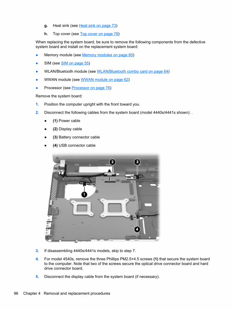
g. Heat sink (see Heat sink on page 73)
h. Top cover (see Top cover on page 78)
When replacing the system board, be sure to remove the following components from the defectivesystem board and install on the replacement system board:
● Memory module (see Memory modules on page 60)
● SIM (see SIM on page 55)
● WLAN/Bluetooth module (see WLAN/Bluetooth combo card on page 64)
● WWAN module (see WWAN module on page 62)
● Processor (see Processor on page 76)
Remove the system board:
1. Position the computer upright with the front toward you.
2. Disconnect the following cables from the system board (model 4440s/4441s shown): .
● (1) Power cable
● (2) Display cable
● (3) Battery connector cable
● (4) USB connector cable
3. If disassembling 4440s/4441s models, skip to step 7.
4. For model 4540s, remove the three Phillips PM2.5×4.5 screws (1) that secure the system boardto the computer. Note that two of the screws secure the optical drive connector board and harddrive connector board.
5. Disconnect the display cable from the system board (if necessary).
96 Chapter 4 Removal and replacement procedures
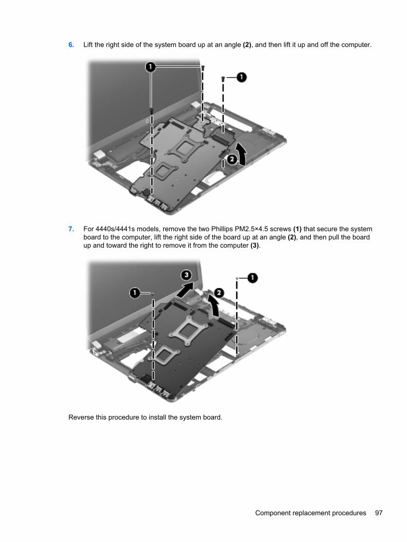
6. Lift the right side of the system board up at an angle (2), and then lift it up and off the computer.
7. For 4440s/4441s models, remove the two Phillips PM2.5×4.5 screws (1) that secure the systemboard to the computer, lift the right side of the board up at an angle (2), and then pull the boardup and toward the right to remove it from the computer (3).
Reverse this procedure to install the system board.
Component replacement procedures 97
RTC battery
Description Spare part number
RTC battery 683502-001
Before removing the RTC battery, follow these steps:
1. Shut down the computer. If you are unsure whether the computer is off or in Hibernation, turnthe computer on, and then shut it down through the operating system.
2. Disconnect all external devices connected to the computer.
3. Disconnect the power from the computer by first unplugging the power cord from the AC outlet,and then unplugging the AC adapter from the computer.
4. Remove the battery (see Battery on page 52).
5. Remove the following components:
a. Bottom door (see Bottom door on page 54).
b. Hard drive (see Hard drive on page 58)
c. Optical drive (see Optical drive on page 56)
d. Keyboard (see Keyboard on page 66)
e. Heat shield (see Heat shield on page 69)
f. Fan (see Fan on page 71)
g. Heat sink (see Heat sink on page 73)
h. Top cover (see Top cover on page 78)
i. System board (see System board on page 95)
Remove the RTC battery:
1. Position the system board upside-down.
2. Disconnect the battery cable from the system board (1).
98 Chapter 4 Removal and replacement procedures
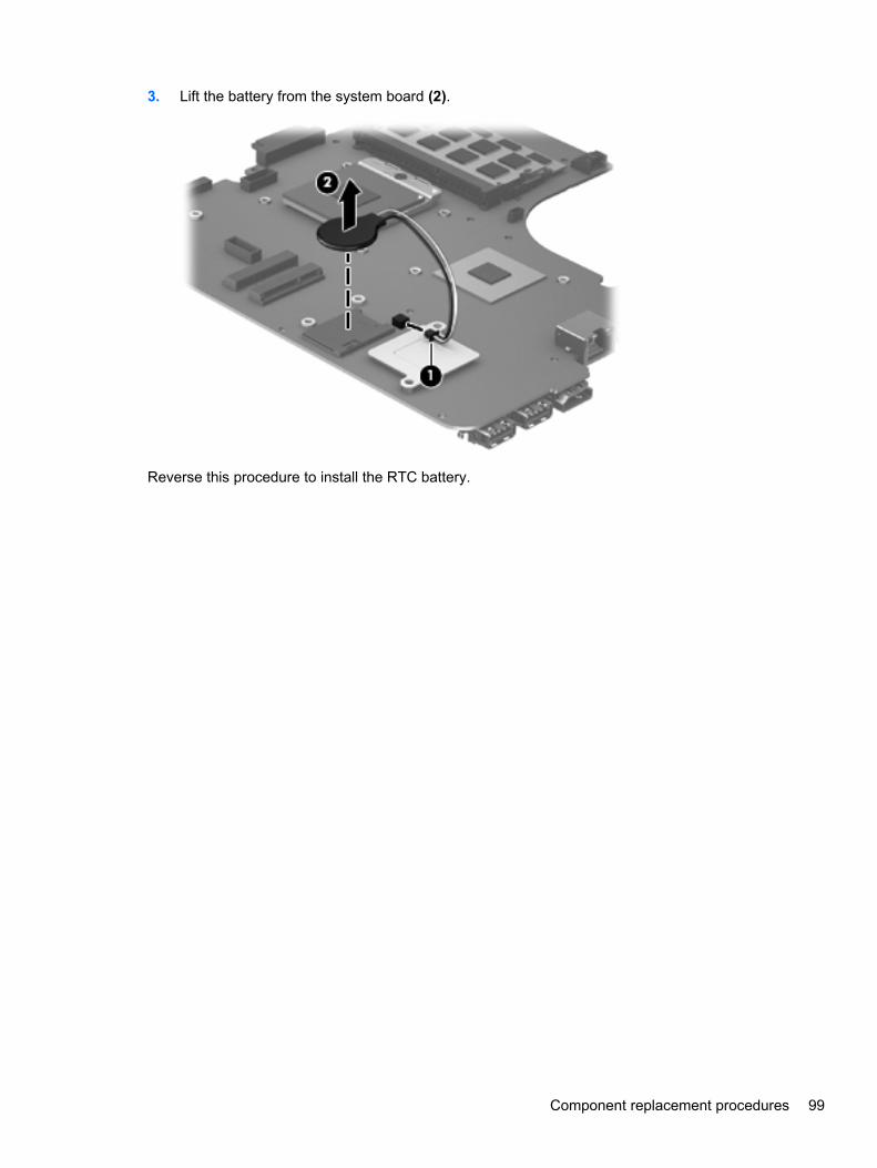
3. Lift the battery from the system board (2).
Reverse this procedure to install the RTC battery.
Component replacement procedures 99
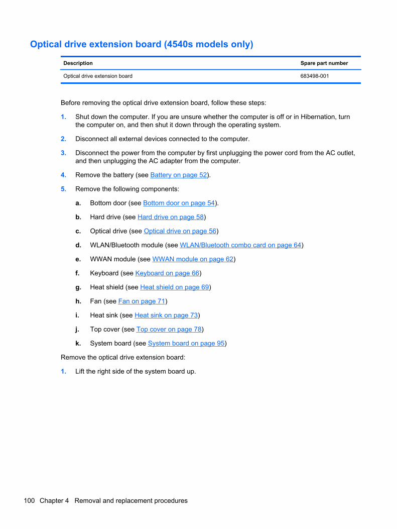
Optical drive extension board (4540s models only)
Description Spare part number
Optical drive extension board 683498-001
Before removing the optical drive extension board, follow these steps:
1. Shut down the computer. If you are unsure whether the computer is off or in Hibernation, turnthe computer on, and then shut it down through the operating system.
2. Disconnect all external devices connected to the computer.
3. Disconnect the power from the computer by first unplugging the power cord from the AC outlet,and then unplugging the AC adapter from the computer.
4. Remove the battery (see Battery on page 52).
5. Remove the following components:
a. Bottom door (see Bottom door on page 54).
b. Hard drive (see Hard drive on page 58)
c. Optical drive (see Optical drive on page 56)
d. WLAN/Bluetooth module (see WLAN/Bluetooth combo card on page 64)
e. WWAN module (see WWAN module on page 62)
f. Keyboard (see Keyboard on page 66)
g. Heat shield (see Heat shield on page 69)
h. Fan (see Fan on page 71)
i. Heat sink (see Heat sink on page 73)
j. Top cover (see Top cover on page 78)
k. System board (see System board on page 95)
Remove the optical drive extension board:
1. Lift the right side of the system board up.
100 Chapter 4 Removal and replacement procedures
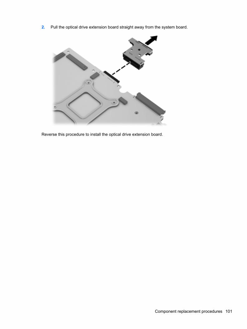
2. Pull the optical drive extension board straight away from the system board.
Reverse this procedure to install the optical drive extension board.
Component replacement procedures 101
Hard drive extension board (4540s models only)
Description Spare part number
Hard drive extension board 683487-001
Before removing the hard drive extension board, follow these steps:
1. Shut down the computer. If you are unsure whether the computer is off or in Hibernation, turnthe computer on, and then shut it down through the operating system.
2. Disconnect all external devices connected to the computer.
3. Disconnect the power from the computer by first unplugging the power cord from the AC outlet,and then unplugging the AC adapter from the computer.
4. Remove the battery (see Battery on page 52).
5. Remove the following components:
a. Bottom door (see Bottom door on page 54).
b. Hard drive (see Hard drive on page 58)
c. Optical drive (see Optical drive on page 56)
d. WLAN/Bluetooth module (see WLAN/Bluetooth combo card on page 64)
e. WWAN module (see WWAN module on page 62)
f. Keyboard (see Keyboard on page 66)
g. Heat shield (see Heat shield on page 69)
h. Fan (see Fan on page 71)
i. Heat sink (see Heat sink on page 73)
j. Top cover (see Top cover on page 78)
k. System board (see System board on page 95)
Remove the hard drive extension board:
1. Lift the right side of the system board up.
102 Chapter 4 Removal and replacement procedures
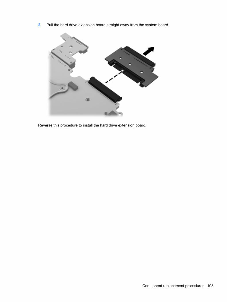
2. Pull the hard drive extension board straight away from the system board.
Reverse this procedure to install the hard drive extension board.
Component replacement procedures 103
Power cable
The power cable is included in the Cable Kit, spare part number 683477-001 for 4540s models,683640-001 for 4440s/4441s models.
Before removing the power cable, follow these steps:
1. Shut down the computer. If you are unsure whether the computer is off or in Hibernation, turnthe computer on, and then shut it down through the operating system.
2. Disconnect all external devices connected to the computer.
3. Disconnect the power from the computer by first unplugging the power cord from the AC outlet,and then unplugging the AC adapter from the computer.
4. Remove the battery (see Battery on page 52).
5. Remove the following components:
a. Bottom door (see Bottom door on page 54).
b. Optical drive (see Optical drive on page 56)
c. WLAN/Bluetooth module (see WLAN/Bluetooth combo card on page 64)
d. WWAN module (see WWAN module on page 62)
e. Keyboard (see Keyboard on page 66)
f. Top cover (see Top cover on page 78)
g. Speaker assembly (see Speaker assembly on page 87)
h. System board (see System board on page 95)
Remove the power cable:
1. Position the computer upright with the front toward you.
2. If necessary, disconnect the cable from the bottom of the system board (1).
104 Chapter 4 Removal and replacement procedures
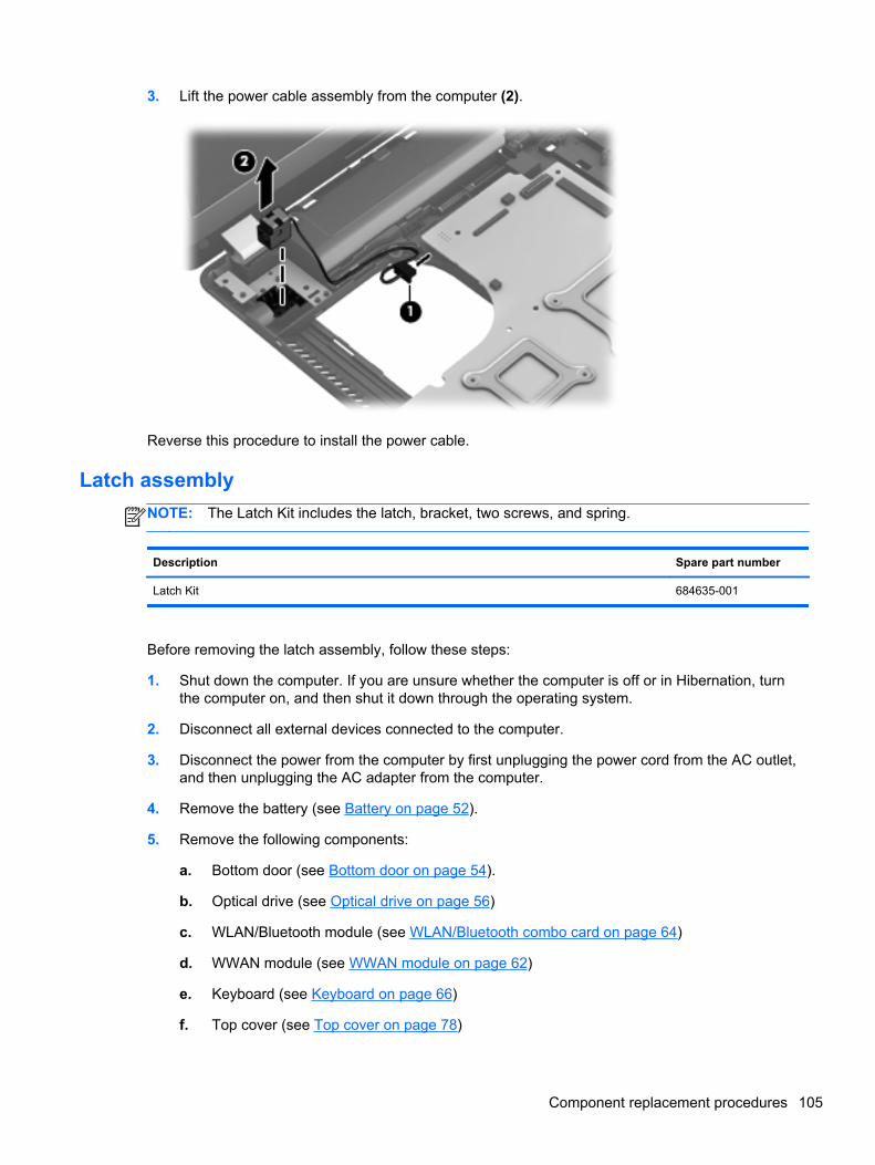
3. Lift the power cable assembly from the computer (2).
Reverse this procedure to install the power cable.
Latch assembly
NOTE: The Latch Kit includes the latch, bracket, two screws, and spring.
Description Spare part number
Latch Kit 684635-001
Before removing the latch assembly, follow these steps:
1. Shut down the computer. If you are unsure whether the computer is off or in Hibernation, turnthe computer on, and then shut it down through the operating system.
2. Disconnect all external devices connected to the computer.
3. Disconnect the power from the computer by first unplugging the power cord from the AC outlet,and then unplugging the AC adapter from the computer.
4. Remove the battery (see Battery on page 52).
5. Remove the following components:
a. Bottom door (see Bottom door on page 54).
b. Optical drive (see Optical drive on page 56)
c. WLAN/Bluetooth module (see WLAN/Bluetooth combo card on page 64)
d. WWAN module (see WWAN module on page 62)
e. Keyboard (see Keyboard on page 66)
f. Top cover (see Top cover on page 78)
Component replacement procedures 105

g. Speaker assembly (see Speaker assembly on page 87)
h. System board (see System board on page 95)
NOTE: The latch mechanism includes a small spring. Note the location of the spring.
Remove the latch assembly:
1. Position the computer right-side up, with the front toward you.
2. Slide the latch toward the left (1).
3. Lift the latch from the tab that holds it in place (2).
4. Rotate the latch up and lift it out of the computer (3).
Reverse this procedure to install the latch assembly.
106 Chapter 4 Removal and replacement procedures
Display assembly
All display assemblies include WLAN antenna transceivers and cables. WWAN models include 2WWAN antenna transceivers and cables.
For a list of individual display spare parts, see Display components on page 34.
Description Spare part number
For use in silver HP ProBook 4540s models:
● 39.6-cm (15.6-inch) HD, anti-glare, without webcam 683481-001
● 39.6-cm (15.6-inch) HD, anti-glare, with webcam 683482-001
● 39.6-cm (15.6-inch) HD, anti-glare, with webcam and WWAN 683483-001
For use in HP ProBook 4440s/4441s models:
● 35.6-cm (14.0-inch), Anti-glare, without webcam 683644-001
● 35.6-cm (14.0-inch), Anti-glare, with webcam 683645-001
● 35.6-cm (14.0-inch), Anti-glare, with webcam and WWAN 683646-001
● 35.6-cm (14.0-inch), BrightView, without webcam 683647-001
● 35.6-cm (14.0-inch), BrightView, with webcam 683648-001
● 35.6-cm (14.0-inch), BrightView, with webcam and WWAN 683650-001
Before removing the display assembly, follow these steps:
1. Shut down the computer. If you are unsure whether the computer is off or in Hibernation, turnthe computer on, and then shut it down through the operating system.
2. Disconnect all external devices connected to the computer.
3. Disconnect the power from the computer by first unplugging the power cord from the AC outlet,and then unplugging the AC adapter from the computer.
4. Remove the battery (see Battery on page 52).
5. Remove the following components:
a. Bottom door (see Bottom door on page 54).
b. WLAN module (see WLAN/Bluetooth combo card on page 64)
c. WWAN module (see WWAN module on page 62)
d. Keyboard (see Keyboard on page 66)
e. Top cover (see Top cover on page 78)
Remove the display assembly:
1. Position the computer upright with the front toward you.
2. Open the computer as far as possible.
3. If necessary, disconnect the display cable from the system board.
Component replacement procedures 107
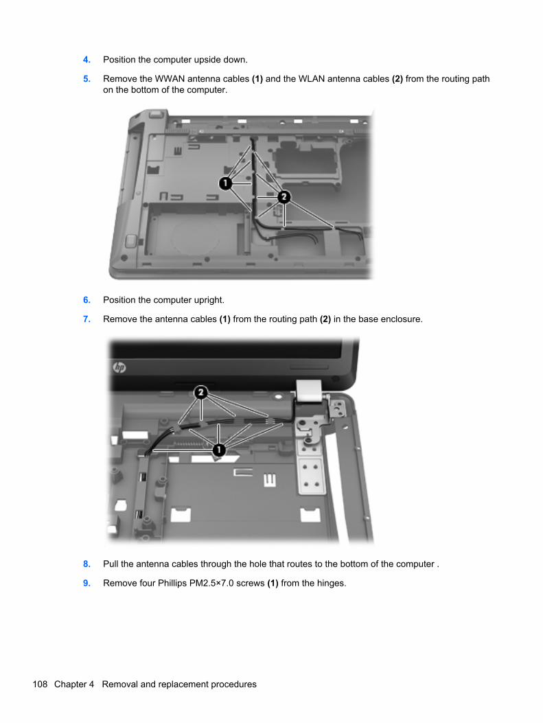
4. Position the computer upside down.
5. Remove the WWAN antenna cables (1) and the WLAN antenna cables (2) from the routing pathon the bottom of the computer.
6. Position the computer upright.
7. Remove the antenna cables (1) from the routing path (2) in the base enclosure.
8. Pull the antenna cables through the hole that routes to the bottom of the computer .
9. Remove four Phillips PM2.5×7.0 screws (1) from the hinges.
108 Chapter 4 Removal and replacement procedures
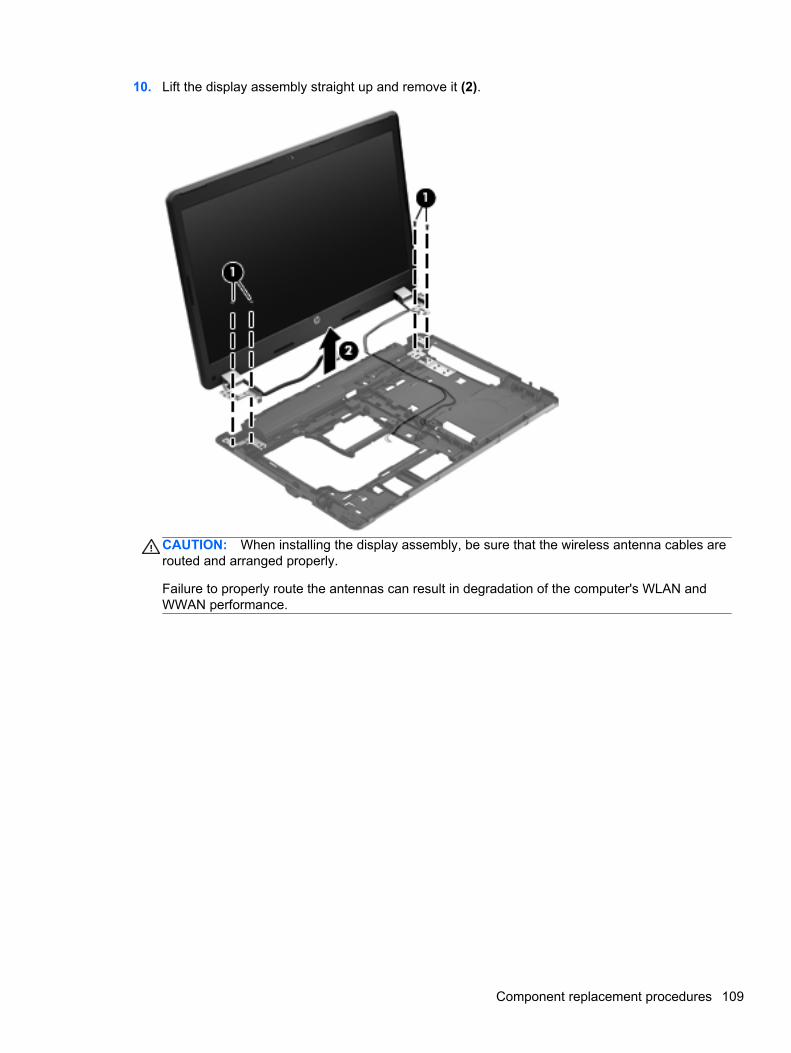
10. Lift the display assembly straight up and remove it (2).
CAUTION: When installing the display assembly, be sure that the wireless antenna cables arerouted and arranged properly.
Failure to properly route the antennas can result in degradation of the computer's WLAN andWWAN performance.
Component replacement procedures 109
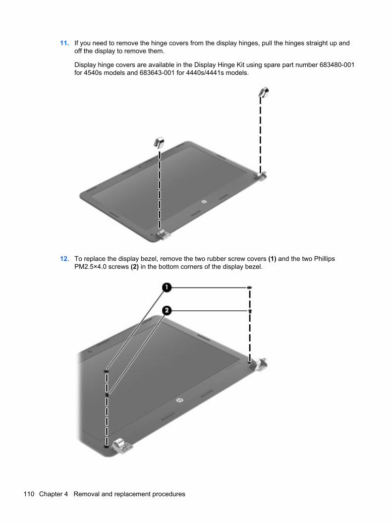
11. If you need to remove the hinge covers from the display hinges, pull the hinges straight up andoff the display to remove them.
Display hinge covers are available in the Display Hinge Kit using spare part number 683480-001for 4540s models and 683643-001 for 4440s/4441s models.
12. To replace the display bezel, remove the two rubber screw covers (1) and the two PhillipsPM2.5×4.0 screws (2) in the bottom corners of the display bezel.
110 Chapter 4 Removal and replacement procedures
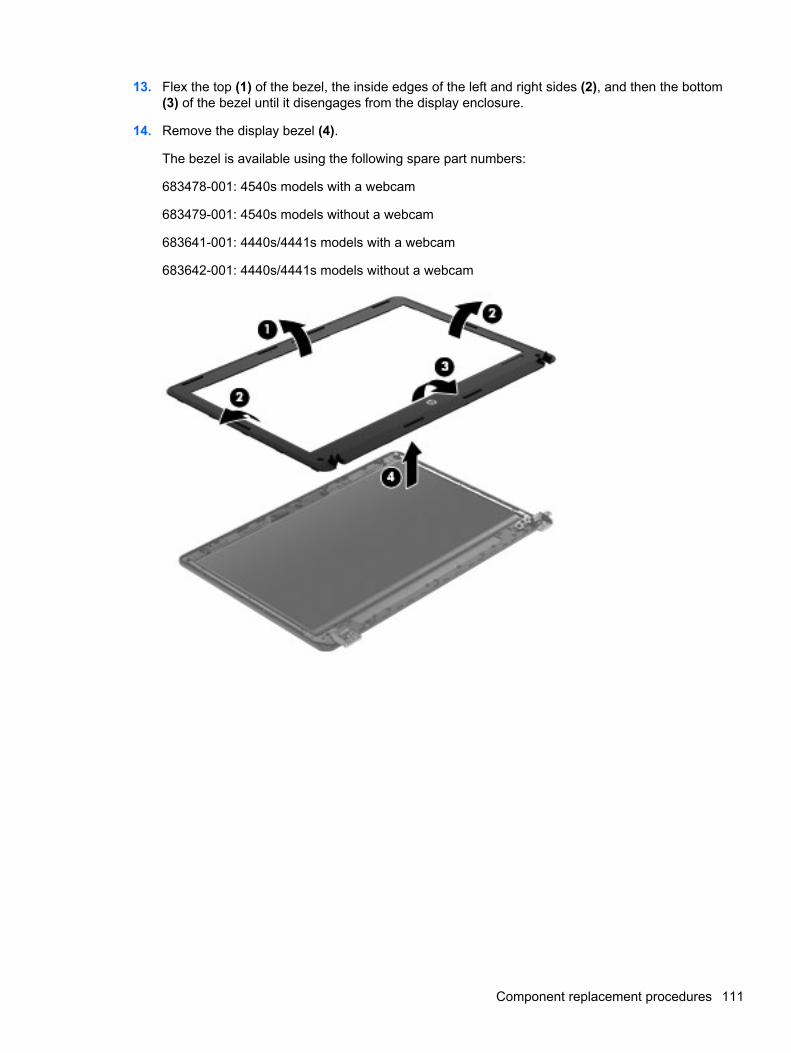
13. Flex the top (1) of the bezel, the inside edges of the left and right sides (2), and then the bottom(3) of the bezel until it disengages from the display enclosure.
14. Remove the display bezel (4).
The bezel is available using the following spare part numbers:
683478-001: 4540s models with a webcam
683479-001: 4540s models without a webcam
683641-001: 4440s/4441s models with a webcam
683642-001: 4440s/4441s models without a webcam
Component replacement procedures 111
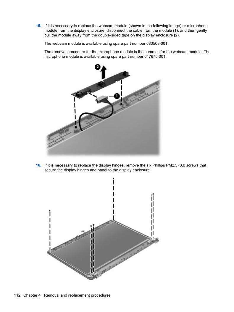
15. If it is necessary to replace the webcam module (shown in the following image) or microphonemodule from the display enclosure, disconnect the cable from the module (1), and then gentlypull the module away from the double-sided tape on the display enclosure (2).
The webcam module is available using spare part number 683508-001.
The removal procedure for the microphone module is the same as for the webcam module. Themicrophone module is available using spare part number 647675-001.
16. If it is necessary to replace the display hinges, remove the six Phillips PM2.5×3.0 screws thatsecure the display hinges and panel to the display enclosure.
112 Chapter 4 Removal and replacement procedures

17. Remove the display hinges and panel from the display enclosure.
18. Disconnect the display panel cable by rotating the display enclosure (1), lifting the tape (2) thatcovers the connector, and disconnecting the cable from the panel (3).
19. Remove the three Phillips PM2.0×3.0 screws (1) that secure each display hinge to the displaypanel.
Component replacement procedures 113
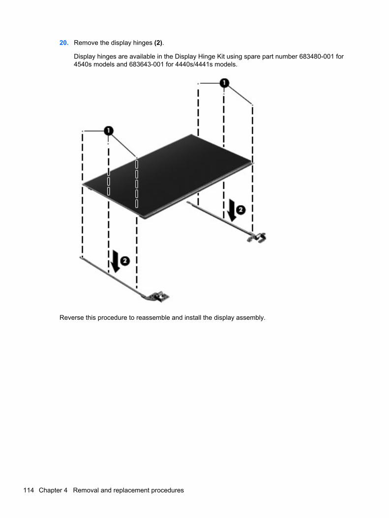
20. Remove the display hinges (2).
Display hinges are available in the Display Hinge Kit using spare part number 683480-001 for4540s models and 683643-001 for 4440s/4441s models.
Reverse this procedure to reassemble and install the display assembly.
114 Chapter 4 Removal and replacement procedures
5 Computer Setup (BIOS) and AdvancedSystem Diagnostics
Windows 7 – Computer Setup (BIOS) and AdvancedSystem Diagnostics
Using Computer Setup
Computer Setup, or Basic Input/Output System (BIOS), controls communication between all the inputand output devices on the system (such as disk drives, display, keyboard, mouse, and printer).Computer Setup includes settings for the types of devices installed, the startup sequence of thecomputer, and the amount of system and extended memory.
NOTE: Use extreme care when making changes in Computer Setup. Errors can prevent thecomputer from operating properly.
Starting Computer Setup
NOTE: An external keyboard or mouse connected to a USB port can be used with Computer Setuponly if USB legacy support is enabled.
To start Computer Setup, follow these steps:
1. Turn on or restart the computer, and then press esc while the “Press the ESC key for StartupMenu” message is displayed at the bottom of the screen.
2. Press f10 to enter Computer Setup.
Navigating and selecting in Computer Setup
To navigate and select in Computer Setup, follow these steps:
1. Turn on or restart the computer, and then press esc while the “Press the ESC key for StartupMenu” message is displayed at the bottom of the screen.
● To select a menu or a menu item, use the tab key and the keyboard arrow keys and thenpress enter, or use a pointing device to click the item.
● To scroll up and down, click the up arrow or the down arrow in the upper-right corner of thescreen, or use the up arrow key or the down arrow key.
● To close open dialog boxes and return to the main Computer Setup screen, press esc, andthen follow the on-screen instructions.
Windows 7 – Computer Setup (BIOS) and Advanced System Diagnostics 115

NOTE: You can use either a pointing device (TouchPad, pointing stick, or USB mouse) or thekeyboard to navigate and make selections in Computer Setup.
2. Press f10 to enter Computer Setup.
To exit Computer Setup menus, choose one of the following methods:
● To exit Computer Setup menus without saving your changes:
Click the Exit icon in the lower-left corner of the screen, and then follow the on-screeninstructions.
– or –
Use the tab key and the arrow keys to select File > Ignore Changes and Exit, and then pressenter.
● To save your changes and exit Computer Setup menus:
Click the Save icon in the lower-left corner of the screen, and then follow the on-screeninstructions.
– or –
Use the tab key and the arrow keys to select File > Save Changes and Exit, and then pressenter.
Your changes go into effect when the computer restarts.
Restoring factory settings in Computer Setup
NOTE: Restoring defaults will not change the hard drive mode.
To return all settings in Computer Setup to the values that were set at the factory, follow these steps:
1. Turn on or restart the computer, and then press esc while the “Press the ESC key for StartupMenu” message is displayed at the bottom of the screen.
2. Press f10 to enter Computer Setup.
3. Use a pointing device or the arrow keys to select File > Restore Defaults.
4. Follow the on-screen instructions.
5. To save your changes and exit, click the Save icon in the lower-left corner of the screen, andthen follow the on-screen instructions.
– or –
Use the arrow keys to select File > Save Changes and Exit, and then press enter.
Your changes go into effect when the computer restarts.
NOTE: Your password settings and security settings are not changed when you restore the factorysettings.
116 Chapter 5 Computer Setup (BIOS) and Advanced System Diagnostics

Updating the BIOS
The next sections describe different ways of updating the BIOS.
Downloading SoftPaqs to update the BIOS
Most BIOS updates on the HP website are packaged in compressed files called SoftPaqs.
To install BIOS updates from the HP website, follow the steps below:
1. Download the SoftPaq from the HP website.
2. Click Run, and then follow the on-screen instructions to update the BIOS.
NOTE: Some download packages contain a file named Readme.txt, which contains informationregarding installing and troubleshooting the file.
BIOS management using system diagnostics
1. Download the SoftPaq from the HP website.
NOTE: Verify that the UEFI system diagnostics is installed on your computer (or USB flashdrive).
2. Click Run, and then click Cancel at the Update/USB bootable dialog box.
3. Navigate to the folder located in c:\swsetup that corresponds to your SoftPaq number.
4. Locate the .bin file in the ROMpaq folder (for example, 68CDD.bin) and then copy it to theHewlett-Packard\BIOS\New\ folder in either the HP_Tools partition of the hard drive, or the USBflash drive.
5. Locate the .sig file in the ROM.cab file and rename it with the same prefix as the .bin file (forexample, 68CDD.sig). Copy the renamed file to the Hewlett-Packard\BIOS\New\ folder in eitherthe HP_Tools partition of the hard drive, or the USB flash drive.
6. Restart the computer, and then press esc while the “Press the ESC key for Startup Menu”message is displayed at the bottom of the screen.
7. Press f2 to enter Computer Setup.
8. Click BIOS Management from the menu and then select Update BIOS.
Using f10 setup to update the BIOS
1. Download the SoftPaq from the HP website.
NOTE: Verify that the UEFI system diagnostics is installed on your computer (or USB flashdrive).
2. Click Run, and then click Cancel at the Update/USB bootable dialog box.
3. Navigate to the folder located in c:\swsetup that corresponds to your SoftPaq number.
4. Locate the .bin file in the ROMpaq folder (for example, 68CDD.bin) and then copy it to theHewlett-Packard\BIOS\New\ folder in either the HP_Tools partition of the hard drive, or the USBflash drive.
Windows 7 – Computer Setup (BIOS) and Advanced System Diagnostics 117

5. Locate the .sig file in the ROM.cab file and rename it with the same prefix as the .bin file (forexample, 68CDD.sig). Copy the renamed file to the Hewlett-Packard\BIOS\New\ folder in eitherthe HP_Tools partition of the hard drive, or the USB flash drive.
6. Restart the computer, and then press esc while the “Press the ESC key for Startup Menu”message is displayed at the bottom of the screen.
7. Press f10 to enter Computer Setup.
8. Click Update System BIOS, and then click Accept to update the BIOS.
Determining the BIOS version
To determine whether available BIOS updates contain later BIOS versions than those currentlyinstalled on the computer, you need to know the version of the system BIOS currently installed.
BIOS version information (also known as ROM date and System BIOS) can be displayed by pressingfn+esc (if you are already in Windows) or by using Computer Setup.
1. Start Computer Setup.
2. Use a pointing device or the arrow keys to select File > System Information.
3. To exit Computer Setup without saving your changes, click the Exit icon in the lower-left cornerof the screen, and then follow the on-screen instructions.
– or –
Use the tab key and the arrow keys to select File > Ignore Changes and Exit, and then pressenter.
118 Chapter 5 Computer Setup (BIOS) and Advanced System Diagnostics
Downloading a BIOS update
CAUTION: To reduce the risk of damage to the computer or an unsuccessful installation, downloadand install a BIOS update only when the computer is connected to reliable external power using theAC adapter. Do not download or install a BIOS update while the computer is running on batterypower, docked in an optional docking device, or connected to an optional power source. During thedownload and installation, follow these instructions:
Do not disconnect power from the computer by unplugging the power cord from the AC outlet.
Do not shut down the computer or initiate Sleep or Hibernation.
Do not insert, remove, connect, or disconnect any device, cable, or cord.
1. Select Start > Help and Support > Maintain.
2. Follow the on-screen instructions to identify your computer and access the BIOS update youwant to download.
3. At the download area, follow these steps:
a. Identify the BIOS update that is later than the BIOS version currently installed on yourcomputer. Make a note of the date, name, or other identifier. You may need this informationto locate the update later, after it has been downloaded to your hard drive.
b. Follow the on-screen instructions to download your selection to the hard drive.
Make a note of the path to the location on your hard drive where the BIOS update isdownloaded. You will need to access this path when you are ready to install the update.
NOTE: If you connect your computer to a network, consult the network administrator beforeinstalling any software updates, especially system BIOS updates.
BIOS installation procedures vary. Follow any instructions that are displayed on the screen after thedownload is complete. If no instructions are displayed, follow these steps:
1. Open Windows Explorer by selecting Start > Computer.
2. Double-click your hard drive designation. The hard drive designation is typically Local Disk (C:).
3. Using the hard drive path you recorded earlier, open the folder on your hard drive that containsthe update.
4. Double-click the file that has an .exe extension (for example, filename.exe).
The BIOS installation begins.
5. Complete the installation by following the on-screen instructions.
NOTE: After a message on the screen reports a successful installation, you can delete thedownloaded file from your hard drive.
BIOS Setup Menu
The tables in this section provide an overview of the BIOS Setup menu options.
Windows 7 – Computer Setup (BIOS) and Advanced System Diagnostics 119
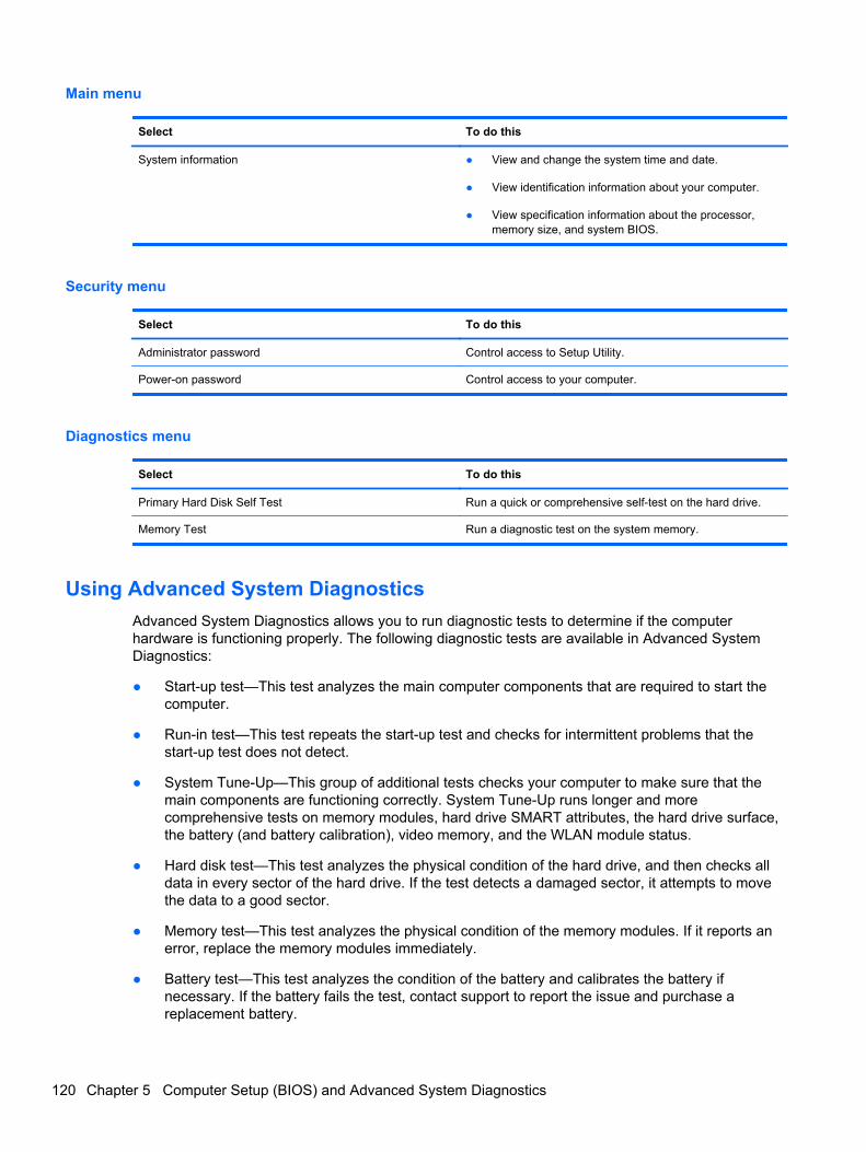
Main menu
Select To do this
System information ● View and change the system time and date.
● View identification information about your computer.
● View specification information about the processor,memory size, and system BIOS.
Security menu
Select To do this
Administrator password Control access to Setup Utility.
Power-on password Control access to your computer.
Diagnostics menu
Select To do this
Primary Hard Disk Self Test Run a quick or comprehensive self-test on the hard drive.
Memory Test Run a diagnostic test on the system memory.
Using Advanced System Diagnostics
Advanced System Diagnostics allows you to run diagnostic tests to determine if the computerhardware is functioning properly. The following diagnostic tests are available in Advanced SystemDiagnostics:
● Start-up test—This test analyzes the main computer components that are required to start thecomputer.
● Run-in test—This test repeats the start-up test and checks for intermittent problems that thestart-up test does not detect.
● System Tune-Up—This group of additional tests checks your computer to make sure that themain components are functioning correctly. System Tune-Up runs longer and morecomprehensive tests on memory modules, hard drive SMART attributes, the hard drive surface,the battery (and battery calibration), video memory, and the WLAN module status.
● Hard disk test—This test analyzes the physical condition of the hard drive, and then checks alldata in every sector of the hard drive. If the test detects a damaged sector, it attempts to movethe data to a good sector.
● Memory test—This test analyzes the physical condition of the memory modules. If it reports anerror, replace the memory modules immediately.
● Battery test—This test analyzes the condition of the battery and calibrates the battery ifnecessary. If the battery fails the test, contact support to report the issue and purchase areplacement battery.
120 Chapter 5 Computer Setup (BIOS) and Advanced System Diagnostics
You can view system information and error logs in the Advanced System Diagnostics window.
To start Advanced System Diagnostics:
1. Turn on or restart the computer. While the “Press the ESC key for Startup Menu” message isdisplayed in the lower-left corner of the screen, press esc. When the Startup Menu is displayed,press f2.
2. Click the diagnostic test you want to run, and then follow the on-screen instructions.
NOTE: If you need to stop a diagnostics test while it is running, press esc.
Windows 8 – Computer Setup (BIOS) and AdvancedSystem Diagnostics
Using Computer Setup
Computer Setup, or Basic Input/Output System (BIOS), controls communication between all the inputand output devices on the system (such as disk drives, display, keyboard, mouse, and printer).Computer Setup includes settings for the types of devices installed, the startup sequence of thecomputer, and the amount of system and extended memory.
NOTE: Use extreme care when making changes in Computer Setup. Errors can prevent thecomputer from operating properly.
Starting Computer Setup
NOTE: An external keyboard or mouse connected to a USB port can be used with Computer Setuponly if USB legacy support is enabled.
To start Computer Setup, follow these steps:
1. Turn on or restart the computer, and then press esc while the “Press the ESC key for StartupMenu” message is displayed at the bottom of the screen.
2. Press f10 to enter Computer Setup.
Navigating and selecting in Computer Setup
To navigate and select in Computer Setup, follow these steps:
1. Turn on or restart the computer, and then press esc while the “Press the ESC key for StartupMenu” message is displayed at the bottom of the screen.
● To select a menu or a menu item, use the tab key and the keyboard arrow keys and thenpress enter, or use a pointing device to click the item.
● To scroll up and down, click the up arrow or the down arrow in the upper-right corner of thescreen, or use the up arrow key or the down arrow key.
● To close open dialog boxes and return to the main Computer Setup screen, press esc, andthen follow the on-screen instructions.
Windows 8 – Computer Setup (BIOS) and Advanced System Diagnostics 121
NOTE: You can use either a pointing device (TouchPad, pointing stick, or USB mouse) or thekeyboard to navigate and make selections in Computer Setup.
2. Press f10 to enter Computer Setup.
To exit Computer Setup menus, choose one of the following methods:
● To exit Computer Setup menus without saving your changes:
Click the Exit icon in the lower-left corner of the screen, and then follow the on-screeninstructions.
– or –
Use the tab key and the arrow keys to select File > Ignore Changes and Exit, and then pressenter.
● To save your changes and exit Computer Setup menus:
Click the Save icon in the lower-left corner of the screen, and then follow the on-screeninstructions.
– or –
Use the tab key and the arrow keys to select File > Save Changes and Exit, and then pressenter.
Your changes go into effect when the computer restarts.
Restoring factory settings in Computer Setup
NOTE: Restoring defaults will not change the hard drive mode.
To return all settings in Computer Setup to the values that were set at the factory, follow these steps:
1. Turn on or restart the computer, and then press esc while the “Press the ESC key for StartupMenu” message is displayed at the bottom of the screen.
2. Press f10 to enter Computer Setup.
3. Use a pointing device or the arrow keys to select File > Restore Defaults.
4. Follow the on-screen instructions.
5. To save your changes and exit, click the Save icon in the lower-left corner of the screen, andthen follow the on-screen instructions.
– or –
Use the arrow keys to select File > Save Changes and Exit, and then press enter.
Your changes go into effect when the computer restarts.
NOTE: Your password settings and security settings are not changed when you restore the factorysettings.
122 Chapter 5 Computer Setup (BIOS) and Advanced System Diagnostics
Updating the BIOS
Updated versions of the BIOS may be available on the HP website.
Most BIOS updates on the HP website are packaged in compressed files called SoftPaqs.
Some download packages contain a file named Readme.txt, which contains information regardinginstalling and troubleshooting the file.
Determining the BIOS version
To determine whether available BIOS updates contain later BIOS versions than those currentlyinstalled on the computer, you need to know the version of the system BIOS currently installed.
BIOS version information (also known as ROM date and System BIOS) can be displayed by pressingfn+esc (if you are already in Windows) or by using Computer Setup.
1. Start Computer Setup.
2. Use a pointing device or the arrow keys to select File > System Information.
3. To exit Computer Setup without saving your changes, click the Exit icon in the lower-left cornerof the screen, and then follow the on-screen instructions.
– or –
Use the tab key and the arrow keys to select File > Ignore Changes and Exit, and then pressenter.
Downloading a BIOS update
CAUTION: To reduce the risk of damage to the computer or an unsuccessful installation, downloadand install a BIOS update only when the computer is connected to reliable external power using theAC adapter. Do not download or install a BIOS update while the computer is running on batterypower, docked in an optional docking device, or connected to an optional power source. During thedownload and installation, follow these instructions:
Do not disconnect power on the computer by unplugging the power cord from the AC outlet.
Do not shut down the computer or initiate sleep.
Do not insert, remove, connect, or disconnect any device, cable, or cord.
1. From the Start screen, type help and then select Help and Support.
2. In the Help and Support search box, type maintain, and then follow the on-screeninstructions to identify your computer and access the BIOS update you want to download.
3. At the download area, follow these steps:
a. Identify the BIOS update that is later than the BIOS version currently installed on yourcomputer. Make a note of the date, name, or other identifier. You may need this informationto locate the update later, after it has been downloaded to your hard drive.
b. Follow the on-screen instructions to download your selection to the hard drive.
Make a note of the path to the location on your hard drive where the BIOS update isdownloaded. You will need to access this path when you are ready to install the update.
Windows 8 – Computer Setup (BIOS) and Advanced System Diagnostics 123
NOTE: If you connect your computer to a network, consult the network administrator beforeinstalling any software updates, especially system BIOS updates.
BIOS installation procedures vary. Follow any instructions that are displayed on the screen after thedownload is complete. If no instructions are displayed, follow these steps:
1. From the Start screen, type windows, and then click Windows Explorer.
2. Double-click your hard drive designation. The hard drive designation is typically Local Disk (C:).
3. Using the hard drive path you recorded earlier, open the folder on your hard drive that containsthe update.
4. Double-click the file that has an .exe extension (for example, filename.exe).
The BIOS installation begins.
5. Complete the installation by following the on-screen instructions.
NOTE: After a message on the screen reports a successful installation, you can delete thedownloaded file from your hard drive.
Using Advanced System Diagnostics
Advanced System Diagnostics allows you to run diagnostic tests to determine if the computerhardware is functioning properly. The following diagnostic tests are available in Advanced SystemDiagnostics:
● System Tune-Up—This group of additional tests checks your computer to make sure that themain components are functioning correctly. System Tune-Up runs longer and morecomprehensive tests on memory modules, hard drive SMART attributes, the hard drive surface,the battery (and battery calibration), video memory, and the WLAN module status.
● Start-up test—This test analyzes the main computer components that are required to start thecomputer.
● Run-in test—This test repeats the start-up test and checks for intermittent problems that thestart-up test does not detect.
● Hard disk test—This test analyzes the physical condition of the hard drive, and then checks alldata in every sector of the hard drive. If the test detects a damaged sector, it attempts to movethe data to a good sector.
● Memory test—This test analyzes the physical condition of the memory modules. If it reports anerror, replace the memory modules immediately.
● Battery test—This test analyzes the condition of the battery and calibrates the battery ifnecessary. If the battery fails the test, contact HP support to report the issue and purchase areplacement battery.
● BIOS Management—You can update or rollback the version of the BIOS on the system. Do notshut down or remove external power during the process. You will be given a confirmation screenbefore your BIOS is modified. Select BIOS update, BIOS Rollback, or Back to main menu.
You can view system information and error logs or select languages in the Advanced SystemDiagnostics window.
124 Chapter 5 Computer Setup (BIOS) and Advanced System Diagnostics

To start Advanced System Diagnostics:
1. Turn on or restart the computer. While the “Press the ESC key for Startup Menu” message isdisplayed in the lower-left corner of the screen, press esc. When the Startup Menu is displayed,press f2.
2. Click the diagnostic test you want to run, and then follow the on-screen instructions.
NOTE: If you need to stop a diagnostics test while it is running, press esc.
SUSE Linux – Computer Setup (BIOS) and AdvancedSystem Diagnostics
Computer Setup, or Basic Input/Output System (BIOS), controls communication between all the inputand output devices on the system (such as disk drives, display, keyboard, mouse, and printer).Computer Setup includes settings for the types of peripherals installed, the startup sequence of thecomputer, and the amount of system and extended memory.
NOTE: Use extreme care when making changes in Computer Setup. Errors can prevent thecomputer from operating properly.
Starting Computer Setup
NOTE: An external keyboard or mouse connected to a USB port can be used with Computer Setuponly if USB legacy support is enabled.
To start Computer Setup, follow these steps:
1. Turn on or restart the computer, and then press esc while the “Press the ESC key for StartupMenu” message is displayed at the bottom of the screen.
2. Press f10 to enter Computer Setup.
Using Computer Setup
Navigating and selecting in Computer Setup
To navigate and select in Computer Setup, follow these steps:
1. Turn on or restart the computer, and then press esc while the “Press the ESC key for StartupMenu” message is displayed at the bottom of the screen.
● To select a menu or a menu item, use the tab key and the keyboard arrow keys and thenpress enter, or use a pointing device to click the item.
● To scroll up and down, click the up arrow or the down arrow in the upper-right corner of thescreen, or use the up arrow key or the down arrow key.
● To close open dialog boxes and return to the main Computer Setup screen, press esc, andthen follow the on-screen instructions.
NOTE: You can use either a pointing device (TouchPad, pointing stick, or USB mouse) or thekeyboard to navigate and make selections in Computer Setup.
2. Press f10 to enter Computer Setup.
SUSE Linux – Computer Setup (BIOS) and Advanced System Diagnostics 125
To exit Computer Setup menus, choose one of the following methods:
● To exit Computer Setup menus without saving your changes, click the Exit icon in the lower-leftcorner of the screen, and then follow the on-screen instructions.
– or –
Use the tab key and the arrow keys to select File > Ignore Changes and Exit, and then pressenter.
– or –
● To save your changes and exit Computer Setup menus, click the Save icon in the lower-leftcorner of the screen, and then follow the on-screen instructions.
– or –
Use the tab key and the arrow keys to select File > Save Changes and Exit, and then pressenter.
Your changes go into effect when the computer restarts.
Restoring factory settings in Computer Setup
NOTE: Restoring defaults will not change the hard drive mode.
To return all settings in Computer Setup to the values that were set at the factory, follow these steps:
1. Turn on or restart the computer, and then press esc while the “Press the ESC key for StartupMenu” message is displayed at the bottom of the screen.
2. Press f10 to enter Computer Setup.
3. Use a pointing device or the arrow keys to select File > Restore Defaults.
4. Follow the on-screen instructions.
5. To save your changes and exit, click the Save icon in the lower-left corner of the screen, andthen follow the on-screen instructions.
– or –
Use the arrow keys to select File > Save Changes and Exit, and then press enter.
Your changes go into effect when the computer restarts.
NOTE: Your password settings and security settings are not changed when you restore the factorysettings.
Updating the BIOS
Updated versions of the BIOS may be available on the HP Web site.
Most BIOS updates on the HP Web site are packaged in compressed files called SoftPaqs.
Some download packages contain a file named Readme.txt, which contains information regardinginstalling and troubleshooting the file.
126 Chapter 5 Computer Setup (BIOS) and Advanced System Diagnostics
Determining the BIOS version
To determine whether available BIOS updates contain later BIOS versions than those currentlyinstalled on the computer, you need to know the version of the system BIOS currently installed.
BIOS version information (also known as ROM date and System BIOS) can be displayed by startingComputer Setup.
1. Start Computer Setup.
2. Use a pointing device or the arrow keys to select File > System Information.
3. To exit Computer Setup without saving your changes, click the Exit icon in the lower-left cornerof the screen, and then follow the on-screen instructions.
– or –
Use the tab key and the arrow keys to select File > Ignore Changes and Exit, and then pressenter.
NOTE: You can also determine the BIOS version by turning on or restarting the computer, pressingthe esc key while the “Press the ESC key for Startup Menu” message is displayed at the bottom ofthe screen, and then pressing the f1 key. Follow the on-screen instructions to exit this screen.
Downloading a BIOS update
CAUTION: To reduce the risk of damage to the computer or an unsuccessful installation, downloadand install a BIOS update only when the computer is connected to reliable external power using theAC adapter. Do not download or install a BIOS update while the computer is running on batterypower, docked in an optional docking device, or connected to an optional power source. During thedownload and installation, follow these instructions:
Do not disconnect power from the computer by unplugging the power cord from the AC outlet.
Do not shut down the computer or initiate Suspend or Hibernation.
Do not insert, remove, connect, or disconnect any device, cable, or cord.
1. Open your Web browser, go to http://www.hp.com/support, and select your country or region.Access the page on the HP Web site that provides software for your computer. Follow the on-screen instructions to identify your computer and access the BIOS update you want todownload.
2. Click the option for software and driver downloads, type your computer model number in theproduct box, and then press enter. Follow the on-screen instructions to identify your computerand access the BIOS update you want to download.
3. Click your specific product from the models listed.
4. Click the appropriate operating system.
5. Go to the BIOS section and download the BIOS software package.
6. Follow the installation instructions as provided with the downloaded BIOS software package.
NOTE: After a message on the screen reports a successful installation, you can delete thedownloaded file from your hard drive.
SUSE Linux – Computer Setup (BIOS) and Advanced System Diagnostics 127
Using Advanced System Diagnostics
Advanced System Diagnostics allows you to run diagnostic tests to determine if the computerhardware is functioning properly. The following diagnostic tests are available in Advanced SystemDiagnostics:
● Start-up test—This test analyzes the main computer components that are required to start thecomputer.
● Run-in test—This test repeats the start-up test and checks for intermittent problems that thestart-up test does not detect.
● Hard disk test—This test analyzes the physical condition of the hard drive, and then checks alldata in every sector of the hard drive. If the test detects a damaged sector, it attempts to movethe data to a good sector.
● Memory test—This test analyzes the physical condition of the memory modules. If it reports anerror, replace the memory modules immediately.
● Battery test—This test analyzes the condition of the battery and calibrates the battery ifnecessary. If the battery fails the test, contact HP Customer Support to report the issue andpurchase a replacement battery.
● System Tune-Up—This group of additional tests checks your computer to make sure that themain components are functioning correctly. System Tune-Up runs longer and morecomprehensive tests on memory modules, hard drive SMART attributes, the hard drive surface,the battery (and battery calibration), video memory, and the WLAN module status.
You can view system information and error logs in the Advanced System Diagnostics window.
To start Advanced System Diagnostics:
1. Turn on or restart the computer. While the “Press the ESC key for Startup Menu” message isdisplayed in the lower-left corner of the screen, press esc. When the Startup Menu is displayed,press f2.
2. Click the diagnostic test you want to run, and then follow the on-screen instructions.
NOTE: If you need to stop a diagnostics test while it is running, press esc.
128 Chapter 5 Computer Setup (BIOS) and Advanced System Diagnostics
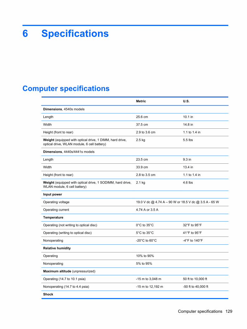
6 Specifications
Computer specifications
Metric U.S.
Dimensions, 4540s models
Length 25.6 cm 10.1 in
Width 37.5 cm 14.8 in
Height (front to rear) 2.9 to 3.6 cm 1.1 to 1.4 in
Weight (equipped with optical drive, 1 DIMM, hard drive,optical drive, WLAN module, 6 cell battery)
2.5 kg 5.5 lbs
Dimensions, 4440s/4441s models
Length 23.5 cm 9.3 in
Width 33.9 cm 13.4 in
Height (front to rear) 2.8 to 3.5 cm 1.1 to 1.4 in
Weight (equipped with optical drive, 1 SODIMM, hard drive,WLAN module, 6 cell battery)
2.1 kg 4.6 lbs
Input power
Operating voltage 19.0 V dc @ 4.74 A – 90 W or 18.5 V dc @ 3.5 A - 65 W
Operating current 4.74 A or 3.5 A
Temperature
Operating (not writing to optical disc) 0°C to 35°C 32°F to 95°F
Operating (writing to optical disc) 5°C to 35°C 41°F to 95°F
Nonoperating -20°C to 60°C -4°F to 140°F
Relative humidity
Operating 10% to 90%
Nonoperating 5% to 95%
Maximum altitude (unpressurized)
Operating (14.7 to 10.1 psia) -15 m to 3,048 m 50 ft to 10,000 ft
Nonoperating (14.7 to 4.4 psia) -15 m to 12,192 m -50 ft to 40,000 ft
Shock
Computer specifications 129
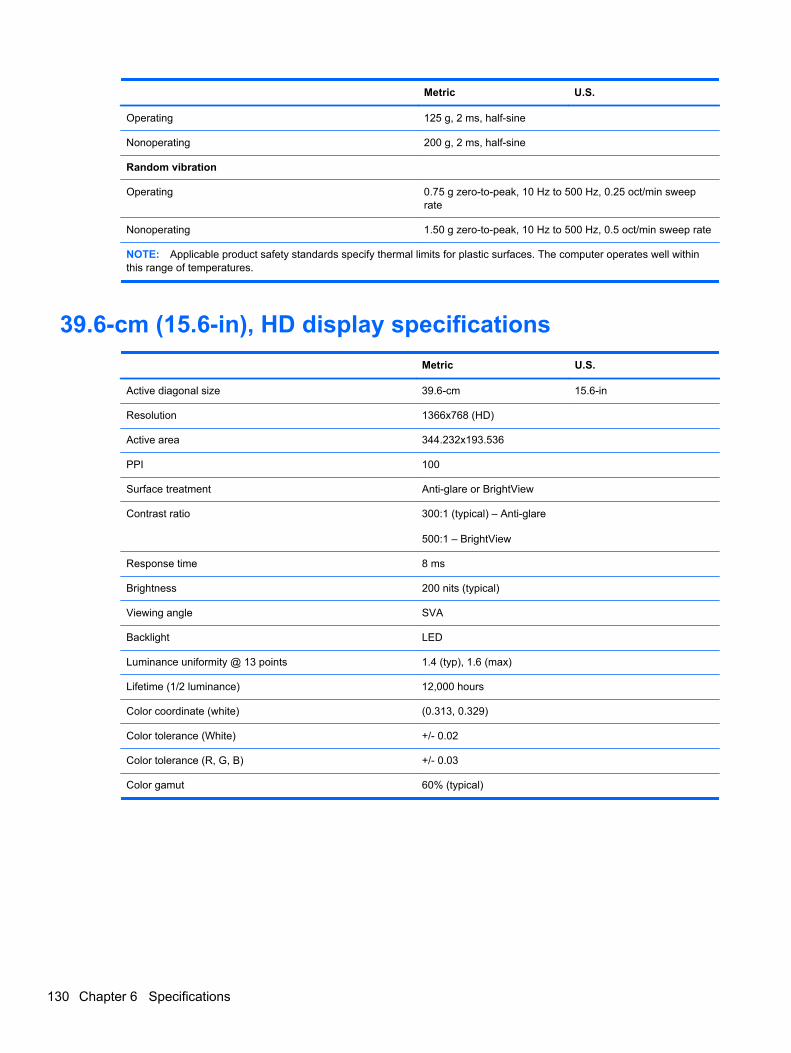
Metric U.S.
Operating 125 g, 2 ms, half-sine
Nonoperating 200 g, 2 ms, half-sine
Random vibration
Operating 0.75 g zero-to-peak, 10 Hz to 500 Hz, 0.25 oct/min sweeprate
Nonoperating 1.50 g zero-to-peak, 10 Hz to 500 Hz, 0.5 oct/min sweep rate
NOTE: Applicable product safety standards specify thermal limits for plastic surfaces. The computer operates well withinthis range of temperatures.
39.6-cm (15.6-in), HD display specifications
Metric U.S.
Active diagonal size 39.6-cm 15.6-in
Resolution 1366x768 (HD)
Active area 344.232x193.536
PPI 100
Surface treatment Anti-glare or BrightView
Contrast ratio 300:1 (typical) – Anti-glare
500:1 – BrightView
Response time 8 ms
Brightness 200 nits (typical)
Viewing angle SVA
Backlight LED
Luminance uniformity @ 13 points 1.4 (typ), 1.6 (max)
Lifetime (1/2 luminance) 12,000 hours
Color coordinate (white) (0.313, 0.329)
Color tolerance (White) +/- 0.02
Color tolerance (R, G, B) +/- 0.03
Color gamut 60% (typical)
130 Chapter 6 Specifications
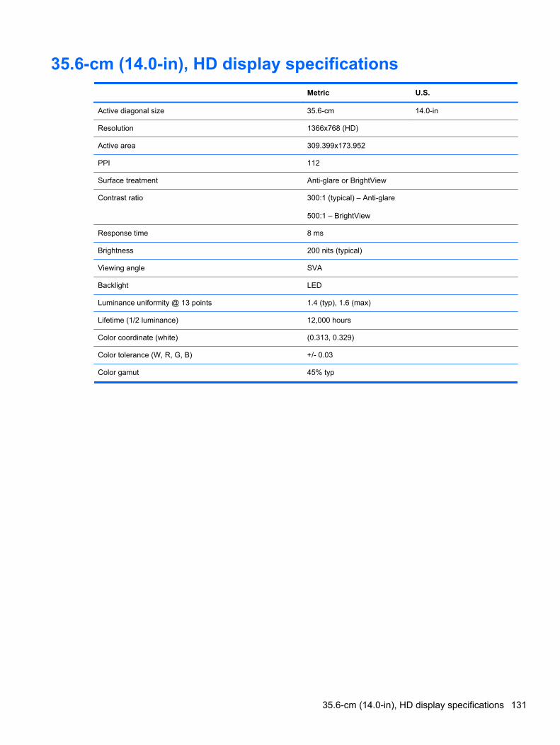
35.6-cm (14.0-in), HD display specifications
Metric U.S.
Active diagonal size 35.6-cm 14.0-in
Resolution 1366x768 (HD)
Active area 309.399x173.952
PPI 112
Surface treatment Anti-glare or BrightView
Contrast ratio 300:1 (typical) – Anti-glare
500:1 – BrightView
Response time 8 ms
Brightness 200 nits (typical)
Viewing angle SVA
Backlight LED
Luminance uniformity @ 13 points 1.4 (typ), 1.6 (max)
Lifetime (1/2 luminance) 12,000 hours
Color coordinate (white) (0.313, 0.329)
Color tolerance (W, R, G, B) +/- 0.03
Color gamut 45% typ
35.6-cm (14.0-in), HD display specifications 131
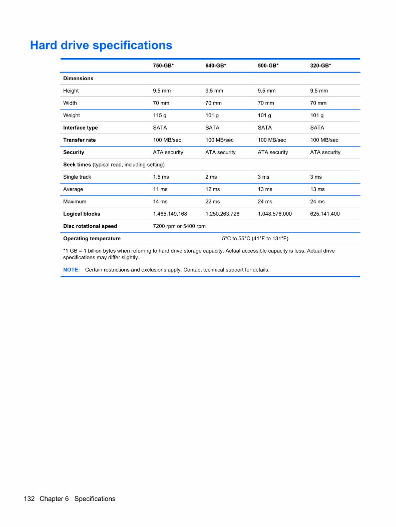
Hard drive specifications
750-GB* 640-GB* 500-GB* 320-GB*
Dimensions
Height 9.5 mm 9.5 mm 9.5 mm 9.5 mm
Width 70 mm 70 mm 70 mm 70 mm
Weight 115 g 101 g 101 g 101 g
Interface type SATA SATA SATA SATA
Transfer rate 100 MB/sec 100 MB/sec 100 MB/sec 100 MB/sec
Security ATA security ATA security ATA security ATA security
Seek times (typical read, including setting)
Single track 1.5 ms 2 ms 3 ms 3 ms
Average 11 ms 12 ms 13 ms 13 ms
Maximum 14 ms 22 ms 24 ms 24 ms
Logical blocks 1,465,149,168 1,250,263,728 1,048,576,000 625,141,400
Disc rotational speed 7200 rpm or 5400 rpm
Operating temperature 5°C to 55°C (41°F to 131°F)
*1 GB = 1 billion bytes when referring to hard drive storage capacity. Actual accessible capacity is less. Actual drivespecifications may differ slightly.
NOTE: Certain restrictions and exclusions apply. Contact technical support for details.
132 Chapter 6 Specifications
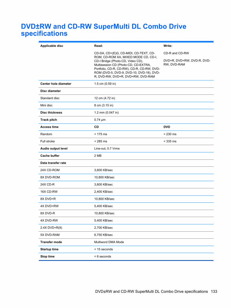
DVD±RW and CD-RW SuperMulti DL Combo Drivespecifications
Applicable disc Read:
CD-DA, CD+(E)G, CD-MIDI, CD-TEXT, CD-ROM, CD-ROM XA, MIXED MODE CD, CD-I,CD-I Bridge (Photo-CD, Video CD),Multisession CD (Photo-CD, CD-EXTRA,Portfolio, CD-R, CD-RW), CD-R, CD-RW, DVD-ROM (DVD-5, DVD-9, DVD-10, DVD-18), DVD-R, DVD-RW, DVD+R, DVD+RW, DVD-RAM
Write:
CD-R and CD-RW
DVD+R, DVD+RW, DVD-R, DVD-RW, DVD-RAM
Center hole diameter 1.5 cm (0.59 in)
Disc diameter
Standard disc 12 cm (4.72 in)
Mini disc 8 cm (3.15 in)
Disc thickness 1.2 mm (0.047 in)
Track pitch 0.74 µm
Access time CD DVD
Random < 175 ms < 230 ms
Full stroke < 285 ms < 335 ms
Audio output level Line-out, 0.7 Vrms
Cache buffer 2 MB
Data transfer rate
24X CD-ROM 3,600 KB/sec
8X DVD-ROM 10,800 KB/sec
24X CD-R 3,600 KB/sec
16X CD-RW 2,400 KB/sec
8X DVD+R 10,800 KB/sec
4X DVD+RW 5,400 KB/sec
8X DVD-R 10,800 KB/sec
4X DVD-RW 5,400 KB/sec
2.4X DVD+R(9) 2,700 KB/sec
5X DVD-RAM 6,750 KB/sec
Transfer mode Multiword DMA Mode
Startup time < 15 seconds
Stop time < 6 seconds
DVD±RW and CD-RW SuperMulti DL Combo Drive specifications 133
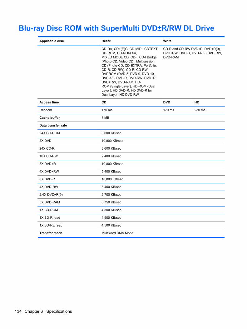
Blu-ray Disc ROM with SuperMulti DVD±R/RW DL Drive
Applicable disc Read: Write:
CD-DA, CD+(E)G, CD-MIDI, CDTEXT,CD-ROM, CD-ROM XA,MIXED MODE CD, CD-I, CD-I Bridge(Photo-CD, Video CD), MultisessionCD (Photo-CD, CD-EXTRA, Portfolio,CD-R, CD-RW), CD-R, CD-RW,DVDROM (DVD-5, DVD-9, DVD-10,DVD-18), DVD-R, DVD-RW, DVD+R,DVD+RW, DVD-RAM, HD-ROM (Single Layer), HD-ROM (DualLayer), HD DVD-R, HD DVD-R forDual Layer, HD DVD-RW
CD-R and CD-RW DVD+R, DVD+R(9),DVD+RW, DVD-R, DVD-R(9),DVD-RW,DVD-RAM
Access time CD DVD HD
Random 170 ms 170 ms 230 ms
Cache buffer 8 MB
Data transfer rate
24X CD-ROM 3,600 KB/sec
8X DVD 10,800 KB/sec
24X CD-R 3,600 KB/sec
16X CD-RW 2,400 KB/sec
8X DVD+R 10,800 KB/sec
4X DVD+RW 5,400 KB/sec
8X DVD-R 10,800 KB/sec
4X DVD-RW 5,400 KB/sec
2.4X DVD+R(9) 2,700 KB/sec
5X DVD-RAM 6,750 KB/sec
1X BD-ROM 4,500 KB/sec
1X BD-R read 4,500 KB/sec
1X BD-RE read 4,500 KB/sec
Transfer mode Multiword DMA Mode
134 Chapter 6 Specifications
Specification information in Device ManagerDevice Manager allows you to view and control the hardware attached to the computer, as well asprovides hardware specification information.
You can also add hardware or modify device configurations using Device Manager.
NOTE: Windows 7 includes the User Account Control feature to improve the security of yourcomputer. You may be prompted for your permission or password for tasks such as installingsoftware, running utilities, or changing Windows settings. Refer to Windows Help and Support formore information.
After you open Device Manager, drill-down to a device and double-click it to access its properties.
To access Device Manager in Windows 8:
1. From the Start screen, type control, and then select Control Panel.
2. Select System and Security, and then in the System area, click Device Manager.
A list display all the devices installed in your computer.
To access Device Manager in Windows 7:
1. Select Start > Computer > System properties.
2. In the left pane, click Device Manager.
To access Device Manager in Windows XP:
1. Select Start > My Computer.
2. In the left pane of the System Tasks window, select View system information.
3. Select Hardware tab > Device Manager.
Specification information in Device Manager 135
7 Backup and recovery
Windows 7 – Backup and recoveryTo protect your information, use Windows Backup and Restore to back up individual files and folders,back up your entire hard drive (select models only), create system repair discs (select models only)with the installed optical drive (select models only) or an optional external optical drive, or createsystem restore points. In case of system failure, you can use the backup files to restore the contentsof your computer.
Windows Backup and Restore provides the following options:
● Creating a system repair disc (select models only) by using the installed optical drive (selectmodels only) or an optional external optical drive
● Backing up your information
● Creating a system image (select models only)
● Scheduling automatic backups (select models only)
● Creating system restore points
● Recovering individual files
● Restoring the computer to a previous state
● Recovering information using recovery tools
NOTE: For detailed instructions, perform a search for these topics in Help and Support.
In case of system instability, HP recommends that you print the recovery procedures and save themfor later use.
NOTE: Windows includes the User Account Control feature to improve the security of yourcomputer. You may be prompted for your permission or password for tasks such as installingsoftware, running utilities, or changing Windows settings. See Help and Support for more information.
136 Chapter 7 Backup and recovery
Creating recovery media with HP Recovery Disc Creator
HP Recovery Disc Creator is a software program that offers an alternative way to create recoverymedia. After you successfully set up the computer, you can create recovery media using HPRecovery Disc Creator. This recovery media allows you to reinstall your original operating system aswell as select drivers and applications if the hard drive becomes corrupted.
HP Recovery Disc Creator can create two kinds of recovery DVDs as follows:
● Windows DVD—Installs the operating system without additional drivers or applications.
● Driver DVD—Installs specific drivers and applications only, in the same way that the HPSoftware Setup utility installs drivers and applications.
Creating recovery media
NOTE: The Windows DVD can be created only once. Thereafter, the option to create that media willnot be available.
1. Select Start > All Programs > Productivity and Tools > HP Recovery Disc Creator.
2. Select Driver Disk or Windows Disk.
3. From the drop-down menu, select the drive for burning the recovery media.
4. Click the Create button to start the burning process.
Backing up your information
Recovery after a system failure is as good as your most recent backup. Immediately after setting upthe computer, you should create system repair discs (select models only) using the installed opticaldrive (select models only) or an optional external optical drive and back up your system. As you addnew software and data files, you should continue to back up your system on a regular basis tomaintain a reasonably current backup. The system repair discs (select models only) are used to startup (boot) the computer and repair the operating system in case of system instability or failure. Yourinitial and subsequent backups allow you to restore your data and settings if a failure occurs.
You can back up your information to an optional external hard drive, a network drive, or discs.
Note the following when backing up:
● Store personal files in the Documents library, and back it up regularly.
● Back up templates that are stored in their associated programs.
● Save customized settings that appear in a window, toolbar, or menu bar by taking a screen shotof your settings. The screen shot can be a time-saver if you have to reset your preferences.
● When backing up to discs, use any of the following types of discs (purchased separately): CD-R,CD-RW, DVD+R, DVD+R DL, DVD-R, DVD-R DL, or DVD±RW. The discs you use will dependon the type of optical drive you are using.
NOTE: DVDs and DVDs with double-layer (DL) support store more information than CDs, sousing them for backup reduces the number of recovery discs required.
● When backing up to discs, number each disc before inserting it into the external drive.
To create a backup using Backup and Restore:
Windows 7 – Backup and recovery 137

NOTE: Be sure that the computer is connected to AC power before you start the backup process.
NOTE: The backup process may take over an hour, depending on file size and the speed ofthe computer.
1. Select Start > All Programs > Maintenance > Backup and Restore.
2. Follow the on-screen instructions to set up your backup, create a system image (select modelsonly), or create a system repair disc (select models only).
Performing a system recovery
In case of system failure or instability, the computer provides the following tools to recover your files:
● Windows recovery tools: You can use Windows Backup and Restore to recover information youhave previously backed up. You can also use Windows Startup Repair to fix problems that mightprevent Windows from starting correctly.
● f11 recovery tools: You can use the f11 recovery tools to recover your original hard drive image.The image includes the Windows operating system and software programs installed at thefactory.
NOTE: If you are unable to boot (start up) your computer and you cannot use the system repairdiscs you previously created (select models only), you must purchase a Windows 7 operating systemDVD to reboot the computer and repair the operating system. For additional information, see theUsing a Windows 7 operating system DVD (purchased separately) section.
Using the Windows recovery tools
To recover information you previously backed up:
1. Select Start > All Programs > Maintenance > Backup and Restore.
2. Follow the on-screen instructions to recover your system settings, your computer (select modelsonly), or your files.
To recover your information using Startup Repair, follow these steps:
CAUTION: Some Startup Repair options completely erase hard drive contents and reformat thehard drive. All files you have created and any software installed on the computer are permanentlyremoved. When reformatting is complete, the recovery process restores the operating system, as wellas the drivers, software, and utilities from the backup used for recovery.
1. If possible, back up all personal files.
2. If possible, check for the presence of the Windows partition.
To check for the Windows partition, select Start > Computer.
3. If the Windows partition is listed, restart the computer, and then press f8 before the Windowsoperating system loads.
4. Select Startup Repair.
5. Follow the on-screen instructions.
NOTE: For additional information on recovering information using the Windows tools, perform asearch for these topics in Help and Support.
138 Chapter 7 Backup and recovery
Using f11 recovery tools
CAUTION: Using f11 recovery tools completely erases hard drive contents and reformats the harddrive. All files you have created and any software installed on the computer are permanentlyremoved. The f11 recovery tool reinstalls the operating system and HP programs and drivers thatwere installed at the factory. Software not installed at the factory must be reinstalled.
To recover the original hard drive image using f11:
1. If possible, back up all personal files.
2. If possible, check for the presence of the HP Recovery partition: click Start, right-clickComputer, click Manage, and then click Disk Management.
NOTE: If the HP Recovery partition has been deleted, the f11 restore option will not function.You must recover your operating system and programs using the Windows 7 operating systemDVD and the Driver Recovery disc (both purchased separately) if the Windows partition and theHP Recovery partition are not listed. For additional information, see the Using a Windows 7operating system DVD (purchased separately) section.
3. If the HP Recovery partition is listed, restart the computer, and then press esc while the “Pressthe ESC key for Startup Menu” message is displayed at the bottom of the screen.
4. Press f11 while the “Press <F11>” for recovery” message is displayed on the screen.
5. Follow the on-screen instructions.
Windows 7 – Backup and recovery 139
Using a Windows 7 operating system DVD (purchased separately)
To order a Windows 7 operating system DVD, go to the HP website. For U.S. support, go tohttp:// www.hp.com/go/contactHP. For worldwide support, go to http://welcome.hp.com/country/us/en/wwcontact_us.html. You can also order the DVD by calling support. For contact information, see theWorldwide Telephone Numbers booklet included with the computer.
CAUTION: Using a Windows 7 operating system DVD completely erases hard drive contents andreformats the hard drive. All files you have created and any software installed on the computer arepermanently removed. When reformatting is complete, the recovery process helps you restore theoperating system, as well as drivers, software, and utilities.
To initiate recovery using a Windows 7 operating system DVD:
NOTE: This process takes several minutes.
1. If possible, back up all personal files.
2. Restart the computer, and then insert the Windows 7 operating system DVD into the opticaldrive before the Windows operating system loads.
3. When prompted, press any keyboard key.
4. Follow the on-screen instructions.
5. Click Next.
6. Select Repair your computer.
7. Follow the on-screen instructions.
After the repair is completed:
1. Eject the Windows 7 operating system DVD, and then insert the Driver Recovery disc.
2. Install the Hardware Enabling Drivers first, and then install Recommended Applications.
Windows 8 – Backup and recoveryTo protect your information, use Windows backup and restore utilities to back up individual files andfolders, back up your entire hard drive, create system repair media (select models only) by using theinstalled optical drive (select models only) or an optional external optical drive, or create systemrestore points. In case of system failure, you can use the backup files to restore the contents of yourcomputer.
From the Start screen, type restore, click Settings, and then select from the list of displayedoptions.
NOTE: For detailed instructions on various backup and restore options, perform a search for thesetopics in Help and Support. From the Start screen, type h, and then select Help and Support.
In case of system instability, HP recommends that you print the recovery procedures and save themfor later use.
140 Chapter 7 Backup and recovery
NOTE: Windows includes the User Account Control feature to improve the security of yourcomputer. You may be prompted for your permission or password for tasks such as installingsoftware, running utilities, or changing Windows settings. Refer to Help and Support for moreinformation. From the Start screen, type h, and then select Help and Support.
Backing up your information
Recovery after a system failure is as good as your most recent backup. You should create systemrepair media and your initial backup immediately after initial system setup. As you add new softwareand data files, you should continue to back up your system on a regular basis to maintain areasonably current backup. The system repair media (select models only) are used to start up (boot)the computer and repair the operating system in case of system instability or failure. Your initial andsubsequent backups allow you to restore your data and settings if a failure occurs.
On Start screen, type backup, click Settings, and then select Save backup copies of your fileswith File History.
You can back up your information to an optional external hard drive or a network drive.
Note the following when backing up:
● Store personal files in the Documents library, and back it up regularly.
● Back up templates that are stored in their associated programs.
● Save customized settings that appear in a window, toolbar, or menu bar by taking a screen shotof your settings. The screen shot can be a time-saver if you have to reset your preferences.
To create a backup using Backup and Restore:
NOTE: Be sure that the computer is connected to AC power before you start the backup process.
NOTE: The backup process may take over an hour, depending on file size and the speed of thecomputer.
1. From the Start screen, type backup, click Settings, and then select from the list of displayedoptions.
2. Follow the on-screen instructions to set up your backup, create a system image (select modelsonly), or create system repair media (select models only).
Performing a system recovery
In case of system failure or instability, the computer provides the following tools to recover your files:
● Windows recovery tools: You can use Windows Backup and Restore to recover information youhave previously backed up. You can also use Windows Startup Repair to fix problems that mightprevent Windows from starting correctly.
● f11 recovery tools: You can use the f11 recovery tools to recover your original hard drive image.The image includes the Windows operating system and software programs installed at thefactory.
NOTE: If you are unable to boot (start up) your computer and you cannot use the system repairmedia you previously created (select models only), you must purchase Windows 8 operating systemmedia to reboot the computer and repair the operating system.
Windows 8 – Backup and recovery 141
Using the Windows recovery tools
To recover information you previously backed up:
▲ From the Start screen, type h, and then select Help and Support.
To recover your information using Automatic Repair, follow these steps:
CAUTION: Some Automatic Repair options will completely erase and reformat the hard drive. Allfiles you have created and any software installed on the computer are permanently removed. Whenreformatting is complete, the recovery process restores the operating system, as well as the drivers,software, and utilities from the backup used for recovery.
1. If possible, back up all personal files.
2. If possible, check for the presence of the HP Recovery partition and the Windows partition.
From the Start screen, type e, and then click File Explorer.
– or –
From the Start screen, type c, and then select Computer.
NOTE: If the Windows partition and the HP Recovery partition are not listed, you must recoveryour operating system and programs using the Windows 8 operating system DVD and the DriverRecovery media (both purchased separately). For additional information, see Using Windows 8operating system media (purchased separately) on page 143.
3. If the Windows partition and the HP Recovery partition are listed, restart the computer. AfterWindows has loaded, press and hold the shift key while clicking Restart.
4. Select Troubleshoot, select Advanced Options, and then select Automatic Repair.
5. Follow the on-screen instructions.
NOTE: For additional information on recovering information using the Windows tools, perform asearch for these topics in Help and Support. From the Start screen, type h, and then select Help andSupport.
Using f11 recovery tools
CAUTION: Using f11 completely erases hard drive contents and reformats the hard drive. All filesthat you have created and any software that you have installed on the computer are permanentlyremoved. The f11 recovery tool reinstalls the operating system and HP programs and drivers thatwere installed at the factory. Software not installed at the factory must be reinstalled.
To recover the original hard drive image using f11:
1. If possible, back up all personal files.
2. If possible, check for the presence of the HP Recovery partition: From the Start screen, type C,and then select Computer.
NOTE: If the HP Recovery partition is not listed, you must recover your operating system andprograms using the Windows 8 operating system media and the Driver Recovery media (bothpurchased separately). For additional information, see Using Windows 8 operating systemmedia (purchased separately) on page 143.
142 Chapter 7 Backup and recovery
3. If the HP Recovery partition is listed, restart the computer, and then press esc while the “Pressthe ESC key for Startup Menu” message is displayed at the bottom of the screen.
4. Press f11 while the “Press <F11> for recovery” message is displayed on the screen.
5. Follow the on-screen instructions.
Using Windows 8 operating system media (purchased separately)
To order a Windows 8 operating system DVD, go to http://www.hp.com/support, select your countryor region, and follow the on-screen instructions. You can also order the DVD by calling support. Forcontact information, see the Worldwide Telephone Numbers booklet included with the computer.
CAUTION: Using a Windows 8 operating system media completely erases hard drive contents andreformats the hard drive. All files that you have created and any software that you have installed onthe computer are permanently removed. When reformatting is complete, the recovery process helpsyou restore the operating system, as well as drivers, software, and utilities.
To initiate recovery using a Windows 8 operating system DVD:
NOTE: This process takes several minutes.
1. If possible, back up all personal files.
2. Restart the computer, and then insert the Windows 8 operating system DVD into the opticaldrive before the Windows operating system loads.
3. When prompted, press any keyboard key.
4. Follow the on-screen instructions.
After the repair is completed:
1. Eject the Windows 8 operating system media and then insert the Driver Recovery media.
2. Install the Hardware Enabling Drivers first, and then install Recommended Applications.
Windows 8 – Backup and recovery 143
Using Windows Refresh for quick and easy recovery
When your computer is not working properly and you need to regain system stability, the WindowsRefresh option allows you to start fresh and keep what is important to you.
IMPORTANT: Refresh removes any traditional applications that were not originally installed on thesystem at the factory.
NOTE: During Refresh, a list of removed traditional applications will be saved so that you have aquick way to see what you might need to reinstall. See Help and Support for instructions onreinstalling traditional applications. From the Start screen, type h, and then select Help and Support.
NOTE: You may be prompted for your permission or password when using Refresh. See WindowsHelp and Support for more information. From the Start screen, type h, and then select Help andSupport.
To start Refresh:
1. On the Start screen, point to the far-right upper or lower corner of the screen to display thecharms.
2. Click Settings.
3. Click Change PC settings in the bottom-right corner of the screen, and then select Generalfrom the PC settings screen.
4. Under Refresh your PC without affecting your files, select Get started, and follow the on-screen instructions.
Remove everything and reinstall Windows
Sometimes you want to perform detailed reformatting of your computer, or you want to removepersonal information before you give away or recycle your computer. The process described in thissection provides a speedy, simple way to return the computer to its original state. This optionremoves all personal data, apps, and settings from your computer, and reinstalls Windows.
IMPORTANT: This option does not provide backups of your information. Before using this option,back up any personal information you wish to retain.
You can initiate this option by using the f11 key or from the Start screen.
To use the f11 key:
1. Press f11 while the computer boots.
– or –
Press and hold f11 as you press the power button.
2. Select Troubleshoot from the boot options menu.
3. Select Reset your PC, and follow the on-screen instructions.
To use the Start screen:
1. On the Start screen, point to the far-right upper or lower corner of the screen to display thecharms.
2. Click Settings.
144 Chapter 7 Backup and recovery
3. Click Change PC settings in the bottom-right corner of the screen, and then select Generalfrom the PC settings screen.
4. Under Remove everything and reinstall Windows, select Get started, and follow the on-screen instructions.
Using HP Software Setup
HP Software Setup can be used to reinstall drivers or select software that has been corrupted ordeleted from the system.
1. From the Start screen, type HP Software Setup, and select Apps.
2. Open HP Software Setup.
3. Follow the on-screen directions to reinstall drivers or select software.
SUSE Linux – Backup and recoveryRecovery after a system failure is as good as your most recent backup. As you add new software anddata files, you should continue to back up your system on a regular basis to maintain a reasonablycurrent backup.
Your computer includes tools provided by HP to help you safeguard your information and retrieve it ifever needed.
Creating backups
1. Create restore media immediately after you set up the computer. For more information, seePerforming a system recovery on page 146.
2. As you add files, routinely create a backup of your system and personal information.
Backing up your information
You should back up your computer files on a regular schedule to maintain a current backup. You canmanually back up your information to an optional external drive, a network drive, or discs. Back upyour system at the following times:
● At regularly scheduled times
● Before the computer is repaired or restored
● Before you add or modify hardware or software
To back up your home directory files using Backup Manager Settings:
1. Select Computer > More Applications > Tools > Backup Manager Settings, and clickBackup my home directory.
2. Click Storage Destination Location, and then select a location to back up your information.
3. Click Schedule, and then select a time schedule to perform backups at a regularly scheduledtime.
To immediately back up your information, click the Backup Now check box.
SUSE Linux – Backup and recovery 145
NOTE: Before you back up your information, be sure you have designated a location to savethe backup files.
4. Click Save and Backup to start the backup and to save the backup settings.
To restore backup files:
1. Select Computer > More Applications > Tools > Backup Manager Restore.
2. Click Backup Source, and then select the location of the backup files.
3. Click Restore Destination, and then select the destination to restore the files.
4. To restore all files from the selected location, click Restore all files. To restore select files only,click Restore selected files, click Select Files and then select the files to be restored.
5. Under Restore Point, click the time and date of the backup.
NOTE: If multiple backups have been performed, click Use the latest version to restore thelatest version.
6. Click Restore to start restoring the files, or click Cancel to cancel the operation.
Performing a system recovery
Recovery allows you to repair or restore the computer to its original factory state. You can create anHP Factory Image Restore DVD, using an installed or an external DVD±RW optical drive.
CAUTION: Using Recovery completely erases hard drive contents and reformats the hard drive. Allfiles you have created and any software installed on the computer are permanently removed. Therecovery tool reinstalls the original operating system and HP programs and drivers that were installedat the factory. Software, drivers, and updates not installed by HP must be manually reinstalled.Personal files must be restored from a backup.
To restore the computer using the HP Factory Image Restore DVD, you must first create the recoverydisc. To create the recovery disc:
NOTE: HP recommends that you create the HP Factory Image Restore DVD in the event of asystem failure.
1. Select Computer > More Applications.
2. In the left pane, click Tools, and then click Create HP Factory Image Restore DVD in the rightpane.
3. Follow the on-screen instructions to create an image file to burn a recovery disc.
To restore the computer from the recovery disc, follow these steps:
1. If possible, back up all personal files.
2. Insert the HP Factory Image Restore DVD into the optical drive and restart the computer.
3. As the computer is restarting, press f9 to open the Computer Setup boot option menu.
4. Press the down arrow to select Restore SLED HP-BNB preload image from the Linux bootmenu, and then press enter.
146 Chapter 7 Backup and recovery

5. Using the arrow keys, select Yes when prompted: Do you want to start the System-Restore?
6. Follow the on-screen instructions.
USB Recovery option (select models only)
The USB Recovery Disk On Key (flash drive) option allows you to create a backup image of theSLED operating system installed on select HP Business Notebooks. This Disk On Key may be usedto restore the system to the original factory state when the F11 recovery option is not available. Thisprocess should be done on first obtaining the computer.
CAUTION: The USB recovery option does not preserve data present on the computer’s hard driveor on the Disk On Key used for the recovery process. Back up any data on the Disk on Key or thenotebook that will be recovered before starting.
NOTE: HP recommends that you create the USB Recovery Disk in the event of a system failure.The Disk On Key used for this process should be 4 GB or larger.
Creating a USB Recovery Disk On Key
1. Connect the USB Disk On Key to a USB port on the computer.
2. Select Computer > More applications > Tools > Create Recovery USB.
3. Enter the root password when prompted.
4. Select USB Disk On Key from the list.
5. Click OK.
6. A question dialog will remind you that the data on the USB key will be destroyed. To continue,click OK. Otherwise, click Cancel and back up the contents of the Disk On Key on anothercomputer.
7. The backup process will display a status dialog box while the backup is in progress.
NOTE: A file browser window with the Disk On Key Contents displayed will pop up when thekey is mounted. You may close the file browser window if desired. Once the USB Recovery Keyhas been created, the status dialog will close. The USB Recovery Key is ready for use.
Recovering from a USB Recovery Disk On Key
CAUTION: Before starting the Recovery process, make sure any data on the system to berecovered has been backed up. The recovery process destroys all data on the system to berecovered.
1. Turn off the computer.
2. Connect the USB Disk On Key to a USB port on the computer.
3. Turn on the computer while holding down the f9 key.
4. Once the system has booted, the Boot Options menu should appear.
5. Using the arrow keys, select USB Disk On Key and press enter.
NOTE: The description may vary from one USB key to another. Any entry other than OpticalDisk Drive, Notebook Hard Drive or Notebook Ethernet should be the USB Recovery Disk OnKey.
SUSE Linux – Backup and recovery 147
6. Once the USB Recovery Disk On Key has been selected, press enter. The USB Recovery DiskOn Key will boot.
7. Once the USB Recovery Disk On Key has booted, a dialog box will prompt, “Do you want to startthe System-Restore?” If data on the computer has not been backed up, use the tab key andselect No. The system will reboot. Back up the system data and repeat the previous steps. If nodata should be saved from the computer, use the tab key to select Yes. Press enter to begin therecovery process.
8. After the files are copied to the system, follow the on-screen instructions.
Remove everything and reinstall SLED
Sometimes you want to perform detailed reformatting of your computer, or you want to removepersonal information before you give away or recycle your computer. The process described in thissection provides a speedy, simple way to return the computer to its original state. This optionremoves all personal data, applications, and settings from your computer, and reinstalls the Linuxoperating system.
IMPORTANT: This option does not provide backups of your information. Before using this option,back up any personal information you wish to retain.
You can initiate this option by using the f11 key.
To use the f11 key:
Press f11 while the computer boots.
– or –
Press and hold f11 as you press the power button.
The following options are available:
● Cancel/Reboot—Reboots the system. No recovery or restore activity is performed.
● Recover/Repair System—This option repairs a system that is not working properly andpreserves user data.
● Restore Factory System—This option restores the system back to the original factory state. Userdata is not preserved.
Select an option and follow the on-screen instructions.
148 Chapter 7 Backup and recovery

8 Power cord set requirements
The wide-range input feature of the computer permits it to operate from any line voltage from 100 to120 volts ac, or from 220 to 240 volts ac.
The 3-conductor power cord set included with the computer meets the requirements for use in thecountry or region where the equipment is purchased.
Power cord sets for use in other countries and regions must meet the requirements of the country orregion where the computer is used.
Requirements for all countries and regionsThe following requirements are applicable to all countries and regions:
● The length of the power cord set must be at least 1.5 m (5.0 ft) and no more than 2.0 m (6.5 ft).
● All power cord sets must be approved by an acceptable accredited agency responsible forevaluation in the country or region where the power cord set will be used.
● The power cord sets must have a minimum current capacity of 10 A and a nominal voltage ratingof 125 or 250 V ac, as required by the power system of each country or region.
● The appliance coupler must meet the mechanical configuration of an EN 60 320/IEC 320Standard Sheet C13 connector for mating with the appliance inlet on the back of the computer.
Requirements for all countries and regions 149
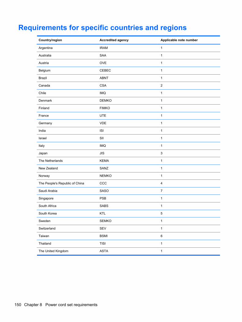
Requirements for specific countries and regions
Country/region Accredited agency Applicable note number
Argentina IRAM 1
Australia SAA 1
Austria OVE 1
Belgium CEBEC 1
Brazil ABNT 1
Canada CSA 2
Chile IMQ 1
Denmark DEMKO 1
Finland FIMKO 1
France UTE 1
Germany VDE 1
India ISI 1
Israel SII 1
Italy IMQ 1
Japan JIS 3
The Netherlands KEMA 1
New Zealand SANZ 1
Norway NEMKO 1
The People's Republic of China CCC 4
Saudi Arabia SASO 7
Singapore PSB 1
South Africa SABS 1
South Korea KTL 5
Sweden SEMKO 1
Switzerland SEV 1
Taiwan BSMI 6
Thailand TISI 1
The United Kingdom ASTA 1
150 Chapter 8 Power cord set requirements
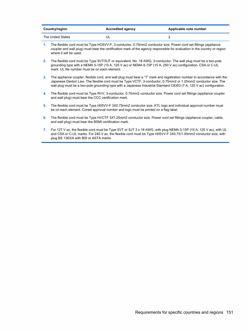
Country/region Accredited agency Applicable note number
The United States UL 2
1. The flexible cord must be Type HO5VV-F, 3-conductor, 0.75mm2 conductor size. Power cord set fittings (appliancecoupler and wall plug) must bear the certification mark of the agency responsible for evaluation in the country or regionwhere it will be used.
2. The flexible cord must be Type SVT/SJT or equivalent, No. 18 AWG, 3-conductor. The wall plug must be a two-polegrounding type with a NEMA 5-15P (15 A, 125 V ac) or NEMA 6-15P (15 A, 250 V ac) configuration. CSA or C-ULmark. UL file number must be on each element.
3. The appliance coupler, flexible cord, and wall plug must bear a “T” mark and registration number in accordance with theJapanese Dentori Law. The flexible cord must be Type VCTF, 3-conductor, 0.75mm2 or 1.25mm2 conductor size. Thewall plug must be a two-pole grounding type with a Japanese Industrial Standard C8303 (7 A, 125 V ac) configuration.
4. The flexible cord must be Type RVV, 3-conductor, 0.75mm2 conductor size. Power cord set fittings (appliance couplerand wall plug) must bear the CCC certification mark.
5. The flexible cord must be Type H05VV-F 3X0.75mm2 conductor size. KTL logo and individual approval number mustbe on each element. Corset approval number and logo must be printed on a flag label.
6. The flexible cord must be Type HVCTF 3X1.25mm2 conductor size. Power cord set fittings (appliance coupler, cable,and wall plug) must bear the BSMI certification mark.
7. For 127 V ac, the flexible cord must be Type SVT or SJT 3 x 18 AWG, with plug NEMA 5-15P (15 A, 125 V ac), with ULand CSA or C-UL marks. For 240 V ac, the flexible cord must be Type H05VV-F 3X0.75/1.00mm2 conductor size, withplug BS 1363/A with BSI or ASTA marks.
Requirements for specific countries and regions 151
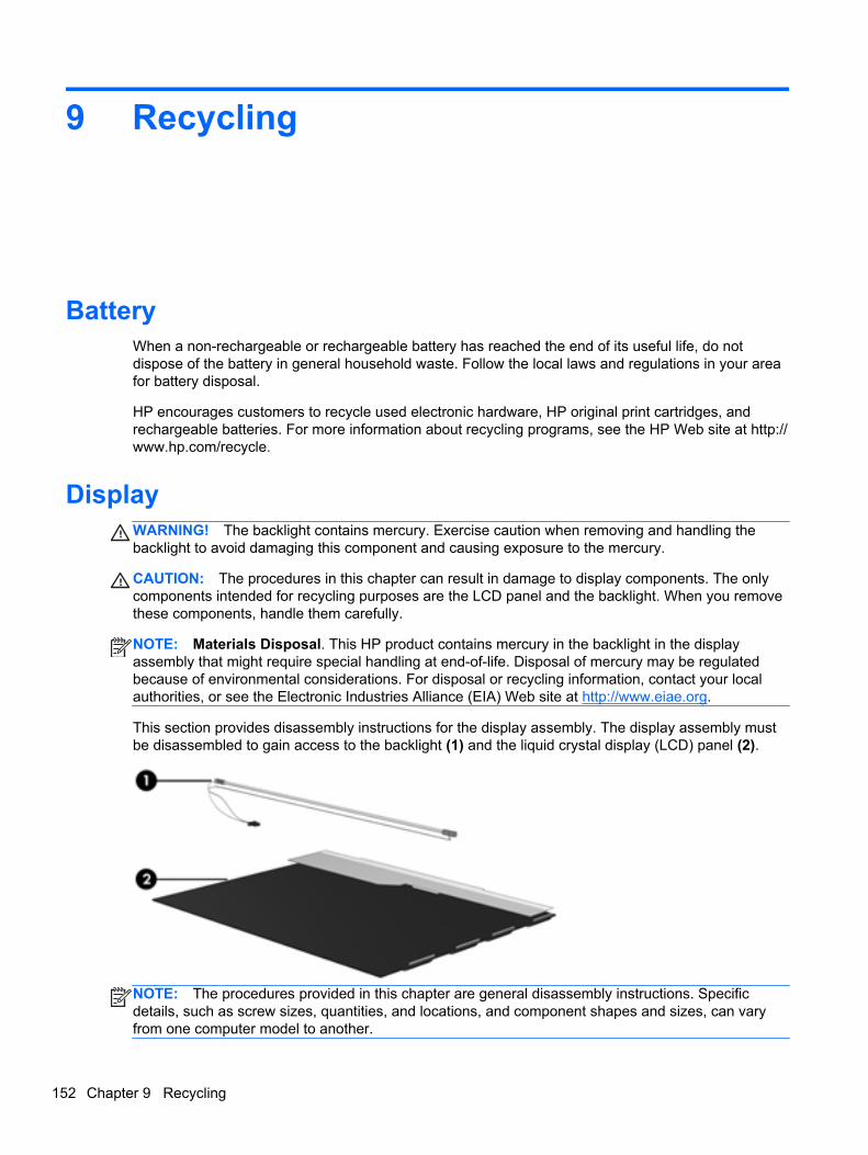
9 Recycling
BatteryWhen a non-rechargeable or rechargeable battery has reached the end of its useful life, do notdispose of the battery in general household waste. Follow the local laws and regulations in your areafor battery disposal.
HP encourages customers to recycle used electronic hardware, HP original print cartridges, andrechargeable batteries. For more information about recycling programs, see the HP Web site at http://www.hp.com/recycle.
DisplayWARNING! The backlight contains mercury. Exercise caution when removing and handling thebacklight to avoid damaging this component and causing exposure to the mercury.
CAUTION: The procedures in this chapter can result in damage to display components. The onlycomponents intended for recycling purposes are the LCD panel and the backlight. When you removethese components, handle them carefully.
NOTE: Materials Disposal. This HP product contains mercury in the backlight in the displayassembly that might require special handling at end-of-life. Disposal of mercury may be regulatedbecause of environmental considerations. For disposal or recycling information, contact your localauthorities, or see the Electronic Industries Alliance (EIA) Web site at http://www.eiae.org.
This section provides disassembly instructions for the display assembly. The display assembly mustbe disassembled to gain access to the backlight (1) and the liquid crystal display (LCD) panel (2).
NOTE: The procedures provided in this chapter are general disassembly instructions. Specificdetails, such as screw sizes, quantities, and locations, and component shapes and sizes, can varyfrom one computer model to another.
152 Chapter 9 Recycling

Perform the following steps to disassemble the display assembly:
1. Remove all screw covers (1) and screws (2) that secure the display bezel to the displayassembly.
2. Lift up and out on the left and right inside edges (1) and the top and bottom inside edges (2) ofthe display bezel until the bezel disengages from the display assembly.
3. Remove the display bezel (3).
Display 153
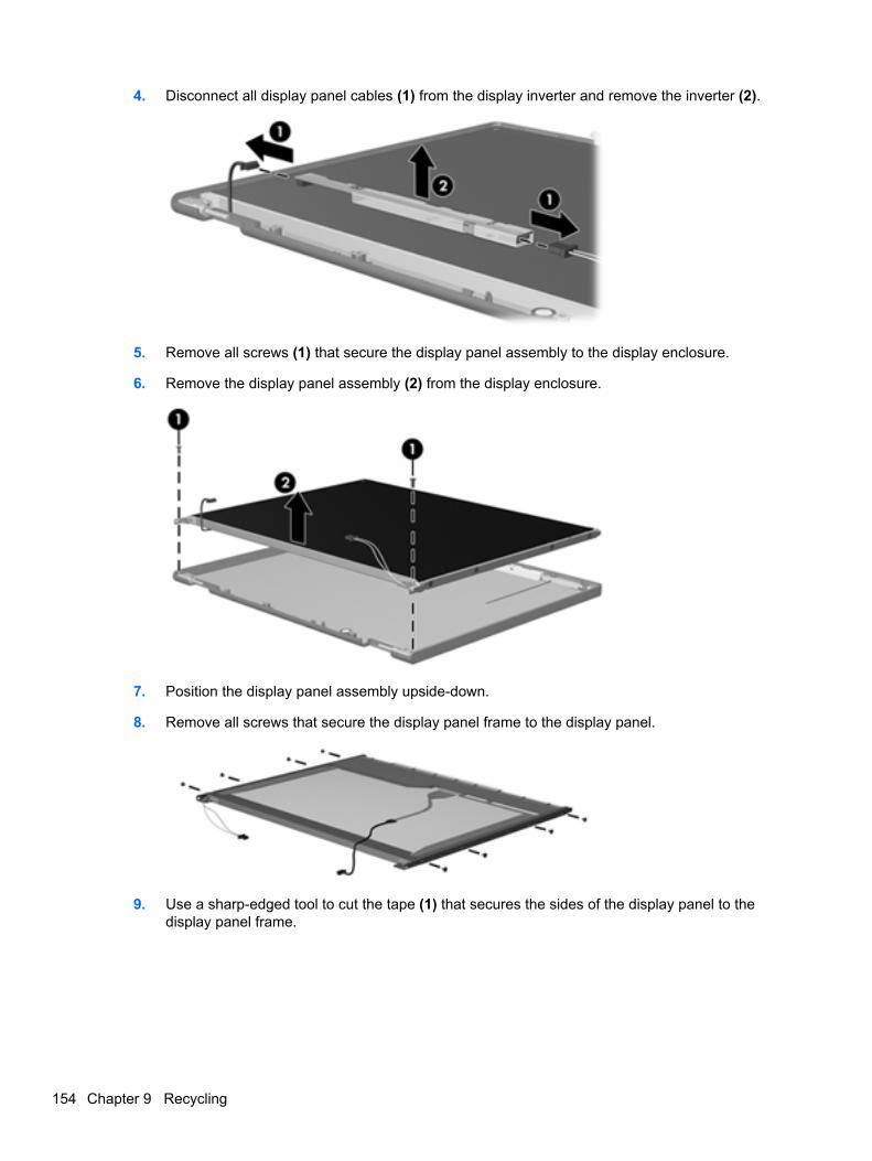
4. Disconnect all display panel cables (1) from the display inverter and remove the inverter (2).
5. Remove all screws (1) that secure the display panel assembly to the display enclosure.
6. Remove the display panel assembly (2) from the display enclosure.
7. Position the display panel assembly upside-down.
8. Remove all screws that secure the display panel frame to the display panel.
9. Use a sharp-edged tool to cut the tape (1) that secures the sides of the display panel to thedisplay panel frame.
154 Chapter 9 Recycling
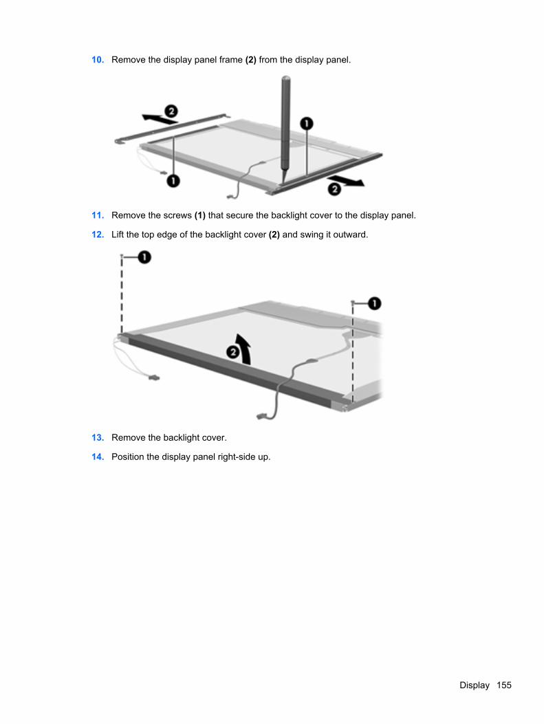
10. Remove the display panel frame (2) from the display panel.
11. Remove the screws (1) that secure the backlight cover to the display panel.
12. Lift the top edge of the backlight cover (2) and swing it outward.
13. Remove the backlight cover.
14. Position the display panel right-side up.
Display 155
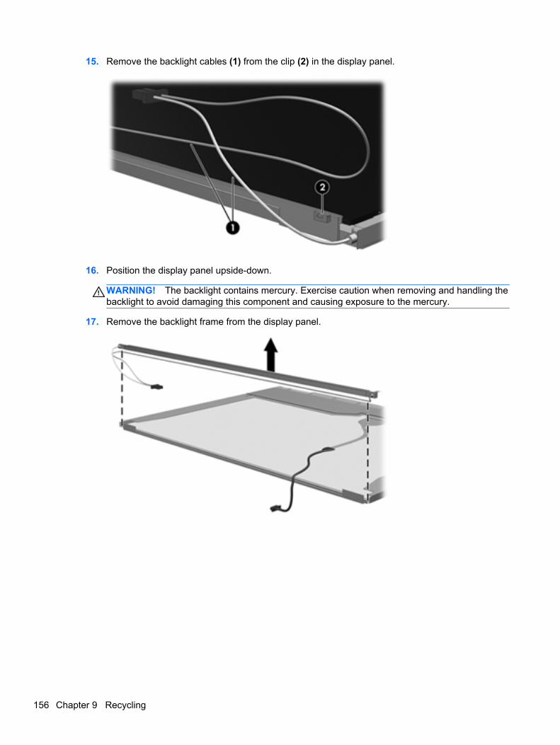
15. Remove the backlight cables (1) from the clip (2) in the display panel.
16. Position the display panel upside-down.
WARNING! The backlight contains mercury. Exercise caution when removing and handling thebacklight to avoid damaging this component and causing exposure to the mercury.
17. Remove the backlight frame from the display panel.
156 Chapter 9 Recycling
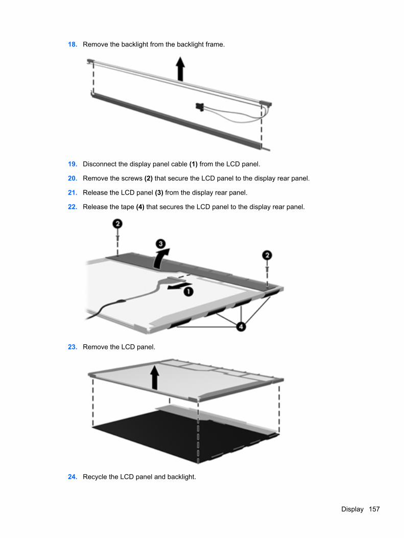
18. Remove the backlight from the backlight frame.
19. Disconnect the display panel cable (1) from the LCD panel.
20. Remove the screws (2) that secure the LCD panel to the display rear panel.
21. Release the LCD panel (3) from the display rear panel.
22. Release the tape (4) that secures the LCD panel to the display rear panel.
23. Remove the LCD panel.
24. Recycle the LCD panel and backlight.
Display 157
Index
AAC adapter light 21AC adapter, spare part numbers
38, 44access cover release latches 23advanced system diagnostics
120, 124antennas
disconnecting 62, 64audio board
removal 91spare part number 27, 31, 40,
91audio cable
illustrated 36audio, product description 3audio-in (microphone) jack 20audio-out (headphone) jack 20
Bbackup and recovery
Windows 7 136Windows 8 140
Backup and Restore 141base enclosure, spare part
number 28, 32, 40battery
removal 52spare part number 28, 32, 52
battery bay 23battery cable
removal 94spare part number 94
battery connector cable,illustrated 36
battery release latches 23BIOS
determining version 118, 123,127
downloading an update 119,123, 127
updating 117, 123, 126Blu-ray Disc ROM with SuperMulti
DVD±R/RW DL Drivespecifications 134
Blu-ray ROM DVD±RW SuperMultiDL Drive
spare part number 28, 32, 37,42, 44, 56
Bluetooth cardspare part number 64
bottom doorremoval 54spare part number 29, 33, 44,
54buttons
left TouchPad 12optical drive eject 22power 15right TouchPad 12TouchPad on/off 12Web browser 15wireless 15
CCable Kit
contents 36spare part number 36, 41, 43
cables, service considerations 47caps lock light, identifying 13chipset, product description 2components
bottom 23display 9, 11front 20left side 21right side 22top 12
computer reset 144, 148Computer Setup
navigating and selecting 115,121, 125
restoring factory settings 116,122, 126
SUSE Linux 125Windows 7 115Windows 8 121
computer setupnavigating and selecting 125restoring factory settings 126
computer specifications 129connectors, service
considerations 47
Ddiskette drive
precautions 47display assembly
removal 107spare part numbers 107
display bezelremoval 110spare part numbers 34, 41, 43
display component recycling 152display components, spare part
numbers 34display hinge
removal 113spare part number 41
Display Hinge Kitspare part numbers 34
Display Hinge Kit, spare partnumber 43
display panelproduct description 2
display specifications 130, 131drive light 20
158 Index
drivesoptical 22preventing damage 47
DVD-ROM Driveprecautions 47
DVD±RW and CD-RW Super MultiDouble-Layer Combo Drive
spare part number 32, 37, 44,56
DVD±RW and CD-RW SuperMultiDL Combo Drive
precautions 47spare part number 42
DVD±RW Double-Layer Drivespare part number 28
Eelectrostatic discharge 48embedded numeric keypad keys,
identifying 18embedded numeric keypad,
identifying 17esc key, identifying 16, 17Ethernet, product description 4external media cards, product
description 4external monitor port 21
Ff11 recovery 142fan
removal 71spare part number 29, 33, 41,
43, 71fingerprint reader assembly
spare part number 27, 31, 41,43
fingerprint reader boardremoval 85spare part number 85
fingerprint reader, identifying 15fn key, identifying 16, 17, 18, 19function board/power button board
spare part number 43function board/power button board
assemblyremoval 89spare part number 27, 31, 41,
89
function keysidentifying 16, 17, 18, 19
Ggraphics, product description 2grounding equipment and
methods 50
Hhard drive
precautions 47product description 3removal 58spare part numbers 29, 33,
37, 40, 58specifications 132
hard drive cover, removal 59hard drive extension board
removal 102spare part number 28, 41,
102Hard Drive Hardware Kit, spare
part number 37, 41, 58hard drive recovery 142HDMI port, identifying 21heat shield
removal 69spare part number 27, 32, 44,
69heat sink
removal 73spare part number 29, 33, 73
hingeremoval 113spare part number 41
Iintegrated numeric keypad,
identifying 16, 19integrated webcam light,
identifying 9, 11internal display switch 10, 11internal microphones, identifying
9, 11
Jjacks
audio-in (microphone) 20audio-out (headphone) 20network 21RJ-45 (network) 21
Kkeyboard
product description 5removal 66spare part numbers 27, 31,
41, 44, 66keypad
embedded numeric 17integrated numeric 16
keypad, integrated numeric 19keys
embedded numeric keypad18
esc 16, 17fn 16, 17, 18, 19function 16, 17, 18, 19num lk 16, 17, 18, 19operating system
applications 18, 19operating system logo key 18,
19Windows applications 16, 17Windows logo 16, 17
Llatch assembly
removal 105spare part number 105
legacy support, USB 115, 121,125
lightsAC adapter 21caps lock 13drive 20optical drive 22power 13TouchPad 13Web browser 13webcam 9, 11wireless 13
Mmass storage devices, spare part
numbers 37Media Card Reader 20memory module
product description 2removal 60spare part numbers 28, 32, 60
Index 159
microphone (audio-in) jackproduct description 3
microphone moduleremoval 112spare part number 34, 40
model name 1
Nnetwork jack, identifying 21num lk key, identifying 16, 17, 18,
19
Ooperating system applications key,
identifying 18, 19operating system logo key,
identifying 18, 19operating system, product
description 5optical drive
precautions 47product description 3removal 56spare part numbers 28, 32,
37, 56specifications 133, 134
optical drive eject button 22optical drive extension board
removal 100spare part number 27, 42,
100optical drive light 22optical drive protective insert
illustrated 35optical drive, identifying 22
Ppacking guidelines 49PCID label 25plastic parts 46Plastics Kit, spare part number
35, 43pointing device, product
description 5ports
external monitor 21HDMI 21product description 4USB 21, 22
power button, identifying 15
power cableremoval 104spare part number 104
power connector cable,illustrated 36
power connector, identifying 21power cord
set requirements 149spare part numbers 38, 39
power light 13power requirements, product
description 5processor
product description 1removal 76spare part numbers 28, 32, 76
product descriptionaudio 3chipset 2display panel 2Ethernet 4external media cards 4graphics 2hard drives 3keyboard 5memory module 2microphone 3operating system 5optical drives 3pointing devices 5ports 4power requirements 5processors 1product name 1security 5serviceability 8webcam 3wireless 4
product name 1
Rrecovery 144recovery partition 142recycle
computer 144, 148refresh 144release latches
access cover 23battery 23
removal/replacementpreliminaries 46procedures 51
remove everything and reinstallWindows 144, 148
resetcomputer 144, 148steps 144, 148
restoring the hard drive 142RJ-45 (network) jack, identifying
21RTC battery
removal 98spare part number 27, 31, 43,
98Rubber Kit, spare part number 43
SScrew Kit, spare part number 38,
43, 44Secure Digital card insert,
illustratedillustrated 35
security cable slot 21security screw
removal 53security, product description 5service considerations 46service door, identifying 23service tag 24serviceability, product
description 8setup utility
navigating and selecting 115,121
restoring factory settings 116,122
SUSE Linux 125Windows 7 115Windows 8 121
SIM, removal 55slots
security cable 21speaker assembly
removal 87spare part number 27, 32, 43,
44, 87speakers, identifying 15
160 Index
specificationsBlu-ray Disc ROM with
SuperMulti DVD±R/RW DLDrive 134
computer 129display 130, 131DVD±RW and CD-RW
SuperMulti DL Combo Drive133
hard drive 132optical drive 133, 134
static-shielding materials 50SUSE Linux
backup and recovery 145Computer Setup 125Windows 7 145
system boardremoval 95spare part numbers 27, 31,
42, 95
Tthermal material, replacement
74, 75tools required 46top cover
removal 78spare part number 27, 31, 43,
78TouchPad
buttons 12TouchPad light, identifying 13TouchPad on/off button 12TouchPad zone
identifying 12transporting guidelines 49
UUSB connector and cable
illustrated 36USB connector assembly
removal 92spare part number 92
USB legacy support 115, 121,125
USB ports, identifying 21, 22
Vvents, identifying 21, 23
WWeb browser button, identifying
15Web browser light 13webcam 11
product description 3spare part number 43
webcam light, identifying 9, 11webcam module
removal 112spare part number 34
webcam, identifying 9, 11Windows
Refresh 144reinstall 144, 148remove everything and reinstall
option 144, 148reset 144, 148
Windows 7backup and recovery 136Computer Setup 115
Windows 8backup and recovery 140Computer Setup 121
Windows 8 operating systemDVD 143
Windows applications key,identifying 16, 17
Windows logo key, identifying 16,17
wireless antennasdisconnecting 62, 64
wireless antennas, identifying 9wireless button, identifying 15wireless light 13wireless, product description 4WLAN antennas, identifying 9,
11WLAN module
spare part numbers 28, 32WLAN/Bluetooth combo card
removal 64spare part number 64
workstation guidelines 49WWAN antennas, identifying 9WWAN module
removal 62spare part number 28, 32, 40,
62
Index 161