maintenance and troubleshooting 10/2020, edition 1
TRANSCRIPT

DOC023.52.90645
BioTector B7000i Dairy Online TOC Analyzer
Maintenance and Troubleshooting
10/2020, Edition 1


Table of Contents
Section 1 Maintenance ....................................................................................................................... 31.1 Safety information........................................................................................................................ 3
1.1.1 Safety symbols and markings............................................................................................ 31.1.2 Use of hazard information................................................................................................... 41.1.3 Electrical safety precautions................................................................................................41.1.4 Ozone precautions.............................................................................................................. 4
1.2 Maintenance schedule................................................................................................................. 51.3 Weekly maintenance.................................................................................................................... 51.4 Fill or replace the reagents...........................................................................................................61.5 Replace a fuse............................................................................................................................. 61.6 Shutdown procedure.................................................................................................................... 8
1.6.1 Flush the reagent lines........................................................................................................ 9Section 2 Troubleshooting ..............................................................................................................11
2.1 System Faults............................................................................................................................ 112.2 System warnings........................................................................................................................ 132.3 Notifications................................................................................................................................192.4 Show the status history before a fault ........................................................................................ 19
Section 3 Diagnostics ...................................................................................................................... 213.1 Do a pressure test...................................................................................................................... 213.2 Do a flow test............................................................................................................................. 213.3 Do an ozone test........................................................................................................................ 223.4 Do a sample pump test.............................................................................................................. 223.5 Do a pH test............................................................................................................................... 233.6 Do a sample valve test............................................................................................................... 243.7 Do a base wash test...................................................................................................................253.8 Do simulations............................................................................................................................253.9 Do a relay or 4–20 mA output test............................................................................................. 273.10 Show the input and output status............................................................................................. 273.11 Show the oxygen controller status........................................................................................... 283.12 Show the Modbus status.......................................................................................................... 293.13 Modbus troubleshooting........................................................................................................... 29
Section 4 Analysis enclosure ......................................................................................................... 31Section 5 Control enclosure components ...................................................................................33Section 6 Replacement parts and accessories .......................................................................... 35
1

Table of Contents
2
Section 1 Maintenance
D A N G E R
Multiple hazards. Only qualified personnel must conduct the tasks described in thissection of the document.
1.1 Safety informationPlease read this entire manual before maintenance tasks or troubleshooting is done onthis equipment. Pay attention to all danger and caution statements. Failure to do so couldresult in serious injury to the operator or damage to the equipment.Make sure that the protection provided by this equipment is not impaired. Do not use orinstall this equipment in any manner other than that specified in this manual.
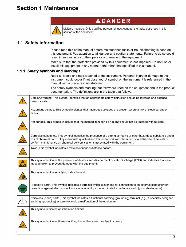
1.1.1 Safety symbols and markingsRead all labels and tags attached to the instrument. Personal injury or damage to theinstrument could occur if not observed. A symbol on the instrument is referenced in themanual with a precautionary statement.The safety symbols and marking that follow are used on the equipment and in the productdocumentation. The definitions are in the table that follows.
Caution/Warning. This symbol identifies that an appropriate safety instruction should be followed or a potentialhazard exists.
Hazardous voltage. This symbol indicates that hazardous voltages are present where a risk of electrical shockexists.
Hot surface. This symbol indicates that the marked item can be hot and should not be touched without care.
Corrosive substance. This symbol identifies the presence of a strong corrosive or other hazardous substance and arisk of chemical harm. Only individuals qualified and trained to work with chemicals should handle chemicals orperform maintenance on chemical delivery systems associated with the equipment.
Toxic. This symbol indicates a toxic/poisonous substance hazard.
This symbol indicates the presence of devices sensitive to Electro-static Discharge (ESD) and indicates that caremust be taken to prevent damage with the equipment.
This symbol indicates a flying debris hazard.
Protective earth. This symbol indicates a terminal which is intended for connection to an external conductor forprotection against electric shock in case of a fault (or the terminal of a protective earth (ground) electrode).
Noiseless (clean) earth. This symbol indicates a functional earthing (grounding) terminal (e.g., a specially designedearthing (grounding) system) to avoid a malfunction of the equipment.
This symbol indicates an inhalation hazard.
This symbol indicates there is a lifting hazard because the object is heavy.
3
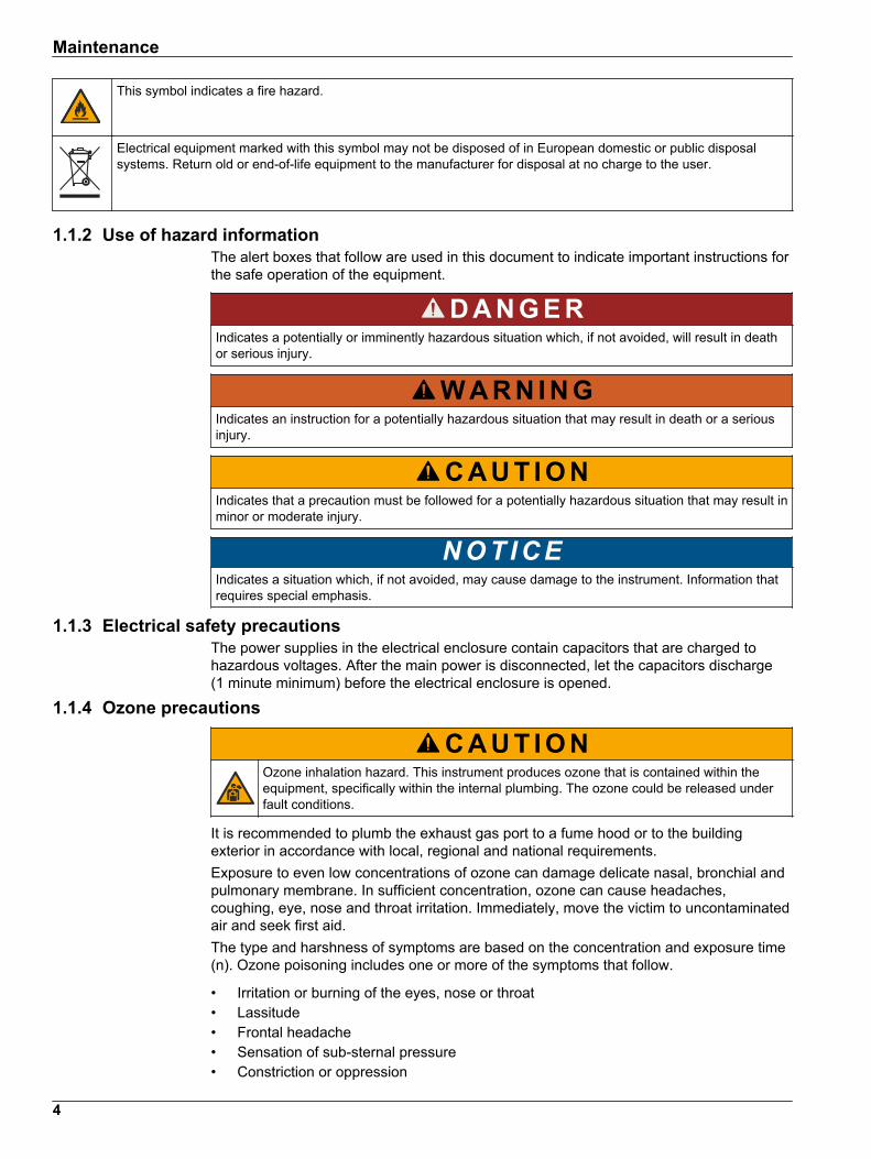
This symbol indicates a fire hazard.
Electrical equipment marked with this symbol may not be disposed of in European domestic or public disposalsystems. Return old or end-of-life equipment to the manufacturer for disposal at no charge to the user.
1.1.2 Use of hazard informationThe alert boxes that follow are used in this document to indicate important instructions forthe safe operation of the equipment.
D A N G E R
Indicates a potentially or imminently hazardous situation which, if not avoided, will result in deathor serious injury.
W A R N I N G
Indicates an instruction for a potentially hazardous situation that may result in death or a seriousinjury.
C A U T I O N
Indicates that a precaution must be followed for a potentially hazardous situation that may result inminor or moderate injury.
NOT ICE
Indicates a situation which, if not avoided, may cause damage to the instrument. Information thatrequires special emphasis.
1.1.3 Electrical safety precautionsThe power supplies in the electrical enclosure contain capacitors that are charged tohazardous voltages. After the main power is disconnected, let the capacitors discharge(1 minute minimum) before the electrical enclosure is opened.
1.1.4 Ozone precautions
C A U T I O N
Ozone inhalation hazard. This instrument produces ozone that is contained within theequipment, specifically within the internal plumbing. The ozone could be released underfault conditions.
It is recommended to plumb the exhaust gas port to a fume hood or to the buildingexterior in accordance with local, regional and national requirements.Exposure to even low concentrations of ozone can damage delicate nasal, bronchial andpulmonary membrane. In sufficient concentration, ozone can cause headaches,coughing, eye, nose and throat irritation. Immediately, move the victim to uncontaminatedair and seek first aid.The type and harshness of symptoms are based on the concentration and exposure time(n). Ozone poisoning includes one or more of the symptoms that follow.
• Irritation or burning of the eyes, nose or throat• Lassitude• Frontal headache• Sensation of sub-sternal pressure• Constriction or oppression
Maintenance
4

• Acid taste in mouth• Anorexia
In case of more severe ozone poisoning, the symptoms can include dyspnea, cough,choking sensation, tachycardia, vertigo, lowering of blood pressure, cramping, chest pain,and generalized body pain. Ozone can cause a pulmonary oedema one or more hoursafter exposure.
1.2 Maintenance schedule
NOT ICE
To prevent instrument damage, weekly maintenance must be done by a Hach trained operator orHach trained maintenance personnel.To prevent instrument damage, 6-month maintenance and troubleshooting must be done by Hachtrained maintenance personnel.
Table 1 shows the recommended schedule of maintenance tasks. Facility requirementsand operating conditions may increase the frequency of some tasks.
Table 1 Maintenance scheduleTask 1 week 6 months 12 months As necessary
Weekly maintenanceon page 5
X
6-month maintenance1 X
Fill or replace thereagents on page 6
X
Replace a fuseon page 6
X
Shutdown procedureon page 8
X
1.3 Weekly maintenanceUse the checklist that follows to complete weekly maintenance. Do the tasks in the ordergiven.
Task Initial
Select OPERATION > START,STOP > FINISH & STOP or EMERGENCY STOP.
Wait for the display to show "SYSTEM STOPPED".
Make sure that the instrument air pressure supplied to the analyzer is correct.
• Instrument air plumbed to analyzer—1.5 bar• BioTector compressor plumbed to analyzer—1.2 bar
Select MAINTENANCE > DIAGNOSTICS > SIMULATE. Select MFC. Set the flow to 20 L/h. Push to startthe mass flow controller (MFC). The measured flow shows on the display.
Make sure that the pressure regulator shows 400 mbar at 20 L/h. Refer to Analysis enclosure on page 31 forthe location.
Make sure that the reagent levels are sufficient. Fill or replace reagent containers as necessary. Refer to Fillor replace the reagents on page 6.
1 Refer to the documentation supplied with the maintenance kit for instructions.
Maintenance
5

Task Initial
Make sure that there are no leaks at the reagent pumps. Refer to Analysis enclosure on page 31 for thelocation.
Make sure that there are no leaks at the sample pump.
Make sure that there are no leaks at the valves in the analyzer. Refer to Analysis enclosure on page 31 forthe location.
Make sure that there are no blockages in the sample lines to the analyzer or the sample lines in the analyzer.
Make sure that there are no blockages in the drain lines from the analyzer or the drain lines in the analyzer.
Make sure that there is sufficient sample flow to the sample tubing for a fresh sample for each analysis cycle.
Make sure that there is no blockage in the exhaust tubing.
Make sure that there are no blockages in the filter in the fan housing and the vent housing on the left side ofthe analyzer.
If a sampler is used, make sure that the operation of the sampler is correct.
1.4 Fill or replace the reagents
C A U T I O N
Chemical exposure hazard. Obey laboratory safety procedures and wear all of thepersonal protective equipment appropriate to the chemicals that are handled. Refer tothe current safety data sheets (MSDS/SDS) for safety protocols.
C A U T I O N
Chemical exposure hazard. Dispose of chemicals and wastes in accordance with local,regional and national regulations.
Fill or replace the reagent containers as necessary when the analyzer is in operation orstopped.
1. Fill or replace the reagents.2. Select MAINTENANCE > COMMISSIONING > REAGENTS MONITOR.3. Set the reagents volumes.4. If the acid or base are filled or replaced, select OPERATION > REAGENTS SETUP>
INSTALL NEW REAGENTS to prime the reagent tubing and do a zero calibration.
1.5 Replace a fuse
D A N G E R
Electrocution hazard. Isolate all power to the instrument and disconnect all power fromthe instrument and relay connections before this maintenance task is started
D A N G E R
Electrocution hazard. Use the same type and current rating to replace fuses.
Replace a blown fuse for correct operation. Refer to Figure 1 for the fuse locations. Referto Table 2 for the fuse specifications.In addition, a diagram of the fuse locations is available on the top door.
Maintenance
6

Figure 1 Fuse location diagram
Table 2 Fuse specificationsItem Location Name PCB ID Number Size Material Fuse
NumberCurrentRating
Type
1 Cooler DIN rail Terminal 47 Miniature5 x 20 mm
Ceramic F1 2.5 A (DC) T 2.5A H250V
2 Relay PCB 81204001-03 Miniature5 x 20 mm
Glass F1 2.5 A (DC) T 2.5 A L125V DC
F2 0.5 A (DC) T 500mA L 125VDC
F3 0.5 A (DC) T 500mA L 125VDC
F4 1.0 A (DC) T 1A L125 V DC
F5 1.0 A (DC) T 1A L125 V DC
F6 1.0 A (DC) T 1A L125 V DC
F7 1.0 A (DC) T 1A L125 V DC
F8 1.0 A (DC) T 1A L125 V DC
Maintenance
7

Table 2 Fuse specifications (continued)Item Location Name PCB ID Number Size Material Fuse
NumberCurrentRating
Type
3 115 VAC Power PCB(Mains PCB)
81204030-03 Miniature5 x 20 mm
Ceramic F1 T 2.5 A T 2.50A H250V
F2 0.5 A T 500 mA H250V
F3 1.0 A T 1A H250V
F4 2.5 A T 2.50A H250V
F5 3.15 A T 3.15A H250V
F6 0.5 A T 500mA H250V
4 230 VAC Power PCB(Mains PCB)
81204030-03 Miniature5 x 20 mm
Ceramic F1 T 2.5 A T 2.50A H250V
F2 0.5 A T 500mA H250V
F3 1.0 A T 1A H250V
F4 1.6 A T 1.60A H250V
F5 2.0 A T 2A H250V
F6 0.5 A T 500mA H250V
5 Main board(Motherboard)
81204022-09 Miniature5 x 20 mm
Glass F1 0.5 A (DC) T 500mA L125VDC
6 Signal PCB 81204010-02 Miniature5 x 20 mm
Glass F1 1.0 A (DC) T 1A L125V DC
F3 0.5 (DC) T 500mA L125VDC
7 Stream Expansion PCB 81204040-02 Miniature5 x 20 mm
Glass F1 1.0 A (DC) T 1A L125V DC
Key:A—AmperesF—FuseH—High interruptID—IdentificationL— Low interruptmA—MilliamperesPCB—Printed circuit boardT—Time lag (time delay)V—Volts
1.6 Shutdown procedureIf power will be removed from the analyzer for more than 2 days, use the checklist thatfollows to prepare the analyzer for shutdown or storage. Do the tasks in the order given.
Task Initial
Select OPERATION > START,STOP > FINISH & STOP or EMERGENCY STOP.
Wait for the display to show "SYSTEM STOPPED".
Remove the reagent from the reagent lines for safety. Refer to Flush the reagent lines on page 9.
Disconnect the SAMPLE fittings from the sample sources. Connect the SAMPLE fittings to an open drain orempty plastic container.
Maintenance
8

Task Initial
Set the power switch in the analyzer to off.
Set the power disconnect device for the analyzer to off.
1.6.1 Flush the reagent lines
C A U T I O N
Chemical exposure hazard. Obey laboratory safety procedures and wear all of thepersonal protective equipment appropriate to the chemicals that are handled. Refer tothe current safety data sheets (MSDS/SDS) for safety protocols.
C A U T I O N
Chemical exposure hazard. Dispose of chemicals and wastes in accordance with local,regional and national regulations.
Remove the reagent from the reagent lines for safety.
1. Put on the personal protective equipment identified in the safety data sheets(MSDS/SDS).
2. Remove the tubes from the ACID and BASE ports on the side of the analyzer.3. Plumb the ACID and BASE ports to a deionized water container. If deionized water is
not available, use tap water.4. Select CALIBRATION > ZERO CALIBRATION > RUN REAGENTS PURGE to start a
purge cycle.5. Do step 4 again.
The analyzer replaces the reagents in the reagents lines with water.6. When the reagent purge cycle is complete, remove the tubing from the deionized
water container and put them in open air.7. Do step 4 two times.
The analyzer replaces the water in the reagents lines with air.
Maintenance
9

Maintenance
10

Section 2 Troubleshooting
2.1 System FaultsSelect OPERATION > FAULT ARCHIVE to see the system faults that have occurred.Faults and warnings with an asterisk (*) are active.
When "SYSTEM FAULT" shows in the top-left corner of the Reaction Data screen or theReagent Status screen, a system fault has occurred. Measurements have stopped. The4–20 mA outputs are set to the fault level (default: 1 mA). The system fault relay (Relay20) is set to on.To start the analyzer again, complete the troubleshooting steps for the system fault. Referto Table 3. To acknowledge the fault, select the fault and push .Note: There are system faults (e.g., 05_Pressure Test Fail) that cannot be acknowledged by theuser. These faults are reset and acknowledged automatically by the system when the system isstarted, the system is rebooted or when the fault condition is removed.
Table 3 System FaultsMessage Description Cause and solution
01_LOW O2 FLOW - EX The oxygen flow through the exhaust(EX) valve was less than 50% of theoxygen flow MFC (mass flowcontroller) setpoint for more than theLOW O2 FLOW TIME setting.Refer to MAINTENANCE > SYSTEMCONFIGURATION > FAULT SETUP >LOW O2 FLOW TIME.
• Oxygen supply problem. The oxygen pressure shouldbe 400 mbar (±10 mbar) at 20 L/h MFC flow. SelectMAINTENANCE > DIAGNOSTICS > O2-CTRLSTATUS.
• Blockage in the ozone destructor• Blockage in the tube after the MFC• Failure of or blockage in the exhaust valve• Failure of the MFC. Do a flow test. Refer to Do a flow
test on page 21.
02_LOW O2 FLOW -SO
The oxygen flow through the sampleout valve (MV5) was less than 50% ofthe MFC setpoint for more than theLOW O2 FLOW TIME setting.Refer to MAINTENANCE > SYSTEMCONFIGURATION > FAULT SETUP >LOW O2 FLOW TIME.
• Oxygen supply problem. The oxygen pressure shouldbe 400 mbar (±10 mbar) at 20 L/h MFC flow. SelectMAINTENANCE > DIAGNOSTICS > O2-CTRLSTATUS.
• Failure of or blockage in the sample out valve• Failure of or blockage in the exhaust valve (MV1)• Failure of the MFC. Do a flow test. Refer to Do a flow
test on page 21.
03_HIGH O2 FLOW The oxygen flow through the exhaustvalve was more than 50% of the MFCsetpoint for more than the HIGHO2 FLOW TIME setting.Refer to MAINTENANCE > SYSTEMCONFIGURATION > FAULT SETUP >HIGH O2 FLOW TIME.
• Failure of the MFC• Oxygen pressure is too high
04_NO REACTION(can be set as a fault orwarning)
No TOC (or TC) CO2 peak or the CO2peak is less than the CO2 LEVELsetting for three consecutive reactions.Refer to MAINTENANCE > SYSTEMCONFIGURATION > REACTIONCHECK > CO2 LEVEL.
• The acid reagent and/or base reagent are theincorrect concentration.
• The acid reagent container and/or base reagentcontainer are empty.
• The acid and/or base reagent lines have a blockageor air bubbles.
• The operation of the acid pump and/or base pump isincorrect.
• The operation of the mixer reactor is incorrect. Do apH test. Refer to Do a pH test on page 23.
11

Table 3 System Faults (continued)Message Description Cause and solution
05_PRESSURE TESTFAIL
The MFC flow did not decrease to lessthan the PRESSURE TEST FAULTsetting during the pressure test.Refer to MAINTENANCE > SYSTEMCONFIGURATION > SEQUENCEPROGRAM > PRESSURE/FLOWTEST > PRESSURE TEST FAULT.
• The analyzer has a gas and/or liquid leak.• A valve has a leak.
Examine the sample out valve, sample (ARS) valve andanalyzer fittings for leaks. Examine the mixer reactor forleaks. Do a pressure test. Refer to Do a pressure teston page 21.
06_PRESSURE CHCKFAIL
The MFC flow did not decrease to lessthan the PRESSURE CHCK FAULTsetting during the pressure check forthree consecutive reactions (default).Refer to MAINTENANCE > SYSTEMCONFIGURATION > SEQUENCEPROGRAM > PRESSURE/FLOWTEST > PRESSURE CHCK FAULT.
08_RELAY PCB FAULT • 81204001 relay board has ablown fuse.
• 81204010 signal board has ablown fuse, F3.
• The operation of the 24V PSU isincorrect.
Examine the 24V DC input power. Examine the fuses onthe relay board. Refer to Control enclosure componentson page 33 for the location. Examine the fuse F3 on thesignal board.LED 6 on the signal board is set to off when the fault iscorrected.
09_OZONE PCBFAULT
The operation of the ozone board isincorrect.
Replace the ozone board. Refer to Control enclosurecomponents on page 33 for the location. Contact thetechnical support.
11_CO2 ANALYZERFAULT
The operation of the CO2 analyzer isincorrect.
Examine the 24V DC input power to the CO2 analyzerfrom the motherboard (wires 101 and 102). Refer to Control enclosure components on page 33 for thelocation.Examine the signal from the CO2 analyzer. Open the CO2analyzer and clean the lenses.For more tests, refer to the information sheet T019.BioTector CO2 Analyzer Troubleshooting.
12_HIGH CO2 IN O2 There is a high level of CO2 in theinput oxygen gas.
Select MAINTENANCE > DIAGNOSTICS > SIMULATE. Ifthe CO2 value on the display is more than 250 to300 ppm, examine the oxygen purity.Identify if there is CO2 contamination in the oxygensupply. Refer to Examine the oxygen supply in theOperation and Installation Manual.If the oxygen purity is sufficient, open the CO2 analyzerand clean the lenses. If the problem continues, replacethe CO2 analyzer filters.If the oxygen purity is not satisfactory, replace the oxygenconcentrator/bottle.
13_SMPL VALVE SENSEQ
The sample valve sensors are in awrong sequence. The sample valvesensors should be in the sequenceSensor 1, 2, 3 and 4.
Make sure that the switches 1 and 2 are both at the on(4 sensors) position on the sample valve sensor PCB.Identify if faults 14_SAMPLE VALVE SEN1, 15_SAMPLEVALVE SEN2 or 16_SAMPLE VALVE SEN3 haveoccurred.Examine fuse F6 on the Relay PCB. SelectMAINTENANCE > DIAGNOSTICS > SAMPLE VALVE.Examine the operation of the sample valve. Examine thesample valve sensor wiring.
Troubleshooting
12

Table 3 System Faults (continued)Message Description Cause and solution
14_SAMPLE VALVESEN115_SAMPLE VALVESEN216_SAMPLE VALVESEN3130_SAMPLE VALVESEN4
Sample Valve Sensor 1, 2, 3 or 4 didnot show the position of the valve.
Examine fuse F6 on the Relay PCB. The operation of thesample valve sensors is incorrect or there is anorientation problem. Examine the wiring on the valveboard and on the Signal PCB. Refer to Control enclosurecomponents on page 33 for the location.Examine the sensor signals. Look at LEDs 12, 13 and14 on the Signal PCB and DI01, DI02 and DI03 in theDIGITAL INPUT menu. Select MAINTENANCE >DIAGNOSTICS > INPUT/OUTPUT STATUS > DIGITALINPUT for sensors 1, 2 and 3. Refer to Control enclosurecomponents on page 33 for the board location.Look at LEDs 12 and 13 on the Signal PCB and DI01 andDI02, which are on for sensor 4.Replace the valve assembly.
17_SMPL VALVE NOTSYNC
The correct sensor position (Sensor 1)was not identified in the sample valvewhen the sample pump is in operation.
Replace Relay 4 on the Relay PCB. Refer to Controlenclosure components on page 33 for the location.Examine the sensor signal. Look at LED 12 on the signalboard and DI01 in DIGITAL INPUT menu. SelectMAINTENANCE > DIAGNOSTICS > INPUT/OUTPUTSTATUS > DIGITAL INPUT. Refer to Control enclosurecomponents on page 33 for the board location.Select MAINTENANCE > DIAGNOSTICS > SAMPLEVALVE. Examine the sample valve SEN1 position andSEN1 signal.For more tests, refer to the information sheets T018.BioTector Sample Valve Not Synchronized FaultTroubleshooting and TT002. BioTector Sample Valve NotSync Fault Quick Troubleshooting.
18_LIQUID LEAK DET The liquid leak detector in the analyzeris active. There is a liquid leak.
Look for a liquid leak in the analyzer enclosure.Disconnect the leak detector connector on the bottom ofthe reactor to identify if the reactor has a leak. Examinethe liquid leak detector.
20_NO REAGENTS(can be set as a fault,warning or notification)
The calculated reagent levels identifythat the reagent containers are empty.
Replace the reagents. Refer to Fill or replace thereagents on page 6.
129_REACT PURGEFAIL
There is a blockage in the reactor,sample out valve or the associatedtubing and fittings. The MFC operationis not correct or the MFC tubing has ablockage.
There is an air or oxygen supply problem. Look at the O2-CTRL STATUS menu to examine the oxygen pressure.The pressure is normally 400 mbar (±10 mbar) at 20 L/hMFC flow.Do a flow test. Refer to Do a flow test on page 21.
2.2 System warningsSelect OPERATION > FAULT ARCHIVE to see the warnings that have occurred. Faultsand warnings with an asterisk (*) are active.
When "SYSTEM WARNING" shows in the top-left corner of the Reaction Data screen orthe Reagent Status screen, a warning has occurred. Measurements continue. The4-20 mA outputs do not change. The system fault relay (Relay 20) is not set to on.Complete the troubleshooting steps for the warning. Refer to Table 4. To acknowledgethe warning, select the warning and push .If there are multiple warnings in the instrument, examine the fuses on the relay board andsignal board.
Troubleshooting
13

Table 4 System warningsMessage Description Cause and solution
21_CO2 ANL LENSDIRTY
The optical device of the CO2 analyzer isdirty.
Clean the CO2 analyzer. Clean the lenses in the CO2analyzer.
22_FLOW WARNING –EX
The oxygen flow through the exhaustvalve (MV1) has decreased to less thanthe FLOW WARNING setting during thepressure test.Refer to MAINTENANCE > SYSTEMCONFIGURATION > SEQUENCEPROGRAM > PRESSURE/FLOW TEST >FLOW WARNING.
• Oxygen cylinder is empty• Oxygen supply problem. The oxygen pressure
should be 400 mbar (±10 mbar) at 20 L/h MFCflow. Select MAINTENANCE > DIAGNOSTICS >O2-CTRL STATUS.
• Blockage in the ozone destructor• Blockage in the tube after the mass flow
controller (MFC)• Failure of or blockage in the exhaust valve• Failure of the MFC. Do a flow test. Refer to Do a
flow test on page 21.
23_FLOW WARNING –SO
The oxygen flow through the sample outvalve (MV5) has decreased to less thanthe FLOW WARNING setting during thepressure test.Refer to MAINTENANCE > SYSTEMCONFIGURATION > SEQUENCEPROGRAM > PRESSURE/FLOW TEST >FLOW WARNING.
• Oxygen cylinder is empty• Oxygen supply problem. The oxygen pressure
should be 400 mbar (±10 mbar) at 20 L/h MFCflow. Select MAINTENANCE > DIAGNOSTICS >O2-CTRL STATUS.
• Failure of or blockage in the sample out valve• Blockage in the tube after MFC• Failure of the MFC. Do a flow test. Refer to Do a
flow test on page 21.
26_PRESSURE TESTWARN
The MFC flow did not decrease to lessthan the PRESSURE TEST WARNsetting during the pressure test.Refer to MAINTENANCE > SYSTEMCONFIGURATION > SEQUENCEPROGRAM > PRESSURE/FLOW TEST >PRESSURE TEST WARN.
• The analyzer has a gas and/or liquid leak.• A valve has a leak.
Examine the sample out valve, sample (ARS) valveand analyzer fittings for leaks. Examine the mixerreactor for leaks. Do a pressure test. Refer to Do apressure test on page 21.
28_NO PRESSURETEST
The pressure test was not done during thesystem startup sequence.Note: The warning stays active until a pressuretest is passed.
The analyzer was started with a quick startup. TheRIGHT arrow key was pushed when START wasselected.
29_PRESSURE TESTOFF
The pressure test and flow test functionsare set to off.
Set the pressure test and flow test functions to on inthe MAINTENANCE > SYSTEM CONFIGURATION> SEQUENCE PROGRAM > PRESSURE/FLOWTEST menu.
30_TOC SPAN CAL FAIL31_TIC SPAN CAL FAIL
The result of the TIC or TOC spancalibration is not within the TIC BAND orTOC BAND setting.Refer to MAINTENANCE > SYSTEMCONFIGURATION > SEQUENCEPROGRAM > SPAN PROGRAM > TICBAND or TOC BAND.
Make sure that the concentration of the preparedstandard solution is correct. Make sure that thesettings in the CALIBRATION > SPANCALIBRATION menu are correct. Examine theoperation of the analyzer.
33_TOC SPAN CHCKFAIL34_ TIC SPAN CHCKFAIL
The result of the TIC or TOC span checkis not within the TIC BAND or TOC BANDsetting.Refer to MAINTENANCE > SYSTEMCONFIGURATION > SEQUENCEPROGRAM > SPAN PROGRAM > TICBAND or TOC BAND.
Troubleshooting
14
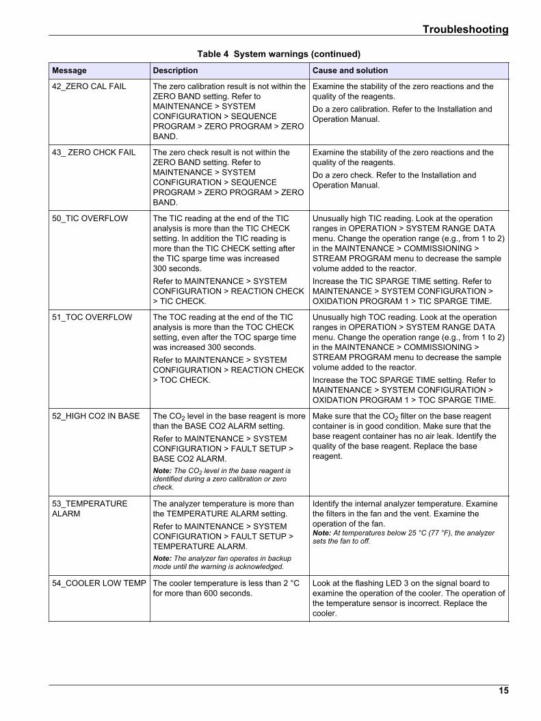
Table 4 System warnings (continued)Message Description Cause and solution
42_ZERO CAL FAIL The zero calibration result is not within theZERO BAND setting. Refer toMAINTENANCE > SYSTEMCONFIGURATION > SEQUENCEPROGRAM > ZERO PROGRAM > ZEROBAND.
Examine the stability of the zero reactions and thequality of the reagents.Do a zero calibration. Refer to the Installation andOperation Manual.
43_ ZERO CHCK FAIL The zero check result is not within theZERO BAND setting. Refer toMAINTENANCE > SYSTEMCONFIGURATION > SEQUENCEPROGRAM > ZERO PROGRAM > ZEROBAND.
Examine the stability of the zero reactions and thequality of the reagents.Do a zero check. Refer to the Installation andOperation Manual.
50_TIC OVERFLOW The TIC reading at the end of the TICanalysis is more than the TIC CHECKsetting. In addition the TIC reading ismore than the TIC CHECK setting afterthe TIC sparge time was increased300 seconds.Refer to MAINTENANCE > SYSTEMCONFIGURATION > REACTION CHECK> TIC CHECK.
Unusually high TIC reading. Look at the operationranges in OPERATION > SYSTEM RANGE DATAmenu. Change the operation range (e.g., from 1 to 2)in the MAINTENANCE > COMMISSIONING >STREAM PROGRAM menu to decrease the samplevolume added to the reactor.Increase the TIC SPARGE TIME setting. Refer toMAINTENANCE > SYSTEM CONFIGURATION >OXIDATION PROGRAM 1 > TIC SPARGE TIME.
51_TOC OVERFLOW The TOC reading at the end of the TICanalysis is more than the TOC CHECKsetting, even after the TOC sparge timewas increased 300 seconds.Refer to MAINTENANCE > SYSTEMCONFIGURATION > REACTION CHECK> TOC CHECK.
Unusually high TOC reading. Look at the operationranges in OPERATION > SYSTEM RANGE DATAmenu. Change the operation range (e.g., from 1 to 2)in the MAINTENANCE > COMMISSIONING >STREAM PROGRAM menu to decrease the samplevolume added to the reactor.Increase the TOC SPARGE TIME setting. Refer toMAINTENANCE > SYSTEM CONFIGURATION >OXIDATION PROGRAM 1 > TOC SPARGE TIME.
52_HIGH CO2 IN BASE The CO2 level in the base reagent is morethan the BASE CO2 ALARM setting.Refer to MAINTENANCE > SYSTEMCONFIGURATION > FAULT SETUP >BASE CO2 ALARM.Note: The CO2 level in the base reagent isidentified during a zero calibration or zerocheck.
Make sure that the CO2 filter on the base reagentcontainer is in good condition. Make sure that thebase reagent container has no air leak. Identify thequality of the base reagent. Replace the basereagent.
53_TEMPERATUREALARM
The analyzer temperature is more thanthe TEMPERATURE ALARM setting.Refer to MAINTENANCE > SYSTEMCONFIGURATION > FAULT SETUP >TEMPERATURE ALARM.Note: The analyzer fan operates in backupmode until the warning is acknowledged.
Identify the internal analyzer temperature. Examinethe filters in the fan and the vent. Examine theoperation of the fan.Note: At temperatures below 25 °C (77 °F), the analyzersets the fan to off.
54_COOLER LOW TEMP The cooler temperature is less than 2 °Cfor more than 600 seconds.
Look at the flashing LED 3 on the signal board toexamine the operation of the cooler. The operation ofthe temperature sensor is incorrect. Replace thecooler.
Troubleshooting
15

Table 4 System warnings (continued)Message Description Cause and solution
55_COOLER HIGHTEMP
The cooler temperature is 5 °C (9 °F)more than the cooler setpoint temperatureand more than 8 °C (14 °F) below theambient temperature for more than600 seconds.
Look at the flashing LED 3 on the signal board toexamine the operation of the cooler. The operation ofthe temperature sensor or cooler peltier element isincorrect. The current received by the peltier elementshould be approximately 1.4 A. Replace the cooler.For more tests, refer to the information sheet T022.BioTector Cooler Troubleshooting.
62_SMPL PUMP STOPON
The sample pump stopped with itsrotation sensor set to on or the operationof the rotation sensor is incorrect(continuously on).ON = LED 15 is on (signal board)
Examine the rotation of the sample pump.Replace Relay 2 on the relay board.Examine the pump sensor signal. Look at LED 15 onthe signal board and DI04 in the DIGITAL INPUTmenu. Refer to MAINTENANCE > DIAGNOSTICS >INPUT/OUTPUT STATUS > DIGITAL INPUT.Replace the pump.For more tests, refer to the information sheet TT001.BioTector Sample Pump Stop On and OffWarning_Quick Troubleshooting.
63_SMPL PUMP STOPOFF
The sample pump stopped with itsrotation sensor set to off or the operationof the rotation sensor is incorrect (norotation sensed).OFF = LED 15 is off (signal board)
64_ACID PUMP STOPON
The acid pump stopped with its rotationsensor on or the operation of the rotationsensor is incorrect (continuously on).ON = LED 16 is on (signal board)
Examine the rotation of the acid pump.Examine the pump sensor signal. Look at LED 16 onthe signal board and DI05 in the DIGITAL INPUTmenu. Refer to MAINTENANCE > DIAGNOSTICS >INPUT/OUTPUT STATUS > DIGITAL INPUT.Replace the pump.65_ACID PUMP STOP
OFFThe acid pump stopped with its rotationsensor off or the operation of the rotationsensor is incorrect (no rotation sensed).OFF = LED 16 is off (signal board)
66_BASE PUMP STOPON
The base pump stopped with its rotationsensor on or the operation of the rotationsensor is incorrect (continuously on).ON = LED 17 is on (signal board)
Examine the rotation of the base pump.Examine the pump sensor signal. Look at LED 17 onthe signal board and DI06 in the DIGITAL INPUTmenu. Refer to MAINTENANCE > DIAGNOSTICS >INPUT/OUTPUT STATUS > DIGITAL INPUT.Replace the pump.67_BASE PUMP STOP
OFFThe base pump stopped with its rotationsensor off or the operation of the rotationsensor is incorrect (no rotation sensed).OFF = LED 17 is off (signal board)
81_ATM PRESSUREHIGH
The reading of the atmospheric pressuresensor is more than 115 kPa. Theatmospheric pressure sensor reading isset to 101.3 kPa (fault operation mode).
Examine ADC[8] in the ANALOG INPUT menu.Refer to MAINTENANCE > DIAGNOSTICS >INPUT/OUTPUT STATUS > ANALOG INPUT. Thereading should be approximately 4 V.The operation of the pressure sensor is incorrect.Replace the motherboard.
82_ATM PRESSURELOW
The reading of the atmospheric pressuresensor is less than 60 kPa. Theatmospheric pressure sensor reading isset to 101.3 kPa (fault operation mode).
83_SERVICE TIME Service is necessary (200 day interval) Complete the necessary service tasks. Then, resetthe service counter to acknowledge the warning.Select MAINTENANCE > DIAGNOSTICS >SERVICE > RESET SERVICE COUNTER.
84_SAMPLER ERROR There is no/low sample or low airpressure/vacuum in the sampler.
Examine the LCD screen of the sampler for moreinformation. Refer to the sampler user manual.
Troubleshooting
16
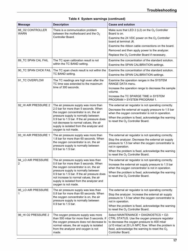
Table 4 System warnings (continued)Message Description Cause and solution
88_O2 CONTROLLERWARN
There is a communication problembetween the motherboard and the O2Controller Board.
Make sure that LED 2 (L2) on the O2 ControllerBoard is on.Examine the 24 VDC power on the O2 Controllerboard at terminal J6.Examine the ribbon cable connections on the board.Removed and then apply power to the analyzer.Replace the O2 Controller Board if necessary.
89_TC SPAN CAL FAIL The TC span calibration result is notwithin the TC BAND setting.
Examine the concentration of the standard solution.Examine the SPAN CALIBRATION settings.
90_TC SPAN CHCK FAIL The TC span check result is not within theTC BAND setting.
Examine the concentration of the standard solution.Examine the SPAN CALIBRATION settings.
91_TC OVERFLOW The TC readings are high even after theTC time was extended to the maximumtime of 300 seconds.
Examine the operation ranges in the SYSTEMRANGE DATA menu.Increase the operation range to decrease the samplevolume.Increase the TC SPARGE TIME in SYSTEMPROGRAM > SYSTEM PROGRAM 1.
92_HI AIR PRESSURE 2 The air pressure supply was more than2.0 bar for more than 5 seconds. Whenthe oxygen concentrator is on, the airpressure supply is normally between0.9 bar to 1.5 bar. If the air pressure doesnot decrease to normal values, the airsupply is isolated from the analyzer andoxygen is not made.
The external air regulator is not operating correctly.Decrease the external air supply pressure to 1.5 barwhen the oxygen concentrator is not in operation.When the problem is fixed, acknowledge the warningto reset the O2 Controller Board.
93_HI AIR PRESSURE 1 The air pressure supply was more than1.8 bar for more than 60 seconds. Whenthe oxygen concentrator is on, the airpressure supply is normally between0.9 bar to 1.5 bar.
The external air regulator is not operating correctly.Stop the analyzer. Decrease the external air supplypressure to 1.5 bar when the oxygen concentrator isnot in operation.When the problem is fixed, acknowledge the warningto reset the O2 Controller Board.
94_LO AIR PRESSURE2
The air pressure supply was less than0.6 bar for more than 5 seconds. Whenthe oxygen concentrator is on, the airpressure supply is normally between0.9 bar to 1.5 bar. If the air pressure doesnot increase to normal values, the airsupply is isolated from the analyzer andoxygen is not made.
The external air regulator is not operating correctly.Increase the external air supply pressure to 1.5 barwhen the oxygen concentrator is not in operation.When the problem is fixed, acknowledge the warningto reset the O2 Controller Board.
95_LO AIR PRESSURE1
The air pressure supply was less than0.8 bar for more than 60 seconds. Whenthe oxygen concentrator is on, the airpressure supply is normally between0.9 bar to 1.5 bar.
The external air regulator is not operating correctly.Stop the analyzer. Increase the external air supplypressure to 1.5 bar when the oxygen concentrator isnot in operation.When the problem is fixed, acknowledge the warningto reset the O2 Controller Board.
96_HI O2 PRESSURE 2 The oxygen pressure supply was morethan 500 mbar for more than 5 seconds. Ifthe oxygen pressure does not decrease tonormal values, the air supply is isolatedfrom the analyzer and oxygen is notmade.
Select MAINTENANCE > DIAGNOSTICS > O2-CTRL STATUS. Use the oxygen pressure regulatorto decrease the oxygen pressure to 400 mbar(±10 mbar) at 20 L/h MFC flow. When the problem isfixed, acknowledge the warning to reset the O2Controller Board.
Troubleshooting
17

Table 4 System warnings (continued)Message Description Cause and solution
97_HI O2 PRESSURE 1 The oxygen pressure supply was morethan 450 mbar for more than 60 seconds.If the oxygen pressure does not decreaseto normal values, the air supply is isolatedfrom the analyzer and oxygen is notmade.
Select MAINTENANCE > DIAGNOSTICS > O2-CTRL STATUS. Use the oxygen pressure regulatorto decrease the oxygen pressure to 400 mbar(±10 mbar) at 20 L/h MFC flow.
98_LO O2 PRESSURE 2 The oxygen pressure supply was lessthan 150 mbar for more than 5 seconds. Ifthe oxygen pressure does not increase tonormal values, the air supply is isolatedfrom the analyzer and oxygen is notmade.
Select MAINTENANCE > DIAGNOSTICS > O2-CTRL STATUS. Use the oxygen pressure regulatorto increase the oxygen pressure to 400 mbar(±10 mbar) at 20 L/h MFC flow. When the problem isfixed, acknowledge the warning to reset the O2Controller Board.
99_LO O2 PRESSURE 1 The oxygen pressure supply was lessthan 200 mbar for more than 60 seconds.If the oxygen pressure does not decreaseto normal values, the air supply is isolatedfrom the analyzer and oxygen is notmade.
Select MAINTENANCE > DIAGNOSTICS > O2-CTRL STATUS. Use the oxygen pressure regulatorto increase the oxygen pressure to 400 mbar(±10 mbar) at 20 L/h MFC flow.
100_ROTARY VSTOP:ON
The rotary valve stopped with the rotationsensor on (sensor signal 1). The sensor itnot operating correctly because it alwaysshows on (sensor signal 1).
Select MAINTENANCE > DIAGNOSTICS >SIMULATE > MFC. Set the MFC to 20 L/h. Examinethe rotation of the rotary valve. SelectMAINTENANCE > DIAGNOSTICS > O2-CTRLSTATUS. Look at the rotary valve signals (1 = on,0 = off) as the valve rotates.Replace the rotary valve.When the warning is gone, the green LED (Stepper)on the Oxygen PCB is on.
101_ROTARY VSTOP:OFF
The rotary valve stopped with the rotationsensor off (sensor signal 0). The sensor itnot operating correctly because it alwaysshows off (sensor signal 0).
Select MAINTENANCE > DIAGNOSTICS >SIMULATE > MFC. Set the MFC to 20 L/h. Examinethe rotation of the rotary valve. SelectMAINTENANCE > DIAGNOSTICS > O2-CTRLSTATUS. Look at the rotary valve signals (1 = on,0 = off) as the valve rotates.Replace the rotary valve.When the warning is gone, the green LED (Stepper)on the Oxygen PCB is on.
114_I/O WARNING Changes in the Input/Output bus extenderMCP23S17 chips were identified duringthe periodic checks done automatically.The Input/Output bus extenderMCP23S17 chips have read/write controlregisters.
When the analyzer senses a difference between therequested and the read configuration registersvalues, all of the devices on the SPI (serial peripheralinterface) bus are reset and re-initializedautomatically. Select OPERATION > FAULTARCHIVE. Acknowledge the warning and telltechnical support.
128_REACT PURGEWARN
The gas flow is not normal. There is aninstrument air or oxygen supply problem.
• Blockage in the mixer reactor, the sample outvalve or the sample out tubing and fittings
• Blockage in the tube after MFC• Failure of the MFC
Select MAINTENANCE > DIAGNOSTICS > O2-CTRL STATUS. The oxygen pressure is normally400 mbar (±10 mbar) at 20 L/h MFC flow.Do a flow test. Refer to Do a flow test on page 21.
Troubleshooting
18

Table 4 System warnings (continued)Message Description Cause and solution
133_BACKUP BAT LOW The voltage of the cell/coin backup batteryon the motherboard is less than 2.6 V.
Replace the cell/coin backup battery on themotherboard.
135_MODBUS WARN Internal Modbus tasks are in an unknowncondition.
When this warning occurs, the Modbus circuit startsagain automatically. Acknowledge the warning andtell the distributor or the manufacturer. If the warningcontinues, replace the motherboard2.
2.3 NotificationsSelect OPERATION > FAULT ARCHIVE to see the notifications. When "SYSTEM NOTE"shows in the top-left corner of the Reaction Data screen or the Reagent Status screen, anotification has occurred. Refer to Table 5.
Table 5 NotificationsMessage Description Solution
85_LOW REAGENTS(can be set as awarning or note)
The calculated reagent levels identifythat the reagent containers are at alow level.
Replace the reagents. Refer to the Maintenance manual forinstructions.To increase the number of days before a LOW REAGENTSnotification occurs, select MAINTENANCE >COMMISSIONING > REAGENTS MONITOR > LOWREAGENTS AT.
86_POWER UP Power was supplied to the analyzer ora power reboot was done after theprocessor watchdog timeout.
This notification is automatically acknowledged. No actionis necessary.
87_SERVICE TIMERESET
The service counter has been set to200 days (default).RESET SERVICE COUNTER wasselected.
This notification is automatically acknowledged. No actionis necessary.
116 LOW/NOSAMPLE 1
The sample sensor does not sensesample or the sample quantity is lessthan the limit for the sample source(default: 75%).
Examine the sample liquid level and the sampling systemfor each sample source.Select MAINTENANCE > DIAGNOSTICS > SIMULATE >SAMPLE PUMP. Select PUMP FORWARD TEST. Examinethe sample delivery and the sample bypass tubing.Identify if there are air bubbles in the sample tubing.
122_SAMPLE FAULT1
An external device sent a sample faultinput signal to the analyzer.
Examine the external sample liquid level and samplingsystem for the sample channel.Examine the external sample monitoring device and theexternal input signal wiring.
2.4 Show the status history before a faultShow a short status history of some analyzer components before a fault occurs. Thedefault 0.0 value identifies that there are no faults for the component.
2 The B7000 motherboard for Zone 2 and general purpose systems is 19-PCB-053.
Troubleshooting
19

1. Select MAINTENANCE > SYSTEM CONFIGURATION > FAULT STATUS.2. Select an option.
Option Description
O2 FLOW Shows 120 entries for the MFC (mass flow controller) setpoint value(first column) and MFC flow value (second column). The entries are at1 second intervals. If a fault occurs, the entries are kept in theO2 FLOW fault archive until a new fault occurs.
RELAY PCB FAULT Shows 120 readings of the input to terminal S41 FLT on the signalboard. If a fault occurs, the number logged is “1”. The readings arekept in the RELAY PCB FAULT archive until a new fault occurs. Usethe readings to identify if the fault was an sudden fault or anintermittent fault.
OZONE PCBFAULT
Shows 120 readings of the input to terminal S42 FLT O3 on the signalboard. If a fault occurs, the number logged is “1”. The readings arekept in the OZONE PCB FAULT archive until a new fault occurs. Usethe readings to identify if the fault was an sudden fault or anintermittent fault.
CO2 ANALYZERFAULT
Shows 120 readings of the input to terminal S11, which is the 4–20 mAsignal from the CO2 analyzer on the signal board. The readings are at2 second intervals (4 minutes total). If a fault occurs, the readings arekept in the CO2 ANALYZER FAULT archive until a new fault occurs.
BIOTECTORTEMPERATURE
Shows 120 readings of the analyzer temperature. The readings are at2 seconds intervals (4 minutes total). If a fault occurs, the readings arekept in the BIOTECTOR TEMPERATURE fault archive until a new faultoccurs.
COOLERTEMPERATURE
Shows 120 readings of the cooler temperature. The readings are at10 seconds intervals (20 minutes total). If a fault occurs, the readingare kept in the COOLER TEMPERATURE fault archive until a newfault occurs.
Troubleshooting
20
Section 3 Diagnostics
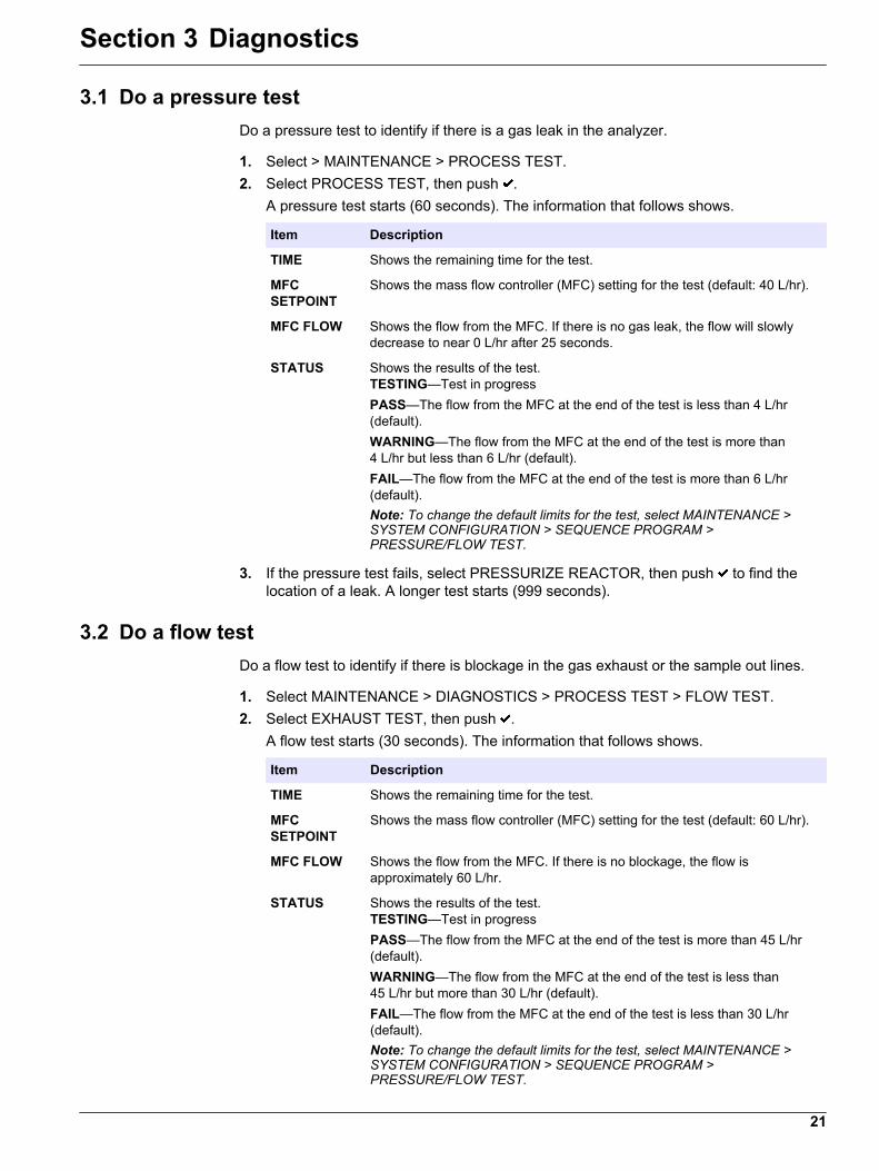
3.1 Do a pressure testDo a pressure test to identify if there is a gas leak in the analyzer.
1. Select > MAINTENANCE > PROCESS TEST.2. Select PROCESS TEST, then push .
A pressure test starts (60 seconds). The information that follows shows.
Item Description
TIME Shows the remaining time for the test.
MFCSETPOINT
Shows the mass flow controller (MFC) setting for the test (default: 40 L/hr).
MFC FLOW Shows the flow from the MFC. If there is no gas leak, the flow will slowlydecrease to near 0 L/hr after 25 seconds.
STATUS Shows the results of the test.TESTING—Test in progressPASS—The flow from the MFC at the end of the test is less than 4 L/hr(default).WARNING—The flow from the MFC at the end of the test is more than4 L/hr but less than 6 L/hr (default).FAIL—The flow from the MFC at the end of the test is more than 6 L/hr(default).Note: To change the default limits for the test, select MAINTENANCE >SYSTEM CONFIGURATION > SEQUENCE PROGRAM >PRESSURE/FLOW TEST.
3. If the pressure test fails, select PRESSURIZE REACTOR, then push to find thelocation of a leak. A longer test starts (999 seconds).
3.2 Do a flow testDo a flow test to identify if there is blockage in the gas exhaust or the sample out lines.
1. Select MAINTENANCE > DIAGNOSTICS > PROCESS TEST > FLOW TEST.2. Select EXHAUST TEST, then push .
A flow test starts (30 seconds). The information that follows shows.
Item Description
TIME Shows the remaining time for the test.
MFCSETPOINT
Shows the mass flow controller (MFC) setting for the test (default: 60 L/hr).
MFC FLOW Shows the flow from the MFC. If there is no blockage, the flow isapproximately 60 L/hr.
STATUS Shows the results of the test.TESTING—Test in progressPASS—The flow from the MFC at the end of the test is more than 45 L/hr(default).WARNING—The flow from the MFC at the end of the test is less than45 L/hr but more than 30 L/hr (default).FAIL—The flow from the MFC at the end of the test is less than 30 L/hr(default).Note: To change the default limits for the test, select MAINTENANCE >SYSTEM CONFIGURATION > SEQUENCE PROGRAM >PRESSURE/FLOW TEST.
21

3. If the exhaust test fails, select EXHAUST FLOW, then push to find the location ofthe blockage (e.g., at the exhaust valve). A longer test starts (999 seconds).
4. Select SAMPLE OUT TEST, then push .A sample out test is started. The test identifies if there is a blockage in the sample outlines.
5. If the sample out test fails, select SAMPLE OUT FLOW, then push to find thelocation of the blockage (e.g., at the sample out valve). A longer test starts(999 seconds).
3.3 Do an ozone testDo an ozone test to identify if the operation of the ozone generator is correct.
1. Install the tester. Refer to information sheet T021. Procedure to check the ozone levelin BioTector with Mixer Reactor.
2. Select MAINTENANCE > DIAGNOSTICS > PROCESS TEST > OZONE TEST.3. Select START TEST.
The analyzer does a pressure test. Then the ozone generator is set to on.4. When the O-ring in the tester breaks, select STOP TEST.
The analyzer removes all of the ozone from the ozone tester (30 seconds). The testresults show on the display.
Item Description
TIME Shows the time for the O-ring to break.
STATUS Shows the results of the test.TESTING—Test in progressPASS—The time to break the O-ring was less than 18 seconds (default).LOW OZONE—The time to break the O-ring was more than 18 seconds but lessthan 60 seconds (default).FAIL—The time to break the O-ring was more than 60 seconds.Note: To change the default limits for the test, select MAINTENANCE > SYSTEMCONFIGURATION > FAULT SETUP > OZONE TEST TIME.
3.4 Do a sample pump testDo a sample pump test to identify the correct forward and reverse times for the samplepump for each sample stream.
1. Select MAINTENANCE > DIAGNOSTICS > PROCESS TEST > SAMPLE PUMPTEST.
2. Select an option.
Option Description
VALVE Sets the SAMPLE or MANUAL fitting used for the test. For example, toselect the SAMPLE 1 fitting, select STREAM VALVE 1.
PUMPFORWARDTEST
Starts the sample pump for the selected stream in the forward direction.
1. Push to stop the timer when the sample is through the sample(ARS) valve and the sample drips into the drain pipe on the side of theanalyzer.
2. Record the time on the display. The time is the correct forward time forthe sample pump (e.g., Sample Pump 1).
Diagnostics
22

Option Description
PUMPREVERSETEST
Starts the sample pump for the selected stream in the reverse direction.
1. Push to stop the timer when the sample lines are empty.2. Record the time on the display. The time is the correct reverse time for
the sample pump.
SAMPLEPUMP
Goes to the MAINTENANCE > COMMISSIONING > SAMPLE PUMP menuto set the forward and reverse times for the sample pumps.
3.5 Do a pH test
C A U T I O N
Chemical exposure hazard. Obey laboratory safety procedures and wear all of thepersonal protective equipment appropriate to the chemicals that are handled. Refer tothe current safety data sheets (MSDS/SDS) for safety protocols.
C A U T I O N
Chemical exposure hazard. Dispose of chemicals and wastes in accordance with local,regional and national regulations.
Do a pH test to identify if the pH of the solution in the reactor is correct at the differentsteps of a reaction.Items to collect:
• pH paper• Glass beaker• Personal protective equipment (refer to MSDS/SDS)
1. Put on the personal protective equipment identified in the safety data sheet(MSDS/SDS).
2. Select MAINTENANCE > DIAGNOSTICS > PROCESS TEST > pH TEST.3. Select RANGE,VALVE.4. Set the operation range (1, 2, or 3) and the stream (e.g., STREAM 1) to use for the
test.Refer to the OPERATION > SYSTEM RANGE DATA screen to see the threeoperation ranges. Select the operation range that agrees with normal measurementsfor the sample stream.
5. Select MODE.6. Select the test mode (e.g., TIC+TOC or TC).7. Select START TEST.8. Push again to confirm that the previous reaction completed normally.
The analyzer does the items that follow in sequence:
• A normal startup completes in approximately 210 seconds (ozone purge, reactorpurge, pressure test and flow test).
• Adds the sample and TIC acid to the reactor. Then the program pauses so theTIC pH can be measured by the user.
• Adds the base reagent to the solution in the reactor. Then the program pauses sothe base pH can be measured by the user.
• Adds the TOC acid to the solution in the reactor. Then the program pauses so thepH can be measured by the user.
• The reactor and CO2 analyzer purge phase is completed.
Diagnostics
23

9. When "TEST TIC pH" shows on the display, select an option.
Option Description
TAKE SAMPLE Sets the sample out valve to on for 0.1 seconds.Select TAKE SAMPLE four times to remove old sample from the sampleout line, then collect a sample in the glass beaker. Use a pH paper toidentify the pH of the sample. The expected pH shows on the display.Note: The loss of volume in the reactor when a sample is collected canhave a negative effect on the pH of the samples collected at the next step.For the best accuracy, collect only one sample during a pH test, thencomplete the test. Start the pH test again and collect a sample at adifferent step (e.g., TEST BASE pH).
CONTINUE TONEXT PHASE
The analyzer goes to the next step of the program.
STOP TEST The analyzer goes to the last step of the program, reactor purge.
10. When "TEST BASE pH" shows on the display, select an option. The options are thesame as for the previous step.
11. When "TEST TOC pH" shows on the display, select an option. The options are thesame as for the previous step.
12. When "CONFIRM ALL TUBES RE-CONNECTED" shows, push to confirm.The reactor and CO2 analyzer purge phase is done.
3.6 Do a sample valve testIdentify if the sample ball valve is aligned with the sample valve ports. Adjust thealignment as necessary.
1. Select MAINTENANCE > DIAGNOSTICS > PROCESS TEST > SAMPLE VALVETEST.
2. Select TEST FIRST FAILURE to start the test.The analyzer rotates the sample valve from sensor position 1, 2, then 3."COMPLETE" shows when the test is completed.
• LOOP COUNT—Shows the number of loops the sample ball valve is rotated foreach adjustment point for each sensor position during the test (default: 2).
• CURRENTLY TESTING—Shows the adjustment points (the time delayimplemented by the software) for each sensor during the test. The adjustmentpoints are from 0 to 15 with 1 point increments.
• FIRST FAILURE POINT—Shows the adjustment point at which the analyzerdoes not detect the position of the valve.
3. Select ADJUST SAMPLE VALVE to set the sample valve stop position to align thesample ball valve with the sample valve ports. Follow the instructions on the display.The analyzer shows the position of the valve (e.g., SENS 1) when the adjustmentvalues are entered.If a 17_SMPL VALVE NOT SYNC fault occurs, refer to the information sheets T018.BioTector Sample Valve Not Synchronized Fault Troubleshooting after ValveReplacement and TT002. BioTector Sample Valve Not Sync Fault QuickTroubleshooting.Note: When the sample valve is replaced, refer to the information sheet M046. Sample ValveAdjustment and Sample Tube Positioning Guidelines.
Diagnostics
24

3.7 Do a base wash testDo a base wash test to examine the base wash and tubing wash cycles. The base washand tubing wash cycles clean the sample tubing with the base reagent.
1. Select MAINTENANCE > DIAGNOSTICS > PROCESS TEST > BASE WASH TEST.2. Select an option.
Option Description
VALVE Sets the sample or manual/calibration port used for the base wash and tubingwash cycles.
START TEST Starts the base wash or tubing wash test.
STOP TEST Stops the base wash or tubing wash test.
3.8 Do simulationsDo simulations to identify if a component (e.g., pumps, valves and mass flow controller)operation is correct.Note: Each time a component is activated, the analyzer will stop the operation of other devices asnecessary to prevent damage to the analyzer.
When the back key is pushed to exit the menu, the analyzer does a pumpsynchronization process.
1. Select MAINTENANCE > DIAGNOSTICS > SIMULATE.The status of the analyzer components show.
2. Select an option.When a component is on, an asterisk (*) shows before the component name on thedisplay.Note: Changes made to settings in this menu are not saved.
Option Description
MFC Sets the mass flow controller (MFC) flow (e.g., 40 L/h). Set the flow.Push to start the mass flow controller (MFC). The measured flowshows at the top of the display.Note: If the flow shown is 0.0 L/h, the MFC is off.
OZONEGENERATOR
Sets the ozone generator to on or off.Note: For safety, before the ozone generator is set to on, a pressuretest is done. If a gas leak is found, the ozone generator is not set toon.
ACID PUMP Sets the acid pump to on or off. Sets the number of pulses (½revolution).When the pump is in operation, the actual pulse time (externalbrackets) and the set pulse time (internal brackets) show.
ACID VALVE Sets the acid valve to on or off.
BASE PUMP Sets the base pump to on or off. Sets the number of pulses (½revolution).When the pump is in operation, the actual pulse time (externalbrackets) and the set pulse time (internal brackets) show.
PH ADJUST VALVE Sets the pH adjust valve to on or off.
BASE VALVE Sets the base valve to on or off.
Diagnostics
25

Option Description
SAMPLE VALVE Sets the sample (ARS) valve to the selected position. Options:SEN1 (sample pump to bypass), SEN2 (sample pump to reactor) orSEN3 (acid or base to reactor).
SAMPLE PUMP Sets the sample pump to the selected operation mode. Options: FWD(forward), REV (reverse), P-FWD (pulse control forward) or P-REV(pulse control reverse).If P-FWD or P-REV is selected, set the number of pulses (½revolution of the pump roller).When the pump is in operation, the actual pulse time (externalbrackets) and the set pulse time (internal brackets) show.
INJECTION VALVE Sets the injection valve to on or off.
REACTOR MOTOR Sets the mixer reactor motor to on or off.
SAMPLE OUTVALVE
Sets the sample out valve to on or off.
EXHAUST VALVE Sets the exhaust valve to on or off.
CALIBRATIONVALVE
Sets the zero or span calibration valve to on or off. Options: ZERO,SPAN or OFF.
STREAM VALVE Sets a stream valve to on or off. Select the number of the streamvalve. Only one stream valve can be set to on at one time.Note: The stream valves can be controlled from the programmablerelays or from the stream expansion (auxiliary) board.
MANUAL VALVE Sets a manual valve to on or off. Select the manual valve. Only onemanual valve can be set to on at one time.
COOLER Sets the cooler to on, off or automatic to identify if the cooler relayoperation is correct.
LEAK DETECTOR The LEAK DETECTOR option cannot be selected. The condition ofthe Liquid Leak Detector alarm input shows on the display.
FAN Sets the fan to on, off or automatic to identify if the fan relay operationis correct. The analyzer temperature shows on the display.When FAN is set to AUTO, the analyzer sets the fan to off when theanalyzer temperature is less than 25 °C. The fan operatescontinuously when the analyzer temperature is more than 25 °C.
TEMP SWITCH Sets the temperature switch to on, off or automatic to identify if thetemperature switch operation is correct.When TEMP SWITCH is set to AUTO, the analyzer sets thetemperature switch to on when the analyzer temperature is 20 °C(default) or higher. The temperature switch stays on until the analyzertemperature is less than 20 °C.
SAMPLER FILL Sets the signal to fill the sampler to on or off. The signal stays on untilset to off.
SAMPLER EMPTY Sets the signal to make the sampler empty to on or off. The signalstays on for 5 seconds.
SAMPLER ERROR Sets the signal for a sampler error to on or off. The sampler errorsignal is normally sent from the sampler when there is an error in thesampler.
SAMPLE SENSOR The SAMPLE SENSOR option cannot be selected. The condition ofthe sample sensor shows on the display.
REACTOR PURGE Starts the reactor purge operation.
Diagnostics
26

Option Description
RUN REAGENTSPURGE
Starts the reagent prime operation, which fills the reagent tubing withreagent.
INPUT/OUTPUTSTATUS
Goes to the MAINTENANCE > DIAGNOSTICS > INPUT/OUTPUTSTATUS menu. The INPUT/OUTPUT STATUS menu shows theconditions of the digital inputs, digital outputs, analog inputs andanalog outputs.
3.9 Do a relay or 4–20 mA output testDo a signal simulation to identify if the relay and 4–20 mA output operation is correct.
1. Select MAINTENANCE > DIAGNOSTICS > SIGNAL SIMULATE.2. Select an option.
Option Description
ALARM Sets the ALARM relay to on if configured.
CHANNEL 1 to 6 Sets a 4–20 mA output (e.g., CHANNEL 1 = 4–20 mA signal out,1) to a selected 4–20 mA signal.
CO2 ALARM Sets the CO2 ALARM relay to on if configured.
STM ALARM 1 to 6 Sets a STM ALARM relay to on if configured.
SAMPLE FAULT 1 Sets the SAMPLE FAULT 1 relay to on if configured.
SYNC RELAY Sets the SYNC relay to on if configured.
SAMPLE STATUS Sets the SAMPLE STATUS relay to on if configured.
CAL SIGNAL Sets the CAL SIGNAL relay to on if configured.
MAINT SIGNAL Sets the MAINT SIGNAL relay to on if configured.
REMOTE STANDBY Sets the REMOTE STANDBY relay to on if configured.
STOP Sets the STOP relay to on if configured.
FAULT Sets the FAULT relay to on if configured.
FAULT OR WARN Sets the FAULT OR WARN relay to on if configured.
WARNING Sets the WARNING relay to on if configured.
NOTE Sets the NOTE relay to on if configured.
MAN MODE TRIG Sets the MAN MODE TRIG relay to on if configured.
4-20mA CHNG Sets the 4-20mA CHNG relay to on if configured.
4-20mA CHNG 1 to 6 Sets a 4-20mA CHNG 1–6 relay to on if configured.
4-20mA READ Sets the 4-20mA READ relay to on if configured.
INPUT/OUTPUT STATUS Goes to the MAINTENANCE > DIAGNOSTICS >INPUT/OUTPUT STATUS menu. The INPUT/OUTPUT STATUSmenu shows the conditions of the digital inputs, digital outputs,analog inputs and analog outputs.
3.10 Show the input and output statusShow the signals at the digital inputs, digital outputs, analog inputs and analog outputs asnecessary.
Diagnostics
27

1. Select MAINTENANCE > DIAGNOSTICS > INPUT/OUTPUT STATUS.2. Select an option.
Option Description
DIGITALINPUT
Shows the digital signal at the digital inputs (1 = active, 0 = not active). "DI"followed by two digits identifies the digital inputs. For example, DI09 is DigitalInput 9.The digital input number is followed by the digital signal at the input and thenthe function. "[PROGRAMMABLE]" identifies the configurable digital inputs.Note: DI09 is the enter key. Push and hold down the enter key to change thedigital signal at DI09 to 1.
DIGITALOUTPUT
Shows the digital signal at the digital outputs (1 = active, 0 = not active). "DO"followed by two digits identifies the digital outputs. For example, DO21 is DigitalOutput 21.The digital output number is followed by the digital signal at the output and thenthe function. "[PROGRAMMABLE]" identifies the configurable digital outputs.Note: When the analyzer is set to on, all of the digital outputs are set to 0.
Note: DO21 has a digital signal of 1 when the cooler is on and 0 when thecooler is off. The cooler operates for approximately 3 seconds and then is offfor 7 seconds.
ANALOGINPUT
Shows the ADC converter digital value, input voltage and function of eachanalog input. The analyzer uses a 12-bit ADC, so the range of the digital valueis 0 to 4095. The input voltage range is 0 to 5.00 V.
ANALOGOUTPUT
Shows the DAC converter digital value, output voltage and function of eachanalog output. The analyzer uses a 12-bit DAC, so the range of the digital valueis 0 to 4095. The output voltage range is 0 to 10.00 V.
3.11 Show the oxygen controller statusShow the system air supply, oxygen supply, gas flow, pressure and temperatureparameters.
1. Select MAINTENANCE > DIAGNOSTICS.2. Select O2-CTRL STATUS.
The oxygen concentrator is set to on. The information that follows shows on thedisplay:
• IDENTIFICATION—The identification number for the oxygen controller board.• VERSION—The software version of the oxygen controller board.• MODE—Sets the mode of the oxygen controller board. The modes follow:
MFC: The oxygen controller board operates the mass flow controller.O2: The oxygen controller board operates the oxygen concentrator.MFC AND O2: The oxygen controller board operates the MFC and oxygenconcentrator.
• TEMPERATURE SENSOR—The first value is the temperature of the analyzer atthe oxygen controller board. The second value is the voltage reading from thetemperature sensor.
• AIR PRESS SENSOR—The first value is the air inlet pressure for the oxygenconcentrator. The second value is the voltage reading from the air pressuresensor.
• O2 PRESS SENSOR— The first value is the oxygen inlet pressure for the MFC(normally 400 mbar (±10 mbar) at 20 L/h MFC setpoint. The second value is thevoltage reading from the oxygen pressure sensor.
Diagnostics
28

• VALVE1, 2, 3—The oxygen controller valve outputs for Valves 1, 2 and 3 (1 = on,0 = off). Valve 1 is the air isolation valve. Valve 2 and 3 are reserved.
• ROTARY VALVE—The operation of the rotary valve (FORWARD, REVERSE orSTOP).
• ROTARY VALVE SENSOR—The sensor position of the rotary valve (1 = rotaryvalve is on the sensor, 0 = the valve is not on the sensor).
• MFC SETPOINT—Sets the setpoint for the mass flow controller. Push enter(checkmark icon), select the setpoint, then push enter again. The MFC flowshows at the top of the display. The MFC is off when the flow is 0.0 L/h.
• MFC FLOW—The first value is the MFC flow. The second value is the voltagereading from the MFC. When the analyzer is stopped or in remote standby, theMFC setpoint is 1 L/h.
3.12 Show the Modbus status1. Select MAINTENANCE > DIAGNOSTICS > MODBUS STATUS.2. Select an option.
Option Description
MODE Shows the Modbus operating mode, which is BIOTECTOR.
DEVICE BUS ADDRESS Shows the Modbus address of the instrument.
BUS MESSAGE COUNT Shows the number of Modbus messages that were correctlyreceived and were sent to the Modbus address of theinstrument.Note: When the count is 65,535, the subsequent messagereceived sets the count to 1.
BUS COM ERRORCOUNT
Shows the number of corrupted or not fully received Modbusmessages that the Modbus received.Note: When the count is 65,535, the subsequent messagereceived sets the count to 1.
MANUFACTURE ID Shows the manufacturer ID for the instrument (e.g., 1 for Hach).
DEVICE ID Shows the class or family of the instrument, if entered (default:1234).
SERIAL NUMBER Shows the serial number of the instrument.
LOCATION TAG Shows the location of the instrument.
FIRMWARE REV Shows the firmware revision installed on the instrument.
REGISTERS MAP REV Shows the Modbus register map version used by theinstrument. Refer to the Modbus register maps in the AdvancedConfiguration Manual.
After the menu options, the first 17 bytes of the last received (RX) and transmitted (TX)Modbus message show.
3.13 Modbus troubleshooting1. Make sure that the device bus address is correct. Refer to the Configure the Modbus
settings in the Installation and Operations Manual.2. Make sure that the register address (5-digit code) is correct.3. Select MAINTENANCE > DIAGNOSTICS > MODBUS STATUS > BUS COM ERROR
COUNT. Look at the bus transmission error count.
Diagnostics
29

The bus error count should increase each time the analyzer reads an invalid or notfully received Modbus message.Note: Valid messages that are not addressed to the instrument do not increase the counter.
4. For the Modbus RTU option, make sure that the wire connected to terminal D+ ispositively biased compared to the wire connected to terminal D– when the bus is inan idle condition.
5. Make sure that there is a jumper installed on J15 of the motherboard at the end of thebus to terminate the bus. The motherboard is in the electronic enclosure on the doorbehind the stainless steel cover.
6. For the Modbus TCP option, open the web interface. Refer to Configure the ModbusTCP/IP module in the Installation and Operation Manual. If the web interface does notopen, do the steps that follow:
a. Make sure that the network settings are correct.b. Make sure that the Ethernet cable connectors are fully installed in the Ethernet
ports.c. Make sure that the LED for the Modbus TCP/IP (RJ45) connector is green.
Diagnostics
30
Section 4 Analysis enclosure
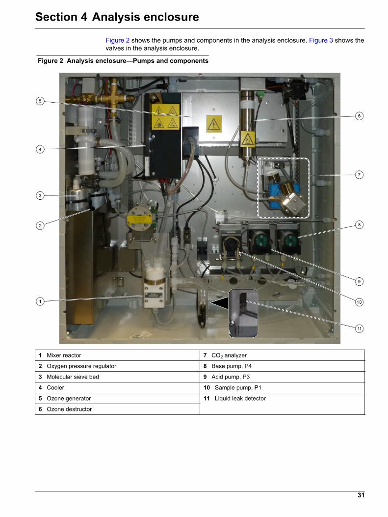
Figure 2 shows the pumps and components in the analysis enclosure. Figure 3 shows thevalves in the analysis enclosure.
Figure 2 Analysis enclosure—Pumps and components
1 Mixer reactor 7 CO2 analyzer
2 Oxygen pressure regulator 8 Base pump, P4
3 Molecular sieve bed 9 Acid pump, P3
4 Cooler 10 Sample pump, P1
5 Ozone generator 11 Liquid leak detector
6 Ozone destructor
31
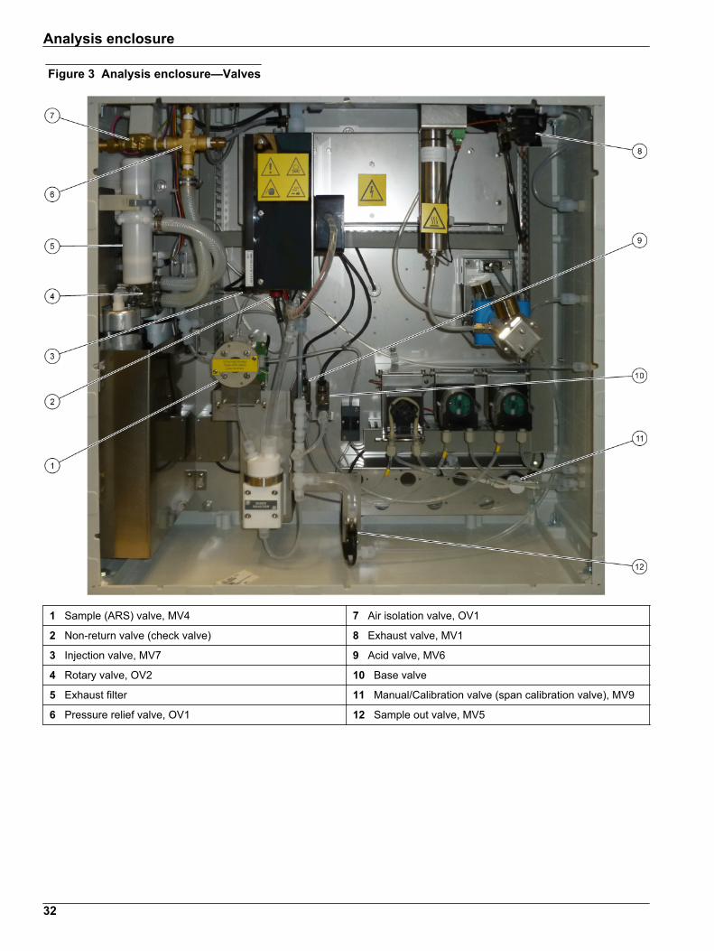
Figure 3 Analysis enclosure—Valves
1 Sample (ARS) valve, MV4 7 Air isolation valve, OV1
2 Non-return valve (check valve) 8 Exhaust valve, MV1
3 Injection valve, MV7 9 Acid valve, MV6
4 Rotary valve, OV2 10 Base valve
5 Exhaust filter 11 Manual/Calibration valve (span calibration valve), MV9
6 Pressure relief valve, OV1 12 Sample out valve, MV5
Analysis enclosure
32

Section 5 Control enclosure components
Figure 4 Control enclosure components
1 Power supply, for main board/motherboard 9 Relay PCB
2 Power supply, for pumps and valves 10 Auxiliary/stream expansion PCB (optional)
3 Mains power PCB (printed circuit board) 11 Mass flow controller
4 Main power switch 12 Oxygen Controller Board
5 Motherboard 13 Ozone PCB
6 LCD screen brightness access hole 14 4-20 mA isolators
7 SD/MMC card slot 15 Fan
8 Signal PCB
33
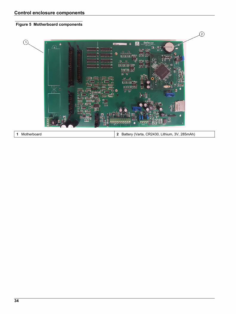
Figure 5 Motherboard components
1 Motherboard 2 Battery (Varta, CR2430, Lithium, 3V, 285mAh)
Control enclosure components
34

Section 6 Replacement parts and accessories
W A R N I N G
Personal injury hazard. Use of non-approved parts may cause personal injury, damageto the instrument or equipment malfunction. The replacement parts in this section areapproved by the manufacturer.
Note: Product and Article numbers may vary for some selling regions. Contact the appropriatedistributor or refer to the company website for contact information.
Consumables
Description Quantity Item no.
Acid reagent, 1.8 N Sulfuric Acid containing 80mg/L Manganese Sulfate Monohydrate 20 L(5.2 gallons) 25255061
Base reagent, 1.2 N Sodium Hydroxide 20 L(5.2 gallons) 2985562
Deionized water 4 L (1 gallon) 27256
TOC standard, 50.0 mg/L 4 L 5847200
TOC standard, 100 mg/L 1 L LCW843
TOC standard, 200 mg/L 1 L LCW845
TOC standard, 250 mg/L 1 L LCW848
TOC standard, 500 mg/L 1 L LCW846
TOC standard, 500 mg/L 4 L 5847300
TOC standard, 1000 mg/L 4 L 5846900
TOC standard, 5000 mg/L 4 L 5847400
Replacement parts
Description Quantity tostock Item no.
6-month maintenance kit, B7000i Dairy TOC analyzer 1 19-KIT-132
Air isolation valve, N/C 0 19-B5C-012
Acid pump or base pump, SR25 0 19-ASF-004
ARM main board, Rev 9, includes:processor and LCD 0 19-PCB-053
CO2 analyzer, Hastelloy, 0–15000 ppm 0 20-CO2-011
Cooler , B4M with glass bead filter 0 19-BAS-018
Exhaust filter/muffler 1 10-DVB-005
Instrument air filter pack, B5C 0 10-SMC-001
Filter pack elements for air supply, B5C 13 12-SMC-001
Isolation amplifier 1 10-KNK-001
Mass flow controller (MFC) 0 12-PCP-001
Mixer reactor motor, B4M, 24 VDC, complete with leak detection 1 19-BAS-015
Mixer reactor, B4M, PTFE, complete with 24 VDC motor 0 19-BAS-016
Mixer reactor, B4M, PTFE 0 19-BAS-017
3 Normally replaced at 24 month intervals.
35

Replacement parts (continued)
Description Quantity tostock Item no.
Ozone destructor heater 0 10-HAW-001
Oxygen concentrator, pressure regulator 0 10-DVB-012
Oxygen concentrator, pressure relief valve 0 10-DVB-024
Oxygen concentrator, rotary valve 1 20-B5C-011
Oxygen concentrator, molecular sieve beds (2) 1 12-DVB-013
Oxygen control board, complete 0 20-PCB-136
Power board, 115 VAC analyzer, B7000 1 19-PCB-160
Power board, 230 VAC analyzer, B7000 1 19-PCB-250
PTFE diaphragm for mixer reactor 1 10-KNF-038
PTFE ferrule and PEEK locking ring set, 1 x 3/16-in. 5 10-EMT-136
PTFE ferrule and PEEK locking ring set, 1 x 1/4-in. 5 10-EMT-114
Sample pump, WMM60, with Norprene chemical tubing 13 19-MAX-010
Tubing, PFA, 3/16-in. OD x 1/8-inch ID, 1 m length 5 m length 10-SCA-002
Tubing, PFA, 1/4-in. OD x 4 mm ID, 1 m length 5 m length 10-SCA-003
Tubing, PFA, 1/4-in. OD x 1/8-in. ID (6.35-mm OD x 3.18-mm ID), 1 m length 5 m length 10-SCA-006
Tubing, PFA, 3/16-in. OD x 1/16-inch ID, 1 m length 1 m length 10-SCA-007
Tubing, EMPP 562, 6.4 mm OD x 3.2 mm ID, 1 m length 2 m length 10-REH-002
Tubing, EMPP, 5.6 mm OD x 2.4 mm ID, 1 m length 1 m length 10-REH-003
Tubing, sample pump, WMM60, Norprene, 1/4-in. OD x 1/8-in. ID (6.4-mm OD x 3.2-mm ID), 2 x 156.5 mm 13 12-CPR-006
Valve, N/C with plug, Type 6606 Burkert 1 19-EMC-001
Valve, N/O with plug, Type 6606 Burkert 1 19-EMC-002
Valve, C/O with plug, Type 6606 Burkert 1 19-EMC-003
Valve, non-return (check valve), 1 psi 1 10-SMR-001
Valve, pinch, B4M, C/O, complete 0 12-BIO-001
Valve, sample, PEEK ARS, 2.5 mm with integrated fittings 13 10-EMT-090
Replacement parts and accessories
36


HACH COMPANY World HeadquartersP.O. Box 389, Loveland, CO 80539-0389 U.S.A.Tel. (970) 669-3050(800) 227-4224 (U.S.A. only)Fax (970) [email protected]
HACH LANGE GMBHWillstätterstraße 11D-40549 Düsseldorf, GermanyTel. +49 (0) 2 11 52 88-320Fax +49 (0) 2 11 52 [email protected]
HACH LANGE Sàrl6, route de Compois1222 VésenazSWITZERLANDTel. +41 22 594 6400Fax +41 22 594 6499
© Hach Company/Hach Lange GmbH, 2020. All rights reserved. Printed in Ireland. *DOC023.52.90645*