maintenance gearbox and online monitoring
TRANSCRIPT
8/13/2019 Maintenance Gearbox and Online Monitoring
http://slidepdf.com/reader/full/maintenance-gearbox-and-online-monitoring 1/8
Michel Wendling is the Manager of theClient Support Department of Flender-Graffenstaden, in Illkirch-Graffenstaden,France. He has more than 30 yearsexperience in the field of high-speed turbogears. His activities today includeinspection on site, studding for revamping,as well as improvement of gearbox designby using return of experiences.
Mr. Wendling has a diploma (Electricityand Mechanical Engineering) from the
High National School of Nancy and received a Dr-Ing. degree fromthe University of Grenoble, in France.
Edwin Becker is the Manager of theCondition-Monitoring Department of Flender Service GmbH, in Herne,Germany. Before joining the Flender
Group in 1996, he worked 10 years for ASUG Getriebwerk, in Dessau, Germany, first in the Design and Research Department, and then in the After Sales and Quality Department.
Dr. Becker received his Dr.rer.nat fromthe University of Halle/Saale, in Germany.
ABSTRACT
As a result of cost reductions, there are fewer and fewer gearspecialists in compressor and turbine companies, as well as in themaintenance groups of users. Therefore, these groups rely on thegear manufacturer’s expertise for gear maintenance.
This paper is based on the authors’ field experience. It uses
examples and case studies of investigation and troubleshooting.The use of vibration analysis for gearboxes having multiplesources of excitation is examined. The paper proposes differentsolutions to increase reliability and availability of gearboxesinstalled on turbo units. An important chapter deals with modernequipment for condition monitoring, which offers a direct Internetlink between site and gearbox diagnostic specialists.
INTRODUCTION
Gearboxes, whether used for turbo units or for low-speedapplications, are unique. Gearboxes are passive units, installedbetween drivers and driven machines, with excitations coming
from two directions through both shafts and couplings. Thegearbox base is fitted on a skid that can be excited by foundationvibrations. Gearbox performance is also influenced by the qualityof the oil, e.g., oil flow, correct input of oil pressure andtemperature, constant oil physical properties, no contamination bywater or metallic particles, sufficient aeration time in oil tank, etc.Sometimes, transient changes in the process conditions caninfluence gearbox behavior, for example, during startup withtorsional torque, or in case of false electrical coupling on thegenerator, compressor surge, entry of water in the compressor, orwhen casing thermal expansion produces misalignment betweenmachines.
For reasons such as these, troubleshooting on gearboxes is oftendifficult. A well-known methodology is to go step-by-step fromquality claim to measurements and research of correlationsbetween parameters, from measurement to diagnostics, and at thevery least, from a correct diagnosis to improvement.
In correlation research between the parameters, some effects of a secondary cause can hide the primary cause. To avoid problems,investigation on gearboxes requires a good knowledge of gear andsleeve bearing operation, as well as skill in the use of modernmeasurement tools. The first step in diagnosis is the analysis of pertinent measurements, inside and outside the gearbox.Sometimes, service companies carry out this first step, but theyoften record information that is not sufficient for correct diagnosisof the problem. Gear manufacturers, with experience in the turbomarket, are not only able to collect the data required for problemdiagnosis, but also have the experience necessary to decide themost effective course of action. The gearbox manufacturer is notonly the supplier of one component, he is a specialist working inpartnership with the OEM, engineering companies, and end-users.
INSTRUMENTATION ON GEARBOXES
Gearbox protection and maintenance are mainly based onvibration measurement (shafts and casing) and on bearingtemperature measurement.
Probes are commonly used for the monitoring of complete turbounits. Typically gearboxes for the petroleum industry aremonitored with many probes, for protection or for maintenance.Information that is available can detect abnormal operations. Withtime, the probability failure increases. Troubles in gearboxprotection and maintenance can be due to a lack of reliability of probes, or trouble in measurement. The power generation industry,on the other hand, uses specification that tends to reduce instru-mentation cost by limiting the number of probes installed on thegearbox. For example, gearboxes between turbines and generatorsare often protected by only thermal probes in sleeve bearings and
95
MAINTENANCE AND ONLINE DIAGNOSTICS
ON GEARBOXES IN THE PETROCHEMICAL INDUSTRY
by
Michel Wendling
Manager, Client Support Department
Flender-Graffenstaden
Illkirch-Graffenstaden, France
and
Edwin Becker
Manager, Condition Monitoring Department
Flender Service GmbH
Herne, Germany
8/13/2019 Maintenance Gearbox and Online Monitoring
http://slidepdf.com/reader/full/maintenance-gearbox-and-online-monitoring 2/8
thrust bearings with one accelerometer on the casing. Investigationin this case cannot be aided by information from multiple sources,and diagnosis will require the use of portable probes or the use of new temporary probes installed on provisional points that weredesigned by the gear manufacturer and used for initial shop testing.
Vibration Measurements
Vibration investigation is probably the best tool to detect theorigin of a gearbox malfunction, but most monitoring systemsdetect overall vibration values on a large frequency band.
Unfortunately, gearboxes containing multiple shafts can generateexcitations at different frequencies. Each shaft has its own criticalspeed. Bearings on each shaft can generate fluid film instabilitiesat different frequencies.
A simple spectrum analysis in low frequency range will indicatethe part each shaft plays in the global vibration level and/or detectsubsynchronous instabilities in bearings. In the high frequencyrange, fast Fourier transform (FFT) analysis of the casing vibrationcan also identify the difference between, for example, meshfrequency, a natural frequency, or a cavitation frequency generatedby a mechanical oil pump. Accelerometer information in lowfrequency range can confirm shaft displacement measurement andimprove unit protection reliability for alarm and trip. A rapiddetection of the main vibration components in the FFT spectrumcan be very useful to focus an investigation on the root causes of a
problem.
Temperature Measurements
For sleeve bearing temperature measurements, flexibleresistance temperature detector (RTD) probes are often specified.This type of probe has good precision, but is more fragile than athermocouple. The sensitive end of the RTD probe is brittle andcan be broken by vibrations. This can cause a unit shutdown andinvolve maintenance action for its replacement. To avoidequipment shutdowns due to a broken probe, install two separatedsimplex probes at each temperature measurement point, on theradial bearing or thrust pads, with a voting logic on the monitoringsystem.
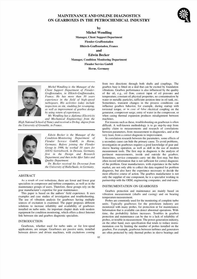
In many cases today, the gearbox is inside a closed packagewithout a crane for ease of disassembly. Special mechanical
designs allow bearing thermal probe replacement without casingdisassembly (Figure 1). From a general point of view, smallincreases in capital cost, similar to this example, couldconsiderably reduce the maintenance costs and productiondowntime during the operating life of turbo units (accessibility tomachines, cranes, etc.).
OPERATING DIAGNOSTICS ON GEARBOXES
The cases below illustrate problems encountered by a gearspecialist while diagnosing vibration levels on site.
Overall Vibration Measurements on
Gearbox Casing Are Not Sufficient for Diagnosis
As explained above, gearbox shaft vibration can be detected onthe casing. But external forces that are transmitted through thefoundation and gearbox skid can also excite the casing. For thesereasons, the casing overall vibration measurement on the gearboxalone will not yield a correct explanation of the origin of aproblem.
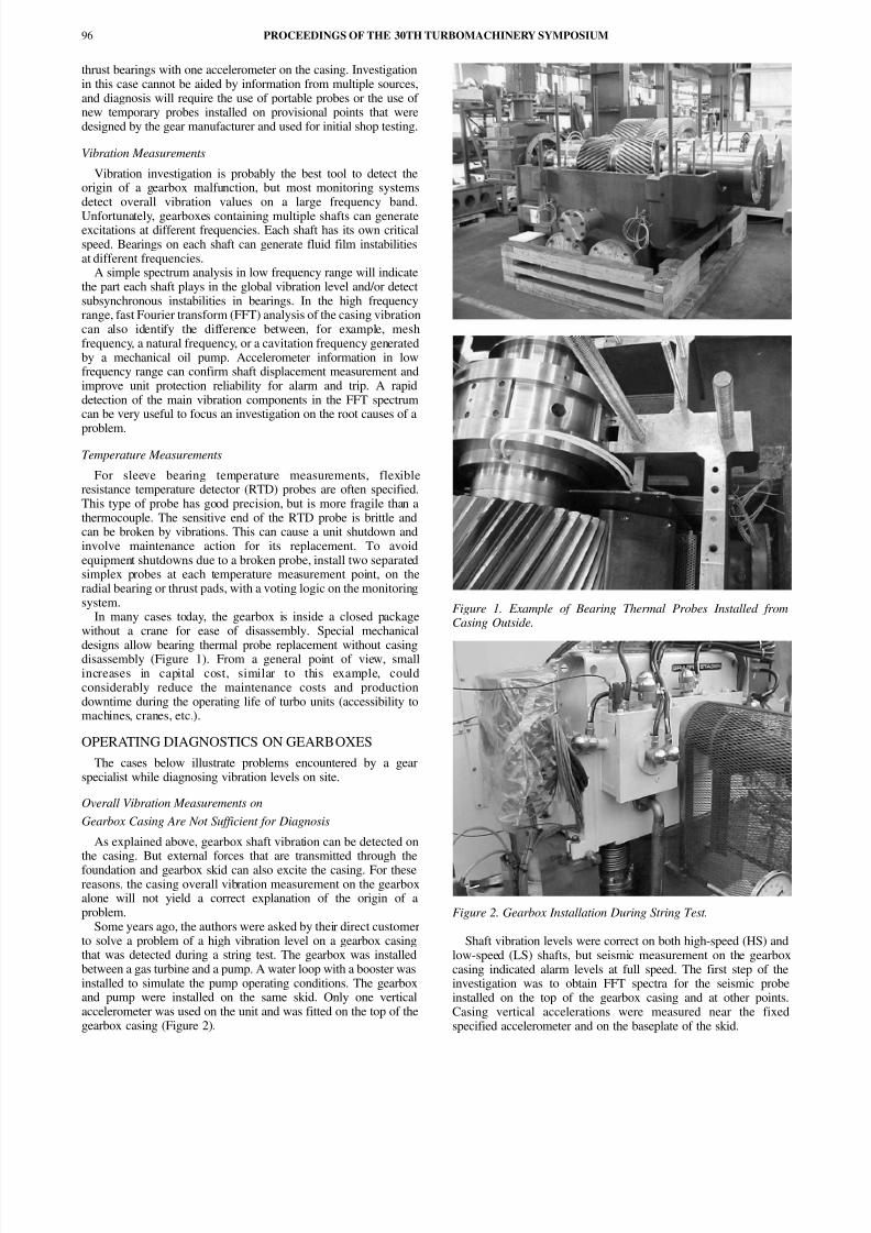
Some years ago, the authors were asked by their direct customerto solve a problem of a high vibration level on a gearbox casingthat was detected during a string test. The gearbox was installedbetween a gas turbine and a pump. A water loop with a booster wasinstalled to simulate the pump operating conditions. The gearboxand pump were installed on the same skid. Only one verticalaccelerometer was used on the unit and was fitted on the top of thegearbox casing (Figure 2).
Figure 1. Example of Bearing Thermal Probes Installed fromCasing Outside.
Figure 2. Gearbox Installation During String Test.
Shaft vibration levels were correct on both high-speed (HS) andlow-speed (LS) shafts, but seismic measurement on the gearboxcasing indicated alarm levels at full speed. The first step of theinvestigation was to obtain FFT spectra for the seismic probeinstalled on the top of the gearbox casing and at other points.Casing vertical accelerations were measured near the fixedspecified accelerometer and on the baseplate of the skid.
PROCEEDINGS OF THE 30TH TURBOMACHINERY SYMPOSIUM96
8/13/2019 Maintenance Gearbox and Online Monitoring
http://slidepdf.com/reader/full/maintenance-gearbox-and-online-monitoring 3/8
MAINTENANCE AND ONLINE DIAGNOSTICS ON GEARBOXES IN THE PETROCHEMICAL INDUSTRY 97
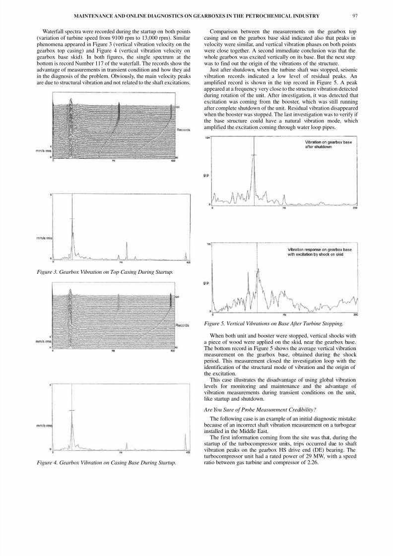
Waterfall spectra were recorded during the startup on both points(variation of turbine speed from 9100 rpm to 13,000 rpm). Similarphenomena appeared in Figure 3 (vertical vibration velocity on thegearbox top casing) and Figure 4 (vertical vibration velocity ongearbox base skid). In both figures, the single spectrum at thebottom is record Number 117 of the waterfall. The records show theadvantage of measurements in transient condition and how they aidin the diagnosis of the problem. Obviously, the main velocity peaksare due to structural vibration and not related to the shaft excitations.
Figure 3. Gearbox Vibration on Top Casing During Startup.
Figure 4. Gearbox Vibration on Casing Base During Startup.
Comparison between the measurements on the gearbox topcasing and on the gearbox base skid indicated also that peaks invelocity were similar, and vertical vibration phases on both pointswere close together. A second immediate conclusion was that thewhole gearbox was excited vertically on its base. But the next stepwas to find out the origin of the vibrations of the structure.
Just after shutdown, when the turbine shaft was stopped, seismicvibration records indicated a low level of residual peaks. Anamplified record is shown in the top record in Figure 5. A peak appeared at a frequency very close to the structure vibration detected
during rotation of the unit. After investigation, it was detected thatexcitation was coming from the booster, which was still runningafter complete shutdown of the unit. Residual vibration disappearedwhen the booster was stopped. The last investigation was to verify if the base structure could have a natural vibration mode, whichamplified the excitation coming through water loop pipes.
Figure 5. Vertical Vibrations on Base After Turbine Stopping.
When both unit and booster were stopped, vertical shocks witha piece of wood were applied on the skid, near the gearbox base.The bottom record in Figure 5 shows the average vertical vibrationmeasurement on the gearbox base, obtained during the shock period. This measurement closed the investigation loop with theidentification of the structural mode of vibration and the origin of the excitation.
This case illustrates the disadvantage of using global vibrationlevels for monitoring and maintenance and the advantage of vibration measurements during transient conditions on the unit,like startup and shutdown.
Are You Sure of Probe Measurement Credibility?
The following case is an example of an initial diagnostic mistakebecause of an incorrect shaft vibration measurement on a turbogearinstalled in the Middle East.
The first information coming from the site was that, during thestartup of the turbocompressor units, trips occurred due to shaftvibration peaks on the gearbox HS drive end (DE) bearing. Theturbocompressor unit had a rated power of 29 MW, with a speedratio between gas turbine and compressor of 2.26.
8/13/2019 Maintenance Gearbox and Online Monitoring
http://slidepdf.com/reader/full/maintenance-gearbox-and-online-monitoring 4/8
A spectrum record was obtained with the local monitoringsystem when the shaft speed approached the trip value (Figure 6).Unfortunately, no waterfall records were supplied, and spectra hada rough resolution. Nevertheless, the spectra indicated that whenthe vibration global values were increasing up to trip, a vibrationpeak at half the shaft frequency was appearing. The first diagnosiswas to suspect an instability on the gearbox HS DE side bearing.
Figure 6. Shaft Vibration on HS DE Side.
This first hypothesis was very strange and very incredible for afive tilting pad bearing, loaded by the gear reaction forces. For thisreason, the first investigation of the bearing design was discarded,and a new direction was decided using a multichannel FFTvibration analyzer. During this new investigation, data wereobtained during startup and shutdown, using the different gearboxshaft vibration probes.
The first important result for diagnosis was that trips on the HSgearbox (GB) shaft did not appear when the unit started in coldcondition or after two or three hours of standby. But in case of arestart a short time after trip, HS shaft vibration was higher thantrip level. Bode diagrams confirmed this assumption: the runout atslow roll was correct during shutdown, but was very high during ahot startup. Figure 7 shows two Bode diagrams that were recordedduring a hot startup.
Figure 7. Bode Diagram for HS Shaft Vibrations on NDE and DE Side During Startup.
HS shaft displacement probes are located at the same radialposition, one on the nondrive end (NDE) side (top diagram) andthe other one on the DE side (bottom diagram). We can observethat the runout phases are very similar.
With all these observations, we suspected that the thermal shaftunbalances were responsible for the differences in the peak vibration during startup, but it was unusual that this peak was nota synchronous vibration and occurred at half shaft frequency.
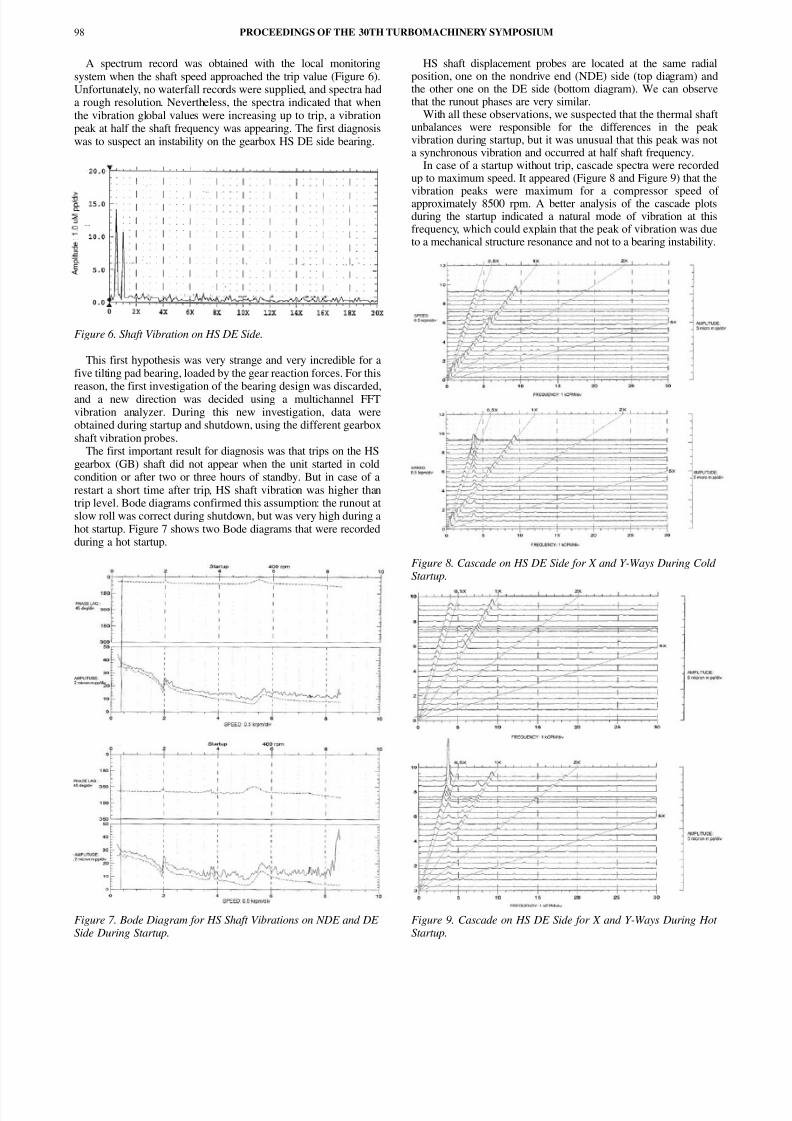
In case of a startup without trip, cascade spectra were recordedup to maximum speed. It appeared (Figure 8 and Figure 9) that the
vibration peaks were maximum for a compressor speed of approximately 8500 rpm. A better analysis of the cascade plotsduring the startup indicated a natural mode of vibration at thisfrequency, which could explain that the peak of vibration was dueto a mechanical structure resonance and not to a bearing instability.
Figure 8. Cascade on HS DE Side for X and Y-Ways During Cold Startup.
Figure 9. Cascade on HS DE Side for X and Y-Ways During Hot Startup.
PROCEEDINGS OF THE 30TH TURBOMACHINERY SYMPOSIUM98
8/13/2019 Maintenance Gearbox and Online Monitoring
http://slidepdf.com/reader/full/maintenance-gearbox-and-online-monitoring 5/8
MAINTENANCE AND ONLINE DIAGNOSTICS ON GEARBOXES IN THE PETROCHEMICAL INDUSTRY 99
We observed two important phenomena on cascade records:
• Resonance appeared only on one probe (Y-way)
• Excitation frequency was not fluid instability but low-speedshaft frequency at 0.44 times the HS shaft frequency (= 1/2.26)
Progress was made with these different measurements, whichled to a coherent explanation. One vibration probe holder wassuspected of having a resonance mode of vibration duringstartup. Variation of resonance response during startup was notdue to the thermal unbalance on the high-speed shaft, but on the
low-speed shaft. Vibrations at low speed frequency weretransmitted to the probe holder through the casing. The intensityof this excitation was a function of the initial thermal unbalanceon the shafts.
Investigations of the drawings confirmed that the probe holdersleeve on the DE Y-way was designed longer than the three othersinstalled on the HS gearbox shaft, and could have a lateral mode of vibration at a frequency around 62 Hz.
The compressor units were on duty for gas reinjection, and itwas very difficult to schedule special tests, modifications, orrepetitive startups. During one short stop of the unit, it was possibleto modify the Y-way probe holder in order to increase its lateralrigidity. The new startup confirmed the origin of the resonance. Notrips occurred, even when the unit restarted immediately after ashutdown.
Troubleshooting took a long time, not only because of the factthat investigation results were difficult to understand, but also forprocess conditions. A gear specialist was onsite for an extendedperiod of time to obtain pertinent measurements. The nextparagraph describes how new electronic devices installed on thegearbox can allow online diagnosis by gear specialists in themanufacturer’s offices.
ONLINE DIAGNOSTICS—
A NEW TOOL IN GEAR SERVICING
Investigations on gearboxes require specialists who are able tounderstand or carry out measurements and who have knowledge ingearbox design, in order to find the correct diagnosis and to decidewhat should be improved. In many cases, it is difficult to have agear specialist onsite for extended periods or when specific
operating conditions arise.For these practical reasons, an Internet technology gear-controller has been developed for remote monitoring of standardindustrial drives and turbodrives via the Internet and onlinediagnosis by gear manufacturing technical teams.
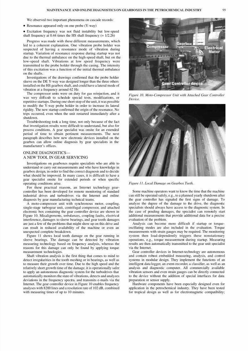
A moto-compressor unit with synchronous motor, coupling,single-stage turbogear unit, centrifugal compressor, and attachedelectronic box containing the gear controller device are shown inFigure 10. Misalignments, unbalances, coupling faults, electricalinterference, damages to sleeve bearings, and gear tooth damagesare just a few of the problems that might show up on this drive andcan result in reduced availability of the machine or even anunexpected complete breakdown.
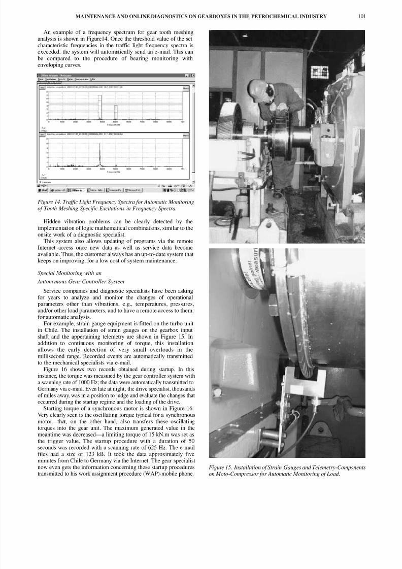
Figure 11 shows local tooth damage on the gear running insleeve bearings. The damage can be detected by vibrationmeasuring technology based on frequency analysis, whereas thereasons for this damage can only be found by applying torquemeasurement technologies.
Shaft vibration analysis is the first thing that comes to mind todetect irregularities in the tooth meshing or in bearings, as well asto measure their growth over time. Due to the high speed and therelatively short growth time of the damage, it is operationally saferto apply an autonomous diagnostic system for the turbodrives thatautomatically monitors the state of vibrations, detects and analyzesdeviations in the frequency spectra, and transmits e-mails via theInternet. The gear controller device in Figure 10 enables frequencyanalyses with 8200 lines and a resolution rate of 102 dB, combinedwith measuring times of up to 10 minutes.
Figure 10. Moto-Compressor Unit with Attached Gear Controller Device.
Figure 11. Local Damage on Gearbox Teeth.
Some machine operators want to know the time that the machinecan still be operated safely, e.g., to a planned yearly shutdown afterthe gear controller has signaled the first signs of damage. Toanalyze the degree of the damage to the drive, the diagnosticspecialists should always have access to the diagnostic system. Inthe case of pending damages, the specialist can remotely startadditional measurements that provide additional data for a preciseevaluation of the problem.
Analysis can become more difficult if startup or torque-oscillating modes are also included in the evaluation. Torquemeasurements with strain gauges may be required. The monitoringsystem then load-dependently triggers these nonstationaryoperations, e.g., torque measurement during startup. Measuringresults are then automatically transmitted to the gear unit specialistvia the Internet.
Gear controller devices in Internet-technology are autonomousand contain robust embedded measuring, analysis, and controlsystems in modular design. They implement the functions of anintelligent data logger, an event-recorder, a classifier, as well as ananalysis and diagnostic computer. All commercially availablevibration sensors and even strain gauges can be directly connectedto the device without the addition of special interfaces for datapreparation or sensor supply.
Hardware components have been especially designed even forapplication in the petrochemical industry. They have been testedfor tropical design as well as for electromagnetic compatibility;

8/13/2019 Maintenance Gearbox and Online Monitoring
http://slidepdf.com/reader/full/maintenance-gearbox-and-online-monitoring 6/8
operating temperatures are between 40°C (104°F) and +70°C(158°F); components withstand shock and vibration loads of up to30 g. Explosion-proof designs are also available and several systemshave been used in the petrochemical industry.
A real-time multitasking operating system in the autonomousgear controller monitors the parallel operation of data logging,triggering, controlling, calculat ion, analysis, storage, andcommunication.
As browsers and e-mail programs are available for all hardwareplatforms, the gear controller can operate totally independently of
the user’s own operating system. When a contact is establishedwith the gear controller device via the Internet HTML, pages fromthe webserver are automatically uploaded into the browser of theuser and can thus be operated there, in order to avoid conflicts of versions and incompatibilities of operating systems.
As transmission control protocol/Internet protocol (TCP/IP) hasalso become a standard with the Intranet, local area network’s(LAN) online diagnostic systems can also be easily upgraded asshown in Figure 12.
Figure 12. Gear Controller Integrated into a LAN/Intranet of Turbo Unit End-User.
TCP/IP communication may be established via standardtelephone modem, ISDN, GSM, RS232, RS485, or even viawireless Ethernet. All transmission modes may be changed at any
time.Remote connection was established between Chile and
Germany, over a distance of more than 12,000 km (~7500 miles)via the Internet by standard analogue modem and standard Internetaccount. Several users may even access the gear controller at thesame time as the real-time operating system allows in carrying outcondition monitoring and online service of these users in parallel.
Basic Functions with an Autonomous Gear Controller System
Based on numerous mobile measurements on different turbounit types, specific compiled software programs for continuouscondition and vibration monitoring can be implemented in the gearcontroller, using different relevant measurement values. Forexample, on a moto-compressor unit in Chile, the inputinformation to the system was:
• Two input ways for load and compressor pressure for recordingof the actual state of the turbo unit and to allow for theinterpretation of nonstationary operating conditions. The loadsignal is also used as a trigger signal for starting of the automaticdiagnostic routines.
• One input way for motor bearing vibrations (measured with anaccelerometer). Data from an accelerometer are generally used toevaluate alignment, operation, and bearing conditions of the motor.
• Two vibration ways on gear unit housing, measured withaccelerometers. Gathered data are being used to evaluate vibrationsrelative to bearings, tooth meshing, and torsional vibrations.
• One bearing temperature way to monitor the axial bearingtemperature. Moreover, this value is used as a trigger value to measuredata only from a gear unit with standard operating temperature.
• One casing vibration way on compressor bearing to enable theearly recognition of changed load cases and to generally monitorcompressor vibrations.
Customers’ maintenance instrumentalists can easily carry outsensor installation. Figure 13 shows two accelerometers attached tothe gear unit housing (left) and the compressor bearing (right). The
customer has to provide a standard telephone line, a stabilized powersupply, the additional values to be measured (preferably as astandardized 4 to 20 mA signal), and an Internet access similar to theones used by home Internet connections. Data and warnings can thusbe transmitted via e-mail and the Internet network. All necessaryfunctions, formulae, and algorithms are included in the program.
Figure 13. Arrangement of Accelerometers on DE Side Housing of Gear Unit and on Compressor DE Side Bearing Housing.
PROCEEDINGS OF THE 30TH TURBOMACHINERY SYMPOSIUM100
8/13/2019 Maintenance Gearbox and Online Monitoring
http://slidepdf.com/reader/full/maintenance-gearbox-and-online-monitoring 7/8
MAINTENANCE AND ONLINE DIAGNOSTICS ON GEARBOXES IN THE PETROCHEMICAL INDUSTRY 101
An example of a frequency spectrum for gear tooth meshinganalysis is shown in Figure14. Once the threshold value of the setcharacteristic frequencies in the traffic light frequency spectra isexceeded, the system will automatically send an e-mail. This canbe compared to the procedure of bearing monitoring withenveloping curves.
Figure 14. Traffic Light Frequency Spectra for Automatic Monitoringof Tooth Meshing Specific Excitations in Frequency Spectra.
Hidden vibration problems can be clearly detected by theimplementation of logic mathematical combinations, similar to theonsite work of a diagnostic specialist.
This system also allows updating of programs via the remoteInternet access once new data as well as service data becomeavailable. Thus, the customer always has an up-to-date system thatkeeps on improving, for a low cost of system maintenance.
Special Monitoring with an
Autonomous Gear Controller System
Service companies and diagnostic specialists have been asking
for years to analyze and monitor the changes of operationalparameters other than vibrations, e.g., temperatures, pressures,and/or other load parameters, and to have a remote access to them,for automatic analysis.
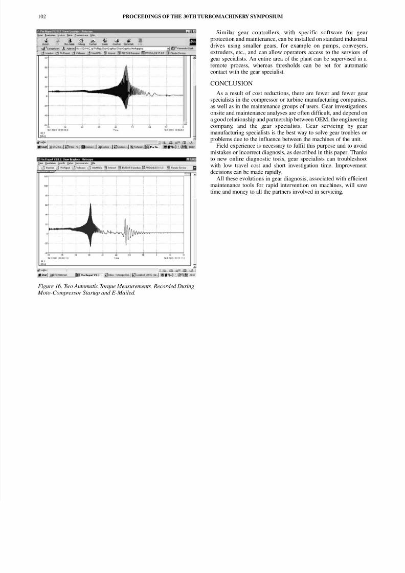
For example, strain gauge equipment is fitted on the turbo unitin Chile. The installation of strain gauges on the gearbox inputshaft and the appertaining telemetry are shown in Figure 15. Inaddition to continuous monitoring of torque, this installationallows the early detection of very small overloads in themillisecond range. Recorded events are automatically transmittedto the mechanical specialists via e-mail.
Figure 16 shows two records obtained during startup. In thisinstance, the torque was measured by the gear controller system witha scanning rate of 1000 Hz; the data were automatically transmitted toGermany via e-mail. Even late at night, the drive specialist, thousandsof miles away, was in a position to judge and evaluate the changes thatoccurred during the startup regime and the loading of the drive.
Starting torque of a synchronous motor is shown in Figure 16.Very clearly seen is the oscillating torque typical for a synchronousmotor—that, on the other hand, also transfers these oscillatingtorques into the gear unit. The maximum generated value in themeantime was decreased—a limiting torque of 15 kN.m was set asthe trigger value. The startup procedure with a duration of 50seconds was recorded with a scanning rate of 625 Hz. The e-mailfiles had a size of 123 kB. It took the data approximately fiveminutes from Chile to Germany via the Internet. The gear specialistnow even gets the information concerning these startup procedurestransmitted to his work assignment procedure (WAP)-mobile phone.
Figure 15. Installation of Strain Gauges and Telemetry-Componentson Moto-Compressor for Automatic Monitoring of Load.
8/13/2019 Maintenance Gearbox and Online Monitoring
http://slidepdf.com/reader/full/maintenance-gearbox-and-online-monitoring 8/8
Figure 16. Two Automatic Torque Measurements, Recorded During Moto-Compressor Startup and E-Mailed.
Similar gear controllers, with specific software for gearprotection and maintenance, can be installed on standard industrialdrives using smaller gears, for example on pumps, conveyers,extruders, etc., and can allow operators access to the services of gear specialists. An entire area of the plant can be supervised in aremote process, whereas thresholds can be set for automaticcontact with the gear specialist.
CONCLUSION
As a result of cost reductions, there are fewer and fewer gear
specialists in the compressor or turbine manufacturing companies,as well as in the maintenance groups of users. Gear investigationsonsite and maintenance analyses are often difficult, and depend ona good relationship and partnership between OEM, the engineeringcompany, and the gear specialists. Gear servicing by gearmanufacturing specialists is the best way to solve gear troubles orproblems due to the influence between the machines of the unit.
Field experience is necessary to fulfil this purpose and to avoidmistakes or incorrect diagnosis, as described in this paper. Thanksto new online diagnostic tools, gear specialists can troubleshootwith low travel cost and short investigation time. Improvementdecisions can be made rapidly.
All these evolutions in gear diagnosis, associated with efficientmaintenance tools for rapid intervention on machines, will savetime and money to all the partners involved in servicing.
PROCEEDINGS OF THE 30TH TURBOMACHINERY SYMPOSIUM102