maintenance manual for the swivel joint and maintenance of the swivel joint 05 3. spare parts ......
TRANSCRIPT

• MAINTENANCE MANUAL FOR THE SWIVEL JOINT
D

TABLE OF CONTENTS
1. INTRODUCTION 04
2. SWIVEL JOINT MAINTENANCE 2.1. Tools required 04 2.2. Disassembling the Swivel joint 04 2.3. Assembly and maintenance of the Swivel Joint 05
3. SPARE PARTS 09
4. CONCLUSION 09
D
4
1. INTRODUCTION
REDLANDS’ swivel joints are used in countless industries. Ranging from truck/rail car loading terminals, hose reels, fl oating suctions, fl oating tank drains, and even rigid or curved pipes, in order to prevent crushing or twisting of heavy or clumsy hoses. They are also used to load or unload chemicals, petrochemicals, hazardous liquids, petroleum-based liquids, dry goods (cereals, cement, etc.) under pressure or vacuum, with no diffi culty at joints.
2. SWIVEL JOINT MAINTENANCE
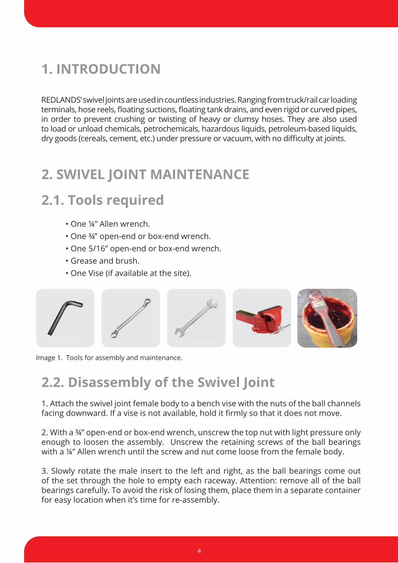
2.1. Tools required • One ¼” Allen wrench. • One ¾” open-end or box-end wrench. • One 5/16” open-end or box-end wrench. • Grease and brush. • One Vise (if available at the site).
Image 1. Tools for assembly and maintenance.
2.2. Disassembly of the Swivel Joint 1. Attach the swivel joint female body to a bench vise with the nuts of the ball channels facing downward. If a vise is not available, hold it fi rmly so that it does not move.
2. With a ¾” open-end or box-end wrench, unscrew the top nut with light pressure only enough to loosen the assembly. Unscrew the retaining screws of the ball bearings with a ¼” Allen wrench until the screw and nut come loose from the female body.
3. Slowly rotate the male insert to the left and right, as the ball bearings come out of the set through the hole to empty each raceway. Attention: remove all of the ball bearings carefully. To avoid the risk of losing them, place them in a separate container for easy location when it’s time for re-assembly.

www.redlands.com.br
5
4. Remove the male insert from inside the female body and keep the dust guard attached to the channel, so that it is completely removed from within the chamber.
5. Remove the o-ring located on the inner housing of the female body. Separate all the components necessary for re-assembly of the swivel joint.
2.3. Assembly and maintenance of the Swivel Joint1. Clean the male insert and all the inner housing of the female body , removing the used grease. Flip the female body over with the ball bearing holes facing upward and re-secure it to a vise or tightly hold the swivel joint so it does not move.
Image 1. Clean the inside of the female body housing.
Image 2. Secure the female body to a vise.
2. With a brush, apply new grease around the inner housing of the female body.
Image 3. Apply the grease with a brush. Image 4. Line the entire housing with grease.

6
3. Before inserting the o-ring into the female body, stretch it so that fi ts perfectly onto its seat. The O-ring is very important to seal the swivel joint, because if there are any gaps or it is not seated properly, there may be a risk of leakage.
Image 5. Place the ring into the female body.
Image 6. The o-ring should be adjusted in the female body.
4. If the same ball bearings must be re-used, clean them carefully. We suggest replacing them with new ones. Clean the dust guard, and place it around the appropriate channel of the male insert. See photo below.
Image 7. Clean the dust guard and male insert .
Image 8. Place the dust guard firmly around the male insert.

www.redlands.com.br
7
5. Insert the male insert into the female body and keep the dust guard tightened in the male insert channel so that it completely enters the chamber. Use light pressure with your hands to force the male insert into the female body. Turn the male insert twice clockwise to assure that it is properly inserted into the female body.
Image 9. Push the male insert forward. Image 10. Turn the male insert clockwise.
6. Before placing the ball bearings into the channel, count them all before inserting them one by one, because none of them can be missing so as not to cause any risk of the swivel joint straddling or locking up. Each channel must contain the right number of ball bearings (see number of ball bearings per joint type, in item 3. SPARE PARTS).
The ball bearing channels of the male insert must be aligned to the female body for easier insertion. Slowly turn the male insert the clockwise and counterclockwise, as the ball bearings are being inserted through the hole.
Image 11. Insert the ball bearings into the channel.
Image 12. Turn clockwise and counterclockwise.

8
7. Place the two screws and the ball bearing retainer with a ¼” Allen wrench holes into the ball bearing holes and screw in clockwise until the screw reach their fitting. Then relieve the screws by loosening them a half-turn and lightly thread the hex nuts with an open-end or box-end wrench to lock the screw in place.
Image 13. Rotate the ball bearing retaining screws clockwise.
Image 14. Turn the nuts onto the bolts to lock them in place.
Note: Don’t forget to turn the screws back a half-turn to relieve them before placing the nuts. Otherwise the ball bearing will get stuck and the swivel joint will lock up.
8. Place the grease fitting with a 5/16” open-end or box-end wrench; this is important for lubricating the swivel joint.
Image 15. Place the grease fitting in the hole.
Foto16. Straight grease fitting.
NOTE: For swivel joint models 3640-FE-40 and 3640-FE-30, the ball bearing retaining screws are secured with 1/4” Allen screws that replace the nuts. (Use 1/8” Allen wrench)Additionally, the grease fitting is installed in one of the retaining screws.

www.redlands.com.br
9
4.CONCLUSION
DESCRIPTION 1 2/1" 2" 3" 4" 6" 8"
Viton O-Ring A0018-0715 A0018-0714 A0018-0713 A0018-0717 A0018-0729 A0018-0737
Buna O-Ring – N A0018-0615 A0018-0614 A0018-0613 A0018-0617 A0018-0629 A0018-0637
Teflon O-Ring A0018-0815TE A0018-0820TE A0018-0830TE A0018-2317 - -
Dust Guard A0019-1003 A0019-1003 A0319-1003 A0319-1003 A0018-0730 A0018-0729
DESCRIPTION
1 2/1" 2" 3" 4" 6" 8"
CODE
Qty ball bearing
s CODE
Qty ball bearing
s CODE CODE
CODE
CODE Qty ball
bearingsQty ball bearings
Qty ball bearings
Qty ball bearings
Stainless steel ball bearing
A6020-4101 56 A0020-
4101 48 A0020-4101 66 A0020-
4101 84 A0020-4105 76 A5120-
4103 116
Chrome steel ball bearing
A6020-4001 56 A0020-
4001 48 A0020-4001 66 A0020-
4001 84 A0020-4006 76 A0020-
4003 116
Note: Number of ball bearings per rotation plane, i.e., two raceways.
3. Spare parts:
Redlands has been ISO 9001 certified since September 2002. This certification represents the service commitment we make to all our customers and employees, and establishes our leading position in this market segment.
Thank you for purchasing Redlands equipment.
For any clarifications or further information, please contact our engineering and technical assistance.

10
Rua Anhanguera, 897 - Jd. Piratininga - Osasco - SP - Cep: 06230-110 – BrazilOffice and Factory: Tel/Fax: +55 11 3602.7300
www.redlands.com.br
LIQUID HANDLING TECHNOLOGY