maintenance needs to be considered -...
TRANSCRIPT
9/24/2013
1
TRANSFORMER
INSTALLATION AND
MAINTENANCE
IEEE Training, Houston, Texas ,
Oct.8-9, 2013
Overview
• Review of Basic Accessories
• Installation of transformer
• Transformer Maintenance

9/24/2013
2
ACCESSORIES
Commonly supplied accessories are:
1. Bushings (e.g. PCORE-Lapp, ABB, HSP).
2. Winding Temperature Indicator.
3. Oil Temperature Indicator.
4. Oil Level Indicator.
5. Gas detector relay (e.g. ABB Model 11 or Buchholz).
6. Silica gel breather.
7. Fans.
8. Pumps.
9. Pressure Relief Device.
10. On-line monitors (ETM, DGA, PD, etc.).
In the next few slides photos of the above accessories and
construction details of some accessories are shown.
PCORE Lapp POC (paper-oil-capacitor) bushing
http://www.hubbellpowersystems.com/bushings/pcore/poc-115kv-500kv/
1.Gaskets - Cork-nitrile rubber gaskets are designed to provide oil-tight seals
2. High Compression Coil Springs -provide uniform, active compressive loading on
gaskets.
3. Clear-View Oil Reservoir (Medium and High Voltage Bushings)
4. Magnetic Oil Gauge (Extra High Voltage Bushings)
5. Porcelain Housing - to provide the required leakage and strike distance and has
ground surfaces on top and bottom ends for oil-tight gasket seals.
6. Name Plate Data - identifies the bushing by catalog number, serial number and year
of manufacture with electrical ratings and factory measurement data.
7. Power Factor Test Tap (Medium Voltage Bushings) - 25 kV through 69 kV . The test
tap is connected to the ground layer of the capacitor core.
8. Voltage Tap or Capacitance Tap (High and Extra High Voltage Bushings) - Bushings
rated at 115 kV and above have a permanent internal ground. In addition, an insulated
tap is connected to a floating capacitor layer. This tap, designated a capacitance tap or a
voltage tap, is grounded except when used as a voltage source with a potential device.
9. Mounting Flange, Ground Sleeve Assembly
10. Paper-Foil Capacitor Core - Conductive layers of aluminium foil with high dielectric
paper
11. Lower Porcelain Assembly
12. Bottom Cap Assembly - A confined cork-nitrile rubber gasket provides a leak-proof
seal between the porcelain and the cap. For bushings rated 115 kV through 161 kV, the
bottom cap is adaptable for use in draw-lead and bottom-connected applications.
13. Dried, Degassed Oil
9/24/2013
3
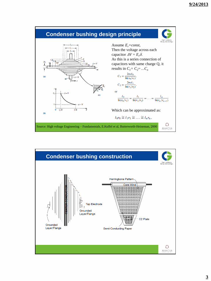
Condenser bushing design principle
Assume Er=const,
Then the voltage across each
capacitor DV = Erd.
As this is a series connection of
capacitors with same charge Q, it
results in C1= C2=…Cn
Which can be approximated as:
Source: High voltage Engineering – Fundamentals, E.Kuffel et al, Butterworth-Heineman, 2000
Condenser bushing construction
9/24/2013
4
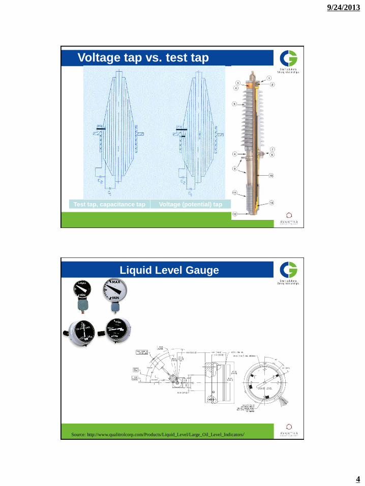
Voltage tap vs. test tap
Test tap, capacitance tap Voltage (potential) tap
Liquid Level Gauge
Source: http://www.qualitrolcorp.com/Products/Liquid_Level/Large_Oil_Level_Indicators/
9/24/2013
5
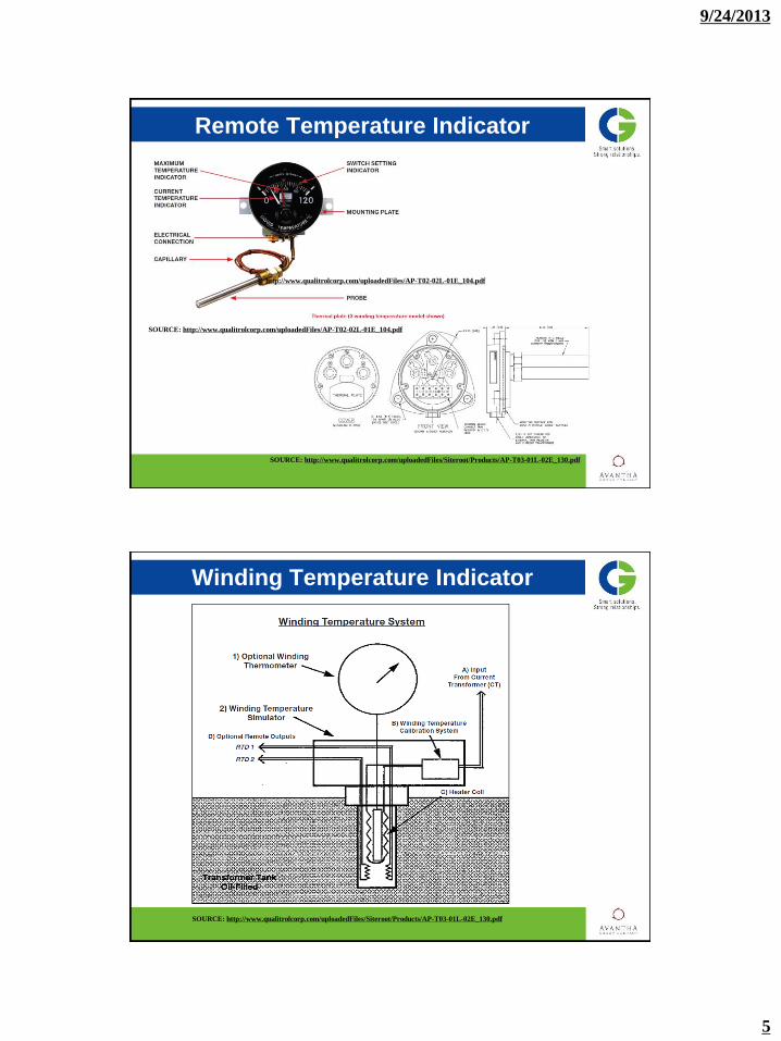
Remote Temperature Indicator
http://www.qualitrolcorp.com/uploadedFiles/AP-T02-02L-01E_104.pdf
SOURCE: http://www.qualitrolcorp.com/uploadedFiles/AP-T02-02L-01E_104.pdf
SOURCE: http://www.qualitrolcorp.com/uploadedFiles/Siteroot/Products/AP-T03-01L-02E_130.pdf
SOURCE: http://www.qualitrolcorp.com/uploadedFiles/Siteroot/Products/AP-T03-01L-02E_130.pdf
Winding Temperature Indicator

9/24/2013
6
SIMULATED HOT SPOT SCHEMATIC
Gas detector relay
The gas detector relay (GDR) is a protective device that gives an early indication of faults occurring
in oil-filled conservator type power transformers:
1. Gas accumulation: Faults of an incipient or minor nature resulting in a slow evolution of gas. This
gas may be generated by local heating, defective insulating structures, improper joints, loose contacts,
grounds, shorted turns, burning of core steel, or from air in the transformer.
2. Rapid pressure: Faults of a major nature that generates a sudden pressure wave. Major faults are
usually caused by breakdown between energized parts, followed by short circuit.
9/24/2013
7
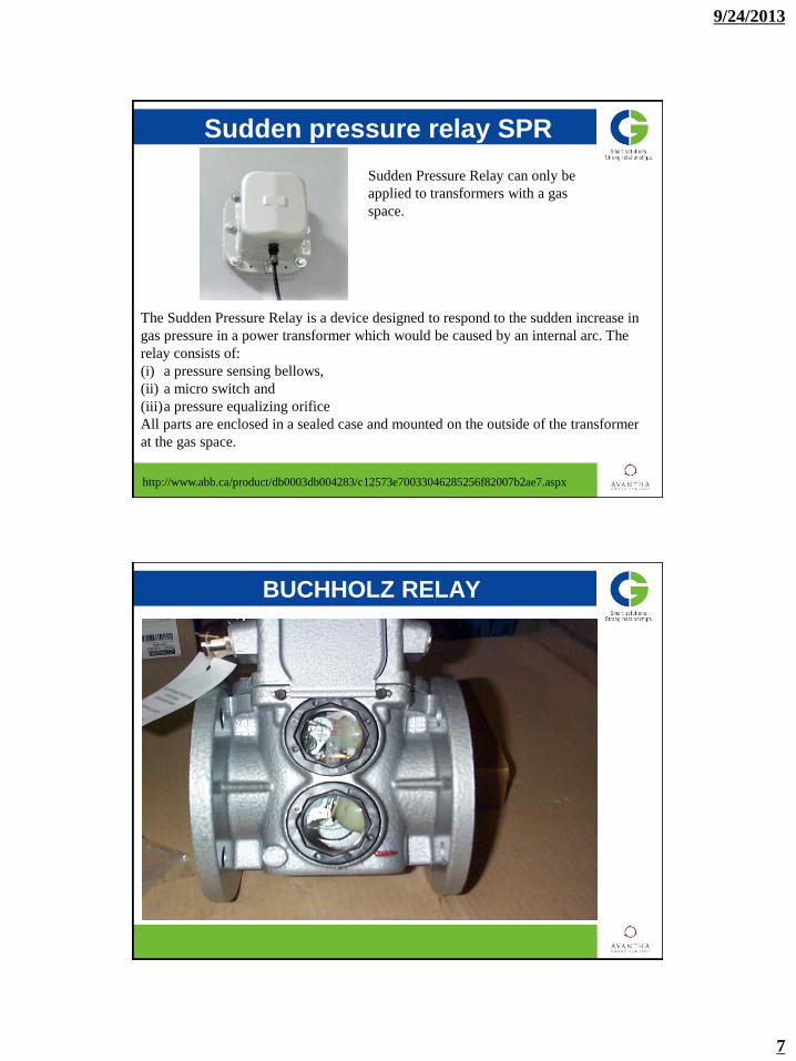
Sudden pressure relay SPR
The Sudden Pressure Relay is a device designed to respond to the sudden increase in
gas pressure in a power transformer which would be caused by an internal arc. The
relay consists of:
(i) a pressure sensing bellows,
(ii) a micro switch and
(iii)a pressure equalizing orifice
All parts are enclosed in a sealed case and mounted on the outside of the transformer
at the gas space.
http://www.abb.ca/product/db0003db004283/c12573e70033046285256f82007b2ae7.aspx
Sudden Pressure Relay can only be
applied to transformers with a gas
space.
BUCHHOLZ RELAY

9/24/2013
8
Operation of Buchholtz relay
Rapid liquid flow
Gas accumulation
Insulating liquid loss
Fault: An internal fault generates a
pressure wave moving toward the
conservator.
Relay response: The liquid flow
reaches a damper located in the
liquid flow. If the flow rate exceeds
the operating threshold of the
damper, it moves in flow direction.
Due to this movement a switch
contact is actuated so that the
transformer is de-energized.
Fault: Free gas is present in the
insulating liquid.
Relay response: The gas in the
liquid moves up, accumulates in
the Buchholz relay and displaces
the insulating liquid level. The
moving float actuates a switch
contact with an alarm signal. The
lower float is not affected as from a
certain gas volume the gas flows
through a piping to the conservator
Fault: Insulating liquid loss
Relay response: As the liquid
level falls the top float moves
downward. An alarm is tripped. If
the liquid loss continues, the lower
float moves downward. The moving
float actuates a switch contact so
that the transformer is de-
energized.
Mounting of Buchholtz relay
9/24/2013
9
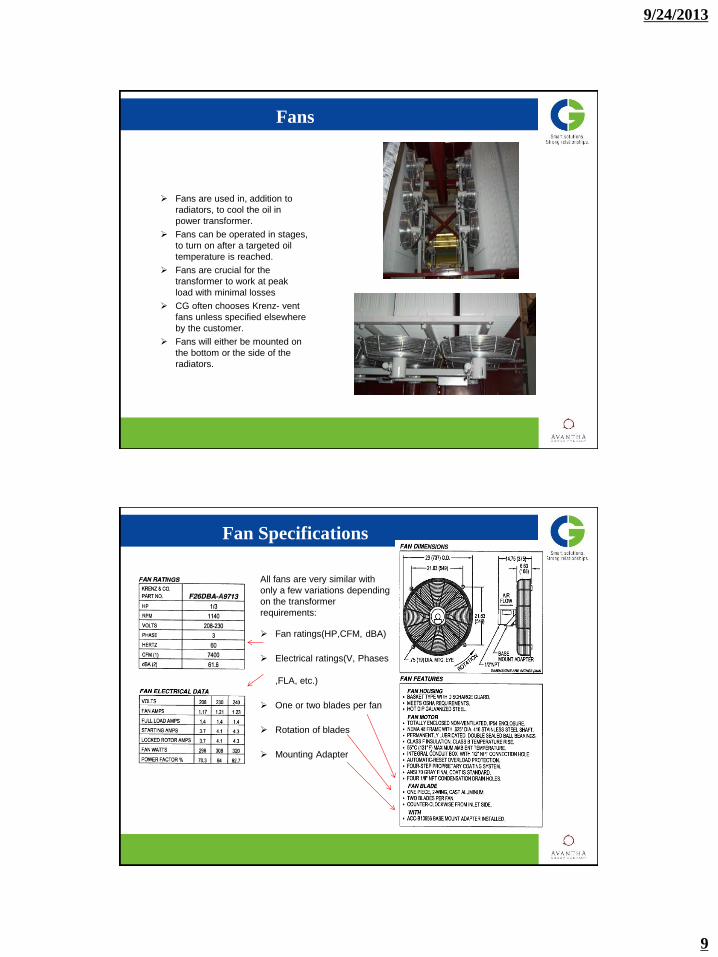
Fans are used in, addition to
radiators, to cool the oil in
power transformer.
Fans can be operated in stages,
to turn on after a targeted oil
temperature is reached.
Fans are crucial for the
transformer to work at peak
load with minimal losses
CG often chooses Krenz- vent
fans unless specified elsewhere
by the customer.
Fans will either be mounted on
the bottom or the side of the
radiators.
Fans
Fan Specifications
All fans are very similar with
only a few variations depending
on the transformer
requirements:
Fan ratings(HP,CFM, dBA)
Electrical ratings(V, Phases
,FLA, etc.)
One or two blades per fan
Rotation of blades
Mounting Adapter
9/24/2013
10
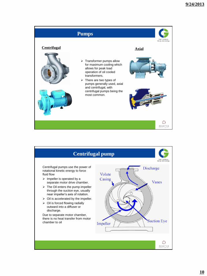
Pumps
Transformer pumps allow
for maximum cooling which
allows for peak load
operation of oil cooled
transformers.
There are two types of
pumps generally used, axial
and centrifugal, with
centrifugal pumps being the
most common.
Centrifugal Axial
Centrifugal pumps use the power of
rotational kinetic energy to force
fluid flow
Impeller is operated by a
separate motor drive chamber.
The Oil enters the pump impeller
through the suction eye, usually
near impeller’s axis of rotation.
Oil is accelerated by the impeller.
Oil is forced flowing radially
outward into a diffuser or
discharge.
Due to separate motor chamber,
there is no heat transfer from motor
chamber to oil
Centrifugal pump

9/24/2013
11
Consists of a motor operated
impeller inside of a pipe.
Oil is pushed by the spinning
blades of the impeller.
The operation allows the pump to
receive and discharge the fluid on
nearly the same axis.
Due to the small mechanical parts
the axial pump is very efficient and
relatively small while also maintain
a high rate of discharge
Axial pump
Pressure relieve device
Source: http://www.qualitrolcorp.com/Products/Pressure_Controls_Gauges_and_Relays/Pressure_Relief_Devices/
Mechanical device for relief of excessive pressure accumulation of large volumes of gas or
fluid in transformer. Gasket system provides quick response time and automatically reseals
after pressure has subsided. Options include local operation indication, contacts (switches)
for operation alarming, and directional shield for hot oil and gas exhaust control.

9/24/2013
12
Silica gel breather/ maintenance-free breather
Source: MR In-sight Magazine, 2009/4; www.reinhausen.com
a) Conventional with change of color from blue to orange, or b) maintenance free
a) b)
Core and clamp ground
9/24/2013
13
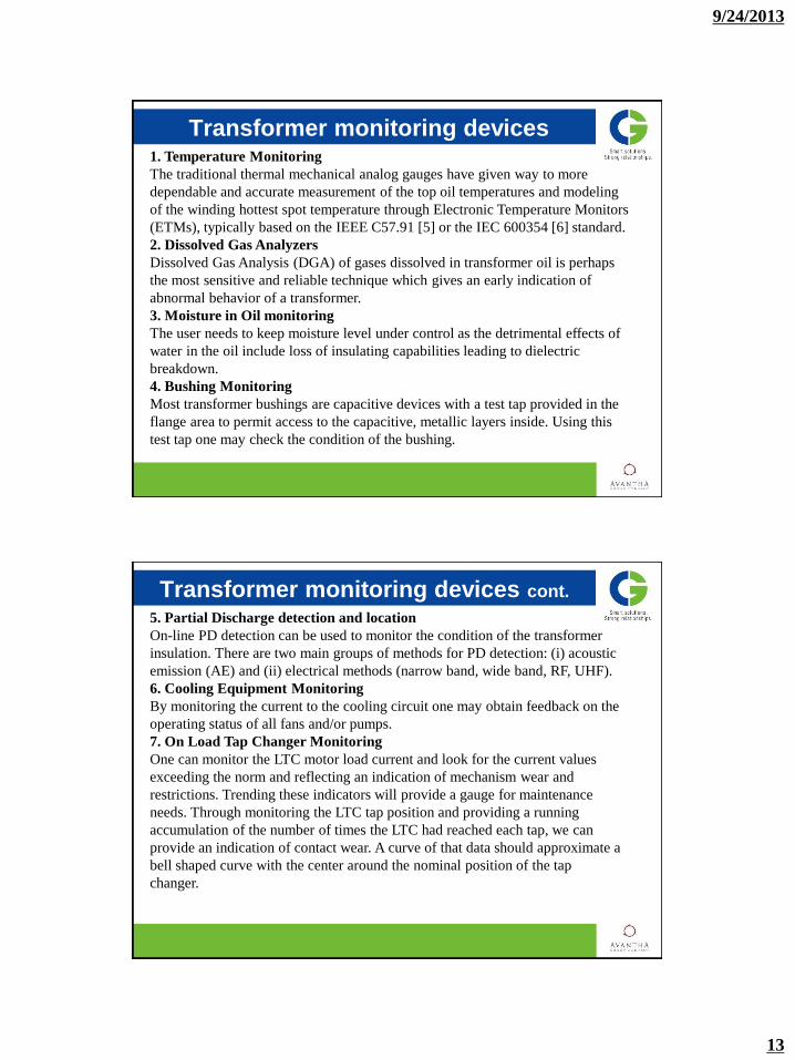
Transformer monitoring devices 1. Temperature Monitoring
The traditional thermal mechanical analog gauges have given way to more
dependable and accurate measurement of the top oil temperatures and modeling
of the winding hottest spot temperature through Electronic Temperature Monitors
(ETMs), typically based on the IEEE C57.91 [5] or the IEC 600354 [6] standard.
2. Dissolved Gas Analyzers
Dissolved Gas Analysis (DGA) of gases dissolved in transformer oil is perhaps
the most sensitive and reliable technique which gives an early indication of
abnormal behavior of a transformer.
3. Moisture in Oil monitoring
The user needs to keep moisture level under control as the detrimental effects of
water in the oil include loss of insulating capabilities leading to dielectric
breakdown.
4. Bushing Monitoring
Most transformer bushings are capacitive devices with a test tap provided in the
flange area to permit access to the capacitive, metallic layers inside. Using this
test tap one may check the condition of the bushing.
Transformer monitoring devices cont.
5. Partial Discharge detection and location
On-line PD detection can be used to monitor the condition of the transformer
insulation. There are two main groups of methods for PD detection: (i) acoustic
emission (AE) and (ii) electrical methods (narrow band, wide band, RF, UHF).
6. Cooling Equipment Monitoring
By monitoring the current to the cooling circuit one may obtain feedback on the
operating status of all fans and/or pumps.
7. On Load Tap Changer Monitoring
One can monitor the LTC motor load current and look for the current values
exceeding the norm and reflecting an indication of mechanism wear and
restrictions. Trending these indicators will provide a gauge for maintenance
needs. Through monitoring the LTC tap position and providing a running
accumulation of the number of times the LTC had reached each tap, we can
provide an indication of contact wear. A curve of that data should approximate a
bell shaped curve with the center around the nominal position of the tap
changer.
9/24/2013
14
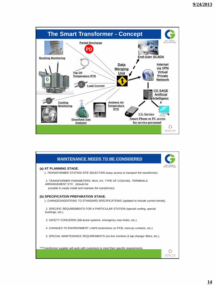
The Smart Transformer - Concept
End-User SCADA
Dissolved Gas
Analyser
Cooling
Monitoring
Partial Discharge
Bushing Monitoring
Internet
via VPN
Virtual
Private
Network
Smart Phone or PC access
for service personnel
CG Service
Data
Merging
Unit
Load Current
Ambient Air
Temperature
RTD
Top Oil
Temperature RTD
CG SAGE
Artificial
Intelligenc
e
MAINTENANCE NEEDS TO BE CONSIDERED
(a) AT PLANNING STAGE.
1. TRANSFORMER STATION SITE SELECTION (easy access to transport the transformer).
2. TRANSFORMER PARAMETERS: MVA, KV, TYPE OF COOLING, TERMINALS
ARRANGEMENT ETC. (should be
possible to easily install and maintain the transformer).
(b) SPECIFICATION PREPARATION STAGE.
1. CHANGES/ADDITIONS TO STANDARD SPECIFICATIONS (updated to include current trends).
2. SPECIFIC REQUIREMENTS FOR A PARTICULAR STATION (special cooling, special
bushings, etc.).
3. SAFETY CONCERNS (fall arrest systems, emergency man-holes, etc.).
4. CHANGES TO ENVIRONMENT LAWS (restrictions on PCB, mercury contacts, etc.).
5. SPECIAL MAINTENANCE REQUIREMENTS (on-line monitors & tap-changer filters, etc.).
***Transformer supplier will work with customers to meet their specific requirements.

9/24/2013
15
MAINTENANCE NEEDS TO BE CONSIDERED (continued)
(c) TENDER EVALUATION STAGE.
1. REQUIREMENT OF SPECIAL TOOLS/PRECAUTIONS FOR EASY INSTALLATION &
MAINTENENCE.
2. BUSHINGS TYPE/MAKE (availability of spares).
3. ACCESSORIES TYPE/MAKE (possible to repair/replace easily).
4. PRECAUTIONS IN VACCUM FILLING (refer TM-410.00).
5. OIL TYPE AND OIL QUANTITY (compatibility with user’s standard oil).
6. EXCEPTIONS TO THE PURCHASING SPECIFICATIONS (should not cause problems
to maintenance).
7. SUFFICIENT ROOM INSIDE THE TANK TO INSPECT AND TO MAKE REPAIRS AT
SITE.
8. SPARE PARTS (should be possible to procure coils etc from repair shops at reasonable
cost).
9. SAFETY CONCERNS (to provide emergency man-holes and other safety requirements).
MAINTENANCE NEEDS TO BE CONSIDERED (continued)
(d) DURING MANUFACTURE.
1. ATTEND DESIGN REVIEW MEETINGS.
2. DEVIATIONS FROM STANDARD MANUFACTURING PRACTICES (welding, brazing
etc).
3. SPECIAL WINDINGS, MAGNETIC SHIELDING, ASSEMBLY ETC (should be possible to
dismantle
and reassemble easily).
4. DESIGN OF GASKET JOINTS AND GASKET MATERIALS (should not develop leaks
during operation).
5. DESIGN PARTS FOR EASY SHIPPING, STORAGE AND ASSEMBLY .
6. PAINT FINISH (not to rust in the field).
9/24/2013
16
SHIPPING
1. DISASSEMBLE AND MATCH MARK PARTS SUCH THAT IT TAKES LESS TIME TO ASSEMBLE IN
THE FIELD.
2. PACK THE PARTS SUCH THAT THEY CAN BE UNPACKED AND REACHED EASILY AND
ORDERLY FOR FAST ASSEMBLY IN THE FIELD.
3. SHOULD BE NO SHORTAGE OF SHIPMENT OF PARTS.
4. PARTS SHOULD BE PACKED FOR OUT-DOOR STORAGE.
5. RECORD DRY AIR DUE POINT AND PRESSURE BEFORE LEAVING THE FACTORY. ALSO
CLEARLY MARK THESE VALUES ON SHIPPING DOCUMENTS.
6. MEASURE CORE GROUND AND CLAMP GROUND RESISTANCES ON THE RAIL CAR AND
RECORD THESE VALUES ON SHIPPING DOCUMENTS.
7. INITIATE IMPACT RECORDER AT CORRECT TIME BEFORE THE RAIL CAR LEAVES THE
FACTORY.
8. SHIP MAIN UNIT AND PARTS SUCH THAT THEY ARRIVE AT PROPER TIME FOR ASSEMBLY
WITHOUT ANY DELAYS.
RECEIVING (TM-201-00)
1. EXAMINE BRACING, BLOCKING AND BOLTDOWN CABLES FOR MOVEMENT/DAMAGE.
2. EXAMINE TANK FOR SCRAPES, DENTS AND DAMAGE.
3. CHECK THAT PARTS ARE RECIVED PER PACKING SLIPS.
4. EXAMINE CRATES, BOXES ETC FOR DAMAGES.
5. REPAIR THE DAMAGE ONLY AFTER APPROVAL FROM INSURANCE COMPANY.
6. RECORD DRY AIR PRESSURE IN MAIN UNIT.
7. DO FOLLOWING TESTS BEFORE UNLOADING THE TRANSFORMER FROM THE RAIL
CAR.
(i) DEW POINT, (ii) CORE GROUND. (iii) CLAMP GROUND.
8. IF READINGS ARE SUSPECIOUS COONTACT PAUWELS CANADA INC BEFORE
PROCEEDING FURTHER.
9. BASED ON IMPACT RECORDER READINGS AND SIGNS OF DAMAGES, AN INTERNAL
INSPECTION MAY BE REQUIRED.

9/24/2013
17
INSTALLATION (TM-401-00)
1. EACH INSTALLATION IS UNIQUE. AS SUCH FIELD PERSONNEL SHOULD BE FLEXIBLE TO
SOLVE SPECIFIC PROBLEMS TO A SITE.
2. PLANNING AND SCHEDULING.
3. A SHORT MEETING EACH DAY BEFORE START OF THE WORK WILL BE VERY USEFUL.
4. EQUIPMENT AND TOOLS.
5. CLEARANCES AND SAFETY.
6. MOVING THE TRANSFORMER (TM-301-00).
7. GROUNDING (AFTER PLACING THE UNIT ON PAD GROUND THE TANK BEFORE
PROCEEDING FURTHER).
8. INSTALLATION OF ACCESSORIES. ADVISABLE TO CHECK BUSHINGS POWER FACTOR AND
CAPACITANCE BY A BRIDGE BEFORE INSTALLATION.
9. VACCUM FILLING (TM-410-00).
10. ADVISABLE TO HIRE AN ERECTION CONSULTANT FROM TRANSFORMER
MANUFACTURER.
INSTALLATION (CONTINUED)
EQUIPMENT AND TOOLS RECOMMENDED.
1. SAFETY EQUIPMENT: HARD HATS, SAFETY BOOTS, FLASHLIGHTS, SAFETY GEAR TO
GO ON TOP OF THE TRANSFORMER ETC.
2. A SET OF LAGRE SOCKET WRENCHES WITH COMPRESSED AIR TOOL FOR USE OF
SOCKETS.
3. CROWBAR AND CLAW HAMMER.
4. A SET OF LARGE OPEN END WRENCHES.
5. CABLE CUTTER.
6. NYLON ROPE AND SLINGS FOR BUSHING INSTALLATIONS.
7. A CRANE TO INSTALL BUSHINGS, CONSERVATOR, RADIATORS ETC.
8. CLEAN RAGS.
9. DRY AIR CYLINDERS.
9/24/2013
18
FUNCTIONAL TESTS/CHECKS
1. COOLING FANS (CHECK VIBRATIONS. ALSO CHECK STARTING AND
RUNNING CURRENTS).
2. PUMPS (CHECK FOR CORRECT DIRECTION OF ROTATION AND UNUSAL
NOISES).
3. TEMPERATURE GAUGES (GAUGES ARE CALIBRATED CORRECTLY).
4. LEVEL GAUGES (FLOAT WORKS CORRECTLY).
5. GAS DETECTOR RELAYS (TEST PER RECOMMENDATIONS OF THE
MANUFACTURER).
6. LOAD TAP CHANGER (LTC) OPERATION (CHECK PER THE INSTRUCTION
S OF LTCMANUFACTURER) .
7. CONTROLS AND PROTECTIVE DEVICES (CHECK FOR CORRECT
OPERATION).
TYPICAL FIELD TESTS
1. INSULATION RESISTANCE (COMPARE WITH THE MEASURED VALUES IN THE FACTORY).
2. WINDING RESISTANCE (COMPARE WITH THE MEASURED VALUES IN THE FACTORY).
3. TURNS RATIO (BASED ON ACCURACY OF THE INSTRUMENTS, FIELD VALUE MAY NOT
BE SAME AS
THAT MEASURED IN THE FACTORY).
4. POWER FACTOR AND CAPACITANCE (DOBLE TEST, COMPARE WITH THE MEASURED
VALUES IN THE
FACTORY).
5. GROUND RESISTANCE (SAFETY CHECK).
6. INFRARED SCANNING.
7. CORE GROUND AND CLAMP GROUND (COMPARE WITH THE MEASURED VALUES IN THE
FACTORY).
8. TESTS ON OIL ARE COVERED IN DETAIL IN THE FOLLOWING SLIDES.

9/24/2013
19
PRE-ENERGIZATION TESTS(TM-412-00)
1. CORE GROUND AND CLAMP GROUND.
2. RATIO AND POLARITY.
3. INSULATION RESISTANCE.
4. WINDING RESISTANCE.
5. OIL:
(a) DIELECTRIC STRENGTH AND WATER CONTENT AND OTHER OIL QUALITY PARAMETERS.
(b) DISSOLVED GAS-IN-OIL ANALYSIS (DGA). THESE WILL BE BENCHMARK READINGS.
6. OPERATIONAL CHECKS ON FANS AND PUMPS.
7. CONTROL AND PROTECTIVE CIRCUIT CHECKS.
8. LTC: (a) DIVERTOR CONTACTS THICKNESS.
(b) RESISTANCE OF TRANSIENT RESISTORS.
9. POWER FACTOR (DOBLE TEST).
FIRST ENERGIZATION
(a) PRECAUTIONS:
(1) AMBIENT TEMPERATURE (IF VERY LOW FOLLOW COLD START INSTRUCTIONS IN THE
MANUAL).
(2) LTC TAP POSITION (SHOULD BE SUCH TO PRODUCE MINIMUM IN-RUSH CURRENT).
(3) ENERGIZE ON NO-LOAD ONLY.
(4) MIN. 24 HOUR WAIT PREFERRED BEFORE LOADING THE TRANSFORMER.
(5) LOAD SLOWLY.
(b) OBSERVATIONS:
(1) TRANSFORMER NOISE LEVEL.
(2) LTC SOUND DURING OPERATION.
(3) FANS AND PUMPS VIBRATIONS.
(4) OIL LEAKS.
(5) HOT SPOTS ON TANK AND BUSHINGS (THERMOVISION).
(6) ABNORMAL NOISES (DISCHARGES).
(C) CHECKS AND RECORD THE FOLLOWING BENCH MARK READINGS:
(1) OIL LEVEL GAUGES.
(2) AMBIENT TEMPERATURE.
(3) OIL TEMPERATURE INDICATOR.
(4) WINDING TEMPERATURE INDICATOR.
(5) GAS RELAY.
(6) NO-LOAD CURRENT.

9/24/2013
20
POINTS CRITICAL TO EFFECTIVE MAINTENANCE
1. SAFETY: MOST IMPORTANT AS MUCH OF MAINTENANCE IS DONE WHEN TRANSFORMER
IS STILL ENERGIZED. MAINTENANCE STAFF SHOULD BE COMPETENT AND TRAINED.
2. HISTORY: KEEP RECORDS OF EVERYTHING DONE ON THE TRANSFORMER AND
EVERYTHING THAT HAPPENS TO THE TRANSFORMER.
3. CONSISTENCY: TO DO THINGS THE SAME WAY AT THE SAME TIME. DEVELOP WORK
PROCEDURES FOR ROUTINE INSPECTIONS AND FOR EMERGENCY SITUATIONS
4. ACCURACY: DATA COLLECTED SHOULD BE REPEATABLE AND RELIABLE. AN
INCONSISTANT DATA COULD BE INDICATIVE OF A PROBLEM.
5. QUALITY: VERY IMPORTANT TO AVOID AN OUTAGE/FAILURE.
6. FOLLOW INSTRUCTION MANUALS.
DAILY (after energization)
IN THE FIRST WEEK AFTER ENERGIZATION:
(A) CHECK AND RECORD THE READINGS.
(1) LIQUID LEVEL GAUGES.
(2) AMBIENT TEMPERATURE.
(3) WINDING TEMPERATURE INDICATOR.
(4) OIL TEMPERATURE INDICATOR.
(5) GAS DETECTOR RELAY.
(6) VOLTAGE AND CURRENT.
(B) CHECK.
(1) FANS AND PUMPS OPERATION.
(2) NUMBER OF LTC OPERATIONS.
(3) OIL LEAKS.
(4) ON-LINE MONITORS READINGS (HYDRAN ETC.).
(5) HOT SPOTS AT BUSHINGS AND ON TANK.

9/24/2013
21
WEEKLY (after energization)
CHECK:
1. OIL LEVEL GAUGES ON BUSHINGS.
2. BOTTOM OF ALL RADIATORS SHOULD BE MORE OR LESS OF SAME
TEMPERATURE, IF BOTTOM OF ANY RADIATOR IS HOT THEN THERE
COULD BE BLOCKAGE IN THAT RADIATOR.
3. GEL COLOUR IN DEHYDRATING BREATHER.
4. OIL TEMPERATURE INDICATOR.
5. WINDING TEMPERATURE INDICATOR.
6. OIL LEAKS.
7. SUSPECIOUS NOISES IN-SIDE THE TANK.
MONTHLY (after energization)
CHECK AND RECORD:
1. LIQUID LEVEL GAUGES.
2. OIL TEMPERATURE INDICATOR (PRESENT AND DRAG HAND MAXIMUM READINGS).
3. WINDING TEMPERATURE INDICATOR (PRESENT AND DRAG HAND MAXIMUM READINGS).
4. LTC POSITION (PRESENT, MAXIMUM AND MINIMUM).
5. LTC OPERATIONS COUNTER.
6. OIL LEAKS.
7. DEHYDRATING BREATHER.
8. PUMPS AND FANS OPERATION.
9. GAS DETECTOR RELAY.
10. ANTI CONDENSATION HEATERS.
9/24/2013
22
SIX MONTHS (after energization)
A. TAKE AN OIL SAMPLE FOR DGA PER INSTRUCTION MANUAL.
B. PERFORM LTC INTERNAL INSPECTION (On in-tank tap changers inspect diverter
only).
C. CLEAN BUSHINGS PORCELAIN IF NEEDED.
D. CLEAN RADIATORS AND TANK SURFACES IF NEEDED.
E. CHECK:
1. DIELECTRIC STRENGTH OF OIL IN THE MAIN UNIT.
2. WATER CONTENT OF OIL IN THE MAIN UNIT.
3. OIL LEVELS ON BUSHINGS.
4. PAINT FINISH FOR RUST.
5. DEHYDRATING BREATHERS.
6. OIL LEAKS.
7. GAS RELAY.
ONE YEAR (after energization)
A. CHECK:
1. TRANSFORMER POWER FACTORS.
2. BUSHINGS POWER FACTORS AND CAPACITANCE (REQUIRED IF TRANSFORMER POWER FACTORS
ARE HIGH).
3. GAS DETECTOR RELAY OPERATION (PER INSTRUCTION MANUAL).
4. CONTINUITY OF TANK AND NEUTRAL GROUNDS.
5. PROTECTIVE RELAY OPERATIONS.
6. OIL LEAKS.
7. OIL AND WINDING TEMPERATURE INDICATORS.
8. LTC DIVERTORS (OVERHAUL AND MEASURE CONTACTS WEAR).
9. CORE AND CLAMP GROUNDS.
10. NEUTRAL GROUNDING RESISTOR CONTINUITY.
11. HEATERS AND LIGHT IN CONTROL BOX.
12. PRESSURE RELIEF DEVICE.

9/24/2013
23
ONE YEAR (after energization) (CONTINUED)
B. TAKE OIL SAMPLES AND CKECK THE FOLLOWING.
1. DGA.
2. DIELECTRIC STRENGTH (FOLLOW THE SAME METHOD USED BEFORE ENERGIZATION).
3. NEUTRALIZATION NUMBER.
4. INTERFACIAL TENSION.
5. POWER FACTOR.
6. WATER CONTENT.
C. CLEAN, PRIME AND PAINT RUSTED AREAS.
D. CHECK AND CORRECT OIL LEAKS (PAUWELS DO PRESSURE TESTS AT THE FACTORY TO CHECH
LEAKS).
E. CHECK BUSHING CURRENT TRANSFORMER TERMINALS FOR LOOSENESS.
F. OPERATE LTC AND DE-ENERGIZED TAP CHANGER (DTC) TWICE THROUGH THE COMPLETE TAP
RANGE TO BREAK THE OXIDE FILM PER THE INSTRUCTION MANUAL.
SECOND, THIRD AND FOURTH YEAR (after energization)
1. CHECK BUSHINGS AND SURGE ARRESTORS FOR POLLUTION ACCUMULATION, CHIPS AND
CRACKS.
2. TEST OIL SAMPLE FOR:
(a) DIELECTRIC STRENGTH.
(b) WATER CONTENT.
3. CHECKFOR OIL LEAKS.
4. CHECK TANK AND RADIATORS FOR RUST.
5. OPERATE LTC AND DTC TWICE THROUGH THE COMPLETE TAP RANGE PER INSTRUCTION
MANUAL.

9/24/2013
24
EVERY FIVE YEARS A. LTC DIVERTOR INSPECTION.
B. TEST OIL IN MAIN TANK AND IN BUSHINGS FOR:
1. DIELECTRIC STRENGTH.
2. INTERFACIAL TENSION.
3. POWER FACTOR.
4. WATER CONTENT.
5. VISUAL CONDITION.
6. SPECIFIC GRAVITY.
7. COLOUR.
8. INHIBITOR CONTENT.
C. CHECK SURGE ARRESTORS AND BUS INSULATORS.
D. GAS DETECTOR RELAY OPERATION.
E. CONTINUITY OF TANK AND NEUTRAL BUSHING GROUNDS.
F. POWER FACTOR TESTS. IF THE RESULTS ARE SUSPICIOUS CHECK BUSHINGS POWER FACTOR AND
CAPACITANCE.
G. DGA.
H. OPERATION OF PROTECTIVE RELAYS AND GAUGES.
DISSOLVED GAS-IN-OIL ANALYSIS (DGA)
A. KEY GASES ARE: HYDROGEN (H2)
METHANE (CH4)
ETHYLENE (C2h4)
ETHANE (C2H6)
ACETYLENE (C2H2)
CARBON MONOXIDE (CO)
CARBON DIOXIDE (CO2)
B. SOME GUIDE LINES FOR DIFFERENT GAS CONTENT ARE:
1. METHANE AND ETHANE WITH SOME ETYLENE AND HYDROGEN.
—LOW TEMPERATURE OVERHEATING.
2. ETHYLENE WITH SOME METHANE AND HYDROGEN:
—HIGH TEMPERATURE OVER A SMALL AREA.
3. HYDROGEN AND ACETYLENE:
—ARCING.
4. HYDROGEN:
—CORONA.
5. CARBON MONOXIDE AND CARBON DIOXIDE.
—PAPER DEGRADATION.
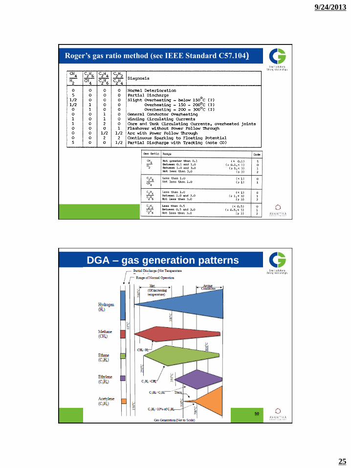
C. ROGERS RATIOS AND OTHER GUIDES ARE GOOD ANALYSING TOOLS
9/24/2013
25
Roger’s gas ratio method (see IEEE Standard C57.104)
DGA – gas generation patterns
50

9/24/2013
26
OIL TESTS
SOME GUIDELINES ON OIL TESTS RESULTS ARE GIVEN BELOW:
1. DIELECTRIC BREAKDOWN.
—INDICATES OIL QUALITY.
2. INTERFACIAL TENSION.
—MEASURE OF CONTAMINANTS LEVEL.
3. VISUAL CONDITION.
—PRESENCE OF FREE FLOATING CONTAMINANTS, SIGNS OF FREE WATER
4. NEUTRALIZATION NUMBER.
—DEGREE OF OXIDATION.
5. COLOUR.
—QUALITATIVE ASSESSMENT OF FAILING CHEMICAL PROPERTIES.
6. SPECIFIC GRAVITY.
—INDICATES IF OIL HAS BEEN CHEMICALLY ALTERED.
OIL TESTS (CONTINUED)
7. INHIBITOR CONTENT.
—IT SIGNALS THAT OIL QUALITY WILL DECAY
8. WATER CONTENT.
— CAUTION WITH INSULATION STRENGTH REDUCTION.
9. POWER FACTOR.
— INDICATION OF CONTAMINATION FROM WATER OR OXIDATION BY-
PRODUCTS.
10. PCB CONTENT.
— TO CHECK THAT PCB CONTENT IS BELOW REGULATORY GUIDELINES.
11. FURAN CONTENT.
— SUPPORTS DGA AND INDICATES PAPER QUALITY.
12. METALS CONTENT.
— SUPPORTS DGA AND FURAN CONTENT TEST
9/24/2013
27
Common problems
(a) No outage permitted
—If safe, operate the transformer with a safety radius (Some users use 50
feet radius based on their internal policies).
—If problem is on a few taps, leave LTC on a safe fixed tap.
—If problem is load related, reduce the load to a safe value.
—If problem is related to insulation and if safe, operate with insulation loss
of life.
—If problem is related to gassing and if safe, operate with gassing.
Common problems (cont’d…)
(b) Shorts by animals/birds
—Protect the live terminals, buses, etc., that can be shorted or grounded by
animals/birds by insulated covers.
—Check gas relay for gas accumulation.
—Check core ground and clamp ground.
—Measure windings insulation resistance.
—Check ratio of windings.
—Do a DGA.
—Check which protection has operated, this will give a clue on the healthiness of
the transformer..

9/24/2013
28
Common problems (cont’d…)
Gassing
—Check the age of the transformer to determine that gas levels are in line with the
age.
—Check the load. Load may be more than the safe designed value.
—Check the voltage. High voltage will cause over fluxing and saturation problems.
—Check the tap changer operation.
—Reduce load if gassing is load related.
—Do a DGA at regular intervals to determine the rate of gassing.
Common problems (cont’d…)
(d) Oil leaks
—If possible do temporary fixing and correct at the proper time.
—Based on the age of the transformer, amount of leaks etc., re-gasketting is a
good idea.
—Clean the rust in time and prevent further rusting.
9/24/2013
29
Common problems (cont’d…)
(e) Bushing failure
—Clean dust and salt coating on porcelains at regular intervals.
—Based on how old the bushing is, monitor capacitance and power factor at
regular intervals.
—Do not neglect bushing problems. Bushing problems could lead to catastrophic
failure.
—If bushings are in bus ducts or cable boxes, maintain proper ventilation.
—Based on the top oil temperature and the maximum current check that the draw
lead size is adequate.
—During regular intervals of power factor measurements on the transformer (
windings and bushings together) if any readings are suspicious then isolate the
bushings and measure power factor and capacitance of the bushings and
compare with bench mark readings.
Common problems (cont’d…)
(f) Malfunction of lightning arrestors and grounds
— perform checks at regular intervals.

9/24/2013
30
Common problems (cont’d…)
(g) Overloading
—Check the limitations with the transformer manufacturer.
—Items to be checked for overload are:
• Windings.
• Leads.
• Oil temperature.
• Tap changer.
• Bushings and bushing turrets.
• Internal magnetic shields.
• Over heating of parts due to increase in leakage flux at higher loads.
Common problems (cont’d…)
(h) Moisture
—Maintain the gel in the breather properly.
—Check at regular intervals the water content in the oil.
—Check power factor at regular intervals.
—Check for cracks on the tank through which water can go in to the tank.
—Check for damages in gasket joints through which water can go in to the
transformer.
—Check for water content in top-up oil.

9/24/2013
31
Major Problems
(a) Hot joints
—At design review stage user should check the design of all current carrying parts
and the shop practices to avoid potential problems during the life of the
transformer.
—User should specially check the joints during the manufacture so that no hot
joints will be developed during the operation.
—Special attention should be given to bolted joints so that they will not become
loose during the operation.
—Take precautions to avoid oxide film formation on the surfaces of current carrying
parts.
—Monitoring DGA at regular intervals will aid the detection of hot joints.
—At regular intervals check gas relay for gas accumulation.
Major Problems (cont’d…)
(b) Loose connections
—During manufacture, specially before tanking, all the bolted connections should
be checked for looseness.
— The crimped connections need to be checked for full engagement of the lead
with the connector,
—DGA at regular intervals is a good tool in detecting loose connections.
—At regular intervals check the gas relay for gas accumulation.
—Measure windings resistances and compare with bench mark readings.

9/24/2013
32
Major Problems (cont’d…)
c) Insulation degradation/failure
—During design review user should go through the insulation design to avoid
problems during the operation.
—During the design review user should also check the voltage stress verses
strength during operation and also during
factory testing in all the insulating materials (pressboard, paper etc,).
—Temperature rise of parts in contact with insulation should be limited to the safe
values stated in ANSI.
—All current carrying parts, specially the leads should have proper cooling to avoid
hot spots.
—Avoid moisture entering the transformer.
—Power Factor and other similar tests at regular intervals will indicate the
degradation of the insulation.
Major Problems (cont’d…)
(d) Failure of bushing current transformers (CTs)
—Check that the CTs have adequate cooling.
—Bushing turrets should be properly designed with non-magnetic inserts or with
non-magnetic steel where necessary to avoid hot spots. Hot spots on bushing
turrets will deteriorate the insulation on the CTs fast.
—Check the type of insulation materials in the CTs that their safe temperature limit
is well above the temperatures the CTs
experience during the operation.
—Check terminal boards used to bring-out CT leads that no leaks will be
developed.
—Check that the insulation used on the CT leads inside the transformer is
compatible with hot transformer oil.
9/24/2013
33
Major Problems (cont’d…)
(e)Hot spots on tank etc.
—Do thermo-vision scan regularly on the tank and at the bushing connections.
—During manufacture of the transformer user to check that tank shields are
properly designed and installed.
—Based on the current, the bushings turrets should be correctly designed to avoid
hot spots during the operation. Where
necessary correct length of non-magnetic material inserts should be placed in
the turrets or if needed the bushing turrets
should be made with non-magnetic material.
—Bushing connections to have proper hardware, specially if two different materials
(copper and aluminum) are bolted together..
Major Problems (cont’d…)
(f) Design and workmanship
—Purchase the transformers from the proven companies.
—Order should not be based on the price alone.
—User to have tender review and design review meetings with the manufacturer.
—User to inspect at different stages of the manufacturing and during testing.
—Availability of immediate and quality service is a big factor in transformer life
cycle cost.
9/24/2013
34
Major Problems (cont’d…)
(g) Oil aging
—Check the oil quality at regular intervals.
—Take timely corrective action to restore oil quality.
—Have a policy to grade the oils. Based on the transformer highest voltage use a
specific grade of the oil.
—Top-up oil must meet all the requirements of the oil during the first filling.
68
Thank you