make an inexpensive dual deployment rocket · ways check your cg/cp relationship after adding...
TRANSCRIPT

I S S U E 2 5 8 A P R I L 6 , 2 0 1 0
Apogee Components, Inc. — Your Source For Rocket Supplies That Will Take You To The “Peak-of-Flight”3355 Fillmore Ridge Heights
Colorado Springs, Colorado 80907-9024 USAwww.ApogeeRockets.com e-mail: [email protected]
Cover Photo: Mad Cow’s Super DX3 rocket kit. Get your’s today at:
www.ApogeeRockets.com/Madcow_Super_DX3.asp
Make AnInexpensive Dual Deployment Rocket
Feature Article

Page 2 I S S U E 2 5 8 A P R I L 6 , 2 0 1 0
You can subscribe to receive this e-zine FREE at the Apogee Components web site (www.ApogeeRockets.com), or by sending an e-mail to: [email protected] with “SUB-SCRIBE” as the subject line of the message.
About this Newsletter Newsletter Staff
Writer: Tim Van MilliganLayout / Cover Artist: Tim Van MilliganProofreader: Michelle Mason
By By Mike Momenee
Continued on page 3
An Inexpensive Method of Making Your Rockets Dual Deploy
I don’t know about you, but as I proceed further into my hobby of rocketry, I keep hearing comedian Tim Allen’s voice from the TV show “Home Improvement” saying, “MORE POWER!” Most rockets are capable of using a va-riety of motors, with the more powerful motors sending the rocket higher. So naturally, I continue to use motors with ever-increasing “kick”.
The downside to that tendency is that the higher the rocket flies, the farther it may drift from the launch pad. Now, you could use a smaller diameter parachute than what is recommended by the rocket kit to cut down on drift, but you run the very real risk of a landing that is so hard that your rocket is damaged (I don’t recommend this!). And in my case, Tampa Tripoli launches on a large cattle ranch, with several water hazards lurking in the distance if your rocket drifts too far.
One of the really neat things that has changed since my entry into rocketry in the late 1960’s is the advent of parachute dual deployment via tiny altimeter/controllers, like the PerfectFlite Hi-Alt 45K sold by Apogee Compo-nents. There are a number of kits out there that allow for dual deployment, or in my case, I enjoy making scratch-built dual deploy rockets.
Just to backtrack a bit, dual deployment, as nicely described at Apogee’s website, “deploy(s) two parachutes out of the rocket. One at apogee (a small one), and another when the rocket is closer to the ground (a BIG chute). This allows the rocket to come down close to the pad so you don’t have to walk far”.
The first parachute deployed, called the drogue chute, is usually initiated by either the motor’s ejection charge, or by the altimeter’s sensing of apogee and in turn firing a black power charge to eject the drogue chute. The pur-pose of the small drogue chute is to bring the rocket down relatively quickly, at approximately 60 feet per second (fps), so that it doesn’t drift too far before the main parachute is deployed.
The second chute deployed is the main chute, which you of course already have as part of your rocket. At a pre-
determined altitude as set by you on the altimeter/controller (often between 1,000 and 400 feet Above Ground Level- “AGL”) the altimeter fires the second “event”, igniting the second black powder charge and deploying the main chute. This larger chute brings your rocket to earth safely, usually at between 15 and 25 fps.
Figure 1 gives you a good schematic of what a typical dual deployment rocket looks like after the main parachute deploys.
Figure 1: The arrangement of parts in a traditional “dual-deployment” rocket. Photo by Kenneth Brown.
The immediate statement you probably are making right now is, “But my rocket doesn’t separate into three pieces like the photo”. I too have a number of 2.56” diam-eter and 3” diameter rockets that are single deploy rockets, but which I’d like to use with much more powerful H and
Main Chute
Compartment for Electronics
Small Drogue Chute

Page 3I S S U E 2 5 8 A P R I L 6 , 2 0 1 0
Inexpensive Dual Deployment RocketsContinued from page 2
Continued on page 4
I motors. Again, the problem is that they may drift too far because of the higher altitude they will achieve. And I really didn’t want to start cutting my rockets to create a dual de-ploy rocket; what if I want to fl y them again in single deploy confi guration?
Well, there are several commercially-available products on the market right now which effectively convert your ex-isting rocket into a dual deploy rocket. One that I own and absolutely love is called Tender Descender. But because I also enjoy the challenge of making rocket-related devices from rocket parts I have around the house, I decided to try to create a homemade main chute deployment device which could turn my existing rockets into dual deploy rock-ets.
First, you will need an altimeter/controller. Some of you may already have one in your dual deploy rockets. Others may have been thinking about purchasing one, but didn’t have the project that pushed you to order one. I personally like the PerfectFlite Hi-Alt 45K, which can fi re an “event’ at both apogee and at a user-settable main chute deployment “event” altitude (400, 700, 1,000 or 1,300 AGL)
This is the one item that is admittedly costly. But if you are planning to move into higher power rocketry, you’ll want to purchase one eventually anyway.
Next, if your rocket doesn’t already have one, you’ll need to create a payload bay to house the altimeter/control-ler. Since I’m always fl ying camcorders, I simply replaced
the coupler which connects the camcorder section to the rocket body section with a sealed-from-ejection-gases (secured with wing nuts) payload bay. I won’t go into the details of making a payload bay here, but Apogee does sell pre-made ones if you’d prefer. As a fi nal note here, AL-WAYS check your CG/CP relationship after adding weight and/or length to your rocket. I use the Rocksim program.
Ok- what we are about to create is a closed-at-one-end, split-in-half tensioned cylinder that will house the main parachute, and will reside inside the body tube where your main chute currently goes. The cylinder will be held shut by a knotted piece of 20# test monofi lament fi shing line ($2.50 at Wal-Mart) around its circumference. The deployment of the drogue chute will also push this closed cylinder out of the body tube. The cylinder will open, as triggered by the altimeter’s “main chute event” at your prescribed altitude via a Quest Q2G2 igniter which instantly burns through the fi shing line, allowing the tensioned cylinder to spring open and the chute to essentially fall out and open as the rocket is descending at approximately 60 fps under the drogue chute’s controlled but fast descent.
What you’ll be making will look like the brown cylinder hanging from below the red camcorder section as shown in Figure 2. The pink thing peaking out of the top of the cyl-inder is a parachute. The green wires leading up from the cylinder to the payload bay just below the red camcorder section electrically connect the altimeter/controller with the cylinder. The yellow Kevlar cord hanging down from the
Altimeter One
ww
w.A
pogeeRock
ets.co
mYour Source For Everything
Rock
etry
• Records peak altitude up to 29,000 feet (ASL)• Rechargable battery. Just plug it into a USB
port on your computer to recharge.• Small size: Fits easily in a 18mm diameter
tube, and weighs only 7 grams.• Rock-solid design. No need to protect it by
putting it in a separate payload bay. Just clip it to the nose cone or shock cord.
• Easy-to-read LCD display. No need to count beeps.
“The one altimeter you’ll use in every rocket you fl y.”
ww
w.A
pogeeRock
ets.co
mYour Source For Everything
Rock
etry
ww
w.A
pogeeRock
ets.co
mYour Source For Everything
Rock
etryCom
ing
May, 2010
Finally... A simple to use device that “shows” you how high your rocket went.
Quarter shown for size comparison

Page 4 I S S U E 2 5 8 A P R I L 6 , 2 0 1 0
Inexpensive Dual Deployment RocketsContinued from page 3
bottom of the cylinder is the shock cord, which connects to the screw eye in the base of the payload bay and leads down to the rocket body (out of the photo).
First, Cut the Cylinder
For a 2.56” diameter rocket, I used a 2” diameter motor mount tube I had, which I cut to 6” in length. For a 3” diam-eter rocket, I used a 2.56” dia. coupler which was 6” long. I
drew four lines down the length of the tube using a fi n guide as shown in Figure 3.
Then, cut the cylinder in half, using two of the lines as cutting guides like you see in Figure 3. I like to use a razor saw shown in Figure 4.
Cutting and Gluing the Side Guides
Using another section of tube of the same diameter and length, cut two 3/8” wide pieces that we’ll use as guides to align the two sections together when the device is in the closed position. See Figure 5.
Glue them to either side of one section, with 1/8” ex-tending past the edge of the cylinder half as seen in Figure
Continued on page 5
ww
w.A
pogeeRock
ets.co
m
We’re Paying CashFor Great Articles for This Newsletter
Are you a writer looking for some serious pocket change? We’re pay-ing up to $350 for good how-to articles for this newsletter. If you’re interested, see our submission guidelines on the Apogee web site.
www.ApogeeRockets.com/Newsletter_Guidelines.asp
Figure 2: A simplifi ed dual-deployment rocket.
Figure 3: Draw lines along the tube using a fi n guide.
Figure 4: Cut the tube in half. You may need to use a razor saw if the tube is tough. Clamping it to the work table as shown is a great idea.
Page 5I S S U E 2 5 8 A P R I L 6 , 2 0 1 0
Inexpensive Dual Deployment RocketsContinued from page 4
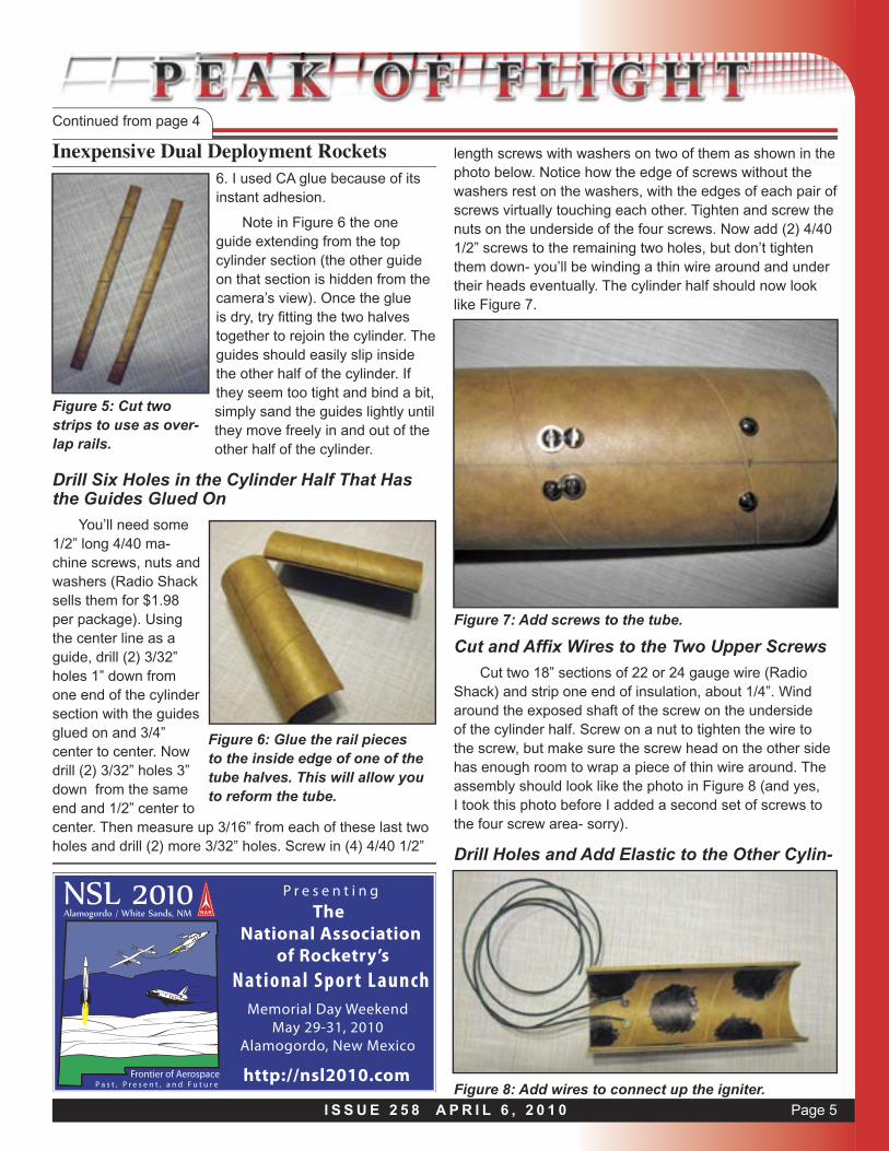
6. I used CA glue because of its instant adhesion.
Note in Figure 6 the one guide extending from the top cylinder section (the other guide on that section is hidden from the camera’s view). Once the glue is dry, try fi tting the two halves together to rejoin the cylinder. The guides should easily slip inside the other half of the cylinder. If they seem too tight and bind a bit, simply sand the guides lightly until they move freely in and out of the other half of the cylinder.
Drill Six Holes in the Cylinder Half That Has the Guides Glued On
You’ll need some 1/2” long 4/40 ma-chine screws, nuts and washers (Radio Shack sells them for $1.98 per package). Using the center line as a guide, drill (2) 3/32” holes 1” down from one end of the cylinder section with the guides glued on and 3/4” center to center. Now drill (2) 3/32” holes 3” down from the same end and 1/2” center to center. Then measure up 3/16” from each of these last two holes and drill (2) more 3/32” holes. Screw in (4) 4/40 1/2”
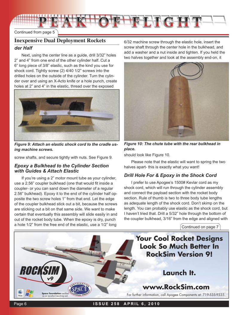
length screws with washers on two of them as shown in the photo below. Notice how the edge of screws without the washers rest on the washers, with the edges of each pair of screws virtually touching each other. Tighten and screw the nuts on the underside of the four screws. Now add (2) 4/40 1/2” screws to the remaining two holes, but don’t tighten them down- you’ll be winding a thin wire around and under their heads eventually. The cylinder half should now look like Figure 7.
Discovery
United States
P r e s e n t i n gThe
National Association of Rocketry’s
National S por t L aunchMemorial Day Weekend
May 29-31, 2010Alamogordo, New Mexico
http://nsl2010.com
Figure 5: Cut two strips to use as over-lap rails.
Figure 6: Glue the rail pieces to the inside edge of one of the tube halves. This will allow you to reform the tube.
Cut and Affi x Wires to the Two Upper Screws
Cut two 18” sections of 22 or 24 gauge wire (Radio Shack) and strip one end of insulation, about 1/4”. Wind around the exposed shaft of the screw on the underside of the cylinder half. Screw on a nut to tighten the wire to the screw, but make sure the screw head on the other side has enough room to wrap a piece of thin wire around. The assembly should look like the photo in Figure 8 (and yes, I took this photo before I added a second set of screws to the four screw area- sorry).
Drill Holes and Add Elastic to the Other Cylin-
Figure 7: Add screws to the tube.
Figure 8: Add wires to connect up the igniter.
Page 6 I S S U E 2 5 8 A P R I L 6 , 2 0 1 0
Continued on page 7
Inexpensive Dual Deployment RocketsContinued from page 5
der Half
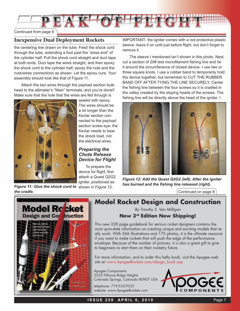
Next, using the center line as a guide, drill 3/32” holes 2” and 4” from one end of the other cylinder half. Cut a 6” long piece of 3/8” elastic, such as the kind you use for shock cord. Tightly screw (2) 4/40 1/2” screws into the drilled holes on the outside of the cylinder. Turn the cylin-der over and using an X-Acto knife or a hole punch, create holes at 2” and 4” in the elastic, thread over the exposed
6/32 machine screw through the elastic hole, insert the screw shaft through the center hole in the bulkhead, and add a washer and a nut inside and tighten. If you held the two halves together and look at the assembly end-on, it
Space Foundation certifi ed as an excellent teaching aid. For further information, call Apogee Components at: 719-535-9335.
www.RockSim.comv9
Your Cool Rocket Designs Look So Much Better In
RockSim Version 9!
Launch It.
Figure 9: Attach an elastic shock cord to the cradle us-ing machine screws.
screw shafts, and secure tightly with nuts. See Figure 9.
Epoxy a Bulkhead to the Cylinder Section with Guides & Attach Elastic
If you’re using a 2” motor mount tube as your cylinder, use a 2.56” coupler bulkhead (one that would fi t inside a coupler- or you can sand down the diameter of a regular 2.56” bulkhead). Epoxy it to the end of the cylinder half op-posite the two screw holes 1” from that end. Let the edge of the coupler bulkhead stick out a bit, because the screws are sticking out a bit on that same side. We want to make certain that eventually this assembly will slide easily in and out of the rocket body tube. When the epoxy is dry, punch a hole 1/2” from the free end of the elastic, use a 1/2” long
should look like Figure 10.
Please note that the elastic will want to spring the two halves apart- this is exactly what you want!
Drill Hole For & Epoxy in the Shock Cord
I prefer to use Apogee’s 1500# Kevlar cord as my shock cord, which will run through the cylinder assembly and connect the payload section with the rocket body section. Rule of thumb is two to three body tube lengths as adequate length of the shock cord. Don’t skimp on the length. You can probably use elastic as the shock cord, but I haven’t tried that. Drill a 5/32” hole through the bottom of the coupler bulkhead, 3/16” from the edge and aligned with
Figure 10: The chute tube with the rear bulkhead in place.
Page 7I S S U E 2 5 8 A P R I L 6 , 2 0 1 0
Inexpensive Dual Deployment RocketsContinued from page 6
the centering line drawn on the tube. Feed the shock cord through the tube, extending a foot past the “wires end” of the cylinder half. Pull the shock cord straight and duct tape at both ends. Duct tape the wires straight, and then epoxy the shock cord to the cylinder half, epoxy the nuts and the nuts/wires connections as shown. Let the epoxy cure. Your assembly should look like that of Figure 11.
Attach the two wires through the payload section bulk-head to the altimeter’s “Main” terminals, and you’re done!! Make sure that the hole that the wires are fed through is
sealed with epoxy. The wires should be a bit longer than the Kevlar section con-nected to the payload section screw eye- the Kevlar needs to bear the shock load, not the electrical wires.
Preparing the Chute Release Device for Flight
To prepare the device for fl ight, fi rst attach a Quest Q2G2 igniter, positioned as shown in Figure 12.
IMPORTANT- the igniter comes with a red protective plastic sleeve- leave it on until just before fl ight, but don’t forget to remove it
The sleeve I mentioned isn’t shown in this photo. Next, cut a section of 20# test monofi lament fi shing line and tie it around the circumference of closed device- I use two or three square knots. I use a rubber band to temporarily hold the device together, but remember to CUT THE RUBBER BAND OFF AFTER TYING THE LINE SECURELY. Center the fi shing line between the four screws so it is cradled in the valley created by the sloping heads of the screws. The fi shing line will be directly above the head of the igniter. I
Continued on page 8
Model Rocket Design and ConstructionBy Timothy S. Van Milligan
New 3rd Edition Now Shipping!
Apogee Components3355 Fillmore Ridge HeightsColorado Springs, Colorado 80907 USA
telephone: 719-535-9335website: www.ApogeeRockets.com
This new 328 page guidebook for serious rocket designers contains the most up-to-date information on creating unique and exciting models that re-ally work. With 566 illustrations and 175 photos, it is the ultimate resource if you want to make rockets that will push the edge of the performance envelope. Because of the number of pictures, it is also a great gift to give to beginners to start them on their rocketry future.
For more information, and to order this hefty book, visit the Apogee web site at: www.ApogeeRockets.com/design_book.asp
Figure 11: Glue the shock cord to the cradle.
Figure 12: Add the Quest Q2G2 (left). After the igniter has burned and the fi shing line released (right).

Page 8 I S S U E 2 5 8 A P R I L 6 , 2 0 1 0
Inexpensive Dual Deployment RocketsContinued from page 7
use strapping tape to secure the igniter in place, as well as on ONLY ONE SIDE of the fishing line, as shown in Figure 12 on the right-side photos. The photo is after a flight; you can see where the line has been burned though, just at the end of the spent igniter:
Please Remember:
l If you don’t cut the rubber band off used to temporar-ily hold the device together while tying the fishing line, it won’t open in flight
l If you don’t remove the red protective sleeve from the igniter, it won’t be able to burn through the fishing line. I pull off the sleeve just before inserting the device into the rocket body tube to protect the head
l If you tape the fishing line on BOTH SIDES of the four screws, the device won’t be able to spring open
I know these are common sense items, but during the excitement of the moment, they could possibly be over-looked.
So…How Well Does It Work?
Once I figured out that the Quest igniter (www.apog-eerockets.com/igniters.asp) was THE way to burn through the fishing line, it has worked 100% of the time in flight tests as well as ground tests. I started this project with Continued on page 9
Continued on page 10 Staging Electronics• Designed to ignite the top motor in two-stage rockets.
• Provides an easy way to stage composite propel-
lant motors
ww
w.A
pogeeRock
ets.co
m
• Fires off igniters after a preprogrammed amount of
time following liftoff• G-switch senses liftoff and
insures against a false launch-detection
• Small, lightweight design is great for skinny rockets
• Easy-to-use, and will fire off any ig-niter, including clusters!
www.ApogeeRockets.com/Staging_Timer.aspBattery, battery connector, mounting board and igniter are not incuded.
the idea of burning through the fishing line with nichrome wire. It works perfectly if you hook a 9V battery and com-plete the circuit for a few seconds. However, a flight test showed (and my newly-created vacuum chamber www.ApogeeRockets.com/education/downloads/Newsletter256.pdf confirmed), that the 0.5 second firing current from most altimeter/controllers isn’t long enough to heat nichrome wire hot enough to burn through the fishing line. So my “Aha” moment was trying the Quest igniter, which I already knew would ignite black powder ejection charges via an altimeter/controller.
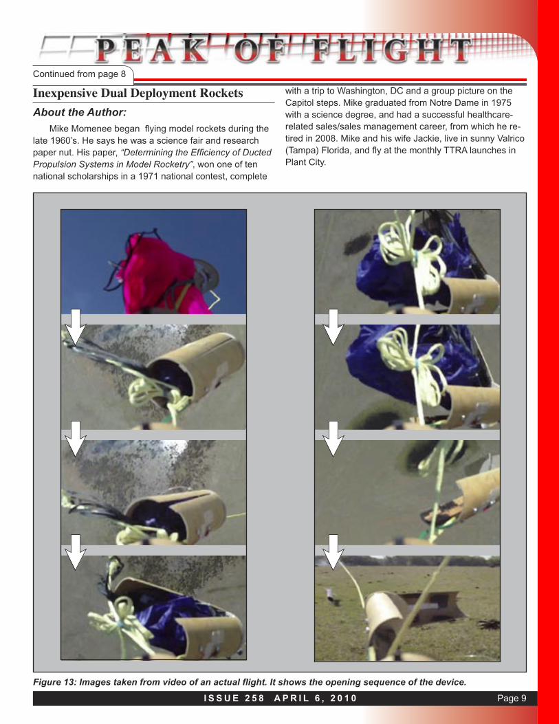
The video captures shown on the next page are from a recent flight, which show the moment of the pink drogue chute deployment, as well as the opening of the main chute release device at 500 feet AGL:
By the way: the brown things in this last vidcap are cow “patties”- just something we in Tampa need to watch out for during recovery.
I’m sure that there are many other ways to accomplish dual deployment from a single deploy rocket. I’m equally sure that many of you would have some great suggestions as to how to improve on my design. I hope that this exer-cise will get you thinking about this or some other area of what I would term “slightly experimental” rocketry. Have fun with it!
Page 9I S S U E 2 5 8 A P R I L 6 , 2 0 1 0
Inexpensive Dual Deployment RocketsContinued from page 8
About the Author:
Mike Momenee began flying model rockets during the late 1960’s. He says he was a science fair and research paper nut. His paper, “Determining the Efficiency of Ducted Propulsion Systems in Model Rocketry”, won one of ten national scholarships in a 1971 national contest, complete
with a trip to Washington, DC and a group picture on the Capitol steps. Mike graduated from Notre Dame in 1975 with a science degree, and had a successful healthcare-related sales/sales management career, from which he re-tired in 2008. Mike and his wife Jackie, live in sunny Valrico (Tampa) Florida, and fly at the monthly TTRA launches in Plant City.
Figure 13: Images taken from video of an actual flight. It shows the opening sequence of the device.