making modern living possible - danfoss assistassistyou.danfoss.co.uk/pcmpdf/8585v01s7-03.pdf ·...
TRANSCRIPT

FP9757-Day Electronic Programmer
Installation GuideDanfoss Heating
MAKING MODERN LIVING POSSIBLE

FP9752
For a large print version of these instructions please call Marketing on 0845 121 7400.
Danfoss can accept no responsibility for possible errors in catalogues, brochures, and other printed material. All trademarks in this material are property of the respective companies. Danfoss and the Danfoss logotype are trademarks of Danfoss A/S. All rights reserved.
®
Certification Mark

Danfoss Heating 3
GB
Installation Instructions
FP9757 Day Electronic Programmer
Index
1.0 Installation Guide .....................................................................................4
2.0 System Overview .......................................................................................4
3.0 Installation ...................................................................................................4 3.1 DIL Switch Settings ...........................................................................4 3.2 New Installations................................................................................5 3.3 Existing Installations .........................................................................8 3.4 Wiring .....................................................................................................9 3.5 230 Vac Fully Pumped System - Zone Valves ...........................9 3.6 230 Vac Controlled Gravity Hot Water ..................................... 10 3.7 230 Vac Fully Pumped System - Mid-Position Valves ......... 10 3.8 Wiring Conversions ........................................................................ 11

FP9754
GBSpecifi cation
Power supply 230 Vac ± 15%, 50/60 Hz
Switching action 2 x SPDT voltage free, Type 1BS
Switch rating 10-230 Vac, 3(1)A
Battery back-up 24 hours minimum
Timing Accuracy ±1 min/month
Setting/Running Accuracy ±1 minute
Max. Ambient Temperature 45°C
Dimensions, mm (W, H, D) 148 x 96 x 42
Design standard EN 60730-2-7
Control Pollution Situation Degree 2
Rated Impulse Voltage 2.5kV
Ball Pressure Test 75°C
1.0 Installation Guide
2.0 System Overview
Please Note:This product should only be installed by a qualifi ed electrician or competent heating installer and should be in accordance with the current edition of the IEEE wiring regulations.
Before mounting the unit, ensure the 4 DIL switches on the rear of the unit have been moved to the required settings.
RIGHTLEFT
TOP
MK.9
SET
PUM
PEDG
RAVITY
7 DAY/24 H
R5/2 D
AY
24 HR
7 DAY
3.0 Installation3.1 DIL Switch Settings

Danfoss Heating 5
GB
MK.9 or SET The FP975 is supplied fi tted with a Danfoss Randall SET wallplate. However the FP975 will also mount directly onto a Danfoss Randall MK.9 wallplate without the need for wiring changes. However when used with existing MK.9 wallplates the left hand switch must be set in the MK.9 position to re-confi gure the time control to match MK.9 wiring connections.
PUMPED or GRAVITYWhen this switch is in the PUMPED position the Heating and Water outputs are UNLINKED. When in the GRAVITY position the Water output is LINKED to the Heating output so that whenever the Heating is ON the Water will also be ON regardless of the Water programme.
Place the switch in the PUMPED position if the system being controlled is a) fully pumped with a mid-position valve, b) fully pumped with a two port zone valve in each circuit, c) GRAVITY Hot Water, PUMPED Heating with a two port zone valve with SPDT auxiliary switch in the gravity primary circuit (and wired in accordance with diagrams on pages 9-10).
Place the switch in the GRAVITY position if the system being controlled is a) fully pumped, but with only a single two port zone valve in the Heating circuit, b) GRAVITY Hot Water, PUMPED Heating with no zone valves.
7 Day, 5/2 Day or 24 HourWhen both switches are in the 7 DAY position each day of the week may be programmed with diff erent ON/OFF times. When the switch is in the 5 DAY/2 DAY position, weekdays (Mon-Fri) can be programmed with one set of ON/OFF times, and weekends (Sat-Sun) can be programmed with a diff erent set. When both switches are in the 24 hour position the same set of times will be repeated in every 24 hour period.
3.2 New Installation
1. Fix the wallplate to the wall or plaster box as required. When fi xing the wallplate note that the terminals are at the top,
and the vertical centre line of the unit lies between terminals N and L.
2. Surface cables can only enter from below the unit. If mounted on a plaster box, cables can enter from the rear through the aperture in the wallplate.

FP9756
GB
3. The FP975 off ers direct plug-in replacement to the following models (see below):
Man
ufa
ctu
rer
Mo
del
Fully
Pu
mp
ed
Syst
ems
Pum
ped
/G
ravi
ty S
elec
tor
Posi
tio
n
Gra
vity
H.W
. Sy
stem
s Pu
mp
ed/
Gra
vity
Sel
ecto
r Po
siti
on
Wal
lpla
te
Typ
e M
od
e Sw
Po
siti
on
Dan
foss
Ran
dall
FP97
5Pu
mp
edG
ravi
tySE
TSE
T
922
Unl
inke
dLi
nked
MK.
9M
K.9
972
Unl
inke
dLi
nked
MK.
9M
K.9
SET
2*U
nlin
ked
Link
edSE
TSE
T
SET
5U
nlin
ked
Link
edSE
TSE
T
Hor
stm
ann
Dia
dem
425
Pum
ped
Gra
vity
SET
SET
Tiar
a 42
5Pu
mp
edG
ravi
tySE
TSE
T
Tiar
a 52
5Pu
mp
edG
ravi
tySE
TSE
T
Tiar
a 52
7Pu
mp
edG
ravi
tySE
TSE
T
Dir
ect P
lug
-In
Up
gra
de
for
Exis
tin
g P
rog
ram
mer
s

Danfoss Heating 7
GB
IMPORTANT NOTEIf the timeswitch to be replaced is listed below it may be worth considering a FP715 Si as an alternative to the FP975. The FP715 Si off ers wallplate compatibility for those models listed below, although some re-wiring may be required.
If the new unit is replacing an existing time control having an incompatible wiring confi guration, then the wiring conversions (tables A and B, pages 12-15) will be of assistance.
4. For wiring connections please refer to diagrams on pages 9-10. Please note, the FP975 does not require an earth connection, although a terminal is provided for earth continuity purposes.
5. Ensure that the two retaining screws on the top of the timeswitch are fully unscrewed. Locate the retaining lugs on the bottom inside surface of the plug-in module under the wallplate base and hinge the unit upwards until the module is pressed fully against the top of the wallplate. Tighten the two screws on the top of the module to secure the module to the wallplate.
6. A small blanking plug is supplied to blank the unused recessed bottom fi xing screw.
7. Before setting the programmes the unit should be RESET by pressing the recessed button marked R/S. Ensure the mains power to the control circuit is switched on, and check the circuits as follows.
8. Use the (Hot Water) SELECT button to get to the ON mode to switch the hot water output ON. Adjust the cylinder thermostat and check the service operates correctly. Use the SELECT button to get to OFF mode and check that the service does not operate.
9. Use the (Heating) SELECT button to get to the ON mode to switch the heating output ON. Adjust any remote thermostat(s) and check that the service operates correctly. Use the SELECT button to get to OFF mode and check that the service does not operate.
MAKE MODELS
ACL LS2411, LS522, LS722, LP241, LP522, LP722
Drayton Tempus 3, Tempus 4, Tempus 7
Landis & Gyr RWB 2, RWB 2-9, RWB 200, RWB 252, RWB 20, RWB 40
Glowworm Mastermind
Potterton Mini-Minder

FP9758
GB
Ensure that the power to the existing unit is switched off prior to removal.
SYSTEMS RE-USING EXISTING WALLPLATEUse the table on page 6 to confi rm wallplate compatibility.
• If the existing wallplate is of the SET pattern, follow instruction 5-9 from the “New Installations” section.
• Should the existing product be a Danfoss Randall MK.9 time control the instructions below should be followed:
1. Remove and discard the white test point cover fi tted to the top of the MK.9 wallplate.
2. Slide the small switches on the rear of the module marked MK.9 - SET to the MK.9 position.
3. Ensure that the two retaining screws on the top of the timeswitch are fully unscrewed. Firmly press the module onto the wallplate and tighten the two screws on the top of the module. An additional fi xing screw to hold the bottom of the unit onto the wallplate is packed separately and must be fi tted. The screw should be placed into the recessed hole, beneath the programming fl ap, adjacent to the COPY button, screwed through the plastic retaining ring and securely tightened.
4. Follow steps 5-9 from the “New Installations” section.
SYSTEMS HAVING INCOMPATIBLE BACKPLATESFollow the “New Installations” instructions paying particular attention to item 3).
3.3 Existing Installation

Danfoss Heating 9
GB
3.4 Wiring
Always switch off mains fi rst and never fi t programmer to a live wallplate.
N/O
ON
T2E LINKALS 1 & 5
ON A SET LATE
N L 1 2 3 4 5 6
TIMER
OFFCOMDHW
ON
N/C
COMHTG
OFF
N/O N/C
3.5 230 Vac Fully Pumped System 2 x 2-port Zone Valves with Aux. Sw. PUMPED switch selection
N L 1 2 3 4 5 6
N
L
BOILER PUMP
ATC
DHW VALVE
HTG VALVE
RMT
Earths not shown. Ensure continuity throughout
MAINS fused 3A
DHW ON
DHW OFF
DHW COM
HTG ON
HTG OFF
HTG COM
HEAT PLAN
230 Vac
For 230 Vac systems link L, 2 & 5.
For Wiring Conversion tables see pages 12-15.

FP97510
GB
3.7 230 Vac Fully Pumped System 3-Port Mid-Position Valve PUMPED Switch Selection
N L 1 2 3 4 5 6
N
L
BOILERPUMP
ATC
RMT
MAINS fused 3A
DHW ON
DHW OFF
DHW COM
HTG ON
HTG OFF
HTG COM
HS3
HEAT SHARE
Earths not shown. Ensure continuity throughout
230 Vac
3.6 230 Vac Controlled Gravity Hot Water Pumped Heating System PUMPED Switch Selection
N L 1 2 3 4 5 6
N
L
BOILER PUMP
ATC
RMT
MAINS fused 3A
DHW ON
DHW OFF
DHW COM
HTG ON
HTG OFF
HTG COM
HP28C Earths not shown. Ensure continuity throughout
230 Vac

Danfoss Heating 11
GB
WIRING CONVERSIONS to be used when replacing the following programmers with the FP975. Some time controls are connected diff erently depending on the type of system they are controlling. Consult the column headed “NOTE This conversion ...” to determine whether Table A (pages 12-13) or Table B (pages 14-15) should be used. If in any doubt, contact our Technical Services Department before proceeding with the replacement.
3.8 Wiring Conversions See pages 12-15

FP97512
GB
Tab
le A
DA
NFO
SS R
AN
DA
LL
FP97
5 (S
ET M
OD
E)Fu
lly P
umpe
d Sy
stem
s - e
nsur
e Pu
mpe
d/G
ravi
ty s
witc
h is
in
‘Pum
ped’
pos
ition
MA
INS
WAT
ERH
EATI
NG
NO
TETh
is c
onv
ersi
on
ap
plie
s o
nly
if...
.
An
ad
dit
ion
al te
rmin
al
blo
ck m
ay b
e re
qu
ired
w
her
e th
ese
dis
con
nec
ted
lead
s (o
r p
airs
) sh
ou
ld b
e te
rmin
ated
NL
ON
COM
OFF
ON
COM
OFF
NL
12
34
56
LIN
K L
- 2 -
5A
BC
D
DA
NFO
SS R
AN
DA
LL 4
033
76
41
52
-3
HO
RSTM
AN
N 4
23,
AM
ETH
YST
7 &
10
2,3
15
-4
7-
68
HO
RSTM
AN
N 4
24 G
EM2,
31,
104
56
78
9Te
rmin
als
5,8
& 1
0 ar
e LI
NKE
D
HO
RSTM
AN
N L
EUC
ITE
423
& 4
242
13
54
67
8Te
rmin
als
5 &
7 a
re L
INKE
D
HO
NEY
WEL
L ST
669
NL
68
73
54
POTT
ERTO
N E
P200
0, E
P300
0N
L3
-1
45
2Pr
ogra
mm
e se
lect
ors
UN
LIN
KED
AB
CD
RAN
DA
LL 3
033
1,7
64
-5
2-
3
RAN
DA
LL 7
02N
L3
64
15
2
SAN
GA
MO
FO
RM 1
410
& 4
144,
56
13
28
-7
SAN
GA
MO
S40
9/1
N,1
,3L
2-
-5
--
6,4
SAN
GA
MO
S40
9/3
3,6
75
-4
1-
2

Danfoss Heating 13
GB
Tab
le A
co
nti
nu
edD
AN
FOSS
RA
ND
ALL
FP
975
(SET
MO
DE)
MA
INS
WAT
ERH
EATI
NG
NO
TETh
is c
onv
ersi
on
ap
plie
s o
nly
if...
.
An
ad
dit
ion
al te
rmin
al
blo
ck m
ay b
e re
qu
ired
w
her
e th
ese
dis
con
-n
ecte
d le
ads
(or
pai
rs)
sho
uld
be
term
inat
edN
LO
NCO
MO
FFO
NCO
MO
FF
NL
12
34
56
LIN
K L
- 2 -
5A
BC
D
SATC
HW
ELL
LIBR
A &
DH
P 22
011
26
78
34
5
SATC
HW
ELL
ET 1
401
& 1
451
12
76
84
35
SMIT
HS
IND
. CEN
TRO
LLER
90
12
5-
-4
--
36
SMIT
HS
IND
. CEN
TRO
LLER
100
0N
L3
-1
4-
2Pr
ogra
mm
e se
lect
ors
UN
LIN
KED
SWIT
CH
MA
STER
800
& 8
05N
L3
-4
1-
2
SWIT
CH
MA
STER
900
& 9
000
NL
3-
41
-2
Prog
ram
me
sele
ctor
s U
NLI
NKE
DA
BC
VEN
NER
CH
C/W
2 (W
ITH
STA
T)N
,2,4
L1
--
A/S
--
Use
d in
a s
yste
m h
avin
g in
dep
ende
nt c
ontr
ol o
f w
ater
and
hea
ting
A/S
3
VEN
NER
CH
C/W
2 (A
IR S
TAT
LIN
KED
)N
,2,4
L1
--
3-
-
VEN
NER
VEN
OTR
OL
80M
& 8
0PM
(W
ITH
AIR
STA
T)N
,3L
2-
1A
/S-
4A
/S5
VEN
NER
VEN
OTR
OL
80M
& 8
0PM
(A
IR S
TAT
LIN
KED
)N
,3L
2-
15
-4

FP97514
GB
Tab
le B
DA
NFO
SS R
AN
DA
LL
FP97
5 (S
ET M
OD
E)G
ravi
ty D
HW
, Pum
ped
Hea
ting
Syst
ems -
en
sure
Pum
ped/
Gra
vity
sw
itch
is in
‘Gra
vity
’ po
sitio
n
MA
INS
WAT
ERH
EATI
NG
NO
TETh
is c
onv
ersi
on
ap
plie
s o
nly
if...
.
An
ad
dit
ion
al te
rmin
al
blo
ck m
ay b
e re
qu
ired
w
her
e th
ese
dis
con
-n
ecte
d le
ads
(or
pai
rs)
sho
uld
be
term
inat
edN
LO
NCO
MO
FFO
NCO
MO
FF
NL
12
34
56
LIN
K L
- 2 -
5A
BC
D
DA
NFO
SS R
AN
DA
LL
102/
102E
/102
E5/1
02E7
53,
61
--
2-
-
HO
RSTM
AN
N 4
23 D
IAM
ON
D
POTT
ERTO
N 4
23N
L,1,
32
--
4-
-5
6
HO
RSTM
AN
N 4
24 D
IAM
ON
DN
L,1,
32
--
4-
-5
HO
RSTM
AN
N C
ORA
L 42
3 &
424
2,3
1BO
ILER
(8
)-
-A
IR
STAT
(8
)-
-4,
75
6
POTT
ERTO
N E
P200
0, E
P300
0N
L3
-1
45
2Pr
ogra
mm
e se
lect
ors
LIN
KED
AB
CD
DA
NFO
SS R
AN
DA
LL 3
060
& 3
020P
1,7
64
--
2-
-3
5
RAN
DA
LL 7
01N
L3
64
15
2
SAN
GA
MO
M5
410
FORM
44,
53
1,6
-2
8-
7
SAN
GA
MO
S40
9 FO
RMS
1 &
4N
,1,3
L2
--
5-
-6,
4
SAN
GA
MO
(EA
RLY
MO
DEL
) S41
0 FO
RM 4
N,2
L1,
3-
-4
--
1 &
3 a
re L
INKE
D
SATC
HW
ELL
LIBR
A1
26
78
34
5
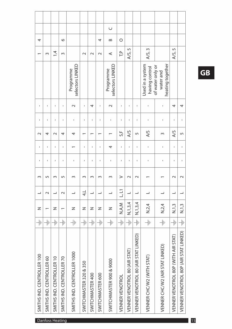
Danfoss Heating 15
GB
SMIT
HS
IND
. CEN
TRO
LLER
100
NL
3-
-2
--
14
SMIT
HS
IND
. CEN
TRO
LLER
60
12
5-
-4
--
3
SMIT
HS
IND
. CEN
TRO
LLER
10
NL
3-
-2
--
1,4
SMIT
HS
IND
. CEN
TRO
LLER
70
12
5-
-4
--
36
SMIT
HS
IND
. CEN
TRO
LLER
100
0N
L3
-1
4-
2Pr
ogra
mm
e se
lect
ors
LIN
KED
SWIT
CH
MA
STER
320
& 3
50N
4,L
3-
-1
--
2
SWIT
CH
MA
STER
400
NL
3-
-1
-4
2
SWIT
CH
MA
STER
600
NL
3-
-1
--
24
SWIT
CH
MA
STER
900
& 9
000
NL
3-
41
-2
Prog
ram
me
sele
ctor
s LI
NKE
DA
BC
VEN
NER
VEN
OTR
OL
N,A
,ML,
L1
V-
-S,
F-
-T,
PO
VEN
NER
VEN
OTR
OL
80 (A
IR S
TAT)
N,1
,3,4
L2
--
A/S
--
A/S
, 5
VEN
NER
VEN
OTR
OL
80 (A
IR S
TAT
LIN
KED
)N
,1,3
,4L
2-
-5
--
VEN
NER
CH
C/W
2 (W
ITH
STA
T)N
,2,4
L1
--
A/S
--
Use
d in
a s
yste
m
havi
ng c
ontr
ol
of w
ater
onl
y or
w
ater
and
he
atin
g to
geth
er
A/S
, 3
VEN
NER
CH
C/W
2 (A
IR S
TAT
LIN
KED
)N
,2,4
L1
--
3-
-
VEN
NER
VEN
OTR
OL
80P
(WIT
H A
IR S
TAT)
N,1
,3L
2-
-A
/S-
4A
/S, 5
VEN
NER
VEN
OTR
OL
80P
(AIR
STA
T LI
NKE
D)
N,1
,3L
2-
-5
-4

Part No. 8585v01s7-03 03/11
Danfoss Ltd.Ampthill RoadBedford MK42 9ER
Tel: 01234 364621Fax: 01234 219705Email: [email protected]: www.heating.danfoss.co.uk