malaya university ofstudentsrepo.um.edu.my/10026/8/shah_rizal.pdf · 2020. 2. 5. · chapter 1:...
TRANSCRIPT

DESIGN AND DEVELOPMENT OF AUTOMATION SYSTEM FOR PRECISION APPROACH PATH INDICATOR
(PAPI) IN AIRFIELD LIGHTING
SHAH RIZAL BIN MOHD SHAHER
FACULTY OF ENGINEERING UNIVERSITY OF MALAYA
KUALA LUMPUR
2018Univ
ersity
of M
alaya

DESIGN AND DEVELOPMENT OF AUTOMATION SYSTEM FOR PRECISION APPROACH PATH INDICATOR (PAPI) IN AIRFIELD LIGHTING
SHAH RIZAL BIN MOHD SHAHER
RESEARCH REPORT SUBMITTED IN PARTIAL FULFILMENT OF THE REQUIREMENTS FOR THE
DEGREE OF MASTER OF ENGINEERING (MECHATRONICS)
FACULTY OF ENGINEERING UNIVERSITY OF MALAYA
KUALA LUMPUR
2018 Univers
ity of
Mala
ya

ii
UNIVERSITY OF MALAYA
ORIGINAL LITERARY WORK DECLARATION
Name of Candidate: Shah Rizal bin Mohd Shaher
Matric No: KQF 160005
Name of Degree: Master of Engineering (Mechatronics)
Title of Project Paper/Research Report/Dissertation/Thesis:
DESIGN AND DEVELOPMENT OF AUTOMATION SYSTEM FOR
PRECISION APPROACH PATH INDICATOR (PAPI) IN AIRFIELD
LIGHTING
Field of Study: Automation
I do solemnly and sincerely declare that:
(1) I am the sole author/writer of this Work; (2) This Work is original; (3) Any use of any work in which copyright exists was done by way of fair
dealing and for permitted purposes and any excerpt or extract from, or reference to or reproduction of any copyright work has been disclosed expressly and sufficiently and the title of the Work and its authorship have been acknowledged in this Work;
(4) I do not have any actual knowledge nor do I ought reasonably to know that the making of this work constitutes an infringement of any copyright work;
(5) I hereby assign all and every rights in the copyright to this Work to the University of Malaya ( UM ), who henceforth shall be owner of the copyright in this Work and that any reproduction or use in any form or by any means whatsoever is prohibited without the written consent of UM having been first had and obtained;
(6) I am fully aware that if in the course of making this Work I have infringed any copyright whether intentionally or otherwise, I may be subject to legal action or any other action as may be determined by UM.
Candidate s Signature Date:
Subscribed and solemnly declared before,
Witness s Signature Date:
Name:
Designation:
Univers
ity of
Mala
ya

iii
ABSTRACT
Airfield Grounding lighting (AGL) is the aid for the pilot to take off and land, it
consists of the structure of lights, power supply, mounting systems and control from
the air traffic control tower to substation and to lights. AGL are divided into three
main parts, which are power supply, lighting and control system. In this project, we
focused only on the lighting part that gives an aid to the pilot for safe landing by
using a 3-degree slope of runway. It is called Precision Approach Path Indicator
(PAPI) which is the most important light in airfield lighting. PAPI is a valuable
visual aid that can provide precision direction for pilots when making a landing.
Normally PAPI is a single bar with four units located on the left side of a runway for
touch-down aiming point, whilst in some airports PAPI are installed in 2 bars on left
and right side. To maintain operational conditions and precision of the system, PAPI
must be calibrated once a year and maintenance must be carried out periodically. The
calibration is done by using special tools and manually adjust the angle of the PAPI as
instructed by the flight calibration team provided by the department of civil aviation
authority. While carrying out PAPI calibration, the access to the runway will be
blocked and all aircraft will be rescheduled. The inspection on PAPI is made by
checking each of PAPI angle as specified in ICAO annex 14 which are 2.50°, 2.83°,
3.17°and 3.50°. This is very time consuming as the calibration needs to be done
manually and extra man power is needed to communicate with aircraft calibration.
Also, if mis-align then consume time to re align. The more time taken to conduct this
exercise the more cost will be incurred to pay to the department of civil aviation
authority. In this project, an automated PAPI calibration system is designed by using
PAPI system and Leadscrew Stepper Motor on AutoCAD SOLIDWORKS. Then,
design ladder Diagram has been constructed to simulate operation of stepper motor
combined with PAPI system for automatic movement. Design model of Leadscrew
Univers
ity of
Mala
ya

iv
stepper motor is integrated on PAPI system and helped to move the PAPI up and down
(vertically) to adjust elevation angle of PAPI system. This design will allow automatic
adjustment of the system and subsequently it would reduce the cost of maintenance on
extra man power, special tools, safety and the most important factor is less time
consuming.
Univers
ity of
Mala
ya

v
ABSTRAK
Semua cahaya dalam lampu Airfield Grounding (AGL), dengan sistem bekalan
kuasa, sistem pelekap dan sistem kawalan masing-masing yang digunakan untuk
"penglihatan" menyokong pendaratan, pergerakan, teksi dan pesawat udara. AGL
boleh dibahagikan kepada tiga bahagian, seperti bekalan kuasa, pencahayaan,
Sistem Kawalan Pencahayaan Airfield (ALCS & ILCMS). Dalam projek ini, kami
menumpukan Precision Approach Path Indicator (PAPI) salah satu cahaya dalam
lampu lapangan terbang. PAPI adalah bantuan visual berharga yang dibangunkan
untuk memberikan arahan ketepatan untuk juruterbang apabila membuat
pendekatan ke landasan kapal terbang. Penyokong sistem PAPI membantu
penambah baikan berikut seperti peralihan cepat warna putih / merah yang tepat
dari satu warna ke yang lain. Titik merentas satu bar, panduan pelbagai laluan
(maklumat tambahan). Untuk mengekalkan keadaan operasi dan ketepatan sistem,
penyelenggaraan dijangka dijalankan menggunakan misalnya mesin terbang atau
platform kerja mengangkat. Menyekat akses ke landasan, pemeriksaan PAPI dibuat
dengan mensimulasikan pendekatan sinusoidal untuk mengesahkan sudut ambang
dan memastikan pematuhan dengan peraturan. Oleh itu, lapangan terbang itu
semestinya menutup jalan landasan, memakan masa, memaksimumkan logistik
rumit dan mengambil risiko dengan menggerakkan pengendali di udara dan
landasan. Pada masa ini untuk menyesuaikan sudut ketinggian, memerlukan alat
khas dan tenaga manusia tambahan untuk berkomunikasi dengan penentu ukuran
pesawat dan menyesuaikan sudut menggunakan alat dan manual. Terdapat lebih
banyak masa, memakan kos yang lebih banyak bagi pihak berkuasa penerbangan
awam jabatan. Juga, jika salah menyelaraskan kemudian mengambil masa untuk
menyelaraskan semula. Dalam projek ini, sistem PAPI dan Leadscrew Stepper
Univers
ity of
Mala
ya

vi
Motor direka pada AutoCAD SOLIDWORKS. Diagram Ladang juga merancang
untuk memeriksa Operasi Simulasi motor stepper yang digabungkan dengan sistem
PAPI. Model reka bentuk stepper motor Leadscrew bersepadu pada sistem PAPI
dan membantu menggerakkan PAPI ke atas dan ke bawah (menegak) untuk
menyesuaikan sudut ketinggian sistem PAPI. Reka bentuk ini membantu membuat
sistem automatik dan ia dapat mengurangkan kos tenaga manusia tambahan, alat
khas, kos dan faktor yang paling penting menjimatkan masa.
Univers
ity of
Mala
ya

vii
ACKNOWLEDGEMENTS
Firstly, I would like to take this opportunity to express my profound gratitude and deep
regard to my supervisor, Associate Prof. Ir. Dr. Mahidzal Bin Dahari for his guidance and
constant encouragement throughout the duration of this research project. His advices for
my research project proved to be a landmark effort towards the success of my project.
Next, I am deeply indebted to my parents for their continuous encouragement and
support. To my mother I really loves you, always pray for you. For my father whom has
passed away in 2016, I really respect you and I am here because all of your guide. May
Allah blessed you. His loves and cares has been driving force for this endeavor and no
words of gratitude are enough.
Special thanks to my wife, families and sisters for their unconditional love and support.
Thanks, are also due to all my friends, relatives, and colleagues for their support.
Finally, I would like to pay special thankfulness to faculty of engineering for approving
my research project and providing unlimited sources for me.
Univers
ity of
Mala
ya

viii
TABLE OF CONTENTS
Abstract............................................................................................................................ iii
Abstrak .............................................................................................................................. v
Acknowledgements ........................................................................................................ vii
Table of Contents .......................................................................................................... viii
List of Figures ................................................................................................................. xi
List of Tables ................................................................................................................. xiv
List of Symbols and Abbreviations ................................................................................. xv
CHAPTER 1: INTRODUCTION .................................................................................. 1
1.1 Introduction .............................................................................................................. 1
1.2 Problem Statement of Research: .............................................................................. 2
1.3 Objective of Research: ............................................................................................. 4
1.4 Scope of Project ....................................................................................................... 4
1.5 Thesis Organization ................................................................................................. 4
CHAPTER 2: LITERATURE REVIEW ...................................................................... 5
2.1 PAPI Study ............................................................................................................... 5
2.2 Technical Notes on PAPI ......................................................................................... 8
2.3 Back ground of PAPI ............................................................................................. 11
2.4 The Requirement .................................................................................................... 11
2.5 Settings angles ....................................................................................................... 12
2.6 Obstacle Clearance Surface ................................................................................... 14
2.7 Design of the PAPI unit ......................................................................................... 15
2.8 Transition Sector .................................................................................................... 15
2.9 Typical PAPI Construction .................................................................................... 18
Univers
ity of
Mala
ya

ix
2.10 Light beams and angle of elevation setting of PAPI .............................................. 20
2.11 Installation of PAPI unit ........................................................................................ 21
2.11.1 Verification of the interferences with Obstacle Clearance Surface (OCS)
23
2.11.2 Installation of a PAPI with an ILS: Harmonization between the PAPI and
ILS 25
2.11.3 Calculation for the Positioning of a PAPI on a Runway Equipped with an
ILS .. .......................................................................................... 25
2.11.4 Verification of wheel clearance height ..................................................... 25
2.11.5 Correction of the PAPI Position Depending on the Topographical Variation
26
Figure 2. 19 Correction of the PAPI position depending on the topographical
variation .................................................................................................... 26
2.11.6 Verification of the Ground Level: ............................................................ 27
2.11.7 Correction of the PAPI Position Depending on the Lens Height ............. 27
2.11.8 Compensation of the Transversal Slope of the Runway ........................... 28
CHAPTER 3: METHODOLOGY ............................................................................... 30
3.1 Introduction ............................................................................................................ 30
3.2 The Flow Diagram of Study .................................................................................. 31
3.3 Design and Specification of Stepper Motor and PAPI System .............................. 33
3.4 Design of PAPI system and Lead Screw Stepper Motor by using AutoCAD
SOLIDWORKS ..................................................................................................... 35
3.5 Design of Leadscrew Stepper Motor ..................................................................... 39
3.6 Design of Precision Approach Path Indicator ........................................................ 41
3.7 Simulation of Ladder Diagram by Using CX
Programmer Software ................. 46
3.8 Summary ................................................................................................................ 48
Univers
ity of
Mala
ya

x
CHAPTER 4: RESULT AND DISCUSSION ............................................................. 49
4.1 Calculation of PAPI System and Lead Screw Stepper Motor for PLC ................. 49
4.2 Simulation of the PLC Automation for PAPI A at 2.5
......................................... 51
4.3 Simulation of the PLC Automation for PAPI B at 2.83
....................................... 53
4.4 Simulation of the PLC Automation for PAPI C at 3.16
....................................... 54
4.5 Simulation of the PLC Automation for PAPI D at 3.5
......................................... 56
4.6 Simulation of the PLC Automation for PAPI System Reset ................................. 58
CHAPTER 5: CONCLUSION AND RECOMMENDATION .................................. 60
5.1 Conclusion ............................................................................................................. 60
5.2 Recommendation ................................................................................................... 61
REFERENCE ...63
Univers
ity of
Mala
ya

xi
LIST OF FIGURES
Figure 1. 1 System of PAPI ............................................................................................... 1
Figure 2. 1 PAPI approach path (side view)...................................................................... 9
Figure 2. 2 Approach Path Illustration .............................................................................. 9
Figure 2. 3 PAPI light units block visual guidance ......................................................... 10
Figure 2. 4 Typical unit of PAPI ..................................................................................... 12
Figure 2. 5 Setting (a) Angles of PAPI and (b) A-PAPI ................................................. 13
Figure 2. 6 Shows Pilot Approach Slightly Low ............................................................. 14
Figure 2. 7 View of obstacle clearance surface ............................................................... 14
Figure 2. 8 Internal view of PAPI Unit ........................................................................... 16
Figure 2. 9 Characteristics of the light unit's Transition Sector Sharpness ..................... 17
Figure 2. 10 Shows Transition Area ................................................................................ 17
Figure 2. 11 Typical PAPI Component Layout ............................................................... 18
Figure 2. 12 Exploded view of PAPI............................................................................... 19
Figure 2. 13 Pilots View of PAPI Installation Depending on Approach Slope .............. 20
Figure 2. 14 PAPI Position .............................................................................................. 21
Figure 2. 15 Calculation of PAPI Location with Biggest Eye-Wheel Height ................. 22
Figure 2. 16 Theoretical Positioning of the PAPI to Assure an Appropriate Threshold Clearance Margin ............................................................................................................ 23
Figure 2. 17 Verification of the interferences with Obstacle Clearance Surface ............ 24
Figure 2. 18 Installation of a PAPI with an ILS .............................................................. 25
Figure 2. 19 Correction of the PAPI position depending on the topographical variation ......................................................................................................................................... 26
Figure 2. 20 Connection of PAPI Unit ............................................................................ 29
Univers
ity of
Mala
ya

xii
Figure 2. 21 Dimensions of the Typical PAPI ................................................................ 29
Figure 2. 22 Dimensions of a typical PAPIFigure 2. 23 Connection of PAPI Unit ........ 29
Figure 2. 24 Dimensions of a typical PAPI ..................................................................... 29
StartFigure 2. 25 Dimensions of a typical PAPIFigure 2. 26 Connection of PAPI Unit 29
Figure 2. 27 Dimensions of a typical PAPIFigure 2. 28 Connection of PAPI Unit ........ 29
Figure 3. 1 Flow chart for stepper motors for application of PAPI ................................. 31
Figure 3. 2 Design of Nema 42 Stepper motor ................................................................ 33
Figure 3. 3 Shows a Stepper motor external connection type ......................................... 35
Figure 3. 4 Lead Screw Stepper Motor ........................................................................... 35
Figure 3. 5 Top assembly of PAPI System with push button and indicator to control raise and lower the elevation .................................................................................................... 37
Figure 3. 6 Bottom assembly of PAPI leg to mount on site ............................................ 37
Figure 3. 7 Final assembly of PAPI with two legs ......................................................... 38
Figure 3. 8 Design of Leadscrew Stepper Motor ............................................................ 40
Figure 3. 9 Top-View of Leadscrew Stepper Motor ....................................................... 40
Figure 3. 10 Design of Bottom Assembly of PAPI System ............................................ 42
Figure 3. 11 Design of Top Assembly of PAPI System ................................................. 43
Figure 3. 12 Complete Assembly Design of PAPI System with Leadscrew Stepper Motor ......................................................................................................................................... 43
Figure 3. 13 Back
View of PAPI System ..................................................................... 44
Figure 3. 14 Lead Screw Stepper Motor with Support thread ......................................... 44
Figure 3. 15 Side-View of PAPI System ......................................................................... 45
Figure 3. 16 Ladder Diagram of PAPI system ................................................................ 47
Figure 4. 1 PAPI A at 2.5
.............................................................................................. 51
Univers
ity of
Mala
ya

xiii
Figure 4. 2 Timing Diagram of PAPI A ......................................................................... 52
Figure 4. 3 PAPI B at 2.83
............................................................................................ 53
Figure 4. 4 Timing Diagram of PAPI B ......................................................................... 54
Figure 4. 5 PAPI C at 3.16° ............................................................................................ 55
Figure 4. 6 Timing Diagram of PAPI C ......................................................................... 56
Figure 4. 7 PAPI D at 3.5
.............................................................................................. 56
Figure 4. 8 Timing Diagram of PAPI D ......................................................................... 57
Figure 4. 9 PAPI System Reset ...................................................................................... 58
Figure 4. 10 Timing Diagram for Reset of PAPI System............................................... 59
Univers
ity of
Mala
ya

xiv
LIST OF TABLES
Table 2. 1 Characteristics of EWH and TCM ................................................................. 22
Table 3. 1 Physical Specification of Nema 42 Stepper Motor ........................................ 33
Table 3. 2 Electrical Specification of Nema 42 Stepper Motor ...................................... 34
Table 3. 3 Specification of Lead screw of Stepper Motor ............................................... 36
Table 3. 4 Parameters of Lead Screw Stepper Motor ...................................................... 39
Table 3. 5 Parameters of PAPI System ........................................................................... 41
Table 4. 1 Calculated value of PAPI and leadscrew stepper motor ................................ 49
Table 5. 1 Calculated value of PAPI and lead screw stepper motor ............................... 62
Univers
ity of
Mala
ya

xv
LIST OF SYMBOLS AND ABBREVIATIONS
PAPI : Precision Approach Path Indicator
ICAO : International Civil Aviation Organization
AC : Alternating Current
DC : Direct Current
PLC : Programmable Logic Control
PM : Permanent Magnet
I.C : Integrated Circuit
PMH : Permanent Magnet Hybrid
VR : Variable Reluctance
NR : Total Number of Rotor Teeth
SPR : Number of Steps Per Revolution
SA : Step Angle
ILS : Instrument Landing System
OCS : Obstacle Clearance Surface
WCT : Wheel Clearance at Threshold
MWHT
: Minimum Wheel Height over the Threshold
EWH : Eye-to-Wheel Height
TCM : Threshold Clearance Margin
EAH : Eye-Antenna Height
MEHT : Minimum-Eye-Height-Over Threshold
NEMA : National Electrical Manufacturers Association
VASI : Visual approach slope indicator
BLDC : Brushless Direct Current
Univers
ity of
Mala
ya

1
CHAPTER 1: INTRODUCTION
1.1 Introduction
Airfield lighting consists of set configurations of lights such as Approach, Precision
Approach Path Indicator (PAPI), Threshold, Threshold Wingbars, Runway edge,
Runway Centreline, Runway end and Touchdown zone for the runway of an airport.
And for the taxiways, it consists of Edge, Centreline, Stopbar, Lead On and Guidance
Sign. Each light gives different indication to pilot and helps pilots to land, taxiing and
park to apron area (Runyon et al., 1996).
One of most important light used in airfield lighting is PAPI. PAPI is a valuable
visual aid developed to provide precision direction for pilots when making an
approach to land. PAPI was internationally accepted visual aid by the ICAO in 1995
(D. J. W. Walker, 2012). Supporters of PAPI system claimed the following
improvements (or advantages ?) of PAPI system as shown in Figure 1.1.
1. A quick sharp white/red transition from one color to the other.
2. Below 200 feet better guidance (or Better guidance for below 200 feet)
3. A single bar touch-down aiming point.
4. Guidance of multiple path (incremental information).
Figure 1. 1 System of PAPI
Univers
ity of
Mala
ya

2
Bar of four light units in PAPI system (two or three lamps per unit) located mostly
on the left side of the runway 300-450 meters from the runway threshold. In PAPI
principle, it utilizes red and white lights in several combinations to give a clear signal
to the pilot of the approach angle the aircraft is following. Each PAPI unit is set at a
little unalike angle (20 minutes apart) and emits a high intensity of light beam, red is
shown by lower half and the upper half showing white. The effective visual range of
this instrument is up to 20 miles at night and up to 3 miles during the day. To maintain
operational conditions and precision of the system, projected maintenance is carried-
out using flying machines or elevating work platforms. Blocking off the access to the
runway, PAPI s checking is made by simulating sinusoidal approaches to verify
threshold angles and ensure compliance with regulations (Castle, 1983).
For the purpose of this research, selection of motor is made from the different types
of electrical machines such AC, DC and special purpose motors. The special purpose
motors cover wide area of applications in almost every industry and is the most
important electrical machine used for specific applications. Stepper motor is one type
of special purpose motor used for applications that need a small step angle and it is
used in various applications like tools of machine, healthcare industry, controlling of
process, business machines and computers industry. There are different types of
stepper motor namely variable reluctance, permanent magnet and hybrid stepper
motor. Depends on application, each motor has their own advantages and
disadvantages (Toliyat et al., 2012),(Slemon, 1992),(Hubert, 1990).
1.2 Problem Statement of Research:
To maintain operational conditions and precision of the system, projected
maintenance is carried-out using for instance flying machines or elevating work
platforms. With runway is closed for all activities, simulation of sinusoidal approaches
Univers
ity of
Mala
ya

3
is made by the flying machine or elevating work platforms to verify the threshold
angles as outlined in the requirement documents set by the regulations. On the down
side, this exercise would result in the airport necessarily shuts down the runway,
consuming up-time, imposing complicated logistics and taking risks by deploying
operators in the air and on the runways.
Currently the method to adjust the elevation angle requires dedicated tools and
extra manpower to communicate with the calibration aircraft. The calibration aircraft
is a service provided by the department of civil aviation authority and paid by the
airport operator for this exercise. The angles are adjusted manually using the tool to
get the desired angles as per specified in the regulation documents ICAO Annex 14.
In most of the cases, the operator would take quite some time to adjust and get to
the desired angles as the adjustments are done manually. As the time taken gets longer
to calibrate accurately, the more cost will be incurred for the flying machines service.
Not only that, in case of mis-alignment, the operator needs to do re-alignment which
results in longer time consumption.
With these influencing factors on the difficulties adjusting the PAPI for calibration,
this research aimed to develop the PAPI with automation to adjust the elevation angle
by using hybrid stepper motor and timer as well as to design the PAPI to integrate
with the mechanism of stepper motor. Univers
ity of
Mala
ya

4
1.3 Objective of Research:
There are three main objectives of this project as follows:
1. To design a PAPI using SOLIDWORKS
2. To develop controller for PAPI by using a programmable Logic Control
(PLC).
3. To test and simulate the controller for PAPI by using CX-Programmer
1.4 Scope of Project
Current product in the industry are still using the manual way to adjust the elevation
angle using special tools. The scope of this project is to design a hybrid stepper motor
and timer. PAPI is design based on specification by using AutoCAD SOLIDWORKS.
Design model of hybrid lead screw stepper motor is integrated on PAPI system and
move the PAPI system vertically to adjust the elevation angle of the system. Both
hybrid stepper motor and PAPI system is designed by using AutoCAD
SOLIDWORKS software. In future, this technology could reduce a cost of extra man
power, special tools, cost and the most important factor which is less time
consumption.
1.5 Thesis Organization
This report consists of 5 chapters and begin with chapter 1 with the introduction of
this project and problem statement that concerns. While chapters 2 focuses more on
the literature review related to the PAPI design, installation, angle and location of the
PAPI in the airfield lighting. Chapter 3 will demonstrate the project s flow chart,
design SOLIDWORKS and methodology of the project. Meanwhile chapter 4 will
discuss on the mathematical derivations, test and simulate the controller using CX
Programmer. Finally, chapter 5 contains discussion on overall chapter, conclusion and
recommendation for future work.
Univers
ity of
Mala
ya

5
CHAPTER 2: LITERATURE REVIEW
2.1 PAPI Study
We have reviewed the journal and papers regarding the PAPI study and there are some
relevant to the PAPI in this study.
2.1.1 Improved Optimal Route Evaluation Method for Wireless Sensor Network
It is well known that both a "minimal energy consuming path" and "balanced
communication load among the nodes" are necessary criteria for route evaluation. To
achieve acceptable performance, these two requirements must be well balanced. To
provide this balance, we propose an improved optimal route evaluation method based
on the principal component approach for wireless sensor networks. This method
ensures a diversified evaluation and prompt dynamic load balance in different network
monitoring environments. Further, the weighting factor of each evaluation indicator
can be estimated using the principal component approach. This method can avoid the
problem of requiring manual selection of weight factors based on experience, which
lacks guidance based on scientific theories, is subjective, and may negatively affect
evaluation precision. Comparison with other state-of-the-art algorithms confirms that
the proposed evaluation function improves the performance of a network significantly
(Liu & Wang, 2018).
2.1.2. A vision-based method for supporting autonomous aircraft landing
Purpose This paper aims to present a vision-based method for determination of the
position of a fixed-wing aircraft that is approaching a runway. Design methodology /
approach the method determines the location of an aircraft based on positions of
precision approach path indicator lights and approach light system with sequenced
flashing lights in the image captured by an on-board camera. Findings As the relation
Univers
ity of
Mala
ya

6
of the lighting systems to the touchdown area on the considered runway is known in
advance, the detected lights, seen as glowing lines or highlighted areas, in the image
can be mapped onto the real-world coordinates and then used to estimate the position
of the aircraft. Furthermore, the colors of lights are detected and can be used as
auxiliary information. Practical implications The presented method can be considered
as a potential source of flight data for autonomous approach and for augmentation of
manual approach (Oszust et al., 2018).
2.1.3 LED Light sources in the approach slope indicators and their visibility in
inhomogeneous atmosphere
The PAPI (Precision Approach Path Indicator) optical system with incandescent light
sources (halogen airport lamps) is already an integral part of the airport lighting
system (Nagod & Halse), both stationary and mobile airfields of The Czech Air Force.
The development unambiguously directs to the replacement of the incandescent light
sources in the APAPI (Abbreviated PAPI) an optical unit with LED (Light-Emitting
Diodes) light source with the high luminous efficiency. Considerable technological
and light differences among the LED light sources and the halogen airport lamps lead
to high difficulties of the theoretical design, development and construction of the new
LED APAPI optical system assembly. This article illustrates the shape, light
efficiency and spectral characteristics, differences among the LED light sources and
the halogen airport lamps and a possible way of APAPI optical system design with
LED light sources. Every element of the approach slope indicator system must be
watched for the minimum specific time to provide information. This time is defined
at least 2 or 3 seconds and most importantly depends on the pilot and his abilities. The
visibility of the APAPI light is caused by its light on the retina surface in the eye. The
basic requirement is the fact that the intensity of the light must be on a higher level
Univers
ity of
Mala
ya

7
than the contrast threshold. The contrast threshold depends on lots of conditions -
basically on the color of the light or on the bandwidth of the light spectrum, brightness
of the background, a current state of the pilot, etc. If the light source dimension is
small enough - ten centimeters watched from hundreds of meters - it is considered as
a spot light. Anyway, Allard's law is used for the range determination of the simple
APAPI light. The results of these reflections are described and defined in the
aerodrome standards and documents, especially in ICAO Annex 14 for a long time.
However, these kinds of standards are built only for classical light sources as the
halogen bulbs. Thinking about incoming light sources, especially LEDs in demanding
airport lightning applications like PAPI, it is necessary to consider not only intensity
of the light but also their non-continuous spectral characteristics and to verify the light
sources in these aerodrome applications by the mentioned ways (Bloudicek & Luzica,
2015).
2.1.4. Optical design of Precision approach path indicators in a portable runway
lighting system
Portable runway lighting systems pose an interesting illumination challenge. They are
typically used in harsh environments where generators or batteries are used to provide
electricity. As a result, not only do the systems have to satisfy the regulatory
requirements which determine the light intensity profile, but they also need to be
highly efficient and within a compact design. This paper summarizes the optical
design and performance of a PAPI system using LEDs which are coupled into a
waveguide to generate the required light distribution at an intermediate plane after the
waveguide. The use of waveguides means that a single projection lens is used to
generate the final beam and these images the output of the waveguides into the far
field (D. J. Walker & Monaghan, 2015).
Univers
ity of
Mala
ya
8
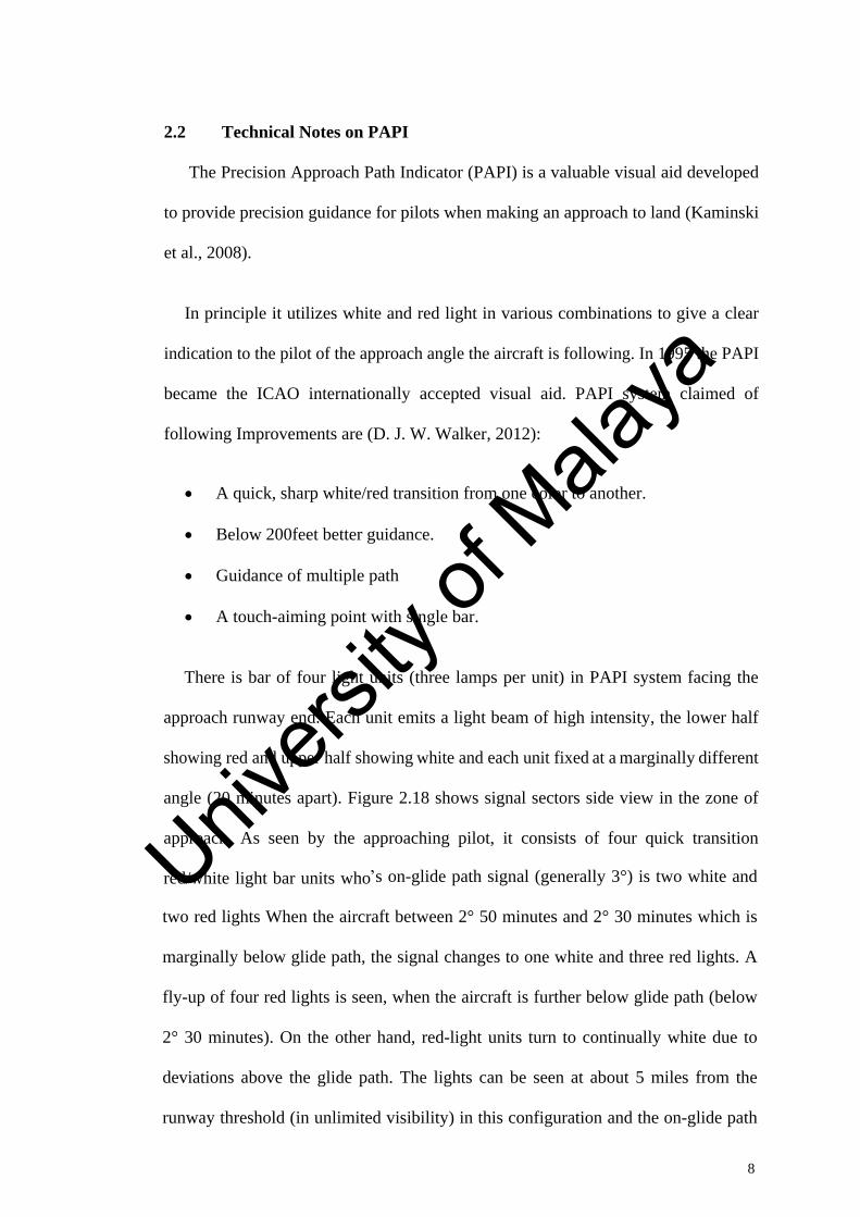
2.2 Technical Notes on PAPI
The Precision Approach Path Indicator (PAPI) is a valuable visual aid developed
to provide precision guidance for pilots when making an approach to land (Kaminski
et al., 2008).
In principle it utilizes white and red light in various combinations to give a clear
indication to the pilot of the approach angle the aircraft is following. In 1995 the PAPI
became the ICAO internationally accepted visual aid. PAPI system claimed of
following Improvements are (D. J. W. Walker, 2012):
A quick, sharp white/red transition from one color to another.
Below 200feet better guidance.
Guidance of multiple path
A touch-aiming point with single bar.
There is bar of four light units (three lamps per unit) in PAPI system facing the
approach runway end. Each unit emits a light beam of high intensity, the lower half
showing red and upper half showing white and each unit fixed at a marginally different
angle (20 minutes apart). Figure 2.18 shows signal sectors side view in the zone of
approach. As seen by the approaching pilot, it consists of four quick transition
red/white light bar units who s on-glide path signal (generally 3°) is two white and
two red lights When the aircraft between 2° 50 minutes and 2° 30 minutes which is
marginally below glide path, the signal changes to one white and three red lights. A
fly-up of four red lights is seen, when the aircraft is further below glide path (below
2° 30 minutes). On the other hand, red-light units turn to continually white due to
deviations above the glide path. The lights can be seen at about 5 miles from the
runway threshold (in unlimited visibility) in this configuration and the on-glide path
Univers
ity of
Mala
ya

9
depth of signal progressively decreases to approximately 6 feet at the threshold (Tian
& Tian, 2013).
Figure 2. 1 PAPI approach path (side view)
Figure 2. 2 Approach Path Illustration
Univers
ity of
Mala
ya

10
The Precision Approach Path Indicator (PAPI) is a 4 light units block located
beside landing runways, that provides visual guidance information to pilots for
acquiring and maintaining a safe and accurate glide slope on final approach. Placed
perpendicular to the runway approach path, generally on the left side, each PAPI unit
fits a row of lights emitting red light below a certain angle, and white light over. This
instrument can have an effective visual range up to 3 miles during the day and up to
20 miles at night.
While landing, pilots can determine if their approach is too high, too low or on the
correct slope, thanks to the red and white indicators. For a correct approach, the pilot
must observe 2 red and 2 white lights as follow. From 3 white lights and more, it
indicates that the aircraft is too high. On the other hand, 3 red lights and more indicates
that the aircraft approach is dangerously too low. To maintain operational conditions
and precision of the system, projected maintenance is carried-on using for instance
flying machines or elevating work platforms. Blocking off the access to the runway,
PAPIs checking is made by simulating sinusoidal approaches to verify threshold
angles and ensure compliance with regulations. On the down side, the airport
necessarily shuts down the runway, consuming up-time, imposing complicated
Figure 2. 3 PAPI light units block visual guidance
Univers
ity of
Mala
ya

11
logistics and taking risks by deploying operators in the air and on the runways (Castle,
1983).
2.3 Back ground of PAPI
Since precision landings have been required, there have been several devices used
to assist pilots when making an approach to land. They ranged from single light units
that incorporated a motor to drive a disc housing colored filters, to the more commonly
used 2 Bar and 3 Bar VASI or AVASI. There are other systems still in use (e.g.
Australia) such as the T-VASIS and ATVASIS. To improve approach slope guidance,
developers and designers of visual aids increased the numbers of light units
dramatically. The result was to add a greater element of confusion in to the equation.
The old systems where constructed around, SIMPLICITY INCREASES
RELIABILITY, so developing a system that basically only uses 4 light units was a
change for the better (Castle, 1983).
2.4 The Requirement
The PAPI system is normally a single wing bar consisting of 4 light units situated
on the left side of the runway. However, it is acceptable to locate the PAPI on the right
side if local conditions prevent it being located on the port side. In addition, many
airports adopt to have two PAPI Wing-Bars. This configuration is referred to as bi-
lateral and consists of port and starboard wing bars that employ a total of 8 light units
for each runway touchdown zone. A full bi-lateral system would generally be
employed on the larger airports providing the runway/taxiway layout places no
restrictions on its use (Smith & Johnson, 1976).
Univers
ity of
Mala
ya

12
Figure 2. 4 Typical unit of PAPI
2.5 Settings angles
1. The typical settings angles for a 3° glide slope are 2°30 (unit A); 2°50 (unit
B); 3°10 (unit C) and 3°30 : it means a sector of 20 difference between each
unit.
2. The on-course sector of 20 can vary according the presence of an instrument
landing system (ILS) (2°25 ; 2°45 ; 3°15 & 3°35 )
3. If double wing : symmetric transition at the same moment
4. A-PAPI: setting angles of 2°45 and 3°15
5. If double wing: symmetric transition at the same moment
a
Univers
ity of
Mala
ya

13
b
Figure 2. 5 Setting (a) Angles of PAPI and (b) A-PAPI
Univers
ity of
Mala
ya

14
2.6 Obstacle Clearance Surface
To guarantee the obstacle clearance for an aircraft approaching the runway
guided by a PAPI system, the OCS is established and measure it is clear up
to 15 kilometers.
This OCS is an inclined plane surface starting from the runway before the
PAPI unit. The slope of the OCS surface is 0.57° lower than the setting
angle of the lowest PAPI
Its horizontal projection is also defined
The angle of elevation settings of the light units in a PAPI wing bar shall
be such that, during approach, the pilot of an aero plane observing a signal
of one white and three reds will clear all objects in the approach area by a
safe margin.
If the units show red in color, the pilot knows he is dangerously below the
glide slope and possibly even below the obstacle clearance surface (OCS)
(Millar, 1984).
Figure 2. 6 Shows Pilot Approach Slightly Low
Figure 2. 7 View of obstacle clearance surface
Univers
ity of
Mala
ya

15
2.7 Design of the PAPI unit
Each PAPI unit divides the light output into two main sectors. The area that divides
the white and red light is known as the Transition Sector. In this area, pink light is
produced as a result of white and red light overlapping which create pink in between.
Manufacturers have design limits that do not exceed ICAO Annex 14
recommendations, namely:
A maximum of 3 minutes of arc are all that are allowed for the transition
sector.
The modern method for those companies using credible design and good lens
optics, is to have a double lens configuration to reduce the pink zone.
Many pilots today complain that the PAPI units are pink looking after a period.
Unfortunately, when this is the case it is either:
The deterioration in the quality of the lens
Or the unit is constructed using one lens assembly only.
Whilst these units under aircrew complaint are compliant at manufacture and
installation, deterioration soon occurs resulting in the pink complaint from the
aircrew. When this is the situation, we can only assume that the airport has purchased
units from less reputable suppliers
2.8 Transition Sector
PAPI unit: light signal, lower half: red, upper half: white.
The transition from one color to another one in a vertical plane have to be
virtually instantaneous => impossible
Univers
ity of
Mala
ya

16
The color transition from red to white in the vertical plane shall be such as
to appear to an observer, at a distance of at least 300m, to occur within a
vertical angle of not more than 3 ,
Transition sector lower than 3 arc in depth and 8° horizontally on both
sides of the beam s center, with a maximum expansion of 5 arc in depth
and 8° horizontally on both edges of the beam.
Figure 2. 8 Internal view of PAPI Unit
Thanks to the use of the two lenses in tandem, the producer reaches a
transition sector which does not exceed 3 arc through the whole horizontal
width of the beam.
Only one lens: big distortion of the projected image.
The following diagram shows the light output from a reputable supplier:
Univers
ity of
Mala
ya

17
The transition sector is essential and must be as small as possible.
Example: only one lens: transition sector of 10 on the beam s edges
(optical distortion) => operational area: only 10 => very difficult for the
pilot.
Figure 2. 9 Characteristics of the light unit's Transition Sector Sharpness
Figure 2. 10 Shows Transition Area
Univers
ity of
Mala
ya

18
Figure 2. 11 Typical PAPI Component Layout
2.9 Typical PAPI Construction
Different components of a typical PAPI used in the construction PAPI unit are
listed below as shown in figure 2.29.
1. Cover
2. Front glass
3. Front glass gasket
4. Outer lens + clamping ring
5. Inner lens + clamping ring
6. Red filter
7. Filter retainer
8. a. Refocus cold mirror
halogen lamp (3)
8. b. Fixing holding spring
9. Terminal block with cut-out
10. Heat resistant wire
11. Cover gasket
12. Lockable latch
13. Aluminum alloy housing
14. Compression bushing)
15. 2-core cable with 2-pole plug
16. Upper flange
17. Levelling plate
18. Lower flange
19. Mounting leg with frangible
groove
20. Ground mounting flange
21. Anchor bolts (6) (optional)
Univers
ity of
Mala
ya

19
Figure 2. 12 Exploded view of PAPI
Univers
ity of
Mala
ya

20
2.10 Light beams and angle of elevation setting of PAPI
Figure 2. 13 Pilots View of PAPI Installation Depending on Approach Slope
Univers
ity of
Mala
ya
21
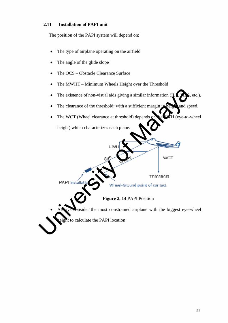
2.11 Installation of PAPI unit
The position of the PAPI system will depend on:
The type of airplane operating on the airfield
The angle of the glide slope
The OCS
Obstacle Clearance Surface
The MWHT
Minimum Wheels Height over the Threshold
The existence of non-visual aids giving a similar information (ILS, MLS, etc.).
The clearance of the threshold: with a sufficient margin in height and speed.
The WCT (Wheel clearance at threshold) depends on the EWH (eye-to-wheel
height) which characterizes each plane.
Always consider the most constrained airplane with the biggest eye-wheel
height to calculate the PAPI location
Figure 2. 14 PAPI Position
Univers
ity of
Mala
ya

22
Figure 2. 15 Calculation of PAPI Location with Biggest Eye-Wheel Height
To determine the installation in relation to the threshold we first have to know the
reference plane. This choice determines the EWH (Eye-Wheel Height) parameter and
consequently the TCM (Threshold Clearance Margin) characteristic given below in
the following table:
Table 2. 1 Characteristics of EWH and TCM
EHW Desire TCM Minimal TCM
< 3m 6m 3m (1)
3m et < 5m 9m 4m
5m et < 8m 9m 5m
8m et < 14m 9m 6m
Univers
ity of
Mala
ya

23
In exceptional cases this margin can be reduced to 1.5m if the runway is
only used by light planes other than turbojet planes.
The PAPI installation will not be done on the same location depending on
whether the airfield is equipped with an ILS (Instrumental Landing System)
or not.
Figure 2. 16 Theoretical Positioning of the PAPI to Assure an Appropriate Threshold Clearance Margin
2.11.1 Verification of the interferences with Obstacle Clearance Surface (OCS)
Lower edge: at 60 m of the threshold, width depends on the number code of
the runway
OCS = 1 - 0.57°
1: adjustment of the PAPI-A unit
If the approach slope is of 3° The OCS slope will be: = 2° 30 - 0.57°= 1°56
Univers
ity of
Mala
ya

24
If an obstacle interferes with the OCS, it will be necessary:
A) To displace or to remove the obstacle (if it is feasible)
B) To displace the threshold
C) To displace the PAPI in such a way the threshold clearance margin is increased
by a height equal to the interference height of the obstacle
D) As a last resort, the approach slope shall be increased until the obstacle is no
more in the OCS.
The calculation of PAPI s position is done based on the hypothesis that the units
are at the same level as the runway axis adjacent to their position, which would be the
same as the one of the threshold. If it is not the case, some additional calculations shall
be done in order to iron out the topographical differences.
Figure 2. 17 Verification of the interferences with Obstacle Clearance Surface
Univers
ity of
Mala
ya

25
2.11.2 Installation of a PAPI with an ILS: Harmonization between the PAPI
and ILS
There is one point since where the pilot is out of the PAPI s approach way but
still in the one of the ILS
This point depends on the Eye-Antenna height (EAH)
The influence of the ILS might extend the run
until 30 for some kinds of devices (>< 20 normally).
2.11.3 Calculation for the Positioning of a PAPI on a Runway Equipped with
an ILS
2.11.4 Verification of wheel clearance height
A) EWH B737: 5.18m
TCM Minimum TCM (Threshold clearance margin)
B737 9m 6m
If MEHT of 15m, 15-5,18= 9.82m > 9m => OK.
Figure 2. 18 Installation of a PAPI with an ILS
Univers
ity of
Mala
ya

26
2.11.5 Correction of the PAPI Position Depending on the Topographical
Variation
The critical data during the modification of PAPI s position is the METH.
For a difference of threshold level of -3.14m, it is necessary to move the
position of the PAPI of 3.14 x cotg 2°43 = 66.33 m towards the threshold
PAPI s amended position is of 252.27 m from the threshold.
If at this place the ground level is not the same as the originally calculated
position of 318.6m, we must recalculate again the new topographical data.
Figure 2. 19 Correction of the PAPI position depending on the topographical variation
Univers
ity of
Mala
ya

27
2.11.6 Verification of the Ground Level:
Ground height at 318.6 m: 63.79 m
Ground height at 252.27 m: 63.08 m
Difference: - 0.71m
PAPI has to be moved of 0.71 x cotg 2°43 = 14.96m away
from the threshold
New position for the PAPI: 252.27 + 14.96 = 267.3 m
Double-checking of the ground height in the new position:
Ground height at 267.23 m: 63.31 m
Ground height at 252.27 m: 63.08 m
Difference: 0.23m
Difference lower than 0.3m => no more iteration needed
2.11.7 Correction of the PAPI Position Depending on the Lens Height
Let us say that the lens center is 30 cm high from the ground:
=> Move the PAPI closer of the threshold: 0.3 x cotg 2°43 = 6.32 m
=> Final position of the PAPI: 267.27 - 6.32 = 260.91 m or 261m
. Double-checking of the MEHT against coarse errors
MEHT: 261 x tan 2°43 + (63.21 - 60.65) + 0.3
12.37 + 2.56 + 0.3 = 15.23 m
This value is > 15m => OK
Univers
ity of
Mala
ya

28
2.11.8 Compensation of the Transversal Slope of the Runway
The transversal slopes exist on all the runways and have to be taking into
account in the positioning calculation of the PAPI s. All the levels have to
make reference to one datum: the height of the runway axis.
A topographical study has to be carried out from one side to the other side of
the runway at the place where the PAPI s have to be installed.
Sometimes when the transversal slope of the runway is important, it is
necessary to align the PAPI s on a leaning axis perpendicular to the runway,
so that it corresponds to the limit height of the bases of the four aligned units.
According to the field, the whole group of PAPI units might not be placed on
a straight line, perpendicular to the runway (Smith & Johnson, 1976).
Univers
ity of
Mala
ya

29
Figure 2. 20 Connection of PAPI Unit
Figure 2. 21 Dimensions of the Typical PAPI Univ
ersity
of M
alaya

30
CHAPTER 3: METHODOLOGY
3.1 Introduction
In this chapter, methodology on designing and simulating the PAPI is discussed.
This chapter start with explanation on the flow diagram of this research. Next,
parameters of stepper motor are defined. Then, analysis the performance of stepper
motor. Lastly, showing the simulation result using AutoCAD SOLIDWORKS.
Univers
ity of
Mala
ya

31
3.2 The Flow Diagram of Study
Yes
No
Figure 3. 1 Flow chart for stepper motors for application of PAPI
Design of Lead Screw Stepper Motor
Design of Precision Approach Path Indicator
Start
Design and Specification of Stepper Motor and PAPI system
Design of PAPI system and Lead Screw Stepper
Motor by using AutoCAD SOLIDWORKS
Simulation of Ladder Diagram by using CX-Programmer Software
Optimize the parameters
Analyse the Stepper Motor and PAPI
performance
Result analysis and discussion
End
Univers
ity of
Mala
ya

32
This research begins with reading all the literature material on electrical machines,
special purpose motors, stepper motors, types of stepper motor, working principle of
each stepper motor, advantages and disadvantages of stepper motor and applications
of stepper motor in industry peripherals, solar array tracking system, motion control
and robotics, business machine, which are included in machine tool and process
control applications. In addition, the type of PAPI, the siting locations and angle
information are all gathered. Going through literature review process will give brief
ideas on how and what this project will be doing. All the related theory and useful
formula for stepper motor such as step angle is collected during the literature review.
From all the information gathered in literature review stage, PAPI and stepper
motor design specification are determined. Stepper motor will be installed underneath
the PAPI front area for the control of the angle of the PAPI lights. The PLC will be
installed inside the PAPI to control the elevation angle and the push button to control
up and down will be installed on the side out of PAPI. Then from the design specs,
PAPI with stepper motor is modelled using AutoCAD SOLIDWORKS software.
Based on flow chart shown in figure. Important steps to simulate the model in
SOLIDWORKs are begin with building the PAPI with the integration of the stepper
motor
To analyze the stepper motor behavior and performance, a design of stepper motor
is simulated. Results from the simulation is obtained and proceed with the analysis
stage. Next discussion is made based on the result obtained. Finally, a conclusion is
made referring to the project outcome and research project recommendation or future
improvement is proposed.
Univers
ity of
Mala
ya

33
3.3 Design and Specification of Stepper Motor and PAPI System
In this project, we are going to use Nema 42 stepper motor for controlling of PAPI
system in airfield ground lighting. Design of stepper motor is shown in Figure 3.1 and
a following specification of stepper motor is given in following Table 3.1 below.
Figure 3. 2 Design of Nema 42 Stepper motor
Table 3. 1 Physical Specification of Nema 42 Stepper Motor
specifications value
Model 42HS59-6004S
Body length 150mm
Shaft diameter 19mm
Key way length 35mm
Shaft length 55.37mm
Number of leads 4
Lead length 500mm
Weight 10.9kg
Frame size 110 * 110mm
Univers
ity of
Mala
ya

34
Above Table 3.2 shows physical specification of stepper motor such model of
motor is 42HS59-6004S, body length of 150mm, weight of motor 10.9kg, number of
leads is 4 and some more. Physical specification shows that stepper motor suitable to
handle the load of PAPI system and perform a operation nicely.
Table 3. 2 Electrical Specification of Nema 42 Stepper Motor
Connection
Specification
Bipolar
VOLTAGE (VOC) 4.80
AMPS/PHASE 6.00
RESISTANCE/PHASE (Ohms) at 25 C 0.80
10%
INDUCTANCE/PHASE (mH) at 1 KHz 14.00
20%
HOLDING TORQUE (Priya & Inman)(lb
ln) 22.00 (194.72)
STEP ANGLE 1.80
STEP ACCURACY (NON-ACCUM) 5.00%
ROTOR INERTIA (g- ) 13000.00
Motor type Bipolar stepper
Above Table 3.2 shows an electrical specification of Nema 42 stepper motor that
type of motor is Bipolar type can operate in both directions and having a step angle of
1.8 . Therefore, some of specification of stepper motor not mentioned in above Table
3.2, such as stepper motor Temperature Rise: Max 80 C (Motor standstill; for 2 phase
energized), Ambient Temperature -10 C-50 C (14 F-122 F), Insulation Resistance
under normal temperature and humidity is 100Mohm, insulation class B 130 C
Univers
ity of
Mala
ya

35
(266 F), between the motor coils and the motor case the Dielectric strength of motor
for 1min is 500VAC and Ambient humidity Max 85% (no consideration). Figure 3.2
is given below, shows the external connection type of stepper motor.
Figure 3. 3 Shows a Stepper motor external connection type
3.4 Design of PAPI system and Lead Screw Stepper Motor by using
AutoCAD SOLIDWORKS
Based on project, Design of PAPI system stepper motor with Lead Screw is design
on SOLIDWORKS software. Following Figure given below shown a design of PAPI
system and Lead Screw stepper motor.
Figure 3. 4 Lead Screw Stepper Motor
Univers
ity of
Mala
ya

36
Above figure 3.3 shows a lead screw stepper motor design on SOLIDWORKS
software. Lead screw stepper motor consist of small gear, big gear and screw. Rotation
of stepper motor small gear helps to rotate the big gear of stepper motor relatively
screw will also move up and down. Lead screw movement results the up and down
movement of PAPI system. Stepper motor attached on front pole of PAPI system
because back end of PAPI system is fixed and front end is movable. Specification of
stepper Motor is shown in Table 3.3 below.
Table 3. 3 Specification of Lead screw of Stepper Motor
Items Specifications Screw pitch 0.5mm
Diameter of screw 10mm
Length of screw 90mm
Ratio big to small gear 1:2
From the above Table 3.2 we know that weight of complete PAPI System is 10Kg.
Based on PAPI system we design a stepper motor in SOLIDWORKS software with
lead screw with a diameter of screw is 10mm and length of screw 100mm which is
suitable to carry the load of PAPI system and easily handle the rise and down
movement of PAPI system and pitch of screw is 0.5mm. we assume the ratio between
the big gear of motor to the small gear of motor is 1:2 means 2 revolution of small
gear equal to one revolution of big gear. Big gear is used to support a screw up and
down movement.
In addition, we selected 90 mm of length which is sufficient to cope for the
maximum angle of the PAPI system.
Univers
ity of
Mala
ya

37
Figure 3. 5 Top assembly of PAPI System with push button and indicator to control raise and lower the elevation
Figure 3. 6 Bottom assembly of PAPI leg to mount on site
Univers
ity of
Mala
ya

38
Figure 3. 7 Final assembly of PAPI with two legs
Above figure 3.7 is the picture of complete assembly of PAPI with stepper motor.
The stepper motor is installed underneath of the top assemble PAPI front side in the
middle. With the hinge mount at the back between top and bottom assemble to
permanently fix the PAPI. By fix at the back of the PAPI thus the angle of the light
beam can be created when the stepper motor raise or lower on the front PAPI. We
designed also the push button and the indicator for the maintenance team to press and
select of 4 setting angles require. The left button is for raise, second button for the
lower and third button reserve for future use. The maintenance team also can see the
display of the digital inclinometer to confirm the angle is correct.
Univers
ity of
Mala
ya

39
PAPI A 2.50°@ 2°30'
PAPI B 2.83°@ 2°50'
PAPI C 3.17°@ 3°10'
PAPI D 3.50°@ 3°30'
3.5 Design of Leadscrew Stepper Motor
First design of Leadscrew stepper motor which would be integrated on PAPI
system and design begins by defining the parameters of leadscrew stepper motor.
Table 3. 4 Parameters of Lead Screw Stepper Motor
Parameter Value Unit
Body Length 150 mm
Shaft Diameter 19 mm
Key Way Length 35 mm
Shaft Length 55.37 mm
Lead Length 500 mm
Frame Size 110 * 110 mm
Screw Pitch 0.5 mm
Diameter of Screw 10 mm
Length of Screw 90 mm
Big gear and small gear diameter
30/15.12 mm
Univers
ity of
Mala
ya

40
Figure 3. 8 Design of Leadscrew Stepper Motor
Figure 3. 9 Top-View of Leadscrew Stepper Motor
Univers
ity of
Mala
ya

41
Figure 3.8 shows the Leadscrew stepper motor which is designed by using
AutoCAD SOLIDWORKS software. The motor design with leadscrew because
leadscrew support and help in up and down movement of PAPI system. Diameter of
screw is 10mm suitable to hold the weight of PAPI and screw pitch is 0.5mm. when
big gear complete one revolution screw moves 0.5mm up or down depends on
adjustment of elevation angle of PAPI. Length of screw 90mm which is suitable to
cover the desired the angle of PAPI. Figure 3.9 shows top part of view which helps in
vertical movement of PAPI system. Big is used to support the lead screw and ratio
between big gear to small gear is 1:2 means that one revolution of big gear is equal to
two revolutions of small gear also can be consider two revolution of stepper motor
moves the 0.5mm vertically. Frame is size of motor is 110 * 110mm. Later, motor
should be integrated on suitable position underneath of PAPI. Other parameters which
is used in designing of PAPI is mentioned in above Table 3.4.
3.6 Design of Precision Approach Path Indicator
In second case, design of Precision Approach Path Indicator system begins by
defining the parameters of PAPI system.
Table 3. 5 Parameters of PAPI System
Parameter Value unit
Weight of PAPI top assembly 10.2 kg
PAPI top assembly length 830 mm
PAPI top assembly hinges to stepper motor
614.4 mm
PAPI top assembly width 290 mm
Height top assembly 256.36 mm
PAPI bottom assembly length 690 mm
PAPI bottom assembly width 290 mm
Univers
ity of
Mala
ya

42
Figure 3. 10 Design of Bottom Assembly of PAPI System
Univers
ity of
Mala
ya

43
Figure 3. 11
Design of Top Assembly of PAPI System
Figure 3. 12 Complete Assembly Design of PAPI System with Leadscrew Stepper Motor
Univers
ity of
Mala
ya

44
Figure 3. 13 Back
View of PAPI System
Figure 3. 14 Lead Screw Stepper Motor with Support thread
Univers
ity of
Mala
ya

45
Figure 3. 15 Side-View of PAPI System
Figure 3.10 shows the bottom assembly of PAPI system. Bottom assembly of PAPI
fixed at ground and can say supporting legs for top assembly of PAPI. However please
note that the bottom assembly height can cut during installation to set the same height
at the center of the light to the Threshold light height. So here the distance x will be
the similar height and the setting angle of PAPI is 3 degree. Thus, the consultant or
design Engineer is able to determine the plane type during design the airport. Top
assembly of PAPI system is shown in Figure 3.11. Red and blue button on top
assembly indicates the push button and digital meter of PAPI system. Figure 3.12
shows the complete assembly of PAPI system with leadscrew stepper motor which is
integrated underneath of top assembly of PAPI. Leadscrew stepper motor at front
below the top assembly which is movable of part of PAPI and another end of PAPI is
fixed. Complete PAPI assembly is designed by using the software AutoCAD
SOLIDWORKS software. PAPI bottom assembly length is 690mm and PAPI bottom
assembly width is 290mm and other parameters of top and bottom assembly is
mentioned above in Table 3.5. Therefore Figure 3.14 shows the support leadscrew
Univers
ity of
Mala
ya

46
stepper motor integrated beneath the top assembly and shows the support thread which
is used to support the movement of leadscrew and make the movement of screw
smoothly. Figure 3.13 and 3.15 shows the back and side view of PAPI system. Figure
4.8 clearly shows that leadscrew stepper motor help to move the top assembly of PAPI
system vertically by help of leadscrew one revolution moves the screw vertically
0.5mm and with the help of leadscrew stepper motor can adjust the elevation angle of
PAPI automatically. And the stepper motor is fixed with the thread on the bottom
assembly at below and top thus it will fix the leadscrew in one position to ensure the
smooth of raise or lower of the PAPI. In addition, it will hold and maintain the position
of the stepper motor, small and big gear.
3.7 Simulation of Ladder Diagram by Using CX
Programmer Software
Simulation of ladder diagram of PAPI system with timer is performed by using a
CX programmer software and shown below.
Univers
ity of
Mala
ya

47
Figure 3. 16 Ladder Diagram of PAPI system
Figure 3.16 shows the ladder diagram of PAPI system by using CX - Programmer.
There are four units of PAPI with different elevation angle. PAPI A with elevation
angle of 2.50°, PAPI B is 2.83°, PAPI C elevation angle is 3.16° and PAPI D with
elevation angle of 3.50°. There is also reset switch for resetting of operation and turn
back the PAPI leadscrew to 0°original position. All PAPI s connected separately with
their respective timer. Function of timer is that to run motor specific period then OFF,
and it will maintain to that position. When any of PAPI is not at proper elevation angle
then need to adjust the elevation angle of PAPI by pressing the push button which
results in turn on stepper motor with leadscrew for specific period until elevation angle
is covered then OFF a motor. for example, to adjust the elevation angle of PAPI A
motor should be ON for 1.5s.
Univers
ity of
Mala
ya

48
3.8 Summary
This chapter discussed on the methodology approach for this research project.
Beginning of this chapter explained the flow chart of the methodology that has been
used. Followed by defining the design and structure parameters of stepper motor and
PAPI system based on project requirements. Next, the stepper motor design parameter
and the varied parameter is chosen for PAPI application. All the design is realized
using AutoCAD SOLIDWORKS software. Finally, Simulation of Ladder Diagram by
using CX-Programmer Software.
Univers
ity of
Mala
ya

49
CHAPTER 4: RESULT AND DISCUSSION
4.1 Calculation of PAPI System and Lead Screw Stepper Motor for PLC
Following formula given below is used to calculate the Steps per revolution
Steps per Revolution = 360 / Step Angle 4.1
Revolution per Second can be calculating by using equation given below.
Revolution per Second = V/(L*2*Imax)/(steps/rev) 4.2
Vertical movement of PAPI system can be calculate by using equation given below.
Tangent = Y/X 4.3
Calculated values of PAPI system given below in Table 4.1
Table 4. 1 Calculated value of PAPI and leadscrew stepper motor
PAPI
System
Elevation
Angle
Screw
Pitch
Steps per
Revolution
Vertical
Movement
of PAPI
Revolution
per
Second
Calculate
PLC
Timer
in sec
Percentage
%
PAPI
A 2.5
0.5mm
200 26.825mm 1.53 1.50 1.98
PAPI
B 2.83
0.5mm
200 30.371mm 1.73 1.70 1.74
PAPI
C 3.16
0.5mm
200 33.92mm 1.94 1.90 2.00
PAPI
D 3.5
0.5mm
200 37.57mm 2.14 2.10 1.88
Univers
ity of
Mala
ya

50
Based on table 4.1, We know 1 revolution of the big gear will result in 1 rotation
of the screw and vertical movement of 0.5 mm This is equal to 2 rev of the small gear
(since N = 2), and hence 2 rev of the motor So, 1 rev of the motor will cause the screw
to move only half pitch, i.e. 0.25mm since 1 rev is equals to 200 steps, 1 step will give
0.25mm/200 = 0.0125 mm vertical movement and make it easy to determine the
number of steps required for different vertical movements of the screws. Therefore,
when we get know the vertical movement of screw then in result can calculate the
revolution per second of leadscrew stepper for each PAPI unit to cover the desired
elevation angle.
Univers
ity of
Mala
ya

51
4.2 Simulation of the PLC Automation for PAPI A at 2.5
Figure 4. 1 PAPI A at 2.5
Above Figure 4.1 shows the simulation of ladder diagram for PAPI A. During
installation of the PAPI, the installer just pressed one-time push button and the
elevation angle of PAPI A will be set. The timer and motor will be turn ON at same
time. Motor will run for 1.5 seconds to cover the angle of 2.50° then it will be OFF.
First rung of ladder diagram shows the simulation of PAPI A and rung 6 represent the
function of timer and green line at both one and six rung represents a timer and motor
is performing a function to adjust the angle of PAPI A. Figure 4.2 shows that a timing
diagram of PAPI A.
Univers
ity of
Mala
ya

52
Figure 4. 2 Timing Diagram of PAPI A
Univers
ity of
Mala
ya

53
4.3 Simulation of the PLC Automation for PAPI B at 2.83
Figure 4. 3 PAPI B at 2.83
Simulation for PAPI B is shown in Figure 4.3. During installation of PAPI B, press
the push button for the first time, and when it will stop at 2.50°, and press again the
push button for the second time and the second timer will add on another 0.2 seconds
which will cover PAPI B position which is 2.83°. It will automatically align the
position of PAPI B by help of leadscrew stepper motor. Figure 4.3 shows that rung 2
green line in ladder diagram shows the function of motor and rung 7 green line
represent the timer function and for alignment of elevation angle of PAPI motor will
run approximately 1.7 seconds because motor will cover 2.83
in 1.7 seconds.
Univers
ity of
Mala
ya

54
Figure 4.4 shows the timing diagram of PAPI B and it indicates that lead screw stepper
motor is ON for 1.7 seconds to align back the elevation angle of PAPI B. All other
PAPI s OFF while aligned the PAPI B.
4.4 Simulation of the PLC Automation for PAPI C at 3.16
Above Figure 4.3 shows the simulation result of PAPI C. Accurate elevation angle
of PAPI C is 3.16°. To set PAPI C, we will need to press the push button for 3 times.
Means 1.5 second plus 0.2 seconds and plus another 0.2 seconds will be in total 1.9
seconds to cover 3.16°. Figure 4.3 shows that rung 3 and rung 8 with green line marked
shows the simulation result of PAPI C.
Figure 4. 4 Timing Diagram of PAPI B
Univers
ity of
Mala
ya

55
Figure 4. 5 PAPI C at 3.16°
Timing diagram of PAPI C is shown below in Figure 4.6. Timing diagram indicated
to adjust the elevation angle of PAPI back to 3.16
lead screw motor need to turn ON
for a time of 1.9s. After 1.9s PAPI C aligned back to its original position. Univers
ity of
Mala
ya

56
4.5 Simulation of the PLC Automation for PAPI D at 3.5
Figure 4. 7 PAPI D at 3.5
Figure 4. 6 Timing Diagram of PAPI C
Univers
ity of
Mala
ya

57
Simulation result of PAPI is shown in Figure 4.7. Green line marked on rung 4 and
rung 9 shows the simulation result of PAPI D and timer. In this position, we need to
push the button four times means 1.5s plus 0.2s plus 0.2s plus 0.2s which in total 2.1s.
To adjust the elevation angle of PAPI D motor need run for 2.1 seconds and motor
will cover elevation angle of 3.5 in this period.
Timing diagram of PAPI D is shown below in Figure 4.8. Timing diagram
indicated to adjust the elevation angle of PAPI back to 3.5
lead screw motor need to
turn ON for a time of 2.1s. After 2.1s PAPI D aligned back to its original position.
Figure 4. 8 Timing Diagram of PAPI D
Univers
ity of
Mala
ya

58
4.6 Simulation of the PLC Automation for PAPI System Reset
Figure 4. 9 PAPI System Reset
Figure 4.9 shows the simulation result of resetting of PAPI system. Green line marked
on rung 5 and rung 10 shows resetting of PAPI system. To reset the PAPI back to
original position. Press additional one-time push button after PAPI D. Means 5 times
to press the push button. Figure 4.10 shows that a timing diagram for reset of PAPI
system. Timing diagram indicated that Reset of system take time of 2.1s after PAPI D
is aligned.
Univers
ity of
Mala
ya

59
Figure 4. 10 Timing Diagram for Reset of PAPI System
Univers
ity of
Mala
ya

60
CHAPTER 5: CONCLUSION AND RECOMMENDATION
5.1 Conclusion
Based on this project, first we successfully designed the PAPI and Leadscrew
stepper by using the AutoCAD SOLIDWORKS software. Leadscrew stepper motor
integrated on PAPI unit. Stepper motor beneath the top assembly of PAPI unit at front
side which is a movable part of PAPI. Leadscrew is used in stepper motor and position
of leadscrew below the movable part of PAPI and move the PAPI unit vertically up
and down for adjustment of elevation angle. Secondly, we performed the simulation
of each PAPI unit and leadscrew stepper by using the CX programmer software. timer
is used in simulation which helps to run a motor for a specific until a desired angle is
covered. From the results obtained, it shows that by integrated stepper motor and timer
on PAPI helps in automatically adjustment of elevation angle of each PAPI unit and
reduce time consuming, cost reduction, no need of special tools and extra manpower
to communicate with aircraft calibration and to adjust the angle using tool and manual.
However, due to the timer in CX Programmer only can set at 0.1 sec the smallest unit,
therefore it resulted a small tolerance if compare to the calculation angle. Following
table is showed the tolerance which reflect to the calculation angle due to the timer
that used.
Univers
ity of
Mala
ya

61
Table 4. 2 Calculated value of PAPI and leadscrew stepper motor
The maximum tolerance effect on PAPI D which is 0.07°@4'. From the table,
found the tolerance is very small compare to between PAPI with 0.33°@20'.
5.2 Recommendation
This research has successfully designed and simulated, however, use of
microcontroller instead of PLC is more accurate operation as it can control the number of
steps which covers 0.0125 mm height each steps. While with timer it only can cover 0.1
sec the smallest settings. In addition with microcontroller we can design a closed loop
system with feedback digital indicator to confirm the angle.
In this project only, vertical movement of PAPI unit controlled. In future research
horizontal movement of PAPI unit can be considered for the idea to level the PAPI. In
addition, the Leadscrew stepper motor is designed by using AutoCAD SOLIDWORKS
software and simulation performed on CX programmer. In future, this designed can
be make practically and check PLC programming for the real operation of leadscrew
stepper for adjustment of elevation angle of PAPI system.
PAPI
System
Elevation
Angle
Vertical
Movement
Calculation
Revolution
per Second
Calculation
PLC
timer
in
sec
Elevation
angle
result Tolerance
PAPI
A 2.5° 26.82mm 1.53 1.50 2.46° 0.04°
PAPI
B 2.83° 30.37mm 1.73 1.70 2.78° 0.05°
PAPI
C 3.16° 33.92mm 1.94 1.90 3.11° 0.05°
PAPI
D 3.5° 37.57mm 2.14 2.10 3.43° 0.07°
Univers
ity of
Mala
ya

62
Table 5. 1 Calculated value of PAPI and lead screw stepper motor
Above Table 5.1 indicated the calculated value of PAPI and leadscrew stepper
motor. Vertical movement of PAPI is 26.825mm to adjust the elevation angle of PAPI
A and for that vertical movement the lead screw stepper motor required to move 2146
steps to cover the 26.825mm. PAPI B required vertical movement of 30.371mm to
back to its correct position and number of steps required for that vertical movement is
2429 steps. Number of steps required is 2713 steps to cover the vertical movement of
PAPI C is 33.92mm. For adjustment of elevation angle of PAPI C the PAPI required
vertical movement of 37.57mm for that vertical movement lead screw stepper motor
required 3005 steps.
Vertical movement of PAPI Number of steps required for vertical
movement 26.82mm 2146
30.37mm 2429
33.92mm 2713
37.57mm 3005
Univers
ity of
Mala
ya

63
REFERENCE
Bloudicek, R., & Luzica, S. (2015). Led light sources in the approach slope indicators and their visibility in inhomogeneous atmosphere. Paper presented at the Digital Avionics Systems Conference (DASC), 2015 IEEE/AIAA 34th.
Castle, B. (1983). Evaluation of Precision Approach Path Indicator (PAPI): FEDERAL AVIATION ADMINISTRATION TECHNICAL CENTER ATLANTIC CITY NJ.
Hubert, C. I. (1990). Electric machines: Prentice Hall.
Kaminski, M., Dubin, M. B., & Frate, M. (2008). Precision approach path indicator systems and light assemblies useful in same: Google Patents.
Liu, K., & Wang, C. (2018). Improved Optimal Route Evaluation Method for Wireless Sensor Networks. IEEE Sensors Journal, 18(4), 1747-1754.
Millar, J. (1984). An Analytical Comparison of Three Visual Approach Slope Indicators: VASIS, T-VASIS and PAPI: AERONAUTICAL RESEARCH LABS MELBOURNE (AUSTRALIA).
Nagod, S., & Halse, S. (2017). Evolution of MEMS Technology. Evolution, 4(12).
Oszust, M., Kapuscinski, T., Warchol, D., Wysocki, M., Rogalski, T., Pieniazek, J., . . . Rzucidlo, P. (2018). A vision-based method for supporting autonomous aircraft landing. Aircraft Engineering and Aerospace Technology, 90(6), 973-982.
Priya, S., & Inman, D. J. (2009). Energy harvesting technologies (Vol. 21): Springer.
Runyon, E. K., Williams, H. R., McCorkle, T. E., Weihs, M. E., & Williams, E. R. (1996). Airfield lighting system: Google Patents.
Slemon, G. R. (1992). Electric machines and drives: Addison-Wesley.
Smith, A., & Johnson, D. (1976). The Precision Approach Path Indicator-PAPI: ROYAL AIRCRAFT ESTABLISHMENT FARNBOROUGH (ENGLAND).
Tian, R., & Tian, Y. (2013). LED based precision approach path indicator: Google Patents.
Toliyat, H. A., Nandi, S., Choi, S., & Meshgin-Kelk, H. (2012). Electric machines: modeling, condition monitoring, and fault diagnosis: CRC press.
Walker, D. J., & Monaghan, A. (2015). Optical design of precision approach path indicators in a portable runway lighting system. Paper presented at the Optical Systems Design 2015: Illumination Optics IV.
Walker, D. J. W. (2012). PRECISION APPROACH PATH INDICATOR: US Patent App. 13/408,688.
Univers
ity of
Malaya