man ip800 v600 en instructions the manufacturer assumes no responsibility for any personal injury,...
TRANSCRIPT

P u r e I P T e l e p h o n y
IP gatewayIP800
AdministratorManual
Brand names are used with no guarantee that they may be freely employed. Almost all hardware and software designations in this manual are registered trademarks or should be treated as such.
All rights reserved. No part of this manual may be reproduced in any way (print, photocopy, microfilm or by any other means) or processed, duplicated or distributed using electronic systems without explicit approval.
Texts and illustrations have been compiled and software created with the utmost care, However errors cannot be completely ruled out. This documentation is therefore supplied under exclusion of any liability or warranty of suitability for specific purposes. innovaphone reserves the right to improve or modify this documentation without prior notice.
Copyright © 2001-2007 innovaphone® AG
IP gatewayIP800
ManualVersion 6.0
Release 6.0, 2nd edition, April 2007
PDF version available for download at: http://www.innovaphone.com
Copyright © 2001-2007 innovaphone® AG
Böblinger Str. 76 71065 Sindelfingen, Germany
Phone +49 (7031) 73009-0 | Fax +49 (7031) 73009-99
http://www.innovaphone.com
Safety instructionsThe manufacturer assumes no responsibility for any personal injury, damage to property or subsequent damage that can be attributed to improper use of the device.
Power supplyThe mains adapter of the device is designed for operation with a 100-240V, 50Hz AC network. Some devices can also be operated using PoE ( Power over Ethernet) in accordance with IEEE 802.3af. No attempt should ever be made to connect the equipment to other mains systems! In the event of power failure, the equipment settings are retained.
Installation and connectionThe connection cables should be laid safely so that no one can trip over them. Connected cables must not be bent excessively or subjected to mechanical strain.
The equipment is intended for use in dry rooms only.
• Operating temperature: 0° C to 40° C, 10% to 90% relative humidity, non-condensing.
• Storage temperature: -10° C to 70° C
The equipment must not be installed and operated under the following conditions:
• In damp, dusty, vibrating rooms or in rooms where an explosion may occur.
• At temperatures over 40°C or under 0°C
MalfunctionsThere is no need to open the device, if it is used as intended and serviced as specified. But if the device is opened for some reason, it must be ensured that all connection cables have been first removed. Before opening the device, interrupt the power supply by removing the power/Ethernet cable.
Do not open or reconnect faulty equipment. The original packing should be kept safely in case the device needs to be returned, since it provides ideal protection. All entries (for example, on a PC) should be backed up beforehand to avoid losing data.
DisposalWhen due for disposal, the device must be returned directly to the manufacturer innovaphone AG in accordance with the WEEE guidelines (Waste Electrical and Electronic Equipment). The costs for returning the device shall be borne by innovaphone AG.
Table of contents
Safety instructions ............................................................................... 4
Table of contents................................................................................. 5
1 Introduction .................................................................................... 10
1.1 Connection Option .................................................................. 10
1.2 Scalable in Both Directions ..................................................... 10
1.3 Two Ethernet Interfaces Guarantee Flexible Use ................... 10
1.4 Features .................................................................................. 10
2 Initial start-up................................................................................. 12
2.1 Establish administrator access................................................ 12
3 User interface.................................................................................. 14
3.1 Structure of the user interface................................................ 14
3.2 Protected areas ....................................................................... 15
3.3 Saving the settings ................................................................. 15
4 Configuration and administration ................................................... 16
4.1 Configuration .......................................................................... 16
4.1.1 Configuration/General .................................................... 16
4.1.1.1 Configuration/General/Info ............................................. 16
4.1.1.2 Configuration/General/Admin .......................................... 17
4.1.1.3 Configuration/General/Licence......................................... 17
4.1.1.4 Configuration/General/Update ......................................... 19
4.1.1.5 Configuration/General/NTP ............................................. 19
4.1.1.6 Configuration/General/HTTP Server ................................. 20
4.1.1.7 Configuration/General/HTTP Client .................................. 21
4.1.1.8 Configuration/General/Logging........................................ 21
4.1.1.9 Configuration/General/SNMP ........................................... 23
4.1.1.10 Configuration/General/Telnet......................................... 23
4.1.2 Configuration/IP............................................................. 23
4.1.2.1 Configuration/IP/Settings................................................ 24
4.1.2.2 Configuration/IP/NAT ..................................................... 25
4.1.2.3 Configuration/IP/H.323 NAT ........................................... 26
4.1.2.4 Configuration/IP/PPP Config ........................................... 26
4.1.2.5 Configuration/IP/PPP State ............................................. 31
4.1.2.6 Configuration/IP/Routing ................................................ 31
4.1.3 Configuration/ETH0-1.....................................................32
4.1.3.1 Configuration/ETH0-1/Link.............................................. 32
4.1.3.2 Configuration/ETH0-1/DHCP ........................................... 32
4.1.3.3 Configuration/ETH0-1/IP ................................................ 33
4.1.3.4 Configuration/ETH0-1/NAT ............................................. 34
4.1.3.5 Configuration/ETH0-1/VLAN............................................ 34
4.1.3.6 Configuration/ETH0-1/DHCP Server................................. 35
4.1.3.7 Configuration/ETH0-1/DHCP Leases ................................ 38
4.1.3.8 Configuration/ETH0-1/Statistics....................................... 39
4.1.4 Configuration/LDAP........................................................40
4.1.4.1 Configuration/LDAP/Server ............................................. 41
4.1.4.2 Configuration/LDAP/Server-Status ................................... 41
4.1.4.3 Configuration/LDAP/Replicator ........................................ 41
4.1.4.4 Configuration/LDAP/Replicator-Status.............................. 42
4.1.5 Configuration/TEL1-4 & PPP...........................................43
4.1.5.1 Configuration/TEL1-4 & PPP/Physical............................... 43
4.1.5.2 Configuration/TEL1-4 & PPP/Protocol .............................. 45
4.1.5.3 Configuration/TEL1-4 & PPP/Interop................................ 46
4.1.5.4 Configuration/TEL1-4 & PPP/State................................... 47
4.1.5.5 Configuration/TEL1-4 & PPP/Statistics ............................. 48
4.2 Administration........................................................................48
4.2.1 Administration/PBX ........................................................48
4.2.1.1 Administration/PBX/General ............................................ 49
4.2.1.2 Administration/PBX/Password ......................................... 51
4.2.1.3 Administration/PBX/Filter ................................................ 51

4.2.1.4 Administration/PBX/Objects............................................. 524.2.1.4.1 User Object:......................................................... 554.2.1.4.2 Boolean Object:.................................................... 554.2.1.4.3 Call Broadcast Object:........................................... 574.2.1.4.4 DECT System Object ............................................. 574.2.1.4.5 DTMF Features Object........................................... 584.2.1.4.6 Executive Object:.................................................. 584.2.1.4.7 Gateway Object .................................................... 594.2.1.4.8 MCast Announcement Object:................................ 594.2.1.4.9 Message Waiting Object: ....................................... 604.2.1.4.10 Number Map Object:............................................. 614.2.1.4.11 PBX Object:.......................................................... 614.2.1.4.12 Trunk Line Object: ................................................ 624.2.1.4.13 Voicemail Object:.................................................. 644.2.1.4.14 Waiting Queue Object: .......................................... 64
4.2.1.5 Administration/PBX/Calls................................................. 66
4.2.2 Administration/Gateway ................................................ 67
4.2.2.1 Administration/Gateway/General ..................................... 67
4.2.2.2 Administration/Gateway/Interfaces .................................. 724.2.2.2.1 Interface (ISDN, SIP & virtual interfaces) ............... 724.2.2.2.2 CGPN/CDPN Mappings .......................................... 79
4.2.2.3 Administration/Gateway/VOIP ......................................... 804.2.2.3.1 Interface (VoIP Interfaces) .................................... 804.2.2.3.2 CGPN/CDPN Mappings .......................................... 83
4.2.2.4 Administration/Gateway/Routes....................................... 834.2.2.4.1 From - To............................................................. 844.2.2.4.2 CGPN Maps .......................................................... 87
4.2.2.5 Administration/Gateway/CDR0-1...................................... 88
4.2.2.6 Administration/Gateway/Calls .......................................... 89
4.2.3 Administration/Download .............................................. 90
4.2.3.1 Administration/Download/Config...................................... 90
4.2.4 Administration/Upload ................................................... 90
4.2.4.1 Administration/Upload/Config.......................................... 90
4.2.4.2 Administration/Upload/Firmware...................................... 91

4.2.4.3 Administration/Upload/Radio........................................... 91
4.2.4.4 Administration/Upload/Boot ............................................ 92
4.2.5 Administration/Diagnostics ............................................92
4.2.5.1 Administration/Diagnostics/Logging................................. 92
4.2.5.2 Administration/Diagnostics/Tracing ................................. 93
4.2.5.3 Administration/Diagnostics/Config Show .......................... 95
4.2.5.4 Administration/Diagnostics/Ping ...................................... 95
4.2.6 Administration/Reset......................................................96
4.2.6.1 Administration/Idle Reset ............................................... 96
4.2.6.2 Administration/Reset/Reset............................................. 96
4.2.6.3 Administration/Reset/TFTP ............................................. 96
Appendix A: Connectors and control elements ..................................97Indicators and connectors .................................................................... 97The serial number label........................................................................ 99
Appendix B: Troubleshooting...........................................................100Typical problems ................................................................................100NAT and firewalls ...............................................................................101VoIP and heavily loaded WAN links ......................................................103
Anhang C: ISDN-Errorcodes.............................................................105
Appendix D: Support ........................................................................108Firmware upload.................................................................................108innovaphone homepage ......................................................................108
Appendix E: Configuration of the update server ..............................109System requirements ..........................................................................109Installation.........................................................................................109Configuration .....................................................................................109Running maintenance .........................................................................110Maintenance commands......................................................................110
Appendix F: Configuration of an NTP server/client .........................115Timezone strings (TZ string): ..............................................................115
Appendix G: Instructions for downloading licences ........................117

Login ................................................................................................ 117Download.......................................................................................... 117Result ............................................................................................... 117License Manager ................................................................................ 117
Appendix H: Glossary .......................................................................118
Keyword index ................................................................................140

1 Introduction
This manual describes the innovaphone-Gateway IP800. The VoIP gateway IP800 is the gateway for ISDN basic rate interfaces in the innovaphone product portfolio. It serves as a link between traditional telephony and IP telephony, connecting them through up to 4 ISDN lines. Systems with an IP800 serving as the basis for innovaphone's PBX can administer up to 200 extensions.
1.1 Connection OptionThe gateway can be used with several different configurations. All 4 ISDN BRI interfaces may be switched to ISDN, thus providing 8 lines simultaneously. Two of these ISDN interfaces may be used for connections to the trunk lines of conventional telephone systems, or to cascade to redundant systems. The other two ISDN interfaces may then provide ISDN access to further devices. The IP800's ISDN interfaces can be configured to hand on the ISDN connections even with the power supply shut down.
1.2 Scalable in Both DirectionsThe IP800 is scalable in both directions. Versions with one or two ISDN interfaces are available for small-scale solutions. These smaller versions may be extended easily and at any point by installing further licenses. In the case that the 8 channels provided by one box do not suffice, several IP800s may be interconnected. The additional ISDN interfaces will then be administered centrally and used as if provided by just one device. Furthermore, the IP800 offers the option to increase its internal memory by installing a "Compact Flash" Type 1 memory card.
1.3 Two Ethernet Interfaces Guarantee Flexible UseThe IP800 has two separate Ethernet interfaces. They can be individually addressed and may take over routing functions between two networks. For network switches with a redundant security design, the second Ethernet interface may also be used for the connection with the second switch. The second interface may also be used as console port. If the second port is provided with a fixed IP address, a PC used for administration can be connected directly to this port.
1.4 Features• 4 BRI interfaces, scalable
• NT or TE mode, 4W
page 10 innovaphone IP DECT

• For loop through in 2 BRI lines with power off loop
• Additional ISDN (BRI) interface
• Two separate Ethernet interfaces, PoE
• SIP and H.323 simultanously
• Integreated power supply, 100-240V, 15W
• No rotating parts such as fans or hard disks
Caution
All instructions in this manual should be followed carefully and the device should only be used as intended. The manufacturer assumes no responsibility for any personal injury, damage to property or subsequent damage that can be attributed to improper use of the device.
innovaphone IP DECT Page 11
2 Initial start-up
The device is switched on by connecting the external power supply or through a PoE ( Power over Ethernet) power supply in accordance with IEEE 802.3af. The device is on and ready if the Ready LED on the housing is lit in green. The device isn’t ready if the Ready LED is lit in red. If the Ready LED is lit in orange the device is in tftp mode.
To be able to access the device, the RJ45 Ethernet connector (ETH0) on the device must be connected with the RJ45 Ethernet connector on the Ethernet hub or switch using twisted pair cable. The device can also be connected directly with a PC if desired. For this, no additional crossover cable is required, since ‘Auto-MDX’ support is provided.
2.1 Establish administrator accessThere are two ways of putting the device into service. When shipped from the factory, the device is in so-called DHCP Automatic mode. In this mode, the device (once switched on) tries to obtain an IP address from a DHCP server. To determine which IP address was assigned to the device, it is possible under Windows to execute the nbtstat command with a command line interpreter (e.g. DOS-Box):
c:/ nbtstat -R (reloads remote cache table)
c:/ nbtstat -a ipxxx-xx-xx-xx (displays the IP address of the specified remote computer using the entered MAC address, where ipxxx is to be replaced with the device name (e.g. ip800 or ip1200) and xx-xx-xx is to be replaced with the last 6 hexadecimal digits of the serial number)
NetBIOS remote machine name table Name Type Status --------------------------------------------- ipxxx-XX-XX-XX<00> UNIQUE Registered 195-226-104-217<00> UNIQUE Registered
page 12 innovaphone IP DECT

MAC address = 00-90-33-XX-XX-XX
Under Linux, the nmblookup command can be used for this purpose, providing the SAMBA package has been installed:
[dvl@cobalt ~ 2]$.nmblookup ipxxx-xx-xx-xx
got a positiv name query response from 195.226.104.217 (195.226.104.217)
The device was assigned the IP address 195.226.104.217 . The device can now be accessed from any PC in the same network 195.226.104.x and can be configured as required.
If no DHCP server is available, the ETH0 interface can be switched to the configured IP address by briefly pressing the Reset key. If an IP address was not explicitly configured, the IP address 192.168.0.1 is specified as standard.
Caution
The IP address cannot be displayed with nbtstat if the NetBIOS environment is configured exclusively for the name resolution via WINS. If the nbtstat command does not find the device, then the NetBIOS name resolution must be configured accordingly.
Caution
Once the device has been put into service, DHCP Automatic mode should be switched immediately, since a reset changes the operating mode (see also the chapter entitled “Configuration/ETH0-1/DHCP”).
Note
The initial start-up of the device concerns only the ETH0 interface. The ETH1 interface has the fixed IP address 192.168.1.1 during initial start-up.
Note
The state when shipped can be restored through a long reset.
innovaphone IP DECT Page 13

3 User interface
The user interface has been tested with Internet Explorer (5.x, 6.x) and with the Firefox browser. It can, however, also be used with Netscape.
The user interface of the VoIP device can be accessed with a Web browser by calling up the IP address determined beforehand.
3.1 Structure of the user interfaceThe user interface of the VoIP deviceis divided into two areas:
• The navigation area (along the left and top edge of the screen), which consists of menu and submenu commands.
• The entry area, in which the device settings are made.
The main menus in the left area of the browser are divided into two categories:
• Configuration• AdministrationA main menu, in turn, can be split into several submenus.
In the Configuration category, everything that is necessary for initial operation (for example, the setting of the ETH0 & ETH1 network interfaces) is carried out.
In the Administration category, the settings for active operation can be made. This includes the adding of new users to the innovaphone PBX, for example.
Depending on which main menu entry is currently active or on which setting was made in a submenu, the structure or content of the submenu can change.
page 14 innovaphone IP DECT
3.2 Protected areasApart from the start page, all areas of the device are password-protected. When shipped from the factory, the innovaphone VoIP device has:
• The standard user name admin and
• The standard user password ipxxx (ipxxx stands for the device type, for example, ip800, ip1200, etc.).
3.3 Saving the settingsThe setting are saved in the respective submenu always using the OK button.
• Some changes to settings require a device restart to become effective. In this case, reset required is shown in the respective menu. More detailed information on restarting the device is contained in the chapter entitled “Administration/Reset”.
Caution
To raise the security of the VoIP device, the standard user and the standard password should always be changed (see chapter entitled “Configuration/General/Admin”)!
innovaphone IP DECT Page 15

4 Configuration and administration
The structure of chapter 4 “Configuration and administration” corresponds to that of the user interface (category / main menu / submenu).
4.1 ConfigurationIn the Configuration category, everything that is necessary for initial operation of the device is carried out.
4.1.1 Configuration/GeneralUsing the General menu, the basic settings for the VoIP device can be made.
4.1.1.1 Configuration/General/InfoGeneral information about the VoIP device is displayed here:
Version • The software version (6.00) <Gateway>[firmware].
• Die bootcode version <Boot code>[firmware].
• The hardware version <HW>[no].
• The memory size <Flash/Ram>.Serialno The serial number or MAC address (Media Access Control) of
the device (6-digit hexadecimal number).Coder The number and type of voice channels.HDLC The number of HDLC channels (High-level-Data-Link Chan-
nels).Sync The physical interface (TEL, PPP, BRI, PRI) used for synchro-
nisation.SNTP Ser-ver
The IP address of the SNTP server (Simple Network Time-Protocol) used, if configured.
Time The time of the device in accordance with the specifications of the NTP server (Network Time Protocol) and the time zone.
Uptime The operating time since the last cold or warm start.
page 16 innovaphone IP DECT

4.1.1.2 Configuration/General/AdminAdministrator access is configured here.
4.1.1.3 Configuration/General/LicenceThe installed licences of the device are displayed here. This menu can also be used to load additional licences.
The types of licence are as follows:
• BRI LIC - Enables the activation of a BRI ISDN channel.
• PRI LIC - Enables the activation of a PRI ISDN channel.
• DSP LIC - Enables the activation of a voice channel in the digital signal pro-cessor (DSP). This is always necessary if a transition is to be created from the traditional telecommunications world (analogue or digital) to IP.
• a/b LIC - Enables the activation of an analogue channel.
• Gatekeeper LIC – Enables the activation of a gatekeeper function. This is always necessary if you wish to use a central gatekeeper for trunking with several media gateways. It is not required if you only connect an innova-phone PBX with home users who use the IP110/IP200/IP230 telephones; but it is advisable if you wish to manage external users, who are registered with an IP302, for example, centrally.
• Basic LIC - Enables installation of the PBX and Voicemail LIC. It is a basic prerequisite for operating the innovaphone Media Gateway as a PBX. The licence size is selected in accordance with the number of necessary registra-tions on the PBX. An approximate value can be calculated from the number of connected user devices (including fax machines / DECT handsets, etc.) plus 10-15%.
• PBX LIC - Enables the connection/registration of a terminal with the inno-vaphone PBX. The order unit is always 10 LIC.
• Voicemail LIC - Enables activation of the innovaphone Voicemail. The order unit must be identical to the number of basic licences installed on the
Device Name
The name of the device. This name is displayed in the browser as a title.
User Name The administrator name.
Password The administrator password, which is used for all protected areas. See chapter 3.2 “Protected areas”.
innovaphone IP DECT Page 17
device.
All licences are linked to the MAC address of the device on which they are instal-led.In the upper section, the licences already installed are displayed:
In the lower section, additional licences can be loaded:
By entering the location of the licence text file described above in the File field or by selecting the location using the Browse... button and then clicking Upload, additional licences can be loaded onto the device.
With this upload procedure, the licences are saved in the configuration of the de-vice and are available after a short restart. The installed licence is displayed.
Type The installed licence type (PBX, Relay or DECT for IP DECT subsystem).
Name A precise description of the licence with number of registrati-ons followed by the MAC address.
Action By clicking the download button, the displayed licences can be loaded from the device and saved as a text file.By clicking the delete button, the displayed licence can be deleted from the device.The download all and delete all buttons are used in the same way as the download and delete buttons, but apply to all licences displayed.
page 18 innovaphone IP DECT
4.1.1.4 Configuration/General/Update
The update server is used for efficient administration of various VoIP devices. The update server reads a file at intervals from a configurable URL (Uniform Resource Locator).
Detailed information on the update server and the update script is contained in Appendix E “Configuration of the update server”.
4.1.1.5 Configuration/General/NTPThrough specification of an NTP (Network Time Protocol) server, the VoIP deviceis able to synchronise its internal clock with an external time source. This is re-quired, as without specification of a time server the internal time is reset to 0:00
Command File URL
An URL, for example http://192.168.0.1/update/script-ip800.txt, pointing to a file whose commands are executed.
If the URL ends with a slash (/), for example http://192.168.0.1/update/, the device is adding the file name update-ipxxx.htm automatically, deduced from the device short name (for example update-ip800.htm).
Furthermore the placeholder #h and #m can be used in the URL-String:
• #h - will be replaced by the device short name (for example IP800).
• #m - will be replaced by the device mac-adress (for example 00-90-33-01-02-03).
These placeholders may be used e.g. to address a device-spe-cific directory (http://192.168.1.2/update/#h/script.txt) or to generate HTTP-GET parameters (http://192.168.0.1/update/script.php?mac=#m).
If the directory of the file is password-protected, the access credentials must be specified in the chapter “Configuration/Ge-neral/HTTP Client”.
Interval [min]
An interval (in minutes) at which the file is re-read and executed.
innovaphone IP DECT Page 19

hrs, 01.01.1970 after every reset.
Detailed information on the NTP server is contained in Appendix F “Configuration of an NTP server/client”.
4.1.1.6 Configuration/General/HTTP Server
Advanced, security-related settings of the VoIP device can be made.
In addition, all active HTTP sessions are displayed under the Active HTTP sessions section.
Server The IP address of the time server.
Interval [min]
The time interval (in minutes) at which the device is to syn-chronise with the time server.
Timezone Facility to select the time zone in which the device is located.
String Additional time zones can be added in accordance with the IEEE (Institute of Electrical and Electronics Engineers) POSIX (Portable Operating System Interface for UniX) standard.
Last sync Displays the data and time of the last synchronisation.
Disable HTTP basic authentica-tion
The logon data is transmitted in plain text as standard, and is thus susceptible to recording and eavesdropping. To avoid this weak point, it is recommended that you disable standard authentication (with user name and password) and use digest hash authentication instead.
Password protect all HTTP pages
Apart from the start page Configuration/General/Info, all areas of the user interface require the entry of the administrator user ID. If you enable this check box, a password is compulsory for all pages of the device.
Port The standard entry here is HTTP Port 80. It can be changed (for example, 8080). The device is then accessible via this port only (for example, <IP of the device>:8080).
Allowed stations
Access to the device can be restricted to a particular network area (for example, 192.168.0.0 / 255.255.0.0) or to a particu-lar network address (for example, 192.168.0.23 / 255.255.255.255).
page 20 innovaphone IP DECT

For example: From 172.16.1.49 To /HTTP0/info.xml No 22.
4.1.1.7 Configuration/General/HTTP Client
Some files that the device must access via HTTP (MoH, announcement, voicemail, etc.) may be located in a password-protected area. The different URLs (Uniform Resource Locator) with the respective user names and passwords can be stored here.
4.1.1.8 Configuration/General/Logging
External logging is disabled as standard (Off). After selection of a log type, logging is enabled, as are the relevant entry fields.
URL An URL, for example http://192.168.0.1/update/script-ip800.txt, pointing to a file in a password-protec-ted directory whose commands are executed.
If the URL ends with a slash (/), for example http://192.168.0.1/update/, the device is adding the file name update-ipxxx.htm automatically, deduced from the device short name (for example update-ip800.htm).
The placeholder #h and #m can be used in the URL-String for HTTP-Clients too:
• #h - will be replaced by the device short name (for example IP800).
• #m - will be replaced by the device mac-adress (for example 00-90-33-01-02-03).
These placeholders may be used e.g. to address a device-spe-cific directory (http://192.168.0.1/update/#h/script.txt) or to generate HTTP-GET parameters (http://192.168.0.1/update/script.php?mac=#m).
User The authorised user who has access to the directory.
Password The relevant password of the user.
Off Logging is disabled.
innovaphone IP DECT Page 21
TCP The device transmits the syslog entries using a TCP (Trans-mis-sion Control Protocol) connection.• In the Address field, the IP address at which the TCP con-
nection is to be set up is entered.
• In the Port field, the port to which the connection is set up is specified.
SYSLOG The syslog entries are transmitted to a syslog recipient (also re-ferred to as syslogd, syslog server or syslog daemon), which is then responsible for their further evaluation or stora-ge.
• In the Address field, the IP address of the syslogd ser-ver is entered.
• In the Class field, the desired message class that will be responsible for further processing of the syslog entries is entered. The syslog class is a numeric value between 0 and 7.
HTTP The syslog entries are transferred to a Web server, where they can be further processed. Each individual syslog entry is trans-ferred as form data to the Web server in HTTP GET format.
• In the Address field, the IP address of the Web server that carries out further processing of the transmitted data is entered.
• In the Path field, the relative URL of the form program on the Web server is entered.
The device will make a HTTP GET request to the Web ser-ver on the entered URL, followed by the URL-encoded sys-log entry. If, for example, a page named /cdr/cdrwrite.asp with a form that expects the log message in parameter msg exists on a Web server, then the value /cdr/cdrwrite.asp is entered. The device will then make a GET /cdr/cdr-write.asp?event=sys-log&msg=logmsg request to the Web server.
page 22 innovaphone IP DECT

4.1.1.9 Configuration/General/SNMP
The VoIP device allows the operating state to be monitored using SNMP (Simple Network Management Protocol with version 1.0). Standard MIB II and a manufacturer-specific MIB (Management Information Base) are supported. Detailed information about this MIB can be obtained from a certified innovaphone dealer or downloaded directly in the download area of the innovaphone homepage (http://www.innovaphone.com).
4.1.1.10Configuration/General/Telnet
Access via the Telnet protocol can be enabled here.
4.1.2 Configuration/IPGeneral IP protocol settings are made here, as well as the configuration of the
Community If the standard community name public is not being used, a different community name can be entered in this field.
Device Name
For more detailed information, a device name can be specified here for the SNMP agent.
Contact As can a contact person (Contact).
Location As can a location (Location).
Authentica-tion Trap
Access via SNMP is only possible if the correct community name is entered. If this check box is checked, a trap is genera-ted in the case of access with an incorrect community name.
Trap Desti-nation
Destinations for trap messages also have to be defined if the device is to trigger the traps defined in the manufacturer-spe-cific innovaphone MIB.
Allowed Networks
To increase security, access to the device can be restricted by restricting SNMP access to a defined list of computers or IP address ranges.
Enable Tel-net
A checked check box enables access to the device using telnet. The device can be configured with commands such as reset, config change UP1 /url <http url> /poll <secs>, for example.
innovaphone IP DECT Page 23

VPN protocol PPTP, the DSL protocol PPPOE and the address translation with NAT.
4.1.2.1 Configuration/IP/SettingsThe basic IP settings are made here.
ToS Priority Configuration of the ToS (Type of Service) field for voice pak-kets. The value 0x10 is used as standard. Consequently, voice data receives priority forwarding.
First UDP RTP port / numbers of port
This entry restricts the range of ports in which UDP RTP voice data (User Datagram Protocol Real-time Transport Protocol) is received for H.323 or SIP calls. The port range 16384 to 32767 is used as standard. 128 ports are the smallest range. For a voice connection, an RTP port and an RTCP port are used.
See also the notes contained in Appendix B “Troubleshooting”, section “Port settings in respect of NAT and firewalls”.
First UDP NAT port / numbers of port
This entry restricts the range of ports that may use UDP NAT data (Network Address Translation).
page 24 innovaphone IP DECT

4.1.2.2 Configuration/IP/NATThe telephone is able to connect IP terminals from the network with a non-public address to the public Internet. For this, NAT (Network Address Translation) is necessary. NAT serves as the router and requires a configuration of the PPPoE protocol.
The necessary parameters for this configuration can be set here:
Private Networks
Through specification of a private network, the device can con-trol the media relay function. The media relay function is needed, for example, to solve NAT problems.In the case of a call, the PBX and the RELAY then auto-matically use the media relay function, if they determine that a VoIP call is running between the private and the public network. Here, the private network configuration is always referred to, to find out whether the Calling Party Number and the Called Party Number are located in the same IP network.If nothing is entered here, it is assumed that both par-ties are located in the public network. The media relay function is not used and RTP packets are exchanged directly between the end points. If a private network is specified, RTP packets are not passed directly between the terminals, but are routed between the internal and external network via the device.
Enable NAT A checked check box enables NAT in general. This function is only required if the IP telephone is also a DSL router.
Default for-ward desti-nation
If all incoming data packets are to be forwarded to a particular IP address as standard, the destination IP address must be entered here.
Port-speci-fic forwar-ding
To be able to address several internal destinations, different port number numbers are assigned to IP addresses of the internal network here.
innovaphone IP DECT Page 25

4.1.2.3 Configuration/IP/H.323 NATH.323 NAT is an add-on for the general NAT function. This function is only nee-ded if the telephone connects the private network with the public network. The telephone must therefore represent a connecting point between the two net-works. This function enables H.323 calls between private and public networks.
The Status section provides you with a brief overview of the registered users (Registered Clients) and the calls currently active (Active Calls).
4.1.2.4 Configuration/IP/PPP ConfigThe parameters for the DSL and VPN connections are set here.
Clicking the interface ID (PPPn) opens the respective configuration page, on which the PPP interface configuration can be performed.
PPP Interface PPPn section:
Enable H.323 NAT
Enables NAT for H.323 VoIP calls.
Require authentica-tion
H.323 authentication is obligatory if the check box is checked. This setting protects against externals attacks on the private network. H.323 messages without authentication are not rou-ted to the private network.
H.225/RAS destination
IP address of the server in the private network, to which inco-ming H.225/RAS messages are routed.
H.225/Signalling destination
IP address of the server in the private network, to which inco-ming H.225/signalling messages are routed.
Enable Enables/disables the interface. The PPP interface is only dis-played in the PPP State overview page if it is enabled.
Connection Port
For PPP connections using ISDN channels, you select one of the ISDN interfaces (PPP, TEL, BRI, PRI) here. This concerns only devices with an ISDN interface. However, PPTP (VPN) and PPPoE (DSL) connections using the Ethernet interface (ETH) are also possible.
Descriptive Name
A descriptive name for the interface can be entered here. This name is used for the overview in the PPP State submenu (see chapter entitled “Configuration/IP/PPP State”).
page 26 innovaphone IP DECT

Bandwidth By specifying a particular bandwidth, the transfer rate for a connect can be restricted and the available network band-width is optimally allocated. This is necessary, since for an upstream, the available bandwidth may be lower than requi-red. Packets that exceed the maximum available bandwidth would be discarded. If a bandwidth is specified, packets that exceed the maximum available bandwidth are not sent at all.
Maximum transfer unit (Bytes)
Restricts the packet size for a data exchange. This is neces-sary for some devices, since they can only transfer a restric-ted number of bytes. Here are a few typical MTU sizes in octets:• X.25 - 576
• PPoE (for example, DSL) - 1492
• ISDN, Ethernet - 1500
• ATM - 4500
IP Address for Remote Party
Assigns a local IP address to the remote party in order to integrate it in the local network.
Auto dial after boot
Results in the relevant PPP connection of the device being set up and kept open immediately after start-up.
Allow inbound con-nections
If the server is configured as a PPP server, a checked check box allows PPP dial-up connections to the device (inbound).
No DNS on this interface
When a PPP connection to the remote party is set up, an attempt is always made as standard to resolve the name of the remote party to an IP address via DNS. Here, there is always the risk, however, that there may be several PPP con-nections that use the same IP address (for example, 192.168.1.2). As a result, a name resolution would take place once only, and the data packets sent to a different name with the same IP address are lost.
Exclude interface from NAT
With this setting, a particular interface can be excluded from NAT (Network Address Translation), should NAT be enabled (see chapter entitled “Configuration/IP/NAT”).
innovaphone IP DECT Page 27

Authentication section:
The PPP protocol allows reciprocal authentication (inbound/outbound). Generally speaking, for inbound connections, only the inbound authentication is required, for outbound connections, only the outbound authentication. But it can also happen that an authentication is required both from the client and from the ser-ver.
PPPOE section:
Here, the interface can be configured as a PPPoE client (for example, for DSL).
PPTP section:
This operating mode applies for inbound and outbound calls. The PPTP (Point-to-Point Tunneling Protocol) implements private VPN connections via the Inter-
No IP Hea-der Com-pression
The VoIP devices support the compression of voice data along the PPP link using the RTP header compression method (RFC 2508, 2509). This drastically reduces the requi-red bandwidth for VoIP calls. To suppress this, the No IP Header compression check box must be enabled.
Adapt to Cisco PPP peers
Try the Adapt to Cisco PPP peers option if a Cisco router is used at the remote location and problems arise in the trans-mission of voice data.
Outbound User / Password
Required for outbound connections. For example, the name of the DSL provider or the DSL user ID of the remote party (1564863maxmuster.1und1.de, [email protected]), or the Inbound User / Password of the remote party.
Inbound User / Password
Required for inbound connections. For example, the Outbound User / Password of a different gateway.
DSL Provi-der (Access Concentra-tor)
The DSL modem name. Since several modems can occur in a network, a broadcast is sent for identification.
page 28 innovaphone IP DECT

net or other networks operated with the IP protocol.
PPTP connections are always dial-up connections. An IP address is dialled. Au-thentication is performed by means of user name and password. In addition, the transferred voice data can be encrypted with MPPE (Microsoft Point-to-Point En-cryption). The prerequisite, however, is that the remote party also supports this method. If MPPE was enabled, this may result in a delay in voice transmission. If quality losses of this kind occur, a decision has to be made between security or voice quality.
The innovaphone devices can dial into a remote PPTP server as a PPTP client,as well as provide a dial-in point themselves.
ISDN section:
Server Address
The IP address of the PPTP server. If the device itself is to play the role of a PPTP server, then no IP address has to be entered here.
Route to Interface
Here, connection setup inquiries can be forwarded directly to a particular interface. For example: ETH0-1, PPP0-31.
Enable MPPE Encryption
Enables the Microsoft Point-To-Point Encryption Protocol. MPPE (RFC 3078) uses the RSA RC4 algorithm.
Stateless Operation
Here, the key is modified after every transferred packet.
40-Bit Encryption
Enables the encryption with a 40-bit session key.
128-Bit Encryption
Enables the encryption with a 128-bit session key.
Link Confi-guration
The ISDN interface configuration can be performed here. The PPP interface can be configured here for inbound and for out-bound calls.
Link type Four different link types can be selected.Singlelink (64k) - A connection via a B channel.Multilink (128k) - A connection via two bundled B channels. Provides double the transmission speed.Permanent B1 - Uses the B1 channel exclusively.Permanent B2 - Uses the B2 channel exclusively.
innovaphone IP DECT Page 29
IP Routes section:
Static routes for the PPP interface can be configured here. This is required, since no routing protocol is used.
Local Subs-criber Num-ber
The Local Subscriber Number, in the case of inbound dial-up connections, is the call number (MSN) under which inco-ming calls are to be accepted.The Local Subscriber Number, in the case of outbound dial-up connections, is the outgoing call number (MSN) to be used for the call.
2nd Local Subscriber Number
If Multilink is used, a different call number can be used for the second channel of the PPP remote terminal being called. The entry field can be left empty if the same call number as for the first channel is to be used.
Outbound Connections
Here, the ISDN interface can be configured for outbound PPP dial-up connections.
Called Party Number
The call number (MSN) to be used for the outgoing call.
2nd Called Party Num-ber
The call number (MSN) to be used for the outgoing call on the second B channel.
Inbound Connections
Here, the ISDN interface can be configured for inbound PPP dial-up connections.
Calling Party Num-ber
By specifying the Calling Party Number, the acceptance of incoming calls can be restricted to this one call number. If the entry field is left empty, all data calls are accepted on the sel-ected ISDN interface(s).
Network Address
The network address of the new route being added.
Network Mask
The network mask of the new route being added.
Gateway The network address of the default gateway.
page 30 innovaphone IP DECT

4.1.2.5 Configuration/IP/PPP StateThe state for all defined and enabled PPP interfaces is displayed here. In additi-on, it is possible to manually close the connection and set it up again.
4.1.2.6 Configuration/IP/RoutingThe routing table of the current IP configuration of the gateway is displayed here. The table is used for fault analysis by the network administrator. The table is structured as follows:
Interface ID of the PPP interfaces.
Address The local IP address of the PPP interface.
Type The interface type: PPTP, PPPoE or, in the case of PPP using an ISDN channel, one of the ISDN interfaces.
State Displays the current state of the interface. Possible states: Connecting, Up or Down.
Since The time as of when the connection exists is specified here.
Action • connect establishes a connection to the selected inter-face.
• clear deletes the current connection to the selected inter-face.
• info displays relevant connection data for the selected interface.
Name The name of the interface or connection.
Destina-tion Net-work
The destination network address.
Network Mask
The associated network mask.
Gateway The IP address of the default router.
Interface Displays the interface on which the route was created. Possible interfaces are: ETH0, ETH1, PPP0-31, Local and ISDN.
State Possible states are: Up or Down.
innovaphone IP DECT Page 31

4.1.3 Configuration/ETH0-1The Ethernet interfaces of the device can be configured here.
The structure of both menus is identical. The special features of, and differences between, the two Ethernet interfaces (ETH0 & ETH1) are explained in the text at the relevant place within this chapter. For both Ethernet interfaces, CAT5-STPcables are recommended.
4.1.3.1 Configuration/ETH0-1/LinkThe transmission mode of the Ethernet interface is defined here.
The auto transmission mode is pre-selected:
In addition, the status of the interface (Up or Down) and the Autonegation used (for example, 100m-fdx) are displayed.
4.1.3.2 Configuration/ETH0-1/DHCPThe DHCP function can either be disabled in DHCP Disabled mode or operated in DHCP Client or in DHCP Server mode. The DHCP function of the Ethernet interface has four operating modes in total:
auto Automatic selection of the transmission speed.
10m-hdx Corresponds to 10 MBit Half Duplex.
10m-fdx Corresponds to 10 MBit Full Duplex.
100m-hdx Corresponds to 100 MBit Half Duplex.
100m-fdx Corresponds to 100 MBit Full Duplex.
Disabled The IP address and other parameters are configured manually.
Server The IP parameters are configured manually in DHCP Server mode (standard IP address 192.168.0.1). The DHCP server is on and should be configured accordingly as described in chapter "Configuration/ETH0-1/DHCP Server”.
Client In DHCP Client mode, the device receives its IP configuration from a DHCP server to whose network the device is connected.
page 32 innovaphone IP DECT
In the as-shipped state, ETH0 is configured in DHCP Automatic mode with the IP address 192.168.0.1 and ETH1 is configured in DHCP Disabled mode with the IP address 192.168.1.1.
4.1.3.3 Configuration/ETH0-1/IPThe manual configuration settings are effective if the DHCP mode Disabled or Server is configured. To the right of the entry fields, the settings currently stored are always displayed.
Automatic The first time the device is switched on (powered up), ETH0 works as a DHCP client. After a restart through briefly pressing the Reset button, the ETH0 interface is allocated the configu-red IP address. If an IP address was not explicitly configured (see chapter “Configuration/ETH0-1/IP”), the IP address 192.168.0.1 is specified as standard.
Caution
DHCP Automatic mode should not be used for ‘normal’ operation, since an accidental restart switches the operating mode.
IP Address The IP address of the network adapter.
Network Mask
The subnet mask of the network adapter.
Default Gateway
The standard router of the LAN.
DNS Server The DNS server of the LAN.
Proxy ARP Where IP packets are routed from Ethernet to PPP interfaces via the device, the device can appear to the local network as if it were the addressed terminal itself. This also allows IP termi-nals on the same Ethernet segment, which do not have a cor-rect routing entry, to communicate over the device and use the WAN connection. To allow dial-in access to the entire network, the Proxy ARP function must be enabled.
innovaphone IP DECT Page 33
In the Static IP Routes section, additional network routes can be defined, if other network areas apart from the local network are required.
4.1.3.4 Configuration/ETH0-1/NATUse of NAT (Network Address Translation) for the relevant interface can be en-abled here. It is also possible to exclude particular network addresses and masks from the translation.
4.1.3.5 Configuration/ETH0-1/VLANIf a network uses several VLANs (Virtual Local Area Network), a VLAN can be specified for every Ethernet interface . This ensures that the data packets are
Multicast With the Multicast setting, all data packets for sending can be sent to all devices in a network. Data packets are sent to all devices in a network as standard. The Multicast check box is therefore checked.
Network Destination
The network address of the destination route.
Network Mask
The relevant subnet mask of the destination route.
Gateway The standard gateway of the network being routed.
Include Interface in NAT
A checked check box enables NAT for the interface, providing NAT was enabled in general under chapter “Configuration/IP/NAT”. In other words, the network connected to ETHn is regar-ded as external unless it was excluded under Exclude Address or Exclude Mask.
Exclude Address
IP network that should not be included in the Network Address Translation.
Exclude Mask
IP network area that should not be included in the Network Address Translation.
page 34 innovaphone IP DECT
transmitted to the specified VLAN only.
4.1.3.6 Configuration/ETH0-1/DHCP ServerIf the DHCP server was enabled (see chapter entitled “Configuration/ETH0-1/DHCP”), it can be configured here.
All settings marked with a “*” are innovaphone-specific settings that may only be found with innovaphone devices.
Address Ranges:
Offer Parameters:
ID The ID of the VLAN. The value 0 is applied if the ID entry field is empty. The VLAN ID with the value 0 switches the QoS (Qua-lity of Service) off according to 802.1q.
Priority If the switch at the port to the innovaphone gateway happens to be configured to a different ID, the same value must be entered here to allow the Ethernet packets to be prioritised. A priority va-lue between 0 and 7 is entered here (configuration on the Ether-net switch).
Lease Time [min]
The validity period of the DHCP lease in minutes.
Check Interval [min]
The interval (in minutes), at which a check is made whether the DHCP lease is still valid.
First Address
The IP address that represents the start of the address range (for example, 192.168.1.100).
Last Address
The IP address that represents the end of the address range (for example, 192.168.1.110).
Network Mask
The network mask in respect of the IP address (for example, 192.168.1.100 corresponds to the network mask 255.255.255.0).
innovaphone IP DECT Page 35

Default Gateway
The standard router (for example, 192.168.1.1).
TOS Priority The ToS (Type of Service) value for voice packets (0x10).
IP Routing It is possible to add static IP routes. They must be entered in the format Address:Mask:Gateway. The elements must be separated by a colon. By completing a route with “;”, several routes can also be added.
DNS Server 1
The primary DNS server address.
DNS Server 2
The secondary DNS server address.
Syslog Ser-ver
The Syslog server address.
Time Server The Time server address.
Timezone String *
Here, new time zones can be added to the devices in accor-dance with the IEEE POSIX standard using a particular charac-ter string (for example, CET-1CEST-2,M3.5.0/2,M10.5.0/3).
TFTP Server The TFTP server address.
WINS Ser-ver
The WINS server address.
Primary Gatekeeper *
The primary gatekeeper IP address.
Secondary Gatekeeper *
The alternative Gatekeeper IP address.
Coder * Coder preference for VoIP telephones.
Gatekeeper Identifier *
The VoIP gatekeeper or the gatekeeper ID for VoIP telepho-nes.
Dial Tones * The dial tone that is transmitted as the standard dial tone to the VoIP telephones (for example, German PBX = as German PBX, US = US dial tone, UK = British dial tone).
page 36 innovaphone IP DECT
Enblock Dialling Timeout [s] *
Switches on enbloc dialling for VoIP telephones.
Faststart [0|1] *
With the Faststart[0|1] setting, you can turn on/off the H.323 Faststart procedure.
Tunneling [0|1] *
With the Tunneling[0|1] setting, you can turn on/off the H.245 Tunneling procedure.
Language * All VoIP telephones that receive their IP address via DHCP have the language defined here set up as the standard lan-guage.
Dialling Location *
Defines the various PBX access numbers on VoIP telephoness for directory access. This character string must contain /cc, /ac, /ntp, /itp, /col and /pbx options. Such a character string may look like this: “/cc 49 /ac 7031 /ntp 0 /itp 00 /col 0 /pbx 7”.
AM/PM Clock [0|1]
Enables/disables the English time format for VoIP telephones. The German time format is displayed as standard: “dd.mm.yy hh:mm, 24-hour clock.”If a 1 is entered in this field, the English time format “mm/dd hh:mm xm, 12-hour am/pm clock” is displayed.
LDAP Direc-tory
To allocate a functioning LDAP configuration to all VoIP devices integrated via DHCP, a configuration character string can be entered in the LDAP Directory field. You obtain this configuration character string by executing the following com-mand in the browser of a configured device: “<IP address of the VoIP device>/!mod cmd PHONEDIR0 ldap-config”. When this command has been executed, a configuration character string is output in the browser, which you copy and paste into the LDAP Directory field of the DHCP server. In this way, all further devices are given a correct LDAP configuration.
Update Interval [min]
All devices integrated via DHCP are assigned the interval spe-cified here in the Interval [min] field of the update server (see chapter entitled “Configuration/General/Update”).
innovaphone IP DECT Page 37
4.1.3.7 Configuration/ETH0-1/DHCP LeasesVoIP devices that have obtained an IP address from the installed DHCP server via this interface are displayed here.
In the Reserve IP Address section, it is also possible to allocate a particular IP address to a particular MAC address.
Update Ser-ver URL
All devices integrated via DHCP are assigned the URL specified here (for example, http://192.168.1.2/update/script.htm) in the Command File URL field of the update server (see chapter entitled “Configuration/General/Update”). An automated update of the devices is thereby ensured.
802.1q VLAN ID
The configuration at the switch must be observed for setting the VLAN ID. An empty 802.1q VLAN ID field (16 bit) assu-mes the value 0. The VLAN ID with the value 0 switches QoS (Quality of Service) off according to 802.1q ab. If the switch at the port to the innovaphone device happens to be configu-red to a different VLAN ID, the same value must be specified here to allow a prioritisation from the Ethernet. To be able to distinguish between the VLANs, the Ethernet packet is exten-ded by 4 bytes, of which 12 bits are intended for the inclusion of the VLAN ID, making 4094 VLANs possible (VLAN ID 0 and 4095 are reserved or invalid).
802.1p VLAN Prio-rity
In the 802.1p VLAN Priority field (3 bit), the associated VLAN priority level (a value between 0 and 7) can be speci-fied, in order that voice data is given priority forwarding, for example.
IP Address The allocated IP address of the DHCP lease.
MAC Address
The MAC address of the integrated VoIP device.
Acknow-ledged
The date on which the DHCP lease was allocated.
Expires The date on which the DHCP lease will expire.
Type The type of DHCP lease: Dynamic or Reserved.
Hostname The hostname of the integrated VoIP device.
page 38 innovaphone IP DECT
Under the Cleanup section, allocated DHCP leases can be deleted again.
• By clicking Clear dynamic leases, all dynamically allocated leases are deleted.
• By clicking Clear reserved leases, all reserved leases are deleted.
• By clicking Clear all leases, all allocated leases are deleted.
4.1.3.8 Configuration/ETH0-1/StatisticsThe Statistics submenu provides you with an overview of all sent (tx) and re-ceived (rx) data packets:
tx-good The number of successfully sent packets.
tx-unicast The number of successfully sent unicast packets.
tx-broad-cast
The number of successfully sent broadcast packets.
tx-multi-cast
The number of successfully sent multicast packets.
tx-lostcar-rier
The number of lost carrier signals. Indicates a defective medium (for example, cable).
tx-deferred The number of deferred packets.
tx-collision The number of colliding packets (max. 16).
tx-excesscol
The number of colliding packets (if tx-collision > 16).
tx-latecol The number of colliding packets that require too much time to be transmitted. If a collision was detected after the 512th bit of the frame being transmitted was reached, a late collision is output.
rx-good The number of successfully received packets.
rx-unicast The number of successfully received unicast packets.
rx-broad-cast
The number of successfully received broadcast packets.
innovaphone IP DECT Page 39

4.1.4 Configuration/LDAPThe LDAP server and replicator configuration can be performed here. The LDAP server makes the local LDAP database available to external clients.
rx-multi-cast
The number of successfully received multicast packets.
rx-crc-err The number of received CRC checksum errors.
rx-align-err The number of alignment errors (incorrect driver, cable defec-tive) when receiving data packets.
rx-too-short
The number of data packets that are too short during the transmission.
rx-too-long The number of data packets that are too long during the trans-mission.
rx-collision The number of colliding packets (max. 16).
rx-overrun-err
The number of buffer overrun errors when receiving data pak-kets.
rx-queue-overrun
The number of queue overrun errors when receiving data pak-kets.
rx-no-buf-fer
The number of no buffers when receiving data packets.
rx-tx-64 The total number of sent and received packets of 64 Bytes.
rx-tx-64-127
The total number of sent and received packets of between 64 and 127 Bytes.
rx-tx-128-255
The total number of sent and received packets of between 128 and 255 Bytes.
rx-tx-256-511
The total number of sent and received packets of between 256 and 511 Bytes.
rx-tx-512-1023
The total number of sent and received packets of between 512 and 1023 Bytes.
rx-tx-1024 The total number of sent and received packets of 1024 Bytes.
page 40 innovaphone IP DECT
4.1.4.1 Configuration/LDAP/ServerHere, access data can be configured that allows external LDAP clients read or read and write access to the LDAP database.
VoIP telephones require read access to the LDAP database. Replication connec-tions require write access.
4.1.4.2 Configuration/LDAP/Server-StatusThe displayed server status data is automatically updated at intervals.
4.1.4.3 Configuration/LDAP/ReplicatorLDAP replication can be configured here. The task of LDAP replication is to copy and keep up to date the entire content or parts of the user database of a remote innovaphone PBX.
Username The LDAP user name.
Password The relevant LDAP user password.
Write Access
Write authorisation is granted if the check box is checked.
connections Total number of all connections to the LDAP server.
write con-nections
Number of connections with write authorisation.
rx-search Number of received search inquiries.
rx-modify Number of received change requests.
rx-add Number of received add requests.
rx-del Number of received delete requests.
rx-abandon Number of received termination requests.
tx-notify Number of sent notifications.
tx-error Number of sent error notifications.
tx-error-49 Number of sent error notifications due to incorrect access data.
tx-error-50 Number of sent error notifications due to insufficient rights.
innovaphone IP DECT Page 41
Replication is required in three application cases:
1. Replication of the user data from the master PBX to a standby PBX. The repli-cator configuration takes place on the standby PBX.
2. Replication of the user data from the master PBX to a slave. The replicator configuration takes place on the slave.
3. Replication of the user data from a DECT master to a DECT radio. The repli-cator configuration takes place on the DECT radio.
4.1.4.4 Configuration/LDAP/Replicator-StatusThe displayed replicator status data is automatically updated at intervals. In ad-dition, the last ten activity messages of the replication are displayed:
Server The LDAP server IP address.
Location To replicate only the objects of a particular location in the sense of a partial replication, the name of the location (PBX name) can be specified here.
User & Password
The LDAP user and password. Is stored on the LDAP server under the chapter “Configuration/LDAP/Server”.
Enable A replication only takes place if the Enable check box is chek-ked.
Server IP address and port of the remote LDAP server.
Full Repli-cation
Current state of the replication. There are four states: Stop, Starting, Up, Down.
remote Displays the state of the replication in poll direction.
notify Number of received notifications.
modify Number of modified objects.
local Displays the state of the replication in push direction.
add Number of locally added objects.
del Number of locally deleted objects.
modify Number of locally modified objects.
notify Number of notifications that have arisen locally.
pending Number of locally waiting objects.
page 42 innovaphone IP DECT
4.1.5 Configuration/TEL1-4 & PPPThe device has four ISDN TEL interfaces, as well as an ISDN PPP interface. The structure of both menus is identical and was therefore combined.
4.1.5.1 Configuration/TEL1-4 & PPP/PhysicalThe basic settings of the ISDN interfaces (TEL, PPP, BRI, PRI) can be made here. The settings described here do not occur in every interface. The settings marked with a * are only visible with an existing ISDN PRI interface.
NT Mode The interface is operated in TE (Terminal Equipment) mode as standard. It behaves like a normal ISDN termi-nal and synchronises itself to the network clock (clock slave).A checked check box operates the interface in NT (Net-work Termination) mode. It behaves like an ISDN net-work termination (NTBA) and provides the clock pulse (clock master).
Clock Mode * - Derived from NT mode (the device’s clock pulse is derived from NT mode).
- Slave (the device obtains its clock pulse from a different device, a clock master).
- Master (the device provides the clock pulse).
Swap tx/rx Switches the interface of the transmit line with that of the receive line.
100 Ohm Termi-nation
Turns on 100 Ohm bus termination.
Supply Inline Power
A checked check box turns on the power supply for the relevant interface.
innovaphone IP DECT Page 43

Do not use for synchronisation
The ISDN network usually generates a time stamp in the Connect message. This is used by telephones or PABXs, for example, to set their own clock at the first connec-tion. The devices usually pass on such time stamps, unchanged.However, it may be desired to have the current system time of the device consistently used as the time stamp in all Connect messages. This can be achieved with the “Do not use for synchronisation” setting. Here, the list box must not be enabled.The device must then always have the correct time. Since it does not have its own real-time clock, an NTP server should be configured for this purpose. See also the chapter entitled “Configuration/General/NTP”.This setting usually only makes sense in NT mode.
µ-law This check box must be checked if the device is located in a country that uses the ISDN µ-law standard. This includes the North America and Asian region, for example.
Permanent Acti-vation
Activates the line permanently. Only in TE mode.
T1 * Switches the interface from the E1 European standard (2MBit/s or 30 ISDN D channels) to the T1 American standard (1.544 MBit/s or 24 ISDN D channels), which is used in the US, Canada and Japan.
CAS * With the CAS method (Channel Associated Signalling), the signalling data (E1 = 16. D channel, T1 = 24.D chan-nel) is transmitted on the same channel as the actual data. Here, one refers to in-band signalling.
Caution
If you enable the CAS method, the content of chapter “Configuration/PRI1-4/Protocol” changes.
No CRC4 * A checked check box disables the Cyclical Redundancy Check. No check value is then generated when transmit-ting data via the relevant interface.
page 44 innovaphone IP DECT
4.1.5.2 Configuration/TEL1-4 & PPP/ProtocolIn the Protocol submenu, you can set the protocol to be used for the ISDN in-terfaces. From the six available protocols, select the one that is best suited to your environment:
Euro ISDN D-channel protocol:
QSIG D-channel protocol: This is a standardised signalling method that is mainly used to connect PBXs. Here, basic call and tunnelling are supported by the gateways. This allows, in particular, homogeneous PBX systems to be linked with QSIG (1 byte), in which manufacturer-specific properties are exchanged via QSIG.Unfortunately, there are several variants of the QSIG standard and various im-plementations; some conform more and some less to the standard.
The gateways therefore support two different variants.
Relay Off * Disables the relay function or closes the relay of the power-off loop.
Loopback * A checked check box enables the loopback function. This is only necessary for test purposes. The loopback function simulates a connected device on the relevant interface.
Txlevel for T1 mode *
Allows the signal volume for T1 mode to be adjusted in decibel. The signal in T1 mode may be increased by 0db, 7.5db or 15db.
Send flags on FDL *
A checked check box transmits FDL messages (Facility Data Link). Concerns T1 mode.
EDSS1 This type of signalling has gained worldwide acceptance for ISDN subscribers and, despite the name, is also com-mon outside Europe.
QSIG ECMA1 Numbering of the channels from 1-30 (2 bytes)
QSIG ECMA2 Numbering of the channels from 1-15, 17-21 (2 bytes)
innovaphone IP DECT Page 45
NI D-channel protocol:
Mode:
If your trunk line is a point-to-point type, select Point-to-Point. If it is a point-to-multipoint connection, then select Point-to-Mulitpoint. This setting is irre-levant for permanent connections. If the connection is operated in mixed mode (one B channel permanently used for a fixed connection, one B channel in dial-up mode), the setting depends on the operating mode of the dial-up line (only TEL1-4 and PPP).
4.1.5.3 Configuration/TEL1-4 & PPP/InteropThe Interop submenu normally does not have to be adjusted. This is only ne-cessary if, for example, malfunctions occur when transmitting H.323 calls.
Not all ISDN implementations are prepared to receive certain standard-compliant information elements (referred to as IEs). Such IEs can be created, for ex-ample, when linking up different PABXs or transmitting H.323 calls to an ISDN interface and vice-versa.
If malfunctions are caused by the transmission of certain IEs, the gateways can be made to remove such IEs from the transmitted messages.
NI USA (National ISDN 1)
5ESS USA (AT&T)
DMS100 USA (new standard)
Point-to-Point Switches on the point-to-point connection.
Point-to-Multi-point
Switches on the point-to-multipoint connection.
Suppress Sen-ding of HLC
No high layer compatibility information elements are transmitted.
Suppress Sen-ding of FTY
No facility information elements are transmitted.
Suppress Sub-address
No subaddress information elements are transmit-ted.
page 46 innovaphone IP DECT

4.1.5.4 Configuration/TEL1-4 & PPP/StateIn the State submenu, you can display the state of the ISDN or PPP interface. The individual columns are explained in the following table.
No Restart Disables the automatic Link Layer connection set up in Point-to-Point mode.
No Overlap Receive
Normally, single digit dialling (overlapped sending) is not used to call terminals (that is, devices in TE mode) on point-to-multipoint connections. Under certain circum-stances however, it is possible for gateways to be con-nected to a PABX system in precisely this mode and then also support incoming single digit dialling (overlapped receive). In this case, an incoming SETUP message is answered, as required in the standard, with a SETUP_ACK message. Some PABXs, however, do not expect this sort of message from terminal equipment and terminate the call at this point. In such a case, the No overlap receive setting prevents the gateway from ans-wering the incoming SETUP message with a SETUP_ACK.
No Disc No DISC information elements are transmitted. REL is transmitted instead.
Annex N Allows the sending of inband information during an esta-blished call (only in TE mode).
Volume Here, you can set a value in decibel (db) between -32db and +32db. Set a suitable value, if the standard value is inadequate or too high.
CR Length Call reference value in bytes. Select the size (in bytes) of the QSIG protocol, if the standard size is not correct.
CHI Type When using particular protocols (for example, QSIG), you can select a different interface from the one you actually have. Select Basic Rate Interface if you want to simulate a BRI interface. Select Primary Rate Inter-face if you want to simulate a multiplex interface.
Physical State Displays the current state of layer 1 (physical layer). Pos-sible states: Up, Down
innovaphone IP DECT Page 47
4.1.5.5 Configuration/TEL1-4 & PPP/StatisticsThe values marked with a * are only visible with ISDN PRI interfaces.
4.2 AdministrationEverything that is necessary in active operation is carried out here.
This includes, for example, the registration of VoIP telephones with a gateway or, if available, an innovaphone PBX.
4.2.1 Administration/PBXThis menu is only visible if an innovaphone PBX licence is available (see chapter entitled “Configuration/General/Licence”).
Link State Displays the current state of layer 2 (link layer). Possible states: Up, Down
Channels Number of channels and their state. (Idle, Busy)
State * Specification of the state (up, down).
Lost Signals Number of lost signals.
Slips Number of synchronisation problems of two connected ISDN interfaces.
Alarms * Number of alarms that have arisen.
Remote Alarms * Number of remote alarms that have arisen.
Lost Frame Ali-gnments *
Number of lost frames.
CRC4 Errors * Number of CRC4 checksum errors that have arisen.
D-Channel Statistics for the D-channel.
Tx-good Number of successfully sent data packets.
Rx-good Number of successfully received data packets.
Rx-errors Number of incorrectly received data packets.
page 48 innovaphone IP DECT
4.2.1.1 Administration/PBX/GeneralThe innovaphone PBX can be administered here.
PBX Mode The PBX mode Off, Master, Slave or Standby.1. Off - The PBX is disabled.2. Master - Operates the PBX on this device as the mas-
ter. Where several PBXs are operated in combination, there must be one PBX configured as the master.
3. Slave - Operates the PBX on this device as the slave. A slave must register with a master.
4. Standby - Standby PBX for the master. Monitors the functioning of the master and becomes active (as the master) if the master PBX is no longer available.
System Name The system name. For H.323 terminals, this is the gate-keeper identifier.
PBX Name The PBX name. If several devices are operated in combi-nation, every device with a PBX component must be allo-cated a unique name. This name is also used for identification when a slave registers with a master.
Unknown Regi-strations
A checked check box allows unknown registrations. These are terminals that have no gatekeeper ID alloca-ted and try to register with a gateway via the Gatekeeper Discovery.
Music On Hold URL
If a valid path (URL) to a music on hold file is specified here, then it is played as soon as a call is put on hold. The URL can be specified in the following format: http://192.168.0.1/webdav/moh.$coder?coder=g729,g711a&repeat=trueThe specification of the wildcard .$coder?coder=g729,g711a in place of the file extension .g729 enables several formats to be specified. They must be specified separated by a comma and must be available on the Web server. With the addition &repeat=true, an automatic repeat can be enabled.
External Music On Hold
For load balancing purposes, the music on hold can be read from a different device. This device can register with the name configured here. If no name is configured, the music on hold of the local device is read.
innovaphone IP DECT Page 49
If the PBX is operated in Slave mode, then the Slave PBX section is displayed:
If the PBX is operated in Standby mode, then the Standby PBX section is dis-played:
The Licences section provides you with a brief overview of the available PBX licences and those that have already been allocated:
CFNR Timer Global timeout (in seconds) for a call diversion when there is no response, unless configured differently for the respective user.
No. of Regs w/o Pwd
Number of possible registrations without a password entry.
Recall Timer Time, after which the call is sent back to the switching user following a failed switching attempt (recall). If no value is configured, no recall is made.
Pickup Prefix The prefix that is to apply to the pickup group.
Enable External Transfer
A checked check box enables external call switching.
Route External Calls to
Here, you specify the long name of the PBX object of the PBX type, to which external calls are to be routed.
Master The IP address of the PBX master.
Alternate Master The IP address of an alternative PBX master (standby), if available.
Password The password of the PBX master (slave), if configured.
Master The IP address of the PBX master.
Registrations Registration licences.
Operators Operator licences.
SoftwarePhones SoftwarePhone licences.
PBX6#n PBX basic licences.
PBX6#m@n PBX basic licence upgrades.
page 50 innovaphone IP DECT

Registrations section:
4.2.1.2 Administration/PBX/PasswordFor the operation of the innovaphone PBX, a PBX password must be allocated. This password is used for the authentication of the standby PBX, as well as for the encryption of user passwords, amongst other things:
4.2.1.3 Administration/PBX/FilterIn the innovaphone PBX, it is possible to define global call filters. In this way, various rights for phoning can be assigned to, or withdrawn from, the users.
Here are a few filter examples:
Limit The maximum number of registrations of the device.
Current The current number of registrations already performed.
Password The PBX password.
Retype You must repeat the entry of the PBX password.
Name The descriptive name of the filter. The name may not be ok or nok , since these names refer to filter properties.
Not / Boolean A filter can be made dependent on the state of a Boolean object. If a Boolean object was defined here, the filter is only effective if the Boolean object is set to true, unless the Not check box is checked. Then the filter would only be effective if the Boolean object is set to false.
Number The call number or prefix to be filtered.
Next (ok/nok/filter)
Possible entries: ok, nok, Filter name (for calling up a fur-ther filter with the designated filter name).
Example 1 (allow only internal calls)
Name: Internal Prefix: 0 Action: nokResult: Only internal calls. All calls beginning with 0 are blocked.
innovaphone IP DECT Page 51
In the IP Filter section, you can define global IP address filters to protect the innovaphone PBX from unauthorised access:
On the networks defined here, one registration per PBX object without password is possible. If nothing is configured here, a registration without password is pos-sible from any IP address.
In the Boolean section, all objects that were created as a Boolean object in the chapter entitled “Administration/PBX/Objects” are displayed.
4.2.1.4 Administration/PBX/ObjectsAll objects configured on the PBX are listed here. It is possible to display indivi-dual, several or all objects. To display one or more objects, you must enter the object’s name (Long Name) or first letter in the field, and then click show. Clicking show without entering a character string or letter displays all created ob-jects.
The display of the PBX objects is organised in columns. For a more detailed de-scription of the individual columns, please refer to the description of the standard entry fields further down in the text.
Example 2 (allow only internal calls with exceptions)
Name: Internal_ext Prefix: 0 Action: nokName: Internal_ext Prefix: 0110 Action: okName: Internal_ext Prefix: 0112 Action: okResult: As in example 1, with the exception that, here, the police and the emergency number may be called.
Example 3 (allow only national calls to Austria and to Switzerland)
Name: National_ext Prefix: 00 Action: nokName: National_ext Prefix: 0041 Action: okName: National_ext Prefix: 0043 Action: okResult: As in example 1, with the exception that, here, national calls to Austria and to Switzerland may be made.
Address The network address to be filtered.
Mask The associated network mask.
Long Name
The long name of the object.
Name The name of the object.
page 52 innovaphone IP DECT
To add a new object, you must select the relevant object and then click the newlink beside the PBX objects list box. Depending on which object was selected in the list box, the page setup of the subsequent popup changes. This popup page
No The call number of the object.Node The node that the object is assigned to.PBX The PBX that an object is assigned to.Filter Display of the filters that were created for the relevant object.
See chapter entitled “Administration/PBX/Filter”.Groups Display of the group(s) that the object belongs to. Clicking
the link + or an existing group name opens a popup page, on which new groups can be defined and edited.Groups can be configured as static, dynamic-in or dynamic-out. For members of static groups, calls are always signalled. It works differently for members of dynamic groups, which register with or unregister from a group dynamically using a function key (Join Group). The difference between dynamic-in and dynamic-out lies in whether the object is to be contai-ned in the relevant group as standard (in) or not (out).The active check box determines whether the group is enab-led for the relevant object.
CF* Display of the call forwarding(s) defined for the object. Clicking the link + or the name of an existing call forwarding opens a popup page, on which new call forwardings can be defined and edited. On this popup page, you can use the Type list box to select a call forwarding type ( Call Forwarding Unconditional, Call Forwarding Busy and Call Forwarding No Response).A call forwarding can be made dependent on a Boolean object. This can be inverted with the Not button.With the Only and Only not filters, you can define additional exceptions, so that particular subscribers are excluded from the forwarding (Only not) or the forwarding is to apply only to a particular subscriber (Only).
Type Display of the object type. Possible entries: bool, broadcast, dect, dtmf-ctrl, executive, gateway, multicast, mwi, map, loc, trunk, vm and waiting. If the object has already registered, then this is indicated through specification of the IP address, with which the object has registered. The registrations mar-ked with a “*” use a password.
innovaphone IP DECT Page 53
contains standard entry fields, some of which occur in all objects.
These fields are:
Long Name
The long name of the object. This name is used to identify the object in the database and for display purposes. The long name must be unique throughout the system.
Name The name of the object. This name is used for signalling (like a call number) and must be unique throughout the system.
Number The call number of the object. The call number must always be unique in relation to a node.
Hardware ID
The hardware ID of the terminal that is to register with this object.
Node The node that the object is assigned to. The node determines the unique call number with which an object can be accessed throughout the system.Objects located in the root node can be accessed without a location prefix; otherwise, the location prefix always has to be dialled as well. If you enable the Local check box, then, despite a different location prefix, it is no longer necessary to use it.This list box is displayed only in connection with the PBX object of the PBX type.
PBX The PBX or location that the object is assigned to. This PBX accepts registrations for the object.This list box is displayed only in connection with the PBX object of the PBX type.
Local The effect of the Local flag is that objects of different nodes can be registered and called without a location prefix.This check box is displayed only in connection with the PBX object of the PBX type.
Password / Retype Password
If a registration password is allocated here, then it must be specified during registration, or otherwise the registration will fail.
Filter For most PBX objects, you can allocate a specific filter (see chapter entitled “Administration/PBX/Filter”).
Diversion Filter
A filter can also be selected for call forwarding should this take place (see chapter entitled “Administration/PBX/Filter”).
CFNR Timeout
The time set here (in seconds) is the interval that elapses before a user’s call forwarding is initialised.
page 54 innovaphone IP DECT
The object-specific entry fields are displayed accordingly as an extended section. Below is an overview of all possible objects in the innovaphone PBX:
4.2.1.4.1 User Object:With the User PBX object, you define the standard subscribers of the innovapho-ne PBX.
The following details are entered in the DECT section and are therefore only re-levant for DECT handset registrations:
4.2.1.4.2 Boolean Object:The Boolean PBX object is used to define time-dependent true or false states in the innovaphone PBX, and can be used for call forwarding or filters.For example, the Boolean object Working hours (Mo-Fr 08:00-18:00 hrs) can be defined, which in the true state (that is, during office hours) is set to true and outside office hours is set to false. This would enable a filter to be defined that allows calls during office hours only.In the same way, this Boolean object can be used for call forwarding. In the true state (true), it would allow call forwarding to a particular subscriber during office hours, in the false state (false) outside office hours.The current state can be switched using manual override.The following specifications are made in the Boolean section.
Busy on n Call(s)
Maximum number of calls made simultaneously. If, for example, the numeric value two is entered, then busy is signalled to the third and all further incoming calls. Just as only two calls can be set up parallel.
Group Indicati-ons
If call groups have already been created, you can select them here and add them to new objects.
Gateway The system name (Name) of the IP DECT device.Display A variable text that is output on the IP DECT handset display.IPEI The serial number of the IP DECT handset. Is required for
unique registration of an IP DECT handset.AC (Access Code)
It is also possible to allocate an access code (a kind of PIN), which protects the IP DECT handset against unauthorised use.
innovaphone IP DECT Page 55

Announcement (URL):
Announcement (URL) if manual override is active (optional)
TRUE The path of the audio file to be played in the true state (true).
FALSE The path of the audio file to be played in the false state (false). This specification only makes sense if a call is recei-ved directly on this object.
TRUE The path of the audio file to be played in the event of a manual override in the true state (true).
FALSE The path of the audio file to be played in the event of a manual override in the false state (false). This specification only makes sense if a call is received directly on this object.
External Name/No
It is possible to forward a call directly to a subscriber or call number, without playing the audio file first.
Manual Override
The Manual Override list box allows you to change the cur-rent state. A manual override (MO) can also be set using DTMF. For this, the call number of the Boolean object, follo-wed directly by the relevant DTMF code simply have to be dialled. The following DTMF codes are possible:<Boolean object call number>01 - MO default state<Boolean object call number>11 - MO true state<Boolean object call number>10 - MO false stateFor example, the Boolean object Working hours with the call number 50 in the true state would be transferred to the false state with the code 5011. It works exactly the same the other way round. If the Boolean object Working hours is in the false state, then it is transferred back to the true state with the code 5011. Note that the manual override should always be viewed in relation to the initial state.
Weekday + Time Specifica-tion
Here, you specify the time condition for the decision true (true) or (false).
page 56 innovaphone IP DECT
4.2.1.4.3 Call Broadcast Object:With the Call Broadcast PBX object, it is to possible to distribute all calls arriving on this object to all member of a group that this Call Broadcast object belongs to. Here, it is possible to allocate a call number to this object, enabling in turn a call diversion, if say the subscribers of the Broadcast group are busy or cannot be reached.The following specifications are made in the Broadcast section:
4.2.1.4.4 DECT System ObjectTo be able to register a DECT system in the innovaphone PBX, a DECT SystemPBX object is required. All DECT-specific information is stored in this DECT Sy-stem PBX object. During initial start-up of a DECT system, this object must be created in an existing innovaphone PBX environment.
Note
The current state of the Boolean object is visible in the Boolean section under chapter “Administration/PBX/Filter”.
Execute Group Member Diversions
In the case of a call to a subscriber of a Broadcast group with enabled call forwarding, no call forwarding is evaluated as standard. With a checked check box, the call forwarding of the subscriber is evaluated in the case of a call to the Broad-cast group.
Round Robin Timeout (s)
With the Round Robin Timer (RRT), an algorithm can be enabled which, after the specified interval has elapsed, signals incoming calls to the next subscriber of the Call Broadcast group.A case example would be the support department of a com-pany created as the Call Broadcast object. Several support staff belong to this object. By specifying the RRT, call distri-bution to the support staff can be automated. Here, the RRT is so intelligent that it makes a note of the last phoning subs-criber and misses this subscriber out in the next signalling.
innovaphone IP DECT Page 57
4.2.1.4.5 DTMF Features ObjectThe DTMF Features PBX object is used to set call diversions via DTMF (Dual Tone Multiple Frequency). For this, a DTMF Features object with a unique name and call number is defined. To set a call diversion, a user needs only to dial this call number, followed by the desired DTMF feature code (for example, *21* for CFU) and the destination number (where the call is to be diverted to) completed by the hash character (#). It works exactly the same when deleting existing call di-versions via DTMF. First you dial the call number of the DTMF Features object, followed by the desired DTMF feature code (for example, ##21# for CFU). The destination number does not have to be specified when deleting. The following features codes were implemented for the DTMF Features object :
Set CFU = <DTMF object call number>*21*<Destination number>#
Delete CFU = <DTMF object call number>##21#
Set CFB = <DTMF object call number>*67*<Destination number>#
Delete CFB = <DTMF object call number>##67#
Set CFNR = <DTMF object call number>*61*<Destination number>#
Delete CFNR = <DTMF object call number>##61#.
4.2.1.4.6 Executive Object:The Executive PBX object is used to implement the boss/secretary functions. The boss’s telephone registers with this object. Furthermore, two groups can be defined for this object: the primary secretary, which is directly subordinate to the boss, and the secondary secretary, which stands in for the primary secre-tary.There is still a third group that can be defined – its members may phone the boss directly without the call being signalled on the phones of the secretaries.All calls to the boss are sent to the primary secretary. If no registration exists for the primary secretary, then the calls are forwarded to the secondary secretary. All calls to the secretary groups are signalled as a diverted call, with the boss displayed as the call diverter.
Note
In a later version, the PBX will recognise all GSM feature codes independently, making the DTMF Features object superfluous.
page 58 innovaphone IP DECT
Every call received by the boss that was previously received by the secretaries is likewise signalled as a diverted call. It is thus possible to adjust the boss’s ring tone, so that it rings differently if the call was initialised by one of the secretaries. If a call is received directly on the boss’s phone, that is, not via the secretaries, it can be signalled with a different ring tone.
The following specifications are made in the EXECUTIVE section:
If no secretary groups have yet been created for this object, the Primary, Se-condary and Direct Call entry fields are empty.
4.2.1.4.7 Gateway ObjectTheGateway PBX object is used to register a gateway with the PBX. The GatewayPBX object thus provides the direct dialling capability with or without prefix.
4.2.1.4.8 MCast Announcement Object:The MCast Announce PBX object allows a call to be put through directly on se-veral telephones. For this, a group must be defined for the MCast Announce ob-ject, and all subscribers belonging to this group are addressed.
The following specifications are made in the Multicast section:
Primary The Primary secretary group, when added, may be selected here.
Secondary The Secondary secretary group, when added, may be selec-ted here.
Direct Call The Direct Call secretary group, when added, may be selec-ted here.
Call Exe-cutive
Calls to the secretary’s phone are also signalled on the boss’s phone, if this check box is checked.
Enblock Count
Time (in seconds), after which the call set-up begins.
Prefix A prefix can be added.
Multicast Address
A multicast IP address must be specified. For IPv4, the multi-cast address range 224.0.0.0 to 239.255.255.255 applies.
innovaphone IP DECT Page 59

4.2.1.4.9 Message Waiting Object:The Message Waiting PBX object was implemented to integrate external applica-tions of other manufacturers (voicemail solutions) in the innovaphone PBX. Since some applications do not support the transmission of so-called MWI messages (LED on/off), the status regarding whether a message for a particular object exists is lost if say an MWI-enabled VoIP telephone is restarted.
The MWI object in the PBX is able to note the status for every object. For this, however, the external application (voicemail) must be prompted to send the cur-rent status for the individual user to the innovaphone PBX via H.450.7. The H.323 SETUP message must also be sent the call number of the relevant subscriber, or otherwise the PBX does not know which subscriber the MWI message should be sent to.
The status can also be sent using DTMF. Dazu muss einfach nur die Rufnummer des MWI-Objektes (z.B.: 20) gefolgt des entsprechenden DTMF-Code gewählt werden:
201 - Sends the MWI message, MWI LED on
202 - Sends the MWI message, MWI LED off
Furthermore, in the case of a call to this object, an audio file in the relevant coder format that is stored on a HTTP server can be played or even forwarded to a dif-ferent subscriber.
Multicast Port
A port must also be specified. It can be any port of your choice.
Coder The coder to be used for multicast calls can be selected here. You can select from the following: G729, G711A, G711u and G723.
Packetiza-tion (ms)
Reduces the protocol overhead, thereby increasing the band-width available for voice data. Bear in mind that the overhead grows significantly with reduced packet size, since the per-packet transport overhead (IP protocol in LAN and additio-nally PPP protocol in WAN) remains the same while the voice data payload becomes less.
Call Busy Endpoints
Calls are also signalled on the phones of subscribers who are currently phoning and are therefore busy, if this check box is checked.
page 60 innovaphone IP DECT

The following specifications are made in the MWI section:
4.2.1.4.10 Number Map Object:The Number Map PBX object allows you to store abbreviated dialling numbers in the PBX. For example, you can define the abbreviated dialling number #1 (Num-ber = #1) for the local police station (07031-110). When using several locations, this can have undesired side-effects however, since a subscriber of a different lo-cation (B) would always call the police station of the one location (A) with this abbreviated dialling number. Therefore, when defining a Number Map, the IP address range with network mask must always be specified.
The following specifications are made in the MAP section:
4.2.1.4.11 PBX Object:If several locations are used, it is essential that a PBX object of the PBX type be created for each one. The name (Name) of this object is also the node descrip-tion. The call number (Number) represents the prefix of the location. If a PBX object was defined, the menu set-up for the objects is extended through the ad-dition of the Node, PBX and Local entry fields.
Announce-ment URL
The path of the audio file to be played.
External Name/No
After the audio file has played, the call can be forwarded to a different subscriber or call number.
Address The IP address range that is authorised to use this Number Map. To allow all subscribers to use this Number Map, you can leave this field empty.
Mask If all subscribers are to be permitted to use this Number Map, you must enter the subnet mask 0.0.0.0; otherwise, you enter the relevant network mask of the authorised IP address range.
Dest. No The destination number with which this Number Map is to be linked.
innovaphone IP DECT Page 61
4.2.1.4.12 Trunk Line Object:The Trunk Line PBX object represents the trunk line in the innovaphone PBX. To register an ISDN trunk line with the Trunk Line PBX object, an H.323 registration with specification of the gatekeeper ID and call number simply has to be activa-ted on the interface with connected trunk line (see also chapter “Administration/Gateway/Interfaces”).
The following specifications are made in the Trunk section:Loopback If the call number of the exchange was dialled in incoming
calls via the exchange, call forwarding can be initiated by specifying a valid H.323 name (Name) or E.164 alias (Num-ber).
Incom-plete
If an incomplete call number was dialled in incoming calls via the exchange, call forwarding can be initiated by specifying a valid H.323 name (Name) or E.164 alias (Number).
Invalid If an invalid call number was dialled in incoming calls via the exchange, call forwarding can be initiated by specifying a valid H.323 name (Name) or E.164 alias (Number).
Busy If, in incoming calls via the exchange, a call number was dial-led that is busy, call forwarding can be initiated by specifying a valid H.323 name (Name) or E.164 alias (Number).
No Answer Timeout
If, in incoming calls via the exchange, a call number was dial-led and there is no answer, call forwarding can be initiated, after the specified time has elapsed (Timeout), by specifying a valid H.323 name (Name) or E.164 alias (Number).
Reroute supported
This check box can be enabled without reservation if the ISDN provider supports this feature. Since an external call diversion uses two B channels (one for the incoming call and one for the outgoing call), they can be saved by enabling this feature. The call is set up directly between the two external subscribers. The “Set Calling = Diverting No.” option there-fore becomes superfluous, since in this sense no call diver-sion actually takes place, but rather the relocation of external incoming calls, which in turn are forwarded to an external subscriber.
page 62 innovaphone IP DECT

Here is an example of how a trunk line can be established or simulated:
1. First, the Trunk Line PBX object with the E.164 call number 0 and the H.323 name Exchange must be created.
2. On a free ISDN interface (PPP, TEL, BRI or PRI), you enable the H.323 regi-stration and allocate the name of the of the Trunk Line object (Exchange) or the call number (0), as well as the IP address of the gatekeeper on which the PBX is operated. It is also sufficient to specify the local IP address 127.0.0.1 if the gatekeeper happens to be operated on the same device. The interface must have successfully registered with the PBX object and calls to the Trunk Line PBX object must be possible. A dial tone is played at this point only with a connected ISDN trunk line. Suffix dialling digits are accepted.
3. To simulate a dial tone for least cost scenarios, for example (see also the
Set Cal-ling = Diverting No
Concerns calls that arrive on the PBX via the Trunk Line PBX object and are then forwarded by CFU, CFB or CFNR (Call For-warding Unconditional, Call Forwarding Busy or Call Forwar-ding No Response) again via the Trunk Line object. For example: Subscriber A calls subscriber B. Subscriber B for-wards the call from subscriber A to subscriber C.
The CGPN (Calling Party Number) remains unchanged for a call diversion. Merely the DGPN (Diverting Party Number) is also sent as information, so that both call numbers are visible at the diversion destination (subscriber C). For an external call diversion to the PSTN, it is not permitted to use an external CGPN (subscriber A), however. Therefore, the CGPN must be replaced by an associated call number, in this case the DGPN (subscriber B). If this check box is not enabled, the local tele-phone office, in such as case, will automatically replace the CGPN through „screening“.
If you enable this check box, the diversion call is signalled as a normal outgoing call. The CGPN is then a number that belongs to the connection (subscriber B).
Outgoing Calls restricted
This check box allows you to suppress the display of the out-going call number in general.
Outgoing Calls CGPN
The call number for outgoing calls (Calling Party Number) can be manipulated in general.
innovaphone IP DECT Page 63

chapter entitled “Administration/Gateway/Interface/Virtual Interface (TEST, TONE, HTTP)“, a free VoIP interface is required, which likewise registers with the Trunk Line PBX object as the gateway (mode). The gatekeeper address is allocated as described in the previous point. The name (Exchange) or the call number (0) of the Trunk Line PBX object are also allo-cated in the same way (under Alias List).
4. Finally, a route from the ISDN interface and from the VoIP interface to the TONE interface must be created, enabling the simulated dial tone to be played. Suffix dialling digits are accepted.
4.2.1.4.13 Voicemail Object:For every PBX user, a personal answerphone can be defined. For this, a global Voicemail PBX object with a unique global call number must be created. A user’s voicemail number is made up of the voicemailbox number allocated here (for ex-ample, 66) and the user’s call number (for example, 47). In this case, the user-specific voicemail number would be 6647! Using a telephone’s function keys, the user can set up call forwarding (CFU) to his/her own voicemailbox, for example. It is even possible to program a direct dial (Message Waiting) to the voicemailbox to listen to existing messages. More detailed information on the function keys may be found in the telephone manual.
The following specifications are made in the Voicemail section:
4.2.1.4.14 Waiting Queue Object:The Waiting Queue PBX object represents a waiting loop in the innovaphone PBX. When a call is received on this object, an audio file stored on a HTTP server is played back. The following specifications are made in the Queue section:
Script URL The path to the voicemail script file (vm.xml), which is loca-ted on a HTTP or WebDAV (Web-based Distributed Autho-ring and Versioning) server. Detailed information on setting up a WebDAV server and the voicemail is contained in the innovaphone knowledgebase under the keyword “WebDAV” or “voicemail”.
Trace A checked check box enables the output of trace information in respect of voicemail. See also the chapter entitled “Admini-stration/Diagnostics/Tracing”.
page 64 innovaphone IP DECT
1st Announcement
2nd Announcement
URL The path of the audio file to be played. If a second Announcement is defined, this file is played only once. The playing of the audio file is repeated as standard.The URL can be specified in the following format:http://192.168.0.1/webdav/moh.$coder?coder=g729,g711a&repeat=trueThe specification of the wildcard .$coder?coder=g729,g711a in place of the file exten-sion .g729 enables several formats to be specified. They must be specified separated by a comma and must be availa-ble on the Web server. With the addition &repeat=false, an automatic repeat can be disabled.
External Name/No
Forwarding to an external user can take place alternatively.
URL The path of the second audio file to be played. If a second URL is specified here, then it is played after the first Announcement URL. For the second Announcement, the playing of the audio file is likewise repeated as standard (see 1st Announcement).
External Name/No
For the second Announcement, forwarding to an external user can likewise take place.
Max Call/Operator (%)
By specifying a percentage value, calls that are forwarded to a call number or an operator (additional licences required) can be restricted.
Alert The music on hold or announcement is played after the time interval specified here has elapsed.
Round Robin
Timeout before a switchover to the next subscriber.
Primary Time interval for the Primary Group.
innovaphone IP DECT Page 65

4.2.1.5 Administration/PBX/CallsIn the Calls PBX overview page, all calls actively being made can be monitored. This is advantageous for diagnostic purposes in particular, since the existence of possible network problems, for example, is immediately visible (see Media).
Subscriber A:
Subscriber B:
Primary Group
The Primary Group list box allows you to define which group should be the Primary Group, in so far as at least two groups were created for the Waiting Queue.If a Primary Group is specified, the calls are signalled first to the subscribers of the Primary Group, and are also signalled to the subscribers of the other group after the Primary time interval has elapsed.
DTMF | Dest. No | Dest. Name
It is also possible to allow call forwarding using touch-tone dialling (DTMF).DTMF = The DTMF character string (for example, 1 or *1#).Dest. No = The destination number.Dest. Name = The destination name.
Number Display of the calling number.Name Display of the calling name.Protocol Display of the protocol used on the calling side.Media Display of the coder used on the calling side, for example,
G711AB(2,0,0). The values in brackets have the following meaning, in order:Round trip (RT) = Transit time of a data packet from A to B and back again.Jitter = Latency time (time interval from the end of an event up to the start of the response).Loss (PL) = Number of lost packets (packet loss).
Dir In the Alerting state “>” and in the Connected state “>>”.
Number Display of the called number.Name Display of the called name.Protocol Display of the protocol used on the called side.Media Display of the coder used on the called side.
page 66 innovaphone IP DECT
4.2.2 Administration/GatewayThe gateway configuration of the device can be performed here. The Gateway menu establishes the connection to the conventional telephone network, for ex-ample, via a digital ISDN interface or a VoIP interface. Depending on which de-vice is used, various interfaces are available. They include the virtual TEST, TONE and HTTP interfaces, the analogue interfaces (TEL), as well as the ISDN inter-faces (TEL, PPP, BRI or PRI). With the use of additional licences, so-called VoIP interfaces (GW1-12) are also available, which enable the linking of PBXs without using the innovaphone PBX, for example.
4.2.2.1 Administration/Gateway/GeneralGeneral gateway settings can be made here:
State Possible states: Alerting, Calling, Connected, Disconnecting.
Gatekeeper ID The unique gatekeeper name. If several gatekeepers are used in a network, then different gatekeeper IDs must be allocated. This gatekeeper ID is the ID for VoIP inter-faces (see also the chapter entitled „Administration/Gate-way/VoIP“).This field is displayed only in connection with a gatekee-per licence.
Automatic CGPN Mapping
A checked check box enables automatic call number handling. The modification to the calling number is pro-duced by analysing the routing table. Here a route is searched for, that would enable callback to the current call. There is the option of excluding individual routes from the automatic correction of all calling numbers (see Exclude from Auto CGPN check box in the Settings sec-tion of chapter “Administration/Gateway/Routes”).
Call Logging A checked check box enables the output of syslog infor-mation in respect of the calls made via the gateway.
Route Logging A checked check box enables the output of syslog infor-mation in respect of the used voice routes of the gate-way.
innovaphone IP DECT Page 67

The Feature Codes section is enabled as soon as the Supplementary Services (with Feature Codes) check box is explicitly checked for an interface (see chapter entitled “Administration/Gateway/Interfaces”) or the Enable check box is chek-ked for an IP DECT device (see chapter entitled “Configuration/DECT/Features”).
Using Feature Codes, further features are made available to the VoIP telepho-nes. The codes for these features can be configured. Here, it is to be noted:
• that the “$” character stands for a variable number of characters (for example, a telephone number) and
• the “$(x)” character for a fixed number of characters of length (x).
• Principally actions will be initialized with the „*“-character and
• with the „#“-character actions will be cancelled.
Forwarding options
The IP devices supports three different types of call forwardings:
Billing CDRs only
If, in chapter “Administration/Gateway/CDR0-1”, a method was specified for transmitting so-called Call Detail Records (CDR), only call information that is rele-vant for billing is transmitted, if this check box is chek-ked.
Activity Code Description
CFU
ActivateDeactivate
*21*$##21#
Activates/deactivates continuous call for-warding. The $ character stands for the destination number.
CFB
ActivateDeactivate
*67*$##67#
Activates/deactivates call forwarding if the line is busy. The $ character stands for the destination number.
CFNR
ActivateDeactivate
*61*$##61#
Activates/deactivates call forwarding if there is no answer. The $ character stands for the destination number.
page 68 innovaphone IP DECT
Lock
VOIP-Phones can be locked from default status with following hotkey:
PIN
Restrict access for unauthorised users. With this function the protection can be activated and the PIN can be setted.:
Call protection
With this function the reaction to incoming calls can be handled specially.
In silence mode the telephone will getting muted. The caller still can hear the free-tone.
Activity Code Description
Lock PhoneUnlock
*33*$##33*$#
Activates/deactivates the phone’s keylock. The „$“-character stands for the PIN.
Activity Code Description
Set PIN *99*$*$*$# Stores a PIN for the telephone. The first $ character is the old PIN (the first time the PIN is set, no character is replaced here); the next two 2 $ characters are the new PIN.
Aktivität Code Beschreibung
Do not Disturb
OnOff
*42##42#
No calls are put through if the check box is checked.
Do not Disturb Int.
OnOff
*421##421#
No internal calls are put through if the check box is checked.
innovaphone IP DECT Page 69
Call waiting functions
Delete local settings
Pickup
Incoming calls can be overtaken inside a group.
Park
Do not Disturb Ext.
OnOff
*422##422#
No external calls are put through if the check box is checked.
Aktivität Code Beschreibung
Call Waiting
OnOff
*43##43#
Activates/deactivates the call waiting function of the telephone.
Aktivität Code Beschreibung
Clear Local Settings
*00# Deletes all Feature Code settings made.
Aktivität Code Beschreibung
Pickup Group
Directed
*0#
*0*$#
Pickup Group picks up a call of a pickup group. With Directed, a particular call can be picked up through specification of the call number.
Aktivität Code Beschreibung
page 70 innovaphone IP DECT
Join Group
Call back
With following code it is possible to initiate a call back at the caller side, if it is busy.
The Licences section provides you with a brief overview of the available device depended licences and those that have already been allocated:
Park
Unpark
R*16$(1)
#16$(1)
With Park, a call can be parked by pressing the R key and then entering the Feature Code (1 = position on own extension).
With Unpark, it can be retrieved again.
Park To
Unpark From
*17$(1)$#
#17$(1)$#
Same as Park, only that the call is parked on a different extension, for example, the exchange (0).
Aktivität Code Beschreibung
Group Join
Leave
*31#
#31#
With Group Join, you join a group. With Leave, you leave it again. Not implemen-ted for IP DECT.
Aktivität Code Beschreibung
Call Comple-tion
Cancel
*37#
#37#
With Call Completion, a callback can be initiated if the called subscriber happens to be busy. Not implemented for IP DECT.
Gateway Gateway licences.
Gatekeeper6 Gatekeeper licences.
BRIs BRI interfaces.
PRIs PRI interfaces.
innovaphone IP DECT Page 71
4.2.2.2 Administration/Gateway/InterfacesThe display of the gateway’s configurable interfaces is organised in columns:
4.2.2.2.1 Interface (ISDN, SIP & virtual interfaces)Clicking the name of an interface in the Interface column opens a popup page, on which the interfaces can be individually configured. Like the PBX objects, this popup page also contains standard entry fields that occur, more or less, in all in-terfaces. These standard fields are:
Channels DSP channels.
aBs AB-interfaces.
Registrations Registratios-licenses.
Interface The name of the interface. Clicking this name opens a popup page, on which all settings can be made. The set-tings are described in more detail in the following chap-ter “Administration/Gateway/Interfaces/Interface (ISDN & virtual interfaces)”.
CGPN In, CDPN In, CGPN Out, CDPN Out
Precise details on CGPN In, CDPN In, CGPN Out and CDPN Out mappings are contained in the chapter entitled “Administration/Gateway/Interfaces/CGPN-CDPN Map-pings” further down in the text.
State The current state of the interface at physical and at pro-tocol level. Possible states are: Up, Down.
Registration If a terminal has successfully registered with an ISDN, SIP or virtual interface, then this is indicated in this column through specification of the IP address<Name of the VoIP interface:Call number:IP address>.
Name The descriptive name of the interface.
Disable A checked check box disables the relevant interface.
Tones The standard calling tone for the relevant interface is set with the Tones list box.
page 72 innovaphone IP DECT
ISDN interfaces (PPP, TEL1-4, BRI1-4, PRI1-4)
After selection of an interface map , the relevant section is displayed. If Point-to-Point is selected, the Interface Maps Point-to-Point section is displayed:
If Trunk Point-to-Multipoint is selected, the Interface Maps Point-to-Multi-point section is displayed:
Coder Preferences section:
After selection of a registration method, the Coder Preferences section is dis-
Interface Maps The interface can be configured as a point-to-point con-nection (Point-to-Point), as a point-to-multipoint connec-tion (Point-to-Multipoint) or manually (Manual) using CGPN/CDPN maps.See description further down in the text.
Registration With the Registration list box, an H.323 registration or a SIP registration can be initiated for ISDN interfaces. The routes to be handled as incoming and outgoing calls on the relevant interface are automatically created here (see “Administration/Gateway/Routes”).
Area Code The international code (for example, 49).
Subscriber Num-ber
The local network number (for example, 7031).
National Prefix The national prefix (for example, 0).
International Prefix
The international prefix (for example, 00).
MSN1-3 / Ext. For every ISDN basic access, several call numbers can be configured. The innovaphone-Gateways support up to three multiple subscriber numbers (MSN1-3), followed by the extension (Ext.), which represents the extension to which the MSN is to be mapped.
National Prefix The national prefix (for example, 0).
International Prefix
The international prefix (for example, 00).
innovaphone IP DECT Page 73
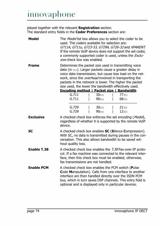
played together with the relevant Registration section.The standard entry fields in the Coder Preferences section are:
Model The Model list box allows you to select the coder to be used. The coders available for selection are:G711A, G711u, G723-53, G729A, G726-32 and XPARENT. If the remote VoIP device does not support the set coder, a commonly supported coder is used, unless the Exclu-sive check box was enabled.
Frame Determines the packet size used in transmitting voice data (in ms). Larger packets cause a greater delay in voice data transmission, but cause less load on the net-work, since the overhead involved in transporting the packets in the network is lower. The higher the packet size used, the lower the bandwidth effectively used.Encoding method | Packet size | Bandwidth G.711 | 30ms | 77kb G.711 | 90ms | 68kb ------------------------------------------------------- G.729 | 30ms | 21kb G.729 | 90ms | 12kb
Exclusive A checked check box enforces the set encoding (Model), regardless of whether it is supported by the remote VoIP device.
SC A checked check box enables SC (Silence Compression). With SC, no data is transmitted during pauses in the con-versation. This also allows bandwidth to be saved wit-hout quality loss.
Enable T.38 A checked check box enables the T.38 Fax-over-IP proto-col. If a fax machine was connected to the relevant inter-face, then this check box must be enabled; otherwise, fax transmissions are not handled.
Enable PCM A checked check box enables the PCM switch (Pulse Code Manipulation). Calls from one interface to another interface are then handled directly over the ISDN PCM bus, which in turn saves DSP channels. This entry field is optional and is displayed only in particular devices.
page 74 innovaphone IP DECT

Registration section:
All non-virtual interfaces additionally have the Registration section after selec-tion of the registration method.
The entry fields for an H.323 registration are:
Gatekeeper Address (pri-mary)
The primary gatekeeper IP address at which the inter-face is to register. If the primary gatekeeper is located on the same device, the local IP address 127.0.0.1 can also be entered here.
Gatekeeper Address (secon-dary)
The secondary gatekeeper IP address at which the inter-face is to register, if registration with the primary gate-keeper fails. If the secondary gatekeeper is located on the same device, the local IP address 127.0.0.1 can likewise be entered here.
Gatekeeper ID It is also sufficient to specify only the Gatekeeper ID (see also the chapter entitled “Administration/Gateway/Gene-ral”).
Name The unique, descriptive H.323 name of the interface or registration.
Number The unique E.164 call number of the interface or regi-stration.
Password / Retype
The security of the registration can be raised by spe-cifying a password (Password). The password must be confirmed (Retype).
Supplementary Services (with Feature Codes)
A checked check box enables the use of additional fea-tures (Feature Codes).See description in the chapter entitled “Administration/Gateway/General”.
innovaphone IP DECT Page 75
The entry fields for a SIP registration are:
Dynamic Group A dynamic group can be added to the H.323 registration.Groups can be configured as static, dynamic-in or dyna-mic-out. For members of static groups, calls are always signalled. It works differently for members of dynamic groups, which register with or unregister from a group dynamically using a function key (Join Group). The diffe-rence between dynamic-in and dynamic-out lies in whe-ther the object is to be contained in the relevant group as standard (in) or not (out).See also description in the chapter entitled “Administra-tion/PBX/Objects”.
Direct Dial Using Direct Dial, a call setup to the specified call num-ber is initiated as soon as the handset is picked up. A conceivable scenario would be a lift emergency tele-phone that is connected with the security control room, for example.
Locked White List
Here, you can specify a comma-separated list of call numbers that may also be dialled in the case of a locked telephone (for example, emergency services numbers, like 110, 911).
Server Address (primary)
The IP address or the proxy server address of the SIP provider (for example sipgate.de, 217.10.79.9), to where the SIP messages (for example, register) are to be sent.
Server Address (secondary)
If the SIP provider has an alternative IP address or proxy server, then it can be entered here. In the event of failure of the primary server (for example, when maintenance is being carried out), the registration is then retained.
STUN Server The STUN server name or IP address must be configured if the telephone uses a private IP address, but the SIP server is accessible under a public IP address. The value is given by the SIP provider or administrator (for example, stun.xten.com or 64.69.76.23). You can choose any STUN server; it does not necessarily have to correspond to the one of the SIP provider.
page 76 innovaphone IP DECT
SIP interfaces (SIP1-4)
In addition to the ISDN interfaces (PPP, TEL1-4, BRI1-4, PRI1-4) and virtual in-terfaces (TEST, TONE, HTTP), there are also four SIP interfaces (SIP1-4), which can be used to obtain a trunk line from a SIP provider, for example. For a des-cription of the entry fields, please refer to the description of the SIP registration above. There are, however, three further entry fields:
ID @ Here, you enter the user ID followed by the SIP provider domain name (for example, [email protected]).
Display Name The name you enter here, which corresponds to the part in front of the @ of the URI, is required for the registra-tion if the number (Account) was not specified (for example, 8111111e0).
Account Likewise in this protocol, a call number is required for the registration, which corresponds to the part in front of the @ of the URI (for example, 8111111e0).
Password / Retype
The password (Password) of the SIP Account must be specified and confirmed (Retype).
Supplementary Services (with Feature Codes)
See entry fields for an H.323 registration.
Dynamic Group See entry fields for an H.323 registration.
Direct Dial See entry fields for an H.323 registration.
Locked White List
See entry fields for an H.323 registration.
Name A descriptive name for the interface.
Disable Disables the relevant interface.
innovaphone IP DECT Page 77
To obtain a trunk line from a SIP provider, you must proceed as follows:
1. Open one of the four SIP interfaces.2. Enter SIP Account data (ID, STUN server, Account, password).3. Under Registrations, link the SIP registration via H.323 to a PBX object of the
Trunk type created beforehand (specification of the GK ID or GK address and the H.323 name or E.164 call number is sufficient).
4. Confirm with OK.A successful registration is displayed in the overview page Administration/Gate-way/Interfaces as follows:
In the example above, the trunk line of the SIP carrier sipgate.de is picked up using the Trunk PBX object with the name SIPTrunk and the call number 8. The dialling of the call number 807031730090 therefore initiates a call at innova-phone AG via the configured SIP carrier.
Virtual interfaces (TEST, TONE, HTTP)
The non-configurable, internal interface TEST is only usable as the destination for a call. If a call is received on this interface, the music on hold contained in the non-volatile memory is played. Incoming calls must be in G.729A or G.723 format; other formats are not supported. Suffix dialling digits are ignored.
The internal interface TONE is only usable as the destination for a call. If a call is received on this interface, it is connected and the configured dial tone (Tones) is played. This happens particularly with least-cost-routing scenarios, where
Registration Corresponds to the Registration entry field of the ISDN interfaces.After selection of H.323, the Registration for H.323 sec-tion is displayed, enabling registration of a SIP Account with a local PBX (for example, innovaphone PBX).After selection of SIP, the Registration for SIP section is displayed, enabling in turn registration with a local SIP PBX (for example, innovaphone PBX).
State(IP of the SIP provi-
der)
Alias(PBX user object)
Registration(IP of the PBX)
For example, 217.10.79.9
(sipgate.de)
H.323 name:E.164 no.SIPTrunk:8
--> 127.0.0.1
page 78 innovaphone IP DECT

the call can only be switched once some of the dialled digits have been analysed. In the meantime, the dial tone is played via the TONE interface. Suffix dialling digits are ignored. The TONE interface can process several calls.
The non-configurable, internal interface HTTP is only usable as the destination for a call. If a call is received on this interface, music on hold, an announcement or some other spoken information is played from a Web server. The configuration only makes sense in combination with the innovaphone PBX.
4.2.2.2.2 CGPN/CDPN MappingsFor every interface, it is possible to store so-called CGPN In, CDPN In, CGPN Out and CDPN Out mappings (Calling Party Number In, Called Party Number In, Cal-ling Party Number Out, Called Party Number Out), enabling call numbers and call number formats to be adjusted for incoming and outgoing calls. The call number formats are as follows:
Clicking the link + or a mapping already created (for example, n->0) opens a popup page, on which the setting for the CGPN In, CDPN In, CGPN Out and CDPN Out mappings can be made:
Each mapping can be specified for a particular call number type:
Unknown Unspecified. Number called in outgoing calls. u
Subscriber Call number in local network. Number called in incoming calls.
s
National Call number with area code. Calling number from home country.
n 0
International Call number with country code and area code. Calling number from abroad.
i 00
Abbreviated Unusual. a
Network-spe-cific
Unusual. x
CGPN In Is used to process the calling number of incoming calls.
CDPN In Is used to process the called number of incoming calls.
CGPN Out Is used to process the calling number of outgoing calls.
CDPN Out Is used to process the called number of outgoing calls.
Unknown The mapping applies to unknown, external calls.
innovaphone IP DECT Page 79

4.2.2.3 Administration/Gateway/VOIPBelow is an overview of all the gateway's configurable VoIP interfaces:
4.2.2.3.1 Interface (VoIP Interfaces)Clicking the relevant VoIP interface (GW1-12 <Name of the VoIP interface>) in the Interface column opens a popup page, on which the VoIP interfaces can be individually configured. Like the PBX objects, this popup page also contains stan-dard entry fields that occur, more or less, in all VoIP interfaces.
These standard fields are:
ISDN The mapping applies to external calls.
Private The mapping applies to internal calls.
Interface The name of the interface. Clicking this name opens a popup page, on which all settings can be made. The set-tings are described in more detail in the following chap-ter “Administration/Gateway/VOIP/Interface (VoIP interfaces)”.
CGPN In, CDPN In, CGPN Out, CDPN Out
Precise details on CGPN In, CDPN In, CGPN Out and CDPN Out mappings are contained in the chapter entitled “Administration/Gateway/Interfaces/CGPN-CDPN Map-pings” further up in the text.
Registration If a terminal has successfully registered with a gateway, then this is indicated in this column through specification of the IP address <Name of the VoIP interface:Call num-ber:IP address>.
Name The descriptive name of the VoIP interface.
Disable A checked check box disables the relevant VoIP interface.
Protocol The protocol to be used, that is, H.323 or SIP. Depending on which protocol is used, the set-up of the entry fields changes.
page 80 innovaphone IP DECT
In the Authorization section, you can store a password for the VoIP interface.
Mode Describes the mode of registration. Possible registration modes are:1. Gateway without Registration - Logs the VoIP interface
(gateway) on to the configured gatekeeper without a registration.
2. Register as Endpoint - Registers a VoIP terminal with the configured gatekeeper.
3. Register as Gateway - Registers a VoIP gateway with the configured gatekeeper.
4. Gatekeeper/Registrar - Is required for managing all gatekeeper registrations on a gateway.
5. ENUM - Is used to register an ENUM connection with the relevant interface.
Gatekeeper Address (pri-mary)
The primary Gatekeeper IP address at which the terminal or gateway is to register via the relevant interface. Only necessary for modes 2 and 3 .
Gatekeeper Address (secon-dary)
The alternative gatekeeper IP address at which the ter-minal or gateway is to register via the relevant interface, if registration with the primary gatekeeper fails. Only necessary for modes 2 and 3 .
Mask By specifying a network mask, incoming calls can be fil-tered. Specification of the network mask 255.255.0.0 therefore allows incoming calls on the relevant interface for terminals from the IP address range 192.168.0.0 - 192.168.255.255 .
Gatekeeper Identifier
It is also sufficient to specify only the gatekeeper ID. Every gatekeeper in a network can be identified by means of its own gatekeeper ID, so that several gatekee-pers can be operated in a network, with each terminal nevertheless identifying the correct gatekeeper by means of Gatekeeper Discovery (uses the multicast address 224.0.1.41).
Password / Retype
The security of the registration can be raised by spe-cifying a password (Password). The password must be confirmed (Retype).
innovaphone IP DECT Page 81

In the Alias List section, you specify the call name (H.323) and the call number (E.164) of the relevant registration. For VoIP end points, you should define the assigned direct dialling number or MSN as the E.164 address, and the name as the H.323 name. For VoIP gateways it is sufficient to define the name.
The standard entry fields in the Coder Preferences section were already des-cribed in chapter “Administration/Gateway/Interfaces/Interface (physical and virtual interfaces)”.
In addition to the standard fields, several advanced settings are available in the H.323 Interop Tweaks section. They are normally not necessary and are merely used to solve compatibility problems with some PBXs:
Name The H.323 name.
Number The E.164 call number.
No Faststart The H.245 faststart procedure is enabled as standard. Outgoing calls are made with faststart, incoming calls with faststart are answered with faststart.A checked check box disables the H.245 faststart proce-dure. Outgoing calls are made without faststart, inco-ming calls with and without faststart are answered without faststart.
No H.245 Tunne-ling
The H.245 tunneling procedure is enabled as standard. The voice data connection is negotiated in the TCP signalling connectiona already available. This can be advantageous in connection with NAT and firewalls.A checked check box disables the H.245 tunneling proce-dure, meaning that a separate TCP connection is set up for this negotiation. This applies to the signalling connec-tion leading out of the gatekeeper.
Suppress HLC A checked check box disables the transmission of HLC (High Layer Compatibility) information elements.
Suppress FTY A checked check box disables the transmission of FTY (Facility) information elements.
page 82 innovaphone IP DECT

4.2.2.3.2 CGPN/CDPN MappingsA detailed description may be found in the chapter entitled “Administration/Ga-teway/Interface/CGPN-CDPN Mappings”.
4.2.2.4 Administration/Gateway/RoutesThe most important task of the gateway is call routing. It determines which calls are accepted and where they are switched to.
Call routing is carried out by the gateway's gatekeeper and is controlled by routes (for voice). For each call direction, a route must be defined. If a call passes se-veral gateways, a relevant route must be defined in each one. A route defines a permitted path for a call, from the interface where the call arrives, to the inter-face from which the call departs. Calls from different interfaces are often handled in the same way. Therefore, calls from several ISDN interfaces (for example, TEL1 and TEL2) or from several VoIP interfaces (GW1-12), for example, can be permitted.
Call switching also often depends on the call number dialled. For this, the validity of routes for calls with particular destination numbers must be defined by means of a map entry. Each map entry defines that calls from the source interfaces spe-cified in the route beginning with the combination of digits specified in the map entry can be connected to the destination interface defined in the route.
All defined routes are displayed row by row in the routing table. For each indivi-dual call, the routing table is searched from top to bottom for a suitable map ent-ry. If it is not possible to switch the call to the identified interface, then the routing table is searched for the next map entry that meets the specified condi-tions. If a map entry was found, the current call is switched to the destination interface of the map entry defined. If no suitable map entry was found, the call is invalid and is not put through.
Suppress Sub-address
A checked check box disables the transmission of Sub-address information elements.
a. From a technical viewpoint, the H.245 protocol does not establish its own TCP connec-tion, but shares the H.225 TCP connection.
innovaphone IP DECT Page 83
4.2.2.4.1 From - ToThe routing table is structured as follows:
To create a new routing entry, you must click the Insert Route below but-ton. A popup page opens, on which the route setting can be made.
This popup page also contains the specification of the map entries. Clicking the Add Map above/below buttons opens the same popup page and adds a map entry at the relevant place. This popup page is structured as follows:
From The source interface from which a call is to be accepted. It may be an ISDN interface (TEL, BRI, PRI, etc.) or a VoIP inter-face (GW1-12).
To The destination interface to which a call is to be switched. It may be an ISDN interface (TEL, BRI, PRI, etc.) or a VoIP inter-face (GW1-12).
CGPN Maps The CGPN (Calling Party Number) map is used for modifying the calling number. It allows the extension to be suppressed for outgoing calls, for example, but also the entire map entry can be made dependent on the calling number.
Description The descriptive name for the route.
Source interface
Here, you select the ISDN or VoIP interface that is to apply as the source for the relevant route. It is also possible to select several sources. The source interfaces available in principle are: RT, RS, TEL, BRI, PRI, PPP, TEST, TONE, HTTP, SIP and GW.
page 84 innovaphone IP DECT
Number In To make the routing decision dependent on a map entry, you must enter the calling number here. If no number is specified here, the map entry is valid for all calls.There are additional variants of call number manipulation available:If a route is to apply to a particular number and all of the digits that are subsequently dialled are to be ignored, the specified call number must be followed by the "!" operator.Some devices require the “#” operator as the signalling cha-racter for the end of a call. For this, the Add # check box can be checked (see description further down in the text).With the “?” operator, it is also possible to replace a variable unknown and known number of characters by a particular one. For example, “???” replace with 1 gives, say for “1234” -> “14”, or “0???” replace with 1 gives, say for “01234” -> “14”, since the known digit 0 is likewise replaced.With the “.” operator, a particular number of characters can be replaced. For example, “...” replace with “123” gives, say for “321” -> “123”.
Number Out
Here, you enter the route’s call number to be replaced, if desi-red. If the call number is to be adopted unchanged, the same call number as in Number In must be specified here.Note: If the calling number was manipulated, the Verify CGPN check box must not be checked, since the checking of the cal-ling number would fail, making the map entry ineffective.
Destina-tion inter-face
Here, you select the interface that is to apply as the destina-tion for the relevant route. The destination interfaces available in principle are: RT, RS, TEL, BRI, PRI, PPP, TEST, TONE, HTTP, SIP, GW, MAP and DISC.
Name Out If the H.323 call name is to be changed, the new call name can be entered here.
Cause (DISC)
If the DISC destination interface was selected, a so-called dis-connection cause (see Appendix C “ISDN error values”) can be additionally specified, to obtain appropriate output on the ter-minal.
innovaphone IP DECT Page 85
For every route definition, advanced settings can be made:
Add UUI If manufacturer-specific data is to be transmitted in the signal-ling channel, for example, the URL for an announcement, then this URL (http://192.168.0.1/webdav) can be specified here.
Final Route A checked check box simulates the end of the routes. If further routes are to follow, they are ignored.
Final Map A checked check box simulates the end of the map entries. If further map entries are available, all further map entries are ignored.
Exclude from Auto CGPN
If the Automatic CGPN Mapping check box was checked in chapter “Administration/Gateway/General”, the relevant route can be excluded from the automatic correction of all calling numbers by checking this check box.
Verify CGPN
The routing decision is normally made on the basis of the rou-tes themselves and the map entries defined in the routes. With a checked check box, the routing decision is made on the basis of the CGPN maps. This means that first the calling number is checked and, only if the calling number matches, is the routing table further processed and call switching, for example, takes place.Since this only applies to the verification and restriction of par-ticular numbers, no manipulation of the call number takes place here. In this way, access to a chargeable trunk line, for example, can be restricted to certain extensions (selective direct outward dialling).If the Automatic CGPN Mapping check box was checked in chapter “Administration/Gateway/General”, the check is app-lied to the number already corrected.
Interwor-king (QSIG)
A checked check box enables translation of H.323 or SIP to QSIG. Here, no translation from QSIG to H.323 or SIP takes place, rather, the transmission is transparent (is used where PBXs of the same kind are linked via VoIP).
Force Enblock
A checked check box enforces enbloc dialling. This means that if a map entry applies, all subsequently dialled digits are col-lected until more than four seconds have passed since the last digit was dialled.
page 86 innovaphone IP DECT
Clicking the name of a route (for example, TEL1:exchange) filters the display of the routes by the set interface. Clicking the name of the route a second time again shows the routes that are not associated. If, for example, several routes have been created for the TEL1 interface, then clicking one of the TEL1 interfaces hides all other routes that do not have TEL1 selected as the source or destination interface.
The adjacent arrow button (__>) can be used to edit routes.
4.2.2.4.2 CGPN MapsIt is also often necessary to define routes depending on the calling number. Just as maps are added to routes, so-called CGPN maps must be added to the maps for this purpose. This not only allows calling numbers to be manipulated in order to suppress the extension for outgoing calls, for example, but also the entire map to be made dependent on the calling number.
The arrow button (__>) in the CGPN Maps column can be used to define and edit such maps.
Add # A checked check box transmits the hash character (#) to mark the end of a call number. This is only required for terminals that do not recognise the end of the call number (such as Cisco terminals, for example).
Disable Echo Can-celler
A checked check box suppresses echo cancellation for the rele-vant map entry. This is normally only necessary if the connec-tion used as the voice connection is not to perform echo cancellation, as is the case with modems, for example.
Call Coun-ter max
If there is insufficient bandwidth available, a name can be entered in the Call Counter field, and the maximum number of calls permitted for the relevant route can be entered in the max field.
Number In The calling number. The CGPN map is valid if the inbound E.164 call number matches the call number or dial prefix set here.
Name In The calling name. The CGPN map is valid if the inbound H.323 call name matches the name set here.
Number Out
Here, you enter the call number or dial prefix to be replaced for the switching.
innovaphone IP DECT Page 87
4.2.2.5 Administration/Gateway/CDR0-1
The transmission of the so-called CDRs (Call Detail Records) is disabled as standard (Off). After selection of a CDR type, the transmission of detailed CDRs is enabled, as are the relevant entry fields. To prevent data loss in the event of failure of the first CDR server (CDR0), it is possible to specify a second CDR server (CDR1).
Off CDR is disabled.
TCP The device transmits the CDR entries via a TCP connection.• In the Address field, you enter the IP address at which
the TCP connection is to be set up.
• In the Port field, you specify the port to which the connec-tion is set up.
SYSLOG The CDR entries are transmitted to a syslog recipient (also re-ferred to as syslogd, syslog server or syslog daemon), which is then responsible for their further evaluation or stora-ge.
• In the Address field, you enter the IP address of the syslogd server.
• In the Class field, you enter the desired message class that will be responsible for further processing of the CDR entries.
page 88 innovaphone IP DECT

4.2.2.6 Administration/Gateway/CallsIn the Calls gateway overview page, all calls actively being made can be moni-tored. This is advantageous for diagnostic purposes in particular, since the exi-stence of possible network problems, for example, is immediately visible (see Coder):
HTTP The CDR entries are transferred to a Web server, where they can be further processed. Each individual CDR entry is transfer-red as form data to the Web server in HTTP GET format.
• In the Address field, you enter the IP address of the Web server that carries out further processing of the transmit-ted data.
• In the Path field, you enter the relative URL of the form program on the Web server.
The device will make a HTTP GET request to the Web ser-ver on the entered URL, followed by the URL-encoded CDR entry. If, for example, a page named /cdr/cdr-write.asp with a form that expects the log message in parameter msg exists on a Web server, then the value /cdr/cdrwrite.asp is entered. The device will then make a GET /cdr/cdrwrite.asp?event=sys-log&msg=logmsg request to the Web server.
Interfaces Display of the calling interface.Protocol Display of the protocol used on the calling side.Coders Display of the coder used on the calling side, for example,
G711AB(2,0,0). The values in brackets have the following meaning, in order:Round trip = Transit time of a data packet from A to B and back again.Jitter = Latency time (time interval from the end of an event up to the start of the response).Loss = Number of lost packets (packet loss).
Number Display of the called number.State Possible states: Alerting, Calling, Connected, Disconnecting.
innovaphone IP DECT Page 89
4.2.3 Administration/DownloadThe configuration of the VoIP device can be backed up using this menu.
4.2.3.1 Administration/Download/ConfigThis function allows to save the current configuration of the VoIP device. When clicking the Download link, a popup page opens, in which it can be specified whether to save the configuration file as a txt file or immediately open it with an editor.
4.2.4 Administration/UploadThere are several ways to update the VoIP device.
4.2.4.1 Administration/Upload/ConfigThis function allows you to load a saved configuration (see chapter entitled “Ad-ministration/Diagnostics/Config Show”) onto the device.
By specifying path and file name of the configuration file to be loaded in the Filefield and then clicking the Upload button, the configuration file is loaded into the device.
Here, it is to be noted that the configuration file is loaded into the device’s volatile memory. This means it is neither permanently backed up nor immediately ope-rative. The device therefore must be briefly reset. More detailed information on resetting the device may be found in the chapter „Administration/Reset“.
Note
Detailed informations respectively the status display by the Ready LED while uploading files to the device can be found in the innovaphone knowledge-base article „How to Reset IPXXX , factory default, led behaviour, tftp mode,clear config,gwload“ (http://www.innovaphone.com/inno-kb).
page 90 innovaphone IP DECT
4.2.4.2 Administration/Upload/FirmwareThis function allows you to manually upload a new firmware version onto the VoIP device. This can be automated by configuring an update server as described in the chapter “Configuration/General/Update”. New firmware versions can be obtained from a certified innovaphone dealer or directly via the innovaphone ho-mepage (http://www.innovaphone.com).
By specifying path and file name of the configuration file to be loaded in the Firmware File field and then clicking the Upload button, the configuration file is loaded into the device.
Whilst loading the new firmware, you are advised not to interrupt the loading procedure under any circumstances.
If the loading procedure is nevertheless interrupted, the device should under no circumstances be switched off afterwards. Rather the procedure should be re-peated once the problem has been eliminated.
Take a look at the documents supplied with the new versions to find out whether new boot firmware also has to be loaded. If this is the case, it must be ensured (if specified) that the required sequence of boot code and firmware update is ob-served.
The new firmware is not activated directly. A reset must be performed to activate the new version. The immediate reset and reset when idle links are provided for this purpose. More detailed information on resetting the gateway is contained in the chapter entitled “Administration/Reset”.
4.2.4.3 Administration/Upload/RadioThis function can be used to load a new radio firmware version onto the VoIP device. New radio firmware versions can be obtained from a certified innovapho-ne dealer or directly from Kirk.
By specifying path and file name of the radio firmware to be loaded in the Radio File field and then clicking the Upload button, the radio firmware is loaded into the device.
It is necessary to ensure that all active calls are terminated as soon as the radio firmware is loaded onto the device.
Whilst loading the new radio firmware, you are advised not to interrupt the loa-ding procedure under any circumstances.
If the loading procedure is nevertheless interrupted, the device should under no
innovaphone IP DECT Page 91

circumstances be switched off afterwards. Rather the procedure should be re-peated once the problem has been eliminated.
The new radio firmware is not activated directly. A reset must be performed to activate the new version. The immediate reset and reset when idle links are provided for this purpose. More detailed information on resetting the device is contained in the chapter entitled “Administration/Reset”.
4.2.4.4 Administration/Upload/BootThis function can be used to load a new boot code version onto the VoIP device. New boot code versions can be obtained from a certified innovaphone dealer.
By specifying path and file name of the boot code firmware to be loaded in the Boot File field and then clicking the Upload button, the boot code firmware is loaded into the device.
Whilst loading the new boot code firmware, you are advised not to interrupt the loading procedure under any circumstances.
If the loading procedure is nevertheless interrupted, the device should under no circumstances be switched off afterwards. Rather the procedure should be re-peated once the problem has been eliminated.
The new boot code is not activated automatically. A reset must be performed to activate the new version. The immediate reset and reset when idle links are provided for this purpose. More detailed information on resetting the device is contained in the chapter entitled “Administration/Reset”.
Take a look in the documents supplied with the new versions to find out whether new protocol firmware also needs to be loaded.
4.2.5 Administration/DiagnosticsThe Diagnostics menu can be used to monitor the operating state of the device.
4.2.5.1 Administration/Diagnostics/LoggingUsing the Syslog link, the log messages of the device can be viewed directly in active operation. The messages are continuously automatically updated and are scrolled upwards, out of the window.
Only messages that were enabled in the Logging submenu are displayed. The
page 92 innovaphone IP DECT
following settings can be enabled:
Clicking OK saves the settings made.
4.2.5.2 Administration/Diagnostics/TracingUsing the trace (buffer) link, the trace information of the VoIP device can be viewed and saved. In the process, a text file log.txt is generated, which displays the current trace in a new browser window.
Using the trace (continuous) link, the continuous trace information of the de-vice can be viewed and saved. In the process, a text file clog.txt is generated, which displays the current trace in a new browser window. As already mentio-
TCP All TCP connections.PPP All PPP connections.Relay Calls All calls that go via the Relay – only visible for devices with S0
or S2m interface.
Relay Routing
All calls that must be routed via the Relay – only visible for devices with S0 and S2m interface.
DECT master
All DECT master connections – only visible for IP DECT systems.
DECT radio
All DECT radio connections – only visible for IP DECT systems.
H.323 Registrati-ons
All H.323 registrations.
SIP Regi-strations
All SIP registrations.
Config Changes
All configuration changes.
TEL1-n All TEL1-n connections – only visible for devices with TEL interface.
PPP All PPP connections – only visible for devices with PPP inter-face.
BRI1-n All BRI1-n connections – only visible for devices with BRI interface.
PRI1-n All PRI1-n connections – only visible for devices with PRI interface.
innovaphone IP DECT Page 93
ned, the messages are continuously automatically updated and are scrolled up-wards, out of the window.
For both trace variants, only messages that were enabled in this menu are dis-played. Not every section and not every setting is visible; this will depend on which device is being used.
DECT section:
Interfaces section:
VOIP section:
System Information on the DECT system.Master Information on the DECT master.Radio Information on the DECT radio.
PPP Information on the PPP interface.TEL1-n Information on the TEL1-n interface.BRI1-n Information on the BRI1-n interface.PRI1-n Information on the PRI1-n interface.prot The prot check boxes after the individual interface settings
give information on the protocol used.
H.323/RAS
Information on H.323 RAS.
H.323/H.225
Information on H.323/H.225.
H.323/H.245
Information on H.323/H.245.
H.323/T.38
Information on H.323/T.38
H.323/T.30
Information on H.323/T.30
SIP/Mes-sages
Information on SIP/messages.
SIP/Events
Information on SIP/events.
SIP/T.38 Information on SIP/T.38.DSP Information on DSP.
page 94 innovaphone IP DECT
IP section:
Clicking OK saves the settings made.
4.2.5.3 Administration/Diagnostics/Config ShowConfig Show enables the output of the current configuration of the VoIP devicein text format.
The current configuration can also be saved in a file using the Save Frame Asfunction (depending on the browser used). It is also possible to select (highlight) the entire text (Ctrl-A) and copy it to the Clipboard using the right mouse button and the context menu (or Ctrl+C). The configuration can now be copied into any text editor (Ctrl+V) and saved.
A configuration backed up this way can be fully or partially loaded again. In this way, the configuration can be backed up and restored, or reference configurati-ons can be created and loaded onto a number of devices.
4.2.5.4 Administration/Diagnostics/PingIt is possible to execute a ping on a particular destination host (IP address), since for test purposes it is often necessary to execute a ping command directly from the VoIP device. This makes it possible to check whether a network address
DSP con--trol mes--sages
Information on DSP control messages.
DSP data messages
Information on DSP data messages.
PPP Information on the PPP protocol.PPTP Information on the PPTP protocol.PPoE0-1 Information on the PPoE0/1 protocol.DHCP0-1 Information on the DHCP0/1 server.HTTPCLI--ENT
Information on the HTTP client.
HTTPCLI--ENT ver--bose
Detailed information on the HTTP client.
innovaphone IP DECT Page 95
(PC, printer, telephone, etc.) is accessible. If an address is accessible, Reply from <host> is displayed to the sender. If the address is not accessible, No Reply from <host> is displayed.
4.2.6 Administration/ResetIn addition to reset the device by the hardware reset button, there are three more ways given by the webbrowser, to reset the VoIP device.
4.2.6.1 Administration/Idle ResetWith an Idle Reset, the VoIP device is reset as soon as no more active calls are being carried out.
4.2.6.2 Administration/Reset/ResetWith a normal Reset, the device is immediately reset. All active calls are lost.
4.2.6.3 Administration/Reset/TFTPWith a TFTP Reset, the VoIP device is transferred to TFTP mode. In this mode, the device can only be accessed with the GWLoad tool and thus allocated an IP address. Further information on the innovaphone GWLoad tool may be found in the innovaphone Knowledgebase.
Note
Informations to the reset function respectively the hardware reset button on device are contained in Appendix A „Connectors and control elements“ inside Table 1 „Indicators and Connectors“ („Reset“).More detailed informations can be found in the innovaphone knowledgebase article „How to Reset IPXXX , factory default, led behaviour, tftp mode,clear config,gwload“ (http://www.innovaphone.com/inno-kb/).
page 96 innovaphone IP DECT

Appendix A: Connectors and control elements
Indicators and connectors
1 2 3 4 5 6 7 8 9Fig. 1 - Indicators and connectors of the IP800
Pos. Symbol Description and function
1 TEL1-4 ISDN-Socket (basic-rate-interface) for connecting an ISDN device.
2 PPP ISDN-Socket (basic-rate-interface) for connecting an ISDN device or terminal equipment.
3 pwr LED to indicate the internal power supply for the seperate interface is active.
4 link LED to indicate that data is being sent or received on the ETH0/1 interface. This applies analogously to all other LEDs.
5 ETH0-1 RJ45-socket for connecting a 100 Mbps Ethernet (10/100Base-T auto sense).
6 100M LED to indicate that the 100 Mbps network for the ETH0/1 interface is active.
innovaphone IP DECT Page 97

7 Ready Three color LED that indicates the status of the device.LED off means, waiting for action (for example reset).Green LED means the device is ready for operation.Green fast blinking LED means config clear or firm-ware/bootcode update.Orange LED means the device is in TFTP-ModeRed LED means the device has an error or is reboo-ting.Red fast blinking LED means firmware/bootcode upload.See also description to „Reset“ in Table 1 „Indicators and connectors of the IP800“.
8 Compact Flash
Slot for inserting a compact-flash memory card.
9 Reset In addition to reset the device by the webbrowser, there are three (four) more ways given by the reset button, to reset the device.Short Reset: A short reset is restarting the device. Doing this will disrupt all active calls.Middle Reset (TFTP-Reset): The device is moving into TFTP-Mode, if holding the reset button until the Ready LED is blinking one-two times and then loose holding of the reset button.All ISDN-LEDs will be deleted and the Ready LED will be displayed in orange.Long Reset (Factory-Reset): Holding the reset button a longer time the Ready LED will blink 4-6 times and change to red. If loosing the hold on the reset button now, the deletion of the con-figuration is beginning. The Ready LED will be dis-played 5 seconds in red and after that it will start to blink very fast in red-green and delete the display of all ISDN-LEDs. The device will go into TFTP-Mode and the Ready-LED will be displayed in orange.Power-Cycle: Means to disrupt the device from the power supply. Works technically and visually like the short reset.
Table 1 Indicators and connectors of the IP800
page 98 innovaphone IP DECT

The serial number labelThe serial number label may be found on the device packaging and on the un-derside of the housing.
The MAC address is also the serial number of the IP800.
The first three constant hexadecimal digits separated by a hyphen (`-´) are innovaphone’s manufacturer identification code (009033 or 00-90-33), whilst the last three hexadecimal digits (001504 or 00-15-04) are the consecutive serial number of your IP800.
Note
Informations respectively the software reset function by the webbrowser are contained in chapter „Administration/Reset“.More detailed informations can be found in the innovaphone knowledgebase article „How to Reset IPXXX , factory default, led behaviour, tftp mode,clear config,gwload“ (http://www.innovaphone.com/inno-kb).
Fig. 2 - Serial number label of the IP800
innovaphone IP DECT Page 99
Appendix B: TroubleshootingIn our experience, some problems occur more frequently than others. These problems are listed in Table 2 below, which also gives advice on how to solve them.
Typical problemsSymptom Description Action
The VoIP device does not respond. Ready, Link and 100M. LEDs are permanently on.
The VoIP device is waiting for a firmware download.
• Perform a quick reset by pressing the Reset button.
The VoIP device does not respond. Ready LED is on, Link LED flashes irregularly.
The Ethernet connection is not working.
• Check the Ethernet cabling.
The VoIP device does not respond. Ready and Link LEDs are on, 100M. LED flashes during attempted access.
The VoIP device has an incorrect IP address configured.
• Set the IP parameters correctly.
In the as-shipped state, the VoIP device does not assign an IP address to the PC.
When the device is turned on, the DHCP client is active.
• Press the Reset button briefly.
• Have an IP address assigned to the PC again.
Calls can be established to a remote VoIP device, but no communication is possible.
The required bandwidth for the transfer of the voice data is not available.
• Configure a more efficient voice coding for the remote VoIP device.
Calls can be set up to a remote VoIP device, but no voice connections can be established.
The media channel cannot be set up, since the two VoIP devices do not have a common voice encoder.
• Make sure that the „exclusive“ check box is disabled.
page 100 innovaphone IP DECT

NAT and firewallsIf there is a firewall protecting your network from the Internet and connections
Calls can be set up to a remote VoIP device, but no voice connections can be established.
The media channel cannot be set up, since the two VoIP devices do not have a common voice encoder.
Only the media channel is set up directly between the two VoIP devices; all signalling connections are operated via the gatekeeper.• Make sure that both VoIP
devices have a correct IP routing configuration, in particular subnet mask and standard gateway.
Calls to a remote telephony gateway are constantly rejected.
The device does not support overlapped sending.
• Add a hash (#) to the dial prefix of the route leading to this gateway to force en-bloc dialling.
The VoIP device loses its configuration after it has been disconnected from the power supply.
The configuration has not been saved in the non-volatile memory.
• Save the configuration to the non-volatile memory each time you make any changes.
The VoIP device is connected to the network behind a firewall and the configuration is not working.
The firewall does not allow access to the VoIP device.
• Enable VoIP device access for the service tcp/80 (http) in the firewall.
The VoIP device is connected to the network behind a firewall and no connections to other VoIP devices can be established.
The firewall does not support the H.323 protocol.
• Enable “H.323 Firewalling” in your firewall software and, if necessary, “H.323 NAT”. Refer to your firewall documentation for this purpose.
• See chapter “NAT and firewalls” for more information.
Table 2 Troubleshooting
innovaphone IP DECT Page 101

are to be set up to remote terminals via the Internet, then appropriate configuration of the firewall must be ensured.
Firewalls normally have two jobs. They control access to devices and network areas within your network and they implement the IP address translation in networks that do not have their own regular network address (NAT). NAT can also be implemented by routers.
In connection with Voice over IP, both functions require a detailed analysis of the data stream in order to be implemented. This must be performed by the firewall or router firmware.
If the product you are using does not have H.323 firewalling, there are two ways of proceeding:
• Release the path in the firewall for all required data to and from the VoIP device.
Although this solution is usually not well received by network administrators, it does not present a security problem, since the VoIP device, as a dedicated device, does not perform any services other than Voice over IP. No security gaps are caused in a network by opening the path to and from the device.
The number of ports to be released can be restricted if the H.323 devices whose data is to cross the firewall are all innovaphone devices.
The following ports must be released in both directions:
• Tcp: destination port 80 (http), any source port, for configuration
• Tcp: destination port 1720 (h.225), any source port for VoIP calls
• Udp: destination port >= 2050, source port 5004 and 5005 (RTP), for VoIP calls
The following ports should also be released if the RAS protocol is used:
• Udp: destination port 1718
• Udp: destination port 1719
• Udp: source port 1719
page 102 innovaphone IP DECT
The number of ports to be released cannot be restricted if the device has to communicate with third-party products. It is thus necessary to release all ports to and from the device.
• The device is placed in front of the firewall, so that the data stream does not have to pass the firewall. In this case, you will not be able to set up any voice connections from within the network to the device (for example, with innovaphone Softphone PCs).
If the network is operated in NAT mode and the product you are using does not support H.323 NAT, then it is not possible to operate beyond the firewall.
VoIP and heavily loaded WAN linksIf voice data is transmitted over heavily loaded, narrowband WAN links, the voice quality can be affected if the respective links can no longer ensure adequate transmission quality.
Prioritisation of voice data on the WAN links can help here. This can usually be achieved by the routers used.
Direct use can be made of the "Prioritisation of H.323 voice data" function, if it is supported by your router.
If you router is able to prioritise on the basis of the ToS field (Type of Service), you can use this function. The VoIP device sets the ToS Priority field to the value 0x10 for all IP packets that it sends. This value can be changed, if necessary, under the chapter “Configuration/IP/Settings” .
If this is not the case, the function “Prioritisation according to source/destination address” can be used, if available. In this way, data packets from and to the device are prioritised. This in effect corresponds to the prioritisation of voice data as above.
In any case, the maximum size of packets transmitted over the WAN link (often referred to as MTU size) should be restricted to a value smaller than 800 bytes. This ensures that, in spite of the prioritisation of voice data, larger data packets
Tip
You can specify hexadecimal, octal or decimal values: the entries 0x10, 020 and 16 are all equivalent. The value set for the ToS Priority field should be the same on all used devices.
innovaphone IP DECT Page 103

do not block the line for an extended period of time during transmission.
Some routers are able to prioritise but are unable to interrupt the transmission of larger packets once it has started. This can result in poor quality in spite of prioritisation. In such a case, you should check whether this interruption can be separately enabled. Some routers refers to this function, somewhat confusingly, as interleaving.
page 104 innovaphone IP DECT

Anhang C: ISDN-ErrorcodesThe following table shows the isdn errorcodes after Q.931 standard:
Error-code (hex)
Error-code, Bit
8 to 1 setted (hex)
Error-code
(dezimal)
Meaning
0x1 0x81 1 Unallocated number
0x2 0x82 2 No route to specified transit net-work
0x3 0x83 3 No route to destination
0x6 0x86 6 Channel unacceptable
0x7 0x87 7 Call awarded and being delivered in an established channel
0x10 0x90 16 Normal call clearing
0x11 0x91 17 User busy
0x12 0x92 18 No user responding
0x13 0x93 19 No answer from user (user aler-ted)
0x15 0x95 21 Call rejected
0x16 0x96 22 Number changed
0x1A 0x9A 26 Non-selected user clearing
0x1B 0x9B 27 Destination out of order
0x1C 0x9C 28 Invalid number format
0x1D 0x9D 29 Facility rejected
0x1E 0x9E 30 Response to STATUS ENQUIRY
innovaphone-Gateway Seite 105

0x1F 0x9F 31 Normal, unspecified
0x22 0xA2 34 No circuit/channel available
0x26 0xA6 38 Network out of order
0x29 0xA9 41 Temporary failure
0x2A 0xAA 42 Switching equipment congestion
0x2B 0xAB 43 Access information discarded
0x2C 0xAC 44 Requested circuit/channel not available
0x2D 0xAD 47 Resources unavailable, unspeci-fied
0x31 0xB1 49 Quality of service unavailable
0x32 0xB2 50 Requested facility not subscribed
0x39 0xB9 57 Bearer capability not authorised
0x3A 0xBA 58 Bearer capability not presently available
0x3F 0xBF 63 Service or option not available, unspecified
0x41 0xC1 65 Bearer capability not implemen-ted
0x42 0xC2 66 Channel type not implemented
0x45 0xC5 69 Requested facility not implemen-ted
0x46 0xC6 70 Only restricted digital informa-tion bearer capability is available
0x4F 0xCF 79 Service or option not implemen-ted, unspecified
0x51 0xD1 81 Invalid call reference value
Seite 106 innovaphone-Gateway

0x52 0xD2 82 Identified channel does not exist
0x53 0xD3 83 A suspended call exists, but this call identity does not
0x54 0xD4 84 Call identity in use
0x55 0xD5 85 No call suspended
0x56 0xD6 86 Call having the requested call identity has been cleared
0x58 0xD8 88 Incompatible destination
0x5B 0xDB 91 Invalid transit network selection
0x5F 0xDF 95 Invalid message, unspecified
0x60 0xE0 96 Mandatory information element missing
0x61 0xE1 97 Message type non-existent or not implemented
0x62 0xE2 98 Message not compatible with call state
0x63 0xE3 99 Information element non-exi-stent or nor implemented
0x64 0xE4 100 Invalid information element con-tents
0x65 0xE5 101 Message not compatible with call state
0x66 0xE6 102 Recovery on timer expiry
0x6F 0xEF 111 Protocol error, unspecified
0x7F 0xFF 127 Interworking, unspecified
innovaphone-Gateway Seite 107
page 108 innovaphone IP DECT
Appendix D: SupportIf needed to enlist the support of a dealer, the following information should be ready:
• The full version details of the device. These details may be found on the welcome page of the device (see chapter entitled “Configuration/General/Info”).
• A trace showing the error situation (see chapter entitled “Administration/Diagnostics/Tracing”).
• The entire configuration as displayed by Config Show (see chapter entitled “Administration/Diagnostics/Config Show”).
• The serial number, which may be found on the serial number label on the underside of the housing or on the welcome page of the device (see Appendix B “Connectors and control elements” or chapter “Configuration/General/Info”).
Firmware uploadThe innovaphone VoIP devices are not delivered with the latest firmware, which means that a firmware upload is usually necessary.
New firmware versions can be obtained in the download area (http://download.innovaphone.com) of the innovaphone homepage.
innovaphone homepageThe innovaphone homepage (http://www.innovaphone.com) contains all current service packs, boot codes, hot fixes, firmware updates, manuals, datasheets, etc. It is also possible to request the innovaphone newsletter to stay up to date with current innovaphone news.
In future, it will be possible to make complaints online via the innovaphone homepage. This enables a simpler and faster processing procedure.
Appendix E: Configuration of the update serverIt is possible to update the firmware and configuration of a large number of innovaphone devices in a distributed environment by automated means.
This is done by storing the configuration and firmware information on a standard Web server, which in turn is called up the individual devices.
There are two modules in the device which work in tandem. The first is known as „UP0“ and acutally executes the upload and download of configuration information as well as the download of updated firmware. UP0 is controlled by commands as detailed below.
The second module is known as „UP1“. It serves to poll a given website for changed configuration information. If certain conditions are met, UP1 will issue commands to UP1 to perform the requested updates.
System requirements• One or more Web server(s) accessible by the devices.
• The Web servers tested were MS IIS and the Apache server. It should, however, also work with all other common Web servers.
• For best results, the Web server should be able to manage a large number of simultaneous HTTP sessions. MS Personal Web Server, for example, is not a suitable Web server, since it manages a maximum of 10 simultaneous HTTP sessions.
InstallationTo be able to transfer device configurations onto the Webserver, the latter must allow HTTP PUT requests. All other functions require HTTP GET authorisation.
Since all HTTP requests are executed unauthenticated, the Web server must allow anonymous reading and possibly also anonymous writing.
To allow HTTP PUT commands on a MS IIS, the read and write check box must be enabled in the configuration of the relevant virtual directory.
ConfigurationDetailed information on how the URL parameter of the update server is
innovaphone IP DECT Page 109

configured on the innovaphone devices may be found in the chapter entitled “Configuration/General/Update”.
Note here that the URL parameter must point precisely to the location of the file with the contained maintenance commands. It is also to be noted that this URL (just like all other URLs used by innovaphone devices) does not support host names. Therefore, a valid IP address always has to specified.
If the URL happens to end with a ‘/’, then a standard file name based on the product description is used. If, for example, the URL is http://1.2.3.4/configs/ , then it is extended in the case of an IP1200 as follows: http://1.2.3.4/configs/update-ip1200.htm . The product name is specified in the first line in chapter “Configuration/General/Info”. The file extension is irrelevant here. The extension *.txt or *.htm or no file extension at all is possible. In relation to URL specifications, note that some Web servers differentiate between upper case and lower case letters.
Running maintenanceThe update file is immediately read and also immediately executed. After a device restart, the update server is automatically queried periodically in accordance with the interval set.
When the maintenance file has been successfully received, it is executed sequentially. Theoretically, all commands that can be transmitted to the device in a Telnet session or that occur in a configuration file can be used in the maintenance file.
Maintenance commandsAdditional commands implemented specially for the update server are available.
The maintenance file is executed every time (depending on the interval set), as soon as it is received.
Check commandIn most cases, however, the maintenance file should be executed not every time as soon as it is received, but once only. Assuming that a secure configuration is to be loaded onto several devices, then it is best if this is done from one device. This can be achieved with the check command:
mod cmd UP1 check <final-command> <serial>
page 110 innovaphone IP DECT
innovaphone devices have an internal variable that is initially empty (or empty if the device was reset with the standard settings) called UPDATE/CHECK. The check command compares the content of <serial> with the UPDATE/CHECK variable. If both match, all further processes of the maintenance file are terminated.
If they differ, the remaining processes are executed. When the last process has been executed, the UPDATE/CHECK variable is overwritten with the content of <serial>, and the content of <final-command> is executed. The following commands are usable content for <final-command>
• ireset: Resets the device as soon as it is not being actively used.
• reset: Resets the device immediately.
• iresetn: Resets the device as soon as it is not being actively used and a reset is required.
• resetn: Resets the device immediately if a reset is required.
• ser: Is a global variable and not a function.
Time commandOften it is preferred to perform such changes at particular times (for example, at night when no work is being done). This can be achieved with the times command:
mod cmd UP1 time [/allow <hours>]
The time command compares the current time with the content of <hours>. <hours> is a comma-separated list of specified hours, within which execution of the maintenance file is possible. If the content of <hours> with the restriction does not match, all further processes are terminated. The following hours are considered valid times, within which execution of the maintenance file makes sense.
mod cmd UP1 time /allow 12,22,23,0,1,2,3,4
With this command, execution of the maintenance file is allowed from 12:00 to 12:59 hrs and from 22:00 to 04:59 hrs. If the device does not have a time, all processes are terminated.
mod cmd UP1 time [/allow <hours>] [/initial <minutes>]
If the /initial parameter is set, no further commands are executed within the specified number of minutes <minutes>, once the device has been reset. This was implemented to avoid a firmware download and the overwriting of Flash
innovaphone IP DECT Page 111
memory during device installation.
mod cmd UP1 time /allow 12,22,23,0,1,2,3,4 /initial 6
With this specification, all processes of the maintenance file are suppressed within the first six minutes and within the valid times specified in the /allow parameter after every device restart. If the /initial parameter was set, new devices (or devices that were reset with the standard settings) can, after a restart, receive the maintenance file within the number of minutes specified in the /initial parameter, even if they lie outside the valid times as specified in the /allow parameter. This allows new devices to receive a current standard configuration quickly.
Prot commandTo initiate a firmware update, the following command can be executed:
mod cmd UP0 prot <url> <final-command> <built-serial>
This command downloads new firmware (if available) from the specified URL onto the device. Finally, the <final-command> is executed.
innovaphone devices have an internal variable that is initially empty (or empty if the device was reset with the standard settings) called UPDATE/PROT. The prot command compares the content of <build-serial> with the UPDATE/PROT variable. If both match, no firmware is downloaded. If the UPDATE/PROT variable is not set (new devices or after a device restart), the content of <build-serial> is compared with the built number of the current firmware. Once the firmware has been successfully downloaded, the UPDATE/PROT variable is overwritten with the content of <build-serial> . Note that the <build-serial> parameter is not compared with the firmware version currently loaded. It is the responsibility of the administrator to keep this standard.
If the <url> parameter ends with a slash (‘/’), a standard firmware file name is appended to the URL depending on the product description (for example, IP1200.bin for an IP DECT system).
mod cmd UP0 prot http://192.168.0.10/firm/ip1200.bin ireset 04-5656
The command
mod cmd UP0 prot http://192.168.0.10/firm/ ireset 04-5656
determines whether the firmware version 04-5656 was already installed. If this
page 112 innovaphone IP DECT

is not the case, the current firmware is downloaded from the address 192.168.0.10/firm/ip1200.bin, the UPDATE/PROT internal variable is overwritten with 04-5656 and, finally, the device is reset as soon at it is not being actively used.
Boot commandWith the boot command, the boot code is updated and this is done in the same way as with the prot command.
mod cmd UP0 boot <url> <final-command> <built-serial>
The command
mod cmd UP0 boot http://192.168.0.10/firm/ ireset 205
determines whether the boot code version 205 was already installed. If this is not the case, the current boot code is downloaded from the address 192.168.0.10/firm/bootip1200.bin, the UPDATE/BOOT internal variable is overwritten with the version number of the downloaded boot code (205) and, finally, the device is reset as soon as it is not being actively used.
SCFG commandIf the UP0 interface is being used, then the device configuration can be stored on a Web server.
mod cmd UP0 scfg <url>
This command instructs the device to upload its current configuration to the <url>. This can be achieved with the HTTP PUT command. The url must be writable. The following constants can be used in the url:
ExampleA Web server exists at the address 192.168.0.10 with a subdirectory called configs. In this directory, there are two further subdirectories, in which the current firmware files for all innovaphone devices are stored.
Clients provide the DHCP server with the option #215 as http://
Sequence Replaces Example#d Current date and time 20051010-170130#m MAC address of the device 00-90-33-03-0d-f0#h Device hardware number IP1200-03-0d-f0
innovaphone IP DECT Page 113

192.168.0.10/configs/. In this directory, there is a file update-ip1200.htm , which processes the following lines:
mod cmd UP1 times /allow 23,0,1,2,3,4 /initial 6mod cmd UP0 scfg http://192.168.0.10/configs/saved/#h.txtmod cmd UP0 prot http://192.168.0.10/configs/04-5679 /ser 04-5679mod cmd UP1 check ser 20040330-01config change PHONECFG0 /coder G729A,60, /lang eng /protectconfig change PHONEAPP0 /f4-10 BellOff /f4-v0 %1BE /f5-10 BellOn /f5-v0 %1BFconfig writeconfig activateiresetn
There is also the file update-ip3000.htm, which reads the following two lines:
mod cmd UP1 time /allow 23,0,1,2,3,4mod cmd UP0 prot http://192.168.0.10/configs/04-5679 /ser 04-5679
This example demonstrates how the configuration of a device is stored on a Web server; all IP1200 devices are then instructed to load/update the firware version 04-5679 in the time period 23:00 hrs to 04:59 hrs. New devices are updated after a restart and after the specified six minutes have elapsed. The devices are configured so that they use the G729 codec with a frame size of 60ms, the language setting is English and the configuration is write-protected. Therefore, only an administrator with appropriate authorisation can change this file. In addition, two standard functions were programmed for the device.
IP3000 devices are updated to firmware version 04-5679 in the time period 23:00 hrs to 04:59 hrs.
page 114 innovaphone IP DECT
Appendix F: Configuration of an NTP server/clientIf a network does not have an NTP server, a public time server can be used. The TU Berlin, for example, provides a time service at the IP address 130.149.17.21. This service is a voluntary service, and no claims can be made with regard to its availability.
Any Windows server can operate as the NTP server. Equally, there are various NTP software packages for Windows and Unix/Linux platforms.
The innovaphone VoIP devices also work simultaneously as NTP servers. If several devices are being used, one device can synchronise with a time server (external if need be), and all other devices, in turn, can synchronise with this one device.
The VoIP device will then operate as the time service and will transmit the correct time to the other devices. The synchronisation of all devices with one external time service should be avoided, since this results in unnecessary high loads on these servers.
Further public time services can be found worldwide on the Internet at http://www.eecis.udel.edu/~mills/ntp/.
Timezone strings (TZ string):Time services always provide the coordinated world time UTC (Universal Time Coordinated), which corresponds to GMT (Greenwich Mean Time), not however the correct time zone and summer time. It is therefore possible to specify the time difference between the time zone and the world time in the String field. The difference from the time zone GMT+1 (Central European time zone) is 60 minutes. A further 60 minutes has to be added with summer time, adding up to a total difference of 120 minutes. In this case, however, you must adjust the time difference manually when switching from winter to summer time and vice versa.
If a so-called timezone string was entered in the String field, the device can make the switch from summer to winter time automatically. The name of the time zone, the name of the summer time zone, their respective differences in time compared to the UTC and the time switch points are encoded in this field.
There are various formats for the specification of this string. These formats are defined by the IEEE POSIX standard.
POSIX timezone strings have the following format (optional parts in square
innovaphone IP DECT Page 115

brackets):
StdOffset[Dst[Offset], Date/Time, Date/Time]
Std stands for the time zone (for example, CET for Central European Time or MET for Middle European Time).
Offset specifies the time difference between the time zone and UTC, for example, -1 for Central European Time. The difference is negative if the time zone is ahead of UTC. If the time difference does not comprise full hours, the number of minutes can be added, for example, -1:30. The TZ string ends here if you are not using a summer time.
Dst stands for the summer time zone (for example, CEST for Central European Summer Time or MES for Middle European Summer Time).
The optional, second Offset parameter gives the offset of the summer time in respect of UTC. An hour before normal time is assumed if no entry is made.
Date/Time, Date/Time define the start and end of summer time. The format for a time entry is Mm.n.d, signifying the d-th day of the n-th week of the m-th month. Day 0 is Sunday. If the fifth week is entered, the last day (with respect to d) of the month is meant. The format for a time entry is hh[:mm[:ss]], in the 24-hour format.
The Central European time zone which applies to Germany is specified as follows:
CET-1CEST-2,M3.5.0/2,M10.5.0/3
Further information on the POSIX standard can be called up on the Web at http://standards.ieee.org/catalog/olis/posix.html.
page 116 innovaphone IP DECT

innovaphone IP DECT Page 117
Appendix G: Instructions for downloading licencesCall up the page http://www.innovaphone.com/index.php?id=29&L=0. The licence agreement is displayed, which must be confirmed with Yes.
LoginThe login screen is then displayed. If no licences have yet been downloaded from innovaphone, the Help pages should be readed first.
Otherwise, enter a valid e-mail address in the E-mail field and a relevant password in the Password field.
DownloadWhether if logged in correctly it’s displayed in the upper part of the screen. The following text appears: “Welcome you are logged in as Name { e-mail address }”.
Beneath this, in the empty Serial number field, the serial number (MAC address) of the device for which licences are required can be entered and searched for.
Clicking the Download Licence button downloads the licences.
ResultIf clicking the download link, an “Open With / Save As” dialog box opens, in which it can specified whether to save the file on the local hard disk or open and view it immediately.
The licences are also administered automatically in the licence manager, so that they can be downloaded anew at any time.
License ManagerThe License Manager gives the possibility to manage all licenses and activation keys.

Appendix H: GlossaryThis glossary relates to all innovaphone gateways, including innovaphone DECT gateways:
A
A-law
The A-law method is a method for the dynamic compression of audio signals, which is described in the ITU G.711 recommendation. The dynamic compression improves the signal-to-noise ratio under equivalent transmission conditions. The method uses a logarithmic dynamic characteristic curve, which has high dynamics particularly at low input levels and very low dynamics at high input levels. This reduces the noise at low input levels, that is, for quiet sounds. The A-law method is used mainly in Europe; the USA uses a method that differs slightly in the quantisation levels, the µ-law method. This method is characterised by a dynamic characteristic curve that, in the low level range, is even steeper than that of the A-law method.
Alt sync master
An alternative synchronisation source.
ARI
An ARI (Access Rights Identifier) is a unique identifier for a DECT system.
ARP
The ARP protocol (Address Resolution Protocol) is a typical ES-IS protocol (End System - Intermediate System Protocol) used to covert the MAC addresses (Message Authentication Code) to the relevant IP addresses (Internet Protocol) to enable communication on the network layer using the IP protocol. The ARP protocol creates mapping tables for this purpose, which assign the MAC addresses to the network addresses.
Auto-MDX
The Auto-MDX function is the automatic detection of an uplink port on an Ethernet interface. No crossover cables are required with the Auto-MDX function, since the Ethernet interface can automatically switch the send and
Page 118 innovaphone gateway

receive line.
B
BRI
The basic access (BA), also referred to as the BRI interface (Basic Rate Interface), is the standard access to the ISDN (Integrated Services Digital Network). A basic access offers two speech/data channels (B channels, derived from “bearer”) each at 64 kbit/s and a signalling channel (D channel, derived from “data”) at 16 kbit/s. The net bandwidth is: 2 × 64 kbit/s + 16 kbit/s = 144 kbit/s. The basic access is used mainly by private customers or smaller businesses; larger companies with a high level of telephone activity use the primary multiplex access.
Broadcast
A broadcast transmission is simultaneous transmission from a single point to all subscribers. In order to address particular classes of receivers or all connected stations simultaneously in a network, the possibilities of multicast or broadcast exist. In local networks, a broadcast is a message that is sent to all devices in all networks. It is forwarded by every router to all connected networks. If all terminals in a particular network are to be addressed, one refers to multicast or network broadcast.
C
CCFP
CCFP (Central Controller Fixed Part) is a unit that controls all base stations. Previously (with the ip1500), the DECT base stations were connected via a proprietary interface with the CCFP using 2-wire cable.
With the IP1200, the DECT base stations are connected via IP with the CCFP interface. Every IP1200 has a DECT base station and a control unit. In a multicell installation, only one control unit of an IP1200 is used (also known as the IP master). All other DECT radios are controlled by it. The DECT radio in this master IP1200 can be used (usually it is used as a normal DECT radio; only if the IP DECT system uses more than 64 base stations, should
innovaphone gateway Page 119
the DECT radio in the IP master not be used).
CDR
The term CDR (Call Detail Record) is used in relation to the recording of all connections in a database. The recorded data is available for subsequent activities, such as the calculation of connection charges or the network analysis. CDR files are used in fixed networks, in IP networks in relation to IP telephony and also in mobile networks. In selected virtual connections, CDRs contain the call number, the name of the remote communication computer, the date and time, the connection duration and the error messages.
CFB
With the ISDN feature CFB (Call Forwarding Busy), an incoming call is forwarded to a particular extension when the line is busy.
CFNR
With the ISDN feature CFNR (Call Forwarding No Response), an incoming call is forwarded to a particular extension if the call is not accepted after a configured time.
CFU
With the ISDN feature CFU (Call Forwarding Unconditional), an incoming call is forwarded to a particular extension immediately.
CHI
An information element in GSM networks that specifies the channel to be used on the user network interface.
CR
Because, with ISDN, a terminal can control several connections simultaneously, the individual connections are uniquely identifiable through the connection identifier. Each connection therefore uses its own CR (Call Reference). For outbound connections, it is allocated by the terminal, for inbound connections by the network.
CTI
CTI (Computer Telephony Integration) is a value-added service for raising efficiency in voice transmission. With this service, very simple applications, such as computer-aided call number dialling, through to complete call
Page 120 innovaphone gateway

centres can be offered as services. The purpose of CTI is to support the telephone service through computer technology. As well as the support of service features with their diverse switching functions, this includes management of the telecommunications system and the user accounts.
D
DECT
DECT (Digital European or Enhanced Cordless Telecommunications) is a European standard for cordless telephony. DECT defines the air interface between the mobile hand device and the base station; voice transmission as well as data transmission are supported with flexible transmission speeds.
DECT base station
A DECT base station can set up a voice channel between an IP DECT telephone and the innovaphone PBX.
DECT controller
Short for CCFP (Central Controller Fixed Part).
DECT system
A collection of DECT radios with a control device. All DECT radios in this system share a usual identifier (the so-called ARI). A handover between DECT radios is only possible within the same IP DECT systems.
DHCP
The DHCP protocol (Dynamic Host Configuration Protocol) enables the dynamic assignment of an IP address and further configuration parameters to computers in a network (for example, Internet or LAN) using a relevant server.
DMS100
The obsolete DMS 100 protocol (Digital Multiplex System) of Northern Telecom (USA) is the forerunner of the NI-1 protocol.
DNS
The DNS protocol (Domain Name System) is a protocol for the conversion of IP addresses to domain addresses. It belongs to the group of name services, within which the long, complicated IP addresses represented in
innovaphone gateway Page 121

DDN (Dotted Decimal Notation) are replaced by simple domain names. The conversion of IP addresses to a domain address can take place using host tables, as well as using the worldwide DNS, in which the name servers are set up hierarchically.
DSL
Using DSL (Digital Subscriber Line), private households and companies can send and receive data at high transfer rates (1,000 to 16,000 kbit/s). This is a considerable improvement compared with modem or ISDN connections (only up to 64 kbit/s). No changes have to be made to the laid telephone line, since DSL uses the existing two to four copper wires of the telephone network on a different, higher frequency.
E
E.164
E.164 numbering is the most commonly used addressing standard in public communication networks. This call number schema forms the set of rules for the international call numbers.
The call numbers in E.164 comprise a maximum of 15 decimal places, which can be evaluated by public networks. Subscriber-specific call numbers and services can have a further 40 decimal places added. These are recorded only by private branch exchanges and end systems, however.
E-DSS1
The DSS1 protocol (Digital Subscriber Signalling System No. 1) is at times referred to as the E-DSS1 protocol, where the "E" stands for Euro ISDN.
ENUM
ENUM (Telephone Number Mapping) is a technique for standardising the various communication and telephone addresses. It applies to private and business telephone, fax and mobile phone numbers, as well as to Web pages, short message services, instant messaging and e-mail. The ENUM protocol links together the resources from the telecommunication networks and from the Internet, and defines how a telephone number is mapped on a domain address. The telephone numbers are integrated in the DNS (Domain Name System). For the conformance of the telephone numbers to the
Page 122 innovaphone gateway

international call number plan, there is the ITU E.164 standard.
F
FTY
FTY or FIE (Facility Information Element) is the most important element in an ISDN for call signalling, registration and everything regarding the supplementary services.
5ESS
5ESS (5th version of AT&T's Electronic Switching System). Just as on the ISDN accesses that use the US national D channel protocol NI1, merely data transfers at a speed of 56 kBit/s (compared with 64 kBit/s for DSS1 and 1TR6) are possible. The remaining 8 kBit/s are used to transfer the control data, since the two protocols do not support a separate D channel. Furthermore, many of these accesses have only one B channel.
FTP
The FTP protocol (File Transfer Protocol) is used for file transfer between various systems and for simple file handling. FTP is based on the TCP transport protocol (Transmission Control Protocol), and supports the transfer of character-coded information and of binary data. In both cases, the user must have the possibility to specify the format in which the data is to be stored on the respective destination system. The file transfer is controlled from the local system; access authorisation for the destination system is checked for the connection setup by means of user identification and password.
G
GAP
GAP (Generic Access Profile) is the basic DECT profile and applies to all DECT portable and fixed parts that support the 3.1 kHz telephony service irrespective of the type of network accessed. It defines a minimum mandatory set of technical requirements to ensure interoperability between any DECT GAP fixed part and portable part. This profile has been established by ETSI as an important part of a set of DECT profiles. Every DECT device must support one or more profiles to be functional.
innovaphone gateway Page 123
GMT
GMT (Greenwich Mean Time) is the mean solar time at the Greenwich Meridian. GMT was the world time from 1884 to 1928. It has since been replaced in this function by the coordinated world time UTC (Universal Time Coordinated).
H
Handover
The process that take place when a DECT handset switches from one DECT radio to another during a call.
Handset
A DECT handset is a cordless telephone.
HLC
HLC (High Layer Compatibility) is an information element in an ISDN, with which the protocols and parameters that are used in layers 4 to 7 of the speech/data channels are displayed.
H.225
H.225 is a signalling protocol standardised by the ITU-T (International Telecommunication Union-Telecommunications), which is used in H.323 networks and which supports the transfer of data, voice and video. The protocol is used for the connection setup and shutdown, as well as for connection control. Within the protocol, signalling is based on Q.931.
H.225 uses the RTP protocol for the real-time transfer of the multimedia data.
H.323
H.323 is an international ITU standard (International Telecommunication Union) for voice, data and video communication using packet-oriented networks, which defines the specific capabilities of terminals in the IP environment. H.323, which is functionally comparable to the SIP protocol, was developed for the transmission of multimedia applications and forms the basis for VoIP. Real-time communication in LANs is defined using this standard.
The H.323 standard consists of a whole series of protocols for signalling, the
Page 124 innovaphone gateway

exchange of terminal functions, connection control, the exchange of status information and data flow control. The standard has been revised several times; in the third version, it defines the transfer of features. The standard is derived from the H.320 multimedia standard for ISDN.
H.245
The H.245 protocol standardised by the ITU (International Telecommunication Union) negotiates terminal functions, the control of logical connections for the transfer of audio data, flow control and the transfer of further control messages in H.323 networks. In relation to the terminal functions, H.245 uses the setting of the voice encoding method, which must be identical to the compression method.
I
IEEE
The IEEE (Institute of Electrical and Electronics Engineers) is an association of American engineers dedicated to standardisation tasks. Work group 802, for example, is driving forward the standardisation of local networks.
IP
The task of the IP (Internet Protocol) is to transport data packets from a sender to a receiver across several networks. The transmission is packet-oriented, connectionless and non-guaranteed. Even in the case of identical senders and receivers, the IP datagrams are transported by the IP as independent data packets. IP guarantees neither the observance of a particular sequence nor delivery to the receiver, that is, datagrams can be lost due to network overload, for example.
IPEI
DECT telephones (handsets) have such an IPEI number (International Personal Equipment Identity), which can also be regarded as a serial number and is used for identification in a DECT system.
IP master
The IP1200 that controls all other DECT base stations in an IP DECT system is often referred to as the IP master. It is possible that it is the same DECT
innovaphone gateway Page 125
base station as the sync master.
ISDN
ISDN (Integrated Services Digital Network) was conceived as a communication network for voice transmission (recognisable from the transmission speed of 64 kbit/s), and has emerged from the analogue telephone network. The digital transmission enables text, graphics and voice data to be handled in the same way. Just as in the analogue telephone network, ISDN uses line switching, and a transparent, physical, end-to-end connection is set up if necessary. The result is virtually a physical line between the communicating end-subscribers, which is switched through in the individual ISDN exchanges.
ITU
The ITU (International Telecommunication Union) is an organisation operating worldwide, in which governments and the private telecommunications sector coordinate the setting up and operation of telecommunication networks and services.
J
Jitter
Jitter refers to the phase fluctuations in data transmission, and therefore changes in time of signal frequencies. It concerns fluctuations of fixed points in time, for example, the time when a digital signal passes from one signal amplitude to another. Jitter occurs especially with high frequencies and can result in data losses. The causes of jitter are noise and crosstalk, interference, signal edge distortion and minimal level fluctuations.
K
L
LAN
A LAN (Local Area Network) usually spans a distance of up to 10 km, although there are networks that can cover much larger distances. It is normally implemented as a diffusion network and achieves transfer rates of up to 10 Gbit/s (10 Gigabit Ethernet). LANs can be wired (like the
Page 126 innovaphone gateway
standardised local networks Ethernet, Token Ring and FDDI) or wireless (like the WLANs according to 802.11).
LDAP
The LDAP protocol (Lightweight Directory Access Protocol) is a directory access protocol based on TCP/IP (Transmission Control Protocol/Internet Protocol). On the Internet and in intranets, it has become the standard solution for accessing network directory services for databases, e-mail, storage areas and other resources. LDAP offers a uniform standard for DS (Directory Service).
M
MAC
The MAC address (Media Access Control) is the hardware address of each individual network adapter, and is used for unique identification of the device in the network. The MAC address is assigned to the data link layer (layer two) of the OSI model. To connect the data link layer with the network layer in the case of Ethernet, for example, the ARP protocol (Address Resolution Protocol) is used.
MIB
A MIB (Management Information Base) is a kind of table, which defines which information can be called up. The MIB of an agent (host, router, access point, etc.) is specified by the manufacturer. The task of this MIB is to store and save the transmitted information and data in the agent. By deploying MIBs, the agents can be monitored and administered using SNMP (Simple Network Management Protocol).
MOH
With MoH (Music on Hold), music is played in all common PABX systems whilst a call is on hold.
MPPE
The MPPE protocol (Microsoft Point-to-Point Encryption) is used to encrypt PPTP data packets. For this purpose, the MPPE protocol offers a 40-bit key length (international version) and a 128-bit key length (US version). Data encoding is based on RSA 4 Stream Cipher (RC4). In the case of the 128-bit key, a 64-bit part of the key is changed for each new session to raise
innovaphone gateway Page 127

security.
MSN
An MSN (Multiple Subsciber Number) is a feature of Euro ISDN. It is a multiple subscriber number for multi-device access. In an ISDN, any ten free call numbers (maximum) can be allocated from the call number volume of the respective access area for the multi-device access. Each terminal can therefore be assigned an individual call number. An ISDN terminal or a PABX system can also be assigned several call numbers. On the other hand, several devices on the passive bus can be connected via one multiple subscriber number.
MTU
An MTU (Maximum Transmission Unit) is the largest possible data unit or frame length that can be transmitted via an existing physical transmission medium or via a LAN/WAN path. If larger frame lengths occur, they are either fragmented according to the protocol rules used, or the frame is discarded. WANs generally have smaller MTU sizes than LANs.
Multicast
Multicast is a mode of transmission from a single point to a group. In relation to multicast, one also refers to a multipoint connection. The benefit of multicast is that messages are transferred simultaneously to several subscribers or closed user groups via one address. As well as the multicast connection, there is the point-to-point connection and broadcast transmission.
N
NAT
NAT (Network Address Translation), in computer networks, is a method for replacing an IP address (Internet Protocol) in a data packet with a different one. Often this is used to map private IP addresses to public IP addresses. If the port numbers are also being altered, one refers to masking or PAT (Port Address Translation).
Usually, NAT is performed at a transition between two networks. The NAT service can run on a router or firewall, or on a different specialist device. Therefore, a NAT device with two network adapters can connect the local private network with the Internet, for example. NAT is divided into two
Page 128 innovaphone gateway

types: Source NAT, which is where the source IP address is replaced, and Destination NAT, where the destination IP address is replaced.
NBTSTAT
Displays NetBIOS over TCP/IP protocol statistics (NetBT), NetBIOS name tables for local and remote computers and the NetBIOS name cache. Nbtstat allows a refresh of the NetBIOS name cache and the names registered in WINS (Windows Internet Name Service).
NI
NI1 is the national ISDN protocol used in the United States for the D channel. Some telecommunication companies still use the older 5ESS protocol. Compared with the European DSS1, NI1 and 5ESS differ primarily in the transmission speed. In both cases, merely data transfers at a speed of 56 kBit/s are possible. The remaining 8 kBit/s are used to transfer the control data, since the two protocols do not support a separate D channel. Furthermore, many of these accesses have only one B channel.
NMBLOOKUP
With nmblookup, NetBIOS names can be queried under Linux using NetBIOS over TCP/IP.
NTP
The NTP protocol (Network Time Protocol) is a standard for synchronising clocks in computer systems over packet-based communication networks. NTP uses the connectionless network protocol UDP (User Datagram Protocol). It was specially developed to allow a reliable time specification over networks with a variable packet runtime.
O
OSI
The OSI reference model (Open Systems Interconnection) is a layer model for the communication of open, information processing systems. It comprises standardised methods and rules for the exchange of data. The OSI model has been developed since 1979 and has been standardised by the ISO. It is used as the basis for a series of manufacturer-independent network protocols, which are used almost exclusively in the transport
innovaphone gateway Page 129
network in public communication technology.
P
PL
PL (Packet Loss) occurs during packet-based data transfer in networks. Packet loss can occur in various layers of the OSI model.
PCM
PCM (Pulse Code Modulation) is an ITU standard for the digitization of voice, which is described in G.711. With this type of modulation, analogue signals are converted to discrete-time and discrete-value binary signals through quantisation.
In voice transmission, the PCM technique is used to convert an analogue voice signal to a digital signal based on Nyquist’s sampling theorem. For this, the analogue signal is sampled 8,000 times per second and is converted to an 8-bit number, so that a sample value arises every 125 µs. The resulting transfer speed is 64 kbit/s, the transferable voice frequency 4 kHz.
For the dynamisation of voice, the ITU within G.711 has defined two methods for the dynamic compression: the µ-law method and the A-law method.
PING
The ping program (Packet Internet Grouper) can be used to check whether a particular host in an IP network is accessible and what its response time is.
POE
PoE (Power over Ethernet) describes a technology, with which network-enabled devices can be supplied with power over the 8-wire Ethernet cable.
POSIX
POSIX (Portable Operating System Interface for UniX) is a standardised application-level interface jointly developed by the IEEE (Institute of Electrical and Electronics Engineers) and the Open Group for Unix. It
Page 130 innovaphone gateway
represents the interface between application and the operating system.
PP
PP (Portable Part) is used as a synonym for a cordless telephone (handset).
PPP
The PPP protocol (Point-to-Point Protocol) is conceived as the protocol for dialling into the Internet over line-switched networks. The PPP protocol allows data transmission over synchronous and asynchronous switched and dedicated lines. Consequently, it is capable of operating independently of the respective physical interface. The only prerequisite for using the PPP protocol is a fully transparent, fully duplex data line.
PPPOE
PPPoE (Point-to-Point Protocol over Ethernet) is the use of the PPP network protocol (Point-to-Point Protocol) over an Ethernet connection.
PPTP
The PPTP (Point-to-Point Tunneling Protocol) is a protocol developed by a vendor consortium (Ascend Communications, Microsoft Corporation, 3Com, inter alia) for the creation of a VPN (Virtual Private Network). It allows the PPP (Point-to-Point Protocol) to be tunnelled through an IP network; the individual PPP packets, in turn, are encapsulated in GRE packets (Generic Routing Encapsulation). To secure the data transfer, PPTP has a 40-bit or 128-bit RC4 algorithm (Rivest Cipher).
PRI
PRI (Primary Rate Interface) is the access provided for medium to large private branch exchanges, and offers much higher transfer speeds compared with the basic access. It allows subscriber equipment to be connected to the ISDN local exchange. A maximum information capacity of 30 basic channels each at 64 kbit/s, as well as a D channel with a capacity of 64 kbit/s are available to the end-user via the S2M interface.
Q
QOS
QoS (Quality of Service) refers to all procedures that influence the data flow in LANs (Local Area Networks) and WANs (Wide Area Networks) so that the
innovaphone gateway Page 131
service arrives at the receiver with a defined quality.
QSIG
QSIG (Q Interface Signalling Protocol) is based on the D channel protocol according to the ITU-T standard (International Telecommunication Union-Telecommunications) of the Q.93x series for basic call and of the Q.95x series for the supplementary services. This ensures that QSIG and ISDN are compatible in their features, and that ISDN applications or supplementary services of the public ISDN networks can also be used in a private network.
Q value
An indicator for the transmission quality in a DECT call set up. Also referred to as Q52 value.
Q.931
Q.931 is the protocol standardised by the ITU (International Telecommunication Union) for the signalling in the D channel of Euro ISDN. It is used for the connection setup and shutdown, as well as for connection control.
R
Radio
A DECT radio is either a DECT base station or a repeater.
RC4
The encryption algorithm RC4 (Rivest Cipher) is a symmetric encryption method, in which the key is generated by a random number generator. RC4 works with a secret key that is know to the sender and receiver. The variable key length can be up to 2,048 bits. Each character is individually encrypted. Despite being relatively simple, RC4 is regarded as very secure.
Repeater
A DECT radio with no direct connection to the CCFP. It requires access (either direct or indirect) to a DECT base station, which provides a channel to the PBX. A repeater increases the coverage area of the IP DECT system, but not the maximum possible number of calls made simultaneously.
A repeater requires a synchronisation source (just like every other DECT radio). The DECT radio used as the synchronisation chain is likewise used to
Page 132 innovaphone gateway
obtain access to the voice channel of the PBX. This means that calls that go via a repeater are always handled via the repeater sync source.
Repeater chain
If a repeater has another repeater specified as the synchronisation source, one refers to a repeater chain. None of the DECT radios in a repeater chain can be specified as the synchronisation source for an IP1200 DECT radio. For repeater chains, special rules apply.
RFC
Specifications, suggestions, ideas and guidelines concerning the Internet are published in the form of RFCs (Request For Comments).
RFP
RFP (Radio Fixed Part) is used as a synonym for DECT base stations.
RJ
RJ connectors have gained market acceptance worldwide for UTP cable (Unshielded Twisted Pair), particularly in workstation cabling and in jumpering. With improved HF transmission properties (High Frequency), RJ connector systems are used both in telecommunications and for networks, including ATM (Asynchronous Transfer Mode) and Gigabit Ethernet (RJ-45). The best-known RJ connectors are RJ-10, RJ-11, RJ-12 and RJ-45, which differ in the number of contacts.
Roaming
The ability of a DECT telephone to operate in more than one IP DECT system (in various locations). For this, the DECT telephone must be registered in all IP DECT systems.
RT
RT (Round Trip) is the response time of a complete network. It is the time interval required to send a signal from a source to the receiver over the network and to transport the receiver’s reply back to the sender over the network again. The round trip time is used in some routing algorithms to determine the optimum route.
RSA
RSA (Rivest Shamir Adleman) is an asymmetric method or algorithm for encrypting discrete data, which uses various keys for encrypting and
innovaphone gateway Page 133
decrypting. Here, the key for decryption is not computable from the key for encryption (or is computable only with considerable effort). The key for encryption can therefore be published. Such methods are referred to as asymmetric or public key methods. It is named after its inventors Ronald L. Rivest, Adi Shamir and Leonard Adleman.
RTP
The RTP protocol (Real-Time Transport Protocol) is a protocol for the continuous transmission of audiovisual data (streams) over IP-based networks. It is used to transport multimedia data streams (audio, video, text, etc.) over networks, that is, to encode, packet and send the data. RTP is a packet-based protocol and is normally operated via UDP. RTP is used for the negotiation and observance of QoS parameters (Quality Of Service). It is applied in many areas, for example, it is used in the IP telephony technologies H.323 and SIP (Session Initiation Protocol) to transfer the audio/video streams of the call.
S
SC
A telephone call is made up, for the most part, of pauses. It would be unnecessary to operate at the full data rate in these time slots. Codecs, such as the G.723.1 or the G.729, therefore contain an SC feature (Silence Compression). Essentially, this feature consists of three components: VAD, DTX and CNF.
The task of VAD (Voice Activity Detector) is to determine when a subscriber is speaking and when he/she is silent. For this, the algorithm must respond quickly to prevent the first syllable being lost after such a silence. To reliably differentiate between conversation and silence, the codec requires a buffer which causes an additional delay.
DTX (Discontinuous Transmission) allows a codec, in theory, to interrupt the connection if VAD has detected silence. Because an interruption of this kind would mean absolute silence on the call party side, the connection is not really completely interrupted. Rather a small set of data is transferred, which allows the generation of background noise on the receiver side.
CFG (Comfort Noise Generator) starts precisely at this point. It is capable of generating background noise independently. For this, it uses the background
Page 134 innovaphone gateway
noise that existed for the previous conversation phase.
SNTP
The SNTP protocol (Simple Network Time Protocol) is used for the transmission of an official time in networks and in the Internet. The extended variant is called NTP (Network Time Protocol).
SNMP
The Simple Network Management Protocol allows central network management for many network components. The primary objectives of SNMP are a reduction in the complexity of the management functions, the extensibility of the protocol and independence of any network components.
Synchronisation
For DECT radios to be able to communicate, they must be synchronised with one another. In an IP1500 system, synchronisation is obtained using the 2-wire interface of the CCFP. In an IP1200 system, it is obtained via the air, however. Therefore, an IP1200 configured as a DECT radio must be created within the coverage of another DECT radio, from which synchronisation can be obtained.
In an IP1500 system, only the repeaters must be created within the coverage of a DECT radio. Of course, this also applies in an IP1200 system.
Synchronisation chain
In a closed system, every IP1200 DECT radio must be synchronised with all other IP1200 DECT radios. This presupposes that every DECT radio (apart from one) has a different one configured as the synchronisation source.
The one DECT radio that does not obtain its synchronisation from another DECT radio is called the “sync master”. It must be an IP1200 and must not be a repeater. All other DECT radios obtain their synchronisation from this DECT radio either directly or indirectly.
The name of the field for entering the synchronisation source (“Sync Master”) is actually wrong: it is not the radio ID of the sync master that is entered here, but the radio ID of the radio from which synchronisation is to be obtained. One could also say the next DECT radio in the synchronisation chain.
For redundancy, an “Alt sync master” can be configured. This is used as the synchronisation source if the DECT radio configured as the “Sync master” is
innovaphone gateway Page 135
not available.
Obviously, no circles must exist in the synchronisation chain.
A repeater likewise requires a synchronisation source. It must not be configured with an alternative synchronisation source however, since the latter serves as a synchronisation source only in the event of failure of the sync master. Therefore, no repeater should be used as the synchronisation source for an IP1200 DECT radio.
Similarly, no repeater should be used as the synchronisation source in a repeater chain.
Sync master
The DECT radio in an IP1200 installation that does not obtain its synchronisation from another source.
Is also used in the IP1200 DECT radio configuration to configure the sync source of the DECT radios.
Sync source
A DECT radio which serves as the synchronisation source for other DECT radios.
T
TCP
The TCP protocol (Transmission Control Protocol) is a connection-oriented transport protocol for use in packet-switched networks. The protocol builds on the IP protocol; it supports the functions of the transport layer and establishes a secure connection between the entities before data transfer.
Telnet
Telnet (Teletype Network) is the name of a network protocol that is widely used in the Internet. The purpose of the Telnet protocol is to offer fairly general, bidirectional, 8-bit-per-byte-oriented communication. It is usually used to offer users access to Internet computers via the command line. Here, the Telnet program provides the required client functions of the protocol. However, because there is no encryption, it is hardly used any
Page 136 innovaphone gateway
more.
TFTP
The TFTP protocol (Trivial File Transfer Protocol) is a very simple file transfer protocol. TFTP supports merely the reading or writing of files. Many functions of the more powerful FTP (File Transfer Protocol), such as rights allocation using chmod, displaying existing files or user authentication, are not available. Unlike FTP, which requires a connection-oriented transport protocol, TFTP is normally operated via a connectionless protocol like UDP.
TOS
The ToS field (Type Of Service field) is a data field in the IP header, in which the services of the datagram are defined. With the ToS information, computers can specify network-relevant types of service. Here, various parameters, such as the bandwidth, the transfer speed or the reliability of the transfer can be defined. Furthermore, the priority handling of datagrams, the type of throughput and the reservation of resources in the routers can be defined.
Trace
A trace is a sequence of instructions, which begins with any start point and in which the program branches and their path selection are defined. It allows the program flow to be traced step by step. A trace is primarily used in troubleshooting and debugging.
U
UDP
Unlike the connection-oriented TCP (Transmission Control Protocol), the User Datagram Protocol is a minimal, connectionless network protocol that belongs to the transport layer of the Internet protocol family. The task of UDP is to send data transferred over the Internet to the correct application. With UDP, a protocol was required that was responsible only for the addressing without securing the data transfer, since this would result in delays in the voice transmission.
URL
Uniform Resource Locator refers to a subtype of Uniform Resource Identifiers (URI). URLs identify a resource via its primary access mechanism
innovaphone gateway Page 137

(often http or ftp) and the location of the resource in computer networks. The name of the URI schema is therefore normally derived from the network protocol used for this. Examples here are HTTP or FTP.
UTC
UTC (Universal Time Coordinated) is the current (coordinated) world time, replacing in this function GMT time (Greenwich Mean Time). It is a combination of the international atomic time TAI (Tempus Atomique International) and the UT (Universal Time). The time zones are specified as a positive or negative time difference from UTC (for example, UTC+2 corresponds to MEST). UTC combines the physical atomic time (TA) with the astronomical time (UT), and is also called civil time.
µ-law
The µ-law method is a digitization method for analogue audio signals, which is standardised in the G.711 recommendation of the ITU (International Telecommunication Union). Like the A-law method, the µ-law method uses a logarithmic quantisation characteristic curve to achieve a better signal-to-noise ratio. With this method, 8-bit values are likewise generated. However, the quantisation characteristic curve for low levels is steeper. In addition, the encoding is not designed to generate continuous sequences of 0s, but continually changing bit states. In this way, a particular method for timing recovery on the side of the receiver of the digital signal is simplified. The µ-law method is used by the PCM technique in North America and Japan.
V
VLAN
VLANs (Virtual Local Area Network) are a technological concept for implementing logical workgroups within a network. This kind of network is implemented using LAN switching or virtual routing on the data link layer or on the network layer. Virtual networks are set up through a number of switching hubs, which are connected together through a backbone.
VPN
The term VPN (Virtual Private Network) is used with different meanings. Very generally, one refers to a VPN if customer-specific, logical subnetworks are being created within a public switched network. They may be networks for voice communication, or X.25, Frame Relay or ISDN networks. The usual
Page 138 innovaphone gateway

interpretation of VPNs today is the IP VPNs, where the subscribers are connected via IP tunnels.
W
WAN
WANs (Wide Area Network) are conceived for voice or data transmission over wide areas. These networks are installed nationwide in all industrial countries, and can be used without restriction for business and private communication. Such networks are conceived keeping in mind the service offering. Therefore, the classical analogue telephone network (POTS), just like ISDN, is suitable for telephony. The public data packet networks, on the other hand, were conceived for data transmission services. ATM, Frame Relay and Fast Packet Switching are also worth naming in this connection.
WINS
WINS (Windows Internet Naming Service) is a method for converting computer names in Windows networks to IP addresses. The WINS method takes into account that two computers with the same name or the same IP address are never logged into the network.
With WINS, which uses the UDP protocol for transmission, the started client logs on to the WINS server with its NetBIOS name and the IP address. The latter checks whether the addresses are not already in use and enters them in the address database of the WINS server. When a client logs off, the address is released again and can be reassigned.
WRFP
WRFP (Wireless Radio Fixed Part) is used as a synonym for repeater.
innovaphone gateway Page 139
Keyword index
Symbols+ 79µ-law 138Numerics0db 450x10 24, 36, 10310 MBit Full Duplex 3210 MBit Half Duplex 32100 97100 MBit Full Duplex 32100 MBit Half Duplex 32100 Ohm Termination 43100-240V 4100m-fdx 32100m-hdx 3210m-fdx 3210m-hdx 32128-Bit Encryption 2915db 452nd Called Party Number 302nd Local Subscriber Number 3040-Bit Encryption 2950Hz 45ESS 1237.5db 45802.1p 38802.1q 38802.3af 4, 12Aa/b LIC 17AB 72Abbreviated 79
ABs 72AC (Access Code) 55Account 77Acknowledged 38Action 18Active Calls 26Adapt to Cisco PPP peers 28Add 42Add # 87Add UUI 86Address 52, 61, 88, 89Address Ranges 35Administrator access 12, 17Administrator name 17Administrator password 17Administrator user ID 20Alarms 48A-law 118Alert 65Alerting 67, 89Alias List 82Allow inbound connections 27Allowed networks 23Alt sync master 118Alternate Master 50AM/PM Clock 37Announcement URL 56, 61Announcements 21Answerphone 64Apache server 109Area Code 73ARI 118ARP 118As-shipped state 13, 33
Authentication 28Authentication trap 23Authorization 81Auto 32Auto dial after boot 27Automatic 33Automatic CGPN Mapping 67, 86Auto-MDX 12, 118Autonegation 32BBandwidth 27, 60Basic LIC 17Billing CDRs only 68Boolean 51, 52, 53, 55Boolean Object 55Boolean object 52Boot code 108, 113Boot code firmware 92Boot code version 16, 92, 113Boot command 113Boot File 92Boss/secretary function 58BRI 71, 119BRI LIC 17BRI1-4 73, 77BRI1-x 93Broadcast 53, 57, 119Built number 112Busy 55, 62Busy on n Call(s) 55CCall Broadcast Object 57Call Busy Endpoints 60Call Completion 71
Call Counter max 87Call detail records 68, 88Call direction 83Call Executive 59Call filter 51Call Logging 67Call routing 83Call switching 83Called Party Number 30Calling 67, 89Calling Party Number 30Calls 66, 89Call-Waiting On 70Cancel 71CAS 44CAS method 44Cause (DISC) 85CCFP 119CDPN In 72, 79, 80CDPN Out 72, 79, 80CDR 68, 88, 89, 120CDR server 88CDR type 88CDR0 88CDR1 88CEST 116CET 116CF 53CFB 58, 120CFB Activate 68CFNR 58, 120CFNR Activate 68CFNR Timeout 54CFNR Timer 50
CFU 58, 120CFU Activate 68CGPN 84CGPN In 72, 79, 80CGPN map 84CGPN Maps 84CGPN Out 72, 79, 80Channel Associated Signalling 44Channels 72Check command 110CHI 120Class 22, 88Cleanup 39Clear All Leases 39Clear Dynamic Leases 39Clear Local Settings 70Clear Reserved Leases 39Client 32Clock master 43Clock Mode 43Clock slave 43Coder 16, 36, 60, 66, 74, 89Coder Preferences 73Cold start 16Collision 39Command File URL 19Community name 23Compact-Flash 98Config Changes 93Config Show 95Configuration 16Configuration file 90, 91Configuration of the update server117
Configuration of the VoIP device 90Connect message 44Connected 67, 89Connection Port 26Connections 41Connectors and control elements 97Contact 23Coordinated world time 115CR 120CRC4 Errors 48Crossover cable 12CTI 120Current 51DDatasheet 108D-Channel 48Deactivate 68DECT 53, 55, 121DECT base station 121DECT controller 121DECT handset registration 55DECT master 42, 93DECT radio 42, 93DECT system 121DECT System Object 57Default forward destination 25Default Gateway 33, 36Default router 31Del 42Delay 74Description 84Descriptive Name 26Dest. No 61Destination host 95
Destination interface 83, 84, 85Destination Network 31Device configuration 113Device Name 17Device name 17, 23DHCP 121DHCP Automatic mode 12, 13, 33DHCP client 32, 33DHCP Client mode 32DHCP Disabled mode 33DHCP function 32DHCP lease 35, 38, 39DHCP server 12, 13, 32, 35, 38DHCP Server mode 32Diagnostics 92Dial tone 36Dial Tones 36Dialled digits 86Dialling Location 37Digest hash authentication 20Dir 66Direct Call 59Direct Dial 76, 77Directed 70Disable 72, 77, 80Disable Echo Canceller 87Disable HTTP basic authentication20Disabled 32DISC 85Disconnecting 67, 89Disconnection cause 85Display 55Display Name (secondary) 77
Disposal 4Diversion Filter 54DMS100 121DNS 121DNS server 33, 36DNS Server 1 36DNS Server 2 36Do not Disturb Ext. On 70Do not Disturb Int. On 69Do not Disturb On 69Do not use for synchronisation 44Down 31, 32, 42, 72Download 90DSL 122DSL provider 28DSP 72DSP LIC 17Dst 116DTMF 56DTMF | Dest. No | Dest. Name 66DTMF Features Object 58DTMF-Ctrl 53Dynamic 38Dynamic Group 76, 77EE.164 82, 122E.164 call number 82Echo cancellation 87E-DSS1 122Enable 26, 42, 68Enable External Transfer 50Enable H.323 NAT 26Enable MPPE Encryption 29Enable NAT 25
Enable PCM 74Enable T.38 74Enable Telnet 23en-bloc dialling 37, 86Enblock Count 59Enblock Dialling Timeout 37ENUM 81, 122ETH0 13, 31, 32ETH1 13, 31, 32, 97Ethernet interface 32, 34ETHn 34Exclude Address 34Exclude from Auto CGPN 67, 86Exclude interface from NAT 27Exclude Mask 34Exclusive 74Execute Group Member Diversions57Executive 53, 58Expires 38External Music On Hold 49External Name/No 56, 61, 65FFacility 82False state 55Faststart 37Fax machine 74Fax-over-IP protocol 74Feature Codes 68, 75Features 75Filter 53, 54Filter examples 51Filter name 51Final Map 86
Final Route 86Firewall 101Firmware 91Firmware download 111Firmware update 108, 112Firmware upload 108Firmware version 91, 108, 112First Address 35First UDP NAT port / numbers of port24First UDP RTP port / numbers of port24Force Enblock 86Frame 74From 84FTP 123FTY 82, 123Full Replication 42GG711A 60, 74G711u 60, 74G723 60G723-53 74G726-32 74G729 60G729A 74Gatekeeper 36Gatekeeper Address (primary) 75, 81Gatekeeper Address (secondary) 75, 81Gatekeeper Discovery 81Gatekeeper ID 36, 67, 75, 81Gatekeeper Identifier 49, 81Gatekeeper Identifier * 36

Gatekeeper IP address 36, 75, 81Gatekeeper licence 67, 71Gatekeeper/Registrar 81Gatekeeper6 71Gateway 30, 31, 34, 53, 55, 67, 71Gateway configuration 67Gateway licence 71Gateway setting 67Gateway without Registration 81General 16General information 16Global IP address filters 52GMT 115, 124Group Indications 55Group-Join 71Groups 53GSM features 58GW1-12 83GWLoad 96HH 124H.225 124H.225 signalling destination 26H.225/RAS destination 26H.245 125H.245 tunneling 37, 82H.323 82, 124H.323 authentication 26H.323 Faststart 37H.323 firewalling 102H.323 Interop Tweaks 82H.323 name 82H.323 NAT 26, 103
H.323 registration 75, 93H.323 terminal 49H.3245 faststart 82Handover 124Handset 124Hardware ID 54Hardware version 16HDLC 16Hexadecimal number 16High Layer Compatibility 82HLC 82, 124Host name 38Hot fix 108HTTP 21, 22, 78, 79, 89HTTP client 21HTTP GET 22, 89, 109HTTP port 20HTTP PUT 109, 113HTTP server 20, 60, 64HTTP session 109IID 35ID @ 77Idle Reset 96IEEE 4, 12, 125IEEE POSIX standard 20, 36, 115Immediate reset 92In-band signalling 44Inbound Connections 30Inbound Password 28Inbound User 28Include Interface in NAT 34Incomplete 62Indicators and connectors 97
Initial start-up 12innovaphone AG 4innovaphone dealer 23, 91, 92innovaphone GWLoad 96innovaphone homepage 23, 108innovaphone knowledgebase 96innovaphone news 108innovaphone PBX 41, 49, 51innovaphone PBX licence 48Insert Route below 84Installation and connection 4Interface 31, 72, 80, 89Interface Maps 73Interleaving 104International 79International Prefix 73Interworking (QSIG) 86Introduction 10Invalid 62IP 125IP Address 33, 35, 38IP Address for Remote Party 27IP address range 23IP configuration 32IP DECT handset 55IP Filter 52IP master 125IP parameters 32IP protocol 23IP Routes 30IP Routing 36IP settings 24IPEI 55, 125IPxxx 15
ISDN 29, 31, 80, 126ISDN error code 85ISDN interface 43, 67, 83ISDN network 44ISDN PPP interface 43ISDN TEL interface 43ISDN U law standard 44ITU 126JJitter 66, 89, 126LLAN 126Language 37Last Address 35Last sync 20LDAP 127LDAP clients 41LDAP configuration 37LDAP database 40, 41LDAP Directory 37LDAP replicator 40LDAP server 40, 41, 42LDAP user 42LDAP user name 41LDAP user password 41Least cost routing 78Leave 71Licence type 18Licences 17, 50, 71Limit 51Link 97Link Configuration 29Link type 29Local 31, 42, 54

Local flag 54Local Subscriber Number 30Location 23, 42, 53Locked White List 76, 77Log message 22, 89, 92Log type 21Logging 21, 92Long Name 52, 54Loopback 45, 62Loss 89Lost Frame Alignments 48Lost Signals 48MMAC address 16, 38, 99, 127Maintenance commands 110Maintenance file 110, 111, 112Malfunctions 4Manual 108Manual override 56Map 53Map entry 83, 84, 85, 86, 87Mask 52, 61, 81Master 50Master PBX 42Max Call/Operator (%) 65Maximum transfer unit 27MCast Announcement 59Media 66Media Access Control 16Media relay 25Memory size 16MES 116Message class 22, 88Message Waiting 53, 60
MET 116MIB 23, 127Check Interval 35Interval 19, 20Lease Time 35Mode 81Model 74Modify 42MoH 21, 127MPPE 29, 127MS IIS 109MSN 128MSN1-3 / Ext. 73MTU 128MTU size 103Multicast 34, 53, 59, 128Multicast Address 59Multicast address 81Multicast Port 60Music On Hold URL 49NName 18, 51, 52, 54, 66, 72, 75, 77, 80, 82Name In 87Name Out 85NAT 25, 27, 34, 101, 128NAT mode 103National 79National Prefix 73Nbtstat 12, 129Network Address 30Network Address Translation 34Network Destination 34Network Mask 30, 31, 33, 34, 35
Network routes 34Network Time Protocol 16Network-specific 79New 53Newsletter 108Next (ok/nok/filter) 51NI 129Nmblookup 13, 129No 53No Answer Timeout 62No CRC4 44No DNS on this interface 27No Faststart 82No H.245 Tunneling 82No IP Header compression 28No Reply from 96No. of Regs w/o Pwd 50Node 53, 54Nok 51Not 51Notify 42NT Mode 43NT mode 44NTP 129NTP server 16, 19, 44, 115NTP software packages 115Number 51, 54, 66, 75, 82, 89Number In 85, 87Number Map 61Number Map Object 61Number Out 85, 87OObject type 53Off 21, 69, 70, 88
Offer Parameters 35Offset 116Ok 51Operating modes 32Operating state 23, 92Operating temperature 4Operating time 16Operator licence 50Operators 50OSI 129Outbound Connections 30Outbound Password 28Outbound User 28Outgoing Calls CGPN 63Outgoing Calls restricted 63Overhead 74PPacket loss 66Packetization 60Park 71Park To 71Password 17, 21, 41, 50, 51Password / Retype 54, 75, 77, 81Password protect all HTTP pages 20Path 89PBX 53, 54PBX access numbers 37PBX basic licence 50PBX basic licence upgrade 50PBX LIC 17PBX licence 50PBX master 50PBX Mode 49PBX Name 49
PBX Object 61PBX object: Boolean 55PBX object: Call Broadcast 57PBX object: DECT System 57PBX object: DTMF Features 58PBX object: Executive 58PBX object: Gateway 59PBX object: MCast Announce 59PBX object: Message Waiting 60PBX object: Number Map 61PBX object: PBX 54, 61PBX object: Trunk Line 62PBX object: User 55PBX object: Voicemail 64PBX object: Waiting Queue 64PBX password 51PBX6#100 50PCM 130Pending 42Permanent Activation 44Pickup Group 50Pickup Prefix 50Pickup-Group 70PIN 55Ping 95, 130PL 130PoE 4, 12, 130Point-to-Point 73Poll direction 42Popup page 53, 72, 79, 80, 84, 90Port 20, 88Port-specific Forwardings 25POSIX 130
POSIX timezone strings 115Power 97Power over Ethernet 4, 12Power supply 4, 12PP 131PPP 26, 73, 77, 93, 97, 131PPP connection 27PPP interface 33PPP Interface PPPn 26PPP0-31 31PPPoE 28, 131PPTP 28, 131Prefix 59PRI 71, 131PRI LIC 17PRI1-4 73, 77PRI1-x 93Primary 59, 65Primary Gatekeeper 36Primary Group 66Prioritisation 35, 38, 103Priority 35Private 80Private networks 25Product 110Prot command 112Protected areas 15Protocol 66, 80, 89Protocol firmware 92Protocol overhead 60Proxy ARP 33Public 23Push direction 42
QQ value 132Q0.931 132QoS 38, 131QSIG 132Quality of service 38Queue 64RRadio 132Radio File 91RAS protocol 102RC4 132Read 109Ready 98Ready LED 12Recall Timer 50Receive line 43reference 95Reference configurations 95Register as Endpoint 81Register as Gateway 81Registered Clients 26Registration 50, 72, 73, 74, 78, 80Registration licence 50Registration modes 81Registrations 51Registrierung 72Relay Calls 93Relay Off 45Relay Routing 93Remote 42Remote Alarms 48Repeater 132
Repeater chain 133Replication connections 41Replicator status 42Reply from 96Require authentication 26Reroute supported 62Reserve IP Address 38Reserved 38Reset 91, 92, 96, 98Reset button 33Reset required 15Reset when idle 92Restart 33Retype 51RFC 133RFP 133RJ 133RJ45 12Roaming 133Round Robin 65Round Robin Timeout 57Round Robin Timer 57Round trip 66, 89Route 31, 83Route definition 86Route External Calls to 50Route Logging 67Route setting 84Route to Interface 29Routing table 83RRT 57RSA 133RT 133RTP 134
Running maintenance 110Rx 39Rx-abandon 41Rx-add 41Rx-align-err 40Rx-broadcast 39Rx-collision 40Rx-crc-err 40Rx-del 41Rx-errors 48Rx-good 39, 48Rx-modify 41Rx-multicast 40Rx-no-buffer 40Rx-overrun-err 40Rx-queue-overrun 40Rx-search 41Rx-too-long 40Rx-too-short 40Rx-tx-1024 40Rx-tx-128-255 40Rx-tx-256-511 40Rx-tx-512-1023 40Rx-tx-64 40Rx-tx-64-127 40Rx-unicast 39SSave Frame As 95Saving the settings 15SC 74, 134SCFG command 113Script URL 64Secondary 59Secondary Gatekeeper 36
Selective direct outward dialling 86Send flags on FDL 45Serial number 16, 99Server 20, 32, 42Server Address 29Server Address (primary) 76Server Address (secondary) 76Server status 41Service packs 108Set Calling = Diverting No 63Show 52Signalling channel 86Silence compression 74Simple Network Time Protocol 16SIP interfaces 77SIP provider 76SIP registration 76SIP registrations 93SIP1-4 77Slave 42Slave mode 50Slave PBX 50Slips 48SNMP 23, 135SNMP agents 23SNTP 16, 135SNTP server 16Software version 16SoftwarePhone licence 50SoftwarePhones 50Source interface 83, 84Standard authentication 20Standard community name 23Standard configuration 112
Standard file name 110Standard firmware file name 112Standard MIB II 23Standard router 33Standard settings 111, 112Standard user name 15Standard user password 15Standby mode 50Standby PBX 42, 50Starting 42State 31, 48, 67, 72, 89Stateless Operation 29Static IP routes 34, 36Statistics 39Status 26, 32Std 116StdOffset 116Stop 42Storage temperature 4String 20STUN Server 76Subaddress 83Subscriber 79Subscriber Number 73Summer time 115Summer time zone 116Supplementary Services 68, 75, 77Supply Inline Power 43Support 108Suppress FTY 82Suppress HLC 82Suppress Subaddress 83Swap tx/rx 43Sync 16
Sync master 136Sync source 136Synchronisation 20, 115, 135Synchronisation chain 135Syslog 22, 88, 92Syslog daemon 22, 88Syslog entries 22Syslog information 67Syslog recipient 22, 88Syslog server 22, 36, 88Syslogd 22, 88Syslogd server 88System Name 49TT.38 74T1 44T1 mode 45TCP 22, 88, 93, 136TCP connection 22, 88TE mode 43, 44TEL1 83TEL1-4 73, 77TEL1-x 93TEL2 83Telnet 136Telnet protocol 23Telnet session 110TEST 78TFTP 137TFTP mode 96TFTP Reset 96TFTP server 36TFTP-Mode 98Time 16

Time command 111Time condition 56Time format 37Time Server 36Time server 20, 36, 115Time service 115Time stamp 44Time zone 16, 20, 36Timezone 20Timezone string 36, 115To 84TONE 78Tones 72, 78ToS 24, 36, 103, 137ToS Priority 24, 36, 103Trace 64, 137Trace (buffer) 93Trace (continuous) 93Trace information 64, 93Trace variants 94Transmission mode 32Transmission speed 32Transmit line 43Trap 23Trap destinations 23Trap messages 23Troubleshooting 100, 101True state 55Trunk Line 53Trunk line 62Trunk Line Object 62Trunk Point-to-Multipoint 73Tunneling 37Twisted pair cable 12
Tx 39Tx level for T1 mode 45Tx-broadcast 39Tx-collision 39Tx-deferred 39Tx-error 41Tx-error-49 41Tx-error-50 41Tx-excesscol 39Tx-good 39, 48Tx-latecol 39Tx-lostcarrier 39Tx-multicast 39Tx-notify 41Tx-unicast 39Type 18, 38, 53Type of Service 24, 36, 103TZ string 115UUDP 137UDP NAT 24UDP RTP 24Universal Time Coordinated 115Unknown 79Unknown Registrations 49Unpark 71Unpark From 71Up 31, 32, 42, 72Update file 110Update Interval 37Update script 19Update server 19, 37, 38, 109, 110Update Server URL 38
Upload 90, 91, 92Uptime 16URI 77URL 19, 21, 38, 49, 89, 110, 112, 137URL parameter 109User 21User & Password 42User database 41User interface 14User Name 17User Object 55Username 41UTC 115, 138VVerify CGPN 86Version 16Version details 108Virtual interfaces 78Virtual Local Area Network 34VLAN 34, 138VLAN ID 35, 38VLAN priority 38voice 16Voice channels 16Voicemail 21, 53, 64Voicemail LIC 17Voicemail Object 64Voicemail script file 64VoIP gatekeeper 36VoIP interface 83VPN 28, 138WWaiting Queue 53
Waiting Queue Object 64WAN 139WAN connection 33WAN links 103Warm start 16Waste Electrical and Electronic Equipment 4Web server 22, 89, 109WEEE guidelines 4Weekday +Time Specification 56Windows server 115WINS 139WINS server 36Winter time 115World time 115WRFP 139Write 109Write Access 41Write connections 41XXPARENT 74
