managed pressure drilling - · pdf fileworld oil march 2014 mana ged pressure drilling gulf...
TRANSCRIPT

Wo
rld O
il M
AR
CH
2014
M
AN
AG
ED
PR
ES
SU
RE
DR
ILL
ING
G
UL
F P
UB
LIS
HIN
G C
OM
PAN
Y
MANAGED PRESSURE
DRILLINGHow automated MPD enables drilling of an ‘impossible’ well in Mexico
REGIONAL OUTLOOK: EAST AFRICAWorld class discoveries in Mozambique and Tanzania yield LNG opportunities
REDUCED EMISSION COMPLETIONSBi-fuel fracing in the Marcellus achieves lower emissions, greater efficiency
SHALE TECHNOLOGY REVIEWNew technologies and best practices for shale G&G, drilling, fracing and water management
MARCH 2014 / DEFINING TECHNOLOGY FOR EXPLORATION, DRILLING AND PRODUCTION / WorldOil.com

Automated MPD enables drilling of an “impossible” well in Mexico’s Veracruz basin
SPECIAL FOCUS: MANAGED PRESSURE DRILLING
World Oil / MARCH 2014 33
Despite using MPD, two previous at-tempts to drill Well 301 in Camaronero field failed to reach total depth (TD). The vertical well targeted the medium Miocene, which is known for its steeply rising forma-tion pressure, narrow drilling window, and inter-bedded loss zones. The conditions cause severe influx from water zones dur-ing drilling, as well as loss of circulation.
Steep ramps in pore pressure, com-bined with loss zones in the field, created a cross-flow of reservoir fluids from one
zone to another, that was difficult to con-trol and contributed to well control com-plications. The drilling window effectively was reduced to less than 0.09 g/cc.
Pemex and Schlumberger teamed up to perform a thorough study of the problem, and find a new approach to address drill-ing challenges for the sidetrack, to avoid a repeat well failure.
OPERATIONAL CHALLENGESNarrow margin wells are difficult to
drill without MPD. After studying drilling reports from previous attempts to drill a 6⅛-in. hole, the team observed that, de-spite previously using a different auto-mated MPD system, problems related to a Very Narrow Mud Weight Window (VNMWW) persisted.
The presence of a VNMWW between pore pressure and fracture gradient result-ed in drilling fluid losses and influxes that caused continuous well control problems. Inaccurate estimations contributed to for-mation pressure uncertainties. The team noted that poor decisions were made in a cross-flow scenario, in which procedures were either incorrect or insufficient. The team also observed problems with influx from water zones, and seven well-control events in the original 6⅛-in. hole section.
Combining automated advanced technology with wellsite engineering
support, the team’s objectives included increasing the safety of personnel and equipment, using the closed-loop con-trol system; performing a controlled formation pressure test using the MPD choke; reducing fluid losses and well control events, avoiding unnecessary changes in mud density, minimizing non-productive time (NPT) and corre-sponding operating costs; and achieving oil and gas production by reducing for-mation damage.
MPD STRATEGYIn addition to controlling the density
of the drilling fluid and flowrate, the MPD technique allows annular pressure to be managed by controlling the surface back pressure (SBP). The team’s design strat-egy for the Well 301 offset included static mud weight of 2.30 g/cc, combined with an automated pressure control system, to keep an equivalent density of 2.42–2.45 g/cc throughout drilling. Connections were adopted to improve the capability for controlling influx and avoiding con-ventional well control.
By minimizing peak wellhead pressure and surface flowrates, wellbore cycling could be eliminated. Onsite engineer-ing support helped model continuously changing well conditions and ensure that the automated control system was adjust-
Application of fully automated, rapid-response managed pressure drilling (MPD) in eastern Mexico’s Veracruz basin made a well, deemed impossible to drill, achievable, paving the way for basin-wide exploitation of previously inaccessible reserves.
ŝŝ JAVIER RODRIGUEZ, ANGEL MONTERO and SAÚL VILLALBOS, Pemex; and MARCOS A. CHAVARRIA, JAVIER A. MORALES, JUAN C. BELTRAN, CARLOS A. RUIZ, JIMMY ROJAS and BLAINE DOW, M-I SWACO, A Schlumberger Company
Originally appeared in World Oil® MARCH 2014 issue, pgs 33-37. Posted with permission.
34 MARCH 2014 / WorldOil.com
MANAGED PRESSURE DRILLING
ed, as required. By performing controlled formation pressure tests during drilling, the boundaries of the drilling window were constantly measured, which helped to reduce fluid losses and well-control events, and reach planned TD.
The proposed MPD strategy was to drill, using lower mud densities than those in conventional drilling, as well as main-taining the surface back pressure (SBP)
while drilling. Additional backpressure would be applied during connections to maintain constant bottomhole pressure (CBHP) and enable Pemex to respond im-mediately to the slightest mud loss event, because SBP could be reduced immedi-ately to stop losses quickly. Conversely, at the slightest sign of influx, the SBP could be increased to add to bottomhole pressure (BHP) and stop formation fluids from en-
tering the well. The level of automation by the MPD system allowed a quick response to abnormal pressure during drilling.
Wellbore geometry, trajectory, bottomhole assembly (BHA), drillstring components, fluid properties and drill-ing parameters were used in hydraulics simulations to determine operational window boundaries and surface pressure rates that would meet the design param-eters to maintain a CBHP at the selected control depth.
The anchor point for maintaining near-balanced pressure was set to 3,800 m, measured depth (MD), where the formation was most sensitive to influx and loss. The initial, estimated pore pres-sure identified a high-pressure zone from 3,680 m to 3,800 m, MD. The pressure then drops in a lower pressure zone from 3,800 m to TD at 4,169 m, MD.
To maintain pressure balance at the control depth, surface pressure ranged be-tween 50 and 250 psi, with flowrates ade-quate to deliver minimum annular velocity of 55 m/min. for hole cleaning. A dynamic leakoff test could also be deployed to con-firm the estimated fracture pressure and avoid catastrophic losses. The maximum pore pressure was 2.35 g/cc.
USING OIL-BASE MUDAn oil-base mud (OBM) was selected,
so maximum pore pressure could be ex-ceeded as required, and the mud rheol-ogy could meet minimum hole cleaning requirements without excessive frictional pressure losses in the annular space. The OBM also minimized formation damage. The fluid used in the 6⅛-in. section with the automated pressure control system had the characteristics shown in Table 1.
The drillstring used for the modeling was tapered, combining 5-in. and 4-in. drill pipe. The BHA configuration had a 4.75-in. diameter with a downhole mo-tor, monel, annular pressure-while-drilling (APWD), and MWD/LWD, heavyweight drill pipe (HWDP), drill collars and jar.
The flow modeling strategy in the plan-ning phase was important to make the initial inputs in the automated pressure control system. The modeling was kept current throughout the drilling process, updating mud parameters and backpres-sure inputs along hole depth, and validat-ing with pressure-while-drilling measure-ments as drilling progressed.
The planned operational window set the boundaries, based on the geopressure
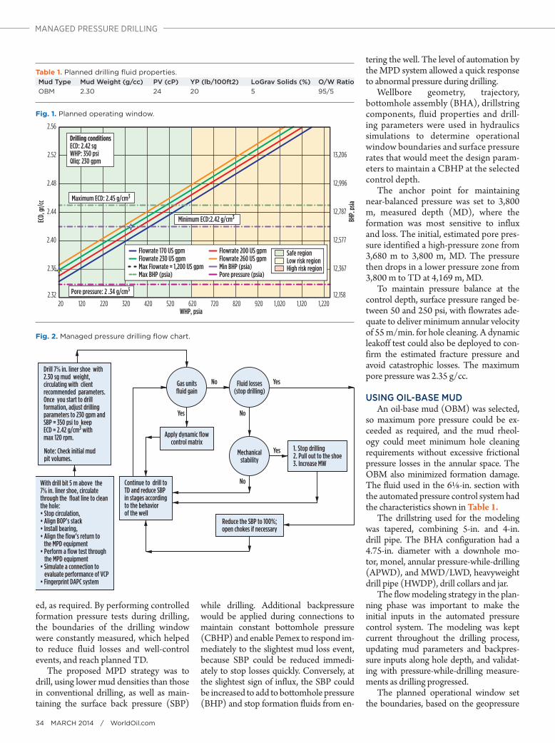
Table 1. Planned drilling fl uid properties. Mud Type Mud Weight (g/cc) PV (cP) YP (lb/100ft2) LoGrav Solids (%) O/W RatioOBM 2.30 24 20 5 95/5
Fig. 1. Planned operating window.
12,158
12,367
12,577
12,787
12,996
13,206
2.32
2.36
2.40
2.44
2.48
2.52
2.56
20 120 220 320 420 520 620 720 820 920 1,020 1,120 1,220
BHP,
psia
ECD,
gr/c
c
WHP, psia
Flowrate 170 US gpm Flowrate 200 US gpmFlowrate 230 US gpm Flowrate 260 US gpmMax Flowrate = 1,200 US gpm Min BHP (psia)Max BHP (psia) Pore pressure (psia)
Drilling conditions ECD: 2.42 sgWHP: 350 psiQliq: 230 gpm
Maximum ECD: 2.45 g/cm3
Minimum ECD:2.42 g/cm3
Pore pressure: 2 .34 g/cm3
Safe regionLow risk regionHigh risk region
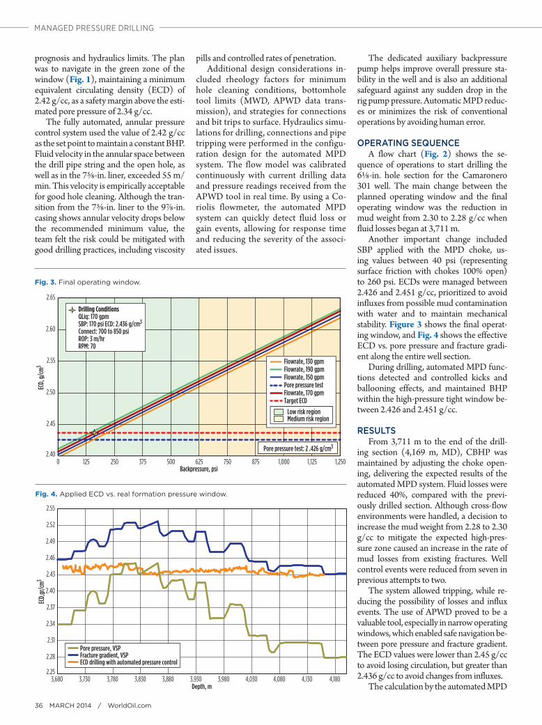
Fig. 2. Managed pressure drilling fl ow chart.
Drill 7⅝ in. liner shoe with2.30 sg mud weight,circulating with clientrecommended parameters.Once you start to drillformation, adjust drillingparameters to 230 gpm andSBP = 350 psi to keepECD = 2.42 g/cm3 withmax 120 rpm.
Note: Check initial mudpit volumes.
With drill bit 5 m above the7⅝ in. liner shoe, circulatethrough the float line to cleanthe hole:• Stop circulation,• Align BOP’s stack• Install bearing,• Align the flow’s return to the MPD equipment• Perform a flow test through the MPD equipment• Simulate a connection to evaluate performance of VCP• Fingerprint DAPC system
Continue to drill toTD and reduce SBPin stages accordingto the behaviorof the well
Reduce the SBP to 100%;open chokes if necessary
Apply dynamic flowcontrol matrix
1. Stop drilling2. Pull out to the shoe3. Increase MW
Fluid losses(stop drilling)
Gas unitsfluid gain
Mechanicalstability
No
Yes
Yes
Yes
No
No
36 MARCH 2014 / WorldOil.com
MANAGED PRESSURE DRILLING
prognosis and hydraulics limits. The plan was to navigate in the green zone of the window (Fig. 1), maintaining a minimum equivalent circulating density (ECD) of 2.42 g/cc, as a safety margin above the esti-mated pore pressure of 2.34 g/cc.
The fully automated, annular pressure control system used the value of 2.42 g/cc as the set point to maintain a constant BHP. Fluid velocity in the annular space between the drill pipe string and the open hole, as well as in the 7⅝-in. liner, exceeded 55 m/min. This velocity is empirically acceptable for good hole cleaning. Although the tran-sition from the 7⅝-in. liner to the 9⅞-in. casing shows annular velocity drops below the recommended minimum value, the team felt the risk could be mitigated with good drilling practices, including viscosity
pills and controlled rates of penetration.Additional design considerations in-
cluded rheology factors for minimum hole cleaning conditions, bottomhole tool limits (MWD, APWD data trans-mission), and strategies for connections and bit trips to surface. Hydraulics simu-lations for drilling, connections and pipe tripping were performed in the configu-ration design for the automated MPD system. The flow model was calibrated continuously with current drilling data and pressure readings received from the APWD tool in real time. By using a Co-riolis flowmeter, the automated MPD system can quickly detect fluid loss or gain events, allowing for response time and reducing the severity of the associ-ated issues.
The dedicated auxiliary backpressure pump helps improve overall pressure sta-bility in the well and is also an additional safeguard against any sudden drop in the rig pump pressure. Automatic MPD reduc-es or minimizes the risk of conventional operations by avoiding human error.
OPERATING SEQUENCEA flow chart (Fig. 2) shows the se-
quence of operations to start drilling the 6⅛-in. hole section for the Camaronero 301 well. The main change between the planned operating window and the final operating window was the reduction in mud weight from 2.30 to 2.28 g/cc when fluid losses began at 3,711 m.
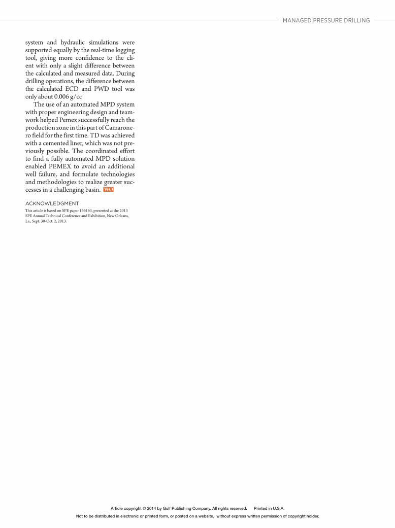
Another important change included SBP applied with the MPD choke, us-ing values between 40 psi (representing surface friction with chokes 100% open) to 260 psi. ECDs were managed between 2.426 and 2.451 g/cc, prioritized to avoid influxes from possible mud contamination with water and to maintain mechanical stability. Figure 3 shows the final operat-ing window, and Fig. 4 shows the effective ECD vs. pore pressure and fracture gradi-ent along the entire well section.
During drilling, automated MPD func-tions detected and controlled kicks and ballooning effects, and maintained BHP within the high-pressure tight window be-tween 2.426 and 2.451 g/cc.
RESULTSFrom 3,711 m to the end of the drill-
ing section (4,169 m, MD), CBHP was maintained by adjusting the choke open-ing, delivering the expected results of the automated MPD system. Fluid losses were reduced 40%, compared with the previ-ously drilled section. Although cross-flow environments were handled, a decision to increase the mud weight from 2.28 to 2.30 g/cc to mitigate the expected high-pres-sure zone caused an increase in the rate of mud losses from existing fractures. Well control events were reduced from seven in previous attempts to two.
The system allowed tripping, while re-ducing the possibility of losses and influx events. The use of APWD proved to be a valuable tool, especially in narrow operating windows, which enabled safe navigation be-tween pore pressure and fracture gradient. The ECD values were lower than 2.45 g/cc to avoid losing circulation, but greater than 2.436 g/cc to avoid changes from influxes.
The calculation by the automated MPD
Fig. 3. Final operating window.
2.40
2.45
2.50
2.55
2.60
2.65
0 125 250 375 500 625 750 875 1,000 1,125 1,250
Flowrate, 130 gpm
Flowrate, 150 gpm
Flowrate, 170 gpm
Flowrate, 190 gpm
Pore pressure test
Target ECD
Backpressure, psi
Drilling ConditionsQLiq: 170 gpmSBP: 170 psi ECD: 2.436 g/cm3
Connect: 700 to 850 psiROP: 3 m/hrRPM: 70
Low risk regionMedium risk region
ECD,
g/cm
3
Pore pressure test: 2 .426 g/cm3
Fig. 4. Applied ECD vs. real formation pressure window.
2.25
2.28
2.31
2.34
2.37
2.40
2.43
2.46
2.49
2.52
2.55
3,680 3,730 3,780 3,830 3,880 3,930 3,980 4,030 4,080 4,130 4,180
Pore pressure, VSPFracture gradient, VSPECD drilling with automated pressure control
Depth, m
ECD,
gr/cm
3
World Oil / MARCH 2014 37
MANAGED PRESSURE DRILLING
system and hydraulic simulations were supported equally by the real-time logging tool, giving more confidence to the cli-ent with only a slight difference between the calculated and measured data. During drilling operations, the difference between the calculated ECD and PWD tool was only about 0.006 g/cc
The use of an automated MPD system with proper engineering design and team-work helped Pemex successfully reach the production zone in this part of Camarone-ro field for the first time. TD was achieved with a cemented liner, which was not pre-viously possible. The coordinated effort to find a fully automated MPD solution enabled PEMEX to avoid an additional well failure, and formulate technologies and methodologies to realize greater suc-cesses in a challenging basin.
ACKNOWLEDGMENTThis article is based on SPE paper 166163, presented at the 2013 SPE Annual Technical Conference and Exhibition, New Orleans, La., Sept. 30-Oct. 2, 2013.
Article copyright © 2014 by Gulf Publishing Company. All rights reserved. Printed in U.S.A.
Not to be distributed in electronic or printed form, or posted on a website, without express written permission of copyright holder.