management component transport protocol (mctp) base … · 2017-12-28 · management component...
TRANSCRIPT
1
2
3
4
5
6
7
8
9
10
11
Document Number: DSP0236
Date: 2010-04-22
Version: 1.1.0
Management Component Transport Protocol (MCTP) Base Specification Includes MCTP Control Command Specifications
Document Type: Specification
Document Status: DMTF Standard
Document Language: en-US

MCTP Base Specification DSP0236
2 DMTF Standard Version 1.1.0
Copyright Notice 12
Copyright © 2009–2010 Distributed Management Task Force, Inc. (DMTF). All rights reserved. 13
14 15 16 17
18 19 20 21 22 23 24 25 26 27 28 29 30
31 32
DMTF is a not-for-profit association of industry members dedicated to promoting enterprise and systems management and interoperability. Members and non-members may reproduce DMTF specifications and documents, provided that correct attribution is given. As DMTF specifications may be revised from time to time, the particular version and release date should always be noted.
Implementation of certain elements of this standard or proposed standard may be subject to third party patent rights, including provisional patent rights (herein "patent rights"). DMTF makes no representations to users of the standard as to the existence of such rights, and is not responsible to recognize, disclose, or identify any or all such third party patent right, owners or claimants, nor for any incomplete or inaccurate identification or disclosure of such rights, owners or claimants. DMTF shall have no liability to any party, in any manner or circumstance, under any legal theory whatsoever, for failure to recognize, disclose, or identify any such third party patent rights, or for such party’s reliance on the standard or incorporation thereof in its product, protocols or testing procedures. DMTF shall have no liability to any party implementing such standard, whether such implementation is foreseeable or not, nor to any patent owner or claimant, and shall have no liability or responsibility for costs or losses incurred if a standard is withdrawn or modified after publication, and shall be indemnified and held harmless by any party implementing the standard from any and all claims of infringement by a patent owner for such implementations.
For information about patents held by third-parties which have notified the DMTF that, in their opinion, such patent may relate to or impact implementations of DMTF standards, visit http://www.dmtf.org/about/policies/disclosures.php. 33
34 35
36
37
PCI-SIG, PCIe, and the PCI HOT PLUG design mark are registered trademarks or service marks of PCI-SIG.
All other marks and brands are the property of their respective owners.

DSP0236 MCTP Base Specification
Version 1.1.0 DMTF Standard 3
CONTENTS 38
39 40 41 42 43 44 45 46 47 48 49 50 51 52 53 54 55 56 57 58 59 60 61 62 63 64 65 66 67 68 69 70 71 72 73 74 75 76 77 78 79 80 81 82 83 84 85 86 87 88 89
Foreword ....................................................................................................................................................... 7 Introduction ................................................................................................................................................... 8 1 Scope .................................................................................................................................................... 9 2 Normative References........................................................................................................................... 9 3 Terms and Definitions.......................................................................................................................... 10
3.1 Requirement Term Definitions .................................................................................................. 10 3.2 MCTP Term Definitions............................................................................................................. 12
4 Symbols and Abbreviated Terms......................................................................................................... 18 5 Conventions ........................................................................................................................................ 20
5.1 Byte Ordering............................................................................................................................ 20 5.2 Reserved Fields ........................................................................................................................ 20
6 Management Component Relationships ............................................................................................. 20 7 MCTP Overview .................................................................................................................................. 21 8 MCTP Base Protocol........................................................................................................................... 23
8.1 MCTP Packet Fields ................................................................................................................. 23 8.2 Special Endpoint IDs................................................................................................................. 26 8.3 Packet Payload and Transmission Unit Sizes .......................................................................... 26 8.4 Maximum Message Body Sizes................................................................................................ 27 8.5 Message Assembly................................................................................................................... 27 8.6 Dropped Packets ...................................................................................................................... 27 8.7 Starting Message Assembly ..................................................................................................... 28 8.8 Terminating Message Assembly/Dropped Messages .............................................................. 28 8.9 Dropped Messages................................................................................................................... 29 8.10 MCTP Versioning and Message Type Support ........................................................................ 29 8.11 MCTP Message Types ............................................................................................................. 30 8.12 Security ..................................................................................................................................... 30 8.13 Limitations................................................................................................................................. 30 8.14 MCTP Discovery and Addressing............................................................................................. 31 8.15 Devices with Multiple Media Interfaces..................................................................................... 32 8.16 Peer Transactions..................................................................................................................... 32 8.17 Endpoint ID Assignment and Endpoint ID Pools ...................................................................... 32 8.18 Handling Reassigned EIDs....................................................................................................... 37 8.19 MCTP Bridging.......................................................................................................................... 38 8.20 Bridge and Routing Table Examples ........................................................................................ 45 8.21 Endpoint ID Resolution ............................................................................................................. 49 8.22 Bridge and Bus Owner Implementation Recommendations..................................................... 51 8.23 Path and Transmission Unit Discovery..................................................................................... 52 8.24 Path Transmission Unit Requirements for Bridges................................................................... 55
9 MCTP Control Protocol ....................................................................................................................... 55 9.1 Terminology .............................................................................................................................. 55 9.2 MCTP Control Message Format ............................................................................................... 56 9.3 MCTP Control Message Fields................................................................................................. 56 9.4 MCTP Control Message Transmission Unit Size ..................................................................... 57 9.5 Tag Owner (TO), Request (Rq), and Datagram (D) Bit Usage................................................. 57 9.6 Concurrent Command Processing............................................................................................ 58
10 MCTP Control Messages .................................................................................................................... 59 10.1 MCTP Control Message Command Codes .............................................................................. 59 10.2 MCTP Control Message Completion Codes............................................................................. 61 10.3 Set Endpoint ID......................................................................................................................... 61 10.4 Get Endpoint ID ........................................................................................................................ 63 10.5 Get Endpoint UUID Command ................................................................................................. 64

MCTP Base Specification DSP0236
4 DMTF Standard Version 1.1.0
10.6 Get MCTP Version Support ...................................................................................................... 65 90 91 92 93 94 95 96 97 98 99
100 101 102 103 104 105 106 107 108 109 110
111
112 113 114 115 116 117 118 119 120 121 122 123 124 125 126 127 128 129 130 131 132 133
10.7 Get Message Type Support...................................................................................................... 67 10.8 Get Vendor Defined Message Support..................................................................................... 68 10.9 Resolve Endpoint ID ................................................................................................................. 69 10.10 Allocate Endpoint IDs................................................................................................................ 70 10.11 Routing Information Update...................................................................................................... 72 10.12 Get Routing Table Entries ........................................................................................................ 73 10.13 Prepare for Endpoint Discovery................................................................................................ 75 10.14 Endpoint Discovery................................................................................................................... 76 10.15 Discovery Notify ........................................................................................................................ 76 10.16 Query Hop................................................................................................................................. 76 10.17 Get Network ID Command........................................................................................................ 77 10.18 Transport Specific ..................................................................................................................... 78
11 Vendor Defined – PCI and Vendor Defined – IANA Messages .......................................................... 79 11.1 Vendor Defined – PCI Message Format................................................................................... 79 11.2 Vendor Defined – IANA Message Format ................................................................................ 79
ANNEX A (informative) Notation ................................................................................................................ 80 A.1 Notations................................................................................................................................... 80
ANNEX B (informative) Change Log......................................................................................................... 81 Bibliography ................................................................................................................................................ 82
Figures
Figure 1 – Management Component Relationships ................................................................................... 20 Figure 2 – MCTP Networks......................................................................................................................... 21 Figure 3 – MCTP Topology......................................................................................................................... 23 Figure 4 – Generic Message Fields ............................................................................................................ 23 Figure 5 – Topmost Bus Owners ................................................................................................................ 33 Figure 6 – Split Bridge................................................................................................................................. 34 Figure 7 – Acceptable Failover/Redundant Communication Topologies.................................................... 38 Figure 8 – Routing/Bridging Restrictions .................................................................................................... 39 Figure 9 – EID Options for MCTP Bridges.................................................................................................. 40 Figure 10 – Basic Routing Table Entry Fields............................................................................................. 43 Figure 11 – Routing Table Population ........................................................................................................ 44 Figure 12 – Example 1 Routing Topology................................................................................................... 46 Figure 13 – Example 2 Routing Topology................................................................................................... 47 Figure 14 – Example 3 Routing Topology................................................................................................... 48 Figure 15 – Endpoint ID Resolution ............................................................................................................ 50 Figure 16 – Resolving Multiple Paths ......................................................................................................... 51 Figure 17 – Example Path Routing Topology ............................................................................................. 53 Figure 18 – Path Transmission Unit Discovery Flowchart .......................................................................... 54 Figure 19 – MCTP Control Message Format .............................................................................................. 56 Figure 20 – Structure of Vendor ID Field for Get Vendor Defined Capabilities Message .......................... 69 Figure 21 – EID Pools from Multiple Bus Owners....................................................................................... 71

DSP0236 MCTP Base Specification
Version 1.1.0 DMTF Standard 5
Tables 134
135 136 137 138 139 140 141 142 143 144 145 146 147 148 149 150 151 152 153 154 155 156 157 158 159 160 161 162 163 164 165 166 167 168 169 170
Table 1 – MCTP Base Protocol Common Fields ........................................................................................ 24 Table 2 – Special Endpoint IDs................................................................................................................... 26 Table 3 – MCTP Message Types Used in this Specification ...................................................................... 30 Table 4 – Example 1 Routing Table for D2................................................................................................. 46 Table 5 – Example 2 Routing Table for D1................................................................................................. 47 Table 6 – Example 3 Routing Table for D2................................................................................................. 48 Table 7 – Additional Information Tracked by Bridges ................................................................................. 49 Table 8 – MCTP Control Protocol Terminology .......................................................................................... 55 Table 9 – MCTP Control Message Types................................................................................................... 55 Table 10 – MCTP Control Message Fields ................................................................................................. 56 Table 11 – Tag Owner (TO), Request (Rq) and Datagram (D) Bit Usage.................................................. 58 Table 12 – MCTP Control Command Numbers.......................................................................................... 59 Table 13 – MCTP Control Message Completion Codes............................................................................. 61 Table 14 – Set Endpoint ID Message ......................................................................................................... 62 Table 15 – Get Endpoint ID Message......................................................................................................... 63 Table 16 – Get Device UUID Message Format .......................................................................................... 65 Table 17 – Example UUID Format.............................................................................................................. 65 Table 18 – Get MCTP Version Support Message ...................................................................................... 66 Table 19 – Get Message Type Support Message ...................................................................................... 68 Table 20 – Get Vendor Defined Message Support Message ..................................................................... 68 Table 21 – Vendor ID Formats.................................................................................................................... 69 Table 22 – Resolve Endpoint ID Message.................................................................................................. 70 Table 23 – Allocate Endpoint IDs Message................................................................................................ 71 Table 24 – Routing Information Update Message ...................................................................................... 73 Table 25 – Routing Information Update Entry Format ................................................................................ 73 Table 26 – Get Routing Table Entries Message......................................................................................... 74 Table 27 – Routing Table Entry Format...................................................................................................... 74 Table 28 – Prepare for Endpoint Discovery Message ................................................................................ 75 Table 29 – Endpoint Discovery Message ................................................................................................... 76 Table 30 – Discovery Notify Message ........................................................................................................ 76 Table 31 – Query Hop Message ................................................................................................................. 77 Table 32 – Get Network ID Message Format ............................................................................................. 78 Table 33 – Transport Specific Message ..................................................................................................... 78 Table 34 – Vendor Defined – PCI Message Format................................................................................... 79 Table 35 – Vendor Defined – IANA Message Format ................................................................................ 79

MCTP Base Specification DSP0236
6 DMTF Standard Version 1.1.0
171

DSP0236 MCTP Base Specification
Version 1.1.0 DMTF Standard 7
Foreword 172
173 174
175 176
The Management Component Transport Protocol (MCTP) Base Specification (DSP0236) was prepared by the PMCI Working Group.
DMTF is a not-for-profit association of industry members dedicated to promoting enterprise and systems management and interoperability.

MCTP Base Specification DSP0236
8 DMTF Standard Version 1.1.0
Introduction 177
178 179
180
181
182 183
184 185 186 187 188
189 190 191 192
193 194 195
The Management Component Transport Protocol (MCTP) defines a communication model intended to facilitate communication between:
• Management controllers and other management controllers
• Management controllers and management devices
The communication model includes a message format, transport description, message exchange patterns, and configuration and initialization messages.
MCTP is designed so that it can potentially be used on many bus types. The protocol is intended to be used for intercommunication between elements of platform management subsystems used in computer systems, and is suitable for use in mobile, desktop, workstation, and server platforms. Management controllers such as a baseboard management controller (BMC) can use this protocol for communication between one another, as well as for accessing management devices within the platform.
Management controllers can use this protocol to send and receive MCTP-formatted messages across the different bus types that are used to access management devices and other management controllers. Management devices in a system need to provide an implementation of the message format to facilitate actions performed by management controllers.
It is intended that different types of devices in a management system may need to implement different portions of the complete capabilities defined by this protocol. Where relevant, this is called out in the individual requirements

DSP0236 MCTP Base Specification
Version 1.1.0 DMTF Standard 9
Management Component Transport Protocol (MCTP) Base Specification
196
197
199 200 201
202
203
204
205 206 207
1 Scope 198
The MCTP Base Specification describes the command protocol, requirements, and use cases of a transport protocol for communication between discrete management controllers on a platform, as well as between management controllers and the devices they manage.
This document is intended to meet the following objectives:
• Describe the MCTP Base transport protocol
• Describe the MCTP control message protocol
The MCTP specifies a transport protocol format. This protocol is independent of the underlying physical bus properties, as well as the "data-link" layer messaging used on the bus. The physical and data-link layer methods for MCTP communication across a given medium are defined by companion "transport binding" specifications, such as DSP0238, MCTP over PCIe® Vendor Defined Messaging, and DSP0237, MCTP over SMBus/ I
208 209 2C. This approach enables future transport bindings to be defined to support
DSP0237 additional buses such as USB, RMII, and others, without affecting the base MCTP specification.
210 211
213 214 215
216
2 Normative References 212
The following referenced documents are indispensable for the application of this document. For dated references, only the edition cited applies. For undated references, the latest edition of the referenced document (including any amendments) applies.
DMTF DSP0237, Management Component Transport Protocol (MCTP) SMBus/I2C Transport Binding Specification 1.0, http://www.dmtf.org/standards/published_documents/DSP0237_1.0.pdf 217
218 DMTF DSP0238, PCIe VDM Transport Binding Specification 1.0, http://www.dmtf.org/standards/published_documents/DSP0238_1.0.pdf 219
220 DMTF DSP0239, Management Component Transport Protocol (MCTP) IDs and Codes 1.0, http://www.dmtf.org/standards/published_documents/DSP0239_1.0.pdf 221
222 Hewlett-Packard, Intel, Microsoft, Phoenix, and Toshiba, Advanced Configuration and Power Interface Specification v3.0, ACPI, September 2, 2004, http://www.acpi.info/DOWNLOADS/ACPIspec30.zip 223
224 IETF, RFC4122, A Universally Unique Identifier (UUID) URN Namespace, July 2005, http://www.ietf.org/rfc/rfc4122.txt 225
226 Intel, Hewlett-Packard, NEC, and Dell, Intelligent Platform Management Interface Specification: Second Generation v2.0, IPMI, 2004, ftp://download.intel.com/design/servers/ipmi/IPMIv2_0rev1_0markup.pdf 227
228 ISO/IEC Directives, Part 2, Rules for the structure and drafting of International Standards, http://isotc.iso.org/livelink/livelink?func=ll&objId=4230456&objAction=browse&sort=subtype 229
OMG, Unified Modeling Language (UML) from the Open Management Group (OMG), http://www.uml.org 230

MCTP Base Specification DSP0236
10 DMTF Standard Version 1.1.0
PCI-SIG, PCI Express Base Specification v1.1, PCleV1.1, March 28, 2005, 231 http://www.pcisig.com/members/downloads/specifications/pciexpress/PCI_Express_Base_11.pdf 232
233 PCI-SIG, PCI Express Base Specification v2.0, PCleV2.0, December 20, 2006, http://www.pcisig.com/members/downloads/specifications/pciexpress/PCI_Express_Base_2.pdf 234
235
236
Philips Semiconductors, The I2C-Bus Specification v2.0, I2C, December 1998
SMBus, System Management Bus (SMBus) Specification v2.0, SMBus, 2000, http://www.smbus.org/specs/smbus20.pdf 237
239
241
243 244
246 247
249 250 251
253 254
256 257 258
260 261 262 263 264 265
267 268
3 Terms and Definitions 238
For the purposes of this document, the following terms and definitions apply.
3.1 Requirement Term Definitions 240
This clause defines key phrases and words that denote requirement levels in this specification.
3.1.1 242 can used for statements of possibility and capability, whether material, physical, or causal
3.1.2 245 cannot used for statements of possibility and capability, whether material, physical or causal
3.1.3 248 conditional indicates requirements to be followed strictly to conform to the document when the specified conditions are met
3.1.4 252 deprecated indicates that an element or profile behavior has been outdated by newer constructs
3.1.5 255 mandatory indicates requirements to be followed strictly to conform to the document and from which no deviation is permitted
3.1.6 259 may indicates a course of action permissible within the limits of the document NOTE: An implementation that does not include a particular option must be prepared to interoperate with another implementation that does include the option, although perhaps with reduced functionality. An implementation that does include a particular option must be prepared to interoperate with another implementation that does not include the option (except for the feature that the option provides).
3.1.7 266 may not indicates flexibility of choice with no implied preference

DSP0236 MCTP Base Specification
Version 1.1.0 DMTF Standard 11
3.1.8 269 must 270
271
273 274
276 277
279 280 281 282
284 285
287 288
290 291 292
294 295
297 298 299
301 302 303
305 306 307
309 310
indicates that the item is an absolute requirement of the specification
3.1.9 272 must not indicates that the definition is an absolute prohibition of the specification
3.1.10 275 need not indicates a course of action permissible within the limits of the document
3.1.11 278 not recommended indicates that valid reasons may exist in particular circumstances when the particular behavior is acceptable or even useful, but the full implications should be understood and carefully weighed before implementing any behavior described with this label
3.1.12 283 obsolete indicates that an item was defined in prior specifications but has been removed from this specification
3.1.13 286 optional indicates a course of action permissible within the limits of the document
3.1.14 289 recommended indicates that valid reasons may exist in particular circumstances to ignore a particular item, but the full implications should be understood and carefully weighed before choosing a different course
3.1.15 293 required indicates that the item is an absolute requirement of the specification
3.1.16 296 shall indicates requirements to be followed strictly to conform to the document and from which no deviation is permitted
3.1.17 300 shall not indicates requirements to be followed strictly to conform to the document and from which no deviation is permitted
3.1.18 304 should indicates that among several possibilities, one is recommended as particularly suitable, without mentioning or excluding others, or that a certain course of action is preferred but not necessarily required
3.1.19 308 should not indicates that a certain possibility or course of action is deprecated but not prohibited

MCTP Base Specification DSP0236
12 DMTF Standard Version 1.1.0
3.2 MCTP Term Definitions 311
For the purposes of this document, the following terms and definitions apply. 312
314 315 316 317
319 320 321 322
324 325 326 327 328 329
331 332 333 334 335 336 337 338 339 340
342 343 344 345
347 348 349
351 352 353 354 355
3.2.1 313 Address Resolution Protocol ARP refers to the procedure used to dynamically determine the addresses of devices on a shared communication medium
3.2.2 318 baseline transmission unit the required common denominator size of a transmission unit for packet payloads that are carried in an MCTP packet. Baseline Transmission Unit-sized packets are guaranteed to be routable within an MCTP network.
3.2.3 323 baseboard management controller BMC a term coined by the IPMI specifications for the main management controller in an IPMI-based platform management subsystem. Also sometimes used as a generic name for a motherboard resident management controller that provides motherboard-specific hardware monitoring and control functions for the platform management subsystem.
3.2.4 330 binary-coded decimal BCD indicates a particular binary encoding for decimal numbers where each four bits (nibble) in a binary number is used to represent a single decimal digit, and with the least significant four bits of the binary number corresponding to the least significant decimal digit. The binary values 0000b through 1001b represent decimal values 0 through 9, respectively. For example, with BCD encoding a byte can represent a two-digit decimal number where the most significant nibble (bits 7:4) of the byte contains the encoding for the most significant decimal digit and the least significant nibble (bits 3:0) contains the encoding for the least significant decimal digit (for example, 0010_1001b in BCD encoding corresponds to the decimal number 29).
3.2.5 341 bridge generically, the circuitry and logic that connects one computer bus or interconnect to another, allowing an agent on one to access the other. Within this document, the term bridge shall refer to MCTP bridge, unless otherwise indicated.
3.2.6 346 bus a physical addressing domain shared between one or more platform components that share a common physical layer address space
3.2.7 350 bus owner the party responsible for managing address assignments (can be logical or physical addresses) on a bus (for example, in MCTP, the bus owner is the party responsible for managing EID assignments for a given bus). A bus owner may also have additional media-specific responsibilities, such as assignment of physical addresses.

DSP0236 MCTP Base Specification
Version 1.1.0 DMTF Standard 13
3.2.8 356 byte 357
358 359
361
an 8-bit quantity. Also referred to as an octet. NOTE: PMCI specifications shall use the term byte, not octet.
3.2.9 360 endpoint see MCTP endpoint 362
364 365
3.2.10 363 endpoint ID EID see MCTP endpoint ID 366
368 369
3.2.11 367 Globally Unique Identifier GUID see UUID 370
372
373 374
376 377 378
380 381 382 383 384
386 387 388 389
391 392 393 394
3.2.12 371 host interface
a hardware interface and associated protocols that is used by software running locally on the host processors to access the hardware of a management subsystem within a managed system.
3.2.13 375 Inter-Integrated Circuit I2C a multi-master, two-wire, serial bus originally developed by Philips Semiconductor
3.2.14 379 intelligent management device IMD a management device that is typically implemented using a microcontroller and accessed through a messaging protocol. Management parameter access provided by an IMD is typically accomplished using an abstracted interface and data model rather than through direct "register level" accesses.
3.2.15 385 Intelligent Platform Management Bus IPMB name for the architecture, protocol, and implementation of an I2C bus that provides a communications path between "management controllers" in IPMI -based systems
3.2.16 390 Intelligent Platform Management Interface IPMI a set of specifications defining interfaces and protocols originally developed for server platform management by the IPMI Promoters Group: Intel, Dell, HP, and NEC

MCTP Base Specification DSP0236
14 DMTF Standard Version 1.1.0
3.2.17 395 managed entity 396
397 398 399
401 402 403
405 406 407 408 409 410 411 412 413
415 416 417 418 419 420 421 422
424 425 426 427
429 430 431 432
434 435 436 437 438
the physical or logical entity that is being managed through management parameters. Examples of physical entities include fans, processors, power supplies, circuit cards, chassis, and so on. Examples of logical entities include virtual processors, cooling domains, system security states, and so on.
3.2.18 400 Management Component Transport Protocol MCTP The protocol defined in this specification.
3.2.19 404 management controller a microcontroller or processor that aggregates management parameters from one or more management devices and makes access to those parameters available to local or remote software, or to other management controllers, through one or more management data models. Management controllers may also interpret and process management-related data, and initiate management-related actions on management devices. While a native data model is defined for PMCI, it is designed to be capable of supporting other data models, such as CIM, IPMI, and vendor-specific data models. The microcontroller or processor that serves as a management controller can also incorporate the functions of a management device.
3.2.20 414 management device any physical device that provides protocol terminus for accessing one or more management parameters. A management device responds to management requests, but does not initiate or aggregate management operations except in conjunction with a management controller (that is, it is a satellite device that is subsidiary to one or more management controllers). An example of a simple management device would be a temperature sensor chip. A management controller that has I/O pins or built-in analog-to-digital converters that monitor state and voltages for a managed entity would also be a management device.
3.2.21 423 management parameter a particular datum representing a characteristic, capability, status, or control point associated with a managed entity. Example management parameters include temperature, speed, volts, on/off, link state, uncorrectable error count, device power state, and so on.
3.2.22 428 MCTP bridge an MCTP endpoint that can route MCTP messages not destined for itself that it receives on one interconnect onto another without interpreting them. The ingress and egress media at the bridge may be either homogeneous or heterogeneous. Also referred to in this document as a "bridge".
3.2.23 433 MCTP bus owner responsible for EID assignment for MCTP or translation on the buses that it is a master of. The MCTP bus owner may also be responsible for physical address assignment. For example, for SMBus bus segments, the MCTP bus owner is also the ARP master. This means the bus owner assigns dynamic SMBus addresses to those devices requiring it.

DSP0236 MCTP Base Specification
Version 1.1.0 DMTF Standard 15
3.2.24 439 MCTP control command 440
441 442 443
445 446 447 448 449
451 452 453 454 455 456 457
459 460
462 463 464
466 467 468
470 471 472
474 475 476
478 479
481 482
commands defined under the MCTP control message type that are used for the initialization and management of MCTP communications (for example, commands to assign EIDs, discover device MCTP capabilities, and so on)
3.2.25 444 MCTP endpoint an MCTP communication terminus. An MCTP endpoint is a terminus or origin of MCTP packets or messages. That is, the combined functionality within a physical device that communicates using the MCTP transport protocol and handles MCTP control commands. This includes MCTP-capable management controllers and management devices. Also referred to in this document as "endpoint".
3.2.26 450 MCTP endpoint ID the logical address used to route MCTP messages to a specific MCTP endpoint. A numeric handle (logical address) that uniquely identifies a particular MCTP endpoint within a system for MCTP communication and message routing purposes. Endpoint IDs are unique among MCTP endpoints that comprise an MCTP communication network within a system. MCTP EIDs are only unique within a particular MCTP network. That is, they can be duplicated or overlap from one MCTP network to the next. Also referred to in this document as "endpoint ID" and abbreviated "EID".
3.2.27 458 MCTP host interface a host interface that enables host software to locally access an MCTP Network in the managed system.
3.2.28 461 MCTP management controller a management controller that is an MCTP endpoint. Unless otherwise indicated, the term "management controller" refers to an "MCTP management controller" in this document.
3.2.29 465 MCTP management device a management device that is an MCTP endpoint. Unless otherwise indicated, the term "management device" refers to an "MCTP management device" in this document.
3.2.30 469 MCTP message a unit of communication based on the message type that is relayed through the MCTP Network using one or more MCTP packets
3.2.31 473 MCTP network a collection of MCTP endpoints that communicate using MCTP and share a common MCTP endpoint ID space
3.2.32 477 MCTP network ID a unique identifier to distinguish each independent MCTP network within a platform
3.2.33 480 MCTP packet the unit of data transfer used for MCTP communication on a given physical medium

MCTP Base Specification DSP0236
16 DMTF Standard Version 1.1.0
3.2.34 483 MCTP packet payload 484
485
487
refers to the portion of the message body of an MCTP message that is carried in a single MCTP packet
3.2.35 486 message see MCTP message 488
490 491 492
494 495 496 497 498
500 501 502 503
505 506
508 509 510 511 512
514 515 516
518 519
521
3.2.36 489 message assembly the process of receiving and linking together two or more MCTP packets that belong to a given MCTP message to allow the entire message header and message data (payload) to be extracted
3.2.37 493 message body the portion of an MCTP message that carries the message type field and any message type-specific data associated with the message. An MCTP message spans multiple MCTP packets when the message body needs is larger than what can fit in a single MCTP packet. Thus, the message body portion of an MCTP message can span multiple MCTP packets.
3.2.38 499 message disassembly the process of taking an MCTP message where the message's header and data (payload) cannot be carried in a single MCTP packet and generating the sequence of two or more packets required to deliver that message content within the MCTP network
3.2.39 504 message originator the original transmitter (source) of a message targeted to a particular message terminus
3.2.40 507 message terminus the name for a triplet of fields called the MCTP Source Endpoint ID, Tag Owner bit value, and Message Tag value. Together, these fields identify the packets for an MCTP message within an MCTP network for the purpose of message assembly. The message terminus itself can be thought of as identifying a set of resources within the recipient endpoint that is handling the assembly of a particular message.
3.2.41 513 most significant byte MSB refers to the highest order byte in a number consisting of multiple bytes
3.2.42 517 nibble the computer term for a four-bit aggregation, or half of a byte
3.2.43 520 packet see MCTP packet 522
524 3.2.44 523 packet payload see MCTP packet payload 525

DSP0236 MCTP Base Specification
Version 1.1.0 DMTF Standard 17
3.2.45 526 pass-through traffic/message/packets 527
528 529
531 532 533 534
536 537 538 539
541 542 543 544 545 546
548 549 550
552 553 554 555 556
558 559 560
562 563 564
566
non-control packets passed between the external network and the management controller through the network controller
3.2.46 530 payload refers to the information bearing fields of a message. This is separate from those fields and elements that are used to transport the message from one point to another, such as address fields, framing bits, checksums, and so on. In some instances, a given field may be both a payload field and a transport field.
3.2.47 535 physical transport binding refers to specifications that define how the MCTP base protocol and MCTP control commands are implemented on a particular physical transport type and medium, such as SMBus/I2C, PCI Express™ Vendor Defined Messaging, and so on.
3.2.48 540 Platform Management Component Intercommunications PMCI name for a working group under the Distributed Management Task Force's Pre-OS Workgroup that is chartered to define standardized communication protocols, low level data models, and transport definitions that support communications with and between management controllers and management devices that form a platform management subsystem within a managed computer system
3.2.49 547 point-to-point refers to the case where only two physical communication devices are interconnected through a physical communication medium. The devices may be in a master/slave relationship, or could be peers.
3.2.50 551 Reduced Media Independent Interface RMII a reduced signal count MAC to PHY interface, based on the IEEE Media Independent Interface (MII), which was specified by the RMII Consortium (3Com Corporation; AMD Inc.; Bay Networks, Inc.; Broadcom Corp.; National Semiconductor Corp.; and Texas Instruments Inc.)
3.2.51 557 simple endpoint an MCTP endpoint that is not associated with either the functions of an MCTP bus owner or an MCTP bridge
3.2.52 561 Transmission Unit refers to the size of the portion of the MCTP packet payload, which is the portion of the message body carried in an MCTP packet
3.2.53 565 transport binding see physical transport binding 567

MCTP Base Specification DSP0236
18 DMTF Standard Version 1.1.0
3.2.54 568 Universally Unique Identifier 569
570 571 572 573
UUID refers to an identifier originally standardized by the Open Software Foundation (OSF) as part of the Distributed Computing Environment (DCE). UUIDs are created using a set of algorithms that enables them to be independently generated by different parties without requiring that the parties coordinate to ensure that generated IDs do not overlap. In this specification, RFC4122 is used as the base specification describing the format and generation of UUIDs. Also sometimes referred to as a globally unique identifier (GUID).
574 575 576
578
580 581
583 584
586 587
589 590
592 593
595 596
598 599
601 602
604 605
607 608
4 Symbols and Abbreviated Terms 577
The following symbols and abbreviations are used in this document.
4.1 579 ACPI Advanced Configuration and Power Interface
4.2 582 ARP Address Resolution Protocol
4.3 585 BCD binary-coded decimal
4.4 588 BMC baseboard management controller
4.5 591 CIM Common Information Model
4.6 594 EID endpoint identifier
4.7 597 FIFO first-in first-out
4.8 600 GUID Globally Unique Identifier
4.9 603 I2C Inter-Integrated Circuit
4.10 606 IANA Internet Assigned Numbers Authority

DSP0236 MCTP Base Specification
Version 1.1.0 DMTF Standard 19
4.11 609 IMD 610
611
613 614
616 617
619 620
622 623
625 626
628 629
631 632
634 635
637 638
640 641
643 644
646 647
intelligent management device
4.12 612 IP Internet Protocol
4.13 615 IPMB Intelligent platform management bus
4.14 618 IPMI Intelligent platform management interface
4.15 621 ISO/IEC International Organization for Standardization/International Engineering Consortium
4.16 624 KCS Keyboard Controller Style
4.17 627 MCTP Management Component Transport Protocol
4.18 630 MSB most significant byte
4.19 633 PCIe Peripheral Component Interconnect (PCI) Express
4.20 636 PMCI Platform Management Component Intercommunications
4.21 639 RMII Reduced Media Independent Interface
4.22 642 SMBus System Management Bus
4.23 645 TCP/IP Transmission Control Protocol/Internet Protocol

MCTP Base Specification DSP0236
20 DMTF Standard Version 1.1.0
4.24 648 USB 649
650
652 653
655 656
658
660 661
663 664
665 666
668 669
Universal Serial Bus
4.25 651 UUID Universally Unique Identifier
4.26 654 VDM Vendor Defined Message
5 Conventions 657
The conventions described in the following clauses apply to this specification.
5.1 Byte Ordering 659
Unless otherwise specified, byte ordering of multi-byte numeric fields or bit fields is "Big Endian" (that is, the lower byte offset holds the most significant byte, and higher offsets hold lesser significant bytes).
5.2 Reserved Fields 662
Unless otherwise specified, any reserved, unspecified, or unassigned values in enumerations or other numeric ranges are reserved for future definition by the DMTF.
Unless otherwise specified, numeric or bit fields that are designated as reserved shall be written as 0 (zero) and ignored when read.
6 Management Component Relationships 667
Figure 1 illustrates the relationship between devices, management controllers, management devices, and managed entities, which are described in Clause 3.2.
670
671 Figure 1 – Management Component Relationships

DSP0236 MCTP Base Specification
Version 1.1.0 DMTF Standard 21
7 MCTP Overview 672
This clause provides an overview of the main elements of MCTP. Additional overview information is available in the MCTP white paper,
673 DSP2016. 674
675 676 677 678 679 680
681 682 683 684
685 686 687
688 689 690 691 692
693 694 695
MCTP is a transport independent protocol that is used for intercommunication within an MCTP Network. An MCTP Network that consists of one of more physical transports that are used to transfer MCTP Packets between MCTP Endpoints. MCTP Transport Binding Specifications define how the MCTP protocol is implemented across a particular physical transport medium. For example, the DMTF has defined transport bindings for MCTP over SMBus/I2C and MCTP over PCIe using PCIe Vendor Defined Messages (VDMs), and others.
An MCTP Endpoint is the terminus for MCTP communication. A physical device that supports MCTP may provide one or more MCTP Endpoints. Endpoints are addressed using a logical address called the Endpoint ID, or EID. EIDs in MCTP are analogous to IP Addresses in Internet Protocol networking. EIDs can be statically or dynamically allocated.
A system implementation can contain multiple MCTP Networks. Each MCTP Network has its own separate EID space. There is no coordination of EIDs between MCTP Networks. EIDs can overlap between MCTP Networks.
An MCTP Network may provide an MCTP Network ID that can be used to differentiate different MCTP Networks when more than one MCTP Network can be accessed by an entity such as system software. The Network ID is also used when an entity has more than one point of access to the MCTP Network. In this case, the MCTP Network ID enables the entity to tell whether the access points provide access to the same MCTP Network or to different MCTP Networks.
MCTP also includes the definition of MCTP host interfaces. MCTP host interfaces are used by software that runs locally on the host processors of the managed system to access an MCTP Network.
IMDon motherboard
MCon motherboard
PCIe Card 1
LAN
PCIe Card 2
Module
MCTPhost i/f
MCTP over PCIe VDM
MCTP over PCIe VDM
MCTP over PCIe VDM
MAP MCEID “Y”
IMDEID “X”
MCTPhost i/f
EID “A” EID “B”
MCEID “R”
IMDEID “S”
MCTPhost i/f
MCEID “Y”
IMDEID “Z”
PCIePCIe VDMs
Network B
Network ANetwork C
696
697 Figure 2 – MCTP Networks

MCTP Base Specification DSP0236
22 DMTF Standard Version 1.1.0
Figure 2 shows the different ways MCTP Networks can exist in a system. In this example, Network A connects a Management Controller (MC) and Intelligent Management Device (IMD) on a motherboard with devices on PCIe Card 1 using MCTP over PCIe Vendor Defined Messages. Note that there are two host interfaces (host i/f) on standard PCIe that can be used by host software to access this particular network. This network thus requires an MCTP Network ID so that the host software can tell that the two host interfaces connect to the same MCTP Network.
698 699 700 701 702 703
704 705 706
707 708 709
710 711 712
713 714 715 716 717 718 719 720
Network B represents a network that is solely used for interconnecting devices within PCIe Card 2. This MCTP Network would typically not require an MCTP Network ID since it is not visible to host software or any other entity that would needs to differentiate Network B from another MCTP Network in the system.
Network C represents an MCTP Network on an add-in module. This network is separate from networks A and B but can be accessed by host software through PCIe. Thus, this network requires a Network ID so that host software can differentiate that Network C is a different network than Network A.
MCTP Messages are comprised of one or more MCTP Packets. MCTP defines fields that support the assembly of received MCTP Packets into MCTP Messages and the disassembly of MCTP Messages into packets for transmission.
MCTP is designed to be able to transfer multiple Message Types in an interleaved manner using the same protocol. MCTP Message Types identified using a Message Type number. The use of the message type number is similar to a well-known port number in Internet Protocol. It identifies MCTP Messages that are all associated with a particular specification. This specification defines a Message Type for MCTP Control Messages that are used to initialize and maintain the MCTP Network. The DMTF has also defined Message Types for use by the PMCI (Platform Management Communications Interconnect) specifications, Vendor-specific Messaging over MCTP, and so on. Additional message types for functions such as implementing NC-SI (network controller sideband interface) communications over MCTP and others are expected in the future. MCTP Message Type number assignments are provided in DSP0239. 721
722 723 724 725
726 727 728 729 730
731 732 733
734 735 736
MCTP Control Messages use a request/response protocol. It is important to note that the base transport protocol defined by MCTP just defines a protocol for the transport of MCTP messages. Whether the message content is a request, a response, or something else is part of the particular Message Type definition.
In MCTP, a Bus is defined as a physical medium that shares a single physical address space. MCTP includes the definition of a function called the MCTP Bus Owner. The Bus Owner provides to main functions. It distributes EIDs to Endpoints when the MCTP implementation uses EIDs that are dynamically allocated, and it provides the way for an Endpoint to resolve an EID into the physical address used that is required to deliver a message to the target Endpoint.
Busses can be interconnected within an MCTP Network using MCTP Bridges to forward MCTP packets between busses. Bridges also handle the task of managing the difference in moving packets from one type of physical media to another, such as moving an MCTP packet between SMBus and PCIe.
The following example illustrates how MCTP can be used within a hypothetical platform management subsystem implementation. More complex topologies, with multi-levels of bridges and greater numbers of busses and devices can be readily supported by MCTP as required.

DSP0236 MCTP Base Specification
Version 1.1.0 DMTF Standard 23
737
738
740
741 742 743 744 745
747
Figure 3 – MCTP Topology
8 MCTP Base Protocol 739
The MCTP base protocol defines the common fields for MCTP packets and messages and their usage.
Though there are medium-specific packet header fields and trailer fields, the fields for the base protocol are common for all media. These common fields support the routing and transport of messages between MCTP endpoints and the assembly and disassembly of large messages from and into multiple MCTP packets, respectively. The base protocol’s common fields include a message type field that identifies what particular higher layer class of message is being carried using the MCTP base protocol.
8.1 MCTP Packet Fields 746
Figure 4 shows the fields that constitute a generic MCTP packet.
748
749 Figure 4 – Generic Message Fields

MCTP Base Specification DSP0236
24 DMTF Standard Version 1.1.0
Table 1 defines the base protocol common fields. 750
751 Table 1 – MCTP Base Protocol Common Fields
Field Name Field Size Description
Medium-specific header
see description
This field represents the physical addressing and framing information that is used for transferring MCTP packets between devices on a particular physical medium. The size and type of any sub-fields or data within this field are defined by the corresponding transport binding specification for MCTP messaging on a given medium (for example, MCTP over SMBus, MCTP over PCIe, and so on).
Medium-specific trailer
see description
This field represents any additional medium-specific trailer fields (if any) that are required for transferring MCTP packets between devices on a particular physical medium. A typical use of this field would be to hold per-packet data integrity fields (for example CRC, checksum, and so on) that would be specified for the particular medium.
MCTP transport header
32 bits The MCTP transport header is part of each MCTP packet and provides version and addressing information for the packet as well as flags and a "Message Tag" field that, in conjunction with the source EID, is used to identify packets that constitute an MCTP message. The MCTP transport header fields are common fields that are always present regardless of the physical medium over which MCTP is being used.
Note: The positioning of the sub-fields of the MCTP transport header may vary based on the physical medium binding.
RSVD 4 bits (Reserved) Reserved for future definition by the MCTP base specification.
Hdr version 4 bits (Header version) Identifies the format, physical framing, and data integrity mechanism used to transfer the MCTP common fields in messages on a given physical medium. The value is defined in the specifications for the particular medium.
Note: The value in this field can vary between different transport bindings.
Destination endpoint ID
8 bits The EID for the endpoint to receive the MCTP packet.
A few EID values are reserved for specific routing.
See Table 2 – Special Endpoint IDs.
Source endpoint ID
8 bits The EID of the originator of the MCTP packet. See Table 2 – Special Endpoint IDs.
SOM 1 bit (Start Of Message) Set to 1b if this packet is the first packet of a message.
EOM 1 bit (End Of Message) Set to 1b if this packet is the last packet of a message.
Pkt Seq # 2 bits (Packet sequence number) For messages that span multiple packets, the packet sequence number increments modulo 4 on each successive packet. This allows the receiver to detect up to three successive missing packets between the start and end of a message. Though the packet sequence number can be any value (0-3) if the SOM bit is set, it is recommended that it is an increment modulo 4 from the prior packet with an EOM bit set. After the SOM packet, the packet sequence number must increment modulo 4 for each subsequent packet belonging to a given message up through the packet containing the EOM flag.

DSP0236 MCTP Base Specification
Version 1.1.0 DMTF Standard 25
Field Name Field Size Description
Msg tag 3 bits (Message tag) Field that, along with the Source Endpoint IDs and the Tag Owner (TO) field, identifies a unique message at the MCTP transport level. Whether other elements, such as portions of the MCTP Message Data field, are also used for uniquely identifying instances or tracking retries of a message is dependent on the message type.
A source endpoint is allowed to interleave packets from multiple messages to the same destination endpoint concurrently, provided that each of the messages has a unique message tag.
For messages that are split up into multiple packets, the Tag Owner (TO) and Message Tag bits remain the same for all packets from the SOM through the EOM.
TO 1 bit The TO (Tag Owner) bit identifies whether the message tag was originated by the endpoint that is the source of the message or by the endpoint that is the destination of the message. The Message Tag field is generated and tracked independently for each value of the Tag Owner bit. MCTP message types may overlay this bit with additional meaning, for example using it to differentiate between "request" messages and "response" messages.
Set to 1b to indicate that the source of the message originated the message tag.
Message body See description
The message body represents the payload of an MCTP message. The message body can span multiple MCTP packets.
IC 1 bit (MCTP integrity check bit) Indicates whether the MCTP message is covered by an overall MCTP message payload integrity check. This field is required to be the most significant bit of the first byte of the message body in the first packet of a message along with the message type bits.
0b = No MCTP message integrity check
1b = MCTP message integrity check is present
Message type 7 bits Defines the type of payload contained in the message data portion of the MCTP message. This field is required to be contained in the least-significant bits of the first byte of the message body in the first packet of a message. Like the fields in the MCTP transport header, the message type field is one of the common MCTP fields that are present independent of the transport over which MCTP is being used. Unlike the MCTP transport header, however, the message type field is only required to be present in the first packet of a particular MCTP message, whereas the MCTP transport header fields are present in every MCTP packet.
Message header 0 to M bytes Additional header information associated with a particular message type, if any. This will typically only be contained in the first packet of a message, but a given message type definition can define header fields as required for any packet.
Message data 0 to N bytes Data associated with the particular message type. Defined according to the specifications for the message type.
MCTP packet payload
See description
The packet payload is the portion of the message body that is carried in a given MCTP packet. The packet payload is limited according to the rules governing packet payload and transfer unit sizes. See 8.3 for more information.

MCTP Base Specification DSP0236
26 DMTF Standard Version 1.1.0
Field Name Field Size Description
Msg integrity check
Message type-specific
(MCTP message integrity check) This field represents the optional presence of a message type-specific integrity check over the contents of the message body. If present, the Message integrity check field must be carried in the last bytes of the message body. The particular message type definition will specify whether this is required, optional, or not to be used, the field size, and what algorithm is to be used to generate the field. The MCTP base protocol does not specify whether this field is required on single packet messages (potentially dependent on transmission unit size) or is only required on multiple packet messages. This is left to the message type specification.
8.2 Special Endpoint IDs 752
Table 2 lists EID values that are reserved or assigned to specific functions for MCTP. 753
754 Table 2 – Special Endpoint IDs
Value Description
Destination endpoint ID 0 Null Destination EID. This value indicates that the destination EID value is to be ignored and that only physical addressing is used to route the message to the destination on the given bus. This enables communication with devices that have not been assigned an EID. Because the physical addresses between buses are not guaranteed to be unique, MCTP does not support bridging messages with a null destination EID between different buses.
Source endpoint ID 0 Null Source EID. This value indicates a message is coming from an endpoint that is using physical addressing only. This would typically be used for messages that are delivered from an endpoint that has not been assigned an EID. Because the physical addresses between buses are not guaranteed to be unique, MCTP does not support bridging messages with a null source EID between different buses.
Endpoint IDs 1 through 7 Reserved for future definition.
Endpoint ID 0xFF Broadcast EID. Reserved for use as a broadcast EID on a given bus. MCTP network-wide broadcasts are not supported. Primarily for use by the MCTP control message type.
All other values Available for assignment and allocation to endpoints.
8.3 Packet Payload and Transmission Unit Sizes 755
For MCTP, the size of a transmission unit is defined as the size of the packet payload that is carried in an MCTP packet.
756 757
759
760
761 762 763
764 765 766
8.3.1 Baseline Transmission Unit 758
The following are key information points regarding baseline transmission unit:
• The baseline transmission unit (minimum transmission unit) size for MCTP is 64 bytes.
• A message terminus that supports MCTP control messages must always accept valid packets that have a transmission unit equal to or less than the baseline transmission unit. The message terminus is also allowed to support larger transmission units.
• The transmission unit of all packets in a given message must be the same size, except for the transmission unit in the last packet (packet with EOM bit = 1b). Except for the last packet, this size must be at least the baseline transmission unit size.

DSP0236 MCTP Base Specification
Version 1.1.0 DMTF Standard 27
• The size of the transmission unit in the last packet must be less than or equal to the transmission unit size used for the other packets (if any).
767 768
769 770 771 772
773 774
775 776 777 778
780 781
783 784
785
786
787
788 789
791 792 793
794
795 796 797 798
799
800 801 802
803
804 805 806
• If a transmission unit size larger than the baseline transmission unit is negotiated, the transmission unit of all packets must be less than or equal to the negotiated transmission unit size. (The negotiation mechanism for larger transmission units between endpoints is message type-specific and is not addressed in this specification.)
• A given endpoint may negotiate additional restrictions on packet sizes for communication with another endpoint, as long as the requirements of this section are met.
• All message types must include support for being delivered using packets that have a transmission unit that is no larger than the baseline transmission unit. This is required to support bridging those messages in implementations where there are MCTP bridges that only support the baseline transmission unit.
8.4 Maximum Message Body Sizes 779
The Message Body can span multiple packets. Limitations on message body sizes are message type-specific and are documented in the specifications for each message type.
8.5 Message Assembly 782
The following fields (and only these fields) are collectively used to identify the packets that belong to a given message for the purpose of message assembly on a particular destination endpoint.
• Msg Tag (Message Tag)
• TO (Tag Owner)
• Source Endpoint ID
As described in 3.2, together these values identify the message terminus on the destination endpoint. For a given message terminus, only one message assembly is allowed to be in process at a time.
8.6 Dropped Packets 790
Individual packets are dropped (silently discarded) by an endpoint under the following conditions. These packets are discarded before being checked for acceptance or rejection for message assembly. Therefore, these packets will not cause a message assembly to be started or terminated.
• Unexpected "middle" packet or "end" packet
A "middle" packet (SOM flag = 0 and EOM flag = 0) or "end" packet (SOM flag = 0 and EOM flag = 1) for a multiple-packet message is received for a given message terminus without first having received a corresponding "start" packet (where the "start" packet has SOM flag = 1 and EOM flag = 0) for the message.
• Bad packet data integrity or other physical layer error
A packet is dropped at the physical data-link layer because a data integrity check on the packet at that layer was invalid. Other possible physical layer errors may include framing errors, byte alignment errors, packet sizes that do not meet the physical layer requirements, and so on.
• Bad, unexpected, or expired message tag
A message with TO bit = 0 was received, indicating that the destination endpoint was the originator of the tag value, but the destination endpoint did not originate that value, or is no longer expecting it. (MCTP bridges do not check message tag or TO bit values for messages

MCTP Base Specification DSP0236
28 DMTF Standard Version 1.1.0
that are not addressed to the bridge’s EID, or to the bridge’s physical address if null-source or destination-EID physical addressing is used.)
807 808
809
810 811
812
813 814
815
816
817
818
820 821
822 823
824 825
827 828
829
830 831 832 833 834
835
836 837 838 839 840
841
842 843 844
• Unknown destination EID
A packet is received at the physical address of the device, but the destination EID does not match the EID for the device or the EID is un-routable.
• Un-routable EID
An MCTP bridge receives an EID that the bridge is not able to route (for example, because the bridge did not have a routing table entry for the given endpoint).
• Bad header version
The MCTP header version (Hdr Version) value is not a value that the endpoint supports.
• Unsupported transmission unit
The transmission unit size is not supported by the endpoint that is receiving the packet.
8.7 Starting Message Assembly 819
Multiple-packet message assembly begins when the endpoint corresponding to the destination EID in the packet receives a valid "start" packet (packet with SOM = 1b and EOM = 0b).
A packet with both SOM = 1b and EOM = 1b is considered to be a single-packet message, and is not assembled per se.
Both multiple- and single-packet messages are subject to being terminated or dropped based on conditions listed in the following section.
8.8 Terminating Message Assembly/Dropped Messages 826
Message assembly is terminated at the destination endpoint and messages are accepted or dropped under the following conditions:
• Receipt of the "end" packet for the given message
Receiving an "end" packet (packet with EOM = 1b) for a message that is in the process of being assembled on a given message terminus will cause the message assembly to be completed (provided that the message has not been terminated for any of the reasons listed below). This is normal termination. The message is considered to be accepted at the MCTP base protocol level.
• Receipt of a new "start" packet
Receiving a new "start" packet (packet with SOM = 1b) for a message to the same message terminus as a message assembly already in progress will cause the message assembly in process to be terminated. All data for the message assembly that was in progress is dropped. The newly received start packet is not dropped, but instead it begins a new message assembly. This is considered an error condition.
• Timeout waiting for a packet
Too much time occurred between packets of a given multiple-packet message. The timeout interval is specific to a particular medium. All data for the message assembly that was in progress are dropped. This is considered an error condition.

DSP0236 MCTP Base Specification
Version 1.1.0 DMTF Standard 29
• Out-of-sequence packet sequence number 845
846 847 848 849
850
851 852 853 854
855
856 857 858 859 860 861
863 864
865 866
867
868
870
871
872
873
874 875 876
877 878 879 880
882 883
For packets comprising a given multiple-packet message, the packet sequence number for the most recently received packet is not a mod 4 increment of the previously received packet’s sequence number. All data for the message assembly that was in progress is dropped. This is considered an error condition.
• Incorrect transmission unit
An implementation may terminate message assembly if it receives a "middle" packet (SOM = 0b and EOM = 0b) where the MCTP packet payload size does not match the MCTP packet payload size for the start packet (SOM = 1b and EOM bit = 0b). This is considered an error condition.
• Bad message integrity check
For single- or multiple-packet messages that use a message integrity check, a mismatch with the message integrity check value can cause the message assembly to be terminated and the entire message to be dropped, unless it is overridden by the specification for a particular message type. NOTE: The message integrity check is considered to be at the message-type level error condition rather than an error at the MCTP base protocol level.
8.9 Dropped Messages 862
An endpoint may drop a message if the message type is not supported by the endpoint. This can happen in any one of the following ways:
• The endpoint can elect to not start message assembly upon detecting the invalid message type in the first packet.
• The endpoint can elect to terminate message assembly in process.
• The endpoint can elect to drop the message after it has been assembled.
8.10 MCTP Versioning and Message Type Support 869
There are three types of versioning information that can be retrieved using MCTP control messages:
• MCTP base specification version information
• MCTP packet header version information
• Message type version information
The version of the MCTP base specification that is supported by a given endpoint is obtained through the Get MCTP Version Support command. This command can also be used to discover whether a particular message type is supported on an endpoint, and if so, what versions of that message type are supported.
The Header Version field in MCTP packets identifies the media-specific formatting used for MCTP packets. It can also indicate a level of current and backward compatibility with versions of the base specification, as specified by the header version definition in each medium-specific transport binding specification.
8.10.1 Compatibility with Future Versions of MCTP 881
An Endpoint may choose to support only certain versions of MCTP. The command structure along with the Get MCTP Version Support command allows endpoints to detect and restrict the versions of MCTP

MCTP Base Specification DSP0236
30 DMTF Standard Version 1.1.0
used by other communication endpoints. To support this, all endpoints on a given medium are required to implement MCTP Version 1.0 control commands for initialization and version support discovery.
884 885
887 888 889
8.11 MCTP Message Types 886
Table 3 defines the values for the Message Type field for different message types transported through MCTP. The MCTP control message type is specified within this document. Baseline requirements for the Vendor Defined – PCI and Vendor Defined – IANA message types are also specified within this document. All other message types are specified in the MCTP ID companion document to this specification.
890 891 892 893
894
NOTE: A device that supports a given message type may not support that message type equally across all buses that connect to the device.
Table 3 – MCTP Message Types Used in this Specification
Message Type Message Type Code Description
MCTP control 0x00 Messages used to support initialization and configuration of MCTP communication within an MCTP network. The messages and functions for this message type are defined within this specification.
Vendor Defined – PCI 0x7E Message type used to support VDMs where the vendor is identified using a PCI-based vendor ID. The specification of the initial message header bytes for this message type is provided within this specification. Otherwise, the message body content is specified by the vendor, company, or organization identified by the given vendor ID.
Vendor Defined – IANA 0x7F Message type used to support VDMs where the vendor is identified using an IANA-based vendor ID. (This format uses an "enterprise number" that is assigned and maintained by the Internet Assigned Numbers Authority, www.iana.org, as the means of identifying a particular vendor, company, or organization.) The specification of the initial message header bytes for this message type is provided within this specification. Otherwise, the message body content is specified by the vendor, company, or organization identified by the given vendor ID.
8.12 Security 895
The basic premise of MCTP is that higher layer protocols will fulfill security requirements (for example, confidentiality and authentication) for communication of management data. This means that the data models carried by MCTP must fulfill the security requirements of a given management transaction. The MCTP protocol itself will not define any additional security mechanisms.
896 897 898 899
901 902 903 904
905 906 907
8.13 Limitations 900
MCTP has been optimized for communications that occur within a single computer system platform. It has not been designed to handle problems that can typically occur in a more generic inter-system networking environment. In particular, compared to networking protocols such as IP and TCP/IP, MCTP has the following limitations:
• MCTP has limited logical addressing. MCTP been optimized for the small number of endpoints that are expected to be utilized within the platform. The 8-bit range of EIDs is limited compared to the ranges available for IP addresses.

DSP0236 MCTP Base Specification
Version 1.1.0 DMTF Standard 31
• MCTP assumes an MCTP network implementation that does not include loops. There is no mechanism defined in MCTP to detect or reconcile implementations that have connections that form routing loops.
908 909 910
911 912 913
914
915 916 917
918 919 920 921 922
924 925
926
927
928
929
930
931
932 933
935 936 937
939 940 941 942 943
945 946 947 948
• MCTP assumes a network topology where all packets belonging to a given message will be delivered through the same route (that is, MCTP does not generally support some packets for a message arriving by one route, while other packets for the message arrive by a different route).
• MCTP does not support out-of-order packets for message assembly.
• The MCTP base protocol does not address flow control or congestion control. These behaviors, if required, are specified at the physical transport binding level or at the message type or higher level.
• MCTP is not specified to handle duplicate packets at the base protocol message assembly level. If a duplicate packet is received and passed on to MCTP message assembly, it can cause the entire message assembly to be terminated. NOTE: Transport bindings are not precluded from including mechanisms for handling duplicate packets at the physical transport level.
8.14 MCTP Discovery and Addressing 923
This section describes how MCTP endpoints and their capabilities are discovered by one another, and how MCTP endpoints are provisioned with the addresses necessary for MCTP communication.
MCTP discovery occurs over the course of several discrete, ordered steps:
1) Bus enumeration
2) Bus address assignment
3) MCTP capability discovery
4) Endpoint ID assignment
5) Distribution and use of routing information
This section gives an overview of the methods used for accomplishing each of these steps in various operational scenarios. Clause 10 gives details on the messages used to implement these operations.
8.14.1 Bus Enumeration 934
This step represents existing bus enumeration. (The actions taken in this step are specific to a given medium.) Because enumeration of devices on the physical bus is medium-specific, this information is provided in the transport binding specification for the medium.
8.14.2 Bus Address Assignment 938
MCTP endpoints require a bus address that is unique to a given bus segment. This step deals with assignment of these addresses. Some bus types (such as PCIe) have built-in mechanisms to effectively deal with this. Others (such as SMBus) require some additional consideration. Because bus address assignment is medium-specific, this information is provided in the transport binding specification for the medium.
8.14.3 MCTP Capability Discovery 944
Capability discovery deals with the discovery of the characteristics of individual MCTP endpoints. Capabilities that can be discovered include what message types are supported by an endpoint and what message type versions are supported. See 8.10 for a description of the methods used to accomplish capability discovery.

MCTP Base Specification DSP0236
32 DMTF Standard Version 1.1.0
8.14.4 Endpoint ID Assignment 949
Endpoint IDs are system-wide unique IDs for identifying a specific MCTP endpoint. They can be dynamically assigned at system startup or hot-plug insertion. See
950 951 952
954 955 956
958 959 960 961
962
8.17 for a description of the methods used to accomplish EID assignment.
8.14.5 Distribution and Use of Routing Information 953
Bridging-capable MCTP endpoints need routing information to identify the next hop to forward a message to its final destination. See 8.19 for a description of how routing information is conveyed between MCTP endpoints.
8.15 Devices with Multiple Media Interfaces 957
MCTP fully supports management controllers or management devices that have interfaces on more than one type of bus. For example, a device could have both a PCI Express (PCIe) and an SMBus interface. In this scenario, the device will typically have a different EID for each interface. (Bridges can include instantiations that have an endpoint shared across multiple interfaces; see 8.19.2 for more information.)
This concept can be useful in different operational scenarios of the managed system. For example, typically a PCIe interface will be used during ACPI "S0" power states (when the system is fully powered up), which will provide significantly higher bandwidths, whereas the SMBus interface could be used for "S3–S5" low-power sleep states.
963 964 965
966 967 968
970
971 972 973 974
975 976 977
978 979 980 981 982
984 985 986 987 988
989 990
The baseline transmission unit is specified to be common across all media, enabling packets to be routed between different media without requiring bridges to do intermediate assembly and disassembly operations to handle differences in packet payload sizes between different media.
8.16 Peer Transactions 969
Endpoints can intercommunicate in a peer-to-peer manner using the physical addressing on a given bus.
A special value for the EID is used in cases when the physical address is known, but the EID is not known. This capability is used primarily to support device discovery and EID assignment. A device that does not yet have an EID assignment is not addressed using an EID. Rather, the device gets its EID assigned using an MCTP control command, Set Endpoint ID, which uses physical addressing only.
Similarly, depending on the transport binding, a device can also announce its presence by sending an MCTP message to a well-known physical address for the bus owner (for example, for PCIe VDM, this would be the root complex; for SMBus, the host slave address, and so on).
It is important to note that in cases where two endpoints are on the same bus, they do not need to go through a bridge to communicate with each other. Devices use the Resolve Endpoint ID command to ask the bus owner what physical address should be used to route messages to a given EID. Depending on the bus implementation, the bus owner can either return the physical address of the bridge that the message should be delivered to, or it can return the physical address of the peer on the bus.
8.17 Endpoint ID Assignment and Endpoint ID Pools 983
MCTP EIDs are the system-wide unique IDs used by the MCTP infrastructure to address endpoints and for routing messages across multiple buses in the system. There is one EID assigned to a given physical address. Most intelligent management devices (IMDs) or management controllers will connect to just a single bus and have a single EID. A non-bridge device that is connected to multiple different buses will have one EID for each bus it is attached to.
Bus owners are MCTP devices that are responsible for issuing EIDs to devices on a bus segment. These EIDs come from a pool of EIDs maintained by the bus owner.

DSP0236 MCTP Base Specification
Version 1.1.0 DMTF Standard 33
With the exception of the topmost bus owner (see 8.17.1), a given bus owner’s pool of EIDs is dynamically allocated at run-time by the bus owner of the bus above it in the hierarchy. Hot-plug devices must have their EID pools dynamically allocated.
991 992 993
994 995 996
998 999
1000 1001 1002
1003 1004 1005 1006
Once EIDs are assigned to MCTP endpoints, it is necessary for MCTP devices involved in a transaction to understand something about the route a given message will traverse. Section 8.19 describes how this routing information is shared among participants along a message’s route.
8.17.1 Topmost Bus Owner 997
The topmost bus owner is the ultimate source of the EID pool from which all EIDs are drawn for a given MCTP network.
This is illustrated in Figure 5, in which the arrows are used to identify the role of bus ownership. The arrows point outward from the bus owner for the particular bus and inward to a device that is "owned" on the bus.
In Figure 5, device X in diagram A and bridge X in diagram B are examples of topmost bus owners. Diagram A shows a device that connects to a single bus and is the topmost bus owner for the overall MCTP network. Diagram B shows that a bridge can simultaneously be the topmost bus owner, as well as the bus owner for more than one bus. The different colors represent examples of different media.
bus 1
bus 2 bus 3
bus 1 bus 2
bus 3bus 4
1007
1008
1009 1010 1011 1012
Figure 5 – Topmost Bus Owners
An implementation may need to split a bus owner or bridge across two physical devices. Such an implementation must include a mechanism (for example, a link as shown in Figure 6) that enables the two parts to share a common routing table, or have individual copies of the routing table that are kept synchronized. The definition of this mechanism is outside the scope of this specification.

MCTP Base Specification DSP0236
34 DMTF Standard Version 1.1.0
1013
1014
1016 1017 1018
1019 1020 1021
1022 1023 1024
1025 1026
1027 1028 1029 1030
1031 1032
1033 1034 1035
1036
1037 1038 1039
Figure 6 – Split Bridge
8.17.2 Use of Static EIDs and Static EID Pools 1015
In general, the only device that will require a static (pre-configured) EID assignment will be the topmost bus owner. It needs a static EID because there is no other party to assign it an EID through MCTP. Otherwise, all other devices will have their EIDs assigned to them by a bus owner.
The same principle applies if the device functions as an MCTP bridge. If the device is the highest device in the MCTP bus hierarchy, it will require a static pool of EIDs to be assigned to it as part of the system design. Otherwise, the device will be dynamically allocated a pool of EIDs from a higher bus owner.
An MCTP network implementation is allowed to use static EIDs for devices other than the topmost bus owner. Typically, this would only be done for very simple MCTP networks. Other key EID assignment considerations follow:
• Endpoints that support the option of being configured for one or more static EIDs must also support being configured to be dynamically assigned EIDs.
• No mechanism is defined in the MCTP base specification for a bridge or bus owner to discover and incorporate a static EID into its routing information. Thus, a simple endpoint that is configured with a static EID must also be used with a bus owner that is configured to support the static EIDs for the endpoint.
• All bus owners/bridges in the hierarchy, from the topmost bus owner to the endpoint, must have their routing configurable to support static EID routing information.
• Although an endpoint that uses a static EID must be used with a bus owner that supports static EIDs, the reverse is not true. A bus owner that uses static EIDs does not need to require that the devices on the buses it owns be configured with static EIDs.
• How the configuration of static EIDs occurs is outside the scope of this specification.
• No specified mechanism exists to "force" an override of a bridge’s or bus owner’s routing table entries for static EIDs. That is, commands such as Allocate Endpoint IDs and Routing Information Update only affect entries that are associated with dynamic EIDs.

DSP0236 MCTP Base Specification
Version 1.1.0 DMTF Standard 35
• MCTP does not define a mechanism for keeping routing tables updated if static EIDs are used with dynamic physical addresses. That is, static EIDs are not supported for use with dynamic physical addresses.
1040 1041 1042
1043 1044 1045 1046 1047 1048
1049 1050
1051 1052
1053
1055 1056 1057 1058 1059 1060 1061
1062 1063 1064
1065 1066 1067
1068 1069 1070 1071
1072 1073 1074 1075 1076
1078 1079
1080 1081 1082
• Bridges can have a mix of both static and dynamic EID pools. That is, the routing table can have both static and dynamic entries and can allocate from static and dynamic EID pools. Only the dynamic EID pool is given to the bridge by the bus owner using the Allocate Endpoint IDs command. There is no specification for how a static EID pool gets configured or how a bridge decides whether to give an endpoint an EID from a static or dynamically obtained EID pool. There is also no MCTP-defined mechanism to read the static EID pool setting from the bridge.
• MCTP bridges and bus owners (except the topmost bus owner) are not required to include support for static EIDs.
• MCTP does not define a mechanism for allocating EID pools that take static EID assignments into account. That is, a bridge cannot request a particular set of EIDs to be allocated to it.
• MCTP bridges/bus owners may be configurable to use only static EIDs.
8.17.3 Use of Static Physical Addresses 1054
In many simple topologies, it is desirable to use devices that have statically configured physical addresses. This can simplify the implementation of the device. For example, an SMBus device that is not used in a hot-plug application would not need to support the SMBus address assignment (SMBus ARP) protocol. Fixed addresses can also aid in identifying the location and use of an MCTP device in a system. For example, if a system has two otherwise identical MCTP devices, a system vendor will know that the device at address "X" is the one at the front of the motherboard, and the device at address "Y" is at the back, because that is how they assigned the addresses when the system was designed.
Therefore, MCTP transport bindings, such as for SMBus, are allowed to support devices being at static physical addresses without requiring the binding to define a mechanism that enables the bus owner to discover MCTP devices that are using static addresses.
In this case, the bridge or bus owner must have a-priori knowledge of the addresses of those devices to be able to assign EIDs to those devices and to support routing services for those devices. To support this requirement, the following requirements and recommendations are given to device vendors:
• Devices that act as bus owners or bridges and are intended to support MCTP devices that use static physical addresses should provide a non-volatile configuration option that enables the system integrator to configure which device addresses are being used for devices on each bus that is owned by the bridge/bus owner.
• The mechanism by which this non-volatile configuration occurs is specific to the device vendor. In many cases, the physical address information will be kept in some type of non-volatile storage that is associated with the device and gets loaded when the device is manufactured or when the device is integrated into a system. In other cases, this information may be coded into a firmware build for the device.
8.17.4 Endpoint ID Assignment Process for Bus Owners/Bridges 1077
The bus owner/bridge must get its own EID assignment, and a pool of EIDs, as follows. These steps only apply to bus owner/bridge devices that are not the topmost bus owner.
• Bus owners/bridges must be pre-configured with non-volatile information that identifies which buses they own. (How this configuration is accomplished is device/vendor specific and is outside the scope of this specification.)

MCTP Base Specification DSP0236
36 DMTF Standard Version 1.1.0
• The bus owner/bridge announces its presence on any buses that it does not own to get an EID assignment for that bus. The mechanism by which this announcement occurs is dependent on the particular physical transport binding and is defined as part of the binding specification.
1083 1084 1085
1086 1087
1088 1089
1090 1091
1092 1093 1094
1095 1096
1098 1099 1100 1101
1102
1103 1104 1105
1106 1107 1108 1109 1110 1111 1112 1113 1114 1115
1116 1117
1118 1119 1120 1121 1122 1123
1124 1125 1126
• The bus owner/bridge waits until it gets its own EID assignment for one of those buses through the Set Endpoint ID command.
• The bus owner/bridge indicates the size of the EID pool it requires by returning that information in the response to the Set Endpoint ID command.
• For each bus where the bus owner/bridge is itself an "owned" device, the bus owner/bridge will be offered a pool of EIDs by being sent an Allocate Endpoint IDs command from the bus owner.
• The bus owner/bridge accepts allocations only from the bus of the "first" bus owner that gives it the allocation, as described in the Allocate Endpoint IDs command description in 8.10. If it gets allocations from other buses, they are rejected.
The bus owner can now begin to build a routing table for each of the buses that it owns, and accept routing information update information. Refer to 8.19 for more information.
8.17.5 Reclaiming EIDs from Hot-Plug Devices 1097
Bridges will typically have a limited pool of EIDs from which to assign and allocate to devices. (This also applies when a single bus owner supports hot-plug devices.) It is important for bridges to reclaim EIDs so that when a device is removed, the EID can later be re-assigned when a device is plugged in. Otherwise, the EID pool could become depleted as devices are successively removed and added.
EIDs for endpoints that use static addresses are not reclaimed.
No mechanism is specified in the MCTP base protocol for detecting device removal when it occurs. Therefore, the general approach to detecting whether a device has been removed is to re-enumerate the bus when a new device is added and an EID or EID pool is being assigned to that device.
The following approach can be used to detect removed hot-plug devices: The bus owner/bridge can detect a removed device or devices by validating the EIDs that are presently allocated to endpoints that are directly on the bus and identifying which EIDs are missing. It can do this by attempting to access each endpoint that the bridge has listed in its routing table as being a device that is directly on the particular bus. Attempting to access each endpoint can be accomplished by issuing the Get Endpoint ID command to the physical address of each device and comparing the returned result to the existing entry in the routing table. If there is no response to the command, or if there is a mismatch with the existing routing information, the entry should be cleared and the corresponding EID or EID range should be returned to the "pool" for re-assignment. The bus owner/bridge can then go through the normal steps for EID assignment.
This approach should work for all physical transport bindings, because it keeps the "removed EID" detection processing separated from the address assignment process for the bus.
In some cases, a hot-plug endpoint may temporarily go into a state where it does not respond to MCTP control messages. Depending on the medium, it is possible that when the endpoint comes back on line, it does not request a new EID assignment but instead continues using the EID it had originally assigned. If this occurs while the bus owner is validating EIDs to see if any endpoints are no longer accessible, it is possible that the bus owner will assume that the endpoint was removed and reassign its EID to a newly inserted endpoint, unless other steps are taken:
• The bus owner must wait at least TRECLAIM seconds before reassigning a given EID (where TRECLAIM is specified in the physical transport binding specification for the medium used to access the endpoint).

DSP0236 MCTP Base Specification
Version 1.1.0 DMTF Standard 37
• Reclaimed EIDs must only be reassigned after all unused EIDs in the EID pool have been assigned to endpoints. Optionally, additional robustness can be achieved if the bus owner maintains a short FIFO list of reclaimed EIDs (and their associated physical addresses) and allocates the older EIDs first.
1127 1128 1129 1130
1131 1132 1133 1134 1135 1136
1138 1139
1140 1141 1142 1143
1145 1146
1147 1148
1149 1150 1151
1153 1154 1155 1156
1157 1158 1159 1160 1161
1162 1163 1164 1165
1166 1167 1168 1169 1170
• A bus owner shall confirm that an endpoint has been removed by attempting to access it after TRECLAIM has expired. It can do this by issuing a Get Endpoint ID command to the endpoint to verify that the endpoint is still non-responsive. It is recommended that this be done at least three times, with a delay of at least 1/2 * TRECLAIM between tries if possible. If the endpoint continues to be non-responsive, it can be assumed that it is safe to return its EID to the pool of EIDs available for assignment.
8.17.6 Additional Requirements for Hot-Plug Endpoints 1137
Devices that are hot-plug must support the Get Endpoint UUID command. The purpose of this requirement is to provide a common mechanism for identifying when devices have been changed.
Endpoints that go into states where they temporarily do not respond to MCTP control messages shall re-announce themselves and request a new EID assignment if they are "off line" for more than TRECLAIM seconds, where TRECLAIM is specified in the physical transport binding specification for the medium used to access the endpoint.
8.17.7 Additional Requirements for Devices with Multiple Endpoints 1144
A separate EID is utilized for each MCTP bus that a non-bridge device connects to. In many cases, it is desirable to be able to identify that the same device is accessible through multiple EIDs.
If an endpoint has multiple physical interfaces (ports), the interfaces can be correlated to the device by using the MCTP Get Endpoint UUID command (see 10.5) to retrieve the unique system-wide identifier.
Devices connected to multiple buses must support the Get Endpoint UUID command for each endpoint and return a common UUID value across all the endpoints. This is to enable identifying EIDs as belonging to the same physical device.
8.18 Handling Reassigned EIDs 1152
Though unlikely, it is still possible that during the course of operation of an MCTP network, a particular EID could get reassigned from one endpoint to another. For example, this could occur if a newly hot-swap inserted endpoint device gets assigned an EID that was previously assigned to a device that was subsequently removed.
Under this condition, it is possible that the endpoint could receive a message that was intended for the previously installed device. This is not considered an issue for MCTP control messages because the control messages are typically just used by bus owners and bridges for initializing and maintaining the MCTP network. The bus owners and bridges are aware of the EIDs they have assigned to endpoints and are thus intrinsically aware of any EID reassignment.
Other endpoints, however, are not explicitly notified of the reassignment of EIDs. Therefore, communication that occurs directly from one endpoint to another is subject to the possibility that the EID could become assigned to a different device in the middle of communication. This must be protected against by protocols specific to the message type being used for the communication.
In general, the approach to protecting against this will be that other message types will require some kind of "session" to be established between the intercommunicating endpoints. By default, devices would not start up with an active session. Thus, if a new device is added and it gets a reassigned EID, it will not have an active session with the other device and the other device will detect this when it tries to communicate.

MCTP Base Specification DSP0236
38 DMTF Standard Version 1.1.0
The act of having a new EID assigned to an existing device should have the same effect. That is, if a device gets a new EID assignment, it would "close" any active sessions for other message types.
1171 1172
1173 1174 1175
1177 1178 1179 1180
1181
1182
1184 1185 1186 1187
1188
The mechanism by which other message types would establish and track communication sessions between devices is not specified in this document. It is up to the specification of the particular message type.
8.19 MCTP Bridging 1176
One key capability provided by MCTP is its ability to route messages between multiple buses and between buses of different types. This section describes how routing information is created, maintained, and used by MCTP bridges and MCTP endpoints. Keep the following key points in mind about MCTP bridges:
• An MCTP bridge is responsible for routing MCTP packets between at least two buses.
• An MCTP bridge is typically the bus owner for at least one of those buses.
8.19.1 Routing/Bridging Restrictions 1183
Figure 7 and Figure 8 illustrate some of the supported and unsupported bridging topologies. As shown, it is acceptable for a given topology to have more than one path to get to a given EID. This can occur either because different media are used or because a redundant or failover communication path is desired in an implementation.
A bridge shall not route or forward packets with a broadcast destination ID.
E1 E2
OK for failover of physical route betweenendpoints
This would generally be invisible to the transport,but if the physical addresses changed as part of the switchover, routing updates would be required.
E1
E2
E3
OK for a given device to support more thanone endpoint
E0M1
M2Whether message content can be sent redundantly is message type-specific. For example, a device could allow Get Sensor Reading commands to come in over either endpoint, but from the transport point of view, they would be different messages.
E1
E2E0M1
M2 B1
A bridge capability can create more than one path between a device and a particular endpoint (E2 in this example).
Note that these are still considered separate message paths (E0 to E2, E1 to E2).
E4
E5
OK for more than one path to agiven endpoint
1189
1190 Figure 7 – Acceptable Failover/Redundant Communication Topologies

DSP0236 MCTP Base Specification
Version 1.1.0 DMTF Standard 39
B1
B2E1 E2P1
P1a
P1b
Not allowed for packetto be duplicated and delivered throughmultiple different paths
B1
B2E1 E2P1
P1
P2
P2
Not allowed for packets belonging to agiven message to be delivered throughmultiple different paths
NO
NO
1191
1192
1194 1195 1196
1197
1198
1199
1200 1201
Figure 8 – Routing/Bridging Restrictions
8.19.2 EID Options for MCTP Bridges 1193
An MCTP bridge that connects to multiple buses can have a single EID or multiple EIDs through which the bridge’s routing configuration and endpoint functionality can be accessed through MCTP control commands. There are three general options:
• The bridge uses a single MCTP endpoint
• The bridge uses an MCTP endpoint for each bus that connects to a bus owner
• The bridge uses an MCTP endpoint for every bus to which it connects
Examples of these different options are shown in Figure 9, and more detailed information on the options is provided following the figure.

MCTP Base Specification DSP0236
40 DMTF Standard Version 1.1.0
1202
1203
1204 1205 1206 1207
1208 1209 1210
1211
1212
1213 1214 1215 1216 1217 1218
1219 1220 1221 1222
Figure 9 – EID Options for MCTP Bridges
A bridge has only one EID pool. To prevent issues with getting an EID pool allocation from multiple bus owners, a bridge that is accessible through multiple EIDs will only accept EID pool allocation from the first bus that allocation is received from using the Allocate Endpoint IDs command. This behavior is described in more detail in the specification of the Allocate Endpoint IDs command.
If necessary, the Get Endpoint UUID command can be used to correlate that EIDs belong to the same MCTP bridge device. (This correlation is not required for normal initialization and operation of the MCTP network, but it may be useful when debugging.)
The following is a more detailed description of the different EID options for bridges:
• Single endpoint
A single endpoint is used to access the bridge’s routing configuration and endpoint functionality. Referring to diagram (A) in Figure 9, an implementation may elect to either have the endpoint functionality be directly associated with a particular bus/port (for example, P1) or the functionality can be located on a "virtual bus" that is behind the routing function. In either case, the routing functionality ensures that the EID can be accessed through any of the buses to which the bridge connects.
Although there is a single endpoint, the bridge shall report the need for EID assignment for that endpoint on each bus that is connected to a bus owner (for example, P1, P2). The multiple announcements provide a level of failover capability in the EID assignment process in case a particular bus owner becomes unavailable. The multiple announcements also help support a

DSP0236 MCTP Base Specification
Version 1.1.0 DMTF Standard 41
consistent EID assignment process across bus owners. To prevent issues with getting conflicting EID assignments from multiple bus owners, the bridge will only accept EID pool allocation from the first bus that an allocation is received from using the Set Endpoint ID command. This behavior is described in more detail in the specification of the Set Endpoint ID command. The bridge shall not report the need for EID assignment on any buses that the bridge itself owns.
1223 1224 1225 1226 1227 1228
1229
1230 1231 1232 1233 1234 1235 1236
1237 1238 1239 1240 1241 1242
1243
1244 1245 1246 1247
1248 1249 1250 1251
1252 1253 1254 1255 1256 1257
1259 1260 1261
1262 1263
1265
1266 1267
1268
• Endpoint for each bus connection to a bus owner
The bridge has one endpoint for each bus connected to a bus owner. This is shown as diagram (B) in Figure 9. There are no explicit endpoints associated with buses that are not connected to a bus owner (for example, the buses connected to ports P3 and P4, respectively.) Because of the way packet routing works, EID A and EID B can be accessed from any of the ports connected to the bridge. Thus, the bridge’s configuration functionality may be accessed through multiple EIDs. Because a separate endpoint communication terminus is associated with each port (P1, P2), the bridge can accept an EID assignment for each bus independently.
The bridge shall only report the need for EID assignment on buses that connect to a bus owner, and only for the particular MCTP control interface that is associated with the particular bus. For example, the bridge would announce the need for EID assignment for the interface associated with EID A only through P1, and the need for EID assignment for the interface associated with EID B only through P2. The bridge shall not report the need for EID assignment on any buses that the bridge itself owns.
• Endpoint for every bus connection
The bridge has one endpoint for each bus connected to it, as shown as diagram (C) in Figure 6. This includes buses that connect to bus owners (for example, P1, P2) and buses for which the bridge is the bus owner (for example, P3, P4). Because of the way packet routing works, any of these EIDs can be accessed from any of the ports connected to the bridge.
Because a separate endpoint communication terminus is associated with each owned port (P1, P2), the bridge can accept an EID assignment for the bus owners of each bus independently. The EIDs associated with the buses that the bridge itself owns (for example, P3, P4) must be taken out of the EID pool that is allocated to the bridge.
The bridge shall only report the need for EID assignment on buses that connect to a bus owner, and only for the particular MCTP control interface that is associated with the particular bus. For example, the bridge would announce the need for EID assignment for the interface associated with EID A only through P1, and the need for EID assignment for the interface associated with EID B only through P2. The bridge shall not report the need for EID assignment on any buses that the bridge itself owns.
8.19.3 Routing Table 1258
An MCTP bridge maintains a routing table where each entry in the table associates either a single EID or a range of EIDs with a single physical address and bus ID for devices that are on buses that are directly connected to the bridge.
If the device is a bridge, there will typically be a range of EIDs that are associated with the physical address of the bridge. There may also be an entry with a single EID for the bridge itself.
8.19.4 Bridging Process Overview 1264
When a bridge receives an MCTP packet, the following process occurs:
1) The bridge checks to see whether the destination EID in the packet matches or falls within the range of EIDs in the table.
2) If the EID is for the bridge itself, the bridge internally consumes the packet.

MCTP Base Specification DSP0236
42 DMTF Standard Version 1.1.0
3) If there is a match with an entry in the routing table, the following steps happen: 1269
1270 1271
1272 1273
1274 1275 1276
1277 1278
1279 1280
1282 1283 1284 1285
1286 1287 1288
1289 1290 1291 1292
1293 1294 1295 1296 1297 1298
1299 1300 1301
1302 1303 1304 1305
1307 1308 1309 1310
• The bridge changes the physical addresses in the packet and reformats the medium-specific header and trailer fields as needed for the destination bus.
• The destination physical address from the source bus is replaced with the destination physical address for the destination bus obtained from the entry in the routing table.
• The bridge replaces the source physical address in the packet it received with the bridge’s own physical address on the target bus. This is necessary to enable messages to be routed back to the originator.
• Packet-specific transport header and data integrity fields are updated as required by the particular transport binding.
4) If there is no match, packets with EID values that are not in the routing table are silently discarded.
8.19.5 Endpoint Operation with Bridging 1281
A bridge does not track the packet transmissions between endpoints. It simply takes packets that it receives and routes them on a per-packet basis based on the destination EID in the packet. It does not pay attention to message assembly or disassembly or message type-specific semantics, such as request/response semantics, for packets that it routes to other endpoints.
Most simple MCTP endpoints will never need to know about bridges. Typically, another endpoint will initiate communication with them. The endpoint can then simply take the physical address and source EID information from the message and use that to send messages back to the message originator.
An endpoint that needs to originate a "connection" to another MCTP endpoint does need to know what physical address should be used for messages to be delivered to that endpoint. To get this information, it needs to query the bus owner for it. An endpoint knows the physical address of the bus owner because it saved that information when it got its EID assignment.
The Resolve Endpoint ID command requests a bus owner to return the physical address that is to be used to route packets to a given EID. (This is essentially the MCTP equivalent of the ARP protocol that is used to translate IP addresses to physical addresses.) The address that is returned in the Resolve Endpoint ID command response will either be the actual physical address for the device implementing the endpoint, or it will be the physical address for the bridge to be used to route packets to the desired endpoint.
Because the physical address format is media-specific, the format of the physical address parameter is documented in the specifications for the particular media-specific physical transport binding for MCTP (for example, MCTP over SMBus, MCTP over PCIe, and so on).
If endpoint A has received a message from another endpoint B, it does not need to issue a Resolve Endpoint ID command. Instead, it can extract the source EID and source physical address from the earlier message from endpoint B, and then use that as the destination EID and destination physical address for the message to Endpoint B.
8.19.6 Routing Table Entries 1306
Each MCTP device that does bridging must maintain a logical routing table. A bus owner must also typically maintain a routing table if more than one MCTP device is connected to the bus that it owns. The routing table is required because the bus owner is also the party responsible for resolving EIDs to physical addresses.

DSP0236 MCTP Base Specification
Version 1.1.0 DMTF Standard 43
The internal format that a device uses for organizing the routing table is implementation dependent. From a logical point of view, each entry in a routing table will be comprised of at least three elements: An EID range, a bus identifier, and a bus address. This is illustrated in
1311 1312 1313 Figure 10.
EID Range Bus ID Bus Address
Figure 10 – Basic Routing Table Entry Fields 1314
1315 1316 1317 1318 1319 1320 1321 1322
1323 1324 1325 1326 1327 1328
1329 1330 1331
1332 1333 1334 1335
1336 1337 1338 1339 1340
1342 1343 1344
1345 1346 1347
The EID range specifies the set of EIDs that can be reached through a particular bus address on a given bus. Because the bus ID and bus address may correspond to a particular "port" on a bridge, it is possible that there can be multiple non-contiguous ranges (multiple routing table entries) that have the same bus ID/bus address pair route. EIDs and EID ranges can be categorized into three types: downstream, upstream, and local. "Downstream" refers to EIDs that are associated with routing table entries that are for buses that are owned by the bridge that is maintaining the routing table. "Upstream" refers to EIDs that are associated with routing table entries that route to buses that are not owned by the bridge that is maintaining the routing table.
"Local" refers to the EIDs for routing table entries for endpoints that are on buses that are directly connected to the bridge that is maintaining the routing table. A particular characteristic of entries for local EIDs is that the Resolve Endpoint ID command is issued from the same bus that the endpoint is on. The bridge/bus owner delivers the physical address for that endpoint rather than the physical address associated with a routing function. This facilitates allowing endpoints on the same the bus to communicate without having to go through an MCTP routing function.
A routing table entry may not be "local" even if two endpoints are located on the same bus. An implementation may require that different endpoints go through the routing function to intercommunicate even if the endpoints are part of the same bus.
The bus ID is an internal identifier that allows the MCTP device to identify the bus that correlates to this route. MCTP does not require particular values to be used for identifying a given physical bus connection on a device. However, this value will typically be a 0-based numeric value. EXAMPLE: A device that had three buses would typically identify them as buses "0", "1", and "2".
The bus address is the physical address of a specific device on the bus through which the EIDs specified in the EID range can be reached. This can either be the physical address corresponding to the destination endpoint, or it can be the physical address of the next bridge in the path to the device. The format of this address is specific to the particular physical medium and is defined by the physical medium transport binding.
8.19.7 Routing Table Creation 1341
This section illustrates the types of routing information that a bridge requires, and where the information comes from. This section also describes the steps that a bus owner must use to convey that information for a given bus.
Figure 11 helps illustrate the steps that are required to completely establish the routing information required by a bridge (bridge Y). The arrows in Figure 11 point outward from the bus owner and inward to "owned" endpoints on the bus.

MCTP Base Specification DSP0236
44 DMTF Standard Version 1.1.0
1348
1349
1351 1352
1353 1354
1355 1356
1357 1358 1359 1360
1361 1362 1363
1364 1365 1366 1367
1369 1370
1371 1372 1373
Figure 11 – Routing Table Population
8.19.7.1 Routing Table Population Example 1350
With reference to Figure 11, the following items describe the information that bridge Y will need for routing messages in the example topology shown:
• It needs a set of EIDs allocated to it to use for itself and to allocate to other devices (for example, EIDs 12:14). These are allocated to it by the bus owner (bridge X).
• It needs a routing table that has an entry that maps EID 14 to the physical address for device E on bus 3.
• It needs routing table entries for the local devices on bus 1, which are: bridge X (EID 9), device A (EID 10), device B (EID 11), and bridge Z (EID 15), assuming that devices A and B are to be reached by bridge Y without having to go through bridge X. This information must be given to it by the bus owner (bridge X).
• It needs to know that EIDs 6:8 are accessed through bus owner/bridge X. Therefore, it needs a routing table entry that maps the EID range 6:8 to the physical address for bridge X on bus 1. This information must also be given to it by the bus owner (bridge X).
• It needs to know that EIDs 16:17 are accessed through bridge Z. Therefore, it needs a routing table entry that maps the EID range 16:17 to the physical address for bridge Z on bus 1. Because the bus owner (bridge X) allocated that range of EIDs to bridge Z in the first place, this information is also given to bridge Y by the bus owner (bridge X).
8.19.7.2 Bus Initialization Example 1368
Starting with the description of what bridge Y requires, the following task list shows the steps that bridge X must take to provide routing information for bus 1. Bridge X must:
1) Assign EIDs to devices A, B, C, D, bridge Y, and bridge Z. This is done using the Set Endpoint ID command. The response of the Set Endpoint ID command also indicates whether a device wants an additional pool of EIDs.

DSP0236 MCTP Base Specification
Version 1.1.0 DMTF Standard 45
2) Allocate EID pools to bridge Y and bridge Z. This is done using the Allocate Endpoint IDs command.
1374 1375
1376 1377
1378 1379 1380
1381 1382
1383 1384 1385
1386 1387 1388
1390 1391 1392 1393 1394
1396 1397 1398 1399 1400 1401
1403 1404 1405
1406 1407 1408 1409 1410
1411 1412 1413 1414 1415 1416 1417 1418
3) Tell bridge Y the physical addresses and EIDs for devices A and B, bridge X (itself), and bridge Z on bus 1. This is done using the Routing Information Update command.
4) Tell bridge Y that EIDs 16:17 are accessed through the physical address for bridge Z on bus 1. This is also done using the Routing Information Update command. (Steps 3 and 4 can be combined and covered with one instance of the command.)
5) Tell bridge Z the physical addresses and EIDs for devices A and B, bridge X (itself), and bridge Y on bus 1. This is also done using the Routing Information Update command.
6) Tell bridge Z that EIDs 13:14 are accessed through the physical address for bridge Y on bus 1. This is also done using the Routing Information Update command. (Steps 5 and 6 can be combined and covered with one instance of the command.)
7) Tell bridge Y and bridge Z that EIDs 6:8 are accessed through bridge X on bus 1. This is also done using the Routing Information Update command. This step could also be combined with steps 3 and 4 for bridge Y and steps 5 and 6 for bridge Z.
8.19.8 Routing Table Updates Responsibility for Bus Owners 1389
After it is initialized for all bridges, routing table information does not typically require updating during operation. However, updating may be required if a bridge is added as a hot-plug device. In this case, when the bridge is added to the system, it will trigger the need for the bus owner to assign it an EID, which will subsequently cause the request for EID pool allocations, and so on. At this time, the bus owner can simply elect to re-run the steps for bus initialization as described in 8.19.7.2.
8.19.9 Consolidating Routing Table Entries 1395
MCTP requires that when an EID pool is allocated to a device, the range of EIDs is contiguous and follows the EID for the bridge itself. Thus, a bridge can elect to consolidate routing table information into one entry when it recognizes that it has received an EID or EID range that is contiguous with an existing entry for the same physical address and bus. (The reason that EID allocation and routing information updates are not done as one range using the same command is because of the possibility that a device may have already received an allocation from a different bus owner.)
8.20 Bridge and Routing Table Examples 1402
The following examples illustrate different bridge and MCTP network configurations and the corresponding information that must be retained by the bridge for MCTP packet routing and to support commands such as Resolve Endpoint ID and Query Hop.
The following clauses (including Table 4 through Table 6) illustrate possible topologies and ways to organize the information that the bridge retains. Implementations may elect to organize and store the same information in different ways. The important aspect of the examples is to show what information is kept for each EID, to show what actions cause an entry to be created, and to show how an EID or EID range can in some cases map to more than one physical address.
The examples show a possible time order in which the entries of the table are created. Note that a given implementation of the same example topology could have the entries populated in a different order. For example, if there are two bus owners connected to a bridge, there is no fixed order that the bus owners would be required to initialize a downstream bridge. Additionally, there is no requirement that bus owners perform EID assignment or EID pool allocation in a particular order. One implementation may elect to allocate EID pools to individual bridges right after it has assigned the bridge its EID. Another implementation may elect to assign all the EIDs to devices first, and then allocate the EID pools to bridges.
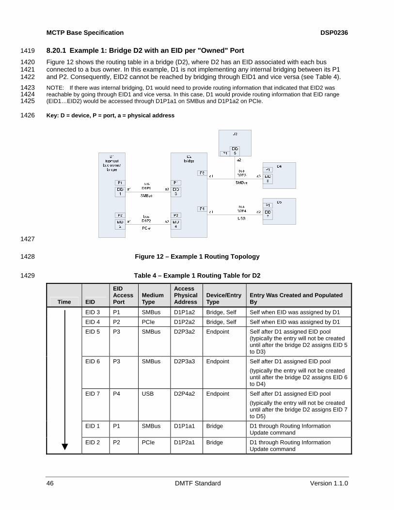
MCTP Base Specification DSP0236
46 DMTF Standard Version 1.1.0
8.20.1 Example 1: Bridge D2 with an EID per "Owned" Port 1419
Figure 12 shows the routing table in a bridge (D2), where D2 has an EID associated with each bus connected to a bus owner. In this example, D1 is not implementing any internal bridging between its P1 and P2. Consequently, EID2 cannot be reached by bridging through EID1 and vice versa (see
1420 1421 1422 1423 1424 1425
1426
Table 4). NOTE: If there was internal bridging, D1 would need to provide routing information that indicated that EID2 was reachable by going through EID1 and vice versa. In this case, D1 would provide routing information that EID range (EID1…EID2) would be accessed through D1P1a1 on SMBus and D1P1a2 on PCIe.
Key: D = device, P = port, a = physical address
1427
1428
1429
Figure 12 – Example 1 Routing Topology
Table 4 – Example 1 Routing Table for D2
Time EID
EID Access Port
Medium Type
Access Physical Address
Device/Entry Type
Entry Was Created and Populated By
EID 3 P1 SMBus D1P1a2 Bridge, Self Self when EID was assigned by D1
EID 4 P2 PCIe D1P2a2 Bridge, Self Self when EID was assigned by D1
EID 5 P3 SMBus D2P3a2 Endpoint Self after D1 assigned EID pool (typically the entry will not be created until after the bridge D2 assigns EID 5 to D3)
EID 6 P3 SMBus D2P3a3 Endpoint Self after D1 assigned EID pool (typically the entry will not be created until after the bridge D2 assigns EID 6 to D4)
EID 7 P4 USB D2P4a2 Endpoint Self after D1 assigned EID pool (typically the entry will not be created until after the bridge D2 assigns EID 7 to D5)
EID 1 P1 SMBus D1P1a1 Bridge D1 through Routing Information Update command
EID 2 P2 PCIe D1P2a1 Bridge D1 through Routing Information Update command

DSP0236 MCTP Base Specification
Version 1.1.0 DMTF Standard 47
8.20.2 Example 2: Topmost Bus Owner D1 1430
Figure 13 assumes the following: 1431
1432
1433
1434
1435 1436
1437
• D1 assigns its internal EIDs first.
• The buses are handled in the order D1P1, D1P2, D1P3.
• D1 allocates the EID pool to bridges right after it has assigned the EID to the device.
Similar to Example 1, this example assumes that there is no internal bridging within D1 between P1, P2, and P3. This scenario is reflected in Table 5.
Key: D = device, P = port, a = physical address
1438
1439
1440
Figure 13 – Example 2 Routing Topology
Table 5 – Example 2 Routing Table for D1
EID
EID Access Port
Medium Type
Access Physical Address
Device/Entry Type Entry Was Created and Populated By
EID 1 P1 SMBus D1P1a1 Bridge, self Self
EID 2 P2 SMBus D1P2a1 Bridge, self Self
EID 3 P3 PCIe D1P3a1 Bridge, self Self
EID 4 P1 SMBus D1P1a2 Endpoint Self upon assigning EID to device D2
EID 5 P2 SMBus D1P2a2 Bridge Self upon assigning EID 5 to bridge D3
EID 6:7 P2 SMBus D1P2a2 Bridge pool Self upon assigning EID pool to bridge D3
EID 8 P3 PCIe D1P3a2 Bridge Self upon assigning EID 8 to bridge D3
EID 6:7 P3 PCIe D1P3a2 Bridge pool Self upon issuing an Allocate Endpoint IDs command and finding that bridge D3 already has an assigned pool, D1 creates this entry by extracting the EIDs for this entry from the response to the Allocate Endpoint IDs command

MCTP Base Specification DSP0236
48 DMTF Standard Version 1.1.0
8.20.3 Example 3: Bridge D2 with Single EID 1441
Figure 14 assumes that bridge D2 has a single EID and gets its EID assignment and EID allocation through bus D1P1 first, and that bus D1P2 later gets initialized. This scenario is reflected in
1442 1443
1444
Table 6.
Key: D = device, P = port, a = physical address
1445
1446
1447
Figure 14 – Example 3 Routing Topology
Table 6 – Example 3 Routing Table for D2
Target EID
Target Endpoint Access Port
Target EID Access Physical Address
Device/Entry Type Entry Was Created and Populated By
EID 3 P1 D1P1a2 Bridge, self
EID 3 P2 D1P2a2 Bridge, self
EID 3 P3 D2P3a1 Bridge, self
EID 3 P4 D2P4a1 Bridge, self
All four entries created by self (bridge) upon receiving initial EID assignment from D1 through P1
EID 4 P3 D2P3a2 Endpoint Self after D1 allocated EID pool
(typically the entry will not be created until after the bridge D2 assigns EID 4 to D3)
EID 5 P3 D2P3a3 Endpoint Self after D1 allocated EID pool
(typically the entry will not be created until after the bridge D2 assigns EID 5 to D4)
EID 6 P3 D2P4a2 Endpoint Self after D1 allocated EID pool
(typically the entry will not be created until after the bridge D2 assigns EID 6 to D5)
EID 1:2 P1 D1P1a1 Bridge D1 through Routing Information Update command
EID 1:2 P2 D1P2a1 Bridge D1 through Routing Information Update command

DSP0236 MCTP Base Specification
Version 1.1.0 DMTF Standard 49
8.20.4 Additional Information Tracked by Bridges 1448
In addition to the information required to route messages between different ports, a bridge has to track information to handle MCTP control commands related to the configuration and operation of bridging (shown in
1449 1450 1451
1452
Table 7).
Table 7 – Additional Information Tracked by Bridges
What Why
Which buses are connected to a bus owner This information tells the bridge from which buses it should request EID assignment. This will typically be accomplished as a non-volatile configuration or hardware-strapping option for the bridge.
Which bus the bridge received its EID assignment through the Set Endpoint ID command
If the bridge uses a single EID that is shared across multiple "owned" buses, this information is used to track which bus the request came in on, so that the bridge can reject EID assignment requests from other buses.
Which bus it received the Routing Information Update command from for creating a particular routing table entry
This information is required so that if a future Routing Information Update command is received, the bridge will update only the entries corresponding to that bus.
Which bus it received its EID pool allocation from through the Allocate Endpoint IDs command
This information is used to track which bus the request came in on so that the bridge can reject EID pool allocations from other buses.
The physical medium and physical addressing format used for each port
This information is used to provide the correctly formatted response to commands such as Resolve Endpoint ID and for bridging MCTP packets between the different buses that the bridge supports. Because this is related to the physical ports and hardware of the bridge, this information will typically be "hard coded" into the bridge.
8.21 Endpoint ID Resolution 1453
When a device uses the Resolve Endpoint ID command to request the resolution of a given endpoint to a physical address, the bridge must respond based on which bus the request came in on.
1454 1455
1456 1457 1458 1459
1460 1461 1462
1463 1464
For example, consider Figure 15. If device A wishes to get the physical address needed to send a message to device C, it sends a Resolve Endpoint ID command to bus owner bridge X through address Ax1. Because device A must go through bridge X to get to device C, bridge X responds with its physical address Ax1.
When device B wishes to know the address to use to communicate with device C, it sends a Resolve Endpoint ID request to bridge X through address Ax2. In this case, bridge X can respond by giving device B the direct physical address of device C on bus 2, Ac2.
Thus, the Resolve Endpoint ID command can return a different response based on the bus from which the Resolve Endpoint ID command was received.

MCTP Base Specification DSP0236
50 DMTF Standard Version 1.1.0
bus 1
bus 2
Ax1
Ab2 Ac2
Ax2
Aa1
notation:Ab2 = physical Address of device b on bus 2.
1465
1466
1468 1469 1470 1471 1472
1473 1474
1475 1476 1477 1478 1479 1480 1481
Figure 15 – Endpoint ID Resolution
8.21.1 Resolving Multiple Paths 1467
Cases can occur where there can be more than one possible path to a given EID. A likely scenario is shown in Figure 16. In Figure 16, assume that the system topology supports cards that connect to either SMBus, PCIe, or both. Bridge X is the bus owner for both buses. NOTE: This is a logical representation of MCTP buses. Physically, the buses may be formed of multiple physical segments, as would be the case if one of the MCTP buses was built using PCIe.
As shown, card C contains a bridge that connects to both buses. Thus, the device with EID 100 can be reached either from bus 1 or bus 2.
If device D wishes to send a message to EID 100, bridge X can choose to route that message either through bus 1 or bus 2. MCTP does not have a requirement on how this is accomplished. The general recommendation is that the bridge preferentially selects the faster available medium. In this example, that would be PCIe. NOTE: There are possible topologies where that simple rule may not yield the preferred path to a device. However, in most common implementations in PC systems, this approach should be effective. A vendor making a bridge device may consider providing configuration options to enable alternative policies.
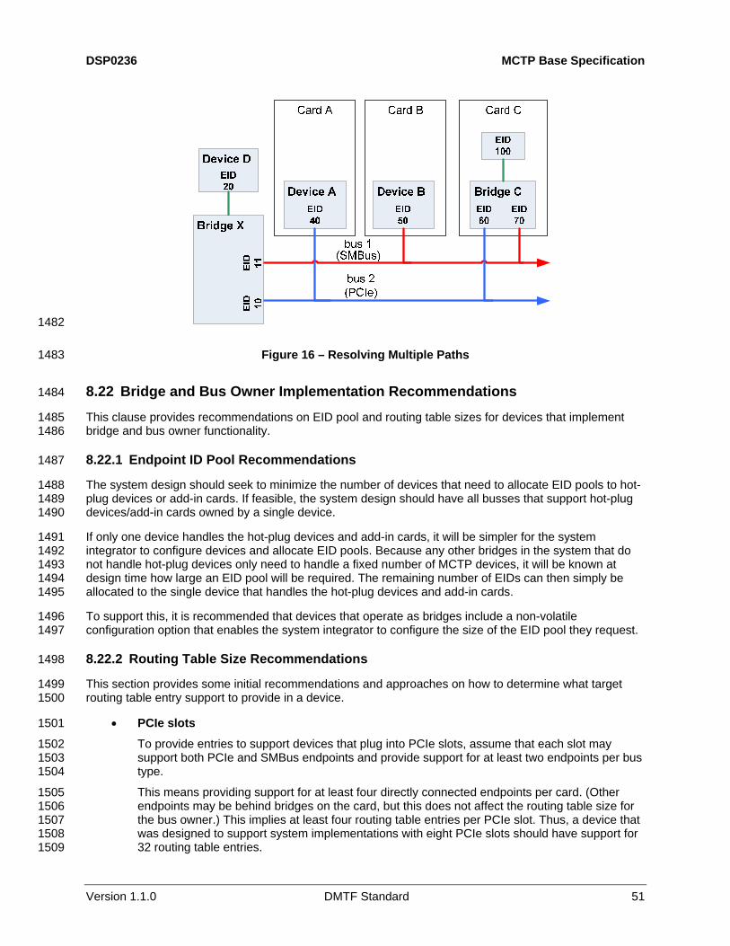
DSP0236 MCTP Base Specification
Version 1.1.0 DMTF Standard 51
1482
1483
1485 1486
1488 1489 1490
1491 1492 1493 1494 1495
1496 1497
1499 1500
1501
1502 1503 1504
1505 1506 1507 1508 1509
Figure 16 – Resolving Multiple Paths
8.22 Bridge and Bus Owner Implementation Recommendations 1484
This clause provides recommendations on EID pool and routing table sizes for devices that implement bridge and bus owner functionality.
8.22.1 Endpoint ID Pool Recommendations 1487
The system design should seek to minimize the number of devices that need to allocate EID pools to hot-plug devices or add-in cards. If feasible, the system design should have all busses that support hot-plug devices/add-in cards owned by a single device.
If only one device handles the hot-plug devices and add-in cards, it will be simpler for the system integrator to configure devices and allocate EID pools. Because any other bridges in the system that do not handle hot-plug devices only need to handle a fixed number of MCTP devices, it will be known at design time how large an EID pool will be required. The remaining number of EIDs can then simply be allocated to the single device that handles the hot-plug devices and add-in cards.
To support this, it is recommended that devices that operate as bridges include a non-volatile configuration option that enables the system integrator to configure the size of the EID pool they request.
8.22.2 Routing Table Size Recommendations 1498
This section provides some initial recommendations and approaches on how to determine what target routing table entry support to provide in a device.
• PCIe slots
To provide entries to support devices that plug into PCIe slots, assume that each slot may support both PCIe and SMBus endpoints and provide support for at least two endpoints per bus type.
This means providing support for at least four directly connected endpoints per card. (Other endpoints may be behind bridges on the card, but this does not affect the routing table size for the bus owner.) This implies at least four routing table entries per PCIe slot. Thus, a device that was designed to support system implementations with eight PCIe slots should have support for 32 routing table entries.

MCTP Base Specification DSP0236
52 DMTF Standard Version 1.1.0
• Planar PCIe devices 1510
1511 1512 1513
1514 1515
1516
1517 1518 1519 1520 1521 1522 1523 1524
In most PC systems, PCIe would be typically implemented as a single MCTP bus owned by a single device as the bus owner. Thus, the number of static devices should be proportional to the number of PCIe devices that are built into the motherboard.
Typically, this is fewer than eight devices. Thus it is recommended to support at least eight entries for static PCIe devices.
• Static SMBus MCTP devices
The routing table should also be sized to support an additional number of "static" devices on owned buses. At this time, it is considered unlikely that more than a few MCTP devices would be used on a given SMBus. Most devices would be non-intelligent sensor and I/O devices instead. Conservatively, it is recommended that at least four entries be provided for each SMBus that the device owns. Example 1: "client" capable device
Four PCIe slots 16 routing table entries Two owned SMBus +8 entries Static PCIe device support +8 entries 1525
1526
1527 1528 1529
~32 entries or more
Example 2: volume server capable Eight PCIe slots 32 routing table entries Four owned SMBus +16 entries Static PCIe device support +8 entries 1530
1531
1533 1534 1535
1536 1537 1538
1539 1540
1542 1543 1544 1545 1546
~56 entries or more
8.23 Path and Transmission Unit Discovery 1532
The transmission unit is defined as the size of the MCTP packet payload that is supported for use in MCTP message assembly for a given message. The supported transmission unit sizes are allowed to vary on a per-message type basis.
Intermediate bridges and physical media can limit the transmission unit sizes between endpoints. Therefore, the MCTP control protocol specifies a mechanism for discovering the transmission unit support for the path between endpoints when one or more bridges exist in the path between the endpoints.
The mechanism for path transmission unit discovery also enables the discovery of the bridges and number of "hops" that are used to route an MCTP packet from one endpoint to another.
8.23.1 Path Transmission Unit Negotiation 1541
The MCTP control protocol only specifies how to discover what the path transmission unit size is for the path between endpoints. The MCTP control protocol does not specify a generic mechanism for discovering what transmission unit sizes a particular endpoint supports for a given message type. Discovery and negotiation of transmission unit sizes for endpoints, if supported, is specified by the definition of the particular message type.

DSP0236 MCTP Base Specification
Version 1.1.0 DMTF Standard 53
8.23.2 Path Transmission Unit Discovery Process Overview 1547
This section describes the process used for path transmission unit discovery. The discovery process described here is designed to enable one endpoint to discover the path and transmission unit support for accessing a particular "target" endpoint. It does not define a general mechanism for enabling an endpoint to discover the path between any two arbitrary endpoints. For example, referring to
1548 1549 1550 1551 1552 1553 1554
Figure 17, the process defines a way for the endpoint at EID 2 to discover the path/transmission unit support on the route to endpoint at EID 6, but this process does not define a process for EID 2 to discover the path/transmission unit support between EID 4 and EID 6.
1555
1556
1557 1558 1559 1560 1561
1562 1563
1564 1565
1566 1567 1568 1569
1570 1571 1572
1573 1574 1575
1576 1577 1578 1579
Figure 17 – Example Path Routing Topology
The following example provides an overview of the path/transmission unit discovery process. The example presumes that the MCTP network has already been initialized. Referring to Figure 17, the endpoint with EID 2 wishes to discover the path used to access the endpoint with EID 6. This discovery is accomplished using just two commands, Resolve Endpoint ID and Query Hop, as follows:
1) EID 2 first issues a Resolve Endpoint ID command to the bus owner, EID 1, with EID 6 as the EID to resolve.
2) EID 1 returns the physical address and EID of the bridge, EID 3 in the Resolve Endpoint ID command response.
3) EID 2 queries the bridge, EID 3, using a Query Hop command with EID 6 (the "target" EID) as the request parameter. Note that EID 2 does not need to do another Resolve Endpoint ID command because it already received the physical address of EID 3 from the original Resolve Endpoint ID command.
4) Bridge EID 3 responds to the Query Hop command by returning EID 5, which is the EID of the next bridge required to access EID 6. The bridge EID 3 also returns the transmission unit support that it offers for routing to the target EID.
5) EID 2 then sends a Query Hop command to the bridge at EID 5. Note that EID 2 does not need to do another Resolve Endpoint ID command because it already received the physical address of EID 5 from the original Resolve Endpoint ID command.
6) Bridge EID 5 responds to the Query Hop command by returning EID 6, which, because it is the EID of the target endpoint, tells EID2 that bridge EID 5 was the last "hop" in the path to EID 6. The bridge EID 5 also returns the transmission unit support that it offers for routing to the target EID.

MCTP Base Specification DSP0236
54 DMTF Standard Version 1.1.0
7) At this point, the bridges in the path to EID 6 have subsequently been discovered and their respective transmission unit support returned. The effective transmission unit support for the path to EID 6 will be the lesser of the transmission unit support values returned by the two bridges.
1580 1581 1582 1583
1585 1586 1587 1588 1589
1590 1591 1592 1593 1594 1595
8.23.3 Path Transmission Unit Discovery Process Flowchart 1584
Figure 18 shows a generic algorithm for discovering the bridges in the path from one endpoint to a given target endpoint and the path transmission unit support. The flowchart has been intentionally simplified. Note that while the Query Hop command actually supports returning separate transmission unit sizes for the transmit and receive paths, the flowchart is simplified for illustration purposes and just refers to a single transmission unit for both transmit and receive.
Additionally, Figure 18 does not show any explicit steps for error handling nor the process of handling command retries. In general, errors are most likely due to either an invalid EID being sent to the bridge (perhaps due to a programming error at the requester) or the EID not being present in the bridge’s routing table. The latter condition could occur under normal operation if the requester did not realize that a routing table update had occurred because of a hot-plug update, for example. This error condition would be indicated by the bridge responding with an ERROR_INVALID_DATA completion code.
1596
1597 Figure 18 – Path Transmission Unit Discovery Flowchart

DSP0236 MCTP Base Specification
Version 1.1.0 DMTF Standard 55
8.24 Path Transmission Unit Requirements for Bridges 1598
An MCTP bridge routes packets between different buses, but it does not typically interpret the packet payload contents nor does it do assembly of those packets. Exceptions to this are when the bridge is handling packets addressed to its own EID, receives a Broadcast EID, and if the bridge supports different transmission units based on message type. See
1599 1600 1601 1602
1604 1605 1606
1608
1609
Table 31 for more information.
9 MCTP Control Protocol 1603
MCTP control messages are used for the setup and initialization of MCTP communications within an MCTP network. This section defines the protocol and formatting used for MCTP control messages over MCTP.
9.1 Terminology 1607
The terms shown in Table 8 are used when describing the MCTP control protocol.
Table 8 – MCTP Control Protocol Terminology
Term Description
Requester The term "requester" is used to refer to the endpoint that originates an MCTP control Request message.
Responder The term "responder" is used to refer to the endpoint that originates an MCTP control response message (that is, an endpoint that returns the response to an MCTP control Request message).
Originator or Source The term "originator" or "source" is used to refer to the endpoint that originates any MCTP control message: Request, Response, or Datagram.
Target or Destination The term "target" or "destination" is used to refer to the endpoint that is the intended recipient of any MCTP control message: Request, Response, or Datagram.
Asynchronous Notification
The term "asynchronous notification" is used to refer to the condition when an MCTP endpoint issues an un-requested Datagram to another MCTP endpoint.
Broadcast The term "broadcast" is used when an MCTP control Datagram is sent out onto the bus using the broadcast EID.
9.1.1 Control Message Classes 1610
The different types of messages shown in Table 9 are used under the MCTP control message type. 1611
1612 Table 9 – MCTP Control Message Types
Type Description
Request This class of control message requests that an endpoint perform a specific MCTP control operation. All MCTP control Request messages are acknowledged with a corresponding Response message. (Within this specification, the term "command" and "request" are used interchangeably as shorthand to refer to MCTP control Request messages.)
Response This class of MCTP control message is sent in response to an MCTP control Request message. The message includes a "Completion Code" field that indicates whether the response completed normally. The response can also return additional data dependent on the particular MCTP control Request that was issued.

MCTP Base Specification DSP0236
56 DMTF Standard Version 1.1.0
Type Description
Datagram Datagrams are "unacknowledged" messages (that is, Datagrams do not have corresponding Response messages). This class of MCTP control message is used to transfer messages when an MCTP control Response message is neither required nor desirable.
Broadcast Request A broadcast message is a special type of Request that is targeted to all endpoints on a given bus. All endpoints that receive the message are expected to interpret the Request.
Broadcast Datagram A Datagram that is broadcast to all endpoints on the bus. Broadcast Datagrams are "unacknowledged" messages (that is, broadcast Datagrams do not have corresponding Response messages).
9.2 MCTP Control Message Format 1613
MCTP control messages use the MCTP control message type (see Table 3). Any message sent with this message type will correspond to the definitions set forth in this section. The basic format of an MCTP control message is shown in
1614 1615 1616 1617
1619 1620
Figure 19. Note that the byte offsets shown in Figure 19 are relative to the start of the MCTP message body rather than the start of the physical packet.
9.2.1 Use of Message Integrity Check 1618
MCTP control messages do not use a Message Integrity Check field. Therefore, the IC bit in MCTP control messages shall always be 0b.
1621
1622
1624
1625
Figure 19 – MCTP Control Message Format
9.3 MCTP Control Message Fields 1623
Table 10 lists the common fields for MCTP control messages.
Table 10 – MCTP Control Message Fields
Field Name Description
IC* Message Integrity Check bit = 0b. MCTP control messages do not include an overall Message Integrity check field.
Message Type* MCTP control = 0x00 (000_0000b). This field identifies the MCTP message as being an MCTP control message.
Rq bit Request bit. This bit is used to help differentiate between MCTP control Request messages and other message classes. Refer to 9.5.

DSP0236 MCTP Base Specification
Version 1.1.0 DMTF Standard 57
Field Name Description
D-bit Datagram bit. This bit is used to indicate whether the Instance ID field is being used for tracking and matching requests and responses, or is just being used to identify a retransmitted message. Refer to 9.5.
Instance ID The Instance ID field is used to identify new instances of an MCTP control Request or Datagram to differentiate new requests or datagrams that are sent to a given message terminus from retried messages that are sent to the same message terminus. The Instance ID field is also used to match up a particular instance of an MCTP Response message with the corresponding instance of an MCTP Request message.
Command Code For Request messages, this field is a command code indicating the type of MCTP operation the packet is requesting. Command code values are defined in Table 12. The format and definition of request and response parameters for the commands is given in Clause 10. The Command Code that is sent in a Request must be returned in the corresponding Response.
Completion Code This field is only present in Response messages. This field contains a value that indicates whether the response completed normally. If the command did not complete normally, the value can provide additional information regarding the error condition. The values for completion codes are specified in Table 13.
Message Data Zero or more bytes of parameter data that is specific to the particular Command Code and whether the message is a Request or Datagram, or a Response.
* These fields are MCTP base protocol fields.
9.4 MCTP Control Message Transmission Unit Size 1626
All MCTP control messages are required to have a packet payload that is no larger than the baseline transmission unit size of 64 bytes.
1627 1628
1629 1630
1632 1633 1634
1635 1636 1637
MCTP control messages are carried in a single MCTP packet. Multiple messages are used if an operation requires more data to be transferred than can be carried in a single message.
9.5 Tag Owner (TO), Request (Rq), and Datagram (D) Bit Usage 1631
For MCTP control messages, the Rq bit is set to 1b if the message is a "command" or Request message and 0b if the message is a Response message. For Datagram and Broadcast messages, the Rq bit is always 1b.
For the present specification, Requests and Datagrams are required to be issued from tag owners ( TO bit = 1b). Provision has been left for the definition of possible future Datagrams that are not issued from tag owners (see Table 11).

MCTP Base Specification DSP0236
58 DMTF Standard Version 1.1.0
Table 11 – Tag Owner (TO), Request (Rq) and Datagram (D) Bit Usage 1638
MCTP Control Message Class Destination EID Value
Tag Owner (TO) bit
Request (Rq) bit
Datagram(D) bit
Command/Request
Responses are expected and tracked by Instance ID at the requester.
Target EID 1b 1b 0b
Response Target EID 0b 0b 0b
Broadcast Request
Responses are expected and tracked by Instance ID at the requester.
Broadcast EID 1b 1b 0b
Datagram
Unacknowledged Request – Responses are neither expected nor tracked by Instance ID at the requester. Duplicate packets are handled the same as retried Command/Request packets.
Target EID 1b 1b 1b
Broadcast Datagram (unacknowledged control command that is broadcast.)
Broadcast EID 1b 1b 1b
Reserved for future definition all other
9.6 Concurrent Command Processing 1639
This section describes the specifications and requirements for handling concurrent overlapping MCTP control requests by endpoints.
1640 1641
1643 1644 1645
1646 1647
1649 1650 1651
1652 1653
1654 1655 1656 1657 1658
9.6.1 Requirements for Responders 1642
An endpoint is not required to process more than one request at a time (that is, it can be "single threaded" and does not have to accept and act on new requests until it has finished responding to any previous request).
A responder that is not ready to accept a new request can either silently discard the request, or it can respond with an ERROR_NOT_READY message completion code.
9.6.2 Requirements for Requesters 1648
An endpoint that issues MCTP control Requests to another endpoint must wait until it gets the response to the particular request, or times out waiting for the response, before issuing a new request, Datagram, or Broadcast Datagram.
An endpoint that issues MCTP control Requests is allowed to have multiple requests outstanding simultaneously to different responder endpoints.
An endpoint that issues MCTP control Requests should be prepared to handle responses that may not match the request (that is, it should not automatically assume that a response that it receives is for a particular request). It should check to see that the command code and source EID values in the response match up with a corresponding outstanding command before acting on any parameters returned in the response.

DSP0236 MCTP Base Specification
Version 1.1.0 DMTF Standard 59
9.6.3 Additional Requirements for Bridges 1659
The packets that are routed through a bridge’s routing functionality are not interpreted by the bridge and therefore are not considered to constitute concurrent requests.
1660 1661
1662 1663 1664
1665
1667 1668 1669
1671 1672 1673 1674
1675
A bridge must support at least one outstanding MCTP control request for each bus connection (port) through which MCTP control messages can be used to access the bridge’s configuration and control functionality.
Bridges must retain temporal ordering of packets forwarded from one message terminus to another.
10 MCTP Control Messages 1666
This section contains detailed descriptions for each MCTP control message. The byte offsets for the Request and Response parameter information given in the tables for the commands indicates the byte offset for the message data starting with the byte following the Command field.
10.1 MCTP Control Message Command Codes 1670
Table 12 lists the MCTP control messages and their corresponding command code values. The commands and their associated parameters are specified later in this section. For bridges, the requirements apply equally to all endpoints within the bridge device that are used to configure and control the bridges routing functionality.
Table 12 – MCTP Control Command Numbers
OMC Command Code Command Name General Description E B Section 0x00 Reserved Reserved – – – 0x01 Set Endpoint ID Assigns an EID to the endpoint at the given
physical address Ma Ng
Ca1
Mg 10.3
0x02 Get Endpoint ID Returns the EID presently assigned to an endpoint. Also returns information about what type the endpoint is and its level of use of static EIDs.
Ma Og
Ma Og
10.4
0x03 Get Endpoint UUID Retrieves a per-device unique UUID associated with the endpoint
Ca2
Og Ca2
Og 10.5
0x04 Get MCTP Version Support
Lists which versions of the MCTP control protocol are supported on an endpoint
Ma Og
Ma Og5
10.6
0x05 Get Message Type Support
Lists the message types that an endpoint supports
Ma Og
Ma Og
10.7
0x06 Get Vendor Defined Message Support
Used to discover an MCTP endpoint’s vendor-specific MCTP extensions and capabilities
Oa Og
Oa Og
10.8
0x07 Resolve Endpoint ID Used to get the physical address associated with a given EID
Na Og
Ma Og
10.9
0x08 Allocate Endpoint IDs
Used by the bus owner to allocate a pool of EIDs to an MCTP bridge
Na Ng
Ma6
Mg6 10.10
0x09 Routing Information Update
Used by the bus owner to extend or update the routing information that is maintained by an MCTP bridge
Na Ng
Ma4
Mg4 10.11
0x0A Get Routing Table Entries
Used to request an MCTP bridge to return data corresponding to its present routing table entries
Na Og
Ma Og
10.12
0x0B Prepare for Endpoint Discovery
Used to direct endpoints to clear their "discovered" flags to enable them to respond to the Endpoint Discovery command
Ca3
Ng Ca3
Cg3 10.13

MCTP Base Specification DSP0236
60 DMTF Standard Version 1.1.0
OMC Command Code Command Name General Description E B Section 0x0C Endpoint Discovery Used to discover MCTP-capable devices on a
bus, provided that another discovery mechanism is not defined for the particular physical medium
Ca3
Cg3 Ca3 Cg3
10.14
0x0D Discovery Notify Used to notify the bus owner that an MCTP device has become available on the bus
Na Cg3
Ca3
Cg3 10.15
0x0E Get Network ID Used to get the MCTP network ID Ca7 Ca7 10.15 0x0F Query Hop Used to discover what bridges, if any, are in the
path to a given target endpoint and what transmission unit sizes the bridges will pass for a given message type when routing to the target endpoint
Na Og
Ma Og
10.16
0xF0 - 0xFF
Transport Specific This range of control command numbers is reserved for definition by individual MCTP Transport binding specifications. Transport-specific commands are intended to be used as needed for setup and configuration of MCTP on a given media. A particular transport-specific command number may have different definitions depending on the binding specification. Transport-specific commands shall only be addressed to endpoints on the same medium. A bridge is allowed to block transport-specific commands from being bridged to different media. The general format of transport-specific messages is specified in 10.18.
- - 10.17
Key for OMC (optional / mandatory / conditional) column: E = non-bridge, non-bus owner endpoint (simple endpoint) B = bridge / bus-owner endpoint Ma = mandatory (required) to accept. The request must be accepted by the endpoint and a response generated per the
following command descriptions. Mg = mandatory to generate. The endpoint must generate this request as part of its responsibilities for MCTP operation. Oa = optional to accept Og = optional to generate Ca = conditional to accept (see notes) Cg = conditional to generate (see notes) Na = not applicable to accept. This command is not applicable to the device type and must not be accepted Ng = not applicable to generate. This command is used for MCTP configuration and initialization and should not be
generated. 1. The topmost bus owner is not required to support the Set Endpoint ID command. 2. Hot-plug and add-in devices are required to support the Get Endpoint UUID command. 3. Mandatory on a per-bus basis to support endpoint discovery if required by the physical transport binding used for the
particular bus type. Refer to the appropriate MCTP physical transport binding specification. 4. The topmost bus owner is not required to accept this command. The command is required to be generated when
downstream bridges require dynamic routing information from bus owners that they are connected to. Some implementations may be configured where all routing information has been statically configured into the bridge and no dynamically provided information is required, In this case, it is not required to support the command while the endpoints are configured in that manner.
5. Bridges should use this command to verify that they are initializing devices that are compatible with their MCTP control protocol version.
6. The endpoint is required to accept this command if it indicated support for a dynamic EID pool. The command must be generated by the endpoint if the configuration requires the endpoint to support allocating EID pools to downstream bridges.
7. See Section 8.19 MCTP Network IDs for information for implementation requirements of this command.
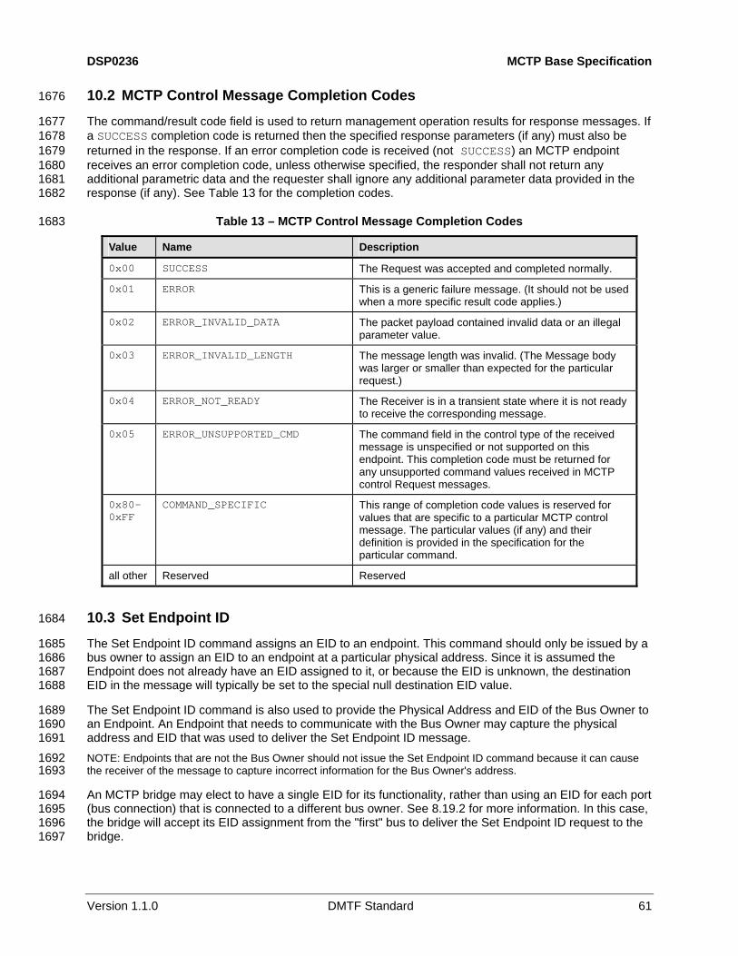
DSP0236 MCTP Base Specification
Version 1.1.0 DMTF Standard 61
10.2 MCTP Control Message Completion Codes 1676
The command/result code field is used to return management operation results for response messages. If a SUCCESS completion code is returned then the specified response parameters (if any) must also be returned in the response. If an error completion code is received (not SUCCESS) an MCTP endpoint receives an error completion code, unless otherwise specified, the responder shall not return any additional parametric data and the requester shall ignore any additional parameter data provided in the response (if any). See
1677 1678 1679 1680 1681 1682
1683
Table 13 for the completion codes.
Table 13 – MCTP Control Message Completion Codes
Value Name Description
0x00 SUCCESS The Request was accepted and completed normally.
0x01 ERROR This is a generic failure message. (It should not be used when a more specific result code applies.)
0x02 ERROR_INVALID_DATA The packet payload contained invalid data or an illegal parameter value.
0x03 ERROR_INVALID_LENGTH The message length was invalid. (The Message body was larger or smaller than expected for the particular request.)
0x04 ERROR_NOT_READY The Receiver is in a transient state where it is not ready to receive the corresponding message.
0x05 ERROR_UNSUPPORTED_CMD The command field in the control type of the received message is unspecified or not supported on this endpoint. This completion code must be returned for any unsupported command values received in MCTP control Request messages.
0x80–0xFF
COMMAND_SPECIFIC This range of completion code values is reserved for values that are specific to a particular MCTP control message. The particular values (if any) and their definition is provided in the specification for the particular command.
all other Reserved Reserved
10.3 Set Endpoint ID 1684
The Set Endpoint ID command assigns an EID to an endpoint. This command should only be issued by a bus owner to assign an EID to an endpoint at a particular physical address. Since it is assumed the Endpoint does not already have an EID assigned to it, or because the EID is unknown, the destination EID in the message will typically be set to the special null destination EID value.
1685 1686 1687 1688
1689 1690 1691 1692 1693
1694 1695 1696 1697
The Set Endpoint ID command is also used to provide the Physical Address and EID of the Bus Owner to an Endpoint. An Endpoint that needs to communicate with the Bus Owner may capture the physical address and EID that was used to deliver the Set Endpoint ID message. NOTE: Endpoints that are not the Bus Owner should not issue the Set Endpoint ID command because it can cause the receiver of the message to capture incorrect information for the Bus Owner's address.
An MCTP bridge may elect to have a single EID for its functionality, rather than using an EID for each port (bus connection) that is connected to a different bus owner. See 8.19.2 for more information. In this case, the bridge will accept its EID assignment from the "first" bus to deliver the Set Endpoint ID request to the bridge.

MCTP Base Specification DSP0236
62 DMTF Standard Version 1.1.0
It is recognized that different internal processing delays within a bridge can cause the temporal ordering of requests to be switched if overlapping requests are received over more than one bus. Therefore, which request is accepted by an implementation is not necessarily tied to the request that is first received at the bridge, but instead will be based on which request is the first to be processed by the bridge.
1698 1699 1700 1701
1702 1703 1704
1705 1706 1707 1708 1709 1710 1711
1712
If an EID has already been assigned and the Set Endpoint ID command is issued from a different bus without forcing an EID assignment, the command shall return a SUCCESSFUL completion code, but the response parameters shall return an EID assignment status of "EID rejected".
The Set Endpoint ID command functions in the same manner regardless of whether the endpoint uses a static EID. The only difference is that if an endpoint has a static EID, it uses that EID as its initial "default" EID value. The endpoint does not treat this initial EID as if it were assigned to it by a different bus owner. That is, the endpoint shall accept the EID assignment from the first bus that the command is received from, and shall track that bus as the originating bus for the EID for subsequent instances of Set Endpoint ID command. See 8.17.2 for more information. The request and response parameters are specified in Table 14.
Table 14 – Set Endpoint ID Message
Byte Description
Request data 1 Operation
[7:3] – reserved
[1:0] – Operation:
00b Set EID. Submit an EID for assignment. The given EID will be accepted conditional upon which bus the device received the EID from (see preceding text). A device where the endpoint is only reached through one bus shall always accept this operation (provided the EID value is legal).
01b Force EID. Force EID assignment. The given EID will be accepted regardless of whether the EID was already assigned through another bus. Note that if the endpoint is forcing, the EID assignment changes which bus is being tracked as the originator of the Set Endpoint ID command. A device where the endpoint is only reached through one bus shall always accept this operation (provided the EID value is legal), in which case the Set EID and Force EID operations are equivalent.
10b Reset EID (optional). This option only applies to endpoints that support static EIDs. If static EIDs are supported, the endpoint shall restore the EID to the statically configured EID value. The EID value in byte 2 shall be ignored. An ERROR_INVALID_DATA completion code shall be returned if this operation is not supported.
11b Set Discovered Flag. Set Discovered flag to the "discovered" state only. Do not change present EID setting. The EID value in byte 2 shall be ignored. Note that Discovered flag is only used for some physical transport bindings. An ERROR_INVALID_DATA completion code shall be returned if this operation is selected and the particular transport binding does not support a Discovered flag.
2 Endpoint ID.
0xFF, 0x00 = illegal. Endpoints are not allowed to be assigned the broadcast or null EIDs. It is recommended that the endpoint return an ERROR_INVALID_DATA

DSP0236 MCTP Base Specification
Version 1.1.0 DMTF Standard 63
Byte Description completion code if it receives either of these values.
1 Completion code
2 [7:6] – reserved
[5:4] – EID assignment status:
00b = EID assignment accepted. 01b = EID assignment rejected. EID has already been assigned by
another bus owner and assignment was not forced.
10b = reserved. 11b = reserved.
[3:2] – reserved.
[1:0] – Endpoint ID allocation status (see 10.10 for additional information):
00b = Device does not use an EID pool. 01b = Endpoint requires EID pool allocation. 10b = Endpoint uses an EID pool and has already received an
allocation for that pool.
11b = reserved
3 EID Setting.
If the EID setting was accepted, this value will match the EID passed in the request. Otherwise, this value returns the present EID setting.
Response data
4 EID Pool Size.
This is the size of the dynamic EID pool that the bridge can use to assign EIDs or EID pools to other endpoints or bridges. It does not include the count of any additional static EIDs that the bridge may maintain. See 8.17.2 for more information. Note that a bridge always returns its pool size regardless of whether it has already received an allocation.
0x00 = no dynamic EID pool.
10.4 Get Endpoint ID 1713
The Get Endpoint ID command returns the EID for an endpoint. This command is typically issued only by a bus owner to retrieve the EID that was assigned to a particular physical address. Thus, the destination EID in the message will typically be set to the special Physical Addressing Only EID value. The request and response parameters are specified in
1714 1715 1716 1717
1718
Table 15.
Table 15 – Get Endpoint ID Message
Byte Description
Request data – –
1 Completion Code.
2 Endpoint ID.
0x00 = EID not yet assigned.
Response data
3 Endpoint Type. [7:6] = reserved [5:4] = Endpoint Type:
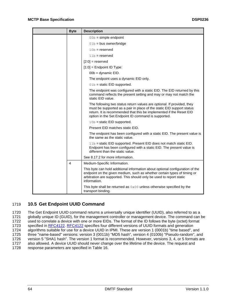
MCTP Base Specification DSP0236
64 DMTF Standard Version 1.1.0
Byte Description
00b = simple endpoint
01b = bus owner/bridge
10b = reserved
11b = reserved
[2:0] = reserved [1:0] = Endpoint ID Type:
00b = dynamic EID. The endpoint uses a dynamic EID only.
01b = static EID supported.
The endpoint was configured with a static EID. The EID returned by this command reflects the present setting and may or may not match the static EID value. The following two status return values are optional. If provided, they must be supported as a pair in place of the static EID support status return. It is recommended that this be implemented if the Reset EID option in the Set Endpoint ID command is supported.
10b = static EID supported.
Present EID matches static EID. The endpoint has been configured with a static EID. The present value is the same as the static value.
11b = static EID supported. Present EID does not match static EID. Endpoint has been configured with a static EID. The present value is different than the static value.
See 8.17.2 for more information.
4 Medium-Specific Information. This byte can hold additional information about optional configuration of the endpoint on the given medium, such as whether certain types of timing or arbitration are supported. This should only be used to report static information.
This byte shall be returned as 0x00 unless otherwise specified by the transport binding.
10.5 Get Endpoint UUID Command 1719
The Get Endpoint UUID command returns a universally unique identifier (UUID), also referred to as a globally unique ID (GUID), for the management controller or management device. The command can be used to correlate a device with one or more EIDs. The format of the ID follows the byte (octet) format specified in
1720 1721 1722
RFC4122. RFC4122 specifies four different versions of UUID formats and generation algorithms suitable for use for a device UUID in IPMI. These are version 1 (0001b) "time based", and three "name-based" versions: version 3 (0011b) "MD5 hash", version 4 (0100b) "Pseudo-random", and version 5 "SHA1 hash". The version 1 format is recommended. However, versions 3, 4, or 5 formats are also allowed. A device UUID should never change over the lifetime of the device. The request and response parameters are specified in
1723 1724 1725 1726 1727 1728 Table 16.
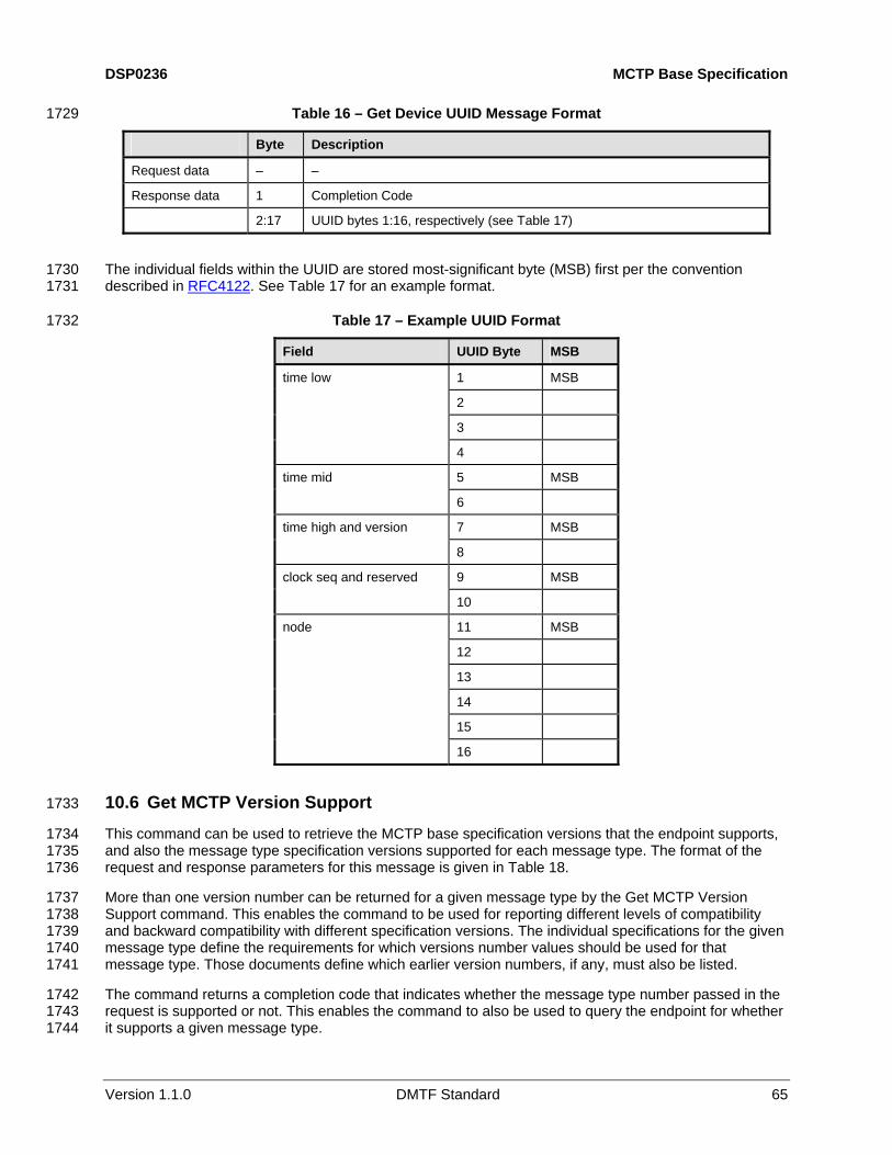
DSP0236 MCTP Base Specification
Version 1.1.0 DMTF Standard 65
Table 16 – Get Device UUID Message Format 1729
Byte Description
Request data – –
Response data 1 Completion Code
2:17 UUID bytes 1:16, respectively (see Table 17)
The individual fields within the UUID are stored most-significant byte (MSB) first per the convention described in
1730 RFC4122. See Table 17 for an example format. 1731
1732 Table 17 – Example UUID Format
Field UUID Byte MSB
1 MSB
2
3
time low
4
5 MSB time mid
6
7 MSB time high and version
8
9 MSB clock seq and reserved
10
11 MSB
12
13
14
15
node
16
10.6 Get MCTP Version Support 1733
This command can be used to retrieve the MCTP base specification versions that the endpoint supports, and also the message type specification versions supported for each message type. The format of the request and response parameters for this message is given in
1734 1735 1736
1737 1738 1739 1740 1741
1742 1743 1744
Table 18.
More than one version number can be returned for a given message type by the Get MCTP Version Support command. This enables the command to be used for reporting different levels of compatibility and backward compatibility with different specification versions. The individual specifications for the given message type define the requirements for which versions number values should be used for that message type. Those documents define which earlier version numbers, if any, must also be listed.
The command returns a completion code that indicates whether the message type number passed in the request is supported or not. This enables the command to also be used to query the endpoint for whether it supports a given message type.

MCTP Base Specification DSP0236
66 DMTF Standard Version 1.1.0
NOTE: Version numbers are listed from oldest to newest. This specification is backward compatible with version 1.0.x.x. Therefore, the response data shall return two Version Number entries: 1.0.x.x for Version Number entry 1 and 1.1.x.x for Version Number entry 2.
1745 1746 1747
1748 Table 18 – Get MCTP Version Support Message
Byte Description
Request data 1 Message Type Number
The Message Type Number to retrieve version information for:
0xFF = return MCTP base specification version information.
0x00 = return MCTP control protocol message version information.
other = return version information for a given message type. See MCTP ID and Table 3 for message type numbers.
1 Completion Code
0x80 = message type number not supported
2 Version Number Entry count
One-based count of 32-bit version numbers being returned in this response. Numerically lower version numbers are returned first.
3:6 Version Number entry 1: The following descriptions are informational. Refer to DSP4004 for the normative definition of version numbering of DMTF specifications.
[31:24] = major version number. This field is used to identify a version of the specification that includes changes that make it incompatible with one or more functions that were defined in versions of the specification that have an older (smaller) major version number.
[23:16] = minor version number. This field is used to identify functional additions to the specification that are backward compatible with older (smaller) minor version numbers that share the same major version number.
[15:8] = update version number. This field is used for editorial updates to the specification that do not define new functionality nor change existing functionality over the given major.minor release. This field is informational and should be ignored when checking versions for interoperability.
[7:0] = "alpha" byte. This value is used for pre-release (work-in-progress) versions of the specification. Pre-release versions of the specification are backward compatible with specification versions that have an older (smaller) minor version numbers that share the same major version number. However, since the alpha value represents a version of the specification that is presently under development, versions that share the same major and minor version numbers, but have different 'alpha' versions may not be fully interoperable.
The encoding of the version number and alpha fields is provided in 10.6.1.
Response data
(7:X) Version Number Entries 2 through N.
Additional 32-bit major/minor version numbers, if any.

DSP0236 MCTP Base Specification
Version 1.1.0 DMTF Standard 67
10.6.1 Version Field Encoding 1749
The version field is comprised of four bytes referred to as the "major", "minor", "update", and "alpha" bytes. These bytes shall be encoded as follows:
1750 1751
1752 1753
The "major", "minor", and "update" bytes are BCD-encoded, and each byte holds two BCD digits. The "alpha" byte holds an optional alphanumeric character extension that is encoded using the ISO/IEC 8859-1 Character Set. The semantics of these fields follows that specified in DSP4004. 1754
1755 1756
1757 1758 1759 1760
1761 1762 1763 1764 1765 1766 1767 1768 1769
1771 1772
1773
1774
1775 1776
1777
1778
1780 1781 1782 1783
1784 1785 1786
The value 0x00 in the alpha field means that the alpha field is not used. Software or utilities that display the version number should not display any characters for this field.
The value 0xF in the most-significant nibble of a BCD-encoded value indicates that the most-significant nibble should be ignored and the overall field treated as a single-digit value. Software or utilities that display the number should only display a single digit and should not put in a leading "0" when displaying the number.
A value of 0xFF in the "update" field indicates that the field to be ignored. Software or utilities that display the version number should not display any characters for the field. 0xFF is not allowed as a value for the "major" or "minor" fields. EXAMPLES:
Version 1.1.0 → 0xF1F1F000 Version 3.1 → 0xF3F1FF00 Version 1.0a → 0xF1F0FF61 Version 3.7.10a → 0xF3F71061 Version 10.11.7 → 0x1011F700
10.6.2 MCTP Base Specification Version Number 1770
The Version Number Entry 1 field shall be used to indicate backward compatibility with Version 1.0 of the base specification as:
1.0 [Major version 1, minor version 0, no update version, no alpha)]
This is reported using the encoding as: 0xF1F0FF00
The version of the MCTP base specification for this specification shall be reported in Version Number Entry 2 as:
1.1.0 [Major version 1, minor version 1, update version 0, no alpha)]
This is reported using the encoding as: 0xF1F1F000
10.7 Get Message Type Support 1779
The Get Message Type Support command enables management controllers to discover the MCTP control protocol capabilities supported by other MCTP endpoints, and get a list of the MCTP message types that are supported by the endpoint. The request and response parameters for this message are listed in Table 19.
The response to this command may be specific according to which bus the request was received over (that is, a device that supports a given message type may not support that message type equally across all buses that connect to the device).

MCTP Base Specification DSP0236
68 DMTF Standard Version 1.1.0
Table 19 – Get Message Type Support Message 1787
Byte Description
Request data – –
1 Completion Code.
2 MCTP Message Type Count. One-based.
Number of message types in addition to the MCTP control message type that is supported by this endpoint
Response data
(3:N) List of Message Type numbers. One byte per number. See Table 3 and MCTP ID.
10.8 Get Vendor Defined Message Support 1788
The Get Vendor Defined Message Support operation enables management controllers to discover whether the endpoint supports vendor-defined messages, and, if so, the vendors or organizations that defined those messages. The format and definition of the request and response parameters for this message is given in
1789 1790 1791 1792
1793
Table 20.
Table 20 – Get Vendor Defined Message Support Message
Byte Description
Request data 1 Vendor ID Set Selector
Indicates the specific capability set requested. Indices start at 0x00 and increase monotonically by 1. If the responding endpoint has one or more capability sets with indices greater than the requested index, it increments the requested index by 1 and returns the resulting value in the response message. The requesting endpoint uses the returned value to request the next capability set.
1 Completion Code
2 Vendor ID Set Selector
0xFF = no more capability sets.
var Vendor ID
A structured field of variable length that identifies the vendor ID format (presently PCI or IANA) and the ID of the vendor that defined the capability set. The structure of this field is specified in Figure 20.
Response data
2 bytes
16-bit numeric value or bit field, as specified by the vendor or organization identified by the vendor ID. This value is typically used to identify a particular command set type or major version under the given vendor ID.
10.8.1 Vendor ID Formats 1794
Figure 20 shows the general structure of Vendor ID fields used in this specification. The first byte of the field contains the Vendor ID Format, a numeric value that indicates the definition space and format of the ID. The remainder of the field holds the Vendor ID Data with content and format as specified in
1795 1796 1797
1798 1799 1800
Table 21.
The MCTP management controller or management device can pick which format is best suited for the device. In general, if the device does not already have an existing vendor ID that matches one of the specified formats, it is recommended that the IANA enterprise number format be used.

DSP0236 MCTP Base Specification
Version 1.1.0 DMTF Standard 69
1801
1802
1803
Figure 20 – Structure of Vendor ID Field for Get Vendor Defined Capabilities Message
Table 21 – Vendor ID Formats
Vendor ID Format Name
Vendor ID Format
Vendor ID Data Length Description
PCI Vendor ID 0x00 2 16-bit Unsigned Integer. The PCI 2.3 specifications state the following about the PCI vendor ID: "This field identifies the manufacturer of the device. Valid vendor identifiers are allocated by the PCI SIG to ensure uniqueness. 0xFFFF is an invalid value for the Vendor ID." However, for MCTP this value may be used for identifying aspects other than the manufacturer of the device, such as its use in the Vendor Defined - PCI message type, where it identifies the vendor or organization that defined a particular set of vendor-defined messages. Thus, in some uses, the ID may or may not correspond to the PCI ID for the manufacturer of the device.
IANA Enterprise Number
0x01 4 32-bit Unsigned Integer. The IANA enterprise number for the organization or vendor expressed as a 32-bit unsigned binary number. For example, the enterprise ID for the DMTF is 412 (decimal) or 0x0000_019C expressed as a 32-bit hexadecimal number. The enterprise number is assigned and maintained by the Internet Assigned Numbers Authority, www.iana.org, as a means of identifying a particular vendor, company, or organization.
10.9 Resolve Endpoint ID 1804
This command is sent to the bus owner to resolve an EID into the physical address that must be used to deliver MCTP messages to the target endpoint. The command takes an EID as an input parameter in the request and returns the EID and the physical address for routing to that EID (if any) in the response. The response data will also indicate if no mapping was available.
1805 1806 1807 1808
1809 1810 1811 1812 1813
An endpoint knows the physical address of the bus owner by keeping track of which physical address was used when the endpoint received its EID assignment through the Set Endpoint ID command. The endpoint can send this command to the bus owner using the null destination EID value. This eliminates the need for the endpoint to also keep track of the EID of the bus owner. The request and response parameters are specified in Table 22.

MCTP Base Specification DSP0236
70 DMTF Standard Version 1.1.0
Table 22 – Resolve Endpoint ID Message 1814
Byte Description
Request data 1 Target Endpoint ID
This is the EID that the bus owner is being asked to resolve.
1 Completion Code
2 Bridge Endpoint ID
This is the EID for the endpoint that is providing the bridging server (if any) that is required to access the target endpoint.
If the EID being returned matches the same value as the target EID, it indicates that there is no bridging function that is required to access the target endpoint (that is, the target EID is local to the bus that the Resolve Endpoint ID request was issued over).
Response data
3:N Physical Address.
The size of this field is dependent on the particular MCTP physical transport binding used for the bus that this data is being provided for. The size and format of this field is defined as part of the corresponding physical transport binding specification.
10.10 Allocate Endpoint IDs 1815
Bus owners are responsible for allocating pools of EIDs to MCTP bridges that are lower in the bus hierarchy. This is done using the Allocate Endpoint IDs command. The EID for the bridge itself is assigned separately and is not part of the pool given with this command.
1816 1817 1818
1819 1820 1821 1822 1823 1824 1825
1826 1827 1828
1829 1830 1831 1832
1833 1834 1835
The bus owner will typically use this command as part of the EID assignment process for a bus. When a device has been assigned an EID using the Set Endpoint ID command, the response to that command indicates whether the endpoint supports an EID pool. If the device indicates that it supports an EID pool, the bus owner can then issue the Allocate Endpoint IDs command to supply the pool of EIDs to the device. NOTE: The Allocate Endpoint IDs command can also cause a bridge to rebuild its routing table. See 10.11.2 for more information.
When an EID or EID pool that was previously allocated becomes unused (for example, due to a hot-swap removal), the bus owner must reclaim the endpoint’s EID or EID pool allocation. See 8.17 for additional details.
Referring to Figure 21, there is a potential race condition with handling EID allocation. In the scenario shown in this figure, it is possible that device X and device Z might both be assigning EIDs to device Y at the same time. This also means that, unless steps are taken, device Z could allocate endpoints to device Y only to have this overwritten by a set of endpoints assigned by device X.
To prevent this, the Allocate Endpoint IDs command is only accepted from the "first" bus that provides the EID pool to the device. If another bus owner attempts to deliver an EID pool through another bus, the request will be rejected unless an intentional over-ride is done.

DSP0236 MCTP Base Specification
Version 1.1.0 DMTF Standard 71
1836
1837
1838
1839
Figure 21 – EID Pools from Multiple Bus Owners
The Allocate Endpoint IDs message fields are described in Table 23.
Table 23 – Allocate Endpoint IDs Message
Byte Description
Request data 1 Operation Flags: [7:1] – reserved. [1:0] – Operation:
00b = allocate EIDs. Submit an EID pool allocation. Do not force allocation. This enables the allocation to be rejected if the bridge has already received its EID pool from another bus. (See additional information in the following sections.) 01b = Force allocation. Force bridge to accept this EID pool regardless of whether it has already received its EID pool from another bus. This shall also cause a bridge to rebuild its routing tables, See 10.11.2 for more information. 10b = Get allocation information Return the response parameters without changing the present allocation. This can be used to query information on the dynamic pool of EIDs presently allocated to the Endpoint, if any. If this operation is selected, the Number of Endpoint IDs and Starting Endpoint ID parameters in the request shall be ignored. 11b = Reserved
1840

MCTP Base Specification DSP0236
72 DMTF Standard Version 1.1.0
Byte Description
2 Number of Endpoint IDs Specifies the number of EIDs in the pool being made available to this Endpoint
3 Starting Endpoint ID Specifies the starting EID for the range of EIDs being allocated in the pool. When multiple EIDs are provided, the IDs are sequential starting with this value as the first EID in the range.
1 Completion Code An error completion code shall be returned if the number of EIDs assigned does not match the pool size. (This error condition does not apply to when the number of endpoint IDs passed in the request is 0xFF or 0x00).
2 [7:2] – reserved [1:0] – 00b = Allocation was accepted
01b = Allocation was rejected. The Allocate Endpoint IDs command is accepted only from the "first" bus that provides the EID pool to the device. If another bus owner attempts to deliver an EID pool through another bus, the request will be rejected unless an intentional over-ride is done. (The rationale for this behavior is explained in the text of this section.) 10b, 11b = reserved
3 Endpoint ID Pool Size This value is the size of the EID pool used by this endpoint. This is the size of the dynamic EID pool that the bridge can use to assign EIDs or EID pools to other endpoints or bridges. It does not include the count of any additional static EIDs that the bridge may maintain. See 8.17.2 for more information.
Response data
4 First Endpoint ID This field specifies the first EID assigned to the pool for this endpoint. The value is 0x00 if there are no EIDs assigned to the pool.
10.11 Routing Information Update 1841
The Routing Information Update message is used by a bus owner to give routing information to a bridge for the bus on which the message is being received.
1842 1843
1844 1845
1846 1847 1848
1850 1851 1852 1853 1854 1855 1856 1857
Because the physical address format is based on the bus over which the request is delivered, the bus owner must use the medium-specific physical address format for the addresses sent using this command.
An MCTP bridge may be sent more than one instance of this command to transfer the update information. An integral number of routing information update entries must be provided in the command (that is, routing information update entries cannot be split across instances of the command).
10.11.1 Adding and Replacing Entries 1849
The recipient of this command must check to see whether the information in the request corresponds to the EID for an existing entry for the bus over which the command was received. If so, it must replace that entry with the new information. If an entry for a given EID or EID range does not already exist, it must create new entries for the given EIDs. In some cases this may require the bridge to split existing entries into multiple entries. NOTE: A bus owner is only allowed to update entries that correspond to its bus. For each routing table entry that was created or updated through the Routing Information Update message, the bridge must keep track of which bus it received the Routing Information Update from. This is necessary so that when a Routing Information Update is

DSP0236 MCTP Base Specification
Version 1.1.0 DMTF Standard 73
received from a particular bus, the bridge only updates entries that correspond to entries that were originally given to it from that bus.
1858 1859
1861 1862 1863 1864
1865
10.11.2 Rebuilding Routing Tables 1860
A bridge that receives and accepts the Allocate Endpoint IDs command with the "Force Allocation" bit set (1b) must clear out and rebuild its routing table information. The bridge shall issue commands to reassign EIDs and re-allocate EID pools to all downstream devices. The request and response parameters are specified in Table 24, and format information is provided in Table 25.
Table 24 – Routing Information Update Message
Byte Description
1 Count of update entries (1-based) Request data
see text
One or more update entries, based on the given count, as illustrated in Table 25
Response data 1 Completion Code
0x80 = Insufficient space to add requested entries to internal routing table
Table 25 – Routing Information Update Entry Format 1866
Byte Description
1 [7:4] - reserved
[3:0] - Entry Type:
00b = entry corresponds to a single endpoint that is not serving as an MCTP bridge
01b = entry reflects an EID range for a bridge where the starting EID is the EID of the bridge itself and additional EIDs in the range are routed by the bridge
10b = entry is for a single endpoint that is serving as an MCTP bridge
11b = entry is an EID range for a bridge, but does not include the EID of the bridge itself
2 [7:0] Size of EID Range. The count of EIDs in the range.
3 First EID in EID Range.
The EID Range is sequential (for example, if the size of the EID Range is 3 and the First EID value given in this parameter is 21, the Entry covers EIDs 21, 22, and 23).
4:N Physical Address. The size and format of this field is defined as part of the corresponding physical transport binding specification for the bus that this data is being provided for.
10.12 Get Routing Table Entries 1867
This command can be used to request an MCTP bridge to return data corresponding to its present routing table entries. This data is used to enable troubleshooting the configuration of routing tables and to enable software to draw a logical picture of the MCTP network. More than one instance of this command will typically need to be issued to transfer the entire routing table content.
1868 1869 1870 1871

MCTP Base Specification DSP0236
74 DMTF Standard Version 1.1.0
An integral number of routing table entries must be provided in the response to this command (that is, routing table entries cannot be split across instances of the command). The request and response parameters are specified in
1872 1873 1874
1875
Table 26, and format information is provided in Table 27.
Table 26 – Get Routing Table Entries Message
Byte Description
Request data 1 Entry Handle (0x00 to access first entries in table)
1 Completion Code
2 Next Entry Handle (Use this value to request the next set of entries, if any.) If the routing table data exceeds what can be carried in a single MCTP control response. 0xFF = No more entries
3 Number of routing table entries being returned in this response
Response data
4:N One or more routing table entries, formatted per Table 27. This field will be absent if the number of routing table entries is 0x00.
Table 27 – Routing Table Entry Format 1876
Byte Description
1 Size of EID range associated with this entry
2 Starting EID
3 Entry Type/Port Number [7:6] – Entry Type:
00b = entry corresponds to a single endpoint that does not operate as an MCTP bridge
01b = entry reflects an EID range for a bridge where the starting EID is the EID of the bridge itself and additional EIDs in the range are routed by the bridge 10b = entry is for a single endpoint that serves as an MCTP bridge
11b = entry is an EID range for a bridge, but does not include the EID of the bridge itself [5] – Dynamic/Static Entry.
Indicates whether the entry was dynamically created or statically configured. Note that statically configured routing information shall not be merged with dynamic information when reporting entry information using this command. While an implementation may internally organize its data that way, dynamic and statically configured routing must be reported as separate entries. Dynamically created entries include entries that were generated from the Routing Information Update command as well as entries that were created as a result of the bridge doing EID assignment and EID pool allocation as a bus owner. 0b = Entry was dynamically created
1b = Entry was statically configured [4:0] – Port number
This value is chosen by the bridge device vendor and is used to identify a particular bus connection that the physical address for the entry is defined under. In some cases, this number may correspond to an internal "logical" bus that is not directly connected to an external physical bus. Port numbers are required to be static. It is recommended, but not required, that the ports (bus connections) on the bridge be numbered sequentially starting from 0x00. This specification does not define any requirements or recommendations on how port numbers are assigned to corresponding physical connections on a device.

DSP0236 MCTP Base Specification
Version 1.1.0 DMTF Standard 75
Byte Description
4 Physical Transport Binding Type Identifier, according to MCTP ID
5 Physical Media Type Identifier, according to MCTP ID. This value is used to indicate what format the following physical address data is given in.
6 Physical Address Size. The size in bytes of the following Physical Address field The size is defined as part of the corresponding physical transport binding specification identified by the physical media type identifier.
7 :N Physical Address. The size and format of this field is defined as part of the corresponding physical transport binding specification. The information given in this field is given MSB first. Any unused bits should be set to 0b.
10.13 Prepare for Endpoint Discovery 1877
The Endpoint Discovery message is used to determine if devices on a bus communicate MCTP (see 1878 1879 1880 1881
1882
1883 1884 1885 1886
1887
1888
1889
1890
1891 1892 1893 1894
1895 1896
1897 1898 1899 1900
1901
Table 28). Whether this message is required depends on the particular medium. Currently, this message may be required only by a particular transport binding, such as PCI Express (PCIe) VDM, because other bindings such as SMBus may use other mechanisms for determining this information.
Each endpoint (except the bus owner) on the bus maintains an internal flag called the "Discovered” flag.
The Prepare for Endpoint Discovery command is issued as a broadcast Request message on a given bus that causes each endpoint on the bus to set their respective Discovered flag to the "undiscovered" state. The flag is subsequently set to the "discovered" state when the Set Endpoint ID command is received by the endpoint.
An endpoint also sets the flag to the "undiscovered" state at the following times:
• Whenever the physical address associated with the endpoint changes or is assigned
• Whenever an endpoint first appears on the bus and requires an EID assignment
• During operation if an endpoint enters a state that requires its EID to be reassigned
• For hot-plug endpoints: After exiting any temporary state where the hot-plug endpoint was unable to respond to MCTP control requests for more than TRECLAIM seconds (where TRECLAIM is specified in the physical transport binding specification for the medium used to access the endpoint). See 8.17.5 for additional information.
Only endpoints that have their Discovered flag set to "undiscovered" will respond to the Endpoint Discovery message. Endpoints that have the flag set to "discovered" will not respond.
The destination EID for the Prepare for Endpoint Discovery message is set to the Broadcast EID value (see Table 2) in the request message to indicate that this is a broadcast message. The response message sets the destination EID to be the ID of the source of the request message, which is typically the EID of the bus owner. The request and response parameters are specified in Table 28.
Table 28 – Prepare for Endpoint Discovery Message
Byte Description
Request data – –
Response data 1 Completion Code

MCTP Base Specification DSP0236
76 DMTF Standard Version 1.1.0
10.14 Endpoint Discovery 1902
This command is used to discover endpoints that have their Discovered flag set to "undiscovered". Only endpoints that have their Discovered flag set to "undiscovered" will respond to this message. Endpoints that have the flag set to "discovered" will not respond.
1903 1904 1905
1906 1907 1908 1909 1910
1911
This message is typically sent as a Broadcast Request message by the bus owner using the Broadcast EID as the destination EID, though for testing purposes endpoints must also accept and handle this command as a non-broadcast Request. Additionally, the request may be sent as a datagram, depending on the transport binding requirements. The request and response (if any) parameters are specified in Table 29.
Table 29 – Endpoint Discovery Message
Byte Description
Request data – –
Response data 1 Completion Code
10.15 Discovery Notify 1912
This message is available for use as a common message for enabling an endpoint to announce its presence to the bus owner. This will typically be used as part of the endpoint discovery process when an MCTP device is hot-plugged onto or becomes powered up on an MCTP bus.
1913 1914 1915
1916 1917 1918 1919
1920 1921 1922 1923
1924
Whether and how this message is used for endpoint discovery depends on the particular physical transport binding specification. For example, the SMBus transport binding does not use this message for an endpoint to announce itself because it takes advantage of mechanisms that are already defined for SMBus.
This message should only be sent from endpoints to the bus owner for the bus that the endpoint is on so it can notify the bus owner that the endpoint has come online and may require an EID assignment or update. Additionally, the request may be sent as a datagram, depending on the transport binding requirements. The request and response (if any) parameters are specified in Table 30.
Table 30 – Discovery Notify Message
Byte Description
Request data – –
Response data 1 Completion Code
10.16 Query Hop 1925
This command can be used to query a bridge to find out whether a given EID must be accessed by going through that bridge, and if so, whether yet another bridge must be passed through in the path to the endpoint, or if the endpoint is on a bus that is directly connected to the bridge.
1926 1927 1928
1929 1930 1931 1932 1933 1934
The command also returns the information about the transmission unit information that the bridge supports in routing to the given target endpoint from the bus that the request was received over. See section 8.23 for more information. NOTE: The physical transport binding for MCTP may place additional requirements on the physical packet sizes that can be used to transfer MCTP packet payloads, such as requiring that physical packet sizes be in 32-byte or 64-byte increments, or particular power of 2 increments (for example, 128, 256, 512, and so on).

DSP0236 MCTP Base Specification
Version 1.1.0 DMTF Standard 77
The request and response parameters are specified in Table 31. 1935
1936 Table 31 – Query Hop Message
Byte Description
1 Target Endpoint ID
0x00, 0xFF = reserved. (An ERROR_INVALID_DATA completion code shall be returned.)
Request data
2 Message type for which transmission unit information is being requested. Use the MCTP control message type number unless another message type is of interest.
1 Completion Code
An ERROR_INVALID_DATA completion code must be returned if the target EID is not covered by any entry in the bridge’s routing table.
2 EID of the next bridge that is used to access the target endpoint, if any
NOTE: This response depends on which bus port the Query Hop request is received over.
If this EID is 00h:
The EID is covered by the bridge’s routing table, but the target EID does not require access by going through this bridge from the port the request was received over. This response will be returned if the target EID is already local to the bus over which the request is being received. This response is also returned when the target EID is an EID for the bridge itself.
If this EID is non-zero and is different than the target EID passed in request:
The EID being provided is the EID of the "next bridge" in the path to the target EID.
If this EID is equal to the target EID passed in request:
The target EID is accessed by going through this bridge and no additional bridges must be gone through to reach the target.
3 Message Type. This value either returns the message type that was given in the request, or it returns 0xFF to indicate that the information is applicable to all message types that are supported by the bridge.
4:5 Maximum supported incoming transmission unit size in increments of 16 bytes, starting from the baseline transmission unit size (0x0000 = 64 bytes, 0x0001 = 80 bytes, and so on).
Response data
5:6 Maximum supported outgoing transmission unit size in increments of 16 bytes, starting from the baseline transmission unit (0x0000 = 64 bytes, 0x0001 = 80 bytes, and so on). The responder will return whether this transmission unit size is supported for MCTP packets that it transmits for the given message type.
10.17 Get Network ID Command 1937
The Get Network ID command returns a universally unique identifier (UUID), also referred to as a globally unique ID (GUID), for a given MCTP network. Typically this command is sent to the topmost MCTP bus-owner since the topmost bus-owner has this knowledge. A Network ID is required for add-in MCTP networks (For example, an MCTP Network on an add-in card or module). A Network ID is not required for a fixed (not add-in) MCTP network provided there is only one network in the system implementation. A
1938 1939 1940 1941 1942
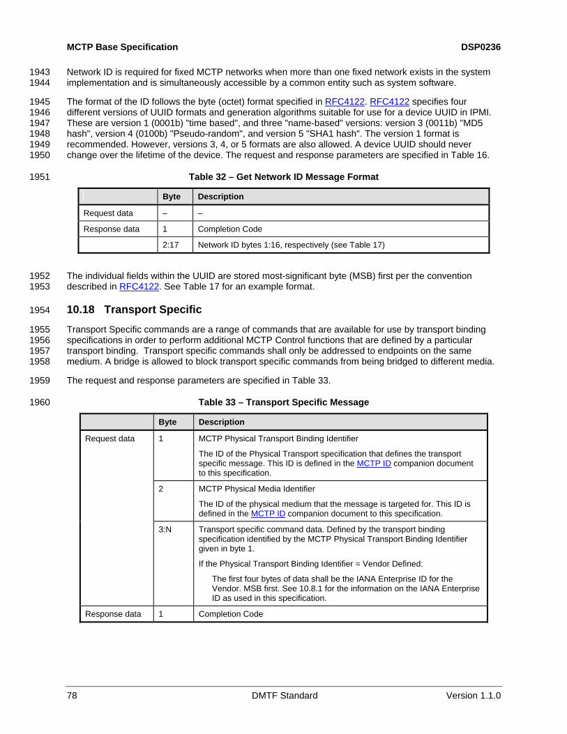
MCTP Base Specification DSP0236
78 DMTF Standard Version 1.1.0
Network ID is required for fixed MCTP networks when more than one fixed network exists in the system implementation and is simultaneously accessible by a common entity such as system software.
1943 1944
The format of the ID follows the byte (octet) format specified in RFC4122. RFC4122 specifies four different versions of UUID formats and generation algorithms suitable for use for a device UUID in IPMI. These are version 1 (0001b) "time based", and three "name-based" versions: version 3 (0011b) "MD5 hash", version 4 (0100b) "Pseudo-random", and version 5 "SHA1 hash". The version 1 format is recommended. However, versions 3, 4, or 5 formats are also allowed. A device UUID should never change over the lifetime of the device. The request and response parameters are specified in
1945 1946 1947 1948 1949 1950
1951
Table 16.
Table 32 – Get Network ID Message Format
Byte Description
Request data – –
Response data 1 Completion Code
2:17 Network ID bytes 1:16, respectively (see Table 17)
The individual fields within the UUID are stored most-significant byte (MSB) first per the convention described in
1952 RFC4122. See Table 17 for an example format. 1953
1955 1956 1957 1958
1959
1960
10.18 Transport Specific 1954
Transport Specific commands are a range of commands that are available for use by transport binding specifications in order to perform additional MCTP Control functions that are defined by a particular transport binding. Transport specific commands shall only be addressed to endpoints on the same medium. A bridge is allowed to block transport specific commands from being bridged to different media.
The request and response parameters are specified in Table 33.
Table 33 – Transport Specific Message
Byte Description
1 MCTP Physical Transport Binding Identifier
The ID of the Physical Transport specification that defines the transport specific message. This ID is defined in the MCTP ID companion document to this specification.
2 MCTP Physical Media Identifier
The ID of the physical medium that the message is targeted for. This ID is defined in the MCTP ID companion document to this specification.
Request data
3:N Transport specific command data. Defined by the transport binding specification identified by the MCTP Physical Transport Binding Identifier given in byte 1.
If the Physical Transport Binding Identifier = Vendor Defined:
The first four bytes of data shall be the IANA Enterprise ID for the Vendor. MSB first. See 10.8.1 for the information on the IANA Enterprise ID as used in this specification.
Response data 1 Completion Code

DSP0236 MCTP Base Specification
Version 1.1.0 DMTF Standard 79
11 Vendor Defined – PCI and Vendor Defined – IANA Messages 1961
The Vendor Defined – PCI and Vendor Defined – IANA message types provide a mechanism for providing an MCTP message namespace for vendor-specific messages over MCTP.
1962 1963
1964 1965 1966
1967 1968 1969 1970
1971 1972
1974 1975
1976
The PCI and IANA designations refer to the mechanism that is used to identify the vendor or organization this is specifying the message’s functionality and any parametric data or other fields provided in the message body.
Note that this specification only defines the initial bytes in the message body of these messages, and sets the requirement that these messages must follow the requirements set by the MCTP base protocol and any additional requirements necessary to meet the transport of these messages over a particular medium, such as path transmission unit limitations.
Otherwise, any other field definitions and higher level message behavior such as retries, error/completion codes, and so on, is message type-specific and thus is vendor-specific.
11.1 Vendor Defined – PCI Message Format 1973
For these messages, the MCTP message type is set to the value for "Vendor Defined – PCI" as defined in Table 3. The request and response parameters are specified in Table 34.
Table 34 – Vendor Defined – PCI Message Format
Byte Description
1:2 PCI/PCIe Vendor ID. Refer to PCIe. MSB first. This value is formatted per the Vendor Data Field for the PCI Express vendor ID format. See 10.8.1". NOTE: Because the vendor ID format is implied by the command, the Vendor ID
Format bytes are not part of this field.
Request data
(3:N) Vendor-Defined Message Body. 0 to N bytes.
1:2 PCI/PCIe Vendor ID. Refer to PCIe. MSB first. Response data
(3:M) Vendor-Defined Message Body. 0 to M bytes.
11.2 Vendor Defined – IANA Message Format 1977
For these messages, the MCTP message type is set to the value for "Vendor Defined – IANA" as defined in
1978 1979
1980
Table 3. The request and response parameters are specified in Table 35.
Table 35 – Vendor Defined – IANA Message Format
Byte Description
1:4 IANA Enterprise ID for Vendor. MSB first. This value is formatted per the Vendor Data Field for the IANA enterprise vendor ID format. See 10.8.1. NOTE: Because the vendor ID format is implied by the command, the Vendor ID Format bytes are not part of this field.
Request data
(5:N) Vendor-Defined Message Body. 0 to N bytes.
1:4 IANA Enterprise ID for the Vendor. MSB first. Response data
(5:M) Vendor-Defined Message Body. 0 to M bytes.
1981

MCTP Base Specification DSP0236
80 DMTF Standard Version 1.1.0
ANNEX A (informative)
Notation
1982 1983 1984 1985
1987
1988 1989 1990
1991 1992
1993 1994 1995
A.1 Notations 1986
Examples of notations used in this document are as follows:
• 2:N In field descriptions, this will typically be used to represent a range of byte offsets starting from byte two and continuing to and including byte N. The lowest offset is on the left, and the highest is on the right.
• (6) Parentheses around a single number can be used in message field descriptions to indicate a byte field that may be present or absent.
• (3:6) Parentheses around a field consisting of a range of bytes indicates the entire range may be present or absent. The lowest offset is on the left, and the highest is on the right.
• PCIe Underlined, blue text is typically used to indicate a reference to a document or specification called out in
1996 1997 1998
1999
2000 2001
2002 2003
2004 2005
2006
2007
2, "Normative References", or to items hyperlinked within the document.
• rsvd Abbreviation for Reserved. Case insensitive.
• [4] Square brackets around a number are typically used to indicate a bit offset. Bit offsets are given as zero-based values (that is, the least significant bit [LSb] offset = 0).
• [7:5] A range of bit offsets. The most-significant is on the left, and the least-significant is on the right.
• 1b The lower case "b" following a number consisting of 0s and 1s is used to indicate the number is being given in binary format.
• 0x12A A leading "0x" is used to indicate a number given in hexadecimal format.

DSP0236 MCTP Base Specification
Version 1.1.0 DMTF Standard 81
ANNEX B (informative)
Change Log
2008 2009 2010 2011 2012
Version Date Description
1.0.0 2009-07-28 Released as DMTF Standard 1.1.0 2010-04-22 Released as DMTF Standard, with the following changes:
• Updated the glossary and the overview section, including additions for MCTP host interfaces and descriptions of MCTP networks.
• Added support for MCTP network IDs and the Get Network ID command.
• Addressed Mantis issue: 0000417. • Added text to Clause 1 (Scope) referencing DSP0238 and
DSP0239 per WG ballot comments.
2013

MCTP Base Specification DSP0236
82 DMTF Standard Version 1.1.0
Bibliography 2014
2015 DMTF DSP2016, Management Component Transport Protocol (MCTP) Overview White Paper, http://www.dmtf.org/standards/published_documents/DSP2016.pdf 2016
2017 DMTF DSP4004, DMTF Release Process 2.2, http://www.dmtf.org/standards/published_documents/DSP4004_2.2.pdf 2018
2019