management, - pci.org resources/fib... · although the international federation for structural...
TRANSCRIPT


Management, maintenance and strengthening of
concrete structures
Technical report prepared by former FIP Commission 10
April 2002

Subject to priorities defined by the Steering Committee and the Praesidium, the results of fib’s work in Commissions and Task Groups are published in a continuously numbered series of technical publications called 'Bulletins'. The following categories are used:
category minimum approval procedure required prior to publication
Technical Report approved by a Task Group and the Chairpersons of the Commission State-of-Art report approved by a Commission Manual or Guide (to good practice)
approved by the Steering Committee of fib or its Publication Board
Recommendation approved by the Council of fib Model Code approved by the General Assembly of fib
Any publication not having met the above requirements will be clearly identified as preliminary draft.
This Bulletin N° 17 has been suggested as a fib technical report by the Editorial Group finalising the work that started in the former FIP Commission 10 Management, maintenance, and strengtening of concrete structures and has been recommended for publication by selected reviewers of fib Commission 5 Structural service life aspects.
The Editorial Group finalised the work of the former FIP Commission 10 Management, maintenance, and strengtening of concrete structures. CEB and FIP merged in 1998 into fib. This report, therefore, is published in the new fib series of bulletins. Members of FIP Commission 10 contributing to the work by preparing documents or by participating in one or more of the Commission meetings are indicated below:
Carmen Andrade (Spain), Hans Henrik Christensen* (Denmark, technical secretary of FIP Comm. 10), Stuart Curtis (Australia), Jean-Philippe Fuzier* (France), Enrique Gonzalez-Valle (Spain), Leif Q. Hartøft (Denmark, chairman of FIP Comm. 10), Marko Hranilovic (Croatia), Rob W. Irwin (New Zealand), Dieter Jungwirth (Germany), Sergio Lopes (Portugal), P. Y. Manjure (India), Zvonimir Maric (Croatia), Peter Matt (Switzerland), Stuart Matthews* (United Kingdom), Rod W. McGee (Australia), Tiago Mendonca (Portugal), Find Meyer (Denmark), Hans-R. Müller (Switzerland), J. B. Newman (United Kingdom), Christian Ottesen (Denmark), Elisabeth Schjølberg* (Norway), Zhuang Jun Sheng (China), Peter Van Meer (Sweden)
* Member of the Editorial Group finalising this document.
Full affiliation details of may be found in the fib Directory. Cover figure: Developed Tuutti Model, see Fig. 1-3 © fédération internationale du béton (fib), 2002 Although the International Federation for Structural Concrete fib - féderation internationale du béton - created from CEB and FIP, does its best to ensure that any information given is accurate, no liability or responsibility of any kind (including liability for negligence) is accepted in this respect by the organisation, its members, servants or agents. All rights reserved. No part of this publication may be reproduced, stored in a retrieval system, or transmitted in any form or by any means, electronic, mechanical, photocopying, recording, or otherwise, without prior written permission. First published 2002 by the International Federation for Structural Concrete (fib) Post address: Case Postale 88, CH-1015 Lausanne, Switzerland Street address: Federal Institute of Technology Lausanne - EPFL, Département Génie Civil Tel (+41.21) 693 2747, Fax (+41.21) 693 5884, E-mail [email protected], URL http://fib.epfl.ch ISSN 1562-3610 ISBN 2-88394-057-6 Printed by Sprint-Digital-Druck Stuttgart
fib Bulletin 17: Management, maintenance and strengthening of concrete structures iii
Foreword
This technical report is the result of the work of FIP Commission 10 Management, Maintenance and Strengthening of Concrete Structures established in autumn 1995 as the replacement / continuation of a previous FIP Commission Maintenance, Operation and Use which, at that time, among others due to personal reasons, had not been in action for a while.
In 1998 CEB and FIP were merged, forming fib. However it was agreed at that time to complete and take to an end the work of FIP Commission 10 which had been chaired by Leif Hartøft. This work was being done in close relationship with CEB Commission V Operation and Use and more particularly Task Group 5.4 Assessment, Maintenance and Repair with Julio Appleton as convenor.
The purpose of this report is twofold. Firstly, to give an overview of the issues relating to the management of concrete structures in general and, secondly, to supplement this with details on items concerned with assessment and remedial actions, as these are important technical parts of management and maintenance systems. The more general aspects of asset management are dealt with here in chapter 1 which is mainly aimed at owners and decision-makers. Chapters 2 and 3 concern the information required for decision making in the assessment process and are aimed more at consultants and contractors. A review of remediation techniques is given in chapter 3 which is intended to assist in the selection of remedial actions rather than their execution. The report also includes some significant appendices regarding load testing, monitoring, fire and last but not least concerning special considerations relating to seismic retrofitting.
It is worthwhile to mention also the work presented in Appendix 1 Keywords which should guide and encourage the various actors playing a role in this field to use a common language.
The Commission has had five meetings : in Copenhagen (Denmark), Croatia, London, Svolvaer (Norway) and in Sevilla (Spain). An Editorial Group has carried out the last part of the work on this report with several meetings in Oslo, Paris, Copenhagen and London.
The newly created fib Commission 5 dealing with Structural Service Life Aspects and chaired by Steen Rostam is now taking over the subject. Jean-Philippe Fuzier Chairman of the Editorial Group
Copyright fib, all rights reserved. This PDF copy of fib Bulletin 17 is intended for use and/or distribution only by National Member Groups of fib.

iv Contents
Contents 1 Management and maintenance 1.1 Management and maintenance - an integrated part of the life cycle cost concept 1 1.2 Important aspects of asset management 3 1.2.1 General 3 1.2.2 Deterioration mechanisms 4 1.2.3 Determination of required asset service life and safety level 5 1.2.4 Input to life cycle cost analyses 7 1.3 Management systems 8 1.3.1 General 8 1.3.2 Elements of the management system 11 1.3.3 Management tools 16 1.4 Environment and occupational health 17 2 Assessment 2.1 Introduction 19 2.2 Methodology 20 2.3 Existing documents and future plans 22 2.4 Inspections 2.4.1 Types of inspections 23 2.4.2 Routine inspections 25 2.5 Investigations 2.5.1 Introduction 28 2.5.2 Simple on-site testing 32 2.5.3 Non-destructive testing (NDT) techniques 34 2.5.4 Testing of material samples 39 2.5.5 Static load testing 40 2.5.6 Dynamic response measurements 41 2.5.7 Advantages and limitations of selected testing and inspection techniques 42 2.6 Re-calculation 2.6.1 Purpose of re-calculation 49 2.6.2 General approach 49 2.6.3 Safety concepts in general 50 2.6.4 Safety concepts in codes 51 2.6.5 Safety concepts for re-calculation 52 2.6.6 Calculation procedure 53 2.6.7 Basic input to re-calculations 53 2.6.8 Type of calculations 53 2.6.9 Probabilistic methods 56 2.7 Strategies for remedial actions 2.7.1 General approach 57 2.7.2 How to determine the optimal strategy? 59 3 Remedial actions 3.1 Introduction 61 3.2 Approach to selection of remedial actions 61 3.3 Alternative options 62 3.4 Surface protection 3.4.1 Surface impregnation and coatings 63 3.4.2 Bandaging and bridging cracks 66 3.4.3 Filling cracks 67
Copyright fib, all rights reserved. This PDF copy of fib Bulletin 17 is intended for use and/or distribution only by National Member Groups of fib.

fib - Bulletin 17: Management, maintenance and strengthening of concrete structures v
3.5 Repair 3.5.1 Concrete restoration 67 3.5.2 Preserving or restoring passivity of the reinforcement 70 3.5.3 Cathodic protection 73 3.6 Structural strengthening 3.6.1 Strengthening of concrete sections 75 3.6.2 Strengthening with bonded materials 76 3.6.3 Strengthening with additional prestressing 77 3.6.4 Miscellaneous 78 3.7 Demolition 3.7.1 Design and procedures 78 3.7.2 Demolition technologies 78 3.7.3 Recycling of materials 79 3.7.4 Selection criteria 79 4 Reporting 4.1 Type and purpose of report 81 4.2 General requirements for a report 81 4.3 Report structure and content 82 4.4 Process of preparing a report 84 5 Forward look 5.1 Socio-economics drivers for change 85 5.2 Management and maintenance issues 85 5.3 Assessment methodologies 85 5.4 Remedial actions 86 5.5 Co-ordination and standardisation 86 Bibliography 87 Appendices 1 Keywords 95 2 Deterioration and distress mechanisms 103 3 Inspection equipment list 111 4 Load testing 113 5 Monitoring 123 6 Fire 133 7 Special considerations relating to seismic retrofitting 153
Copyright fib, all rights reserved. This PDF copy of fib Bulletin 17 is intended for use and/or distribution only by National Member Groups of fib.

fib Bulletin 17: Management, maintenance and strengthening of concrete structures 1
1 Management and maintenance 1.1 Management and maintenance - an integrated part of the life cycle
cost concept Continuously increasing demands in society for economic growth and economic effi-
ciency, combined with increasing service and environmental requirements, have naturally had a major influence upon the construction and building industries. This has led to:
• An ever increasing rate of new construction • Introduction of new materials • Less conservative design and the adoption of new design concepts • More complex structures • Structures exposed to new and often severe environmental loads, the durability impli-
cations of which may not be fully understood at the time of design • More focus on new capital investments than upon the maintenance of existing struc-
tures • Loss of ‘old’ knowledge and expertise.
Lack of understanding of the consequences of these changes in practice has caused unpre-
dicted and serious deterioration problems, occasional collapse of structures and unexpectedly large investments in repair and strengthening works. These influences have affected most types of buildings and structures to some degree but possibly concrete structures to the great-est extent. At the same time the developed countries have recognised that the stock of existing structures represents a huge economic investment that cannot be easily replaced. The result of this has been an increasing recognition of the following:
1. the importance of durability; 2. the renewal cost of existing structures is so large that their replacement would not be
possible, and that it is essential that their useful life-span is maximised; 3. structures need to be inspected and assessed throughout their service life; 4. need for timely, reliable and systematic feedback upon in-service performance.
The response to these difficulties has included the development and implementation of
Management and maintenance systems (MMS) for assets and structures in order to: • Handle the necessary information flow and store relevant data • Plan and organise the maintenance activities • Prepare and manage maintenance budgets (cost control) • Design new structures for durable performance and long-life span.
Moreover, contemporary asset management philosophy is often to introduce an even
broader and more ‘holistic’ approach for the management of structures. The life cycle cost (LCC) concept considers and analyses the service life of structures ‘from concept to disposal’. It is self-evident that LCC analyses can only make a useful contribution if they utilise appro-priate modelling processes and that reliable input-data are available. For many structures the analysis of the performance in the service and operation period is crucial. Modern manage-ment and maintenance system consequently need to ensure that data are recorded in such a way that it satisfies the requirements for data to be used in the analysis and assessment proc-esses. Another development moving in the same direction is the introduction of automatic built-in monitoring systems combined with the development of intelligent information sys-tems.
Copyright fib, all rights reserved. This PDF copy of fib Bulletin 17 is intended for use and/or distribution only by National Member Groups of fib.
1 Management and maintenance 2
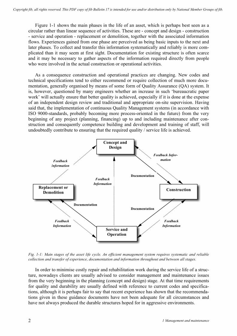
Figure 1-1 shows the main phases in the life of an asset, which is perhaps best seen as a circular rather than linear sequence of activities. These are - concept and design - construction - service and operation - replacement or demolition, together with the associated information flows. Experiences gained from one phase are perceived as being basic inputs to the next and later phases. To collect and transfer this information systematically and reliably is more com-plicated than it may seem at first sight. Documentation for existing structure is often scarce and it may be necessary to gather aspects of the information required directly from people who were involved in the actual construction or operational activities.
As a consequence construction and operational practices are changing. New codes and technical specifications tend to either recommend or require collection of much more docu-mentation, generally organised by means of some form of Quality Assurance (QA) system. It is, however, questioned by many engineers whether an increase in such ‘bureaucratic paper work’ will actually ensure that better quality is achieved, especially if it is done at the expense of an independent design review and traditional and appropriate on-site supervision. Having said that, the implementation of continuous Quality Management systems (in accordance with ISO 9000-standards, probably becoming more process-oriented in the future) from the very beginning of any project (planning, financing) up to and including maintenance after con-struction and consequently competence building and development and training of staff, will undoubtedly contribute to ensuring that the required quality / service life is achieved.
Fig. 1-1: Main stages of the asset life cycle. An efficient management system requires systematic and reliable collection and transfer of experience, documentation and information throughout and between all stages.
In order to minimise costly repair and rehabilitation work during the service life of a struc-ture, nowadays clients are usually advised to consider management and maintenance issues from the very beginning in the planning (concept and design) stage. At that time requirements for quality and durability are usually defined with reference to current codes and specifica-tions, although it is perhaps fair to say that recent experience has shown that the recommenda-tions given in these guidance documents have not been adequate for all circumstances and have not always produced the durable structures hoped for in aggressive environments.
Concept and Design
Service and Operation
Construction Replacement or Demolition
Documentation
Documentation Documentation
Feedback Infor-mation
Feedback Information
Feedback Information
Feedback Information
Feedback Information
Copyright fib, all rights reserved. This PDF copy of fib Bulletin 17 is intended for use and/or distribution only by National Member Groups of fib.

fib Bulletin 17: Management, maintenance and strengthening of concrete structures 3
However, it is clear from the activities included in the existing management and mainte-
nance systems that are introduced in the service and operation phase (see Fig. 1-2) that many systems are established only after deterioration problems have appeared. This practice will hopefully change in the future. Fig. 1-2: “Sub-cycle” activities related to service and operation 1.2 Important aspects of asset management 1.2.1 General
Management of assets is undertaken to ensure that those assets continue to perform their intended purpose and to maintain the owner’s investment. The need for sound asset manage-ment becomes more critical as the assets age, demands on assets increase and resources for their maintenance become increasingly constrained. The overall objectives of effective asset management are usually to:
1. maintain public and structural safety, 2. ensure that the functionality of structures is maintained at an acceptable level, 3. minimise total operating costs, 4. maintain the value of the asset, 5. maintain an acceptable aesthetic appearance
If one considers recent and ongoing technical research in the concrete field, it might be
concluded that the results have indeed provided a better understanding of aspects of the total service life performance of concrete structures and, consequently, of the composition of total life cycle costs. The research activities can be divided into the following two groups:
Service and Operation
Concept and Design
Construction
Repair and Rehabilitation
Replacement or Demolition
Inspection Detailed Assessment
Optimisation of Remediation
Strategies
Feedback Information
Copyright fib, all rights reserved. This PDF copy of fib Bulletin 17 is intended for use and/or distribution only by National Member Groups of fib.

1 Management and maintenance 4
a) General aspects • Development of models for LCC analysis • Development of models to describe environmental loads
b) Concrete structures
• Research on deterioration mechanisms • Development of models to describe the service life performance with regard to de-
terioration and wear mechanisms • Research and development of repair and remediation techniques.
1.2.2 Deterioration mechanisms
Much effort has been expended in understanding the mechanisms of deterioration, seeking to establish not only the reasons why deterioration takes place, but how damage develops and at what rate.
These issues are dealt with widely in the literature. An overview is given in Appendix 2. The mechanisms of deterioration are usually grouped as follows:
1. Reinforcement corrosion and corrosion of prestressing tendons - this usually results in
cracking of the concrete and reduction in load carrying capacity due to the reduction in the cross-section area of the reinforcement or prestressing strands. The main reasons for deterioration are that the protective qualities of the concrete are reduced due to:
• Carbonation of the concrete cover • Chloride attack • A combination of both mechanisms
2. Damage due to deterioration of the concrete matrix - there are a number of potential mechanisms, some of them associated with the composition of the concrete and some of them caused by environmental factors. In many instances the mechanisms are com-plex and may not be fully understood. The mechanisms which are encountered in most parts of the world include: • Alkali-aggregate reactions (AAR) • Sulfate attack • Delayed Ettringite formation • Micro - biological attack • Freeze - thaw
3. Physical damage, due to overloading, impact loads, abrasion , spalling etc. 4. Initial cracking and its effects.
The rate at which different forms of distress develop varies considerably from one area of
the structure to another, in addition it can also depend upon the type of asset. This can be a main factor to be dealt with by the maintenance system. The negative effects of the deteriora-tion might be reduced to an acceptable level if they are taken into account properly when planning the investment in the asset and designing the structure. Design and construction for durability is however not dealt with in detail in this report. But in general, structures shall be designed and detailed so that they can resist the environmental loads during service life and so that they are easy to inspect, maintain and repair at low costs. And construction specifications and practice shall be implemented respecting carefully the requirement related to the 'Four C’s of concrete': Concrete mix - Cover to reinforcement - Compaction - and Curing.
Copyright fib, all rights reserved. This PDF copy of fib Bulletin 17 is intended for use and/or distribution only by National Member Groups of fib.

fib Bulletin 17: Management, maintenance and strengthening of concrete structures 5
1.2.3 Determination of required asset service life and safety level “Service life” is a complex and indistinct concept, it is generally difficult to determine in
detail. Function, safety, aesthetics, economics and environment issues are amongst the range of factors that may in combination dictate the final service life. For some assets, heritage is-sues will be a major consideration. Required service life The minimum period during which the structure or specified part of it
should perform its design functions subject only to routine servicing and maintenance.
Design service life The anticipated time in service until an a-priori defined unacceptable state is reached.
Technical service life The time in service until a defined unacceptable state is reached. Functional service life The time in service until structure is functionally obsolete due to
changes in requirements. Economic service life The time in service until replacement is economically more advanta-
geous than continued maintenance in service.
The definition of an acceptable service life (= functional and economic service life) in the ‘concept and design’ phase is, to a large extent, dependent upon type of asset concerned. In many countries a service life of 100 years or more is required for structures such as bridges, while 40 years might be required for offshore structures. Modern office environments require flexibility in functionality and space occupation, building service provision and internal ac-cess. This means that the structural performance of the structure may be a secondary consid-eration compared with the requirements of the building users. If the building provides enough flexibility, it will be possible to accommodate their changing requirements without altering the structure. Thus, what is regarded as an acceptable service life varies considerably. It is, however, very important in the planning and design phase to define in details the criteria con-nected to required service life such as unacceptable technical states and service requirements as well as the basis for economic evaluations.
When considering service life it is important to consider what constitutes the end of serv-ice life. This could be taken as:
• the point at which corrosion is initiated, • the first appearance of cracking (visible with magnification), • cracking visible to the naked eye, • first spalling, • excessive deflection, • collapse under the design loading.
This approach to service life design does not result in a single value but recognises that it
may vary depending on a number of factors including the type of element or structure and the associated performance requirements, as well as on the maintenance regime that is to be adopted. In addition, environmental and aesthetic aspects can strongly influence considera-tions about what comprises acceptable technical performance and are parameters that may need to be addressed.
Service life design should also consider the ‘criticality’ – i.e. the seriousness of durability failure of the structure or element. Criticality of the element reflects its importance in load-
Copyright fib, all rights reserved. This PDF copy of fib Bulletin 17 is intended for use and/or distribution only by National Member Groups of fib.

1 Management and maintenance 6
carrying terms, the difficulty of repair/replacement and the consequential disruption. Struc-tures/elements could be categorised as low, medium or high criticality. High Life-long : failure would cause cessation of function and/or major disruption dur-
ing remedial work. Medium Efficiency of operation reduced but replacement/remedial work can be done dur-
ing normal working hours. Low Not critical. Maintenance/remedial work can be done without inconvenience.
The criticality of the element or structure will therefore determine the approach appropri-ate to its service life design. For structures where the consequences of failure are extremely high an approach based on risk minimisation will be most appropriate. In these cases the ini-tial and whole life concrete maintenance and repair costs are of less concern than the conse-quences of failure. Design options considered may involve the use of specialist design and protection strategies. In low criticality structures concrete mix designs, using information taken from current codes and standards, and associated guidance may be sufficient.
The Tuutti model provides one possible general description of how deterioration proc-esses may develop within a concrete structure. It defines:
• an initiation period; that is the period when no damage has developed in an asset (al-though the processes of deterioration may well be active),
• a propagation period; that is the period when damage is developing and propagating within the structure, and
• the service life time; as the period during which the structure fulfils the specified tech-nical requirements and associated (strength) requirements.
These concepts are illustrated by Figure 1-3. The Tuutti model was originally developed to
describe mechanisms of corrosion of reinforcement, but it might be applied (perhaps in a modified form – it would be probably more appropriate for the curve to be not linear) more widely to describe deterioration in general. Fig. 1-3: The Tuutti model and a “developed Tuutti model”. The Initiation period I is defined as the time until damage starts. In real structures this value may vary due to local variations in environmental loads, stresses and material characteristics.
Time/Age
I P Initiation
Period Propagation
Period
Technical Service Life
Accept limit
Damage Degree
Time/Age
Accept limit
Damage Degree
I1 I2
P2 P1
TT TT1 TT2
Copyright fib, all rights reserved. This PDF copy of fib Bulletin 17 is intended for use and/or distribution only by National Member Groups of fib.

fib Bulletin 17: Management, maintenance and strengthening of concrete structures 7
An increase in service life might be achieved by prolonging the initiation period or by de-creasing the rate of propagation once damage had started to occur, or by both. When seeking to adopt a remediation approach it is important to know whether the structure is in the initia-tion phase or in the propagation phase. Local variations in condition may cause difficulties in determining an appropriate repair technique. Figure 1-3 also illustrates the issue of local variations in condition.
The difficulty is to define the Initiation period I in a distinct way and then to predict the subsequent rate of propagation. This is particularly apparent in case of chloride initiated cor-rosion. Even where concrete properties are nominally identical, the rate of chloride penetra-tion varies within wide limits, especially in a marine environment. At the moment, it is not possible to estimate the initiation time I, nor the rate of propagation with sufficient accuracy. Corrosion caused by carbonation is often more predictable. Recent research activities have concentrated upon these issues. It is possible to set up fairly sophisticated models of these de-terioration mechanisms. At the moment, these deterioration models are not automatically in-corporated in the management systems. However they are often used in support of technical decisions.
Occasionally the deterioration of the structure will prejudice the safety of its users or that of the general public. The overall safety of a structure is usually evaluated by comparing the ratio between the actual load effects and the resistance to withstand these loads. It is a func-tion of the knowledge of the mechanical properties of the actual structure and the service situation, but is also affected by the type of analysis, which is performed 1. In the evaluation of safety these calculations may take into account statistical uncertainties in a more or a less advanced way. During the lifetime of a structure, the actual safety level will usually decrease due to material deterioration, or perhaps because of an increase in load level (a situation commonly encountered with bridges). 1.2.4 Input to life-cycle cost analyses Having identified the deterioration mechanisms, it should be possible to make a life cycle cost analysis. However, there are other parameters that will influence the results. Asset costs will undoubtedly vary dependent on the asset type. Economic modelling needs to involve the de-termination of all costs attributable to each stage is an asset’s life cycle. Thus, the concept and design stage might include costs related to: Feasibility studies, research, planning, program-ming, functional and detailed design and documentation. In the construction stage: Tendering, fabrication, construction, contract administration, quality control, quality assurance and fi-nancing all contribute to the costs. Some of the cost contributions in the Service and Opera-tion stage and the Disposal stage are shown in Table 1-1.
Operation Maintenance Disposal Examples of cost Operations personnel Asset management Decommissioning contributions Supervision Inspection/investigation Demolition Training Maintenance personnel Sale Energy Maintenance activities Site rehabilitation User costs Spares Decontamination Training
Table 1-1: Activities in service and operation and disposal stages that might influence the life-cycle cost. 1 The safety level is usually defined implicitly in the national codes and related to local experience. As the national codes have different safety philosophies, it is difficult to compare safety levels directly between countries. The codes are made to ensure an acceptable safety level in the view of the public and society. An estimation of the safety of the structure by calculations will never reflect the actual safety level precisely. However, sophisticated probabilistic methods have now been developed and are available. This makes it possible to make an estimate of the actual level of safety in a more “deterministic” way.
Copyright fib, all rights reserved. This PDF copy of fib Bulletin 17 is intended for use and/or distribution only by National Member Groups of fib.

1 Management and maintenance 8
In addition to financial considerations there are also those associated with environmental factors.
One should be aware of the fact that as the structure life cycle proceeds through the con-cept and design, construction, operation and use and the disposal phases, the influence on life cycle costs is progressively reduced as conceptualised in Figure 1-4. This emphasises the im-portance of the concept and design and planning phases.
Fig. 1-4: Influence of main phases in asset life upon total life-cycle costs
The same principles are expressed in the well known “de Sitter’s Law of Five’s”: ‘$1 spent getting the structure designed and built correctly, is as effective as $5 spent in subse-quent preventative maintenance in the pre-corrosion phase while carbonation and chlorides are penetrating inwards towards the steel reinforcement. In addition, this $1 is as effective as $25 spent in repair and maintenance when local active corrosion is taking place, and this is as effective as $125 spent where generalised corrosion is taking place and where major repairs are necessary, possibly including replacement of complete members. 1.3 Management systems 1.3.1 General 1.3.1.1 Introduction
Notwithstanding that management systems need to combine and coordinate a wide range of disciplines as indicated in Figure 2.5, the level of sophistication of an asset management system should be tailored to the size and complexity of the asset being managed. Owners of small numbers of well built structures in benign environments are only likely to need a basic management system, which could perhaps even be paper based. The sophistication of the management system will need to increase as the complexity of the asset increases. Factors in-dicating the need for a more sophisticated system include the number of structures, their geo-graphical spread, their range of environmental exposures, structural complexity, their critical-ity for public safety, any deterioration in condition, the numbers of people involved in man-agement, mechanisms of accountability in decision making, consequences of loss of function and requirements for information on the asset.
The requirements for systems to manage assets need to be carefully defined in order that the system is suitable for the intended purpose. Recent experience and developments in the field suggest that there may be benefits in procuring (as opposed to developing) an appropri-ate system at acceptable cost and should be considered.
Copyright fib, all rights reserved. This PDF copy of fib Bulletin 17 is intended for use and/or distribution only by National Member Groups of fib.

Management Policy
Deterioration Mechanisms and
Service Life Prediction
Construction for Durability
Minimum Life Cycle
Costs
Design for Durability
Optimal Maintenance
Inspection and Assessment
Optimisation of
Remediation Strategies
Budgeting and Planning
Execution of Preventive and Remedial Works
Requirements Implications
Analyses
Routine Inspections
Basic Testing
Investigations and Testing
Re-calculation
Monitoring
Remediation Techniques
Tools
Administration Safety
Service
Aesthetics
Environ-ment
Fig. 1-5: Relationship between Requirements, Minimum Life Cycle Costs, Management and Maintenance Activities
• Improved Technology • Quality Management • Quality Assurance Proc-
essing • Certification Systems • Competence Building
and Development • Training of Staff
Occupati-onal Health and Safety
Copyright fib, all rights reserved. This PDF copy of fib Bulletin 17 is intended for use and/or distribution only by National Member Groups of fib.

1 Management and maintenance 10
This is especially so for certain types of structures - such as bridges - where the concepts of asset management have been applied most widely. For special or particular types of struc-tures, it may be necessary to develop an appropriate system. Most systems are “frames or shells” - their main purpose is to organise information. The decision on the nature of the in-formation required should always be based upon local needs.
The benefit and success of a management system for individual concrete structures, as well as for a collection of structures, depends upon:
1. A suitable integration of the management system for the actual structures into the overall general management system employed by the organisation managing the asset.
2. The reliability and relevance of the recorded data. 3. Simplicity. 4. A stepwise implementation.
1.3.1.2 Risk assessment
Management systems developed based on risk assessment might be a more common variant in the future. Tools for risk based management systems are under development, but to
How can it happen?
Determine
likelihood
Establish level of risk
The organisational contest
The risk management context
Decide the structureDevelop criteria
Compare against criteria
Set risk priorities
Identify treatment options
Evaluate treatment options
Prepare treatment plans
Implement plan
What can happen?
The strategic context
ESTABLISH THE CONTEXT
IDENTIFY RISKS
ANALYSE RISKS
Determine existing controls
ASSESS RISK
TREAT RISK
Determine
consequences
MONITOR
REVIEW
AND
Fig. 1-6: Risk Management Process
Copyright fib, all rights reserved. This PDF copy of fib Bulletin 17 is intended for use and/or distribution only by National Member Groups of fib.

fib Bulletin 17: Management, maintenance and strengthening of concrete structures 11
date experience is limited, at least when talking about ordinary structures. In Figure 1-6, a flowchart related to this approach is shown (from the Australian standard). A risk based man-agement approach is mainly aimed at large structures or large stocks of more or less similar structures.
The analysis of risk needs to consider both the likelihood and consequences of the identi-fied risks. The variability in deterioration processes, loading and other aspects of structural behaviour mean that there will be uncertainty in assessing aspects of structural performance. Risks will be not only related to structural integrity, but may also include a lack of load capac-ity, inefficiency, obsolescence, an inadequate level of service or redundancy. Treatment op-tions may involve continuation of or variation to an existing maintenance regime, rehabilita-tion, strengthening, replacement, disposal, demand management, reductions in the level of service or doing nothing. It is not easy to calculate risk accurately on a general level. 1.3.1.3 Economic analysis and financial modelling
Economic analyses are an important part of a management system. This will typically be undertaken using discounted cash flow methods to calculate net present values of various management strategies. For government assets, discount rates will generally be similar to long term bond rates. This discount rate varies between countries, normally within the range 5 - 10%. Because of the long lives generally expected of concrete structures and the effects of discounting on the present value of future cash flows, careful consideration needs to be given to the consequences of deferring maintenance and the potential availability of funds at the time that expenditures are likely to be incurred.
Other techniques include life cycle costing and average annual costs.
Priority based on estimated cost and financial modelling are important elements of man-agement systems. Financial modelling involves the use of inventory and condition data and deterioration models to: • Develop maintenance, rehabilitation and replacement needs • Determine budget needs • Optimise expenditures within budgets • Assess the implications of various budget scenarios on asset condition.
More sophisticated systems will consider user costs, such as the costs of delays or detours
associated with bridge closures, in the financial modelling. 1.3.2 Elements of the management system 1.3.2.1 Introduction
Elements of a basic management system will include: • Descriptions of structures, including location, dimensions, materials and date of con-
struction • Condition of structural elements • Maintenance, rehabilitation and replacement needs, including estimated costs and pri-
orities.
Copyright fib, all rights reserved. This PDF copy of fib Bulletin 17 is intended for use and/or distribution only by National Member Groups of fib.

1 Management and maintenance 12
As the degree of sophistication of the management system increases, the following com-ponents may be added:
• Deterioration models, • Optimisation modules, • Planning modules.
The number of elements in an asset management system and their complexity will depend
upon the factors described previously and may include: • Inventory data, • Condition data and deterioration modelling, • Maintenance, rehabilitation and replacement needs, • Usage data, • Maintenance histories.
The various elements are described in more details below. The condition data is the most
critical factor of the management system, as the collection includes several uncertainties. Re-cording may range from manual documentation to computerised databases and asset man-agement systems. 1.3.2.2 Inventory
Inventory data is that which remains essentially unchanged for the life of the structure or until it is upgraded. It may include:
Shall always be included Shall be considered • Name • Identifying description, number • Location • Title information • Design parameters, including loading • Materials of construction • Description of environment • Year built • Design life • Restrictions on use, such as load and clearance limits on
bridges • References to relevant documentation, including drawings,
design calculations, construction records, operation and maintenance manuals, and files relating to the structure.
• Descriptions of compo-nents
• Design, construction and replacement costs
• Effective life • Service installations,
such as electricity, tele-communications and water
• Direct and indirect costs of failure
• Probabilities of failure • Failure mechanisms
Asset registers may be linked to other organisational databases and geographic informa-
tion systems. This should not be a difficult part of the management system - theoretically. It is typical, however, for recorded data to contain inaccuracies. 1.3.2.3 Condition data
Inspection or monitoring of asset condition is an integral essential part of asset manage-ment, with the following objectives:
• to ensure public safety • to monitor asset condition
Copyright fib, all rights reserved. This PDF copy of fib Bulletin 17 is intended for use and/or distribution only by National Member Groups of fib.

fib Bulletin 17: Management, maintenance and strengthening of concrete structures 13
• to monitor the performance of various structural components and materials • to provide feedback to design, construction and maintenance personnel • to identify deficiencies to facilitate timely intervention • to determine maintenance, rehabilitation and replacement needs • to establish a history of performance • to determine the consumption of an asset and its residual life expectancy.
Monitoring and inspections are discussed more in details in chapter 2. At the moment in-
service monitoring is mainly introduced only in special cases. Inspections are the essential part of any management and maintenance system and require definition and determination of following important parameters:
• Type and nature of inspection • Frequency and extent of inspections • Qualifications and experience of the inspectors • Reliability of recorded data.
The type and nature, extent and frequency of inspections will depend upon a number of
factors including: 1 The environment in which the structure is located and deterioration mechanisms con-
cerned 2 Asset type, which includes parameters such as:
• the importance of the structure, • the level of risk to the public and the consequences of failure.
3 The condition of the structure, which depends on the following parameters: • the age of the structure, • loading history, • physical state including any alterations or strengthening, • amount and extent of damage.
4 The materials used in its construction 5 Maintenance
• type, • frequency, • repair history.
There are a number of different approaches to the set-up of inspections and different phi-
losophies have been developed for inspection routines. In chapter 2 one suggestion is given.
When defining the inspection frequency, points 1-3 above should be considered as the most important; while points 4-5 would influence the nature and type of the inspections. 1.3.2.4 Determination of inspection frequency
Considering environment, asset type and asset condition as the most important factors, one may use the following “Relative Inspection Frequency” (RIF) concept as a simplified ap-proach for determining the inspection frequency. It is suggested that assets be categorised into three “asset groups” reflecting criticality, these being: low, medium and high. Figure 1-7 shows how the environment, condition and asset criticality might influence the relative in-spection frequency.
Copyright fib, all rights reserved. This PDF copy of fib Bulletin 17 is intended for use and/or distribution only by National Member Groups of fib.

1 Management and maintenance 14
Consider, for example, environment as a main factor when seeking to define inspection frequency. If a structure is in a marine or other severe environment, the inspection frequency should be higher than if the structure is located in a dry climate or other generally benign cir-cumstances. If the asset is complex and the consequences of poor maintenance are significant, one should have more frequent inspections than if the asset stock is small and the structures concerned are simple.
Marine /poor Wet /
medium Dry /good
Low
Medium
High
0
2
4
6
8
10
Inspection
Frequency
Environment / condition
Assetcriticality
RIF(A,E): Asset criticality - Environment / condition
Low
Medium
High
Fig. 1-7: RIF as function of asset criticality and environment / condition
The condition of the asset is another important factor, which should influence the inspec-tion frequency. If the risk of collapse is increasing while the asset is still in use, continuous monitoring or frequent inspections might be considered an appropriate regime.
The final inspection frequency may be determined by combining the different RIFs. As a guide, structures in good condition in benign environments should undergo a routine inspec-tion2 at intervals not exceeding three - ten years. The frequency might increase to perhaps an-nually or six-monthly for older structures in poor condition and in aggressive environments. 1.3.2.5 Type of inspections
The most cost-efficient and important inspection method is visual inspection, which quickly provides an overview of the condition of the structure and makes it possible to report back immediately. It is the cheapest inspection type and, with experienced staff, it is also suf-ficient reliable. This is indicated in Figure 1-8. It is postulated that approximately 80% of relevant information can be provided by visual inspections for approximately 20% of the total inspection costs. Volume of Relevant Information Costs Fig. 1-8: The importance of visual inspections
2 This depends on how routine inspection is defined! In some countries a routine inspection is somewhere between the “ad-hoc” and “routine” inspections mentioned in chapter 2.
20% 80%~ Visual
Inspections
Copyright fib, all rights reserved. This PDF copy of fib Bulletin 17 is intended for use and/or distribution only by National Member Groups of fib.

fib Bulletin 17: Management, maintenance and strengthening of concrete structures 15
So far it has not been proved cost-effective to substitute partial or total visual inspections by test or other measurement methods. Available methods are not simple and tend to be ex-pensive if used extensively. Data processing and interpretation of the results may also be a complex matter. Accordingly such methods are typically used in special inspections and are targeted to obtain specific items of information that are required in the assessment procedure. Significant improvements are expected in this field in due course, but visual inspection proce-dures are expected to remain important for the foreseeable future.
Additional inspections to the visual inspections may be required when a damage is re-ported or when there is a proposed change in usage. If the damage is substantial or if death or injury has occurred, there may be special requirements related to the collection of evidence and preservation of the scene. Close liaison with police, fire and ambulance personnel may be required in such circumstances.
Inspections need to be undertaken by appropriately qualified and experienced personnel, with the requirements increasing with the level of sophistication of the inspection. The impor-tance of this factor should not be underestimated. Lack of relevant experience and appropriate training often results in inaccurate recording of data. This in turn may result in misunder-standings concerning condition and wrong decisions regarding remedial actions and mainte-nance needs.
An efficient inspection requires proper preparation, including review of existing documen-tation. It also requires the results of the inspection to be properly and systematic documented and stored.
For basic asset management systems, descriptive reporting of condition may be used, with supporting photographs as appropriate. For computer-based systems numerical condition rat-ing is usually essential, with objective descriptions of various ratings required to ensure con-sistency between inspectors and inspections.
Structural assessment may also be required and involve an analysis of a structure to evalu-ate its load capacity, making use of inventory, condition and usage data. It is likely to be un-dertaken where deterioration in condition or changes in usage indicate that the structure may no longer be capable of fully undertaking its required function. Deficiencies may also arise where design loadings are revised (e.g. earthquake, temperature) or where loads increase (e.g. permitted maximum size of truck or axle weight, change in use of a building). In addition to the use of numerical condition rating systems, deterioration modelling may be used to repre-sent and predict the deterioration of structures and the effectiveness of various remedial op-tions. 1.3.2.6 Maintenance, rehabilitation and replacement needs and options
Outputs from inspections and assessments of a structure become inputs into maintenance, rehabilitation and replacement strategies. The processing of assessing options needs to con-sider the causes and extent of any deficiencies and the likely success of available remedial techniques.
Options for implementation cannot however be considered in isolation, but will need to consider the requirements of other structures within an asset inventory and any related techni-cal, financial, economic, social and political factors. Non-structural options, such as demand management, also need to be considered.
Copyright fib, all rights reserved. This PDF copy of fib Bulletin 17 is intended for use and/or distribution only by National Member Groups of fib.

1 Management and maintenance 16
1.3.2.7 Usage data
Monitoring of the usage of assets is an integral approach for ensuring they are serving their intended purpose. The level of data will be dependent upon the size and nature of the asset and its usage, but may include: - Example from a road authority:
• Vehicle volumes, including temporal distributions, • Types of vehicles, • Mass distributions of vehicle,
- Type of loading in buildings (office, storage, etc.), - Projected changes in usage. 1.3.2.8 Maintenance histories
The recording of maintenance histories of structures is an integral part of effective asset management:
• Surface protection • Repairs • Rehabilitation • etc …
1.3.3 Management tools
Two basic types of management systems have been developed: 1. For individual structures 2. For population of structures as an aid to the prioritisation of the resources among them.
When developing or purchasing a management system, the following parameters in table 1-2 should be considered. 1.4 Environment and occupational health
Environment and occupational health and safety are aspects that need to be considered se-riously. Effects of structures on the environment may need to be assessed for reasons includ-ing compliance with relevant legislation. ISO 14000 provides one framework for such as-sessments. One should be aware of the increasing interest concerning health occupation. As many materials used in repair and maintenance operations might be toxic, this is focused in an increasing number of countries.
Hazards may include: • the need to work in high and/or exposed locations in varying weather conditions, • construction and maintenance processes, • the alkalinity of cementitious materials, • irritant, toxic or carcinogenic properties of other materials, • construction and maintenance vehicles, • traffic using the structure.
Copyright fib, all rights reserved. This PDF copy of fib Bulletin 17 is intended for use and/or distribution only by National Member Groups of fib.

fib Bulletin 17: Management, maintenance and strengthening of concrete structures 17
Parameters Comments The level of sophistication re-quired
“Simple is beautiful” - few structures will benefit from a high degree of sophistication. Structures that need to be monitored continuously might benefit from a more sophisticated MMS. In-house compe-tence is needed if you have complex structures and/or a structure in “severe” environment - how-ever expert know-how might be bought from outside.
Investment required to implement a system.
Costs for in-house development are normally under-estimated. An overall global analysis is required if you have a complex asset or assets with high criti-cality. If you have a small asset or assets of low im-portance, and are considering buying a MMS, a fixed price should be asked for.
Computing system requirements Capabilities of existing systems to meet the owner’s needs
Capabilities of the development organisation in the type of assets being managed
Technical support for prioritisation systems, including future devel-opment of the system
Consideration depends on in-house competence, and the asset importance. If you have no in-house com-petence, this is an important factor.
Satisfaction of other system users References should always be collected and scruti-nised.
Costs of purchase and maintenance of the system
Occupational health and safety
Effective management of structures involves proper consideration of occupational health and safety for persons involved in construction, inspection, main-tenance and operation.
Table 1-2: Factors to be considered if a proprietary Management and Maintenance System is to be purchased.
Management of the risks associated with those hazards may include: • the provision of personal protective equipment, • the provision of suitable access equipment, • the provision of first aid equipment and trained personnel, • traffic management, • the development of work procedures, • compliance with materials safety data sheets for hazardous materials, • use of alternative less hazardous materials , • training of personnel, • containment of waste.
Copyright fib, all rights reserved. This PDF copy of fib Bulletin 17 is intended for use and/or distribution only by National Member Groups of fib.

fib Bulletin 17: Management, maintenance and strengthening of concrete structures 19
2 Assessment 2.1 Introduction
The objective of this section is to introduce and present procedures for assessment of con-crete structures. Detailed information on specific test procedures is not provided, but the main aspects of the tests and their interpretation are presented.
The assessment is a complex interaction between: • structural, environmental and service data, • data from existing documents, • data from visual inspection, • test data from in-situ and laboratory investigations, • consideration of potential remedial actions.
Assessment of an existing concrete structure can comprise the following activities: • planning of assessment activities, comprising gathering of information about the his-
tory of the structure, first visit, programming the activities, proposal, contracting; • routine (standard, initial, regular) inspection, consisting of visual inspection, basic
testing, reporting and simple condition evaluation and planning a detailed investiga-tion if necessary;
• detailed investigations: examination and special testing of materials and deterioration phenomena for assessment of safety, durability and prediction of corrosion progress;
• special tests and investigations: structure response testing, measuring true actions on the structure;
• deterioration assessment based on routine inspections and detailed investigations: o for concrete: categorisation of degraded areas on the structure, o for reinforcement and prestressing: degree and rate of corrosion, residual
prestressing forces; • structural assessment based on special tests and investigations: real carrying capacity
and estimation of safety, prediction of the remaining service life, adequacy rating;
The activity flow of the assessment procedure is shown in figure 2-1, which also shows the links to the overall management system including planning, budgeting and optimisation.
The scope of programmed activities will depend on the severity and extend of the ob-served condition, and of the significance of the structure.
Reinforced and prestressed concrete structures should be assessed:
a) if required by the user or owner of the structure • in case that the reliability of the structure is jeopardised because of concrete and
reinforcement deterioration; • when additional loads should be carried by the structure; • to gather necessary data for the design of repair and upgrading.
b) on a regular basis, as generally carried out for large stocks of structures of large num-bers of components e.g. for road and railway bridges
• to safeguard the safety and serviceability (functionality) under normal operation conditions;
• to create the database of updated information about the condition of every struc-ture of a stock as the basis for making decisions about necessary maintenance measures;
Copyright fib, all rights reserved. This PDF copy of fib Bulletin 17 is intended for use and/or distribution only by National Member Groups of fib.

2 Assessment 20
• to establish priorities for the repair, rehabilitation or replacement of heavily dete-riorated structures.
The assessment of concrete structures should only be carried out by a team of experts un-
der the guidance and coordination of an experienced structural engineer.
Basic Testing
Monitoring
Routine
Inspection
Condition
Rating
Repair Needs
Budgeting and
Planning
Execution of
Works
Management and
Maintenance Policy
Optimisation
Detailed
Assessment
Remediation
Strategies
Investigations
and Testing
Re-calculation
Monitoring
Remediation
Techniques
Fig. 2-1: Main activities of the assessment procedure for concrete structures in a management and maintenance system (refer Figure 1-5)
2.2 Methodology
The objective of the engineer is to provide the client with clear information so that he can decide what actions to be taken. A typical work sequence may include following activities:
1. Preparation 2. Inspection 3. Investigation 4. Recalculation 5. Strategies for remedial actions 6. Reporting
Based upon the approval of the report and the recommended proposal for remedial actions,
the detailed design for remedial works is carried out including technical specifications.
Copyright fib, all rights reserved. This PDF copy of fib Bulletin 17 is intended for use and/or distribution only by National Member Groups of fib.

fib Bulletin 17: Management, maintenance and strengthening of concrete structures 21
Preparation Proper preparation and planning are basic requirements to be met in order to carry out pro-
fessional assessment of any defective structure. It includes: • Getting all the existing information about the structure, relevant to the assessment. • In case the information from regular routine inspections is not sufficiently detailed to
pay a first visit to the structure. In any case, it is fundamental to provide a preliminary understanding of the structure, its site conditions and visual deterioration.
• The planning of the assessment according to the Client’s concern and objectives. At this stage it is necessary to establish an overview with typical regions of deterioration or environment/structure conditions and to prepare a test programme with representa-tive tests in order to reduce the amount of work.
Inspections
The visual inspection is the fundamental basis for providing a life time monitoring and understanding of the structure, its site conditions and visual deterioration. In a routine inspec-tion the identification of the main mechanisms of deterioration should be established.
This section deals with the routine inspection consisting of the following aspects: • visual inspection and the way to select the information, • supplementary basic testing programme for structures where specific deterioration
mechanisms are expected to take place. Such a programme can consist of measure-ment of concrete cover depths and reinforcement location, carbonation depth and content and distribution of chlorides and crack survey and mapping.
From the results of the routine inspection and basic testing and identification of the main
mechanism of deterioration, a planning of the detailed investigations can be done if found necessary. Investigations
The objective is to understand the causes of deterioration and to establish its degree and consequences for the structure safety and durability.
At this stage three types of tests are to be performed in case of a corrosion problem: - tests to establish the concrete and steel properties related to mechanical and durability
aspects ; - tests to establish the actual corrosion of reinforcement and/or prestressing and its corro-
sion rate ; - tests to assess the structure global response.
Recalculation
Once a clear understanding of the causes and of the degree of deterioration is obtained, a recalculation of the structure can be carried out and an assessment can be proposed.
The recalculation may cover several aspects: - evaluation of current service conditions - evaluation of the remaining carrying capacity - evaluation of the deterioration progress - service life prediction.
As a result of an assessment possible restrictions in normal use can be introduced or the
need for an intervention pointed out as an urgent or required measure.
Copyright fib, all rights reserved. This PDF copy of fib Bulletin 17 is intended for use and/or distribution only by National Member Groups of fib.

2 Assessment 22
Strategies for Remedial Actions The results of the assessment form the basis for analyses of different alternatives and
strategies for remedial actions taking into account actual and future requirements and costs. Finally, the most economic solution is chosen based upon a more or less sophisticated optimi-sation of available funds. Reporting
The results of the routine inspection should be presented in a standard reporting format. The report should include:
• recording of the main damages including evaluation of cause of the damages, • condition rating marks for the elements of the structure and the structure as a whole, • recommendations for remedial repair works and routine maintenance, • overview photos and detailed photos of main damages.
The results of the detailed investigations and the assessment should be reported in a clear
and objective way in the assessment report. The location of tests and mapping of deterioration is to be presented graphically. Each test result is to be referred to the test specification and used to being presented in details in an appendix. Supporting structural calculations and serv-ice life analyses may be included in appendices as well. The report shall present the main conclusions, interpretation of test results and prediction of remaining service life in a clear and understandable way for the client / owner.
Report on repair and rehabilitation proposals including economic (feasibility) analyses and cost estimates may be included in the assessment report or reported separately. 2.3 Existing documents and future plans General
The process of carrying out an appraisal of a concrete structure requires the identification and the evaluation of information existing about the structure concerned coupled with an as-sessment of the nature and extent of additional information required to complete the task. In the case of a deteriorating concrete structure, the appraisal will undoubtedly require some form of inspection or testing to define the mechanism(s) and severity of structurally signifi-cant degradation. The process of appraisal, particularly of a deteriorated concrete structure, is likely to involve a number of cycles of gathering and evaluating information.
Gathering of existing information about a structure and its material properties may involve searching a number of potential sources of information. It is unusual for the appraising engi-neer to be presented with a dossier containing a complete description of the original structure as built and of subsequent alterations and repairs. Information can be gathered from the struc-ture but much time, money and disruption can be avoided if appropriate documentary infor-mation is available and reliable. Gathering information
Much useful information about the form of the structure is contained in the documents prepared for its original design and construction. Documents concerning subsequent modifi-cations and repairs will provide an insight into the history, use, maintenance and problems encountered with the structure in service. Generally the engineer will have to search for this information.
Copyright fib, all rights reserved. This PDF copy of fib Bulletin 17 is intended for use and/or distribution only by National Member Groups of fib.

fib Bulletin 17: Management, maintenance and strengthening of concrete structures 23
In addition to information about the form of the structure and subsequent modifications, knowledge is required about the environmental and loading conditions to which the structure has been exposed in service or may be exposed to in the future.
Documents relating to the particular structure under consideration may take a number of forms and include:
• drawings of the structure as-proposed or as-built, the latter being preferable, giving dimensional and construction details, structural arrangements and materials used in construction;
• calculations; • specifications and bills of quantities; • articles in technical journals or the press about prestigious structures; • applications for planning or building control requirements; • maintenance schedules or reports; • technical log for structure; • photographs.
Potential sources for such a documentary information may include : • the owner of the structure; • professional advisers to the owner / occupier(s) / user(s); • original structural designer or other members of the design team; • contractors (original and repair / refurbishment organisations); • structural subcontractors (e.g. Suppliers of precast components); • design team for repair / refurbishment works; • building control authority; • public record offices and institutional archives for prestigious structures.
In addition to information about the specific structure being considered, there is generally
a large volume of supplementary explanatory information which covers systems of construc-tion, codes of practice, contemporary advice and guidance notes, testbooks and papers and associated matters such as patents. This type of information is most likely to be available from professional institutions and specialised sources such as research establishments, trade asso-ciations, libraries and manufacturers. Future Plans
When setting up and preparing repair and rehabilitation strategies it is essential and very important to collect all existing information from the Owner(s), the Users and all relevant Authorities regarding Future Plans for the structure in question. Proper strategies can only be set up and concluded upon based on such necessary information and further negotiations with the parties involved and predictions on additional future requirements. 2.4 Inspections 2.4.1 Types of inspections
Inspections can be divided in two main categories:
I. Ad hoc inspections Ad hoc inspections are typically carried out irregularly and in connection with events not directly related to the condition and performance of the structure. Such
Copyright fib, all rights reserved. This PDF copy of fib Bulletin 17 is intended for use and/or distribution only by National Member Groups of fib.

2 Assessment 24
event could be selling / buying, change of user, change in function, inspection of installations and utilities etc. Ad hoc inspections are usually seen in housing and office buildings, factories and buildings aimed for production facilities. For such structures however, regular in-spections may have been introduced for certain parts of the structure such as the ex-terior (outdoor) parts supposed to be exposed to a more aggressive environment. The same is valid for indoor structures placed in an aggressive environment.
II. Inspections integrated in Management and Maintenance Systems (MMS)
MMS-integrated inspections usually form a complex of different types of inspec-tions that supplement each other. The activities and procedures for such inspections are usually described in details in Manuals.
In the following, mainly MMS-integrated inspections are considered, but several proce-
dures described can be implemented for Ad hoc inspections as well. MMS-integrated inspec-tions may be divided into three main groups:
1. Superficial Inspections 2. Routine Inspections which may be supplemented by Basic Testing (and Monitoring) 3. Detailed Investigations
and defined roughly as follows: 1. Superficial Inspections: Visual inspections, carried out frequently by maintenance
staff/squads in connection with their main duties. The aim is to “catch” serious and sudden arisen defects related either to the function or the structure safety, which are immediately reported to the Administration. These inspections are not carried out by professionals, i.e. not structural engineers, and no assessment is carried out.
2. Routine Inspections (or Principa l /General Inspections): Regular systematic inspections carried out by professionals (structural engineers) in order to visually assess the condition of all elements of the structure, the deterioration rate, the need of repair and need of further detailed investigations. The result of the work is a report with selected photos or video stills, which will be a part of the chronology of the structure and form the main basis for planning of future remedial works.
3. Basic Testing: For structures placed in an aggressive environment, or for structures where specific deterioration mechanisms are expected to take place, the routine inspection may be supplemented by a basic testing programme to monitor the initiation process, refer chapter 1.2.3. For an example it can consist of measurements of concrete cover depths and rein-forcement location, carbonation depth and content, distribution of chlorides and crack sur-vey and mapping.
4. Detailed investigations which are described in details in chapter 2.5 are carried out only on special request, i.e. if the structure is in poor condition either caused by deterioration or there is a worry that serious structural defects may exist, or if the structure for other rea-sons need to be reconstructed or strengthened and there is a need of stating the condition in details. Detailed investigations are also initiated in case of special incidents, such as earth-quakes, flooding, explosions etc. This work is carried out by specialists, who can handle the special testing equipment needed for such investigations and who are able to interpret the results of these investigations. The aim of the detailed investigations is to define the cause of the damage, the deterioration mechanism, and the extent of the damage and to es-
Copyright fib, all rights reserved. This PDF copy of fib Bulletin 17 is intended for use and/or distribution only by National Member Groups of fib.

fib Bulletin 17: Management, maintenance and strengthening of concrete structures 25
timate the future rate or development of the damage. A detailed report is usually prepared based on the test results.
Reference is made to Appendix 6 regarding assessment of concrete structures damaged by
fire and Appendix 7 regarding assessment of concrete structures damaged by seismic actions. 2.4.2 Routine inspections 2.4.2.1 Purpose and content
Regular routine inspections of structures form the main basis - technically and economi-cally - for planning of the necessary maintenance and repair activities for each specific struc-ture and a stock of structures in order to meet the function and safety requirements of the structure(s) at any time in the most cost-optimal way. Besides that, regular routine inspections gives the owner a tool to record ‘continuously’ the condition development of the structures.
The basis of the routine inspections is a systematic - mainly visual - evaluation of the con-dition of each element of the structure. The first principal inspection is carried out just after the completion of the construction works, and may be defined as the Reference Condition of the structure. The next inspections are carried in intervals of say for example 3-6 years de-pendent on the condition of the structure. For elements placed in very severe environment or exposed to high load levels or in increasingly poor condition, inspections may be carried out more frequently.
The routine inspection includes: • Condition evaluation of all elements of the structure and of the structure as a whole. • Assessment of type and extent of the main damages seen. • Evaluation of the quality of the maintenance. • Evaluation of the need of remedial repair works: type of repair, price estimate, optimal
time of execution. • Necessity of detailed investigations. If costly remedial works are expected to be car-
ried out, a detailed investigation is normally recommended. • Time for next inspection.
2.4.2.2 Preparation
Following information shall be gathered before the inspection is carried out: • Structure identification. • Previous inspection reports and reports on previous repair works. • Analyses of safety for the inspection staff during the execution of the inspections. • Receive the necessary approvals and permits from other authorities for carrying out the
inspections. • Determine the basis time period for evaluation of possible remedial works to be con-
sidered. • Define the limit between superficial repair works and remedial works. • Define criteria for inspection intervals.
The routine inspections shall follow a specific procedure, so that the latest inspection re-
sults can be compared directly with those from previous inspections and inspections results from other structures. The following basis documents shall be available when the specific inspection is carried out:
Copyright fib, all rights reserved. This PDF copy of fib Bulletin 17 is intended for use and/or distribution only by National Member Groups of fib.

2 Assessment 26
• the inventory data for the structure, • the chronology, • main drawings (plan, elevation, cross-sections), • list of elements of the structure, • previous inspection reports, • list of routine maintenance works, • inspection procedure for the specific structure in question in case such one is available, • repair strategy for the structure, if available.
The equipment needed for the inspection may vary dependent of type of structure, but can
be divided into the following main groups: 1. Safety equipment for the staff. 2. Inspection equipment and basic tools. 3. Supplementary safety and inspection tools.
In Appendix 3, a list of typical equipment for visual inspection and simple on-site testing
is shown. Prior to the inspection, the safety requirements related to inspection of each element shall be analysed. For example may extra light sources and fresh air equipment be needed. Due to difficult accessibility for some of the elements, special lifts or similar accessories may be required for the inspection. 2.4.2.3 Division into elements
It is recommended to divide the structure into elements as shown in the following example from an ordinary bridge structure:
1. The entire structure 2. Wing walls 3. Slopes 4. Abutments 5. Intermediate supports 6. Bearings 7. Carrying superstructure 8. Waterproofing 9. Edge beams 10. Crash barriers and railings 11. Surfacing 12. Expansion joints 13. Other elements
A suitable division into elements normally both reflects the type of structure and typical
damage patterns. For larger and more complex structures, a more detailed element list is nor-mally required. Some (secondary) elements may be included separately due to the fact that they are especially exposed to deterioration or other impacts. 2.4.2.4 Procedure
It is strongly recommended that the inspection is carried out in a systematic way element by element. Preferably, a specific sequence should be given in a manual, and should only be deviated from in case of obstacles. The first activity on site of the inspection is to prepare a preliminary overview of the structure and the condition of the structure. Based on that, the sequence of the inspection is decided.
Copyright fib, all rights reserved. This PDF copy of fib Bulletin 17 is intended for use and/or distribution only by National Member Groups of fib.

fib Bulletin 17: Management, maintenance and strengthening of concrete structures 27
The manual shall also include guidelines or check lists for what to look after for each spe-cific element.
The inspection engineer shall evaluate the condition of each specified element with regard to the damage seen and cause of this damage and each element shall be given a condition rat-ing mark, see below.
Further, the need for a detailed investigation is evaluated and reported in case of serious deterioration damage or suspicious behaviour. The quality of the routine maintenance is evaluated as well. If remedial repair works are considered necessary, the repair method and procedure, a cost estimate and the optimal time of execution is reported. The cost estimate is usually prepared based on a Price Catalogue with updated average prices on standard repair works which normally forms a part of a MMS. 2.4.2.5 Assessment of damage
All damage seen shall be assessed, but it is recommended that only the main damage is re-ported. If the reporting is too detailed, the overview may be lost, and experience says that such detailed information collected is normally not useful in practice. A main damage is defined as:
1. One that forms a potential risk for the user or influences/disturbs or interrupts the function of the structure,
2. One that may require repair or replacement now and in the future, 3. One that may imply subsequent damage, 4. One where monitoring is recommended due to the uncertainty of the type, cause and
development rate of damage.
In the report, a short description of the damage and the location is given. It is strongly rec-ommended to include in the manual, standard descriptions/notations of element types, stan-dard notations for locations and standard grouping of the damage and cause of damage. In the report, the description of the main damage should normally be supported by photos or video stills. 2.4.2.6 Condition rating
For structures that are maintained in accordance with the guidelines of MMS, each ele-ment of the structure is given a condition rating mark, and usually also the entire structure is given a mark as well. This procedure may be appropriate for a number of (other types of) structures not included in MMS as well.
The condition rating mark can be composed in different ways, but usually following con-tributions are taken into account:
• Evaluation of nature, cause and extent of the damages seen for the element (the main contribution to the rating mark is based on this evaluation),
• Influence of the damage on function of the structure, • Consequence of the damage to other elements.
Based on these contributions, a total rating mark is given. Different scales may be used in
the condition rating. One example of a scale may be one which is running from mark 0 to 5, with 0 reflecting none or insignificant damages, while 5 reflects very poor condition of the element and that urgent remedial actions are required.
Copyright fib, all rights reserved. This PDF copy of fib Bulletin 17 is intended for use and/or distribution only by National Member Groups of fib.

2 Assessment 28
The inspection guidelines in the manual should include a number of examples of how to
carry out the condition rating, so that ratings are carried out uniformly. 2.4.2.7 Time for next inspection
The time for the next inspection is determined based on the actual condition of the struc-ture and the expected rate of deterioration of the damages seen.
If major repair works are recommended as a result of the inspection, it is advisable to re-quire the next inspection to take place in due time before the estimated time of execution of these works, say 2 years before. Hereby, a re-evaluation of the recommended works can be done and the time for carrying out the necessary detailed investigations in order to define the amount of works and select the optimal strategy can be decided 2.5 Investigations 2.5.1 Introduction
Testing may be classified as being either routine or diagnostic in purpose. Many concrete structures are not included within management programmes which call for their routine in-spection and, accordingly, most testing will be of a diagnostic nature.
National standards, codes of practice and other forms of guidance document exist (or are being developed) which concern the execution of many of the testing and inspection proce-dures described in this document. It is not practicable to provide a comprehensive listing of all such sources and any such listing would soon be outdated by subsequent developments and revisions. The decision has been made not to cite such documents, but to leave the reader to research specific national requirements and related sources of guidance. This document limits itself to the broader principles associated with the selection of such testing and inspection procedures. Objectives of Testing
There are many different ways and reasons for testing concrete structures. Typical reasons include:
• where there is insufficient information about the nature and properties of the structure • where deterioration or deleterious materials are suspected • where an assessment of future service life is to be undertaken, or some aspect thereof • where it is necessary to confirm assumptions made for analysis or about in-service per-
formance.
The tests shall also provide the necessary input for choosing the optimal repair method and strategy. When to Test
Typically testing will not be considered until a desk study of available information and a preliminary visual inspection has been made of the structure. These steps would be expected to establish the objectives for the testing and how the information obtained might be expected to contribute to the overall decision making process. There are various circumstances where there may be no need to conduct detailed testing, including when:
• adequate details of the construction of the structure are available, • the structure is clearly in a sound condition with no deterioration apparent or antici-
Copyright fib, all rights reserved. This PDF copy of fib Bulletin 17 is intended for use and/or distribution only by National Member Groups of fib.

fib Bulletin 17: Management, maintenance and strengthening of concrete structures 29
pated, • the structure is in an extremely deteriorated condition and is obviously unfit for con-
tinued service, • lower-bound estimates of strength or section size provide satisfactory structural per-
formance, • the results of particular tests are unlikely to affect the outcome of the investigation.
Similarly there is little advantage in embarking upon a programme of testing if its cost is
likely to be a significant proportion of that of a remedial works scheme that could have been adopted initially, without the benefit of the information which would be derived from the test-ing. Thus for testing to be adopted it must offer some overall technical or economic advan-tage. Available test techniques cover a wide range of cost and complexity. It should also be recognised that some tests cause little disturbance to the fabric and users of the structure, whilst others involve major disruption and need much more careful planning if they are to be undertaken. Types of Tests
Tests can be divided into : • those which provide purely local information, such as the measurement of a dimen-
sion, spot tests for material composition, properties or integrity, and • those giving a direct indication of the performance of the structure, such as load tests
and dynamic response measurements.
Whilst these tests are generally referred to as being non-destructive, they may be of a par-tially-destructive (causing minor amounts of superficial damage or interference to the struc-ture, such as in the recovery of material samples for laboratory testing) or a truly non-destructive nature. In the latter category tests or inspection procedures (such as subsurface radar and ultrasound methods) are often referred to as being non-invasive.
In some circumstances it is appropriate for many spot tests to be performed and the results mapped to give a better appreciation of the variation of some particular characteristic across the structure, as is often done with ultrasound pulse velocity (UPV), depth of cover, subsur-face radar, electropotential and similar measurements. The mapping approach provides an overview and it can be adopted for almost any measurable or observable parameter.
Local tests and observations are typically undertaken to provide information : • upon strength of materials, • to clarify construction details, • to make comparative assessments of quality or condition (UPV, electropotential meas-
urement, etc.), • to identify mechanisms of deterioration, • to assess future durability, • to form the basis for choosing the optimal repair method and strategy.
Use of Complementary Testing Techniques
It is unlikely that the methods taken individually will provide a definitive answer to the questions posed and it will often be necessary to use a number of techniques or inspection procedures which provide complementary information. Acting in conjunction the different techniques will generally be better able to provide the breadth of information sought in most investigations, such as establishing the reasons for the deterioration observed. If testing and inspections are being undertaken to assess the condition of a structure or investigate some
Copyright fib, all rights reserved. This PDF copy of fib Bulletin 17 is intended for use and/or distribution only by National Member Groups of fib.

2 Assessment 30
form of deterioration, it should also be remembered that such surveys provide a ‘snap-shot’ detailing the circumstances at that time and that repeat surveys may be required at future times to monitor the development and rate of any deterioration. Targeting of Testing
It is more effective if testing effort can be targeted at what are anticipated to be critical pa-rameters and locations, rather than adopting a widespread and random approach to enable general conclusions to be drawn by means of statistical analysis. This assumes that such loca-tions can be determined in advance; a requirement which demands that the work be carried out by appropriately experienced personnel and that there is some a priori knowledge about the structure and its service history. Specialist advice may be needed when planning a testing programme. Phasing of Testing
Accordingly testing regimes are often developed in a phased or incremental manner so that the planning of later phases of an investigation can benefit from the findings of earlier investigation, inspection and assessment work. Because testing is generally an expensive process, it is necessary to carefully target the types of testing undertaken, the number of re-sults sought and to focus upon those locations which might be critical. It is essential that the information required from the testing regime is clearly identified at the outset. Consideration needs to be given to the:
• extent of possible variations of the properties of the concrete placed within individual members and used throughout the structure, as well as in the environment to which it has been exposed,
• limitations of the testing and inspection procedures adopted, • difficulties associated with undertaking the selected tests, their reliability and variabil-
ity, • equipment calibration requirements, particularly where on-site calibration is necessary, • interpretation of the test results and any problems which this may pose.
This document makes a division between “simple on-site testing”, “non-destructive test-
ing” and the “testing of material samples”, with the latter being undertaken in a recognised laboratory. The division between the first two categories of on-site tests cannot be absolute, it is simply intended to recognise broad differences in the complexity of the testing instrumenta-tion, the interpretation of the results, the levels of expertise and knowledge required to per-form the tests, amongst other factors. This document provides an overview of the application of these procedures. Readers who seek more detailed descriptions of the use of the various techniques and their interpretation are referred to the literature cited in the bibliography. Those documents also contain extensive lists of further references. Selection of Testing Techniques The following table provides a simplified guide for the initial selection of testing procedures:
Information sought Diagnostic testing or inspection technique Strength / surface hardness. 1. Near-surface properties of concrete :
− Cored samples : examination and crushing, etc. − Penetration resistance tests (Windsor probe). − Break-off tests. − Internal fracture tests. − Pull-off tests − Rebound hammer.
2. Representing properties of body of concrete : − Cored samples : examination and crushing, etc.
Copyright fib, all rights reserved. This PDF copy of fib Bulletin 17 is intended for use and/or distribution only by National Member Groups of fib.

fib Bulletin 17: Management, maintenance and strengthening of concrete structures 31
Information sought Diagnostic testing or inspection technique − Ultrasonic pulse velocity.
Comparative quality / uniformity of concrete.
1. Near-surface properties of concrete : − Cored samples : examination and crushing, etc. − Ultrasonic pulse velocity. − Rebound hammer.
2. Representing properties of body of concrete : − Cored samples : examination and crushing, etc. − Ultrasonic pulse velocity. − Impact echo tests. − Radiography.
Presence of reinforcement and depth of cover.
− Covermeter. − Subsurface radar. − Physical exposure by excavation or cored sample.
Presence of (steel) tendon duct or other metal object deeply embedded within concrete.
− Subsurface radar. − Pulse echo tests.
Depth of carbonation. − Phenolphthalein test (not applicable to High Alumina Cement (HAC) concretes).
− Petrographic / microscopic analysis. Presence of chlorides and chloride profiles. Presence of sulfates.
Drilled, lump or cored samples for presence of contaminant by laboratory analysis; incremental sampling required for profile determination. Site chemical tests (HACH, QUANTAB, RCT, etc) performed on drillings.
Reinforcement corrosion. Condition of embedded steel rein-forcement / prestressing tendons.
− Electro-potential mapping. − Resistivity evaluation. − Physical exposure by excavation or coring.
Corrosion rate. − Linear polarisation resistance. − Galvanic current measurement.
Extent and significance of cracking and visible defects.
− Visual inspection / photographic records.
Delamination. − Sounding surveys (tapping, chain drag, etc). − Examination of cored samples. − Thermography. − Impact echo tests. − Ultrasonic pulse velocity. − Subsurface radar.
Material properties : Concrete, steel, etc.
Material samples for laboratory inspection and testing for strength and other mechanical properties, physical or chemical make-up, condition, durability, etc.
Moisture content. − Direct (lab) measurement from lump sample. − Direct site measurement upon drilled dust sample using a chemical rea-
gent and calorimeter. − Resistance / capacitance / dew-point probes. − Subsurface radar (relative indication). − Thermography (relative indication)..
Abrasion resistance. − Accelerated wearing test. Alkali-silica reactivity. − Petrographic / microscopic analysis to identify.
− Laboratory tests for latent expansion properties. Grouting of post-tensioning tendon ducts / corrosion or other damage to prestressing tendon within duct.
− Physical exposure by excavation or coring, coupled with an air test to estimate void volume.
− Borescope or optical viewer inspection. − Radiography.
Surface permeability / absorption. − Surface absorption test (ISAT). − Water and gas permeability tests. − Absorption tests on intact cored samples.
Freeze - thaw − Petrographic / microscopic analysis to identify − Laboratory tests
Copyright fib, all rights reserved. This PDF copy of fib Bulletin 17 is intended for use and/or distribution only by National Member Groups of fib.

2 Assessment 32
Health and Safety Considerations When planning an investigation, account should be taken of the nature of the structure or
building and the appropriate equipment and clothing which may be necessary. In general, in-vestigations should not be carried out by people working on their own. If work is carried out alone, a system of reporting in at specified intervals should be adopted.
Dilapidated structures or confined spaces may constitute particular hazards; perhaps due to the build up of animal droppings, contamination, dust from previous activities and the like. Plant rooms, pipework lagging and defective services may present special hazards. It is possi-ble that parts of some structures may have been used by squatters or have been vandalised, with a subsequent effect upon their condition. Before embarking upon an inspection or testing activities, it is wise to make a general assessment of the state of the structure and only when satisfied that it is reasonably safe proceed with the proposed activity.
Site tests carried out as part of a reconnaissance visit tend to have limited objectives be-cause there has generally been restricted opportunity to prepare for the visit. Accordingly the site works often focus upon the need to gather data from readily accessible areas of the struc-ture. Objectives for such initial testing might include a limited number of spot checks to sup-plement visual inspections and dimensional surveys. 2.5.2 Simple on-site testing
The underlying concept of simple on-site testing is that it may be useful to have the capa-bility to perform a limited number of basic tests during preliminary or reconnaissance visits to site. The objective of performing such tests is to be able to obtain at an early stage some basic information upon the degree and extent of prevailing deterioration phenomena. In some struc-tures the requirements for inspections and testing may not extend beyond such basic testing. It is possible that experienced practitioners would start their investigation utilising some of these tests, whereas others might consider it appropriate to undertake a visual survey as a separate first step.
It is envisaged that appraising engineers who are appropriately trained, experienced and resourced would be able to undertake many of the basic tests themselves. Indeed over recent years it has become far more common for appraising engineers to have access to relatively sophisticated test instruments. However, it is necessary to sound a note of warning. Whilst modern equipment has become much easier to use and more automated, making it corre-spondingly simpler to generate sets of numbers which generally represent the variation in some measurable parameter across the structure or individual elements therein, there is still considerable scope for the inappropriate application of such equipment. There may also be appreciable difficulty in interpreting what the variations in the measured parameter actually represented. If the user has limited knowledge and experience of the equipment and the asso-ciated testing procedure, they may not appreciate its limitations and any restrictions which should be placed upon the circumstances in which it is applied.
The focus of the tests is likely to be different for different types of structures and different types of environments; e. g. carbonation of cover concrete is not usually a problem in prestresssed concrete structures because of the high strength and quality of the concrete mix employed. For simple or basic testing the types of tests and observations involved might in-clude reinforcement location, estimation of depths of cover and carbonation, drillings for chloride profiles; as well as the mapping of defects, delaminations, cracks and other relevant
Copyright fib, all rights reserved. This PDF copy of fib Bulletin 17 is intended for use and/or distribution only by National Member Groups of fib.

fib Bulletin 17: Management, maintenance and strengthening of concrete structures 33
visible features. These are described in more detail below. The information obtained from such basic testing will be of assistance in planning later phases of an investigation.
Site tests carried out as part of a reconnaissance visit tend to have limited objectives be-cause there has generally been restricted opportunity to prepare for the visit. Accordingly the site works often focus upon the need to gather data from readily accessible areas of the struc-ture. Objectives for such initial testing might include a limited number of spot checks to sup-plement visual inspections and dimensional surveys. 2.5.2.1 Defect mapping
A comprehensive investigation of a deteriorated concrete structure will include the map-ping of identifiable defects and the locations where other test procedures are performed. De-fects could potentially include:
• cracking; • scaling - local flaking or peeling away of the surface portion of hardened concrete or
mortar; • spalling - concrete fragments, usually detached from the parent concrete; • efflorescence - deposition of white salts or lime mortar on the concrete surface; • rust staining - brown or rust coloured stains; • weathering - changes in properties, such as colour, texture or strength; • honeycombing - clear evidence of voids or spaces between the coarse aggregate parti-
cles; • dampness - wet or moist areas of concrete; • joint leakage - generally water, but possibly contaminated with chlorides or other sub-
stances; • previous repairs - condition of previous repairs; • abrasion - progressive loss of mass from the concrete surface; • physical damage, such as vehicle impact; • delamination - detected by hammer or chain drag.
2.5.2.2 Measurement of crack development
Crack development over a period of time can be measured using various methods includ-ing optical equipment and electrical strain gauges. The Demec gauge, a mechanical strain gauge, is another simple way to measure crack movements with studs fixed permanently on either side of appropriate cracks. The measurement of crack movement is important in estab-lishing whether a crack is live or not, so that the appropriate repair method can be adopted. 2.5.2.3 Reinforcement location and depth of cover survey by covermeter
The depth of cover concrete, size and location of reinforcement can be estimated using electromagnetic covermeters. Although the equipment is straightforward to use, considerable care and skill can be required to obtain acceptable results. In heavily reinforced members it may not be possible to obtain reliable results. The performance of some equipment may be affected by low temperatures (<0oC), and mixes containing puzzolans (especially fly ashes), sands and crushed rock aggregate where they contain particles of magnetite. Some modern equipment can be connected to a data logger. Cover surveys need to be correlated with other elements of the investigation, including defect mapping, carbonation depths and chloride pro-files. Subsurface radar may also be used to estimate the depth of cover to reinforcement - see below.
Copyright fib, all rights reserved. This PDF copy of fib Bulletin 17 is intended for use and/or distribution only by National Member Groups of fib.
2 Assessment 34
2.5.2.4 Depth of carbonation survey
The depth of carbonation in ordinary Portland cement (OPC) concretes can be estimated by use of use of an indicator solution, such as phenolphthalein, sprayed onto a freshly ex-posed concrete surface. The indicator solution can be applied either to a freshly broken sur-face or, where this is not available, either progressively into an incrementally drilled hole or progressively onto the powder produced from such a drilling. This monitors the reduction in pH associated with the ingress of acidic atmospheric gases, such as carbon dioxide. Alkaline zones are identified by a purple red coloration, whilst the carbonated concrete remains uncol-oured when sprayed with phenolphthalein solution. In the vicinity of cracking and other sur-face defects, carbonation progresses to greater depths. The tests are easy and quick to per-form, surface damage is minor. 2.5.2.5 Chloride content and chloride profile (or other contaminant)
Powder samples obtained by percussive drilling or lump samples of concrete can be sent for laboratory analysis to determine the presence or otherwise of selected contaminants, such as chlorides and sulphates. When a structure is thought to be exposed to chlorides (e. g. in a marine environment or arising from de-icing salts) and it is necessary to establish chloride penetration profiles at selected locations on a structure, samples must be obtained from differ-ent depths below the surface of the concrete. This can be achieved by either incremental per-cussive drilling, or from cored samples which are subsequently cut into sections and ground up for laboratory chemical analysis. It should be noted that in some circumstances a local in-crease in the chloride content maybe present in the vicinity of the carbonation front.
There are a number of commercially available kits (for example, the Hach, RCT and Quantab methods available in the UK) for determining chloride contents from drilled sam-ples. The tests are generally straightforward and quick to perform (30 minutes). It is neces-sary to have facilities for sample preparation. Where there is a significant chloride content, the tests are generally of sufficient accuracy to indicate its presence and its approximate concen-tration. However, it is considered prudent for these indications to be backed up a proportion of laboratory based determinations.
The sampling regime must be carefully designed for the particular structure and the nature of the envisaged contamination (ie. introduced at the time of construction or subsequently by ingress). Field tests provide the flexibility to amend the sampling regime in light of the results obtained. 2.5.3 Non-destructive testing (NDT) techniques 2.5.3.1 In-situ compressive strength
A number of partially-destructive and non-destructive tests are available to measure the surface hardness of concrete and hence predict strength. Perhaps the most commonly used device is the non-destructive rebound hammer called the Schmidt Hammer. In new construc-tion the results can be calibrated against test cubes. The readings are susceptible to local variations and at least nine readings should be taken at each test location to obtain a represen-tative mean. The results are influenced by various factors including carbonation of the con-crete surface, which increases the hardness of this layer, invalidating strength calibration curves derived for new concrete.
Other tests include penetration resistance tests (Windsor Probe), pull-off tests, internal fracture tests and break-off tests.
Copyright fib, all rights reserved. This PDF copy of fib Bulletin 17 is intended for use and/or distribution only by National Member Groups of fib.

fib Bulletin 17: Management, maintenance and strengthening of concrete structures 35
The Windsor Probe test involves firing a hardened steel pin into the surface of the con-crete using a standard powder cartridge; the depth of pin penetration provides an empirical estimate of compressive strength, uniformity and quality of concrete. Performance is inde-pendent of the operator. One test result is obtained from a group of 3 pins. The main influ-ences upon penetration are aggregate type and surface hardness, so therefore the age of the concrete is also significant. Appropriate calibration charts are required for a particular mate-rial, aggregate and mix design. Pins should be positioned more than 50 mm from reinforcing bars and edges of the material. Larger diameter pins are used for lightweight concretes. The test causes surface damage.
The internal fracture and pull-off tests seek to provide a measure of the compressive strength of concrete by inducing internal fracture within the material. This can be achieved in a number of ways which are classified as either ‘pull-out tests’, where an anchor is inserted into the concrete, or ‘pull-off tests’ where a disk is bonded to the concrete surface. These are simple techniques requiring only light equipment. The test does cause some minor damage to the surface which will require repair. Good surface preparation is required with the ‘pull-off tests’ and there will be a delay (24 hr) whilst the adhesive hardens. Dampness can affect the bond achieved. Compressive strength is estimated from calibration charts and multiple tests are required to obtain a result.
The break-off test (Norwegian method) involves applying a transverse force by means of a hydraulic load cell to the top of a core formed by diamond coring 70 mm into the surface of the concrete member under test. The method provides an estimate of flexural tensile strength of the concrete. It is suggested that a result is taken as the mean of five test values. Correla-tion with compressive strength is less reliable that tensile strength correlation. Test is inex-pensive and quick to perform, but remedial repairs are required to the concrete surface. There is some concern about reliability of the test when it is performed without the benefit of spe-cific calibration data.
All these methods may be appreciably less accurate than the testing of cores recovered
from the structure, being affected by the various factors noted above. 2.5.3.2 Ultrasonic pulse velocity
The ultrasonic pulse velocity technique measures the speed of travel of a pulse of ultra-sound through concrete. It is used for relative assessment, that is in different members or along a given member, of strength and the detection of imperfections such as voids, delamina-tion, under-compaction and honeycombing. Calibration against concrete of known strength does improve the accuracy of the estimation of strength. Access is generally required to op-posite faces of the member under test. The technique requires precise measurement of the dis-tance between the two ultrasonic heads. The presence of steel reinforcement and moisture can affect pulse velocity values and need to be considered when interpreting test results. Range may be limited, but can be extended by using lower frequency transducers; although this re-duces resolution and discrimination of internal features. In large structures it may be neces-sary to employ an audio frequency pulse to obtain adequate range. 2.5.3.3 Half-cell potential surveys
The measurement of half-cell potentials is the most widely used method for assessing the likelihood of the corrosion of steel reinforcement in concrete. The technique involves measur-ing the electrical potential of embedded reinforcing steel relative to a reference half-cell (gen-erally copper - copper sulphate) placed on concrete surface to give an indication of the risk of
Copyright fib, all rights reserved. This PDF copy of fib Bulletin 17 is intended for use and/or distribution only by National Member Groups of fib.

2 Assessment 36
corrosion of the reinforcement. The results are plotted on potential contour maps. The tech-nique is susceptible to weather conditions, which may markedly influence the absolute values of electrical potential. Care has to be exercised to ensure satisfactory electrical coupling with the concrete pore fluids. Although the method provides an indication of localised zones of po-tential corrosion activity, it does not determine corrosion rates or the degree of corrosion which has occurred. The interpretation of half-cell potentials with respect to corrosion is cov-ered by various publications including ASTM C876-87, TRL Application Guide 9 and that from RILEM TC-154 (in preparation). 2.5.3.4 Resistivity
Concrete resistivity is a measure of the ability of the concrete to act as an electrolyte and carry corrosion currents. It is usually used to investigate areas of greatest corrosion risk identi-fied by electrical potential mapping, although by no means as widely. The technique meas-ures resistivity of the concrete surface layer by either 2 or 4 probe (Wenner) methods. In the case of the latter approach, four equally spaced probes are embedded in the surface of the concrete and a current is passed between the outer electrodes and the potential difference measured between the inner probes; enabling an estimate of resistivity to be made. The meas-urements give an indication of the rate of corrosion where the reinforcement is no longer pas-sive and, when used in conjunction with a half-cell potential survey, its likely extent. The technique does not give any guide as to the degree of corrosion damage that has taken place. 2.5.3.5 Linear polarisation resistance
Polarisation resistance measurements provide an indication of the rate of corrosion of metal embedded in concrete. Measurement of polarisation resistance involves applying a small potential shift and measuring the resulting current flow, enabling an estimate of the cor-rosion current to be made. Various designs of equipment are employed. In the simplest appli-cation two nominally equivalent electrodes are used. Some systems incorporate a third elec-trode in which the electrode of interest (working electrode) is measured relative to a reference electrode as in a half-cell potential measurement and the third electrode (auxiliary) is used simply to complete the circuit to allow current flow. A major difficulty with measurements made from the surface of the concrete is defining the area of embedded metal (reinforcement) which is participating in the measurement. One approach adopted to overcome this is to con-fine the measurement to a known area by the use of a guard ring electrode. The interpretation of these measurements is covered by various publications and that from RILEM TC-154 (in preparation). 2.5.3.6 Galvanic current measurement
Galvanic interactions occur when a corrosion cell is set up between two different metals or between similar metals in different electrochemical environments, such as carbon reinforcing steel in chloride contaminated concrete and in uncontaminated concrete. The galvanic or macro cell current which flows between the corroding anode and the passive cathode can be measured through an external connection. Whilst such data gives a clear indication whether corrosion has been initiated, it may be difficult to make an estimate the rate of corrosion of the reinforcement. The interpretation of these measurements is covered by various publica-tions and that from RILEM TC-154 (in preparation). 2.5.3.7 Impact echo
The test involves the propagation of an ultrasonic stress wave through the body of a con-crete element and the detection of energy reflected back to the surface, providing information upon member thickness and the presence of major internal voids, delaminations or other de-
Copyright fib, all rights reserved. This PDF copy of fib Bulletin 17 is intended for use and/or distribution only by National Member Groups of fib.

fib Bulletin 17: Management, maintenance and strengthening of concrete structures 37
fects. Mapping of the results enables the existence of thickness variations and the location and extent of defects to be established. The stress wave is typically generated by a single impact on the surface from a specialised hammer. Calibration of the velocity of propagation is neces-sary to obtain absolute determinations of thickness variations and depths to internal features, otherwise comparisons are made on a relative basis. 2.5.3.8 Subsurface radar
High frequency (0.1 - 1GHz) electromagnetic impulses are transmitted from an antenna traversed over the surface under investigation. Reflections are received from internal features and discrete boundaries between materials having different electrical and dielectric properties. The equipment is relatively expensive and requires experienced personnel to operate it and interpret the results. Whilst the technique can be very powerful, it works best in simple planar forms of construction such as slab structures. Access is required to only one face of a struc-ture element when the radar is operated in reflection mode. In concrete structures radar is typically used to determine element thickness, construction information, the detection of me-tallic post-tensioning ducts, as well as reinforcement cover, orientation and spacing. The technique is completely non-destructive, although exploratory holes are required to physically identify anomalies and features of interest. The resolution and penetration achieved depends upon the frequency of radiation employed, which is controlled by the antenna being used. Moisture and the presence of chlorides affect behaviour and performance. Radar can also provide some broad indications on a number of other parameters (chlorides, moisture, density, delamination, etc.) in favourable circumstances. The engineer should seek objective advice from a radar specialist as to the ability of radar to assist in a particular situation. The radar specialist should be able to advise on the limitations of the equipment and potential difficul-ties in the interpretation of results in the circumstances envisaged. 2.5.3.9 Water and gas permeability tests
These are designed to assess the permeability of concrete in the surface zone. The quality of the concrete in this zone is critical to durability. A wide range of test methods has been proposed. Laboratory tests upon the flow of gases and liquids through material samples pro-vide the most reliable methods for the assessment of permeability.
The ‘Figg’ water and air permeability tests and the ‘CLAM’ water and air permeability tests are relatively simple tests that can be used on site to evaluate in-situ concrete. These methods have been developed to overcome difficulties with the ISAT method. The Figg tests require drilled holes approximately 10 mm diameter and 40 mm deep. For the CLAM tests a 50 mm internal diameter steel ring is bonded to the concrete to isolate the test area. Although reported field experience is limited, these tests are growing in popularity and are thought to offer considerable potential. Emphasis should be placed upon their use for comparative rather than quantitative assessment. 2.5.3.10 Radiography
γ- and X-rays may be used to examine the interior of concrete members of limited thick-ness to check for the presence of voids, poor compaction, continuity of grouting in post-tensioning tendon ducts, layout of reinforcement, etc. It is an expensive specialist technique suitable for the survey of relatively small areas of concrete. Special care has to be taken to ensure personnel are not exposed to harmful radiation. The test requires access to two oppo-site faces of components.
Copyright fib, all rights reserved. This PDF copy of fib Bulletin 17 is intended for use and/or distribution only by National Member Groups of fib.

2 Assessment 38
2.5.3.11 Methods of measuring moisture content
One approach is to carefully obtain drilled samples ensuring that overheating of the dust does not occur. Weighed quantities of dust and reagent are mixed within a calorimeter. Gas is given off and the pressure generated is proportional to the water content of the sample. The test is simple and quick to perform and is (with care) reasonably accurate. There is some sur-face damage.
If it is possible to obtain a lump sample of concrete, moisture content can be established by the traditional laboratory weighing and drying method.
A range of electrical methods are available. One range of devices utilises the change in dielectric properties of building materials with moisture content. The approach is based on the measurement of dielectric constant and dissipation factor. Field devices require calibra-tion charts for each type of material and are most appropriate for making comparative assess-ments of moisture variation. Other equipment measures the relative humidity of air. Internal moisture measurements are made by sealing a probe into a hole drilled into the material. Such probes can be employed for remote monitoring. Accuracy varies with relative humidity, but generally is within 5%.
Neutron moisture gauges are commercially available (and are fairly widely used in soils testing), but their accuracy is not good at the lower moisture levels generally encountered in concretes. Radiation regulations require use of regulated personnel. 2.5.3.12 Accelerated wear test for abrasion resistance
Abrasion resistance is only generally of critical importance for slabs or floors within in-dustrial premises or warehouses subject to heavy wear and high wheel loads. Abrasion resis-tance is assessed using an accelerated wear apparatus consisting of a rotating loaded plate supported by three case hardened steel wheels which wear a groove in the concrete surface. The depth of the groove is measured after a 15 minutes standardised test period. The results correlate well with observed floor deterioration in service. 2.5.3.13 Thermography
Infra-red photographs or video views are taken remotely during the cooling of a heated structure (or vice-versa) to identify temperature differences, often relatively small, across an elevation to indicate the heat fluxes which are present. The technique has been used to detect voiding and delamination of the surface of bridge decks and the position of certain hidden construction features. Thermography provides rapid coverage and is totally non-destructive, although the method is sensitive to weather conditions. A permanent record is provided by means of a photograph, pseudo-colour plot or magnetic media. 2.5.3.14 Delamination detection by sounding methods
Near surface delamination, such as that which might be caused by corrosion of reinforcing bars causing cracking in the concrete parallel to the surface, can be detected by a variety of sounding methods involving techniques such as tapping or, where the surface is horizontal, a heavy metal chain being dragged across the surface. Delaminated zones tend to reverberate and sound hollow. The successful detection of features is very dependent upon the expertise and ‘ear’ of the operator.
Copyright fib, all rights reserved. This PDF copy of fib Bulletin 17 is intended for use and/or distribution only by National Member Groups of fib.

fib Bulletin 17: Management, maintenance and strengthening of concrete structures 39
2.5.3.15 Physical exposure and visual inspection of cavities
Endoscopes and borescopes are often employed for the inspection of condition of prestressing tendons in ungrouted or poorly grouted ducts, access being gained either through the duct wall or (rarely) via the end anchorage blocks. Where holes must be made by physical excavation or drilling to provide access for the fibre optic viewer, extreme care is required to avoid damaging the prestressing steel. 2.5.3.16 Air-test for tendon ducts and voids
The most direct method of inspecting ducts in post-tensioned concrete structures is to carefully drill into the duct and inspect using an endoscope. If a series of holes is drilled and a vacuum applied at one, the pressure drop at the others gives an indication of the continuity of any voids present. An approximate measure of void volume can be obtained by measuring the drop in pressure within a container of known volume when connected to the void. An in-dication of the ease with which moisture, atmospheric gases and other deleterious materials can enter the duct can be gained by applying a small pressure to the duct and measuring the rate of leakage. 2.5.4 Testing of material samples 2.5.4.1 Concrete sampling
Concrete sampling is undertaken either by taking cores or by collecting powder samples from drilling. These techniques are classed as being partially-destructive because they cause minor amounts of superficial damage or interference to the structure. It is usual to perform the minor repairs needed to reinstate the integrity of the structure on completion of the sampling programme. Powder samples are typically used for determining chloride profiles or carbona-tion depths. Concrete coring is one of the most effective techniques for the detailed assess-ment of concrete structures. A number of tests can be undertaken on the cores to assess the quality and quantify the main physical and chemical characteristics of the concrete, including:
• visual assessment of integrity, • petrographic description of aggregates, • carbonation depth, • chloride profile, • sulfate profile, • concrete density, • compressive strength, • elastic and other moduli tests, • cement content, • water cement ratio, • concrete permeability to water and air, • presence and amount of entrained air, • oxygen and carbon-dioxide diffusivity, • volume of permeable voids, • evidence of ASR or delayed Ettringite formation.
2.5.4.2 Concrete permeability and water absorption
Determination of the permeability, water absorption and volume of permeable voids (in-terconnected void space, VPV) can give a good indication of the quality of the concrete mi-crostructure and its ability to limit the rate of ingress of aggressive agents such as chlorides and carbon dioxide.
Copyright fib, all rights reserved. This PDF copy of fib Bulletin 17 is intended for use and/or distribution only by National Member Groups of fib.

2 Assessment 40
2.5.4.3 Cored samples
Standard cores for laboratory tests are typically of 100 mm or 150 mm diameter. As they must usually be drilled to a depth of at least 150 mm they are likely to pass through the rein-forcement: The cores can thus be used to give an accurate measure of the cover to the rein-forcement and to determine the type and size of steel used. The consequence of cutting the reinforcement should be considered. It is recommended that a cover meter be employed prior to coring to minimise the risk of unintentional damage to reinforcement.
For situations where standard cores cannot be obtained, for example in small beams, smaller cores can be taken. However, the results obtained will often require specialist inter-pretation since the relationships to cube strength and other parameters will not be the same as for standard cores. In case of compression strength testing of cores, care should be taken to maintain the same condition of saturation for the core as for the structure in the field.
2.5.4.4 Microscopy and petrographic examination of samples
These techniques involve the microscopic examination of polished surfaces or thin sec-tions of concrete to perform mineralogical studies, determine the constituents of a concrete mix, aggregate grading, the cement content and degree of hydration of the cement, the depth and characteristics of carbonation, the presence of voids, cracks, gels and other structural fea-tures. The mineralogy and processes of deterioration are often studied by means of scanning electron microscopy and allied procedures. Whilst such procedures are relatively expensive, they do provide a means of achieving a more detailed understanding of a concrete mix which can complement that obtained by chemical analysis techniques. 2.5.5 Static load testing
If after undertaking a survey and local tests on the materials an existing structure appears to be adequate, but calculations fail to demonstrate an acceptable margin of safety, considera-tion may be given to carrying out load tests on selected structural elements or possibly on the complete structure. Such tests, in addition to providing an insight into load capacity and load-deflection characteristics, can improve understanding of the actual behaviour of the structure and the manner in which loads are shared between members and transferred to the founda-tions and the way in which non-structural components (e. g. screeds, partitions, asphalt over-lays, etc.) contribute to the observed structural performance. Furthermore, load testing may also make an important contribution to the calibration of analytical models and of any moni-toring system installed to verify that the structure is operating within a safe performance enve-lope.
Where deterioration of the structural components has occurred, load testing may have an important role to play. In most instances an initial assessment of the form and the likely struc-tural significance of the deterioration will be required to enable a judgement to be made about the extent of the deterioration needed to produce a significant structural effect. If deterioration is localised and limited in nature, there may be little call for load testing to supplement calcu-lations. However, if the deterioration has affected much of the structural material (e.g. sub-stantial HAC conversion or advanced alkali-silica reaction in concrete) or structurally signifi-cant corrosion of reinforcement or prestressing tendons has occurred, the structural effects may be much more difficult to assess. Where deterioration is widespread, but is of variable intensity, there may be uncertainty as to the validity of standard or advanced calculation pro-cedures. Load testing may be of assistance in demonstrating current performance and by pro-viding a datum against which future condition assessments can be judged.
Copyright fib, all rights reserved. This PDF copy of fib Bulletin 17 is intended for use and/or distribution only by National Member Groups of fib.

fib Bulletin 17: Management, maintenance and strengthening of concrete structures 41
Load testing involves the application of physical test loads to a structure (or parts of it), measurement of the response of the structure under the influence of the loads and interpreta-tion of the results to make recommendations for future courses of action. Loads may be of a static or dynamic nature, depending upon circumstances. Discussion in this section is re-stricted to static loads. As a general guide, a structure or part of a structure can be considered as behaving statically if its response to a particular loading can be predicted by considering the magnitude of the loads, the properties of the materials and the geometry of the structure alone. Dynamic response measurement is discussed below in chapter 2.5.6.
Whilst a load test of a full-scale structural element or of a complete structure is a costly and time-consuming operation, it generally yields valuable results. A single loading case may not be able to provide the range of information required and it may be necessary to perform a series of tests to satisfy the technical requirements. Cost and other constraints may limit the extent, duration and range of tests which can be performed, as well as the amount of response data which can be collected during the operation. Accordingly, load tests generally require careful planning and design to balance conflicting objectives and constraints to ensure that as much of the desired information is obtained as possible.
The types of load testing performed upon existing structures may be divided into the three broad categories set out below. In some (exceptional) situations it may also be appropriate to conduct ultimate load tests to establish the failure load and failure characteristics for a struc-ture. Generally this would only be relevant to a population of similar structures, where the re-sults would be applicable to the remainder of the population. 1. Proof testing: This simply provides evidence that the structure can withstand a given load-
ing. When carried out in the most minimalist way it may not even be necessary to instru-ment the structure. However this type of testing provides little insight into actual structural behaviour.
2. Acceptance or compliance testing: This seeks to establish behaviour under specified
loads related to assumed working conditions. Specific measurements of the response are required so that a comparison can be made with acceptance criteria. In many cases the loads to be applied and acceptance criteria to be met will be laid down in codes of practice. Carrying out such tests demonstrates only that the structure, or the part being tested, com-plies with the relevant code.
3. Testing aimed at investigating structural behaviour: This seeks to discover more about
the true behaviour and capabilities of the structure. The loads to be applied and the meas-urements to be taken can be chosen freely and can be modified dependent on the structure's own response. This form of testing is much more extensive, requiring a much greater amount of planning and forethought. Information gained from such testing will however be much more useful in making a full appraisal.
Load testing is described in more detail in Appendix 4.
2.5.6 Dynamic response measurements
The vibration response of the whole structure, or more likely parts thereof, can be used to estimate member or overall stiffness and to evaluate support conditions by comparing ex-perimental results with analytical models. The excitation applied to the structure can be either forced, that is by vibrators or impact hammers, or can utilise ambient vibrations arising from wind effects. Structural response can be monitored by accelerometers, geophones, displace-
Copyright fib, all rights reserved. This PDF copy of fib Bulletin 17 is intended for use and/or distribution only by National Member Groups of fib.

2 Assessment 42
ment measuring devices or laser inferometers. Dynamic characteristics will often be estab-lished using a signal analyser and modal analysis procedures. The equipment is expensive and experienced personnel are required to perform the tests and interpret the results. Changes in dynamic characteristics with time may be used to monitor changes in structural parameters. The sensitivity of the technique is reduced for structures with a greater degree of redundancy. The method is unlikely to be sensitive to local defects, some of which may be of considerable structural significance (e. g. localised severe corrosion of reinforcement or prestressing), but which do not markedly affect the overall stiffness of the structure. 2.5.7 Advantages and limitations of selected testing and inspection techniques
Advantages and limitations of the mentioned testing and inspection techniques are given in the table below:
Diagnostic testing or inspection technique
Advantages Limitations Comment
Near-surface properties of concrete
Drilled, lump or cored samples
Cored samples provide the most reliable method of as-sessing in-situ strength and cores can be used for other purposes (visual examination, chemical and physical tests). Lump samples easily ob-tained from corners of ele-ments.
Cored sampling can be slow / messy, whilst percussive drilling noisy. Sampling causes minor surface dam-age, requiring patch repair. Preparation of laboratory test specimens takes time. Re-sults relate only to sampled location.
Laboratory tests undertaken to prescribed standards and laboratories will generally need to be accredited within a third party quality control scheme.
Penetration resis-tance tests
Quick to perform, easier to apply than coring especially where access is restricted. Equipment relatively cheap, but cost of cartridges may be significant.
Causes surface damage and possibly cracking in slender members. Strength correla-tion versus cores required for each mix type. Accuracy of strength estimation no better than ± 20%. Results can be affected by reinforcement.
Systems include Windsor Probe and Pin Penetration Resistance to estimate con-crete strength. Three tests required at a location.
Break-off tests A relatively quick test method.
Specialist drilling equipment is required. Causes some surface damage. Strength correlation versus cores re-quired for each mix type. Accuracy of strength estima-tion no better than ± 20%. Results can be affected by reinforcement, cracking in concrete and rate of loading.
Five tests required at a loca-tion.
Internal fracture tests
Relatively cheap and quick test using simple equipment. Can be applied to slender members.
Large scatter (± 30%) in re-sults and test sensitive to loading / operator technique. Causes some surface damage (conical failure zone). Results can be affected by reinforce-ment.
Test does involve drilling to introduce expanding wedge anchor. Six tests required at a location.
Copyright fib, all rights reserved. This PDF copy of fib Bulletin 17 is intended for use and/or distribution only by National Member Groups of fib.

fib Bulletin 17: Management, maintenance and strengthening of concrete structures 43
Diagnostic testing or inspection technique
Advantages Limitations Comment
Pull-off tests Relatively cheap and quick test using simple equipment. Can be applied to slender members.
Careful surface preparation required. Damp concrete can create bonding problems. Strength correlation versus cores required for each mix type. Accuracy of strength estimation no better than ± 15%.
May involve partial coring to define failure area. Six tests required at a location.
Rebound hammer Quick and easily performed test. Equipment widely avail-able and relatively inexpen-sive.
Results affected by many factors (including carbona-tion) and give only a relative indication of variation in concrete strength. Strength correlation versus cores re-quired for each mix type. Accuracy of strength estima-tion no better than ± 25%.
At least nine tests required at a location. Results relate only to surface zone (outer 30mm). Various types of hammer available.
Phenolphthalein test Test quick and easy to per-form on site, with clear indi-cation in most instances.
Some surface damage that may need minor repair. Tends to under estimate depth of carbonation. Not suitable for HAC concretes.
Standard test for estimating depth of carbonation. Accu-racy about ± 5mm. Other chemical indicators exist.
Site chemical tests (HACH, QUANTAB, etc) performed on con-crete drillings
Tests are relatively quick, cheap and easy to perform by appropriately trained staff. Enables the presence and level of significant chloride contents to be established as site investigation works pro-ceed.
A proportion of on-site de-terminations should be veri-fied by laboratory based test-ing. Involves handling chemicals on site. which may require additional facilities.
On site testing allows sam-pling / testing regime to be developed and modified as investigation works proceed.
Surface absorption test (ISAT).
Only standardised site test of this type available, a rela-tively simple test. No damage to surface of concrete ele-ment.
Can be awkward to undertake because of practical difficul-ties, such as making water-tight seal. Results influenced by preparation of concrete surface and initial moisture condition of concrete surface zone. Results relate only to zone tested and are only of comparative value.
Test results have broad im-plications for durability of element. Careful selection of test location required - avoiding zones of surface cracking, etc. Test also per-formed in the laboratory on oven dried specimens.
Water and gas per-meability tests
Relatively simple tests using low cost / moderately expen-sive equipment. Tests fairly quick to perform.
Tests are not standardised. Results influenced by initial moisture condition of con-crete in test zone. Results relate only to zone tested and are mainly of comparative value.
Various proprietary tests and equipment available. Careful selection of test location required - avoiding zones of surface cracking, etc. Results have broad implications for durability of element.
Accelerated wear test for abrasion resistance
A simple standardised test using straightforward (but specialised) equipment.
Relatively few contractors have equipment to undertake test.
Gives comparative indica-tion of wear resistance of floor surface in industrial premises subject to heavy wear.
Copyright fib, all rights reserved. This PDF copy of fib Bulletin 17 is intended for use and/or distribution only by National Member Groups of fib.

2 Assessment 44
Diagnostic testing or inspection technique
Advantages Limitations Comment
Thermography Non-invasive and non-contacting (made remotely) to detect features causing surface temperature varia-tions, such as delamination, changes in construction and variations in moisture con-tent. Measurements made quickly and easily.
Equipment expensive. Method sensitive to global weather and solar effects, as well as local influences (eg. shading, difference in surfac-ing). Results are of a com-parative nature, being in the form of images. Data inter-pretation may be difficult and need experienced technical staff.
Modern equipment is be-coming increasingly able to resolve small temperature differences. Facilities for image processing and ma-nipulation are constantly improving.
Properties representative of body of concrete or member concerned
Ultrasonic pulse velocity (UPV)
Non-invasive and relatively quick and cheap to use. Equipment fairly simple to operate, widely available and only modestly expensive. Provides indication of con-crete uniformity and location of internal defects (eg. voids, honeycombing, cracking, etc).
Access typically required to opposite faces of element under test. Only gives a rela-tive indication of variation in concrete strength and other properties (elastic modulus and density related). Surface staining from use of some couplants (eg. grease). Re-sults can be affected by rein-forcement and moisture variations.
Careful measurement (± 1%) of path length needed as pulse velocities for most concretes lie in narrow range. Strength correlation versus cores required for each mix type. Accuracy of strength estimation no better than about ± 30%.
Impact echo / Pulse echo tests
Non-invasive and access only required to one face of mem-ber under test. Enables detec-tion of internal defects (eg. voids, honeycombing, crack-ing, etc) or features (eg. ducts, inclusions, layer thick-ness, etc) by surface survey. Similar equipment also used for detecting features as un-derslab voids. Equipment can be relatively simple to oper-ate.
Tests involve point measure-ments so relatively slow, but specialised equipment devel-oped for rapid surveys of pavements. Equipment may be expensive. Needs velocity calibration to estimate dis-tance / thickness.
Impact echo and Pulse echo tests are different terms for the same test as they utilise the same principles of opera-tion. Lower frequency acoustic pulses give longer range but less resolution, being employed for pile testing, etc. Higher fre-quency ultrasonic pulses give better resolution and are used for short range delami-nation / defect detection.
Radiography Non-invasive, producing an image of density variations on either photographic film or monitor. Used to identify reinforcing bars, ducts and other embedded elements, voids, etc. Can give indica-tion of size of ducts and other features.
Access typically required to opposite faces of element under test. Health implica-tions from radiation - testing has to be undertaken by regu-lated personnel. Expensive and slow.
Testing must be performed by specialists. Maximum thickness of member gener-ally about 500mm, unless specialist high-energy X-ray equipment used.
Air test to estimate void volume
A simple method for estimat-ing the volume of a void within a concrete element. Can also give an indication of connectivity to atmosphere.
Involves detecting and drill-ing into void / duct, with attendant risk of damage to prestressing tendons. Care required.
Test only requires simple equipment.
Copyright fib, all rights reserved. This PDF copy of fib Bulletin 17 is intended for use and/or distribution only by National Member Groups of fib.

fib Bulletin 17: Management, maintenance and strengthening of concrete structures 45
Diagnostic testing or inspection technique
Advantages Limitations Comment
Covermeter Non-invasive and rapid sur-vey technique, with modern equipment providing increas-ingly sophisticated imaging of bar orientation / layout and bar size / cover estimation.
Results influenced by various factors (eg. closely spaced bars, sensitivity to tempera-ture change, aggregate type, metallic debris, etc) and some specific checks / verification of results (by drilling) may be necessary. Experience needed to operate some covermeters.
Equipment generally rela-tively easy to operate, but ranges in cost from modestly to moderately expensive. Modern equipment cover estimation accuracy greater of ±5mm or ±15% for covers up to 100mm. Max range 300mm
Subsurface radar Non-invasive, rapid survey coverage, non-contacting and (in the reflection mode of operation) only requires ac-cess to a single face of the body concerned. Effective for mapping steel reinforcement if this is not too dense or deep. Data can be reviewed as survey proceeds. Used for detecting voids, estimating thickness of layers, mapping selected interfaces. Respon-sive to changes in moisture content - gives an indication of qualitative changes.
Data difficult to interpret and a high level of technical ex-pertise is required for this. The equipment is expensive. There is a trade off between resolution and depth of pene-tration, which will be limited in high loss environments. Corroborative (physical) evidence needed for calibra-tion purposes and ‘truthing’ purposes. Various influencing factors (moisture, chlorides, etc) may act simultaneously.
Surveys must be performed by a radar specialist, who should be able to advise on the ability of radar to assist in the circumstances con-cerned. New hardware is enhancing technical per-formance. Facilities for data gathering / manipulation and image processing are con-stantly improving.
Static load testing Provides a demonstration of the strength of a structure or element thereof, or informa-tion about the behaviour of a structural system.
Generally expensive and time-consuming to carry out. Only demonstrates load ca-pacity to level loaded.
Various types of test can be performed; proof testing, compliance testing and in-vestigation of structural behaviour.
Dynamic response measurement
Site measurements can be relatively quick, but expen-sive measurement and analy-sis equipment may be needed. Method is non-invasive and may be non-contacting if remote laser monitoring em-ployed.
Care is needed to achieve good quality measurements and ensure interpretative modelling is appropriate. Technique may not be sensi-tive to effects of local dam-age, being primarily influ-enced by structure stiffness and support condition varia-tions.
Value of technique depends upon the nature of test and equipment employed. Spe-cialist technical personnel needed to ensure correct interpretation placed upon results and associated mod-elling. Method does not provide information about strength of elements.
Copyright fib, all rights reserved. This PDF copy of fib Bulletin 17 is intended for use and/or distribution only by National Member Groups of fib.

2 Assessment 46
Diagnostic testing or inspection technique
Advantages Limitations Comment
Techniques for assessing conditions of embedded steel reinforcement :
Electro-potential (half-cell) mapping
Non-invasive, but does re-quire a connection to embed-ded steel reinforcement. Measurements performed rapidly, but overall speed of survey depends on size of measurement grid adopted. Equipment generally cheap, but more expensive systems available.
Results affected by the weather, coupling to electro-lyte in concrete (degree of saturation), condition of con-crete surface, carbonation, etc. Results are of compara-tive nature. Interpretation of a single set may be difficult and require other input such as selective opening-up. Does not provide a direct indica-tion of corrosion rate.
Allows zones with varying / higher corrosion risk to be identified. Repeat measure-ments over time helps over-come localised / environ-mental effects, shows longer-term trends and aids interpretation and assess-ment of overall risk.
Resistivity evalua-tion
Relatively quick to perform. Provides indication of rela-tive corrosion risk.
Results may be affected by the weather, coupling to elec-trolyte in concrete (degree of saturation), etc. Does not provide a direct indication of corrosion rate or degree of existing damage. Interpreta-tion of results can be diffi-cult.
Used to supplement informa-tion gained from half-cell mapping. Various forms of equipment available. Typi-cally used to investigate zones of perceived highest corrosion risk.
Linear polarisation resistance
Provides indication of corro-sion rate.
Results may be affected by the weather, coupling to elec-trolyte in concrete (degree of saturation), etc. Uncertainty about area of reinforcement participating in measurement / accuracy of measurement. Does not provide an indica-tion of degree of existing damage.
Various forms of (proprie-tary) equipment available. Technique / equipment still under development.
Galvanic current measurement
Provides indication whether corrosion taking place.
Results may be affected by the weather, coupling to elec-trolyte in concrete (degree of saturation), etc. Difficult to estimate corrosion rate. Does not provide an indication of degree of existing damage
Various forms of (proprie-tary) equipment available which can be embedded in concrete structure. Tech-nique / equipment still under development. Suitable for ongoing monitoring.
Exposure of rein-forcement / prestressing tendons / ducts by excavation or coring
Provides direct evidence of current status (visual condi-tion and measurement of residual / original component size, presence of grout, etc).
Expensive, relatively slow, noisy and messy. Introduces surface damage which re-quires subsequent repair. Repaired zone may be site of possible future ingress / dete-rioration of embedded rein-forcement. Requires good access for working.
Care must be exercised to avoid damaging important structural components, such as reinforcement or prestressing tendons.
Copyright fib, all rights reserved. This PDF copy of fib Bulletin 17 is intended for use and/or distribution only by National Member Groups of fib.

fib Bulletin 17: Management, maintenance and strengthening of concrete structures 47
Diagnostic testing or inspection technique
Advantages Limitations Comment
General inspection and survey techniques :
Visual inspection / photographic re-cords to map defects and other visible indicators
Non-invasive and generally straightforward and cheap to do. Is able to provide an overview and experienced observers will be able to pro-vide an interpretation of what may be observed.
Close inspection will need ‘hands-on’ access. Remote inspections can be made us-ing telescopes / binoculars, but their may be limited by the lighting regime existing at the time of the inspection.
Such observations are par-ticularly effective when made by appropriately expe-rienced and trained technical inspectors.
Borescope or optical viewer inspection
Viewing construction fea-tures or defects greatly im-proves understanding of is-sues to be resolved. Visual inspection may be the only practicable approach.
Visualisation can be difficult with short range and fields of view provided by bore- and endoscopes, this may lead to confusion. Multiple holes / inspection points may be needed.
Requires access and involves drilling into element con-cerned, causing a small amount of surface damage which must then be repaired.
Sounding surveys (tapping, chain drag, etc).
Relative quick and simple procedure which requires minimal equipment.
Can only be used on exposed surfaces. Results dependent on expertise and ‘trained-ear’ of the operator. Unlikely to detect small delaminations.
Provide an indication of delaminated areas and their extent.
Direct site measure-ment of moisture content.
Relative quick and simple procedure which requires minimal equipment.
Causes some surface damage that must then be repaired. Requires careful measure-ment of reagent and other quantities.
Made upon drilled dust sam-ple using a chemical reagent and calorimeter.
Resistance / capaci-tance / dew-point probes / radiometry to estimate moisture content
Resistance : Measurements quick to perform. Equipment cheap / relatively inexpen-sive. Capacitance : Equipment relatively inexpensive. Accu-racy acceptable / good over wide range. Dew-Point : Most accurate method (± 1%) over wide range. Radiometry : Back-scatter mode provides an indication of near surface moisture con-tent, but ‘down-hole’ direct mode gives indication for surface zone up to about 300mm thick.
Resistance : Sensitive to con-tact resistance and presence of salts invalidating calibra-tion. Capacitance : Time needed for probes to stabilise within drilled hole. Dew-Point : May be slow as period (24 hours ?) needed for probes to stabilise within drilled hole. Radiometry : Radiation regu-lations require use of regu-lated personnel. Accuracy limited in bound materials such as concrete. Results largely comparative and af-fected by presence of rein-forcement. Equipment expen-sive.
Resistance : Surface coupled or via shallow drilled holes and couplant. Capacitance : Measures RH in drilled hole. Dew-Point : Measures RH in drilled hole. Radiometry : Utilises gamma radiation and can be operated in back-scatter or direct measurement modes to estimate moisture content and density.
Laboratory tests
Petrographic / mi-croscopic analysis
Provide detailed information on composition of hardened concrete and mechanisms of deterioration or damage to cement matrix. Complements understanding obtained via chemical analysis procedures.
Tend to be expensive and time consuming. Value of results very dependent upon the validity of the sampling regime used on site. Results only applicable to sampled location.
Wide range of tests avail-able. Accuracy depends upon the nature of test and equipment employed. Spe-cialist laboratory personnel needed
Copyright fib, all rights reserved. This PDF copy of fib Bulletin 17 is intended for use and/or distribution only by National Member Groups of fib.

2 Assessment 48
Diagnostic testing or inspection technique
Advantages Limitations Comment
Chemical analysis Provide detailed information on composition of hardened concrete. Tests can be re-peated / verified if samples large enough.
Tend to be expensive and time consuming. Value of results very dependent upon the validity of the sampling regime used on site. Results only applicable to sampled location.
Wide range of tests avail-able. Accuracy depends upon the nature of test and equipment employed. Spe-cialist laboratory personnel needed.
Testing for strength and other mechani-cal or physical prop-erties
Wide range of generally standardised tests available.
Accuracy depends upon the nature of test and equipment employed. Value of results very dependent upon the validity of the sampling re-gime used on site. Results only applicable to sampled location.
Material samples for labora-tory inspection and testing for strength and other me-chanical or physical proper-ties. Specialist laboratory personnel needed.
Direct laboratory measurement of moisture content from lump sample
Easily performed with basic laboratory equipment to give gravimetric and volumetric moisture contents.
Slow as testing takes time for sample to dry in oven.
Tests performed to pre-scribed standard.
Lab tests for latent reactivity / expan-sion properties
Only practicable way of ob-taining an advance indication of the potential degree of reactivity / expansion of ma-terial concerned.
Slow as the moisture- and temperature-conditioning regimes may run for a num-ber of months. Actual reactiv-ity / expansion may be much less in environment of real structure.
Involves laboratory moisture and temperature condition-ing (high RH and temp) of cores, typically with moni-toring of weight, length and UPV change.
Absorption tests on intact cored samples
Simple test that requires only basic laboratory equipment to establish weight gain of oven dried core upon immersion in water.
Sampling causes surface damage (core) which requires repair. Tests relate only to sampled locations. Tests rela-tively slow as there is a need to initially oven dry core.
Test provides an indication of porosity of concrete, this has implications for durabil-ity of element. Three tests required for a result.
Note: Although much of the equipment for performing in-situ testing may be relatively simple to operate (i.e. to get some form of numeric result), considerable experience may be required (and care in operation) to ensure that meaningful data is obtained and is subsequently inter-preted correctly.
Copyright fib, all rights reserved. This PDF copy of fib Bulletin 17 is intended for use and/or distribution only by National Member Groups of fib.
fib Bulletin 17: Management, maintenance and strengthening of concrete structures 49
2.6 Re-calculation 2.6.1 Purpose of re-calculation
Re-calculation is an essential part of the appraisal of any existing (concrete) structure, since re-calculation is an attempt to quantify numerically the structural safety and/or struc-tural behaviour of the structure which normally is a major concern of any owner.
Re-calculation is typically connected to one or more of the following problems: • Structural defects or structural malfunctioning of the structure • Loss in cross-section area and/or decrease in strength properties due to deterioration of
the structural element in question. • A request of increase in load level (upgrading) of the structure or a change in use of
the structure.
Thus, the purpose of re-calculation may be one or more of the following points: 1. Diagnosis of structural defects or malfunctioning 2. Re-evaluation of the load carrying capacity of the structure 3. Design of rehabilitation and strengthening works.
Reference is made to Appendix 6 regarding special considerations relating to concrete
structures damaged by fire and Appendix 7 regarding special considerations relating to con-crete structures damaged by seismic actions. 2.6.2 General approach
The approach to structural assessment of existing structures is quite different from the one of design procedures. In the structural assessment processes, the purpose is to establish a real picture of the condition, the structural behaviour and the safety of the structure. In the design generalised loads, safety factors and design rules as well as simplified structural models and other conservative assumptions (upper- and lower bound values of parameters) are usually used.
In assessment, the engineering judgement should take precedence over compliance with detailed clauses of the codes of practice. It means that the structural specialists in charge of such work should be familiar with:
• the theoretical (and practical) back ground of the generalised design models and design rules introduced in codes of practice,
• the theoretical background of different safety and load concepts normally used for de-sign in accordance with codes of practice.
Moreover, a well developed intuition - theoretical grounded - for understanding the struc-
tural behaviour of concrete structures is required, which should make it possible to interpret all kinds of crack patterns seen on site.
In other words, the structural specialists should be able to: • explain the actual behaviour of the structure as a whole, • predict the mechanism or mechanisms by which the structure is likely to fail in the ul-
timate state, • evaluate and estimate the consequences for the overall structure of a local failure (re-
dundancy, robustness) and the implications of that for the user of the structure, • identify possible weaknesses or design / construction errors,
Copyright fib, all rights reserved. This PDF copy of fib Bulletin 17 is intended for use and/or distribution only by National Member Groups of fib.

2 Assessment 50
• estimate the actual safety of the structure, • identify possible load carrying capacity reserves.
Before going into details with re-calculation procedures, it may be useful to discuss briefly
safety concepts in general, safety concepts in codes and probabilistic methods. 2.6.3 Safety concepts in general
Structural calculations normally imply the following three ‘steps’:
• Calculation of the structural load effect or response S • Calculation of the resistance/capacity R • Comparison of R and S: The structure is “safe”, if R-S>0 with a certain margin.
Loads, material properties, structural and mechanical models and the construction method
involve a number of uncertainties, which require a certain margin between R and S.
Nowadays, advanced probabilistic calculation methods have been developed and are made applicable due to the high performance of modern computers. Structural engineers are now able to calculate the probability of failure by means of approximate methods. It means that they are no longer only bound to more or less ‘fictive’ safety discussions based on the safety factor concept which usually are of special concern in the re-calculation process for existing structures. Proposals for adjustments in the values of the safety factors can now - in principle - be confirmed or rejected based on more detailed calculations evaluating the influence on the probability of failure.
The basic safety concepts are described briefly below. The concepts are listed in order of increasing simplifications and approximations (the first mentioned level 3 being the most ex-act method, level 1 the most simplified):
Level 3 method: A method, where the probability of failure is calculated exactly based on a full modelling of the uncertain quantities.
Level 2 method: Iterative calculation procedures to obtain an approximation to the failure probability of the structure or structural element in question. The Safety-Index Method is such a method, where the Safety-Index β is a quantitative measure of the safety1.
Level 1 method: Based on the upper and lower p-fractile respectively of the (stochastic) variables R (resistance) and S (load effect) the ratio Rk/Sk is calculated, which determines the characteristic safety factor. The partial safety factor method is a variant of a Level 1 method.
1The Safety Index is defined through the following equation µM = β σM which expresses the distance from µM - the mean value of the density function of the stochastic variable M defined as the “safety margin” M = R-S - to the point M = 0 (which corresponds to failure). σM is the coefficient of variation. The probability of failure can as a good approximation be calcu-lated as Pf = Φ(-β), where Φ is the density function for a normal distribution with mean value µM and coefficient of variation σM. Some values the probability of failure (reference period: one year) and the correspondent safety-index are shown below:
Pf 10-2 10-3 10-4 10-5 10-6 10-7 β 2.327 3.091 3.719 4.265 4.753 5.199
Copyright fib, all rights reserved. This PDF copy of fib Bulletin 17 is intended for use and/or distribution only by National Member Groups of fib.

fib Bulletin 17: Management, maintenance and strengthening of concrete structures 51
It should be mentioned, that the system of safety factors in modern design codes usually have been determined based on calibration studies using Level 2 (and 3) methods, i.e. that the system of safety factors corresponds approximately to a certain defined / required safety level. 2.6.4 Safety concepts in codes
Having introduced safety and probabilistic methods, it is relevant to discuss briefly the safety philosophy behind existing codes.
The old “Allowable Stress Method” included the safety by applying a factor only on the material (strength) properties usually independently of the type of load; - however, a certain differentiation in the allowable stress level dependent on the load combinations is usually in-troduced.
More modern codes use an improved “Partial Safety Factor Method”, where the safety is introduced by applying factors both on the load effects and strength properties in order to re-flect the differences in variation of the different parameters.
Today’s codes are also based on partial safety factors, but they are now calibrated as men-tioned above in order to reflect the different variations of the parameters as for previous par-tial safety methods and to meet a certain level of safety (probability of failure less than a cer-tain limit) required by Society.
It is important to notice the following when considering re-evaluation and re-calculation of existing structures:
• Each code system has it’s specific procedures for definition of the characteristic strength properties, which is reflected in the safety factors. The same is valid for the loads.
• The safety system also takes into account variations (tolerances) which may appear during construction in overall geometry, positions of reinforcement bars and prestress-ing cables as described in the codes and related specifications.
• Further, the safety system takes into account model uncertainties (structural model, mechanical model for resistance), failure mode (brittle or ductile, with or without re-dundancy) and seriousness/consequence of a failure (less serious, serious, very seri-ous).
This can be exemplified by briefly considering the composition of the safety factors of the
Danish Code of Practice for “Safety of Structures”:
Loads: γf = γf1⋅ γf2, - where γf1 is the load variation factor, that takes into account the possibility of unfavourable
deviation from the characteristic values of the load and the uncertainties related to the load model,
- and γf2 is the load combination factor, that takes into account the reduced probability of simultaneously occurrence of the various loads at their characteristic value.
Materials: γm=γ1⋅ γ2⋅ γ3⋅ γ4⋅ γ5,
- where γ1 takes into account the consequences (very serious, serious, less serious) and na-ture (brittle or ductile, with or without redundancy) of failure,
- γ2 takes into account the possibility of unfavourable deviations from the characteristic
Copyright fib, all rights reserved. This PDF copy of fib Bulletin 17 is intended for use and/or distribution only by National Member Groups of fib.
2 Assessment 52
value of the material (strength) parameter, - γ3 takes into account the uncertainty of the design model caused by material parameters
and geometrical parameters, - γ4 takes into account the uncertainty in determination of the value of the material parameter
in the structure based on substituting tests of the material parameter, - γ5 takes into account the extent of quality control at the construction site / working place
(further to the statistical quality control).
Other codes have more or less the same composition of the safety factors, the main differ-ence probably being on which side of the equation (load or material) the uncertainty related to structural performance (uncertainty related to overall effects of loads, unforeseen stress dis-tribution, variations in dimensional accuracy affecting its response) is included. 2.6.5 Safety concepts for re-calculation
One of the tasks of the re-calculation is to consider possible reductions of the safety fac-tors. It would for example be a conservative approach ‘blindly’ to combine the usual safety factors from the code with the test results from a detailed investigation programme. Such a programme may in principle - if carried out systematically and stringent - allow for a reduc-tion in the safety factors due to the updated information which eliminates part of the uncer-tainties. However, only few codes have included detailed rules for updating of geometrical and mechanical properties. One example is the Canadian code for evaluation of existing bridges, CSA S6-1990.
Another example of how to consider and include a possible reduction of the safety factors in re-calculation of existing structures can be found in [51] (French guidelines for bridges) and [50] (Danish guidelines for bridges).
Above, we have only considered safety factors related to safety against failure (Ultimate Limit State - ULS). It should be noted, however, that for several structural elements the Serv-iceability Limit State (SLS), which is normally associated with durability and functional re-quirements, have been the critical state in the design. This fact may allow for the identifica-tion of a possible reserve in load carrying capacity which can be taken into account in the re-calculations provided that relevant SLS criteria (for the specific structure in question) are still fulfilled appropriately.
In continuation of the views expressed above, it is recommended to use the latest version of the present codes, and not the codes valid at time of the original design. The main reason for this, that the safety system of the latest codes (complex of safety factors) reflects the over-all safety requirements for structures, accepted by Society. Further, the present codes are as-sumed to reflect the uncertainties better and more differentiated than the previous codes, the safety system may even have been calibrated based on probabilistic studies as mentioned above. Another reason is that the present codes normally reflect the latest developments with regard to mechanical models for determination of resistance.
It should be noted that in principle it is “prohibited” to mix old and new codes, i.e. intro-ducing design rules from other codes into an existing code system is normally not recom-mended, and should be analysed very carefully if done despite of that.
Copyright fib, all rights reserved. This PDF copy of fib Bulletin 17 is intended for use and/or distribution only by National Member Groups of fib.

fib Bulletin 17: Management, maintenance and strengthening of concrete structures 53
2.6.6 Calculation procedure The re-calculation is typically carried out in the following steps: 1. The first calculations are usually based on available material. By means of these calcu-
lations an overview is established: defect/damage hypothesis, identification of critical areas and critical material parameters. This forms the basis for planning of further de-tailed investigations, if necessary.
2. Next step is to improve the input data considered as important and critical for that spe-cific assessment (e.g. material properties - typically strength, loss of cross-section ar-eas for corroded reinforcement, geometrical measurements etc.) for the calculations by detailed investigations in the field and possibly also in laboratory.
3. The third step is to update the calculations based on the results of the investigations and possibly to refine the calculation and analysis models and methods if found neces-sary.
4. The fourth step is to carry out calculations for the strengthening design if required. 2.6.7 Basis input to re-calculations
In general following material should be available for the first step of re-calculations: 1. As-built drawings and documentation 2. Structural calculations 3. Specifications 4. Codes and design rules valid at time of design 5. Inspection reports, including material describing the possible defect
2.6.7.1 Updating of properties
Updating of material (strength) and geometrical properties in field and laboratory shall be done systematically and stringently in accordance with the selected code system, i.e. with re-gard to number of samples required to establish the suitable statistical representation of the parameters in question.
If the purpose of the calculations is diagnostic, the field investigations shall include de-tailed crack mapping and other investigations necessary to confirm or reject the hypothesis. 2.6.7.2 Results of the calculations - up-date of reference condition
Based upon the results of the calculations and the condition rating of the structure in gen-eral it is possible to update the Reference Condition of the structure, refer to chapter 2.4, which originally was determined just after the structure was taken into use after completion of the construction works. Updates of the reference condition are normally also done after com-pletion of major repair and rehabilitation works. 2.6.8 Type of calculations
Different approaches and different types of calculation may be applied dependent on which of the three cases (diagnosis, re-evaluation of load carrying capacity, design of strengthening works) mentioned in chapter 2.6.1 is considered and on the type of structure, non-prestressed or prestressed concrete structure.
Further, various philosophies and practices for re-calculations are seen in different coun-tries. However, they may be divided into following four groups:
Copyright fib, all rights reserved. This PDF copy of fib Bulletin 17 is intended for use and/or distribution only by National Member Groups of fib.

2 Assessment 54
1. Conventional design calculations which is based on present codes and common prac-tice for design of new structures. This normally involves both a serviceability limit state analyses as well as an ultimate limit state analyses. The most critical state will decide the need and the design of the structural interventions.
2. Diagnostic calculations based on more detailed and complex models representing the structural behaviour aimed at understanding and explaining the structural defects. These calculations can be supplemented by load testing.
3. Advanced strength calculations that are closely connected to the structural safety of the structure. The basis for such calculations is the ultimate limit state and the real failure mode. However, serviceability limit state should not be neglected, but shall be taken into account to the extent that it reflects a real problem regarding durability or function in general. These calculations can be supplemented by load testing as well.
4. Strengthening calculations that are carried out in case it is decided to strengthen or re-construct the structure.
2.6.8.1 Conventional design calculations
Conventional structural and mechanical models are normally used in this case. In princi-ple, their is only little difference to the usual procedures used in the design of new structures. Usually, linear elastic behaviour is assumed except with regard to long term effects such as creep and shrinkage. 2.6.8.2 Diagnostic calculations
Diagnostic calculations are normally aimed at specific unforeseen (structural) problems such as excessive cracking or deflections etc. In this case, detailed knowledge regarding con-struction sequence, long term effects and prestressing forces is required. The structural mod-els used in the calculations should reflect the service conditions and long term effects as accu-rate as possible. 2.6.8.3 Advanced strength calculations
The advanced strength calculations are normally introduced in order to identify and adopt possible load carrying capacity reserves, not taken into account in normal design and conven-tional calculations.
Load capacity reserves are normally present in a structure due to following reasons: 1) The critical criteria may have been SLS (crack width limit, stress limit, deflection limit
etc.) in the original design. 2) The structural models used in the design may have been simplified in a conservative
way with regard to for instance support conditions. 3) Plastic redistribution of internal forces may not have been taken into account. 4) “Built-in” load capacity reserves, such arching action in beams, membrane action in
slabs are usually not taken into account as well.
Quite often, a significant load capacity reserve is identified going through points 1 to 4 above. However, more advanced models should only be introduced carefully since they are normally not “codified” (i.e. not included in present codes). It means, that model uncertainties may be increased, which shall be reflected in a higher safety factor.
Another aspect should be mentioned as well. It is usual practise in design to apply the same safety level for secondary structural elements as for main structural elements. But since a failure of a secondary element usually does not affect the overall main structure it may be
Copyright fib, all rights reserved. This PDF copy of fib Bulletin 17 is intended for use and/or distribution only by National Member Groups of fib.

fib Bulletin 17: Management, maintenance and strengthening of concrete structures 55
accepted to use a lower safety level for the secondary elements, especially if a possible failure is expected to be indicated by a warning (extensive cracking or similar).
Finally, it should be noted that the load models may also be conservative too. Efforts should be expended to identify possible reserves in this area as well. 2.6.8.4 Strengthening calculations
The main considerations in re-design of concrete structures in connection with strengthen-ing and reconstruction are the following:
1. The renewed structure will in most cases consist of the old original structure with its present state of internal forces, stresses and strains supplemented by a new part which may consist of reinforced concrete, prestressed concrete or strengthening reinforce-ment (steel or ACM plates (see chapter 3.6), external prestressing) alone.
2. The renewed structure shall consequently be analysed as a composite structure taking into account the construction sequence and the effect of differences in creep and shrinkage properties of the old and new concrete both for the SLS (Serviceability Limit State) and ULS (Ultimate Limit State).
3. The transfer of internal shear forces along the construction joints shall be analysed in details to ensure that the renewed structure or structural member acts as a homogene-ous element. This can be secured by introducing different kinds of shear connectors and shear reinforcement in the construction joint. The joint itself shall be prepared in such a way that no movement is allowed while transferring the forces (rough joints).
2.6.8.5 Modelling of deteriorated concrete and corroded reinforcement
Attention should be paid to the difficulties in modelling properties of the deteriorated con-crete. Very low compressive strengths may be measured in laboratory for cores taken from an Alkali-Silica-Reaction (or Alkali-Aggregate Reaction) affected structure. However, laboratory test of entire structural members affected by such damages show sometimes very little reduc-tion in strength. This is usually the case when the concrete is properly encased by reinforce-ment preventing disintegration caused by serious cracking to develop. Frost/thaw damages may cause total disintegration of the concrete; - the same is seen in case of sulphate attack. In this case, the actual loss in cross-section area of the concrete shall be taken into account. Spalling or cracking of the concrete cover is normally seen in case of corrosion of the rein-forcement bars, which for very slender elements (columns) may result in a significant loss in cross-section area.
Reductions in cross-section areas of the reinforcement bars directly affect the capacity of most concrete members. The loss of cross-section area in case of laminated surface corrosion can be determined by removing the corrosion products and measure the loss - the extent of the corroded areas are normally indicated by cracks along the corroded bars. For reinforcing bars affected by pitting corrosion however, it is more difficult to estimate precisely the extent of the damage because the bar may look undamaged in certain areas, while in neighbouring areas serious damage is present. Another aspect is, that pitting corrosion - usually initiated by in-gress of chlorides - may develop without any visible signs on the concrete surface. Therefore, the estimate of the loss of cross-section area shall be carried out conservatively and/or shall be based on proper detailed investigations.
For prestressed reinforcement, it is even more complicated. Corrosion and loss in cross-section area is followed by loss in ductility. Further, due to missing injection mortar in the cable ducts, some wires which were properly injected in one place may not be injected in an
Copyright fib, all rights reserved. This PDF copy of fib Bulletin 17 is intended for use and/or distribution only by National Member Groups of fib.

2 Assessment 56
other position close to the first one because of the changing positions of the wires in the cross-section. This makes it difficult to estimate precisely the total effect of the corrosion. In gen-eral, the affect of corrosion of prestressed wires is serious because of the small diameters of the wires.
Nitrate attack on concrete structures may cause that prestressing (and rebars) becomes brittle.
When introducing updated material parameters in the re-calculations, a proper practice is to consider upper- and lower bound values of the parameters in order to evaluate the sensitiv-ity of these values on the calculation results. Simplified Methods
More simplified methods on how to take into account the deterioration on a preliminary stage of the re-calculations is for an example described in the AASHTO “Guide Specifica-tions for Strength Evaluation of Existing Steel and Concrete bridges” (or CSA-S6-1990). In this guide specifications the “Resistance Factor” depends on the Condition (good/fair, deterio-rated, heavily deteriorated), Redundancy of the structure, Level of Inspection (careful or esti-mated), Degree of Maintenance (vigorous, intermittent). 2.6.9 Probabilistic methods
The advantages of probabilistic methods (in practice Level 2 methods) compared to the safety factor methods are that:
1. The calculation is related the probability of failure (as a quantitative measure) and not to a fictive unknown safety level, expressed by safety factors.
2. The calculation is based on actual loads with their respective density functions and ac-tual material properties with ditto (and not linked to fixed deterministic partial safety factors), which makes it possible to describe much more differentiated the actual fail-ure situation and to calculate the correspondent failure probability.
3. Load capacity reserves hereby are identified, because the basis of the probabilistic analyses is the actual representations of loads, properties and models and not the gen-eralised ones in the codes.
In general, the steps in the probabilistic analyses can be described as follows:
1. Select the target reliability level. 2. Identify the significant failure modes of the structure. 3. Formulate the failure functions (limit state functions). 4. Identify the stochastic variables and deterministic parameters in the failure functions.
Further specify the distribution types and statistical parameters for the stochastic vari-ables and the dependencies between them.
5. Estimate the reliability of each failure mode. 6. Evaluate the reliability results by performing sensitivity analyses.
Copyright fib, all rights reserved. This PDF copy of fib Bulletin 17 is intended for use and/or distribution only by National Member Groups of fib.

fib Bulletin 17: Management, maintenance and strengthening of concrete structures 57
2.7 Strategies for remedial actions 2.7.1 General approach 2.7.1.1 Introduction and definitions
The idea of management and maintenance of structures is to keep the structures in an ac-ceptable condition regarding function and safety in the economical most optimal way. Setting up, evaluating and comparing strategies is an important part of any management and mainte-nance system in order to identify and determine economical optimal solutions.
Before going into details about strategies it may be relevant to introduce some basic as-sumptions which are done when setting up and evaluating strategies.
1. It is assumed that all load carrying capacity reserves and causes of damage are identi-fied, refer to chapter 2.6.
2. All activities, actions and decisions related to repair, rehabilitation, replacement etc. including management and maintenance in general shall be considered as parts of the investments. It means, that when speaking about strategies and determination of the optimal strategy we are only considering costs (and benefits). Costs (and benefits) is the scale used when evaluating and considering all aspects in relation to the implemen-tation of a strategy.
3. Typically, the calculations of costs and benefits are done by means of Net Present Value (NPV) method in order to compare the “investments”. I.e. all costs and benefits are calculated using the discount rate corrected for inflation. The period considered may be 25 years or 50 years.
4. Following point 2 and 3, the lifetime of a structure is determined only by it’s economic lifetime when considering and evaluating strategies.
The ”art” of setting up and comparing strategies can shortly be described as being able to
imagine all direct and related consequences of the works (benefits and costs) and to evaluate / price it using the above defined reference scale and considering a certain period of time. 2.7.1.2 Setting up strategies
A range of basically different strategies shall always be set up. Within each basic strategy, a number of variants/alternatives may be considered as well.
In principle, following main strategies shall be considered: 1 Do nothing until the component/structure is no longer safe/functioning as required
and shall be replaced. 2 Repair until major rehabilitation/replacement shall be carried out 3 Thorough rehabilitation or replacement 4 Alternative ‘non-structural’ options
These main strategies are considered for structures in need of repair/rehabilitation. How-
ever, this may not be the only reason for carrying out works on existing structures. Change of function/use and adjustment to new overall requirements (upgrading) may as well be the basis for the works. Further, any of the four main strategies mentioned above may be com-bined with downgrading the structure.
Monitoring including variants as more frequent inspections and regular load tests is typi-cally connected to main strategy 1 and 2 and is introduced to identify and control - and
Copyright fib, all rights reserved. This PDF copy of fib Bulletin 17 is intended for use and/or distribution only by National Member Groups of fib.

2 Assessment 58
thereby “reduce” - uncertainties related to the strategies. Monitoring may be part of the strat-egy because of
1. Safety requirements that are not initially met for certain elements 2. Special uncertainties related to structural behaviour and failure mode 3. Special uncertainties related to extent and nature of damage 4. Special uncertainties related to repair method.
Monitoring is described in details in Appendix 5, load testing in Appendix 4.
Preventive maintenance / repair defined as a goal-oriented activity to prevent and/or re-
duce progress of a specific deterioration mechanism or damage may be combined with main strategy No. 2 - 4. It should be noted that, preventive maintenance/repair as a term should not be mixed with ordinary Running Maintenance and ordinary concrete Repair.
The 4th main strategy alternative ‘non-structural’ options is defined as an intervention which is not directly connected to the structure and its deficiency/damage in question. An ex-ample of such an intervention could be installation of a Racon-system (radar-based) or a VTS (Vessel Traffic Service) system (guidance via radio) for by-passing ships or the construction of separate protecting piers in case of risk of serious ship impact on a bridge pier. Another example could be the installation of an arrangement that prevents vehicles with excessive weights or heights to pass a critical bridge. A third example could be implementation of sprinklers for fire protection.
The process of identifying the optimal strategy implies as minimum the following activi-ties:
1. Determine cause and extent of damage 2. Identify all relevant rehabilitation strategies 3. Predict development of damage for each strategy in order to estimate future costs. 4. Determine and calculate the costs and benefits for each strategy 5. Determine the strategy or set of strategies that require a minimum of investments.
So, having made an assessment of the structure, it is necessary to choose an appropriate
strategy. 2.7.1.3 Determination of costs
When determining the costs, following contributions shall be considered: 1. direct rehabilitation costs (including administrative and consulting services costs), 2. user costs (direct additional costs related to the execution of the works), 3. costs related to possible malfunction of the structure in future, 4. environmental aspect (priced consequences of the works both during execution and in
future), 5. aesthetic “costs” or penalties, 6. costs connected to adjustment to future use (upgrading), 7. costs related to dependency on and co-ordination with other owners (forced invest-
ments).
Aesthetic costs / penalties may be considered by introducing a certain penalty scale (for example in percentages of the total rehabilitation costs) for not meeting the requirements.
Copyright fib, all rights reserved. This PDF copy of fib Bulletin 17 is intended for use and/or distribution only by National Member Groups of fib.

fib Bulletin 17: Management, maintenance and strengthening of concrete structures 59
2.7.2 How to determine the optimal strategy? The owner may be confronted by a complex set of required remedy actions: 1. A certain part of the structures need repair/rehabilitation. 2. A certain number of the structures need upgrading.
The question that arises in this situation is of course how to make a priority between struc-
tures that cannot be directly compared. A possible way to compare the structures in this case is to calculate the benefits and costs of each proposed action and perform a cost-benefit analysis as described below taking into account among others the following parameters:
1. funds available in future, 2. condition for economic investments in future (interest rate, discount rate etc.), 3. the number of structures to be managed and maintained, 4. consequent implementation of basic requirements regarding functionality or not, 5. continuos updating of information on the condition of the structures, 6. prediction of future development in condition of structures, 7. prediction in future basic requirements for the structure (variations in and intensity of
load, geometrically limitations etc.), 8. prediction in other future requirements related to e.g. environmental and aesthetic mat-
ters. 2.7.2.1 Cost-benefit analysis
A cost-benefit analysis may be carried out in the following way: 1. For the “Do nothing” strategy, all losses which can be imagined are calculated taking
into account deterioration rates. If we are considering a bridge for example, losses may be related to more frequent road accidents if the width of the bridge is less than the width of the road, to increases in queues and delays for the traffic users due to same reason and to that trucks need to take a detour in case the load capacity is reduced due to deterioration etc.
2. For all other strategies, the benefits compared to the “Do nothing” strategy is calcu-lated as well as the actual costs related to these strategies.
3. Based on these calculations a ranking list can be made which shows the strategies in order of most beneficial investment.
All calculations are made based on the Net Present Value (NPV) methods. It means the
both benefits and costs are represented by their NPV. Typically, the most attractive strategy (“investment”) is the one with highest Internal Rate of Return (IRR) and highest NPV/Costs ratio. The basic requirement for a sound investment is that IRR is higher than the discount rate corrected for inflation (interest rate). 2.7.2.2 Optimisation with a limited number of parameters
The cost-benefit analyses mentioned above include usually many different parameters in order to be able compare different kinds of investments and strategies. Many owners - espe-cially when funds are available - are working on a more uniform basis for their decision mak-ings. In other words, some basic requirements are already met (for political reasons) when determining the optimal strategies. Taking some few examples from bridges, this could be the width of the bridge, the horizontal clearance, the type of crash barriers etc.
In this case, the number of parameters to be included in the calculations can be limited be-forehand. The cost-benefit analysis may thus be transformed into comparing only the costs of each strategy, i.e. the “benefits” are not considered in the calculations.
Copyright fib, all rights reserved. This PDF copy of fib Bulletin 17 is intended for use and/or distribution only by National Member Groups of fib.

2 Assessment 60
2.7.2.3 Limited funds and postponement of investments
Usually, available funds are not sufficient to implement the most economic strategy for each structure. In this case, one way of handling the problem may be by including the follow-ing activities to the procedure: 1. Determine / calculate the additional loss of postponing the strategy of each structure for a
certain number of years, say for example 5 years. 2. For the number of structures in need of rehabilitation select the set of strategies that stays
within the budget limit and implies the lowest ‘penalty’.
In this way information on the effect of postponing investments are included in the calcu-lations. The results of such calculations may show that for a certain number of structures the strategy to be implemented at a certain time may differ from the optimal one for the structure if the structure was considered separately. 2.7.2.4 Political choice of strategy
When considering the results of the economic analyses, it is quite often seen that a post-ponement of major repair or rehabilitation works is the most cost-optimal solution. This result may, however, be in contradiction to the general evaluation or the “public” impression of the condition of the structure. As a consequence of that the result may be corrected, i.e. the works will be initiated before it is actually required based on the economic calculations. This “politi-cal” decision is taken in order not to provoke the public, which tends to react sensitively when being surrounded by structures not looking appropriate. It may be argued that the case de-scribed above is the result of improper implementation of the aesthetic costs/penalties in the optimisation. 2.7.2.5 Probabilistic cost-benefit analyses
It is obvious that the cost-benefit analysis described above includes a number - if not many - of parameters which cannot be estimated precisely. In order to get a more solid ranking, it is becoming more and more common to introduce probabilistic cost-benefit analyses, in particu-lar when considering large investments. In this case the parameters are introduced by their probabilities, i.e. the uncertainties related to each parameter are handled systematically, and sensitivity analyses will indicate which parameters influence the results most significantly. By improving the input data for these parameters the results can be improved as well.
The advantage of this method is that data recording on the structures (for example by means of inspections or other measurements) can be planned more efficiently. Moreover, by performing continuous updating, the inspection and monitoring plans can be adjusted accord-ing to the updated results of the calculations and the related sensitivity analyses in order to improving systematically the decision basis and thereby use available funds in the most effi-cient way.
Copyright fib, all rights reserved. This PDF copy of fib Bulletin 17 is intended for use and/or distribution only by National Member Groups of fib.

fib Bulletin 17: Management, maintenance and strengthening of concrete structures 61
3 Remedial actions 3.1 Introduction
It is assumed that prior to arriving at the favoured choice of remedial action or preventa-tive treatment, possibly even replacement of the structure, that consideration will have been given during the assessment process to:
• all the economic ramifications of the decision, • that an appropriate life cycle costing analysis will have been made of the various alter-
natives, • that factors such as the age and future usage of the structure will have been carefully
considered, • that the structural significance of deterioration, damage and remedial actions (e. g. cut-
ting away of concrete in preparation for recasting) will have been assessed, and • that an evaluation will have been made to determine whether propping etc. is required
in order to enable the works to be completed effectively and efficiently.
ENV 1504 recognised a range of remedial actions: these are detailed in table 3-1. For the purpose of this document, remedial actions are divided into three groups, surface protection, repair and strengthening defined as follows:
• Surface protection i.e. remedial actions that slow down the development of defects. • Repair i.e. remedial actions that improve the functionality of the structure. • Structural strengthening i.e. remedial actions which increase the strength of the struc-
ture.
The purpose of this section is to provide an overview of the potential options for remedial actions as an aid to their consideration in the assessment process, rather than to give detailed guidance for the execution of such works.
Reference is made to Appendix 6 regarding rehabilitation of concrete structures damaged by fire and Appendix 7 regarding special considerations relating to seismic retrofitting. 3.2 Approach to selection of remedial actions
The selection of an approach to remedial works can never be taken on technical grounds alone. In addition to considering the technical possibilities for remedial actions, it is necessary to consider the economical circumstances, which affect the decision. The design life of the repaired concrete structure is a key consideration in the choice of the remediation method. Options range from those, which can restore the design life of the concrete structure in a com-prehensive single operation, to simpler options, which may require, repeated maintenance. Options with a long maintenance free life are not necessarily preferable to those with a shorter life and the appropriate choice will depend on the circumstances of the individual case.
Having established the reasons and mechanisms associated with the development of dam-age in a particular case, the following approach should be adopted for the selection of reme-dial options:
1. Choose option / approach to be adopted for the future management of structure. 2. Adopt a principle for surface protection and / or repair and / or structural
strengthening. 3. Choose a method of surface protection and / or repair and / or structural
strengthening.
Copyright fib, all rights reserved. This PDF copy of fib Bulletin 17 is intended for use and/or distribution only by National Member Groups of fib.

3 Remedial actions 62
4. Choose a product or system to be employed. 5. Define future inspection and maintenance requirements.
Remedial action to a concrete structure can be achieved by a variety of repair and protec-
tion methods, including preventative treatments. Their selection will be based upon the type, rate and extent of deterioration identified (i.e. cracking, spalling, corrosion of reinforcement, weathering etc.), the reasons for deterioration (i.e. carbonation, chloride and sulfate contami-nation, etc.), whether structural deficiency exists, the required life expectancy of the structure and, most importantly, the cost effectiveness of the remedial action as well as the associated ongoing maintenance costs.
Other factors, which might be considered in the evaluation of remedial options, include
factors such as the location of the works, access requirements, severity of the problem, likely success and life expectancy of the repair method, as well as the available of funding for the works, any necessary phasing of the remedial activities and any constraints that these issues may impose.
It is of primary importance that the remedial approach selected complies with some gen-eral guidelines. Consideration should be given to:
• the properties of the products and systems shall fulfil their purpose for protection and repair of the structure;
• the chemical and physical condition of the substrate or any contaminants; • the ability of the structure to accept loading and movement during protection and re-
pair and the ability of the proposed repair and protection materials to accommodate any movements of the structure during the remedial works;
• the mechanical strength and stability of the concrete structure during the remedial works, as well as in the post-repair condition;
• the compatibility of the repair materials with the existing concrete substrate and with the reinforcement / prestressing provision, as well as to the compatibility between any different products and systems which may be employed in the remedial scheme (such as differential thermal or moisture movement;
• avoiding the creation of galvanic conditions which may cause corrosion; • ensuring that the electrical properties of the structure and of any protection and repair
products are appropriate where it is proposed that electrochemical methods be used; • measures to ensure that the preparation of the concrete structure and that the use of all
protection and repair products comply with the manufacture’s written recommenda-tions for use of their product(s);
• the risks to health and safety during the proposed remedial works (e.g. from falling debris, dust, the proposed repair and protection materials, etc. ).
3.3 Alternative options
Maintaining or restoring the strength and stability of the concrete structure must be a basic objective of all remedial action schemes. Provided that this requirement is met a range of op-tions is available for the future management of the concrete structure:
a) Do nothing and monitor. b) Surface protection: prevention or reduction of further deterioration without im-
provement of the concrete structure. c) Repair of all or part of the concrete structure. d) Structural strengthening of all or part of the concrete structure. e) Demolition of all or part of the concrete structure.
Copyright fib, all rights reserved. This PDF copy of fib Bulletin 17 is intended for use and/or distribution only by National Member Groups of fib.

fib Bulletin 17: Management, maintenance and strengthening of concrete structures 63
Table 3-1 illustrates the nature of the main defects causing degradation of concrete and corrosion of reinforcement / prestressing strand in structural concrete components. They also set down possible the associated causes of such defects and provide a general indication of the possible remedial principles, which might be adopted in these circumstances.
Table 3-2 details the various principles which may be utilised to effect remedial works upon concrete structures experiencing degradation from concrete and reinforcement / prestressing defects. A selection of examples of the possible methods of treatment, which might be adopted, is given for each principle. Figure 3-1 provides an overview of remediation process and options.
Observation Cause of defects Principle of remedial actions (Principle No., refer table 3-2)
1. Mechanical - Impact - Overload - Movement (settlement) - Explosion - Vibration - Seismic
Concrete restoration (CR) Structural strengthening (SS)
2. Chemical - Alkali-Aggregate reaction - Aggressive agents (sulfates,
soft water, acids, salts) - Biological activities
Protection against ingress (P) Moisture control (MC) Increasing resistance to chemicals (RC)
Concrete defects
• Cracks • Spalling • Delamination • Disintegration of
the matrix
3. Physical - Freeze / thaw - Thermal - Fire - Salt crystallisation - Shrinkage - Erosion - Wear
Protection against ingress (P) Moisture control (MC) Increasing physical resistance (PR) Structural strengthening (SS)
Carbonation of concrete Preserving or restoring passivity (RP) Control of anodic areas (CA)
Corrosive contaminants - sodium chloride - calcium chloride - others
Cathodic control (CC) Cathodic protection (CP) Control of anodic areas (CA) Preserving or restoring passivity (RP)
Reinforce-ment and prestress-ing defects
• Uniform corro-sion
• Pitting corrosion • Stress corrosion • Cracking
Stray currents Increasing resistivity (IR)
Table 3-1: Deterioration process and remedial actions (after Part 9 of ENV 1504) 3.4 Surface protection
As defined in paragraph 3.1, surface protection consists of remedial actions which slow down the development of defects. The objective is protection against ingress as shown in ta-ble 3-2. 3.4.1 Surface impregnation and coatings
Surface impregnation Impregnations are systems which prevent the penetration of water and solutions into the
concrete without hindering the escape of internal moisture (in a vapour state) from it.
Copyright fib, all rights reserved. This PDF copy of fib Bulletin 17 is intended for use and/or distribution only by National Member Groups of fib.
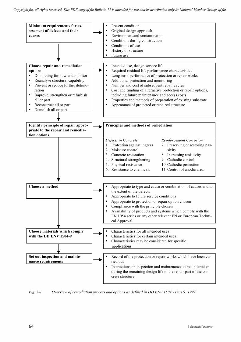
3 Remedial actions 64
Minimum requirements for as-sessment of defects and their causes
• Present condition • Original design approach • Environment and contamination • Conditions during construction
• Conditions of use • History of structure • Future use
Choose repair and remediation options • Do nothing for now and monitor • Reanalyse structural capability • Prevent or reduce further deterio-
ration • Improve, strengthen or refurbish
all or part • Reconstruct all or part • Demolish all or part
• Intended use, design service life • Required residual life performance characteristics • Long-term performance of protection or repair works • Additional protection and monitoring • Number and cost of subsequent repair cycles • Cost and funding of alternative protection or repair options,
including future maintenance and access costs • Properties and methods of preparation of existing substrate • Appearance of protected or repaired structure
Identify principle of repair appro-priate to the repair and remedia-tion options
Principles and methods of remediation
Defects in Concrete 1. Protection against ingress 2. Moisture control 3. Concrete restoration 4. Structural strengthening 5. Physical resistance 6. Resistance to chemicals
Reinforcement Corrosion 7. Preserving or restoring pas-
sivity 8. Increasing resistivity 9. Cathodic control 10. Cathodic protection 11. Control of anodic area
Choose a method • Appropriate to type and cause or combination of causes and to the extent of the defects
• Appropriate to future service conditions • Appropriate to protection or repair option chosen
• Compliance with the principle chosen • Availability of products and systems which comply with the
EN 1054 series or any other relevant EN or European Techni-cal Approval
Choose materials which comply with the DD ENV 1504-9
• Characteristics for all intended uses • Characteristics for certain intended uses • Characteristics may be considered for specific
applications Set out inspection and mainte-nance requirements
• Record of the protection or repair works which have been car-ried out
• Instructions on inspection and maintenance to be undertaken during the remaining design life to the repair part of the con-crete structure
Fig. 3-1 Overview of remediation process and options as defined in DD ENV 1504 - Part 9: 1997
Copyright fib, all rights reserved. This PDF copy of fib Bulletin 17 is intended for use and/or distribution only by National Member Groups of fib.

fib Bulletin 17: Management, maintenance and strengthening of concrete structures 65
Principle
No. Principle Examples of methods based on the principle
P
Protection against ingress Surface impregnation Surface coating Bandaging cracks Filling cracks Converting cracks to joints Erecting external panels Applying membranes
PR Increasing physical resistance Overlays or coatings Impregnation
RC Increasing resistance to chemi-cals
Overlays or coatings Impregnation
S U R F A C E
P R O T E C T I O N MC Moisture control Hydrophobic impregnation
Surface coating Overcladding
CR Concrete restoration Hand-applied mortar Recasting with concrete Sprayed concrete Replacing elements
CC Cathodic control Reducing oxygen supply at the cathode by saturation or surface coating
RP Preserving or restoring passivity Increasing cover with additional concrete or mortar Replacing contaminated or carbonated concrete Electrochemical re-alkalisation Re-alkalisation by diffusion Electrochemical chloride extraction
CP Cathodic protection Applying an appropriate electrical potential
R E P A I R
CA Control of anodic areas Applying coatings containing zinc to the reinforcement Applying barrier coatings to the reinforcement Applying inhibitors to the concrete surface which pene-trate to the reinforcement
S T R U C T U R A L
S T R E N G T H E N I N G
SS Structural strengthening Adding reinforcement by external embedment Adding reinforcement in performed or drilled holes Plate bonding Adding mortar or concrete Crack injection Filling cracks Prestressing
Table 3-2: Principles and remedial actions (after Part 9 of ENV 1504)
In general the penetration of impregnation solutions is improved the smaller the molecules of the impregnation material are. Surface coatings and membranes
Coatings can protect the surface from mechanical effects. To differentiate between a thin and a thick coating, a thin coating is defined as less than 1 mm in thickness whereas a thick coating is 1 mm or more in thickness. A thick coating is applied to smooth out any uneven-ness and small weak points on the surface.
Copyright fib, all rights reserved. This PDF copy of fib Bulletin 17 is intended for use and/or distribution only by National Member Groups of fib.

3 Remedial actions 66
Membranes provide a heavy barrier against penetrating liquids. Liquids do not easily penetrate them; - however they hinder the escape of internal moisture. The type of material and the layer thickness influence the efficiency of a sealing system. Performance of protection materials
There are a wide range of coatings and sealing products that can be applied to concrete to provide protection against chemicals, ingress of deleterious agents or moisture into concrete. For solvent-containing substances the evaporating solvent leaves fine voids which result in a certain permeability for water, internal moisture and the gas from the membranes. Solvent-free substances have, therefore, for the same layer thickness, a higher efficiency against diffu-sion. In both cases, this efficiency increases with increasing layer thickness. These are gener-ally applied over fairing or levelling coats used to provide a dense surface free from blow-holes and other minor disruptions. A filling may become necessary when the surface has too large unevenness in the form of large voids, honeycombs etc. Coatings protecting against or reducing carbonation may be applied after concrete repairs have been carried out. Such coat-ings provide enhanced resistance not only to the further carbonation of the concrete but also reduce the penetration of moisture and other substances such as chlorides.
The performance of coatings, sealers and membranes will depend not only on their formu-lation but also upon the adhesion to the substrate and freedom from pin-holes. Effective preparation of the substrate is a fundamental requirement. This may be done by grit or water-blasting to remove all loose materials and surface contaminants, fungal or organic growths.
Coatings have been significantly less successful in retarding reinforcement corrosion in concrete elements containing chlorides. These act as a catalyst and there is usually sufficient moisture and oxygen within the concrete to allow the corrosion of the reinforcement to con-tinue. It should also be remembered that chlorides form hygroscopic salts, which may attract moisture from the atmosphere into the member concerned. This can encourage the develop-ment of high water vapour pressures, potentially leading to blistering and premature failure of the coating. For some years now penetrating sealers have been applied at the time of construc-tion to the surfaces of concrete bridge substructures in both the UK and Germany.
Waterproofing membranes have been applied widely to the decks of European bridges and other structures such as car park decks. Typically, they have a 10-25 year service life. 3.4.2 Bandaging and bridging cracks
Coatings should also have the capability to bridge cracks. This requires a high elasticity of the coating material. For thinner layers bridging of cracks can only be achieved when a lim-ited de-bonding of the coating adjacent to the crack is possible. In general, with the so-called crack bridging coatings, it is possible to bridge cracks up to 0.5 mm in width. The crack bridging capacity depends on the thickness and the elasticity of the coating. Some coatings with elastomeric properties may be considered.
Bridging of larger crack widths can be achieved by the insertion of a fibre material into the coating, in the form of textile fabrics for example. Recently two-component liquid sealers have been developed which can be sprayed onto the concrete surface. They have the ability to bridge larger cracks as a result of their low modulus of elasticity and their improved elonga-tion. Some systems however are not sufficiently resistant to mechanical effects and weather-ing influences (mostly UV-rays), such that they may require an additional protection layer. They may also be used as a membrane underneath asphalt overlays.
Copyright fib, all rights reserved. This PDF copy of fib Bulletin 17 is intended for use and/or distribution only by National Member Groups of fib.
fib Bulletin 17: Management, maintenance and strengthening of concrete structures 67
3.4.3 Filling Cracks Cracks take on many and varied forms. When considering potential remedial actions it is
necessary to establish if a crack remains ‘active’ or ‘live’ and what magnitude of movements can be expected to take place across it at some future time. Otherwise the crack can be treated as being inactive and no allowance made for future movements. Crack injection can be per-formed as either a means of minimising ingress or passage of fluids or as a means of stiffen-ing / strengthening the crack member(s).
In the case of active cracks, the proposed sealing material must remain elastic. There is a variety of flexible materials which can be employed to seal these cracks. These include polyu-rethanes, polysulphides as well as some epoxy resins and polymer modified cementitious grouts. Consideration needs to be given to strain effects upon the sealing material, that is the size of the anticipated movement relative to the width of the crack (and hence the thickness of filling material involved). Cracks are usually opened out at the surface (U-shape chase) to re-duce the magnitude of the potential strain to a level with which the material can cope.
It should be recognised that the low modulus material used for sealing active cracks will not contribute significantly to the strength or stiffness of the member concerned.
Where movement has stopped pressure or vacuum techniques are generally employed to introduce low viscosity resins (various formulations) or cementitious grout into the crack(s). Low viscosity resins and micro-cements have been used to inject very fine cracks (circa 0.1 - 0.2 mm). Whilst crack injection will almost certainly strengthen / stiffen the affected mem-bers to some degree, it should be recognised that there is no effective way of checking in-situ whether the cracks have been completely filled or how well the material has bonded to the sides of the crack. It is very difficult to attempt to clean out cracks to improve bonding and the results typically remain uncertain.
The flexibility of a resin, as a rule, is not sufficient to close active cracks tightly and dura-bly in case of larger movements caused by to cyclic loading or temperature. In this case, the possibility of converting the crack into a permanent expansion joint should be explored. 3.5 Repair
As defined in paragraph 3.1, repair consists of remedial actions, which improve the func-tionality of the structure. This includes :
CR Concrete Restoration CC Cathodic Control RP Preserving or Restoring Passivity CP Cathodic Protection CA Control of Anodic areas
3.5.1 Concrete restoration 3.5.1.1 General
In all cases where concrete cover is repaired, the condition of the existing concrete in the exposed damaged area is of primary importance in the durability of the repair. The latter can be seriously compromised if there is poor adhesion between the fresh concrete of the repair and the existing sound concrete substrate. Therefore, it is important that the contact surface is in sound concrete and that all foreign materials are removed: that might affect or impair the
Copyright fib, all rights reserved. This PDF copy of fib Bulletin 17 is intended for use and/or distribution only by National Member Groups of fib.

3 Remedial actions 68
repair. In general damaged and fractured concrete must be removed to a sound surface which must be properly treated.
Various methods may be employed for undertaking patch repairs, these include hand-applied mortar, recasting with concrete and possibly sprayed concrete on large structures / members. The approach requires the removal of damaged / carbonated / contaminated con-crete in accordance with the criteria being employed and the nature of the deterioration in-volved. Depending upon the extent and severity of reinforcement corrosion, it might be nec-essary to introduce supplementary reinforcement to restore the structural strength of the ele-ments concerned.
Concrete removal might be via a range of methods including percussive tools, pneumatic hammers, hydrodemolition, water blasting, milling machines, etc. It is difficult to make com-parisons of costs for the different approaches because of the commercially sensitive nature of the information. Hydrodemolition, milling machines and the like will be the most economic approaches as the areas involved increase in size. The different techniques each have their advantages and limitations. Hydrojetting methods are probably the technique of choice on considerations of efficiency of concrete removal with minimal damage to the substrate, clean-ing of reinforcing bars and removal to a given depth. However, there can be difficulties asso-ciated with water run-off, spray, flying debris, noise, etc. 3.5.1.2 Hand-applied mortar
There are many proprietary patch repair materials on the market. These are pre-batched and generally achieve better performance and consistency than site-batched repair mixes. The proprietary materials are usually produced under a quality assurance scheme and come with certification defining their performance and characteristics. Some systems include bonding agents. These require close attention to ensure that the associated layer of repair material is applied at the correct time.
If the deterioration process has reached a level where a shallow surface repair is not feasi-ble, a replacement of the missing concrete section should be considered. The technical choice of the repair material depends on volume to be replaced, the depth of the repair, the loading effects to be expected and the conditions of application on site.
The following materials for the replacement of a substantial depth loss of the concrete sur-face should be considered: cementitious polymer modified mortar or concrete or resin sys-tems.
a) Polymer modified cement-bound system. This system is one in which a 5 % by weight or more of plastic additive (by weight of cement) is mixed with conventional concrete or mortar mixtures. This additive improves the final properties of the concrete or grout and provides high early strength. This additive is introduced into the concrete or grout mix in the form of a watery dispersion, as an emulsion or as a powder. Furthermore the compressive strength should not be significantly decreased (within 5 %) nor should the modulus of elasticity be reduced. The curing of the plastic modified cement-bound systems is of equal significance as for cement repair systems. Generally, these systems are superior to the cement-bound systems as they have increased workability and ex-hibit fewer tendencies toward shrinkage cracking especially for thin layers.
Copyright fib, all rights reserved. This PDF copy of fib Bulletin 17 is intended for use and/or distribution only by National Member Groups of fib.
fib Bulletin 17: Management, maintenance and strengthening of concrete structures 69
b) Cement mortar and concrete (possibly with additives). The use of mortar or concrete for the repair of cover damage is dependent upon the thickness required. The maxi-mum aggregate size should not exceed one-third of the required thickness.
c) Pre-formulated repair materials (specific performance characteristics). These are prod-
ucts which have been developed for specific repair conditions (surface roughness, minimum and/or maximum thickness of application etc.) and generally under specific environmental conditions (temperature range, degree of surface wetness etc.). They generally have specific instructions and procedures for application of the material to the damaged surface. These repair systems should only be used when their composi-tion is known, they correspond to the requirements of existing guidelines and their successful use under similar circumstances has been demonstrated. Under these condi-tions an increased reliability is provided to the user and the client. The use of these re-pair systems does not absolve the user from the requirements of relevant standards and guidelines as well as surface pre-treatment and proper implementation.
d) Resin systems. These are particularly beneficial when a short curing time, a high early
strength and a high resistance to chemical and physical attack are required. They are suitable for repair of surface damage, of edge damage at joints and defects in the con-crete. However, use of these systems should take into account that, compared to ce-ment-bound mortar systems, they have a larger thermal coefficient of expansion which can be up to 10 times higher than that of the concrete. Resin systems are normally only used for limited thickness. Moreover, the resin systems do not provide an alkaline en-vironment around the steel to maintain a passive layer on the rebars; they can be quite expensive. These facts make such systems less commonly used.
The various measures for damage repair may, in addition, require surface protection
measures to provide for the durability of the repair. 3.5.1.3 Sprayed concrete
Where the zones of deterioration are large it may be appropriate to utilise sprayed mortar (gunite) or sprayed concrete (shotcrete) as the repair material. This can be applied by either the dry mix or the wet mix methods, with the latter reportedly becoming more popular since proprietary mixes have been developed. Care is required to avoid the presence of voids behind the reinforcement, particularly where there are multiple layers of reinforcement.
Sprayed concrete is suitable for the repair of cover damages, concrete replacement and for the strengthening of structural elements.
Pre-treatment of the surface is of prime importance when using sprayed concrete. Sand or water-blasting has proved to be an efficient surface treatment procedure: however environ-mental protection regulations should be verified before use. No bonding agent is necessary because at the interface surface mortar enrichment occurs as a result of aggregate rebound.
Sprayed concrete is applied in layers of thickness 20 - 30 mm. Sprayed concrete in multi-ple layers requires that the preceding layer achieves a sufficient degree of hardness. Minimum reinforcement may be required for thickness larger than 50 mm. This reinforcement should be fixed in position in such manners that it remains stiff and keeps its position during shotcreting operations. Addition of fibres (steel, glass, plastics) may also be used.
Copyright fib, all rights reserved. This PDF copy of fib Bulletin 17 is intended for use and/or distribution only by National Member Groups of fib.

3 Remedial actions 70
Curing may be accomplished by an evaporation protection, e.g. plastic sheet, to prevent a rapid drying out. If a freeze-thaw/salt resistant concrete is required, a low water-cement ratio mix is used possibly with an additive added to increase tightness and compaction. Also sur-face protection measures may become necessary.
There are two basic sprayed concrete processes: a) a dry mix process where most of the mixing water is added to the nozzle and the ce-
ment sand mixture is carried by compressed air through the delivery hose to a special nozzle;
b) a wet mix process where all of the ingredients including water are mixed before enter-ing the delivery hose.
3.5.1.4 Recasting of concrete
Placing concrete in the area to be repaired should be accomplished in such a manner as not to impede concrete flow and to avoid entrapment of air. The recast concrete should have final properties that match the existing concrete as closely as possible (strength, modulus of elastic-ity).
In any structure where the repair process requires a significant proportion of the original concrete to be removed, consideration needs to be given to the residual load capacity of the member(s) concerned. Due to the different elastic modulus, thermal, shrinkage and creep characteristics of the repair material, it cannot be assumed that this will carry load in the same way as the original material. 3.5.1.5 Encasement
Encasement is used more frequently in marine environments, being used fairly often to re-pair column and beam elements in concrete jetty structures and for some bridge columns, piers and abutments. The deteriorated / contaminated concrete will be removed prior to cast-ing the encasement. This will no doubt contain reinforcement to control early age thermal and longer term moisture related shrinkage cracking.
Although the encasement may utilise traditional shuttered construction methods, it is also possible to use a sprayed concrete. 3.5.2 Preserving or restoring passivity of the reinforcement 3.5.2.1 Restoration of the protection
The decision on the necessity of removal of contaminated concrete cover, where com-mencement of the corrosion process is imminent, will depend upon the amount of contami-nant content (chloride), the availability of moisture and the degree of carbonation.
If this is the case, the corrosion protection on the reinforcing bar has to be restored. This can be achieved by encapsulating the bar in an alkaline coating : concrete (sprayed concrete), cement mortar or epoxy resin mortar. 3.5.2.2 Corrosion inhibitors
Corrosion inhibitors, which come in powder, gel and liquid form, retard the rate of the corrosion reaction. They are widely used in many industries to effectively reduce the corro-sion rate of steel and other metals. Commercial products for the control of corrosion of steel
Copyright fib, all rights reserved. This PDF copy of fib Bulletin 17 is intended for use and/or distribution only by National Member Groups of fib.

fib Bulletin 17: Management, maintenance and strengthening of concrete structures 71
reinforcement in atmospherically exposed concrete were first produced in the 1970’s. They increase the time to the onset of corrosion and then act to reduce the rate of corrosion. They can be introduced into the concrete mix at the time of construction / repair or (in a suitable formulation) applied to the surface of an existing concrete structure.
There are three main types of inhibitors: - Anodic inhibitors which retard the corrosion reaction at the anode. At low dosage there is
concern that they will suppress generalised corrosion but may fail to eliminate all anodic sites.
- Cathodic inhibitors which retard the reaction at the cathode and seek to prevent oxygen reaching the reinforcing steel. At low dosages they are effective at reducing corrosion rates but are generally less efficient than the anodic type.
- Multi-functional (ambiodic) inhibitors: these combine the benefits of both anodic and cathodic inhibitors at relatively low dosages.
Inhibitors are consumed with time and will only work up to a given level of activation (i.
e. chloride content). Calcium nitrite is one product, which has been widely used, being both added to the repair mix and applied to the surface of the concrete. Other proprietary products are available. Some work in other ways, perhaps enhancing alkalinity or blocking pores.
To be effective a corrosion inhibitor applied to the surface of the concrete has to travel to the surface of the steel. This is by diffusion and, in most instances, will be a slow process. The liquid inhibitor molecules are larger than chloride ions, so will be transported at a slower rate. Vapour phase inhibitors offer an advantage that diffusion as a vapour will be faster than as a liquid. However they may diffuse poorly through saturated concrete and may also diffuse out of the concrete. Drilling and grooving are sometimes used to speed the transport of the inhibi-tor to the steel surface. These processes are both damaging and expensive. The effectiveness of surface spraying / roller application will depend very much upon the quality of the concrete and its moisture content.
The principle of most inhibitors is to develop a very thin chemical layer on the surface of the reinforcement. There is a very wide range of corrosion protection performance from dif-ferent inhibitor formulations, even with generic classifications. Independent evaluation and certification of performance is desirable from the specifier’s point of view. However such evaluations need to be representative of field concretes and conditions. As the true effect of an inhibitor can only be evaluated from corrosion rate measurements before and after application and by reference to a control area, such systematic evaluations are lengthy processes and are in their early stages. 3.5.2.3 Re-alkalisation
This electro-chemical technique provides a means of restoring the alkalinity to carbonated but otherwise sound concrete. It involves the passage of a direct current between the rein-forcement (the cathode) and an anode applied temporarily to the surface of the concrete. This process generates hydroxyl ions at the steel surface which locally regenerates the alkalinity of the concrete raising its pH up to about 12. This helps restore the passivating surface oxide layer to the reinforcement.
Under the applied voltage, alkali ions are drawn from the anode into the concrete. The use of a sodium or potassium carbonate electrolyte is claimed to make the treatment more resis-tant to further carbonation. Several forms of anode may be employed. These are commonly either some form of mesh (titanium or steel) or electrolytic tanks (for vertical surfaces) / baths
Copyright fib, all rights reserved. This PDF copy of fib Bulletin 17 is intended for use and/or distribution only by National Member Groups of fib.

3 Remedial actions 72
(for deck slab applications). A sprayed cellulose impregnated with the electrolyte is used with the mesh anode system.
The introduction of sodium ions, when using sodium carbonate as an electrolyte, may ex-acerbate any potential the concrete has for ASR. In these cases plain water has been used as an electrolyte. It is understood that a lithium electrolyte has been proposed and tested but is still a subject of research.
The process typically takes between three and five days but sometimes may take several weeks. Successful treatment can be established by means of an acid / alkaline indicating solu-tion. However it should be noted that phenolphthalein changes colour at a pH of about 9.5 (unless a modified solution of phenolphthalein is used). This is not a passivating condition and an indicator (Universal indicator) with a colour change closer to pH 12 may be required to demonstrate that a passivating condition has been achieved.
As with cathodic protection and desalination, consideration must be given to hydrogen evolution at the reinforcement. The re-alkalisation process applies some 20 - 50 VDC be-tween the anode and the steel that must be expected to achieve steel potentials at which hy-drogen evolution could take place. It seems unlikely that re-alkalisation would need to be ap-plied to prestressed concrete structures.
Re-alkalisation requires electrical continuity of the steel in the areas to be treated, a rea-sonable level and uniformity in the conductivity of the concrete, no short circuits between the cathode and the anode and no electrically insulating layers in the cover zone / bar surrounds. The process requires fewer concrete repairs than the patch repair alternative. It is also able to treat the whole surface of the zone in question. There has been strong growth in the use of re-alkalisation in recent years (since the late 1980’s) presumably because of its greater conven-ience and cost advantage over patch repairs. 3.5.2.4 Chloride removal
Negatively charged chloride ions (Cl-) can be repelled from reinforcement and moved to-wards an external anode by making the steel cathodic and passing a direct current through the concrete. This process is known by various names such as electro-chemical chloride extrac-tion, desalination and chloride removal. It is similar in operation to cathodic protection but utilises a temporary anode and a much higher electrical power density. The cathode reaction generates hydroxyl ions that locally enhance the alkalinity of the concrete in the vicinity of the reinforcing bars and encourages their re-passivation. Treatment periods are in the order of 3 to 6 weeks. Electrolytes employed include water and saturated calcium hydroxide.
The anode types employed are essentially the same as those used for re-alkalisation pro-tection, namely either mesh systems or liquid electrolyte systems contained within tanks. A sprayed cellulose impregnated with the electrolyte is used with the mesh anode system. These use either titanium or a steel mesh (which is consumed during the treatment).
As with other electro-chemical systems, it is necessary to have electrical continuity across the zone to be treated, no electrical short circuits between anode and cathode together with a reasonable level and uniformity in the conductivity of the concrete. The approach minimises the amount of concrete repair work necessary.
It is claimed that the technique can be used to treat the whole of the concrete surface and, on the basis of life cycle costs, that it should be applicable to a wide range of structures. Care
Copyright fib, all rights reserved. This PDF copy of fib Bulletin 17 is intended for use and/or distribution only by National Member Groups of fib.
fib Bulletin 17: Management, maintenance and strengthening of concrete structures 73
needs to be exercised in relation to potential problems (as with the other electro-chemical methods, namely hydrogen evolution in the member concerned). 3.5.3 Cathodic protection
The chloride extraction and re-alkalisation repair techniques are temporary processes. Cathodic protection is a similar technique but permanent. It is now well established and is in-creasingly becoming accepted as a practical long-term solution for the rehabilitation of rein-forced concrete structures suffering from chloride induced corrosion.
The basis of cathodic protection is to eliminate corrosion by reducing the potential of the steel to a more electronegative state, thereby converting the whole of the steel reinforcement into a large cathode. This is achieved by passing a small direct current between an external anode material and the steel reinforcement material. The anode material is connected to the positive pole of a rectifier and the negative to the steel reinforcement. The production of elec-trons (cause of corrosion) which are consumed by the oxygen and water in reduction reac-tions, does not occur at the steel reinforcement. Instead the system forces electrons into the steel to be consumed in these reactions and thus protect its integrity. The production of hy-droxyl ions at the steel surface (cathodic reactions) causes the concrete to revert back to an alkaline state thus stopping the corrosion process.
Cathodic protection of reinforcing steel can be achieved by using sacrificial anodes or an external direct impressed current source. However sacrificial anodes may not be suitable in the atmospheric zones due to the high electrical resistivity of the concrete. Types of cathodic protection systems Titanium mesh anode / cementitious overlay system
This has been the system most widely used but other systems appear to have been overtak-ing it recently with regards to usage. It is applicable above ground/water level and provides even current distribution which minimises the risk of over protection. If necessary multiple layers can be used to protect large surface areas of steel. However the cementitious overlay can be susceptible to delamination if not applied correctly. It also imposes extra weight on the structure and can be susceptible to impact damage. Slotted/grid anode system
A dense titanium mesh ribbon or strip is installed in slots cut into the concrete (generally 25 mm x 25 mm) and the slots are then backfilled with a cementitious mortar compatible with the parent concrete. It has a low risk of delamination and life can be enhanced by using a larger anode strip. Minimal concrete cover can affect the uniformity of current distribution. Internal anode systems
The internal anodes are embedded in 12 mm diameter holes drilled into the concrete at depths of up to 300 to 400 mm depending upon the length of anodes required and the struc-tural component being protected. A graphite based backfill material or a conductive gel is in-jected into the holes and the 3 mm platinised titanium rods are then inserted into the anode backfill. The life of the system is basically controlled by the consumption of the graphite backfill which is estimated by the manufacturer as 20 years, although recent use of the con-ductive gel suggests a life of at least 30 years. However, experience is now showing that an-odes of this type in service seem to have difficulties in meeting the lifetime expectations of
Copyright fib, all rights reserved. This PDF copy of fib Bulletin 17 is intended for use and/or distribution only by National Member Groups of fib.

3 Remedial actions 74
the manufacturers. The system is especially cost effective on large elements such as beams, piers and columns but is not suitable for thin sections. Careful design is required to minimise cabling requirements and to ensure optimum spacing and critical positioning of anodes in the vicinity of the steel. Electroconductive tape grease/overwrap system
A conductive tape / grease system which provides a conductive path to the concrete is wrapped around a column or pile followed by titanium mesh. A further layer of conductive tape overwraps the mesh anode to secure and provide a contact surface for the outerface of the mesh anode. Mechanical protection is provided by either polyethylene or fibreglass impact resistant jackets. This system is difficult to install on large sections, is susceptible to impact loadings and appearance becomes a problem. Electroconductive tape grease/panel system
This system utilises similar technology as the overwrap system. However it is prefabri-cated fibreglass impact resistant panel which can be bolted into position. It is suitable for sof-fits, columns and beams and it is easy to install. The thickness of panels and their aesthetic appearance are its negative attributes. The expected life of the conductive gel also needs con-sideration. Water/soil anodes
These remote anodes consist of proven materials such as high silicon cast iron, lead, silver or 3-6 mm diameter platinised titanium rod embedded in cokebreeze (conductive backfill) and secured in geotextile bags in a trench. In shallow waters the anodes are dug into the mud whilst those installed in sea water are normally located flush with piers and housed in a slot-ted PVC pipe for protection from boat damage. These anodes are powered by an independ-ently controlled output from the Transformer / Rectifier and protect large areas of reinforcing steel in immersed concrete structures. These systems are mainly used in conjunction with other systems to address the problem of current dumping. Sacrificial zinc anode systems
Sacrificial zinc anodes can be either clamped onto concrete columns, immersed below the waterline or dug into the mud in order to provide protection to the buried / submerged and tidal zones. The degree of polarisation will vary as a result of several factors including the amount of current output from the anodes, the rate of polarisation obtained in the submerged / buried section, tidal variations and tidal resistivity. Overprotection of the steel reinforcement is not a concern as zinc anodes’ current output is self regulating with low driving voltage of 0.9 to 1.1 volts. Sprayed zinc CP systems
This is a very simple system with a very low initial cost outlay. It requires the application of 99.9 % pure zinc by arc-spray method at a total thickness of about 400 microns. It is a sac-rificial system, which has a life expectancy of 12 to 15 years that can be extended by whip blasting and respraying additional zinc material. It can also be installed as an impressed cur-rent system and a protective coating may be applied over it to further extend the useful life of the system. Sacrificial zinc anodes are also used in combination with these systems which protect the submerged / tidal zones and minimise current dumping.
Impressed current systems require electrical connections to distribute the impressed cur-rent across the anode, a DC power supply and an associated control system together with em-
Copyright fib, all rights reserved. This PDF copy of fib Bulletin 17 is intended for use and/or distribution only by National Member Groups of fib.

fib Bulletin 17: Management, maintenance and strengthening of concrete structures 75
bedded monitoring probes providing data by which adjustments can be made to the voltage and currents applied.
An installation will normally be divided into a number of zones, each with its own power supply. The design of the zones needs to take account of a number of factors such as the:
• variation in moisture and chloride contents (and hence the conductivity of the con-crete) across the structure,
• continuity of reinforcement in different areas, • presence of joints in the structure, • requirements for different anode types, • variation in reinforcement provision.
Commissioning is a very important stage in achieving an effective and durable CP system.
It provides the opportunity to perform a variety of tests and trials establishing the initial be-haviour of the CP system, make adjustments to current and voltage supplies and to verify con-trol criteria.
Once it has been established that an impressed current CP system is providing protection to all reinforcement, it is essential that the operation of the system be monitored and that it be properly maintained. Changes occur in the concrete over the first few months of operation (increase in resistivity due to removal of chloride ions and drying out of concrete). The objec-tive of the monitoring is to ensure that all reinforcement remains effectively protected.
For concrete structures with old types of prestressing steel, the risk of hydrogen-embrittlement shall be analysed when considered the implementation of impressed current CP systems. 3.6 Structural strengthening
Strengthening of structural members can be achieved by replacing poor quality or defec-tive material by better quality material, by attaching additional load-bearing material and by redistribution of the loading actions through imposed deformation of the structural system. The new load-bearing material will usually be high quality concrete, reinforcing steel bars, thin steel plates and straps, carbon or glass-fibre tissue or plates, post-tensioning tendons or various combinations of these materials.
The main problem in strengthening is to achieve compatibility and a continuity in the structural behaviour between the original material / structure and the new material / structure. 3.6.1 Strengthening of concrete sections
Strengthening of concrete sections may be achieved by: - Increasing the concrete section itself - Introducing new reinforcing bars in special recesses carved in the old concrete - Placing new reinforcing bars outside the old concrete and linked thanks to additional con-
crete. - Creation of a composite structure (for instance: steel-concrete composite or advanced
composite material (ACM)-concrete composite).
In each case the new section has to be designed and checked according to the design speci-fications of composite structures.
Copyright fib, all rights reserved. This PDF copy of fib Bulletin 17 is intended for use and/or distribution only by National Member Groups of fib.

3 Remedial actions 76
Satisfactory interaction between existing concrete and new concrete is required: the two parts must act as a homogeneously cast structural component. The joint between old concrete and new strengthening materials must be capable of transferring shear stresses. The joint must be durable for the environment in question.
Differences in creep and shrinkage properties between old and new structural elements will require careful evaluation. 3.6.2 Strengthening with bonded materials 3.6.2.1 Steel plates
The strengthening of concrete structures by means of bonded steel plates is a technology existing in many countries:
(a) Short-term behaviour. The load-carrying capacity of this type of strengthening depends upon the strength of the reinforcement, the concrete and the adhesive. Yielding of the reinforcement will cause the adhesive to fail. Utilisation of high-strength reinforcement is limited by the dimensions, concrete strength etc. Concrete strength has a large in-fluence on the efficiency of the strengthening because the failure plane is located within the concrete.
The concrete dimensions, according to previous tests, do not appear to have any deci-sive effect. The surface condition of the steel is an important parameter. Suitable con-ditions can be achieved by sand-blasting. Oil and grease should be removed by means of an organic solvent. As cleaned surfaces corrode rapidly, a primer coating should be applied immediately.
(b) Long-term behaviour. The question of long-term behaviour is of particular importance
for these materials, the properties of which are highly time-dependent. Of considerable importance are creep, ageing and fatigue strength
- Creep: the creep of epoxy resin adhesives is considerably greater than that of con-
crete. In accordance with the current state-of-the-art, it can be assumed that the creep deformation abates relatively quickly. In thin adhesive layers (≤ 3 mm) the influence of creep is restricted by the cohesion of the adhesive.
With increasing width, there is a risk of defects in the adhesive. Therefore the width of the reinforcing element should be limited to a maximum of 200 mm. The thickness of the adhesive coat, within a range of 0.5 - 5 mm has no significant influence on ultimate load. With increasing thickness of adhesive the slip between the reinforcing element and the concrete becomes greater.
- Ageing: ageing is a change of properties resulting from mechanical, physical and
chemical influences (e.g. air humidity, radiation, heat, weathering and water).
- Fatigue strength: preliminary tests show that the fatigue strength is approximately 50 % of the short-term strength.
- Corrosion and fire protection should be addressed.
Copyright fib, all rights reserved. This PDF copy of fib Bulletin 17 is intended for use and/or distribution only by National Member Groups of fib.

fib Bulletin 17: Management, maintenance and strengthening of concrete structures 77
3.6.2.2 Advanced composite materials
The technique of repairing structures by bonding strengthening reinforcement to the ele-ment has recently been given a tremendous boost; the explanation lies in the ability to replace traditional steel plates by flexible composites using e-glass or carbon fibres as a base. These are known as Advanced Composite Materials (ACMs).
The advantages of ACMs are numerous: - high strength and elastic moduli, - no ability to corrode, - low mass, - extreme flexibility in application to surfaces of any shape or nature, - high resistance to fatigue and wear.
Thin layers of ACMs are applied using a thixotropic resin with an epoxy base. The real
breakthrough in the scheme lies in the fact that the fixing is done cold and without pressure thanks to the development of glues and fibres specially designed for the application to Public works. In addition to the exceptional properties of the ACMs the technique offers simplicity of usage and handling.
Caution must be exercised in using ACMs, especially in the case of shear enhancement, where strain compatibility between the ACM and the base material must be achieved, with a maximum limiting strain of 0.004. In flexure, ACMs must have sufficient bonding area to ensure the tear strength of the base material (concrete) is not exceeded. It should also be rec-ognised that by increasing the flexural capacity of a member, the shear demand is also in-creased and this must be allowed for in the design. Fire protection issues should be addressed (see Appendix 8 for retrofitting examples). 3.6.3 Strengthening with additional prestressing
General: in many cases strengthening by means of post-tensioning is a highly effective method. Both reinforced concrete and prestressed concrete structures can be strengthened by means of post-tensioning. The influence of post-tensioning on serviceability and ultimate limit states can be varied within wide limits by selecting different methods of introducing the tensioning force and using different alignments for the tendon. Both bonded and unbonded tendons can be used.
Special design considerations: strengthening by means of post-tensioning can normally be designed in the same way as an ordinary prestressed member. When calculating prestress losses, however, it should be noted that the effects of creep and shrinkage may generally be less than in normal design due to the age of the old concrete. The stress in an unbonded ten-don in the ultimate state will be only slightly larger than that after prestress losses.
Protection against corrosion and fire: the post-tensioning tendons should be protected against corrosion and fire to the same extent as in a newly-built structure. The requirements for concrete cover are the same as for ordinary prestressed concrete structures.
Anchorage and deviators: as the post-tensioned tendons are not embedded in the structure in the conventional manner, special attention must be given as to how the force is introduced.
Copyright fib, all rights reserved. This PDF copy of fib Bulletin 17 is intended for use and/or distribution only by National Member Groups of fib.

3 Remedial actions 78
There are several methods available for the attachment of supplementary prestressing: - anchorage at girder ends (abutment), - additional supports either in concrete or steel fixed to the web of the box girder, - anchorage at existing diaphragms, - deviators: these devices can be either concrete or steel. They are attached to the existing
webs or flanges by short prestressing bars. 3.6.4 Miscellaneous Strengthening by precast elements
Strengthening could also be achieved by adding precast elements. It requires bond be-tween the two structural elements at their interface. A resin-modified cement bond mortar layer is used. Strengthening by imposed deformation
By means of imposed deformation, over-stressed sections of a structure can be partially re-lieved. With this the load-carrying capacity of the whole structure is improved. A self-equilibrated stress condition can be induced in the structure by relative displacement (raising and/or lowering) of the supports or by the introduction of new intermediate supports.
It is important to note that relieving some sections of the structure will increase action ef-fects (bending moment and shear) in other sections. Another important factor is time - relative settlement of the supports, shrinkage and creep of the old structure and the new supporting elements will influence the distribution of the action/effects in the structure.
Modification of the structural system: sometimes it is worthwhile to revise the mechanical behaviour of the structure. 3.7 Demolition
As per chapter 3.3, sometimes investigations and evaluation result in the decision to de-molish and reconstruct. So, the constant improvement of the properties of materials and the increasingly strict respect for the requirements of the quality of life and of the environment are greatly contributing to the growing difficulties encountered when concrete structures are being modified or dismantled. Demolition calls for an understanding and responsible ap-proach and is supported by technological developments in drilling, cutting, sawing and explo-sives. 3.7.1 Design and procedures
Work has to be carefully planned. It requires sometimes very specific analyses including all per different steps used for construction :
• Check per stability of per remaining structure at each stage. • Carry out structural calculation. • Define it most adapted technology and equipment. • Develop safety procedures.
A demolition, a dismantling project is rather then a de-construction project.
3.7.2 Demolitions technologies
The various available technologies have been developed around three main ideas:
Copyright fib, all rights reserved. This PDF copy of fib Bulletin 17 is intended for use and/or distribution only by National Member Groups of fib.

fib Bulletin 17: Management, maintenance and strengthening of concrete structures 79
Mechanical effect: these technologies use dynamic action of pneumatic hammer or the
high pressure of hydraulic wedges or the sharp cutting of a very high pressure water jet per diamond sawing.
Blasting and explosives: this is an economical technology, fast and efficient, however there are significant disadvantages affecting environment: concrete debris projections, soil vibration, noise and possible surroundings damages.
Thermal cutting: several technologies have been used based on this principle. The most commode is the oxy-cutting with a long lance (3 to 4 m). It is fast and silent. It does not re-quire heavy equipment. The safety procedures need to be well established and satisfied (smoke emission, high temperature debris). 3.7.3 Re-cycling of materials
In order to minimise the overall cost of the operation and to salve the difficult problem of transport and evacuation of concrete remains, successful attempt has been made to re-cycle these materials (foundations base of motorway). 3.7.4 Selection criteria
Various criteria need to be taken into account ; these are likely to include the following : • Cost analysis • Speed of the demolition work • Effect on the environment • Accuracy of the work • Effective control during demolition work.
Copyright fib, all rights reserved. This PDF copy of fib Bulletin 17 is intended for use and/or distribution only by National Member Groups of fib.
fib Bulletin 17: Management, maintenance and strengthening of concrete structures 81
4 Reporting 4.1 Types and purpose of report
The nature and format of the report will obviously depend upon the investigations and as-sessments that have been undertaken and are to be described. The purpose of the report is to provide a record of what has been done and to communicate to the client in a succinct manner the outcome of this activity. Typically the report will summarise the work that has been un-dertaken, describe the outcome of the evaluations made, detail the conclusions drawn and set down the recommendations that are being made.
Earlier in this document the types of inspection / assessment undertaken were broadly categorised as:
• ad hoc inspections, • routine inspections as part of a management and maintenance system (MMS), • special inspections and assessments, often undertaken as part of a MMS.
Whilst the purpose of the particular inspection / assessment reports might be quite differ-
ent, typically their objective will be to describe : • general investigations undertaken, which may be supplemented by basic testing, • detailed investigations and assessments, which may involve specialist testing and in-
vestigation procedures, • re-calculation and evaluations made, • possible remedial options. In addition reports may be required which consider a wider perspective, such as the poten-
tial strategy options for a population of (similar) structures, such as groups of bridges.
It is also important to recognise the influence that different approaches to the phasing and definition of the scope of an investigation / testing / evaluation of condition, or the considera-tion to be given to remedial options, might have upon the reporting requirements. For exam-ple, it may suit a particular client or situation for the assessment to be undertaken as a number of phases with a report being produced at the end of each phase. Such an approach might re-quire a preliminary report after a desk study of available documents and an initial site inspec-tion. Another report might then be produced after detailed inspection and testing had been completed, with perhaps another to describe the results of any re-calculation and evaluations made. Such an approach would require a final report setting down the conclusions drawn, the options for remedial actions and the recommendation(s) being made. Conversely the brief for the assessment could require that all these issues be addressed in a single package of work.
Accordingly a standard report format is difficult to define because of the wide range of re-quirements and circumstances that may arise. It is however possible to provide an indication of the topics that might be covered and to make some general observations in respect of these. The process of critically reviewing and marshalling information for the preparation of a report should be used as a basis of testing that the investigation and assessment process has posed and addressed an appropriate series of questions. 4.2 General requirements for a report
The following quotation from Rudyard Kipling’s poem ‘I keep six honest serving-men’ enunciates the key questions which need to be answered to ensure that a technical report con-tains adequate information:
Copyright fib, all rights reserved. This PDF copy of fib Bulletin 17 is intended for use and/or distribution only by National Member Groups of fib.

4 Reporting 82
I keep six honest serving-men (They taught me all I know)
Their names are What and Why and When And How and Where and Who.
Any author who seeks to answer these questions will generally be assured of presenting
the essential factual information upon which subsequent interpretations and deductions can be based. Unfortunately all too commonly this is not achieved, leading to a lack of precision and uncertainty about what has been done and the conclusions which should be drawn.
There are a number of general questions that may need to be considered when defining the scope and objectives of a report. These include:
• Which topics need to be covered in the report? • Who are the proposed audience and does this introduce any special requirements? • How long should the report be?
A report must be objective and balanced. Great care is required in the use of language to
produce a readable document. The prospective audience may limit the use of technical terms and it will often be necessary for these to be explained in simple language to ensure that their meaning is clear. Clarity is often achieved by marrying precision of expression with a logical flow of information. There needs to be adequate cross-referencing to related issues to ensure that any inter-relationships are clearly and comprehensively explained. The appropriate use of illustrations and visual aids will generally greatly improve the clarity of a report.
It is generally considered essential to separate factual information from deductions, inter-pretations and opinion. It will usually be desirable to explain what consideration has been given to client imposed constraints and to non-engineering factors influencing the evaluation of remedial and future use options. Comment or advice should be strictly limited to the field(s) of expertise of the author(s).
If the client requires an oral report in advance of the submission of the written report, it is essential that the contents of any oral report be confirmed in writing as soon as possible. 4.3 Report structure and content
The following provides comment upon most of the possible components of a report. An individual report may incorporate only some of these, depending upon its particular scope and objectives.
Title page: This might typically contain the following information : • name of structure(s) and where they were located, • purpose of investigation or appraisal, • for whom the investigation or appraisal was undertaken (i. e. client), • who undertook the investigation or appraisal (i. e. author(s) and their organisation), • any relevant project or structure reference numbers, • status and date of report.
Synopsis / Executive summary: A page or two providing a concise overview of the as-sessment works carried out (so far). The precise scope will depend upon the brief for the work but might include a summary of the investigations and testing undertaken, the findings thereof, the re-calculation and evaluations made, the remedial options considered, together
Copyright fib, all rights reserved. This PDF copy of fib Bulletin 17 is intended for use and/or distribution only by National Member Groups of fib.

fib Bulletin 17: Management, maintenance and strengthening of concrete structures 83
with the conclusions drawn and the recommendations made. The synopsis should be written in plain language such that, in general, a layperson could understand it. The synopsis should not contain anything that has not been presented in the body of the main report.
List of contents: This is essential for larger reports and allows selective reading. Introduction / background: This would typically contain a description of the structure(s)
concerned, together with any ancillary information relevant to the purpose of the assessment carried out. This ancillary information might give details of the past use and loadings applied to the structure, significant alterations to the structure, a description of previous investiga-tions, problems and any remedial works undertaken. Any limitations imposed on cost or other factor (e. g. access) or the time available for the assessment that had affected the outcome of the work would probably be reported in this section.
Terms of reference (Brief): This should set out the scope of the work agreed between the client and the organisation undertaking the investigation or appraisal. The relevant parts may be quoted or copies of the original proposal, together with any subsequent variations thereto, reproduced within an appendix to the report. In effective the report should provide a response to the issues set down in the brief.
Documents examined / sources of information employed: It is useful to detail the docu-ments made available to the engineer plus other sources of information employed in the inves-tigation or appraisal.
Inspections undertaken and testing carried out: Comprehensive details of all investiga-tions, inspections and testing undertaken should be presented. In the case of inspections and investigations, a concise description should be given of the findings made at each location and any limitations on the effectiveness of these procedures noted. The nature, number and loca-tion of samples taken for laboratory testing should be noted. Similar details should also be provided for any in-situ tests carried out. It is usual to record the names of any client or other representatives witnessing investigations, inspections and testing undertaken. Details should be given of the laboratory tests undertaken to establish the mechanical, chemical and other characteristics of materials. It is often required that such tests are performed by a reputable independent laboratory that is accredited by a third party. Details of these arrangements should be provided. Typically only a resume of the findings will be included in the text of the main report, with copies of the laboratory test results and other supporting information being provided in an appendix to the report.
Correlation of NDT and inspection data / interpretation of results: This is a crucial activ-ity that explains the significance of the results of the investigations, inspections and testing undertaken. The basis of interpretation should be set down, with reference being made to standards, codes of practice or guidance documents as appropriate.
Calculations undertaken: The main text of the report will often present a resume of the analyses or calculations performed, describing the process which has been followed, the as-sumptions and deductions made and the criteria against which the outcome has been judged. Copies of the calculations will generally be presented in an appendix.
Discussion of evidence: This section of the report discusses the findings and seeks to es-tablish their relative importance particularly in relation to issues raised in the brief for the work. The most significant findings should be given the greatest prominence. It is important to confirm the criteria that the investigations, test results and evaluations have been inter-preted against.
Consideration of remedial options / evaluation of future service life: Generally this section would be expected to provide a discussion and overview of the various options and their rela-tive merits, with more detailed analysis being contained in an appendix.
Copyright fib, all rights reserved. This PDF copy of fib Bulletin 17 is intended for use and/or distribution only by National Member Groups of fib.
4 Reporting 84
Conclusions: These should be clear and based upon evidence gathered and reviewed in the preceding sections of the main text. If the document has been well written the reader should have arrived at the conclusions unaided. It is especially important that plain language is used which can be understood by a layperson that may receive the report.
Recommendations: These should be clearly stated in plain language, relate to the conclu-sions and the constraints imposed by circumstances or the client. The recommendations will often describe only the broad principles of the proposed action, with more detail being given elsewhere in the report or in a technical appendix.
Figures and plates: As required, it is helpful to incorporate a list of figures and plates (photographs) presented in the report. It may be preferred to incorporate the figures and plates within the main body of the text.
Tables: As required, it is helpful to incorporate a list of tables presented in the report. It may be preferred to incorporate the tables within the main body of the text.
References and acknowledgements: As required, limit references to those documents which might reasonably be obtained and understood by the intended reader.
Technical annexes / appendices for supporting information: As required. It may be appro-priate for them to be contained in a separate volume to the text of the main report. 4.4 Process of preparing a report
The preparation of a technical report requires not only planning, to ensure that all the in-puts required will be available from the relevant people at the appropriate time, but also con-sideration of the requirements of the audience who are expected read the report. It is generally recognised that it is advisable to keep sentences short; the Fog Index [154] provides a measure of the readability of a document.
On a purely mechanistic level, consideration must be given to the time-scales required and a programme for report preparation developed. Thought must be given to the sequence in which the report will be drafted – typically the introduction is written after the text of the main body of the report is completed and the synopsis / executive summary will be prepared last of all.
Have any special format or other requirements been specified in the client’s brief? For ex-ample, is an electronic version of report and / or supporting data required by client for archiv-ing purposes? If so, has a particular software package been specified and which version
The preparation of a report is generally an iterative process, involving drafting and selec-tive re-drafting of the report. An internal critical review of the report is essential prior to its release to the client. What procedures are to be adopted for the checking, authorising and issu-ing the report? Will it be necessary to issue a draft report to the client for comment?
Consideration should be given to presenting the report to the client. This can be particu-larly valuable in the case of large and complex assessments and where the client’s input is re-quired to aid the evaluation of alternative remedial options.
Copyright fib, all rights reserved. This PDF copy of fib Bulletin 17 is intended for use and/or distribution only by National Member Groups of fib.

fib Bulletin 17: Management, maintenance and strengthening of concrete structures 85
5 Forward look 5.1 Socio-economic drivers for change
There is a need to extend the useful service life of concrete infrastructure whilst seeking to reduce the residual life costs and environmental impact of achieving this, yet still meet speci-fied safety criteria. This need is driven by the ever-increasing burden of maintaining such as-sets, particularly as many concrete structures exposed to aggressive environmental conditions (chlorides) are falling to be as durable as expected at the time of design.
Based on current approaches to structure assessment, the level of expenditure required for the maintenance is expected to grow substantially in the next few years as existing concrete structures age and deteriorate. It is unlikely that the financial resources required will be avail-able to meet these needs.
There are also environmental pressures to increase the life of existing structures, such as the desire to minimise waste and preserve the energy (and associated pollution) embodied within the fabric of existing structures. Better-targeted remediation actions should reduce the use of resources and the impact of the environment. It should also improve the quality of life, health and safety of citizens by reducing the intrusion of noise, disruption, traffic delays dust etc … arising from repair and rehabilitation works. The public must be expected to become more demanding and less tolerant of disruption and interruption of their lives and business activities.
These issues will need to be addressed under a number of headings such as the following: 5.2 Management and maintenance issues
• Whole-life costing model • Customer focus • Internet / Web based structure management systems • New funding and associated procedures for management of existing infrastructure and
assets – Private-Public Partnerships & Finance Rehabilitate and Operate Models etc … • Human resource development and application – training to meet new skill needs • Reduction in the use of natural resources and the impact upon the environment • The implementation of Total Quality Management Systems • Interactive management and control of the risk and loading environment of infrastruc-
ture and assets such as minimising the risk of excessive vehicular loading on a bridge. 5.3 Assessment methodologies
• Improvements in-service performance modelling and prediction methods (structural performance, durability representation, probabilistic and deterministic methods etc ...), supported by enhanced in-service monitoring and information handling methods
• Developments in NDT and inspection techniques and hardware, including robotic pro-cedures and use of information technology to support decision making and evaluation of data.
Copyright fib, all rights reserved. This PDF copy of fib Bulletin 17 is intended for use and/or distribution only by National Member Groups of fib.

5 Forward look 86
5.4 Remedial actions • Demand to meet aesthetic requirements rather than only performance needs • New materials and processes for remediation • Impact of standardisation and economic factors such as the European Construction
Products Directive, on the market for new products and processes for remediation. 5.5 Coordination and standardisation
• Cooperation and coordination between different types of Owners and Users, nationally and internationally
• Overall framework for setting up Management and Maintenance Systems (MMS) • ISO Standards etc….
Copyright fib, all rights reserved. This PDF copy of fib Bulletin 17 is intended for use and/or distribution only by National Member Groups of fib.
fib Bulletin 17: Management, maintenance and strengthening of concrete structures 87
Bibliography [1] Austroads Concrete Durability Project, McGEE - Deputy Secretary Transport
Infrastructures (Australia), 1996 [2] Inspection and Maintenance of Reinforced and Prestressed Concrete Structures,
FIP Guide to Good Practice [3] Strategies for Testing, Assessment and Repair of Concrete Structures subject to
Reinforcement Corrosion, CEB Working Party V/4.1 (2nd draft) - Dr. R.M. MOSS (U.K.)
[4] Durability assessment for the reinforcement, CEB Working Party V/4.1 (2nd draft) - Michael RAUPACH (Germany)
[5] Non-destructive techniques for corrosion evaluation of steel in concrete, DEVALAPURA - M.R. KAMEL - P. ARUMUGASAAMY (USA)
[6] Appraisal of bridge structures, CEB Working Party V/4.1 - Jas ZNIDARIC (Slo-venia)
[7] Assessing corrosion damage on reinforced concrete structures, Dr. John P. BROOMFIELD (U.K.)
[8] Analysis and evaluation of bridge behaviour under static load testing leading to better design and judgement criteria, HASSAN - O. BURDET - R. FAVRE (EPFL) - (Switzerland)
[9] Post-tensioning level criterion for bridge design and rehabilitation, HASSAN - H. CHARIF - R. FAVRE (EPFL) - (Switzerland)
[10] Repair and maintenance of reinforced concrete, CURRIE and P.C. ROBERY (BRE) - (U.K.)
[11] Mesure de contraintes sur ouvrages d’art par une méthode de libération minia-turisée, ABDUNUR (LCPC) - (France)
[12] Methodology for the assessment of the structural behaviour of concrete bridges, HENRIQUES - F.J.L.C. CALHEIROS - J.A. FIGUEIRAS (PORTO University) - (Portugal)
[13] Optimisation of maintenance of concrete structures through service life calcula-tion, HENRIKSEN (Denmark)
[14] Evolution of bridge maintenance management systems, VASSIE (U.K.) [15] Risk-based approaches to economic appraisal, load assessment and management
of bridges : a review, RUBAKANTHA - P.R. VASSIE - G.A.R. PARKE (U.K.) [16] Bridge management systems : the need to retain flexibility and engineering
judgement, DARBY - P. BROWN - P.R. VASSIE (U.K.) [17] A practicable assessment system of the condition of bridges, STRANINGER - M.
WICKE (Austria) [18] Concrete bridges management using knowledge-based systems, de BRITO - F.
BRANCO (Lisbon - Portugal) [19] Economic optimization in the Danish bridge management system, LAURIDSEN -
A. KNUDSEN (Denmark) [20] Inspection of Structures, (in Danish), Danish Road Directorate, November1994 [21] Inspection and maintenance of reinforced and prestressed concrete structures, FIP
Good Practice Guide, 1983. [22] The testing of concrete in structures, BUNGEY J H, Surrey University Press, UK, 1989.
Copyright fib, all rights reserved. This PDF copy of fib Bulletin 17 is intended for use and/or distribution only by National Member Groups of fib.

Bibliography 88
[23] Diagnosis and assessment of concrete structures - State of the art report, CEB Bulletin No 192, 1989.
[24] Testing concrete in structures - A guide to equipment for testing concrete in structures, BUNGEY J H, CIRIA Technical Note 143, London, 1992.
[25] Appraisal of existing structures, The Institution of Structural Engineers, London, 1996. [26] Conservation des structures en béton, SIA 162/5, Société suisse des ingénieurs et des
architects, Zurich, 1997. [27] Subsurface radar as an investigative technique, MATTHEWS S.L., Building Research
Establishment Report, CRC, Garston, Watford, UK, 1998. [28] Electrochemical methods for monitoring corrosion of steel in concrete, Hollinshead K,
Building Research Establishment Information Paper IP97/xxx, CRC, Garston, Watford, UK, 1998 (to be published).
[29] Diagnosis and assessment of concrete structures - State of the art report, CEB Bulletin d’Information No 192, Lausanne, January 1989.
[30] Load testing of beam and block floors - Structures and Buildings, Moss R.M., Proceed-ings of The Institution of Civil Engineers, London, May 1993, Vol. 99, p.211-223.
[31] Guide to assessment of concrete strength in existing structures, BS 6089 : 1981: BSI, London.
[32] Concrete core testing for strength, Technical Report TR11, Concrete Society, London, 1987.
[33] Permeability testing of site concrete - A review of methods and experience, Technical Report TR31, Concrete Society, London, 1988.
[34] Analysis of hardened concrete, Technical Report TR32, Concrete Society, London, 1989.
[35] Half-cell potentials of uncoated reinforcing steel in concrete, ASTM: C876 [36] The half-cell potential method of locating corroding reinforcement in concrete struc-
tures, TRL Application Guide 9 [37] Report from RILEM TC-154 (in preparation). [38] Methods of Structural Reliability Analysis, Joint Committee on Structural Safety [39] Guidelines for Loading and Safety Regulations, NKB Report 55, Nordic Committee for
Building [40] Design of Highway Bridges - Supplement No. 1 - Existing Bridge Evaluation, CSA S6-
1990, Canadian Standard Association, Rexdale, Ontario Canada, 1990 [41] Guide Specifications for Strength Evaluation of Existing Steel and Concrete Bridges,
AASHTO 1989 [42] Structural Reliability Methods, Ditlevsen O. & Madsen H. O., Wiley Interscience-
Europe, 1995 [43] Methods of Structural Safety, Madsen H.O., Krenk S. & Lind N.C, Prentice-Hall, 1986. [44] Structural Reliability Theory and Its Applications, Thoft-Christensen P. & Baker M.B.,
Springer Verlag, 1982. [45] Safety, Reliability and Risk Concepts, Sørensen J. D., Institute of Building Technology
and Structural Engineering, University of Aalborg, Denmark [46] Structural Reliability - Analysis and Prediction, Melchers, R.E., Ellis Horwood Limited
1987. [47] Recommendations for Loading and Safety Regulations for Structural Design, NKB Re-
port 36, Nordic Committee for Building, 1978.
Copyright fib, all rights reserved. This PDF copy of fib Bulletin 17 is intended for use and/or distribution only by National Member Groups of fib.

fib Bulletin 17: Management, maintenance and strengthening of concrete structures 89
[48] Reliability Evaluation of Bridges to Reduce Strengthening and Repair Costs, Enevold-sen I. & Arnbjerg-Nielsen T., International Seminar on Bridge Engineering and Man-agement in Asian Countries, Jakarta, Indonesia 1996.
[49] Limit Analysis and Concrete Plasticity, Nielsen M. P., Prentice-Hall Inc., Englewood Cliffs, New Jersey 1984.
[50] Rules for Load Capacity Evaluation of Existing Bridges, Danish Road Directorate, April 1996 (In Danish)
[51] Maintenance et réparation des ponts, Edit. Calgaro Jean-Armand and Lacroix Roger. Presses des Ponts et Chaussées, Paris 1997.
[52] Assessment Procedure and Safety Evaluation of Concrete Bridges, Bergmeister K., CEB Bulletin No. 239, 1997
[53] Condition Rating Methods for Concrete Structures, Znidaric J. & Perus I., Slovenian National Building and Civil Engineering Institute, Ljubljana, Slovenia
[54] Creating a Bridge Management System, Lauridsen J., Bjerrum J., Andersen N.H. & Lassen B., Structural Engineering International 3/98
[55] ACI Report 228.2R-98 / Nondestructive Test Methods for Evaluation of Concrete in Structures – ACI Committee 228, ACI International, Farmington Hills, Michigan, USA
[56] ACI Report 201.1R / Guide for Making a Condition Survey of Concrete in Service - ACI Committee 228, ACI International, Farmington Hills, Michigan, USA
[57] ACI Report 207.3R / Practices for Evaluation of Concrete in Existing Massive Struc-tures for Service Conditions - ACI Committee 228, ACI International, Farmington Hills, Michigan, USA
[58] ACI Report 222R / Corrosion of Metals in Concrete - ACI Committee 228, ACI Interna-tional, Farmington Hills, Michigan, USA
[59] ACI Report 224.1R / Causes, Evaluation and Repair of Cracks in Concrete Structures - ACI Committee 228, ACI International, Farmington Hills, Michigan, USA
[60] ACI Report 228.1R / In-Place Methods to Estimate Concrete Strength - ACI Committee 228, ACI International, Farmington Hills, Michigan, USA
[61] ACI Report 437R / Strength Evaluation of Existing Concrete Buildings - ACI Commit-tee 228, ACI International, Farmington Hills, Michigan, USA
[62] ASTM Standard C 597 / Test Method for Pulse Velocity Through Concrete - ACI Com-mittee 228, ACI International, Farmington Hills, Michigan, USA
[63] ASTM Standard C 823 / Practice for Examination and Sampling of Hardened Concrete in Constructions - ACI Committee 228, ACI International, Farmington Hills, Michigan, USA
[64] ASTM Standard C 856 / Practice for Petrographic Examination of Hardened Concrete - ACI Committee 228, ACI International, Farmington Hills, Michigan, USA
[65] ASTM Standard C 876 / Test Method for Half-Cell Potentials of Uncoated Reinforcing Steel in Concrete - ACI Committee 228, ACI International, Farmington Hills, Michigan, USA
[66] ASTM Standard C 1152 / Test Method for Acid-Soluble Chloride in Mortar and Con-crete - ACI Committee 228, ACI International, Farmington Hills, Michigan, USA
[67] ASTM Standard C 1218 / Test Method for Water-Soluble Chloride in Mortar and Con-crete - ACI Committee 228, ACI International, Farmington Hills, Michigan, USA
[68] ASTM Standard D 4580 / Practice for Measuring Delaminations in Concrete Bridge Decks by Sounding - ACI Committee 228, ACI International, Farmington Hills, Michi-gan, USA
Copyright fib, all rights reserved. This PDF copy of fib Bulletin 17 is intended for use and/or distribution only by National Member Groups of fib.

Bibliography 90
[69] ASTM Standard D 4788 / Test Method for Deflecting Delaminations in bridge Decks Using Infrared Thermography - ACI Committee 228, ACI International, Farmington Hills, Michigan, USA
[70] ASTM Standard G 15 / Terminology Relating to Corrosion and Corrosion Testing - ACI Committee 228, ACI International, Farmington Hills, Michigan, USA
[71] British Standard BS 1881 Part 204 / Recommendations on the Use of Electromagnetic Covermeters - ACI Committee 228, ACI International, Farmington Hills, Michigan, USA
[72] British Standard BS 1881 Part 205 / Recommendations for Radiography of Concrete - ACI Committee 228, ACI International, Farmington Hills, Michigan, USA
[73] British Standard BS 1881 Part 207 / Recommendations for the Assessment of Concrete Strength by Near-to-surface Tests - ACI Committee 228, ACI International, Farmington Hills, Michigan, USA
[74] British Standard BS 1881 Part 5 / Methods for Testing Concrete for Other Than Strength - ACI Committee 228, ACI International, Farmington Hills, Michigan, USA
[75] Testing and Monitoring the Durability of Concrete Structures : Technical Guide no. 2 – Concrete Bridge Development Group – Ed. Concrete Society
[76] Corrosion of Steel in Concrete – BRE Digest 444 Part 1-2-3 [78] Durable concrete structures - CEB design guide : 2nd edition, CEB Bulletin 182, June
1989, Comité Euro-International du Béton, Lausanne, Switzerland, 1989 [79] CEB / FIP model code 1990 – Design Code, CEB Bulletins 213 - 215, May 1993,
Comité Euro-International du Béton, Lausanne, Switzerland, 1993 [80] Minimum requirements for durable concrete, Editor D W Hobbs, British Cement Asso-
ciation, 1998 [81] New approach to durability design - An example for carbonation induced corrosion,
CEB Bulletin 238, May 1997, Final report of Comité Euro-International du Béton (CEB) Task Groups 5.1 on Material behaviour exposed to environment and 5.2 on En-vironmental actions, Lausanne, Switzerland, 1997
[82] Design of durability of concrete, Proceedings of joint DuraNet & CEN/TC 104 Work-shop, Berlin, 15 & 16 June 1999, CEN/TC 104 "Concrete", CEN TC/104 N270.
[83] Structural concrete - Behaviour, design and performance: Updated knowledge of the CEB / FIP model code 1990, fib Bulletin 3, Fédération Internationale du Béton, Lausanne, Switzerland, 1999
[84] General principles on reliability for structures, ISO 2394, International Standards Or-ganisation, 1986
[85] Introduction to safety and reliability of structures, J Schneider, Structural engineering document 5, International Association for Bridge and Structural Engineering, IABSE, 1997
[86] Structural Eurocodes EN 1990 – EN1999 series, including: EN 1990: Basis of Design EN 1991: Eurocode 1: Actions on structures EN 1992: Eurocode 2: Design of concrete structures.
[87] Structural Eurocodes – their adoption in the UK, H Gulvanessian, BRE Information Paper IP3/99, CRC Ltd, London, 1999
[88] Design Manual for Roads and Bridges, Highways Agency, HMSO, London, UK - a se-ries of guidance documents concerned with concrete and other types of bridge struc-tures, including :
Copyright fib, all rights reserved. This PDF copy of fib Bulletin 17 is intended for use and/or distribution only by National Member Groups of fib.
fib Bulletin 17: Management, maintenance and strengthening of concrete structures 91
Volume 3 – “Highway structures: Inspection and maintenance” Section 1: Inspection Part 4 BD 63/94 Inspection of highway structures Part 5 BA 63/94 Inspection of highway structures Section 3: Repair Part 2 BA 35/90 The inspection and repair of concrete highway structures Section 4: Assessment Part 3 BD 21/97 The assessment of highway bridges and structures Part 18 BA 44/96 The assessment of concrete highway bridges and structures
[89] MI 15011-1988 : Technical Directives - Static test for load-capacity of existing build-ings, Hungarian Standards Body, Budapest, Hungary, 1988
[90] DIN 1076 (1994): Richtlinie zur einheitlichen Erfassung, Bewertung, Aufzeichnung und Auswertung von Ergebnissen des Bauwerksprüfungen, Bundesministerium für Verkehr, Abteilung Straßenbau (NB: Guideline for unified registration, assessment, recording and analysis of results from testing of structures), Federal Ministry for Traffic, Depart-ment for Road Construction
[91] L'Instruction Technique pour la Surveillance et L'Entretien des Ouvrages d'Art, 19 Oc-tober 1979
[92] Appraisal of existing structures, Institution of Structural Engineers, London, 1980 [93] Appraisal of existing structures - 2nd edition, Institution of Structural Engineers, Lon-
don, 1996 [94] Diagnosis and assessment of concrete structures : State of the art report, CEB Bulletin
192, January 1989, Comité Euro-International du Béton (CEB), Lausanne, Switzerland, 1989
[95] Strategies for testing and assessment of concrete structures, CEB Bulletin 243, May 1998, Final report of Comité Euro-International du Béton (CEB) Working Party V4.1 on “Testing and assessment techniques”, Lausanne, Switzerland, 1998
[96] Management of concrete structures for long-term serviceability, Editors E A Bryars & T McNulty, Proceedings of the International Seminar held at the University of Shef-field, UK on 13 November 1997,Thomas Telford, London, 1997.
[97] Considerations for use in managing the aging of nuclear power plant concrete struc-tures, Editor D J Naus, RILEM Technical Report No 19, State of the art report of RILEM Technical Committee 160-MLN "Methodology for life prediction of concrete structures in nuclear power plants", RILEM, Cachan, France, 1999.
[98] Protective systems against hazards - Nature and extent of the problem, fib Bulletin 5, Fédération Internationale du Béton, Lausanne, Switzerland, 1999
[99] Application of subsurface radar as an investigative technique, S L Matthews, BRE Re-port BR 340, CRC Ltd, London, 1998
[100] Development priorities for non-destructive examination of concrete structures in nu-clear plant, Nuclear Energy Agency, Committee on the safety of nuclear installations, NEA/CSNI/R(98)6, October 1998.
[101] Combined NDT for system assurance in railway construction : Impact-Echo, Ultrasonic and Radar techniques, C. Colla, B. Milman, J. Wostmann, F. Mielentz, J. Henschen and H. Wiggenhauser – Bauwerkdiagnose – Praktische Anwendungen Zerstorungsfreier Prüfungen, München, 21-22 January 1999
[102] Reliability assessment of pile-supported structural systems, M R Chowdhury, D Wang & A Haldar, ASCE Journal of Structural Engineering, January 1998, p80 - 88.
Copyright fib, all rights reserved. This PDF copy of fib Bulletin 17 is intended for use and/or distribution only by National Member Groups of fib.

Bibliography 92
[103] Guidance on the selection of measures for enhancing reinforced concrete durability, Editor P Bamforth, Report for DETR Partners in Technology Project CI 39/3/376, Con-crete Society, Crowthorne, UK (in press).
[104] Draft recommendation for repair strategies for concrete structures damaged by rein-forcement corrosion, Materials and Structures, 1994, Vol 27,No 171, p415-436. RILEM Technical Committee 124-SRC,
[105] European Code of Practice EN 1504 series: Products and systems for the protection and repair of concrete structures.
[106] Risks and structural safety, J B Menzies, Hazards, The Structural Engineer, Vol 73, No 21, 7 November 1995, p357-363.
[107] Current structural safety topics in North America, K L Carper, The Structural Engineer, Vol 76, No 12, 16 June 1998, p233-239.
[108] SCOSS: Structural safety1997-99: Review and recommendations, 12th Report of the Standing Committee on Structural Safety, SETO Ltd, London, 1999
[109] Assessment of large panel system built dwellings for accidental loading, B Reeves, T D G Canisius & S L Matthews, International Congress "Creating with Concrete", Sept 1999, Dundee, UK.
[110] Life-cycle cost analysis for protection and rehabilitation of concrete bridges relative to reinforcement corrosion, R L Purvis, K C Clear & M J Markow, Strategic Highways Research Programme Report SHRP-S-377, National Research Council, Washington DC, USA, 1994.
[111] Whole life costing - Concrete bridges, Proceedings of one day seminar 25 April 1995, Concrete Bridge Development Group, Crowthorne, UK, 1995.
[112] The impact of whole-life costing on the durability design of concrete bridges, G Somerville, Proceedings of Institution of Civil Engineers, Transport, Vol 129, No 3, August 1998, p134 - 141.
[113] Study on whole life costing, M Clift & K Bourke, BRE Report BR 367, CRC Ltd, Lon-don, 1999.
[114] Life cycle management of port structures - General principles, Report of Working Group No 31, Permanent International Association of Navigation Congresses, Brussels, Belgium, 1999
[115] CONSEC ’95, International conference on “Concrete under severe conditions – Envi-ronmental and loading, 2 – 4 August 1995, Sapporo, Japan
[116] 8DBMC, 8th International conference on "Durability of building materials and compo-nents - Service life and asset management”, 30 May - 3 June 1999, Vancouver, Canada
[117] 2nd RILEM international conference “Diagnosis of concrete structures”, 7 – 11 October 1996, Expertcentrum, Bratislava, Slovakia
[118] International Congress “Creating with Concrete”, 6 – 10 September 1999, University of Dundee, UK
[119] NDT-CE ’97, International symposium on “Non-destructive testing in civil engineer-ing”, 8 – 11 April 1997, University of Liverpool, UK
[120] NDT-CE ’95, International symposium on “Non-destructive testing in civil engineer-ing”, 26 – 28 Sept 1995, Berlin, Germany
[121] Structural Faults and Repair 99, 8th International conference on “Extending the life of bridges, civil + building structures”, 13 – 15 July 1999, The Commonwealth Institute, London
Copyright fib, all rights reserved. This PDF copy of fib Bulletin 17 is intended for use and/or distribution only by National Member Groups of fib.

fib Bulletin 17: Management, maintenance and strengthening of concrete structures 93
[122] GPR ‘98 : 7th International Conference on “Ground Penetrating Radar”, 27 – 30 May 1998, The University of Kansas, Lawrence, Kansas, USA
[123] GPR 2000 : 8th International Conference on “Ground Penetrating Radar”, 22-26 May 2000, Brisbane, Australia.
[124] 4th International conference on "Bridge management", 16 - 19 April 2000, University of Surrey, Guildford, UK.
[125] EMCR'2000, 7th International symposium on electrochemical methods in corrosion re-search, 28 May - 1 June 2000, Budapest, Hungary.
[126] Brite-EuRam Project BE95-1347 : Duracrete - Probablisitic performance based dura-bility design of concrete structures, Internet site www.bouwweb.nl/CUR/duracrete
[127] Brite-EuRam Project BET2-0605: DuraNet "Network for supporting the development and application of performance based durability design and assessment of concrete structures", Internet site www.Duranetwork.com
[128] Brite-EuRam Project 4062, The residual service life of reinforced concrete structures [129] Brite-EuRam Project IN30902D: Contecvet – A validated user manual for assessing the
residual life of concrete structures [130] Brite-EuRam Project BRIME, BRIdge Management in Europe – concerns the develop-
ment of a framework for the management of bridges on the European road network and the identification of the inputs needed to implement such a system. Internet site www.trl.co.uk/brime.
[131] Hetek Project “High quality concrete, the Contractors Technology” – A series of 40 no. reports concerned with the durability on concrete bridge structures, Road Directorate, Danish Ministry of Transport, 1997
[132] Fédération Internationale de la Précontrainte (FIP) Working Commission 10 on “Man-agement, maintenance and strengthening of concrete structures”
[133] International Standards Organisation Technical Committee ISO/TC98/SC2/WG6 “As-sessment of existing structures”
[134] RILEM Technical Committee TC-NDE on “Non-destructive evaluation of concrete Structures”
[135] Fédération Internationale du Béton - fib - International Federation for Structural Con-crete - Commission 5 on “Structural service life aspects”
[136] Bridge Management, AUSTROADS, Sydney, Australia, 1991 [137] National Asset Management Manual, Institute of Municipal Engineering Australia,
South Melbourne, Australia, 1994 [138] AS4360 Risk Management, Standards Australia, (1995) [139] Corrosion of Steel in Concrete, Tuuti, Swedish Cement and Concrete Research Insti-
tute, Stockholm, Report No. CBI Research FO 4:82, 1982 [140] Concrete structures, Durability, inspection and maintenance procedures, position pa-
per, Austroads: Project T&E.B.41, April 1997 [141] IAEA Co-ordinated Research Programme on Ageing Management of Concrete Con-
tainment Buildings» Management of concrete structures for long-term serviceability. Judge, Richard: Thomas Telford, London, 1997
[142] HB 10141: Buildings - service life planning. Part 1: General principles. ISO/CD 15686-1.3. BSI (British Standards Institution). October 1997
[143] Characterisation and Mapping of the Exposure Environment for Durability Assessment of Constructions, Haagenrud, Svein E., Henriksen, Jan F., NILU A 6/97, presented at CONSEC ’98, Norway
Copyright fib, all rights reserved. This PDF copy of fib Bulletin 17 is intended for use and/or distribution only by National Member Groups of fib.

Bibliography 94
[144] Environmental Loads on Coastal Bridges, Fluge, Finn. Proceedings “Repair of concrete structures”, Svolvær 1997
[145] Bridge Management today and for the future, Meyer, Find and Hartøft, Leif Q. Proceed-ings “Repair of concrete structures”, Svolvær 1997
[146] Service Life Prediction of Concrete in Marine Environment, Maage, Magne, Helland, Steinar and Carlsen, Jan Erik. Proceedings “Repair of concrete structures”, Svolvær 1997
[147] Four-parametric Description of Marine Exposure and Concrete’s Response to its chlo-ride Intensity, Poulsen, Ervin. Proceedings “Repair of concrete structures”, Svolvær 1997
[148] Strategies for Monitoring Durability of a Concrete Structure, Espelid, Bård, Markey, Ian and Videm, Ketil. Proceedings “Repair of concrete structures”, Svolvær 1997
[149] Next Generation Bridge Management, Geiker, Mette, Rostam, Sten and Vincentsen, Leif. J. Proceedings “Repair of concrete structures”, Svolvær 1997
[150] Deterioration, Service Life and Repair of Concrete Structures - Knowledge and Re-search Needs, Fagerlund, Göran. Proceedings “Repair of concrete structures”, Svolvær 1997
[151] Consideration for use in managing the aging of Nuclear Power Plant concrete struc-tures, RILEM Report 19
[152] Repair and strengthening of concrete structures, FIP, 1991 [153] Products and Systems for the protection and repair of concrete structures, European
Prestandard ENV 1504-9-10 [154] Write it Right : A guide to preparing technical information, Brewer R, BRE Occasional
Paper OP61, September 1994, Building Research Establishment, Garston, UK. [155] British Standard BS 4940:1994, Technical information on construction products and
services, BSI, London, 1994. [156] Expect evidence – A guide for Expect Witnesses and their clients, The Institution of
Structural Engineers, November 1995.
Copyright fib, all rights reserved. This PDF copy of fib Bulletin 17 is intended for use and/or distribution only by National Member Groups of fib.

fib Bulletin 17: Management, maintenance and strengthening of concrete structures 95
APPENDIX 1
Keywords
Copyright fib, all rights reserved. This PDF copy of fib Bulletin 17 is intended for use and/or distribution only by National Member Groups of fib.

Appendix 1: Keywords 96
LIST OF KEYWORDS Keyword Proposed definition German French Spanish
Appraisal As assessment Beurteilung Evaluation Evaluación
Assessment A process of gathering and evaluating information about the form and current condition of a structure or its components, its service environment and general circumstances, whereby its adequacy for future service may be established against specified performance requirements, loadings, durability or other criteria.
Beurteilung Evaluation Evaluación, Comproba-ción
Bridge Management
Processes and procedures adopted for the maintenance, inspection, testing, assessment and repair or other remedial action of bridges in order to provide effective control against (pre-determined) criteria to ensure the continued safe operation of individual bridges or wider groupings of the bridge stock and related assets. Such management often involves conflicting requirements and objectives, which invariably requires compromise and judgement about the action to be taken or not taken as a result of limitations in the available resources.
Brücken-Management
Gestion des ponts
Gestión de puentes
Collapse Catastrophic physical disruption, giving-way or breakdown of the elements or components forming part or all of a structure, such that the structure is unable to perform its intended function and may have largely lost its original form and shape. Collapses may be sudden occurrences, giving little warning of the impending calamity.
Einsturz, Bruch
Effondrement
Colapso
Damage Physical disruption or change in the condition of a structure or its components, brought about by external actions and influences, such that some aspect of either the current or future functionality of the structure or its components will be impaired.
Schäden Dommage Daño
Degradation A worsening of condition with time. Verschlechte-rung, Abtragung
Dégradation Degradación
Defects A specific deficiency or inadequacy in the structure or its components which materially affects their ability to perform some aspect of their intended function either now or at some future time.
Fehlstelle Désordres Defecto
Deficiency Lack of something, possibly arising as a result of an error in design, specification or construction, which affects the ability of the structure to perform some aspect of its intended function, either now or in the future. Often concerned with specific issues, such as strength or ductility, but
Unzulänglich-keit
Insuffisance Deficiencia
Copyright fib, all rights reserved. This PDF copy of fib Bulletin 17 is intended for use and/or distribution only by National Member Groups of fib.

fib Bulletin 17: Management, maintenance and strengthening of concrete structures 97
Keyword Proposed definition German French Spanish
Deficiency (continued)
may be more general in nature and concern matters such as durability.
Demolition The process of dismantling and removal of existing structures, normally with the aim of total renewal or replacement. May also be used in connection with repair work; eg. demolition of deteriorated concrete.
Abbruch Démolition Demolición
Destruction 1. Unintentional damage to a structure which is of such severity that repair is not a practicable or viable option. Although such damage could potentially arise from a number of causes, the principal influences would generally be expected to involve either some form of severe deterioration, accidental loading (e.g. explosion, vehicular impact, etc.) or exceptional loading (eg. earthquake, flood, etc). Whilst these factors might arise singularly, they may also arise in combination possibly increasing the severity of the outcome of the initiating event.
2. Intentional damage to a structure caused by human intervention causing its total disruption or so severely impairing its functionality that it is necessary for the structure to be rebuilt.
Zerstörung Destruction Destrucción
Deterioration A worsening of condition with time, or a progressive reduction in the ability of a structure or its components to perform some aspect of their intended function - see degradation.
Verfall Détérioration Deterioro
Diagnosis Identification of the cause or explanation of the mechanism(s) by which a phenomenon affects the behaviour or condition of a structure or its components based upon an investigation of the signs and indications exhibited therein. The term is typically applied to forms of deterioration and degradation or other mechanisms causing an alteration in the expected or desired behaviour of the structure or its components.
Diagnose Dianogstic Diagnóstico
Disintegration Severe physical damage and disruption of a structure or its components which results in its (localised) break-up into fragments, with the possibility of gross impairment of their functional capability.
Zerfall Désagrégation
Desintegra-ción
Evaluation As assessment, but may be applied more specifically in respect of suitability ver-sus a particular criterion such as a speci-fied loading. The term assessment is of-ten used more commonly in connection with damaged or deteriorated structures.
Auswertung Evaluation Evaluación
Copyright fib, all rights reserved. This PDF copy of fib Bulletin 17 is intended for use and/or distribution only by National Member Groups of fib.

Appendix 1: Keywords 98
Keyword Proposed definition German French Spanish
Functionality The ability of the structure to perform the purpose for which it was designed. This may be evaluated under various headings and consideration would normally be given to a number of issues affecting either the whole structure, or parts thereof. The issues would typically include the ultimate load case(s) and possibly also various limit state cases (e. g. deflection, vibration, thermal movements, etc.).
Funktionalität Aptitude au service
Funcionalidad
Ingress The entry of substances into structural and / or non-structural components of the fabric of a building or structure. Often the term ‘ingress’ is associated with the entry of substances which cause deterioration (e.g. chlorides into reinforced or prestressed concrete, sulphates and carbon-dioxide (CO2) into concretes, etc.).
Eindringen Pénétration Penetración
Inspection A primarily visual examination, often at close range, of a structure or its components with the objective of gathering information about their form, current condition, service environment and general circumstances.
Überprüfung Inspection Inspección
Inventory Detailed list or register of items or elements. Thus a bridge inventory would be a register of bridges, possibly classified by type of construction, function or some other principal attributes, to assist in their management.
Register Inventaire Inventario
Investigation
The process of inquiry into the cause or mechanism associated with some form of deterioration or degradation of the structure and the evaluation of its signi-ficance in terms of their current and future functionality. The term may also be employed during the assessment of defects and deficiencies. The process of inquiry might employ sampling, testing and various other means of gathering information about the structure, as well as theoretical studies to evaluate the importance of the findings in terms of the functionality of the structure.
Untersuchung Investigation, Enquête
Investigación
Maintenance A (usually) periodic activity intended to either prevent or correct the effects of minor deterioration, degradation or mechanical wear of the structure or its components in order to keep their future functionality at the level anticipated by the designer.
Erhaltung Entretien Mantenimien-to
Monitoring To keep watch over, recording progress and changes with time; possibly also controlling the functioning or working of an entity or process. Structural monitoring typically involves gathering information by a range of possible techniques and procedures to aid the
Beobachtung Surveillance automatique
Vigilancia automátizada
Copyright fib, all rights reserved. This PDF copy of fib Bulletin 17 is intended for use and/or distribution only by National Member Groups of fib.

fib Bulletin 17: Management, maintenance and strengthening of concrete structures 99
Keyword Proposed definition German French Spanish
Monitoring (continued)
management of an individual structure or class of structures. It is often taken to involve the automatic recording of performance data for the structure and possibly also some degree of associated data processing. Strictly this does need to be so, there being a variety of means of gathering appropriate data.
Beobachtung Surveillance automatique
Vigilancia automátizada
Pathology (Building or Structural)
The scientific study of the processes of deterioration or abnormal changes within structures and buildings, their causes, symptoms and remediation, together with methods of investigation and assessment. There should be a definition of this topic by CIB or another similar organisation.
Pathology Pathologie Patología
Penetration The entry of substances, especially moisture, into structural and / or non-structural components of the fabric of a building or structure. In many instances the term ‘penetration’ is used interchangeably with the term ‘ingress’ (see above), but it may also be used in the context of evaluating the depth to which a deleterious agent has penetrated the component concerned (eg. chlorides have penetrated to the depth of the reinforcing steel). The term ‘penetration’ may also be associated with the introduction of agents which will help extend the useful life of the structure (eg. the introduction of resins or corrosion inhibitors into concrete, etc).
Eindringen Pénétration Penetración
Protection An action or series of actions undertaken to seek to defend a structure from the effects of further or future deterioration by providing a physical or chemical barrier to aggressive species (eg. chloride ions) or other deleterious environmental agents and loadings upon the in-service performance and durability of a structure. Typically this will often be provided by surface coatings, impregnation treatments, overlays, membranes, electro-chemical treatments, enclosure or surface wrappings applied to the concrete structure, elements or parts thereof.
Schutz Protection Protección
Rebuild To create a new structure or component to replace the original damaged, defective or deteriorated entity after its destruction or demolition, without restriction upon the materials or methods employed - see reconstruction.
Umbau Reconstruire Reconstruc-ción
Recalculation A process of analytical examination using mathematical models or simplified representations of a structure or elements thereof to make an estimate of their structural functionality. Typically this is concerned with in-service performance
Neuberech-nung
Recalcul Recálculo
Copyright fib, all rights reserved. This PDF copy of fib Bulletin 17 is intended for use and/or distribution only by National Member Groups of fib.

Appendix 1: Keywords 100
Keyword Proposed definition German French Spanish
Recalculation (continued)
assessment and structural load capacity in particular. The process may utilise similar steps and procedures to design but fundamentally differs from this by seeking to take into account the actual form and condition of the structure as found, including deterioration. This will often include a more realistic consideration of the actual loading regimes, rather than the idealised values used in design. The recalculation process may be used to predict future structural performance taking into account the influence of ongoing deterioration processes and any remediation actions.
Reconstruc-tion
To reinstate all or part of the functiona-lity of a structure or component which is in a changed, defective or deteriorated state to its original or higher level of functionality without restriction upon the methods or materials employed - see rebuild. Generally concerned with mee-ting specific objectives such as strength or future durability requirements.
Wiederherstel-lung
Reconstruc-tion
Reconstruc-ción
Rehabilitation Similar to reconstruction, but possibly with greater emphasis upon the serviceability requirements associated with the existing or proposed revised usage of the structure.
Instandset-zung
Réhabilitation Réparation
Rehabilitación
Remediation Action(s) taken to address the effects of existing deterioration upon in-service performance and structural load capacity and to minimise the effects of future deterioration. The possible actions are wide ranging and may involve structural strengthening through to preventative measures; such as applying surface coatings to provide a barrier to the ingress of deleterious environmental agents (e. g. chloride ions).
Ausbesse-rungsmass-nahme, Abhilfs- massnahme
Traitement curatif
Tratamiento preventivo
Remodelling Changes or alterations to a structure to meet revised function, performance requirements, usage or occupancy. The term is often employed where changes principally involve appearance, rather than alteration of the structural components.
Modernisie-rung
Modification Remodelación
Removal Removing parts from the structure. Entfernen Enlèvement Sanear
Renewal To reinstate the functionality of a damaged or deteriorated component or structure using original methods and materials.
Erneuerung Rénovation Renovación
Repair Generally action taken to reinstate to an acceptable level the current functionality of a structure or its components which are either defective, deteriorated , degraded or damaged in some way and without restriction upon the materials or
Reparatur Réparation Reparación
Copyright fib, all rights reserved. This PDF copy of fib Bulletin 17 is intended for use and/or distribution only by National Member Groups of fib.

fib Bulletin 17: Management, maintenance and strengthening of concrete structures 101
Keyword Proposed definition German French Spanish
Repair (continued)
methods employed. The action may not be intended to bring the structure or its components so treated back to its original level of functionality or durability. The work may sometimes be intended simply to reduce the rate of deterioration or degradation, without significantly enhancing the current level of functionality.
Reparatur Réparation Reparación
Replacement Action to provide substitute new components for ones which have experienced deterioration, damage, degradation or mechanical wear. The action may include improvements and strengthening, but does not usually involve a change in function.
Ersatz Remplace-ment
Substitución
Restoration Action to bring the structure or its components back to their original condition not only with regard to function, but also in regard to aesthetic appearance and possibly other (historical) considerations.
Restaurierung Restauration Restauración
Retrofitting Action to modify the functionality or form of a structure or its components and to improve future performance. Relates particularly to the strengthening of structures against seismic loadings as a means of minimising damage during specified earthquake events.
Ertüchtigung Réparation Rehabilitación
Robustness The ability of a structure subject to accidental or exceptional loadings to sustain local damage to some structural components without experiencing a disproportionate degree of overall distress or collapse. Robustness is an indication of the ability of a structural system to mobilise alternative load paths around an area of local damage. It is related to the strength and form of the structural system, particularly the degree of redundancy within the structural system.
Robustheit Robustesse Solidez
Strengthening Action to increase the strength of a structure or its components, to improve structural stability and overall robustness of the construction.
Verstärkung Renforcement
Refuerzo
Structural Integrity
The ability of structural components to act together as a competent single entity.
Strukturelle Integrität
Intégrité structurelle
Integridad Estructural
Survey The process, often involving visual examination but which may utilise various forms of sampling and testing, whereby information is gathered about the form and current condition of a structure or its components. The term may be applied to the inspection of a number of similar structures / components to obtain an overview. The term is also used to describe the formal
Begutachtung Examen Inspección
Copyright fib, all rights reserved. This PDF copy of fib Bulletin 17 is intended for use and/or distribution only by National Member Groups of fib.

Appendix 1: Keywords 102
Keyword Proposed definition German French Spanish
Survey (continued)
record of inspections, measurements and other related information which describes the form and current condition of a structure and its components.
Begutachtung Examen Inspección
Testing Procedures whereby information is obtained about the current condition or performance of the structure or its components. Various types of testing are recognised, classification being primarily on the basis of the amount of damage or interference caused to the structure. The main divisions are: • Non-invasive testing: where no damage
is caused to the structure by the test procedure (such as covermeter, radar, etc.)
• Non-destructive testing (NDT) : which utilises testing methods which may cause minor amounts of superficial damage or marking of the surface finishes (such as pull-out tests, ultrasonic pulse velocity, material sampling, load testing in elastic range, etc.)
The combined use of several of the above methods may be termed non-destructive evaluation (NDE).
Testen, Prüfen, Versuche
Expérimentation Essai
Ensayar
Copyright fib, all rights reserved. This PDF copy of fib Bulletin 17 is intended for use and/or distribution only by National Member Groups of fib.

fib Bulletin 17: Management, maintenance and strengthening of concrete structures 103
APPENDIX 2
Deterioration and distress mechanisms
Copyright fib, all rights reserved. This PDF copy of fib Bulletin 17 is intended for use and/or distribution only by National Member Groups of fib.

Appendix 2: Deterioration and distress mechanisms 104
Contents
1 Introduction 105
2 Reinforcement corrosion 105
2.1 Carbonation of cover concrete 105
2.2 Chloride attack 105
2.3 Nitrate attack 106
3 Desintegration of the concrete matrix 106
3.1 Alkali - Aggregate Reaction (AAR) 106
3.2 Sulfate attack 107
3.3 Delayed Ettringite formation 107
3.4 Acid attack 108
3.5 Freeze-thaw 108
4 Physical damage 108
5 Initial cracking and its effects 108
6 References 109
Copyright fib, all rights reserved. This PDF copy of fib Bulletin 17 is intended for use and/or distribution only by National Member Groups of fib.

fib Bulletin 17: Management, maintenance and strengthening of concrete structures 105
Acknowledgement : This Appendix draws almost 100% upon Section 2 of the Austroads Project Position Paper “Concrete Structures: Durability, Inspection and Maintenance Procedures” 1 Introduction The purpose of this section is to provide a general introduction to the range of mechanisms and causes leading to the deterioration of reinforced concrete structures. The deterioration processes which may occur represent complex interactions between the structure and its surrounding environment and sometimes between the components within the concrete matrix. In general reinforced concrete structures may suffer a reduction in durability performance by any of the following primary mechanisms:
a) reinforcement corrosion; b) disintegration of the concrete matrix; c) physical damage.
Causes of the above primary distress mechanisms are reviewed in this section. 2 Reinforcement corrosion 2.1 Carbonation of cover concrete Carbonation of the cover concrete occurs when carbon dioxide from the atmosphere reacts with calcium hydroxide produced from the cement hydration reactions. As a result the pH of the pore water reduces to the level represented by a saturated calcium carbonate solution of pH 8.3. As the carbonated front approaches the reinforcing, the protective passive film on the steel surface may breakdown and the corrosion process, in the presence of water and oxygen, may take place. Carbonation is more intense in a relatively dry environment (RH 50%) compared to a humid environment. This is due to the greater diffusivity of carbon dioxide in air compared to water. Carbonation is typically seen in porous concrete with high water cement ratio and badly cast concretes. 2.2 Chloride attack Chloride ions may be present in three forms within hardened concrete :
a) chemically bound; b) physically adsorbed; c) free chlorides.
Only the free chloride ions are available for transport to an anode for the corrosion process to begin. Corrosion of steel reinforcement in chloride contaminated concrete is an electro-chemical process and requires oxygen and moisture for the reaction to continue. The oxygen
Copyright fib, all rights reserved. This PDF copy of fib Bulletin 17 is intended for use and/or distribution only by National Member Groups of fib.

Appendix 2: Deterioration and distress mechanisms 106
is reduced at the cathode and moisture is necessary for the electrolytic process. Hence, corrosion activity will be greatest where oxygen, moisture and chloride ion concentrations are high eg., in the splash zone of a marine environment. Chloride ions may enter a concrete structure by the process of diffusion for structures in saltwater or by capillary absorption for structures above water. Chlorides may also be present either from contamination of the concrete materials or as a component of concrete additives. The more porous concrete, the faster rate of chloride penetration and the shorter initiation period before damage propagation. Chloride attack and carbonation may act together causing an increase in damage propagation due to a possible local increase in the chloride content at the vicinity of the carbonation front. 2.3 Nitrate attack Nitrate attack on concrete structures may - under certain circumstances (environment, material properties) - cause that prestressing (and rebars) becomes brittle. 3 Desintegration of the concrete matrix 3.1 Alkali - Aggregate Reaction (AAR) The reaction between alkali hydroxides (usually derived from cement), present in the pore solution of concrete, and aggregates is termed alkali-aggregate reaction (AAR). Depending on its severity, this reaction can be of an expansive nature, causing cracking, and in extreme cases spalling, to occur in a structure. In addition, the cracking exposes the interior of the concrete, and may lead to penetration by aggressive agents (e.g. oxygen, moisture, CO2, SO4 and salt solution) which cause further accelerated deterioration of the affected concrete. Likewise, is the combination of freeze-thaw and AAR expected to cause further accelerated deterioration. For deleterious AAR to occur in a structure and lead to significant expansion and cracking, the concrete must contain sufficient amounts of reactive aggregates, alkali and moisture. The absence of one or more of these will inhibit the reaction. Three types of AAR have been identified, viz.:
d) alkali-silica reaction; e) alkali-silicate reaction; f) alkali-carbonate reaction.
Alkali-silica reaction (ASR) occurs between the various forms of silica (including crypto crystalline and amorphous silica) and the alkali hydroxides. Alkali-silicate reaction has not been well defined and is considered to occur with aggregates of complex mineralogy such as greywacke, phyllite and argillite. However, it appears that it is basically similar to ASR as far as the reaction products are concerned, but the rate of reaction is lower. In general, no distinction is made between these two types of reaction. In
Copyright fib, all rights reserved. This PDF copy of fib Bulletin 17 is intended for use and/or distribution only by National Member Groups of fib.

fib Bulletin 17: Management, maintenance and strengthening of concrete structures 107
both, an expansive gel is formed which produces large swelling pressures on absorbing water, and may crack the affected concrete. After cracking, the gel penetrates some of the cracks and some of the pressure is relieved. Newer research results seem to indicate that the cracking can be explained by diffusion generated eigenstresses in the reactive aggregates. Alkali-carbonate reaction occurs between the alkali hydroxides of the pore solution of concrete and certain dolomitic carbonate rocks, but this is far less common than ASR, and has not been reported in Australia. 3.2 Sulfate attack Sulfates are found in natural water, industrial or domestic sewage and in soils which contain iron pyrite. In sulfate attack, damage to concrete is caused by an expansive chemical reaction between tricalcium aluminate in the cement and sulfates in solution which produces both gypsum and calcium sulphoaluminate (ettringite). The crystals of ettringite occupy a larger volume than the original compounds. The larger volume leads to concrete expansion, cracking, and disintegration. The primary requirements of sulfate attack are:
g) the availability of soluble sulfates; h) a relatively permeable concrete matrix that allows sulfate solution to penetrate; i) the availability of tricalcium aluminate component.
In contrast to the usual increase in corrosion with increase in temperature, sulfate attack diminishes with increasing temperature in the range (0o - 80oC). A special and rarely seen form of sulfate attack is the Thaumasite form, the main mechanism of which is the breakdown of the calcium silicate hydrate phases in the hardened cement pastes in the presence of sulfate and carbonate ions forming thaumasite. This form of attack can under special conditions (consistently wet, cold environment) progress very rapidly and reduce hardened concrete into mush. Good quality concretes and the use of low C3A cements seem not to guarantee its prevention. 3.3 Delayed Ettringite formation This mechanism refers to the delayed formation of ettringite, tricalcium aluminate trisulphate hydrate, usually due to the excessive heating of the concrete during its early hardening stage. As a result of the high temperature the formation of the stable ettringite is suppressed and the metastable monosulphate compound, tricalcium aluminate sulfate hydrate, is formed. When the concrete at a later stage reduces in temperature the formation of the stable ettringite occurs. However, due to the amount of crystalline water contained in the formed ettringite, large expansive forces are generated in the hardened concrete. Ettringite may form in cracks in concrete which occur due to other primary mechanisms eg. alkali-silica reaction. This type of ettringite formation is a secondary effect and generally harmless.
Copyright fib, all rights reserved. This PDF copy of fib Bulletin 17 is intended for use and/or distribution only by National Member Groups of fib.

Appendix 2: Deterioration and distress mechanisms 108
3.4 Acid attack In contrast to sulphate attack where only certain compounds in the cement system react, acid attack destroys the complete system. Acids in concentrations common in natural waters and soils tend to dissolve the carbonate layer on the surface of concrete, preventing further carbonation. Concrete will deteriorate because the calcium hydroxide in the concrete and the acids attacking it form water soluble salts which are subsequently leached. The resistance to acid attack is independent of the permeability of the concrete and dependent upon the amount of acid available to attack the structure. The rate of acid attack of any concrete is controlled by the nature of the acid, the concentration of free hydrogen ions (the pH), the availability of the acid and by the solubility of the calcium salts formed by exchange reactions with the salts dissolved in the water. 3.5 Freeze-thaw The transition of water to ice produces an increase in volume of 9%. For saturated concrete this volume increase will cause spalling of the affected concrete. The limiting value of the water content causing damage to occur depends on:
j) the age of the concrete; k) pore size distribution; l) the rate of cooling and frequency of freeze-thaw cycles; m) any drying out which may occur between freeze-thaw cycles.
4 Physical damage Physical damage is defined as the damage caused to a concrete structure due to an external force or loading pattern as distinct from the chemical attack of the concrete matrix. The following types and causes of physical damage are noted:
n) cracking due to overloading of structural elements; o) impact damage and abrasion of surfaces due to vehicles; p) abrasion of surfaces due to water-borne debris and suspended sediments in high
velocity streams.
5 Initial cracking and its effects The presence of initial cracking may allow aggressive substances to penetrate faster into the cover concrete and hence, increase the rate of deterioration of a given structure. Before a structure is placed in service it may already have some early age cracking due to:
q) plastic shrinkage; r) plastic settlement; s) thermal cracking; t) differential and restrained shrinkage; u) applied construction loads.
Copyright fib, all rights reserved. This PDF copy of fib Bulletin 17 is intended for use and/or distribution only by National Member Groups of fib.

fib Bulletin 17: Management, maintenance and strengthening of concrete structures 109
Later age cracking may also occur due to the following reasons: v) drying shrinkage; w) alkali-aggregate reaction (AAR); x) reinforcement corrosion; y) applied service loads.
Later age cracking such as drying shrinkage and AAR may utilise part of any existing early age crack network and in the process increase its width and extent. 6 References [1] “Assessment of the conditions required for thaumasite form of sulphate attack”,
Crammond, N.J. and Halliwell, M.A., BRE, Watford, UK. Published in Proceedings of “MRS Symposium”, Boston USA, November 1995.
[2] “Deterioration of concrete foundation piles as a result of thaumasite formation”, Crammond, N.J. and Nixon, P.J., BRE, Watford, UK. Published in Proceedings of 6th Conference for Durability Building Materials, 1993 in Japan.
[3] “Mechanical Predictions on Concrete Deterioration. Part 1: Eigenstresses in Concrete”, Golterman P., ACI Materials Journal, November-December 1994.
[4] “Mechanical Predictions on Concrete Deterioration. Part 2: Classifications of Crack Patterns”, Golterman, P., ACI Materials Journal, January-February 1995.
[5] “Eigenstresses generated by diffusion in a spherical particle embedded in an elastic medium”, Svensson, S.E., International Journal of Mechanical Science, Vol. 33, No. 3, pp 211-223, 1991.
[6] “Fracture mechanics considerations in the assessment of deteriorating mechanisms in concrete”, Golterman, P. and Holm J., ACI International Conference Hong Kong 1991, pp 323-338.
Copyright fib, all rights reserved. This PDF copy of fib Bulletin 17 is intended for use and/or distribution only by National Member Groups of fib.

fib Bulletin 17: Management, maintenance and strengthening of concrete structures 111
APPENDIX 3
Inspection equipment list
Copyright fib, all rights reserved. This PDF copy of fib Bulletin 17 is intended for use and/or distribution only by National Member Groups of fib.

Appendix 3: Inspection equipment list 112
Inspection equipment list : Simple on-site testing and inspections The following list of equipment does not attempt to be comprehensive but rather to act as a guide. The equipment necessary for any programme of on-site testing and inspection is naturally dependent on the scope and depth of investigation, as required in the brief. General: - Hammer, chisels, screwdrivers, brushes, sample bags, power drill, possibly also provision of power supply. Recording: - Pencil, pen, paper, clipboard, scale, tape, folding rule, camera and flash, pocket tape (audio) recorder, video recorder. Observation: - Mirror, telescope, binoculars, torch, possibly endoscope / borescope. Access: - Collapsible ladder, demountable tower, cradle, cherry picker, scissor platform, abseilling equipment, etc. Plumb, line and level: - Spirit level, plumb line, water level; possibly also surveyors level and staff, theodolite, laser equipment. Crack measurement: - Crack width gauge, measuring microscope, suitable tell tales and adhesive, vernier callipers, Demec gauge. Reinforcement: - Covermeter, possibly equipment for electropotential measurement Concrete: - Phenolphthalein in spray bottle, drill and dust collection device, possibly rebound (Schmidt) hammer. Protective clothing: - Hard hat, safety footwear, overalls, mask, goggles, gloves, ear protectors. Safety equipment: - Air quality monitor when working in confined spaces, harness when working at height, mobile phone. NOTE: Developed from Table 5.1: Appraisal of existing structures, The Institution of Structural Engineers, London, 1996.
Copyright fib, all rights reserved. This PDF copy of fib Bulletin 17 is intended for use and/or distribution only by National Member Groups of fib.

fib Bulletin 17: Management, maintenance and strengthening of concrete structures 113
APPENDIX 4
Load testing
Copyright fib, all rights reserved. This PDF copy of fib Bulletin 17 is intended for use and/or distribution only by National Member Groups of fib.

Appendix 4: Load testing 114
Contents
1 General 115
2 Static service load test 116
3 Overload test to assess safety 117
4 Test loads 117
5 Test procedure 117
6 Safety considerations 118
7 Static loading methods 118
8 Instrumentation and monitoring of response 119
9 Factors influencing static load test results 120
10 Assessment of results 121
11 References 121
Copyright fib, all rights reserved. This PDF copy of fib Bulletin 17 is intended for use and/or distribution only by National Member Groups of fib.

fib Bulletin 17: Management, maintenance and strengthening of concrete structures 115
1 General If after undertaking a survey and local tests on the materials an existing structure appears
to be adequate, but calculations fail to demonstrate an acceptable margin of safety, consideration may be given to carrying out load tests on selected structural elements or possibly on the complete structure. Such tests, in addition to providing an insight into load capacity and load-deflection characteristics, can improve understanding of the actual behaviour of the structure and the manner in which loads are shared between members and transferred to the foundations and the way in which non-structural components (e.g. screeds, partitions, asphalt overlays, etc.) contribute to the observed structural performance. Furthermore, load testing may also make an important contribution to the calibration of analytical models and of any monitoring system installed to verify that the structure is operating within a safe performance envelope.
Where deterioration of the structural components has occurred, load testing may have an important role to play. In most instances an initial assessment of the form and the likely structural significance of the deterioration will be required to enable a judgement to be made about the extent of the deterioration needed to produce a significant structural effect. If deterioration is localised and limited in nature, there may be little call for load testing to supplement calculations. However, if the deterioration has affected much of the structural material (e.g. substantial HAC conversion or advanced alkali-silica reaction in concrete) or structurally significant corrosion of reinforcement or prestressing tendons has occurred, the structural effects may be much more difficult to assess. Where deterioration is widespread, but is of variable intensity, there may be uncertainty as to the validity of standard or advanced calculation procedures. Load testing may be of assistance in demonstrating current performance and by providing a datum against which future condition assessments can be judged.
Load testing involves the application of physical test loads to a structure (or parts of it), measurement of the response of the structure under the influence of the loads and interpretation of the results to make recommendations for future courses of action. Loads may be of a static or dynamic nature, depending upon circumstances. Discussion in this section is restricted to static loads. As a general guide, a structure or part of a structure can be considered as behaving statically if its response to a particular loading can be predicted by considering the magnitude of the loads, the properties of the materials and the geometry of the structure alone. Dynamic response measurement is discussed in chapter 2.5.6.
Whilst a load test of a full-scale structural element or of a complete structure is a costly
and time-consuming operation, it generally yields valuable results. A single loading case may not be able to provide the range of information required and it may be necessary to perform a series of tests to satisfy the technical requirements. Cost and other constraints may limit the extent, duration and range of tests which can be performed, as well as the amount of response data which can be collected during the operation. Accordingly, load tests generally require careful planning and design to balance conflicting objectives and constraints to ensure that as much of the desired information is obtained as possible.
Copyright fib, all rights reserved. This PDF copy of fib Bulletin 17 is intended for use and/or distribution only by National Member Groups of fib.
Appendix 4: Load testing 116
The types of load testing performed upon existing structures may be divided into the three broad categories set out below. In some (exceptional) situations it may also be appropriate to conduct ultimate load tests to establish the failure load and failure characteristics for a structure. Generally this would only be relevant to a population of similar structures, where the results would be applicable to the remainder of the population.
1 Proof testing: This simply provides evidence that the structure can withstand a given loading. When carried out in the most minimalist way it may not even be necessary to instrument the structure. However this type of testing provides little insight into actual structural behaviour.
2 Acceptance or compliance testing: This seeks to establish behaviour under specified loads related to assumed working conditions. Specific measurements of the response are required so that a comparison can be made with acceptance criteria. In many cases the loads to be applied and acceptance criteria to be met will be laid down in codes of practice. Carrying out such tests demonstrates only that the structure, or the part being tested, complies with the relevant code.
3 Testing aimed at investigating structural behaviour: This seeks to discover more about the true behaviour and capabilities of the structure. The loads to be applied and the measurements to be taken can be chosen freely and can be modified dependent on the structure's own response. This form of testing is much more extensive, requiring a much greater amount of planning and forethought. Information gained from such testing will however be much more useful in making a full appraisal.
Particular types of load test which may be found useful include static service load tests
and overload tests to assess safety, which are considered in more detail below. 2 Static service load test
The purpose of this type of test is generally to check for serviceability (e.g. deflections, crack widths, etc.), but it can also be used to investigate structural behaviour (e.g. load distribution between beams in a floor) under a load equal to, say, the design service load. Where the structure or part of the structure under test is not already carrying its full dead load, this deficiency should be made up before conducting the test. It may be necessary for time to be allowed for any creep effects due to this dead load to occur before the structure is load tested. The test load in these circumstances should be the maximum the structure can sustain without suffering permanent deformation or damage. There are various recommendations as to what this should be, but typically they would not be expected to exceed a value in the order of 0.25 x dead load + 1.25 x imposed load.
The maximum applied load should be left on the structure until it has effectively stabilised. A period of 24 hours is likely to be sufficient for most structures. The period allowed for recovery after removal of the test load should be the same as the period for which the maximum load is maintained.
Copyright fib, all rights reserved. This PDF copy of fib Bulletin 17 is intended for use and/or distribution only by National Member Groups of fib.

fib Bulletin 17: Management, maintenance and strengthening of concrete structures 117
3 Overload test to assess safety These are used to confirm that an adequate margin of safety exists under service loads.
Where deterioration is apparent prior to testing, the test may be used to assess the working load corresponding to a required margin of safety. In such circumstances testing should be carried out with due caution to avoid significant damage to the structure. There may not be a single unique combination of loading which is the most adverse for the part of the structure under test. Load tests therefore need to concentrate on particular areas of interest and the combinations of loading which are the most adverse for those areas. 4 Test loads
The test load is defined as the static load which is required to be added to the structure to achieve the total load level appropriate to the test. Depending on the magnitude of the full test load, the load history, the type of construction, and structural material, bedding-in may be desirable. The object of applying bedding-in loads is to settle the structure on its supports and release any frictional restraints developed during construction. The level of bedding-in load should be sufficient to deform the structure, but should not exceed the intended future service loading. The structure can be considered to be satisfactorily bedded-in when it has recovered to its original position (± 10%) after a loading cycle.
For concrete components to be taken beyond their service loading, the full test load may
produce a slight degradation of the component. In these circumstances it may be necessary to re-apply the full test load several times until a repeatable response is obtained between successive loadings. 5 Test procedure
Before any load is applied a carefully annotated sketch and photograph of the testing arrangements should be made, and record sheets should be drawn up on which all the observations can be noted, including the temperature, weather and all other relevant data.
The test load should be applied incrementally in 5 to 10 increments with sufficient time
allowed for deflection measurements to settle after each increment. A full set of observations should be recorded at each increment. Graphs should be plotted of measurements at critical points on the structure as the test proceeds, to obtain an assessment of the response and the possible onset of failure. Once any non-linearity is observed the performance of the structure should be monitored under its current loading. If its behaviour is stable with time it is usually permissible to move to the next load increment. If behaviour of the structure is not stable and deflections or other parameters (strains, crack widths, etc.) continue to grow the structure should be unloaded by at least one load step. In extreme circumstances it may be necessary for the structure to be unloaded and the recovery recorded. Consideration must be given to the possibility and consequences of brittle failure during the progress of the load test.
A careful visual inspection of the structure should be made at regular intervals during the
progress of the load test and after each increment of loading is applied. This provides an
Copyright fib, all rights reserved. This PDF copy of fib Bulletin 17 is intended for use and/or distribution only by National Member Groups of fib.

Appendix 4: Load testing 118
opportunity to map the development of cracking and other local damage and to verify that the structure is behaving as expected. 6 Safety considerations
An element of danger is inherent in all load testing, particularly so for existing structures whose behaviour and load paths are not clearly discernible beforehand. An experienced engineer should be placed in charge of the entire preparation and execution of the test, with responsibility for all aspects of safety.
Even when testing for serviceability, consideration should be given to the erection of a
safety structure as an emergency support beneath the part of the structure being load tested. However, this may not be practicable in many situations, particularly in the case of bridges. The safety structure should provide for the safety of those conducting the test and prevent damage to the rest of the structure in the event of collapse of the area under test. Consideration should be given to the significance of damage to the area under test upon the stability of the remainder of the structure (i.e. does the area in question provide lateral stability to other parts of the structure).
Safety structures erected to support the loads in the event of failure during a test should be
capable of supporting at least twice the sum of the total load of the construction and its test load and ancillary equipment. This makes an allowance for the sudden assumes that the safety structure will be very close to the structure being tested so that, in the event of failure, impact effects are minimised.
In fulfilling these requirements, sufficient space must be left to enable the structure to
deflect freely during testing. Where deflections are likely to be large, it may be advisable to have removable blocks which can be withdrawn progressively by remote means as the test proceeds. 7 Static loading methods
Loads may be applied using dead weight or by mechanical means and consideration needs to be given to any effect the loading method may have on the observed behaviour.
Materials which can be used include building materials, water, cast-iron weights and
loaded vehicles. In the case of buildings, water has advantages over other forms of dead weight in that it is usually readily accessible and transportable. However it has disadvantages in terms of its low density compared with other materials, the possibility of water damage, and ponding effects which will occur if large deflections develop unless tanks or cells covering small areas are separately filled. Water is fairly easily handled by pumping. In the event of sudden failure it is possible for the water to be dispersed by pumping or puncturing the water tanks (depending on tank construction), although care has to be taken to avoid damage to finishes within buildings.
Copyright fib, all rights reserved. This PDF copy of fib Bulletin 17 is intended for use and/or distribution only by National Member Groups of fib.

fib Bulletin 17: Management, maintenance and strengthening of concrete structures 119
Other forms of dead weight used for testing in buildings require labour for handling and consequently they can be slower and more expensive to use. Bricks or blocks should be stacked in separate piles to avoid arching effects. A means of weighing samples of these materials should be provided on site. Precise knowledge of applied load may be obtained by using cast-iron weights, but costs of hiring and transporting these may be substantial. When generating large displacements using dead load methods, precautions need to be taken to prevent movement of the test load artificially aggravating the action of the load by impact or other effects, for example even small amounts of tilting may result in piles of blocks being upset.
Where jacking systems are used, restraint provided to the structure by the system should
be minimised by using ball seatings and rollers. The main problems with jacking systems is the requirement to provide a reaction and the difficulty in generating distributed loads unless spreader frames or large numbers of jacks are used. In some cases a sufficient reaction can be provided by utilising the dead load of other parts of the structure (e.g. when testing a floor structure reverse loading the floor above that under test). 8 Instrumentation and monitoring of response
Sufficient measurements of deflection should be taken to enable the maximum deflection and deflected shape of the structure to be determined. There may be a requirement to introduce other forms of instrumentation, e.g. to monitor load, strains in materials, movements across cracks or joints, rotations and temperature. Measuring equipment should be sufficiently sensitive to accurately record the measurements expected. At the maximum load the values registered should ideally be between 50-70% of the full range of the equipment.
• Where jacking systems are used, load-measuring devices (dial gauges and electronic pressure gauges) in series with the jacks are recommended to check the value of the applied load.
• Deflection measurements of flexural members should be made at their supports as well as at mid-span. Deflections may be measured with dial gauges, or their various electrical equivalents, laser systems and possibly by means of surveying procedures. An independent frame of reference is generally required.
• Rotations can be measured by electrolevels or similar devices. Such measurements can be used to provide an indirect estimate of flexural deflections, but less accurately than the direct methods above.
• Strain measurement may be carried out using electrical resistance gauges, vibrating wire gauges and mechanical (Demec) gauges. Crack width opening can be monitored by vibrating wire gauges, LVDTs (or similar) and mechanical gauges.
• Graduated magnifying glasses are available for measurement of crack widths, but their use is often restricted by access and safety reasons. When attempting measurement of crack movement, great care must be taken to ensure that the crack width is measured at exactly the same position every time. Whitewash applied after the initial survey may facilitate the observation of fresh cracking of concrete.
• A variety of means are available for recording temperature ranging from simple thermometers to electrical resistance gauges and thermocouples, the latter being suitable where load test data is being recorded by a data logging system.
Copyright fib, all rights reserved. This PDF copy of fib Bulletin 17 is intended for use and/or distribution only by National Member Groups of fib.

Appendix 4: Load testing 120
• The use of acoustic emission sensors may be of value if the overall test loads are expected to reach a high proportion of the ultimate load capacity of the structure under test. These sensors can be used to obtain a warning of developing distress and the growth of internal micro-cracking at critical locations.
A decision has to be made whether to adopt manual reading of instrumentation or to utilise
electrical and electronic devices which enable large numbers of observations to be made and recorded rapidly at a position remote from the test area. With developments in automated logging systems in recent years, use of a data logging system to record and process measured data is likely to be advantageous. Such systems are expensive in terms of capital outlay and may require elaborate precautions where exposed to the weather. Manual systems are cheaper and quicker to install, but require much more labour during the load test to obtain the individual readings, and subsequently to process the data. 9 Factors influencing static load test results
There are a number of reasons why structural elements forming part of an existing structure behave differently to how they are assumed to act during design. Particularly significant factors include composite action between structural and non-structural components and modifications of the boundary conditions to structural members.
Composite action between structural and non-structural components may mean that the
structural components appear to perform much better than if they were tested in isolation. Stiffening effects produced by non-structural floor screeds, for example, can be very considerable. Test data [Moss 1993] has shown that four-fold increases in stiffness have been produced when bonded screeds have been used with some forms of floor construction. In such cases the wider issue of the reliability of such composite action effects is raised and there may be justification for making acceptance criteria more stringent.
Load-sharing between structural components can also occur. Thus when a single
component is loaded, adjacent components also act in resisting the applied load. This phenomenon is particularly prevalent in slab and three-dimensional structures. To ensure that the structural components under test are carrying their full intended test load, it is necessary to either eliminate or compensate for the load distribution effects. The most certain way of doing this is to physically isolate the part of the structure under test. In some cases it might even be possible to remove the components concerned from a structure and test them under laboratory conditions. However, in most instances both options are unlikely to be practicable.
Rolling load testing and dynamic testing techniques can be employed to investigate the
load-sharing characteristics, providing guidance on the extent of the area to be load tested. A common approach to eliminating the load-sharing effect is to similarly load all the components which are likely to be influenced by the testing. In the case of a slab structure this would usually involve loading a wider zone, typically at least equivalent to the span of the slab. Another approach is to compensate for load-sharing effects by applying increased loads to the components under test. However, considerable care and experience is required when using such techniques and the advice of a specialist should be sought.
Copyright fib, all rights reserved. This PDF copy of fib Bulletin 17 is intended for use and/or distribution only by National Member Groups of fib.

fib Bulletin 17: Management, maintenance and strengthening of concrete structures 121
Some structures, e.g. those exposed to solar gain, can deform considerably under the influence of differential temperatures across the construction. Deflection measurements recorded during load tests may therefore contain elements of temperature-induced deflection and these will need to be compensated for. One way of doing this is to establish a `footprint' of movement for the structure for a range of differential temperatures. Any temperature movement due to measured temperature changes occurring during a load test can then be predicted and deducted from the total readings taken. Similarly the influence of temperature changes upon the instrumentation and its supporting structure also need to be considered. 10 Assessment of results
The structure may be considered to be serviceable if the deflections and recoveries measured are within predetermined limits and existing cracking and deformation do not extend significantly during the test. In the case of non-compliance, re-testing may be appropriate. Alternatively some limitation may be placed on the use of the structure.
Should some form of partial failure occur within the structural system during testing, the
result may still be acceptable if the failure does not affect the overall ability of the structure to support a load appropriate to the ultimate limit state and does not put at risk the safety of occupants or users of the structure. 11 References [1] Moss R M, Load testing of beam and block floors, Structures and Buildings,
Proceedings of The Institution of Civil Engineers, London, May 1993, Vol 99, p211-223.
Copyright fib, all rights reserved. This PDF copy of fib Bulletin 17 is intended for use and/or distribution only by National Member Groups of fib.

fib Bulletin 17: Management, maintenance and strengthening of concrete structures 123
APPENDIX 5
Monitoring
Copyright fib, all rights reserved. This PDF copy of fib Bulletin 17 is intended for use and/or distribution only by National Member Groups of fib.

Appendix 5: Monitoring 124
Contents
1 Introduction 125
2 Reasons for undertaking monitoring 125
3 Elements of a monitoring scheme 126
4 Development and implementation of a monitoring scheme 126
5 Design of monitoring schemes 127
6 Monitoring techniques 128
6.1 Discrete measurement methods and visual observations 128
6.2 Automatic and autonomous systems 129
7 Recording, evaluation and interpretation of data 130
8 Reporting of results and responsibilities 131
9 Bibliography 132
Copyright fib, all rights reserved. This PDF copy of fib Bulletin 17 is intended for use and/or distribution only by National Member Groups of fib.

fib Bulletin 17: Management, maintenance and strengthening of concrete structures 125
1 Introduction Monitoring is primarily a diagnostic or control process employed to assist in
understanding the in-service performance of a structure or in its management. Although monitoring may be supplemented by various short-term investigations and testing activities, such as load testing, it is essentially an activity which records progress and changes with time. As this may continue for an extended period and potentially involve significant expenditure, it is necessary to give careful consideration to the purpose and benefits to be gained from the activity. There needs to be a clear understanding of how the data obtained from monitoring will aid the decision making or management process and the time-scale over which the activity will take place.
The definition of the purpose of the monitoring is a crucial element in the process as it establishes what is to be done and why, as well as how the information collected is going to be processed, reviewed and interpreted. The monitoring objectives strongly influence the scope, basis, form, frequency and duration of data collection and treatment. Consideration needs to be given at an early stage to what will be acceptable structural behaviour. Contingency plans need to be developed to ensure that appropriate actions are taken if the structure appears to be behaving otherwise. Experience has shown that it is important to verify that a monitoring system is providing reliable results.
2 Reasons for undertaking monitoring Structural monitoring may be undertaken for many reasons, including those set out below. Monitoring for structure management Under normal conditions Under special
circumstances Damaged or deteriorating structures
Structures susceptible to long-term movements Durability monitoring Fatigue assessment Comparison with design
Modification or demolition of existing structures Structures affected by external works Special investigations or assessments
Structures subject to long term movements Structures affected by degradation of materials Control tool for extending useful service life
Research monitoring Evaluation of novel forms of construction / materials Cost / benefits to be derived from monitoring Feedback into the design process / standards Improved understanding of in-service behaviour of structures
Copyright fib, all rights reserved. This PDF copy of fib Bulletin 17 is intended for use and/or distribution only by National Member Groups of fib.

Appendix 5: Monitoring 126
3 Elements of a monitoring scheme Any monitoring scheme, simple or complex, will need to perform the following functions: • Method(s) of undertaking measurements or gathering data on some pre-determined
basis. This will often be in response to elapsed time, but might employ a wide range of possible criteria such as wind speed, load, strain, temperature, etc.
• Data analysis and interpretation procedures to understand what the measured data represents in terms of current structural behaviour and the prognosis for the future.
• Some form of methodology for decision making and management of the structure to review the indicated behaviour against pre-determined norms and acceptability limits, to predict possible future behaviour(s) based upon current trends and characteristics, together with the ability to instigate corrective or remedial actions, should these be deemed necessary.
• Facilities for archiving data and providing feedback of the experience and knowledge gained from the exercise. In many instances this may take place as an internal report within the organisations concerned with the monitoring project. In the case of a prestigious structure it is more common for these experiences to be reported in the technical press.
4 Development and implementation of a monitoring
scheme Although the circumstances relating to each monitoring scheme will be different, there are
often common steps in the process. In broad terms these might be as set down below. Several iterations and some degree of compromise may be required before a final scheme can be defined which satisfies the various parties involved :
• Define the problem or combination of effects to be addressed and over what period. • Obtain an initial indication of budget available for installation and subsequent
operation of system. • Undertake initial (analytical) studies needed to establish understanding of behaviour of
structure. • Define operational requirements and constraints upon monitoring scheme. • Define requirements for sensitivity, long-term stability and reliability of the
instrumentation. • Select appropriate methodologies for monitoring. Are they cost effective ? • Define degree of redundancy required in various parts of system. • Undertake detailed design of monitoring scheme and data processing regime. • Make estimate of expected cost of installing and operating monitoring system. • Receive approval and proceed with scheme. • Review performance of system and subsequent information handling; modify as
necessary.
It is also important for any monitoring scheme designed to provide warning of sudden distress to be both active (i.e. operational at the time the distress arises) and provide sufficient time for appropriate action to be taken.
Copyright fib, all rights reserved. This PDF copy of fib Bulletin 17 is intended for use and/or distribution only by National Member Groups of fib.

fib Bulletin 17: Management, maintenance and strengthening of concrete structures 127
Adequate time and resources need to be allowed for the installation and commissioning of a monitoring system, including all aspects of the data processing, presentation and interpretation components. In many instances these are greatly underestimated. Similarly consideration must be given at the outset to the operation and management of the monitoring scheme. The resources required to support an intensive monitoring programme can be significant. Lack of resources at this stage may greatly reduce the effectiveness of the monitoring system. Experience shows that the costs associated with the operation and management of a long-term monitoring scheme can be more than twice those of its initial installation. 5 Design of monitoring schemes
The reasons identified for undertaking structural monitoring will generally lead to a suitable definition of the requirements for the scheme, appropriate techniques and an expected duration of monitoring. Considerable thought must be given to the information required, appropriate forms of instrumentation and how data will be stored, processed and interpreted. It is also of great importance to establish how the information can be best presented to the engineer reviewing the data. Different forms of presentation greatly alter the speed at which complicated information can be assimilated and acted upon. Graphical presentations are generally the most powerful.
The following illustrates some of the considerations which will need to be addressed: • Agreement between the various parties involved upon the terms of reference,
including definition of the ‘problems’ to be addressed, objectives and criteria for monitoring, their respective responsibilities and, most importantly, the budget required to discharge the defined ‘task’.
• What to measure (i.e. which parameters). • How to measure (i.e. sensor type). • Where to measure (i.e. locations on structure). • When to measure (e.g. duration and frequency). • How to process measured data (i.e. collection, transfer, analysis and interpretation). • When to process and review the measured data. • How and when to report findings. • What subsequent action is to be taken, if any, in particular circumstances.
Copyright fib, all rights reserved. This PDF copy of fib Bulletin 17 is intended for use and/or distribution only by National Member Groups of fib.

Appendix 5: Monitoring 128
6 Monitoring techniques These can be grouped into the two broad classifications set out below.
6.1 Discrete measurement methods and visual observations
This approach relies primarily upon methods which employ various forms of measurement techniques or visual observations to determine a change with time by means of repeat measurements / inspections at discrete points in time. These methods generally rely on the presence of an observer / operator on site at the time of measurement or observation, as opposed to automatic or autonomous systems which can be controlled and operated remotely once installed. Although the observational and measurement techniques have relatively low initial set-up costs (compared with automatic and autonomous systems), they incur relatively high repetitive costs each time a set of measurements or observations is made. Accordingly these procedures are mostly likely to be employed when either the programme of monitoring is expected to be short or involve infrequent measurements over a long time scale.
The level of sophistication of the techniques which may potentially be involved varies widely. These range from visual inspections to methods using modern data handling and computation methods, including photogrammetry and advanced laser systems. Examples of these techniques are given for a number of selected applications.
Discrete measurement methods and visual observations Visual inspections Noting cracks, deterioration, dampness, damage, etc.
Photographs Crack propagation Marking ends of visible cracks, photographs, etc. Vertical movement Levelling surveys (precise or otherwise), hydrostatic
level indicators, etc. Laser systems
Verticality measurements Theodolites, plumb-bobs, optical plumbs and laser systems
Horizontal movement Triangulation by theodolite Trilateration by tapes or electronic distance measurement equipment Laser systems
Movement across cracks Demec gauges or similar distance / movement measuring devices Calibrated (graticule) tell-tales
Reinforcement corrosion Electrical potential mapping, resistivity and corrosion rate measurements, etc. Depth of carbonation measurement Chloride penetration profiles
2D and 3D movements Photogrammetry, laser systems, etc. Dynamic movements Laser inferometer, accelerometers, geophones, etc.
Copyright fib, all rights reserved. This PDF copy of fib Bulletin 17 is intended for use and/or distribution only by National Member Groups of fib.

fib Bulletin 17: Management, maintenance and strengthening of concrete structures 129
In addition, much of the instrumentation (or manual versions thereof) described below for automatic and autonomous systems can be employed using a manual read-out to provide the necessary signal conditioning and to obtain data.
In some circumstances it may also be appropriate for various other (non-destructive) investigative and condition monitoring test techniques to be employed to establish changes as part of a monitoring programme. There is a wide range of tests which might potentially be employed in this way, including those used for the measurement of the depth of cover to reinforcement, concrete strength, ultrasonic pulse velocity, subsurface radar, etc. Section xx provides details of these test techniques. 6.2 Automatic and autonomous systems
Although installation and initial costs of these systems are high compared with the previous approaches, they are able to collect data frequently, for extended periods and have lower costs of data collection. These systems enable systematic processing and presentation of data and can be controlled remotely via a modem, which reduces the need for visits to site. They are able to reduce the data to a form suitable for interpretation, enabling the operator to concentrate on what is happening, rather than being absorbed in the manipulation of the data. In advanced systems the machine (computer) can perform various checks upon the validity of the data and go some way towards its interpretation. All these actions can assist in improving the reliability of the data and its interpretation. Instrumentation for directly measuring actions on structures Dead and imposed loads Load cells, pressure bags / plates and allied measuring
devices Wind pressure and forces
Pressure tappings, force balances, anemometers and related devices
Wave and current forces Pressure tappings, force balances and related devices Temperature, heat flux Thermocouples, thermometers and thermistors Moisture content Relative humidity probes
In some circumstances it may not be possible to measure directly the actions concerned, it
may be necessary to measure some other parameter(s) which can then be used to estimate the magnitude and characteristics of those actions. For example, for marine structures it may be necessary to estimate wave and current forces from information upon wave spectra, current data and the like.
It is necessary for the above instrumentation to be connected to a data logging system. Depending on the design, the data logger may provide power and signal conditioning for the instrumentation. It may be desirable for signal conditioning to be situated close to the instrumentation to preserve signal quality by avoiding problems brought about by long lead lengths, such as temperature effects and induced currents.
Copyright fib, all rights reserved. This PDF copy of fib Bulletin 17 is intended for use and/or distribution only by National Member Groups of fib.
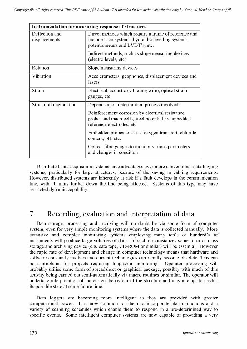
Appendix 5: Monitoring 130
Instrumentation for measuring response of structures Deflection and displacements
Direct methods which require a frame of reference and include laser systems, hydraulic levelling systems, potentiometers and LVDT’s, etc. Indirect methods, such as slope measuring devices (electro levels, etc)
Rotation Slope measuring devices
Vibration Accelerometers, geophones, displacement devices and lasers
Strain Electrical, acoustic (vibrating wire), optical strain gauges, etc.
Structural degradation Depends upon deterioration process involved :
Reinforcement corrosion by electrical resistance probes and macrocells, steel potential by embedded reference electrodes, etc. Embedded probes to assess oxygen transport, chloride content, pH, etc. Optical fibre gauges to monitor various parameters and changes in condition
Distributed data-acquisition systems have advantages over more conventional data logging
systems, particularly for large structures, because of the saving in cabling requirements. However, distributed systems are inherently at risk if a fault develops in the communication line, with all units further down the line being affected. Systems of this type may have restricted dynamic capability. 7 Recording, evaluation and interpretation of data
Data storage, processing and archiving will no doubt be via some form of computer system; even for very simple monitoring systems where the data is collected manually. More extensive and complex monitoring systems employing many ten’s or hundred’s of instruments will produce large volumes of data. In such circumstances some form of mass storage and archiving device (e.g. data tape, CD-ROM or similar) will be essential. However the rapid rate of development and change in computer technology means that hardware and software constantly evolves and current technologies can rapidly become obsolete. This can pose problems for projects requiring long-term monitoring. Operator processing will probably utilise some form of spreadsheet or graphical package, possibly with much of this activity being carried out semi-automatically via macro routines or similar. The operator will undertake interpretation of the current behaviour of the structure and may attempt to predict its possible state at some future time.
Data loggers are becoming more intelligent as they are provided with greater computational power. It is now common for them to incorporate alarm functions and a variety of scanning schedules which enable them to respond in a pre-determined way to specific events. Some intelligent computer systems are now capable of providing a very
Copyright fib, all rights reserved. This PDF copy of fib Bulletin 17 is intended for use and/or distribution only by National Member Groups of fib.

fib Bulletin 17: Management, maintenance and strengthening of concrete structures 131
powerful real time context dependent response to structural monitoring data. They may utilise various technologies including knowledge-based systems and neural networks. The systems generally offer the ability to encapsulate knowledge and rules which provide a basis for evaluating the monitoring data. These systems seek to emulate (in part) those actions which would be taken by the engineer reviewing the data and assessing its implications. In broad terms such systems are likely to undertake a number of the following tasks, depending on the level of sophistication of the system and the complexity of the structural circumstances:
• Sensor validation
establishing that the output from the sensor(s) is plausible
• Presentation showing behaviour(s) in graphical form. • Rule of thumb
checking evaluating whether observed structural behaviour complies with selected simple rules for general engineering performance (e.g. deflection / span ratio).
• Prediction estimating some aspect of future condition on the basis of current or recent trends in behaviour and comparing this with pre-defined limits.
In the future it is expected that intelligent systems of this type will be able to interact with
the human operator and be able to utilise aspects of the results from advanced analyses of structural behaviour. 8 Reporting of results and responsibilities
Those commissioning and carrying out programmes of structural monitoring need to establish at the outset their respective duties, obligations and responsibilities not only during the development and installation phases, but also during the term of the monitoring programme. Obligations concerning the frequency of review of the data and subsequent reporting need to be clearly established, especially if these may change in certain circumstances (eg. in anticipation of or following a severe storm). Experience has shown that monitoring systems, particularly long-term ones, require high-quality documentation describing the operation of the system installed and the basis for interpreting the data gathered. It is essential than someone maintains an overview of the behaviour of the structure, remedial actions and related matters.
It is also crucial to consider at an early stage how the large volumes of data which inevitable are produced during a monitoring exercise, particularly ones which are both intensive and utilise automated or autonomous systems, are to be handled, archived and processed into useful information upon which decisions can be made. It is all too easy for those managing a monitoring system to ‘drown’ in data output and figures of various sorts, without achieving an adequate understanding of what the data is actually indicating about the behaviour of the structure concerned.
Copyright fib, all rights reserved. This PDF copy of fib Bulletin 17 is intended for use and/or distribution only by National Member Groups of fib.

Appendix 5: Monitoring 132
9 Bibliography [1] Moore JFA (ed), “Monitoring of Building Structures”, Blackie, 1992. [2] Proceedings of the Second International Conference on Bridge Management
“Inspection, Maintenance, Assessment and Repair”, University of Surrey, Guildford, UK, 18-21 April 1993. Thomas Telford, London. ISBN 0-7277-1926-2.
[3] Proceedings of the Third International Conference on Bridge Management “Inspection, Maintenance, Assessment and Repair”, University of Surrey, Guildford, UK, 14-17 April 1996. E and F N Spon, London. ISBN 0-419-21210-8.
[4] Proceedings of the International Conference “Repair of Concrete Structures - From Theory to Practice in a Marine Environment”, Svolvær, Norway, 28-30 May 1997. Norwegian Road Research Laboratory. ISBN 82-7207-435-4.
Copyright fib, all rights reserved. This PDF copy of fib Bulletin 17 is intended for use and/or distribution only by National Member Groups of fib.

fib Bulletin 17: Management, maintenance and strengthening of concrete structures 133
APPENDIX 6
Fire
Copyright fib, all rights reserved. This PDF copy of fib Bulletin 17 is intended for use and/or distribution only by National Member Groups of fib.
Appendix 6: Fire 134
Contents
1 Introduction 135
1.1 General 135
1.2 Fire safety requirements 135
1.3 Fire engineering 136
1.4 Estimation of fire severity 137
1.5 Behaviour as a structural system 138
2 Assessment of the effects of fire 138
2.1 Effects of high temperature upon structural materials 139 2.1.1 Behaviour of concrete 139 2.1.2 Behaviour of reinforcing and prestressing steels 143
2.2 Effects of high temperature upon structural members 146
2.3 Procedure for appraisal 147
2.4 Initial site visit and desk study 147
2.5 Collection of site data 148
2.6 Assessment of damage 149
3 Repair of structure 151
3.1 Methods and strategies of repair 151
3.2 Repair design 151
4 Acknowledgements 151
5 References 151
Copyright fib, all rights reserved. This PDF copy of fib Bulletin 17 is intended for use and/or distribution only by National Member Groups of fib.

fib Bulletin 17: Management, maintenance and strengthening of concrete structures 135
1 Introduction 1.1 General
After a fire has occurred there is generally a need to rapidly carry out an assessment of the degree of damage and the measures required to return the building or structure to service as soon as possible. The loss of the use of the facility can have severe financial implications for the owners and occupiers. In addition to the technical requirements for the repair or reinstatement of the building or structure, consideration may need to given to other related factors influencing the economic viability of these actions. These considerations may include aesthetics and issues of future durability and performance, as well as the views of the insurers and the immediate client for the work. The technical feasibility and associated estimates of cost may provide a basis against which these matters can be evaluated. Judgements may have to be made upon the suitability of reinstatement by various methods of repair or by demolition and rebuilding of elements or effected parts of the structure.
Many of the comments made in this Appendix are presented in the context of building structures, which is where the greatest proportion of fire damage tends to occur. However significant fire losses can also occur in other forms of structure, such as tunnels and bridges. Whilst these experiences are rare, they can be very serious and cause considerable damage and disruption. Accordingly the possibility of such an occurrence should not be overlooked, nor should the potential implications of such an event. 1.2 Fire safety requirements
Fire safety considerations cover a wide range of issues. However essential to these are the goals of:
• the safe evacuation of users of the building or structure during a fire emergency, • minimising hazards to firefighters responding to such an emergency, and • the control of the spread of fire.
Some of these measures may take an active form which respond to the threats posed by the fire, such as the use of sprinklers, and others may involve the more traditional materials-based passive response to ensuring fire safety. In all cases it is necessary to develop a plan for the overall management of the structure.
Whilst these considerations fall outside the scope of this document, it is appropriate to briefly consider the performance requirements which may be placed upon structural elements, depending upon their circumstances within the structure concerned. Fire resistance or endurance over a period of time essentially consists of three components:
• loadbearing capacity and stability of structural members • integrity, that is the control of transmission of hot gases, and • insulation, which concerns the control of heat transfer.
It is important to realise that there may be different performance requirements for different
structural members. For example, columns would normally only be required to remain stable and retain an adequate load capacity. They would therefore need a fire performance /
Copyright fib, all rights reserved. This PDF copy of fib Bulletin 17 is intended for use and/or distribution only by National Member Groups of fib.

Appendix 6: Fire 136
protection commensurate with these objectives. However, other elements such as floors and walls would typically be expected to achieve a defined performance in respect of all three of the given criteria. There may also be circumstances where the structural capabilities of an element may not be significant to the fire case being considered. For example, a wall or diaphragm may only need to provide a barrier against the transmission of heat and gases. In addition, consideration may need to be given to the effects of heating of a particular member and the associated expansion forces upon the behaviour or performance of elements remote from the fire. Accordingly it may be necessary to provide fire protection to particular members to assure the performance of others remote from the fire, such as beams to avoid the creation of lateral forces which could destabilise walls, panels, columns or other members remote from the fire.
It is of course advisable for assessments of fire risk to be made prior to a conflagration
occurring. In doing this it is important to seek to appreciate how the structure might respond and potentially fail in envisaged fire scenarios. It is also important to evaluate what the consequences of that failure might be to the people using the structure and for the associated economic activities which the building or structure is used to perform. To do this in more complex circumstances it may be advisable to seek specialist fire engineering advice. 1.3 Fire engineering
In addition to the evaluation of damage to a structure after a fire, it may be appropriate to make an assessment of fire safety prior to a fire occurring. This can be approached in a number of ways. To do this effectively it is necessary to establish the fundamental reasons and criteria for undertaking the study prior to embarking upon the exercise. The principal methodologies involve one of the following approaches [1].
1. Prescriptive approach : directly following the recommendations of international or national standards and guidance documents where these are available.
2. Qualitative approach : seeking to develop a logically consistent method, supported as necessary by simple calculations, based upon recognised criteria to ensure satisfactory performance during a fire.
3. Quantitative approach : involving the preparation of detailed assessment calculations using analytical modelling and, potentially, experimental studies.
Depending upon circumstances and national regulatory requirements, there may be no
need for an existing building or structure to comply with modern standards (see below). However if such an assessment is made it is usual to identify where and how existing building or structure does not comply with these standards and to report to the client the potential implications of any non-compliance. It may be appropriate to evaluate the benefits that might be gained by reducing the risk of failure of the more sensitive or critical elements in the structure. The use of risk management or value engineering principles may be of assistance when seeking to undertake such an evaluation.
Current codes of practice for the design of concrete structures, such as ENV Eurocode EC2 Part 1.2 [2], generally utilise simple prescriptive rules. Alternative more flexible design
Copyright fib, all rights reserved. This PDF copy of fib Bulletin 17 is intended for use and/or distribution only by National Member Groups of fib.

fib Bulletin 17: Management, maintenance and strengthening of concrete structures 137
approaches have been suggested [3] for estimating flexural and shear capacities of reinforced beams exposed to fire utilising the standard time-temperature relationship [4].
1.4 Estimation of fire severity The intensity of fires in actual buildings or structures, that is the time-temperature
relationship, depends upon a number of factors [5]. These include the amount and type of the combustible material present, its combustion characteristics and how the material is stacked, dimensions of the enclosure, thermal properties of the ceiling and walls bounding the enclosure, but most importantly by the amount of ventilation. Wind effects can also be important.
These factors not only vary considerably between different buildings and structures, but
also there may be substantial variations within a single structure and even within an individual fire compartment. Fires are therefore unlikely to be of uniform intensity throughout the structure. Specialist knowledge is needed to be able to take account of these factors, as perhaps might be attempted in a pre-fire risk assessment. However, it is unlikely that it would be worthwhile to seek to make estimates of the time-temperature relationship for individual structural elements, although this might be possible for selected ‘key’ members for particular fire scenarios.
An approach that has been used in these circumstances is to seek to characterise a fire
scenario in terms of the period of exposure to the standard fire [6] to produce the same internal temperature at some point within the structural member being considered.
Examination of the debris following a fire gives an indication of local conditions. The
literature [5, 7] provides information upon the effects of temperature on various materials; noting the approximate temperatures at which conditions such as charring, bubbling, softening, melting, drop formation and the like may be expected to occur. In addition, the literature [1, 5, 7] also provides information on ignition and auto-ignition temperatures of various materials. However it is necessary to consider whether such indications are likely to give a true indication. Timber may continue to char after primary extinguishment. Detached materials found in the debris may produce over-estimates of exposure due to prolonged or unusual heating conditions. For the purposes of the assessments that are the focus of this report, emphasis should be placed upon the melting of metals and the colour changes occurring in concrete of structural members. However it should be realised that estimates derived may be subject to significant variation, which may in part represent the natural variability which occurs in these situations.
Further explanation of the physics of fires, the behaviour of materials, the spread and
behaviour of fires within buildings, means of predicting fire resistance of structural elements, economic issues associated with fires and various other related matters is given within the literature [8].
Copyright fib, all rights reserved. This PDF copy of fib Bulletin 17 is intended for use and/or distribution only by National Member Groups of fib.

Appendix 6: Fire 138
1.5 Behaviour as a structural system Whilst the fire resistance of isolated structural elements may appear to be inadequate, the
influence and beneficial effects of structural continuity should not be overlooked. A damaged or overloaded member will have an ability to shed load to adjoining members in a continuous structure. This continuity may not have been taken into account in the design of the members or in the sizing of the reinforcement, possibly resulting in some degree of over-provision in the original loadbearing capacity. The element in question could also be part of a redundant structural system, so the effect of its failure upon the overall behaviour and stability of the structural system may not be significant. Special consideration should be given to the behaviour and performance of critical members, as their influence on overall behaviour and robustness could be disproportionally important. 2 Assessment of the effects of fire
Fires in buildings and structures typically reach temperatures in the order of 1000°C. Dense concrete and the embedded steel with which it is reinforced are essentially non-combustible materials. Heating by fire can affect the loadbearing capacity of such structures in a number of ways. These arise by a combination of temporary and permanent effects upon the physical and structural engineering properties of the materials concerned, the interaction of the component materials, the elements and the structural system within which they are incorporated.
The assessment of fire damage to structural concrete members will generally involve consideration of the:
• temperature developed during the fire; • duration of the fire; • temperatures reached within the members concerned; • effect of the temperatures whilst hot and after cooling on the structural engineering
properties of the concrete and steel; • significance that any permanent changes in the material properties may have upon the
future structural performance and durability of the elements and parts of the structure affected;
• assessment of the extent of damage; and • feasibility and cost of alternative repair options to compensate for unacceptable
reductions in strength, stiffness, durability or other performance criteria for individual elements or the overall structure.
The behaviour of particular forms of construction, such as wood wool permanent shuttering for floor slab construction [9], may require special consideration and knowledge.
The process of making the assessment will typically involve :
• the collection of event data; • damage assessment; • damage classification; • review of repair criteria and options, and • selection of most appropriate repair /reinstatement method(s).
Copyright fib, all rights reserved. This PDF copy of fib Bulletin 17 is intended for use and/or distribution only by National Member Groups of fib.

fib Bulletin 17: Management, maintenance and strengthening of concrete structures 139
Materials consumed in the fire may release chlorides and other contaminants [5]. For example, chlorides are released during the decomposition of plastics containing polychlorides (eg. PVC). Acids may also be produced. The contaminants may attack the concrete or reinforcement during the fire, or subsequently. In some parts of the world saline water may be used for fire fighting purposes. In the case of chloride ions, they will initially form a surface contaminant but with time the must be expected to penetrate deeper into the members concerned potentially promoting corrosion of embedded reinforcement and prestressing steel. Cleaning of the affected surfaces soon after the fire should be considered. Future performance and durability of the member(s) will depend upon a number of factors, including material properties and environmental conditions. 2.1 Effects of high temperature upon structural materials 2.1.1 Behaviour of concrete
Whilst room air temperatures in a fire are likely to be in the order of 1000°C, the temperatures attained within a concrete member will be much less. As concrete has a low thermal conductivity, only the temperature of the outer layers is increased dramatically. Thermal conductivity tends to decrease with increased temperature, through the loss of pore water and dehydration of the cement paste. As long as this material remains in place it effectively acts as an insulating surface layer. This gives concrete elements their inherently good fire resistance.
However this surface heating creates severe temperature gradients, thermally induced stresses
and raised internal (pore) vapour pressures in the members so affected, causing varying degrees of cracking and spalling. The internal temperatures developed depend not only on the intensity and duration of the fire, but also on the exposure condition, the section shape and type of member being considered. Figure 1 illustrates the nature of the results obtained for a 380 mm
Fig. 1: Temperature distributions in 380 mm square column at various times from start of standard BS furnace test [7]
Copyright fib, all rights reserved. This PDF copy of fib Bulletin 17 is intended for use and/or distribution only by National Member Groups of fib.

Appendix 6: Fire 140
square concrete column exposed to heat on all faces. The literature [1, 5, 7] provides guidance on temperature distributions achieved in other circumstances.
As heating progresses above about 100°C the physically combined water contained within the concrete is released. At this stage the strength is not greatly reduced, but the elastic modulus may be decreased by some 10-20%. Above about 300°C the silicate hydrates decompose and above 500°C the calcium hydroxide (portlandite : Ca(OH)2) will be dehydrated. These actions result in a breakdown in the structure of the concrete matrix causing loss of strength, a reduction in elastic modulus and an increase in the rate of creep deflection. At temperatures above 600°C some aggregates begin to convert or decompose. Fig. 2 shows the deterioration of concrete subjected to heating under standard fire conditions. Concrete exposed to temperatures in excess of 500°C may contain a considerable amount of calcium oxide (CaO). This will expand upon subsequent exposure to moisture, potentially causing cracking.
Fig. 2: Breakdown of concrete under exposure to a standard fire [5]
Creep becomes significant at relatively low temperatures, but this can have beneficial effects by relaxing existing or temperature-induced stresses.
Further reductions in engineering properties may occur after cooling. In the case of elastic modulus this may amount to a total of 40% after exposure to temperatures of 300°C and possibly 85% for 600°C. However these effects are likely to be less significant than other influences. Further details are given in the literature [1, 5, 7].
It is generally recognised that the compressive strength of concrete is little affected by temperatures up to about 300°C, but that exposed to temperatures above 600°C is unlikely to have any useful strength – refer fig. 3. As indicated the colour of concrete can change as a result of heating. The engineering properties of normal coloured concrete will have been largely unaffected by heating effects. Conversely pink coloured concrete whilst being apparently sound, its strength and elastic modulus will have been significantly reduced. Whitish-grey and buff coloured concrete will be weak and friable.
Copyright fib, all rights reserved. This PDF copy of fib Bulletin 17 is intended for use and/or distribution only by National Member Groups of fib.

fib Bulletin 17: Management, maintenance and strengthening of concrete structures 141
Fig. 3: Typical effect of heating upon the compressive strength and colour of dense siliceous aggregate concrete (NB. May not apply to calcareous or flint aggregate concrete [7]
The change in colour can be used as a clue to the maximum surface temperature attained and the equivalent fire duration [10] – refer figure 4. Interpretation will depend upon whether spalling of the surface has taken place and the time at which this is likely to have taken place during the progress of the fire. A judgement will have to be made as to whether this occurred during the period of maximum heat or subsequently. Reference can also be made to measured temperature distributions for elements exposed to heat in accordance with standard temperature – time relationships for standardised furnace fire tests – refer figure 1. The internal boundary of the pink colouration is typically taken as the 300°C isotherm, its depth can be used to estimate the equivalent duration of heating under an standard furnace fire.
Fig. 4: Estimation of equivalent fire severity by depth of colour change in concrete [10]
Copyright fib, all rights reserved. This PDF copy of fib Bulletin 17 is intended for use and/or distribution only by National Member Groups of fib.

Appendix 6: Fire 142
The extent of colour change varies with the type of coarse and fine aggregate. The pink discolouration that occurs is due to the presence of ferrous salts and is brought about by a change in their hydration states. The effect tends to be more prominent with siliceous aggregates. Calcareous and igneous crushed rock aggregates are less likely to show this effect. Whilst wetting the affected concrete will enhance the colours making subtle changes easier to discriminate, mapping the discolouration boundary can be difficult. It should be recognised that concrete which has not turned pink is not necessarily undamaged by fire; ferrous salts may not be present.
Care should be exercised to ensure that any pink colouration is not confused with the effects of carbonation of the concrete, which can be checked by testing with phenolphthalein indicator solution or by microscopy methods. There is some evidence to suggest that carbonation occurs at a faster rate after a more severe fire. Figure 5 illustrates a relationship derived between the measured depth of carbonation some 3 to 4 years after a fire and the severity of the fire. This would be expected to have an adverse effect upon the potential durability of a concrete structure in an environment that would promote the corrosion of steel embedded in carbonated concrete. Fig. 5: Depth of carbonation some 3 to 4 years after exposure of to fires of varying severity [5]
There are two main types of spalling [5, 7, 11] - explosive spalling and sloughing-off of the surface. Explosive spalling appears to occur mainly on columns and beams within about 30 minutes of exposure to heat and for a limited range of moisture contents and stress levels. It seems to be related to the ability of the concrete to dissipated steam generated from free and bound water contained within the concrete. Explosive spalling proceeds with a series of violent disruptions removing localised shallow layers. Sloughing-off is a non-violent gradual separation that occurs mainly in beams and columns. It occurs when cracks form parallel to the surface at a plane of weakness, such as a layer of reinforcement. Spalling effectively increases the rate of heat transmission into the member(s) concerned.
Copyright fib, all rights reserved. This PDF copy of fib Bulletin 17 is intended for use and/or distribution only by National Member Groups of fib.

fib Bulletin 17: Management, maintenance and strengthening of concrete structures 143
Exposure to high temperatures, together with subsequent cooling, usually causes cracking in concrete elements. This arises because of differential rates of thermal expansion between steel and concrete, leading to bursting stresses around reinforcing bars, and between aggregate particles and the concrete matrix, leading to surface crazing. Rapid heating and cooling creates non-linear thermal gradients across the member cross-section, altering the internal stress-state and curvatures of members [12]. Through-section cracking occurs particularly where free movement is constrained, perhaps by other structural elements.
Sudden cooling by water from firehoses can create surface cracking, which may be severe. The quenching action of cold water can cause more damage than the fire. Cracks may form parallel to the surface of a concrete member, potentially causing spalling of the concrete cover.
Many cracks will largely close on cooling and as member deformations reduce, unless free contraction is not possible.
If the moisture content of lightweight concrete is sufficiently low, its lower thermal conductivity means that it will often perform better than normal dense concrete in respect of cracking and spalling.
In the case of High-Alumina Cement (also known as Calcium Aluminate Cement) concrete, the action of heat and water in combination with the small cross-sectional dimensions of most of the structural elements made with the material, may exacerbate existing loss of strength and durability concerns. Specialist technical advice may be required to assess such members. 2.1.2 Behaviour of reinforcing and prestressing steels Significant loss of strength occurs in both reinforcing and prestressing steel exposed to high temperatures [1, 5, 7, 13] – refer figures 6 and 7. This reduction is usually responsible for any excessive residual deflections of members.
Fig. 6: Yield strength of reinforcing steels at room temperature after heating to an elevated temperature [7]
Copyright fib, all rights reserved. This PDF copy of fib Bulletin 17 is intended for use and/or distribution only by National Member Groups of fib.
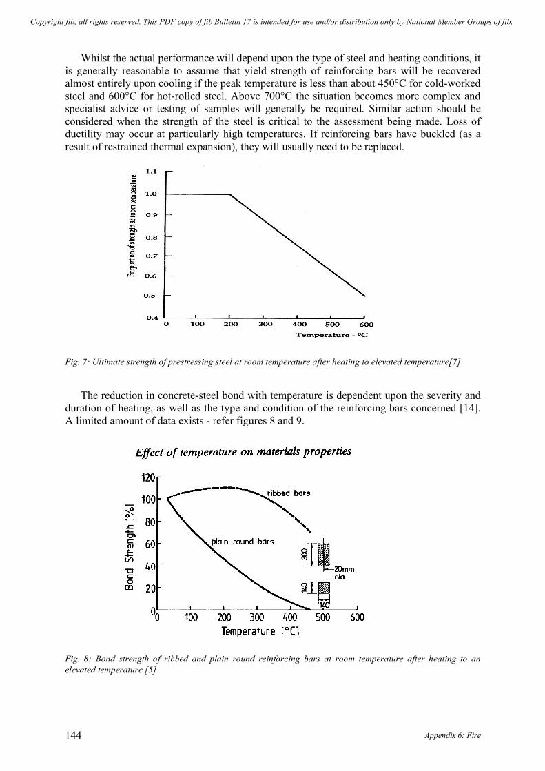
Appendix 6: Fire 144
Whilst the actual performance will depend upon the type of steel and heating conditions, it is generally reasonable to assume that yield strength of reinforcing bars will be recovered almost entirely upon cooling if the peak temperature is less than about 450°C for cold-worked steel and 600°C for hot-rolled steel. Above 700°C the situation becomes more complex and specialist advice or testing of samples will generally be required. Similar action should be considered when the strength of the steel is critical to the assessment being made. Loss of ductility may occur at particularly high temperatures. If reinforcing bars have buckled (as a result of restrained thermal expansion), they will usually need to be replaced.
Fig. 7: Ultimate strength of prestressing steel at room temperature after heating to elevated temperature[7]
The reduction in concrete-steel bond with temperature is dependent upon the severity and duration of heating, as well as the type and condition of the reinforcing bars concerned [14]. A limited amount of data exists - refer figures 8 and 9.
Fig. 8: Bond strength of ribbed and plain round reinforcing bars at room temperature after heating to an elevated temperature [5]
Copyright fib, all rights reserved. This PDF copy of fib Bulletin 17 is intended for use and/or distribution only by National Member Groups of fib.

fib Bulletin 17: Management, maintenance and strengthening of concrete structures 145
At elevated temperature the mechanical properties of prestressing steels deteriorate more rapidly than those of reinforcing steels, with the strength of tendons being reduced to less than 50% when steel temperatures reach about 400°C – refer figure 7. This shows the ultimate strength of prestressing steel at room temperature after heating to an elevated temperature.
Perhaps more significantly heating reduces the elastic modulus of the concrete, increases
creep and relaxation effects and causes non-recoverable extensions in the tendon – note the reduction in the limit of proportionality (i. e. the stress above which plastic elongation occurs) varies with temperature as shown in figure 10. This may lead to an appreciable loss of tension in prestressing tendons. This may be further reduced by the relaxation that occurs with time spent at elevated temperature – refer figure 11.
Fig. 9: Relative bond strength of various types of reinforcing bars as a function of temperature [5]
Fig. 10: Tensile tests on untreated 0.76 % carbon steel wire at elevated temperatures [7]
Copyright fib, all rights reserved. This PDF copy of fib Bulletin 17 is intended for use and/or distribution only by National Member Groups of fib.

Appendix 6: Fire 146
Fig. 11: Temperature effects upon the relaxation of untreated cold-drawn prestressing wire [7] 2.2 Effects of high temperature upon structural members
The following table summarises the event cycle and observable features that are likely to develop in a reinforced structure subjected to a period at elevated temperature. Stage Probable Effects On Heating 1: Rise in surface temperature 2: Heat transfer to interior
3: Heat transfer to reinforcement (accelerated by spalling)
Surface crazing Loss of concrete strength, cracking and spalling Reduction in yield strength, possible buckling of bars and increase in deflection of member. If any prestressing wires / tendons have been exposed by spalling they are likely to have experienced appreciable loss of tension - perhaps requiring member replacement.
On Cooling 4: Reinforcement cools 5: Concrete cools
Recovery of yield strength appropriate to the maximum temperature experienced Cracks close up, reduction in strength until normal temperature reached, partial recovery of deflections, further deterioration and damage may develop as concrete absorbs atmospheric moisture
Copyright fib, all rights reserved. This PDF copy of fib Bulletin 17 is intended for use and/or distribution only by National Member Groups of fib.

fib Bulletin 17: Management, maintenance and strengthening of concrete structures 147
2.3 Procedure for appraisal The procedure following a fire would typically involve : • An initial site visit to make a preliminary assessment of the damage • A desk study • The detailed collection of site data and other evidence • The assessment of damage • Review of repair options and the development of a specification for the repairs
The focus and scope of the appraisal would depend on the extent and degree of damage.
The objective could be to make an assessment in respect of a localised fire, perhaps only involving damage to a few members. Alternatively, there could be a need to undertake a more comprehensive evaluation to assess the overall stability of a complete building or structure following a severe and extensive fire.
Figure 12 illustrates the appraisal procedure envisaged in reference [5] indicating the decisions that may need to be made and showing the steps which may be involved. 2.4 Initial site visit and desk study
Once it is safe to enter the scene of a fire, it is necessary to gather information that will give an understanding of the history of the fire and the extent and severity of damage which has been caused to the building or structure. This assessment should be undertaken before debris is removed. The blackened and spalled surfaces, together with features such as exposed reinforcement, generally appear much worse than the actual state of the structure. Accordingly it is necessary to remain objective and seek to achieve a balanced view of the circumstances encountered. It is useful to develop at an early stage schedules of the most badly effected elements and an initial estimate of the extent of this damage.
It is also necessary to obtain drawings and details about the construction of the structure concerned, subsequent modifications or technical reports about its condition prior to the fire. Witness and fire officer reports should provide valuable insight into the history of the fire.
Charring of structural section timber exposed to the fire and which has remained in place
(ie. it is not part of the debris) can also be used as an indicator of the duration of a fire in terms of the standard furnace fire test. For many structural species of timber the char depth increases at a rate of some 40mm per hour in the standard furnace fire test. This rate can, by linear interpolation / extrapolation, be used to provide a rough guide for fires of between about 15 and 90 minutes duration. The literature provides more information upon notional charring rates in other timber species [1, 5, 7].
Copyright fib, all rights reserved. This PDF copy of fib Bulletin 17 is intended for use and/or distribution only by National Member Groups of fib.

Appendix 6: Fire 148
Fig. 12: Assessment procedure for fire damaged structures [5]
2.5 Collection of site data
A range of information needs to be carefully gathered. This may include : • char depths in structural timber (if present – see above) • estimates of the depth to the 300°C isotherm in selected concrete members • material samples for laboratory testing • non-destructive testing performed upon selected members • a visual examination and classification of damage to each structural member using the
Copyright fib, all rights reserved. This PDF copy of fib Bulletin 17 is intended for use and/or distribution only by National Member Groups of fib.

fib Bulletin 17: Management, maintenance and strengthening of concrete structures 149
convention set-out in chapter 2.6 below. Typically summary plans and schedules detailing the damage to individual members will be prepared so that an overview of the situation can be obtained.
It may be sufficient for the examination of the fire-damaged structure to be undertaken
simply by visual examination and the use of ‘sounding’ to determine the extent of damaged concrete, with local excavations being made into members to establish the depth of pink discolouration. ‘Sounding’ by means of a steel hammer rapidly enables delaminated material and zones of weak concrete to be distinguished from competent material. Small diameter cores may be needed for the identification of the depth of pink discolouration.
The use of general testing and investigation techniques is discussed in chapter 2.5 of the main report. However two additional laboratory tests may be of particular assistance in the assessment of fire damage. The number of laboratories able to undertake these tests may be limited.
• Thermoluminescence (TL) testing [15, 16, 17] can be used to estimate the temperature to which concrete has been exposed in a fire. TL is the emission of visible light from minerals, which occurs when they are heated. This process releases energy stored in the minerals. Once released, subsequent reheating will not produce further TL emissions until continued exposure to natural radiation has built up the stored energy again. TL output depends upon the temperature to which the sample has been exposed and the time of heating. A series of incremental concrete dust samples could be used to derive the temperature–depth profile experienced during the fire. Thus the TL signal remaining in samples of quartz sand extracted from dust samples gives a good indication of damage from exposure to temperatures between 300 and 500°C. This can be used to estimate when the concrete has lost a significant proportion of its strength.
• A chemical analysis [5] can be carried out to establish the residual bound water ratio. The method involves recovering a series of concrete dust samples at increasing depth into the member concerned in order to give an incremental profile. These are prepared and then heated to determine the amount of chemically bound water in the cement paste remaining after heating by the fire. This enables the temperature gradient experienced to be established, and hence an estimate made of the reduction in strength with depth.
If the results of the various testing and analysis methods are largely in agreement, the assessment of damage can be approached with a greater degree of confidence. The search for additional and improved procedures for the evaluation of fire damage continues [18]. 2.6 Assessment of damage The following provides a resume of the states of damage recognised in the literature. A more detailed classification and characterisation of damage to concrete columns, beams / girders, floors and walls and prestressed beams and floor components is given in reference [5].
Copyright fib, all rights reserved. This PDF copy of fib Bulletin 17 is intended for use and/or distribution only by National Member Groups of fib.

Appendix 6: Fire 150
Class Characterisation Description 1 Cosmetic damage to
surfaces Characterised by soot deposits, discolouration of surfaces and odour. Concrete not damaged except possibly for some surface crazing. Repairs : Essentially redecoration. Soot and colour effects can often be removed by cleaning, but these may cause problems on high-quality finishes. Odours may be difficult to remove.
2 Superficial damage to surfaces
Characterised by damage to surface treatments, finishes and coatings. Concrete largely undamaged, except for surface crazing and limited amounts of isolated concrete spalling. Concrete discoloured. Repairs : Primarily reinstatement of coatings. Larger spalls repaired by cosmetic mortar surface infill, but minor spalls may remain.
3 Minor structural damage to surfaces
Characterised by some concrete cracking and more extensive spalling, especially along and around edges leaving some reinforcement exposed. Surfaces heavily sooted and surface treatments / finishes totally damaged. Concrete probably discoloured to buff. Structural capacity of elements not significantly reduced, bond between concrete and steel intact. Repairs : Non-structural or minor structural repairs necessary to restore cover to reinforcement where lost. Procedures similar to those for class 2.
4 Structural damage to interior of member cross-section
Characterised by major cracking and spalling, with significant lengths of reinforcement exposed. Deflections / deformations may be large enough to diminish loadbearing capacity of members. Bond between concrete and steel affected in local zones. Fire products may have caused significant acidic deposition on surface of concrete. Repairs : Damage repairable, but involves reinstating / enhancing structural capacity to meet loadbearing requirement for particular member. Choice of technique depends upon circumstances – refer Section 3 below.
5 Structural damage to elements and components
Characterised by severe damage to structural elements, extensive spalling causing reduction in cross-sectional area, almost all reinforcement exposed in member, impaired materials (appreciable reductions in concrete compressive strength, buckling of reinforcing bars and severe reductions in concrete-steel bond) and appreciable deformations of structural elements. Repairs : Major repair necessary, could require demolition and reconstruction. Repair might be effected around remnant of original member, but with concrete and reinforcement assumed to have zero strength.
Consideration also needs to be given to the future durability of affected members which may have been exposed to aggressive contaminants, such as acids and chlorides, or have experienced cracking or crazing potentially leading to faster rates of carbonation or deterioration after the fire. Relative risk indexes may be assistance in such an evaluation.
Copyright fib, all rights reserved. This PDF copy of fib Bulletin 17 is intended for use and/or distribution only by National Member Groups of fib.

fib Bulletin 17: Management, maintenance and strengthening of concrete structures 151
3 Repair of structure 3.1 Methods and strategies of repair
General principles for the repair and reinstatement of damaged or deteriorated concrete structures are discussed in Chapter 4 of the main report. The approach adopted has followed that set down in European Standard ENV 1504 : Part 9 : Products and systems for the protection and repair of concrete structures. Traditionally sprayed mortar (gunite) and concrete has been used to undertake many structural repairs following a fire. The literature Error! Bookmark not defined.discusses the approaches that have been found to be successful and draws attention to particular issues that may need to be considered in a fire damaged structure. 3.2 Repair design
The literature [7] provides details of repair configurations that may be useful when seeking to effect structural repairs and draws attention to particular issues that may need to be considered in a fire damaged structure. 4 Acknowledgements
The contents of this appendix draw heavily upon the literature, in particular the extremely valuable reports produced by The Concrete Society [7] and by CIB [5]. The useful comments made by Mr Tony Morris and Dr Pal Chana, both of BRE, are gratefully acknowledged. 5 References [1] Appendices 5 and 6, Appraisal of existing structures : 2nd Edition; Institution of
Structural Engineers, London, October 1996 [2] British Standards Institution, Eurocode 2: Design of concrete structures. General rules –
Structural fire design. DD ENV 1992-1-2; British Standards Institution, Milton Keynes, 1995
[3] Desai, S. B., Design of reinforced concrete beams under fire exposure conditions; Magazine of Concrete Research, Vol 50, No 1, pp 75 - 83, June 1998
[4] British Standards Institution, BS476: 1987: Fire tests on building material structures. Part 20: Method of determination of the fire resistance of elements of construction (General principles); British Standards Institution, Milton Keynes, 1987
[5] Repairability of fire damaged structures; CIB W14 Report, edited by U Schneider, Fire Safety Journal, Special Issue, Vol 16, No 4, 1990
[6] Current Ref to standard fire (BSI / ISO etc) British Standards Institution, BS476: Part 8: 1972: Fire tests on building material structures. Part 8: Test methods and criteria for the fire resistance of elements of building construction; London, 1976, 16 pp
[7] Assessment and repair of fire-damaged concrete structures; Concrete Society Technical Report TR.033, The Concrete Society, Wrexham, Slough, UK, 1990, 77 pp
Copyright fib, all rights reserved. This PDF copy of fib Bulletin 17 is intended for use and/or distribution only by National Member Groups of fib.

Appendix 6: Fire 152
[8] Lie, T. T., Fire and buildings; Applied Science Publishers, London, 1972, 276 pp
[9] Malhotra, H. L., and Morris, W. A., An investigation into the fire problems associated with wood wool permanent shuttering for concrete floors; Current Paper CP68/78, Fire Research Station, Building Research Establishment, Garston, UK, 1978
[10] Tucker, D. M., and Read, R. E., Assessment of fire damaged structures; Information Paper IP24/81, Fire Research Station, Building Research Establishment, Garston, UK, November 1981
[11] Malhotra, H. L., Spalling of concrete in fires; Technical Report No 118, Construction Industry Research Association (CIRIA), London, 1984, 36 pp
[12] Tassios, T. P., and Chronopoulos, M. P., Structural response of RC elements under fire; The Structural Engineer, Vol 69, No 15, 6 August 1991, pp 277 - 281
[13] Holmes, M., Anchor, R. D., Cook, G. M. E., and Crook, R. N., The effects of elevated temperature on the strength properties of reinforcing and prestressing steels; The Structural Engineer, Vol 60B, No 1, pp 7 - 13, March 1982
[14] Morley, P. D., and Royles, R., Response of the bond in reinforced concrete to high temperatures; Magazine of Concrete Research, Vol 35, No 123, June 1983, pp 217 - 228
[15] Smith, L. M., and Placido, F., Thermoluminescence : A comparison with the residual strength of various concretes; ACI Special Publication SP-80 : Fire safety of concrete structures, American Concrete Institute, Detroit, 1983, pp 293 - 304
[16] Placido, F., Thermoluminescence test for fire damaged concrete; Magazine of Concrete Research, Vol 32, No 11, June 1980, pp 112 - 116
[17] Smith, L., After the fire; Construction Repairs and Maintenance, November 1985, pp 9 -10
[18] Riley, M. A., Possible new method for the assessment of fire-damaged concrete; Magazine of Concrete Research, Vol 43, No 155, June 1991, pp 87 - 92
Copyright fib, all rights reserved. This PDF copy of fib Bulletin 17 is intended for use and/or distribution only by National Member Groups of fib.

fib Bulletin 17: Management, maintenance and strengthening of concrete structures 153
APPENDIX 7
Special considerations related to seismic retrofitting
Copyright fib, all rights reserved. This PDF copy of fib Bulletin 17 is intended for use and/or distribution only by National Member Groups of fib.

Appendix 7: Special considerations related to seismic retrofitting 154
Contents
1 General 155
2 Introduction 155
3 Seismic assessment of buildings 156
3.1 Background 156
3.2 Problem areas of moment resisting frames of building structures 157
3.3 The force-based method of assessment 158
3.4 The displacement-based method of assessment 159
4 Seismic assessment of bridges 160
4.1 Background 160
4.2 Seismic retrofit philosophy 161
4.3 The force-based method of assessment for bridges 161
5 Retrofitting techniques 163
5.1 Background 163
5.2 Jacketing 164
5.3 Prestressing 167
5.4 Foundations 168
5.5 Base isolation 170
5.6 Superstructure retrofit 171
6 Conclusions 173
7 References 173
Copyright fib, all rights reserved. This PDF copy of fib Bulletin 17 is intended for use and/or distribution only by National Member Groups of fib.

fib Bulletin 17: Management, maintenance and strengthening of concrete structures 155
1 General This appendix describes the particular matters relating only to the maintenance and
retrofitting of structures in earthquake prone regions. Separate sections on assessment of buildings and bridges are included, however, remediation methods cover all types of structures.
2 Introduction With the realisation that reinforced concrete structures designed between the 1920s and
1960s are often deficient in terms of seismic requirements of existing codes, there has recently been an increased emphasis on retrofitting buildings and bridges to enhance their seismic performance. In many countries, codes have only recently required design for seismic effects and hence there has been a move to upgrade structures to provide some degree of earthquake resistance.
The emphasis in these retrofit projects, now accepted worldwide, has been the provision of additional lateral load strength and/or lateral deformation capacity to bring structures to, or near to, current code requirements at the same time, setting down criteria for the realistic assessment of existing structures to be made. The decision to retrofit has been typically made on the basis of a check-list assessment of details compared to current requirements. It is important to note that the check-list assessment procedures are purely qualitative and should only be used as a first step screening process to decide whether a detailed assessment should proceed. Prioritization schemes have been employed to rank high seismic risk bridges in a region or country, in order to optimize the allocation of resources to undertake seismic retrofitting. It is evident from detailed analysis of existing structures and performance during recent earthquakes, that not all structures designed prior to the 1970s pose significant earthquake risks, even when poor details are apparent and lateral load strength are comparatively low.
Acceptance of assessment procedures based on determination of the lateral load strength and ductility of the critical mechanism of inelastic deformation of the structure has led to practical retrofitting methods for the enhancement of the structures to be developed. By comparison with the elastic design response spectrum, the risk, in terms of annual probability of exceedance may be determined. The approach utilises recently derived analytical procedures backed up by a great deal of experimental work.
Design methods now fully tested by research institutions, relevant to different retrofit concepts include steel jacketing, use of advanced composite materials, prestressed and reinforced concrete additions, and base isolation systems.
Research in these fields is on-going and will continue indefinitely. The concepts outlined in this appendix are those which are topical in 1997 and represent a concise summary of the current state-of-the-art. A recommended reference list is attached and readers are encouraged to study the topics to obtain further details.
Copyright fib, all rights reserved. This PDF copy of fib Bulletin 17 is intended for use and/or distribution only by National Member Groups of fib.

Appendix 7: Special considerations related to seismic retrofitting 156
3 Seismic assessment of buildings 3.1 Background
Seismic design procedures have advanced significantly since about 1970. The main developments have been in the understanding of nonlinear dynamic response of structures, the introduction of capacity design procedures and the methods of detailing reinforcement in concrete structures to achieve ductile behaviour necessary to survive severe earthquakes [1, 2].
These developments have brought about the realisation that many reinforced concrete structures designed before the mid-1970s may be deficient according to the seismic requirements of current codes. As a result, there has been increasing emphasis in recent years on the assessment and retrofit of buildings to improve their seismic performance.
The need for the assessment of old reinforced concrete building structures and to retrofit has been emphasised by the damage caused by major earthquakes, the most recent examples being the 1989 Loma Prieta and the 1994 Northridge earthquake in California and the 1995 Hyogo-ken Nanbu earthquake in Japan.
Structural deficiencies are generally not just a result of low lateral load strength. Longitudinal reinforcement in many existing structures results in lateral load strength which approach or exceed that required by current codes. The poor structural response is normally due to the lack of a capacity design approach [1] often combined with poor detailing of the reinforcement. This means that the available ductility of the structure may be inadequate to withstand a severe earthquake, without collapse.
There has been increased activity in many countries on retrofitting buildings to improve seismic performance. Decisions to retrofit have usually been made by a check-list assessment, comparing details of the as-built structures with the requirements of current seismic codes. Subsequent retrofitting has been undertaken to bring the structure up to, or near to current requirements by the provision of additional strength or ductility. However, testing and research has proven that not all structures designed before the mid-1970s will respond poorly to severe earthquakes, even when according to current standards the detailing of the reinforcement in some regions is substandard.
Priestley and Calvi [3] presented a rational assessment procedure that moves away from the check-list approach and considers the overall performance of the structure. The procedure is based on determining the available static lateral load strength and ductility of the critical mechanism of in-elastic deformation of the structure. Once the available lateral load strength and ductility of the structure has been established, reference to the current code response spectra for earthquake forces for various levels of structural ductility factor enables the designer to assess the likely seismic performance of the structure.
It is worth noting that in the proposed assessment procedure, the dependency of the shear strength on the section ductility is recognised as the rotation capacity in a plastic hinge region may be controlled by shear rather than flexure.
Copyright fib, all rights reserved. This PDF copy of fib Bulletin 17 is intended for use and/or distribution only by National Member Groups of fib.

fib Bulletin 17: Management, maintenance and strengthening of concrete structures 157
More recently, Priestley has extended his discussion from the static force-based approach and formulated a static displacement-based seismic assessment procedure [4]. It is claimed that the weaknesses of the force-based approach are the assumptions of the relationship between the elastic and inelastic acceleration response spectra for various structural ductility factor levels and the emphasis on strength. In the displacement-based approach, the comparison of demand and capacity is made in terms of displacements found from displacement response spectra for different levels of equivalent viscous damping.
Park [5] points out that time-history nonlinear dynamic analysis can also be used to estimate the ductility demand and the displacement response of an existing structure to major earthquake shaking. However, hysteresis loops used in the analysis need to realistically model any strength and stiffness degradation, and pinching, of the critical regions of the structure. This method should be used cautiously as most time-history nonlinear dynamic analysis programmes are still unable to model shear failures in beams, columns or beam-column joints after flexural plastic hinges have initially formed. Furthermore, few programmes are able to provide a realistic analysis of three dimensional structures.
A method that has been widely accepted for determining the deformation capacity of a building structure is the nonlinear pushover analysis, where the lateral loads are gradually increased until the critical mechanism of inelastic deformation forms [8]. The section ductility demands in the plastic hinges of the members are compared with the available ductilities.
Outline descriptions of both the force-based and deflection based methods of seismic assessment are given below, with references to more detailed treatises on the subjects.
3.2 Problem areas of moment resisting frames of building structures Park (5) reports that examination of existing moment resisting frames typical of early
reinforced concrete buildings and observation of recent failures in earthquakes [6] indicate the major problem areas are:
• inadequate flexural strength of members, typically columns, due to insufficient
longitudinal reinforcement, • inadequate anchorage of longitudinal reinforcement due to poor anchorage details, • inadequate ductility and shear strength of potential plastic hinge regions of beams and
columns due to insufficient transverse reinforcement, • inadequate anchorage of transverse reinforcement due to poor anchorage details, • inadequate shear strength of beam-column joints due to insufficient transverse
reinforcement, • inadequate strength of footings and/or piles and their connections, • uncertain behaviour of the structure as a result of the presence of non-structural
elements, typically masonry infill walls, which can significantly alter the structural behaviour of the frame.
Copyright fib, all rights reserved. This PDF copy of fib Bulletin 17 is intended for use and/or distribution only by National Member Groups of fib.

Appendix 7: Special considerations related to seismic retrofitting 158
3.3 The force-based method of assessment The force-based seismic assessment procedure is based on determining the probable
strength and ductility of the critical mechanism of inelastic deformation of the lateral force-resisting elements. Once the available lateral load strength and displacement ductility of the structure has been established, reference to the current code response spectra for earthquake forces for various levels of structural ductility factor enables the designer to assess the likely seismic performance of the structure. Modified loadings factors and general factors are applied at appropriate stages during this process [7, 8].
Three methods are recommended for estimating the lateral load strength of a building structure. In each method allowances for concrete cracking and probable, rather than characteristic, material strengths are made when modelling the structural members. A description of each method is given below.
Method 1 - A linear elastic analysis of the structure is carried out. The structure is loaded with gravity loading and lateral loading is applied to the frames until the first plastic hinge forms. The lateral force so found represents a lower bound estimate to the lateral load strength of the building.
A sway potential index is defined and quantified to investigate whether a column sidesway mechanism will develop. The sway potential index is calculated for the beam-column joints at each horizontal level of the building structure. The sway potential index is defined as the ratio of the sum of the probable flexural strength of the beams on one floor and the probable flexural strength of the columns above and below the beams. The probable flexural strengths are taken at the joint centroids. A column sidesway mechanism is likely to develop if the sway potential index is less than one. However, given the consequences of the formation of a column sidesway mechanism, and to account for higher mode effects, it is recommended that a column sidesway mechanism will likely form when the sway potential index is less of equal to 0.85.
A limitation of this method is that it can only be used to give a lower bound estimate of the lateral load strength of a building while the actual strength may be much greater. The method cannot be used to find the location of the critical regions were plastic hinges will form nor the complete mechanism of inelastic deformation.
Method 2 - The critical mechanism of inelastic deformation is found using the upper bound theorem of the theory of plasticity. The danger of this solution is that the critical mechanism of inelastic deformation may be missed, overestimating the lateral load strength of the building. This method is recommended for simple structures where when the critical mechanism of inelastic deformation is obvious.
Method 3 - The method consists in conducting a pushover analysis. This is the most complete procedure for establishing the lateral load strength of the building. Lateral loading is applied in increments to the building. Each load increment corresponds to the formation of a plastic hinge. The analysis is completed when the mechanism of inelastic deformation has developed. At this stage the lateral load strength and the ultimate displacement of the
Copyright fib, all rights reserved. This PDF copy of fib Bulletin 17 is intended for use and/or distribution only by National Member Groups of fib.

fib Bulletin 17: Management, maintenance and strengthening of concrete structures 159
building are found. It is recommended that a sensitivity analysis be made to ensure that the appropriate distribution of the lateral force has been selected for the pushover analysis.
The base shear coefficient can be determined as the ratio between the lateral load strength of the building and the seismic weight. With methods 1 and 3, it is possible to find out the fundamental period of the building using elastic response. The structural ductility demand is found from an inelastic design response spectra for the appropriate site subsoil category by entering the fundamental period of the building and the base shear coefficient (Fig. 1).
Figure 1: Structural ductility demand
This method is so far the most appealing of the three methods proposed (8). A limitation of the method, is that it ignores the possible eccentricities between the centre of mass and the centre of rigidity. An advantage of the method is that is not so difficult to incorporate in the analysis frames with masonry infilled panels.
It is worth noting that the analysis in each of the three methods discussed above assume that the flexural strength will be developed in the critical regions where plastic hinges form and be maintained as plastic hinges rotate. For this reason the section available ductility capacity needs to be checked against the imposed demand. Recommendations are given to assess the effect of the section ductility demand in reducing the shear strength at the plastic hinge regions for beams, columns and in beam-column joints. Those regions were the imposed section ductility exceeds the available ductility need to be retrofitted. 3.4 The displacement-based method of assessment
Displacement-based methods place a direct emphasis on establishing the displacement capacity of the lateral force resisting elements. Displacement-based assessment utilises displacement spectra which can more readily represent the characteristics of real earthquakes. The development of procedures encompassing this approach represents a relatively recent development.
Copyright fib, all rights reserved. This PDF copy of fib Bulletin 17 is intended for use and/or distribution only by National Member Groups of fib.

Appendix 7: Special considerations related to seismic retrofitting 160
In 1995, Priestley developed a displacement-based procedure for reinforced concrete buildings [4]. This method has been further developed, with appropriate simplifications, to produce the following general procedure which is considered more suitable for use in a design office context. The method is outlined below.
Determine the critical mechanism of inelastic deformation and, hence, the lateral load strength of the structure. The critical mechanism can be obtained using one of the methods outlined in section 3.3. The plastic hinge rotation capacities are obtained using moment-curvature analyses and the plastic hinge lengths. The plastic rotation capacity is reduced if necessary to the value pertaining at shear failure. The storey plastic drift capacity is estimated from the plastic rotation capacities.
The ultimate displacement and the structural ductility capacity are found from the mechanism of inelastic deformation and the critical storey drift. The effective stiffness of the structure is determined with the lateral load strength and the ultimate displacement, and the corresponding effective period of vibration calculated with the effective stiffness and the mass of the structure. Then the equivalent viscous damping of the structure is obtained from the structural ductility and the type of mechanism.
The displacement demand is found from a displacement response spectra determined for the site, subsoil conditions and equivalent viscous damping for the ultimate limit state. Retrofit will be required if the displacement demand exceeds the displacement capacity.
This method has been refined further to account for torsional response [2].
4 Seismic assessment of bridges 4.1 Background
The San Fernando Earthquake of 1971, which caused extensive damage to bridge structures, became a milestone for the development of modern seismic design codes. The need to ensure a ductile response and preclude brittle failures as well as unseating of bridge girders from occurring was recognised in the early reports [21]. The more recent 1987 Whittier, 1989 Loma Prieta and 1994 Northridge earthquakes in California, and the 1995 Hyogo-ken Nanbu earthquake in Japan, showed that even bridges designed to modern codes and to codes based on elastic design could be vulnerable to earthquakes. These earthquakes have prompted the urgent need to adopt a rational design philosophy. Another important issue observed in these earthquakes was the urgent need to protect the existing bridge stock from collapsing during earthquakes. Since the use of design codes cannot be used for assessing the seismic performance of a bridge structure, new techniques are currently being reviewed and developed.
The structural deficiencies observed in bridges damaged by earthquakes are similar to those found for building structures and stated in section 3.2.
Copyright fib, all rights reserved. This PDF copy of fib Bulletin 17 is intended for use and/or distribution only by National Member Groups of fib.

fib Bulletin 17: Management, maintenance and strengthening of concrete structures 161
4.2 Seismic retrofit philosophy The philosophy for designing the seismic retrofit of a bridge, which is shown to be unable
to respond within the elastic range to an earthquake corresponding to the ultimate limit state, should be based on capacity design principles [2]. According to these principles, a kinematically admissible mechanism of inelastic deformation should develop and be maintained during the earthquake. Those regions were plastic displacements will take place should posses sufficient ductility. All other regions in the structure should be made stronger to ensure that they will remain within the elastic limit. This philosophy implies that some members may require strengthening to avoid brittle failures that limit the deformation capacity of a bridge structure.
There are several ways in which a seismic retrofit scheme may be implemented in a bridge structure to ensure sufficient deformation capacity. One option is to ensure the development of a mechanism of inelastic deformation involving the formation of plastic hinges in some members of the structure. Another possibility involves rocking of the piers at the foundation pads. A third possibility consists in designing a base isolation scheme to shift the fundamental period of the structure and add damping if required. The latter scheme is employed to lower the seismic response of the bridge. 4.3 The force-based method of assessment for bridges
Priestley et al. [2] have proposed a relatively simple force-based method for assessing the seismic performance of bridges. The method is based on pushover analyses of the individual bents of the bridge in consideration. This method is, in essence, similar to the method for assessing the seismic performance of building structures described in section 3.3.
The bents are modelled considering the effects caused by cracking of the concrete. Probable, rather than characteristic, material strengths are used when calculating the strength of the members. Samples taken from the bridge structure can be used to provide the material strengths. In addition, mill certificates can be used for determining the yield strength of the reinforcing steel.
The lateral load-lateral displacement response of the individual bents are modelled with simple elasto-plastic springs, for which the elastic stiffness, the strength and the deformation capacity of each spring is known. The springs are connected to a infinitely rigid horizontal member representing the bridge deck, for which the centre of mass is known (Fig 2). The initial lateral stiffness at the centre of mass of the bridge structure can be found from first principles, which consider the eccentricity between the centre of mass and the centre of rigidity. The fundamental period of the bridge is found with the initial lateral stiffness and the mass of the bridge.
Copyright fib, all rights reserved. This PDF copy of fib Bulletin 17 is intended for use and/or distribution only by National Member Groups of fib.

Appendix 7: Special considerations related to seismic retrofitting 162
Fig 2: Modelling of lateral load-lateral displacement response
To assess the lateral deformation capacity of the bridge, the lateral load at the centre of mass is gradually increased until one of the bents reaches the ultimate displacement. During the incremental analysis, the lateral stiffness of the structure and, therefore, the centre of rigidity, varies as the simple springs reach the elastic limit and stop contributing towards the stiffness of the structure. The nonlinear lateral load-lateral displacement response of the bridge structure obtained from the analysis is simplified with an elasto-plastic response (Fig 3). The structural ductility factor is defined from the elasto-plastic response as the ratio between the ultimate displacement and the ideal yield displacement.
The structural ductility demand can be obtained from an inelastic acceleration response spectrum, corresponding to the ultimate limit state for the site and the sub-soil conditions. (Fig 1). Retrofitting is required if the structural ductility demand exceeds the capacity. Priestley et al. [2] have extended the method to establish the risk of failure in terms of the annual probability of exceedence, which enables decisions to be made in rational terms.
Figure 3: Simplified elasto-plastic response
The limitations of the simple method are: (i) when adjacent frames have greatly different stiffness and the connection across
movement joints is adequate, the response estimated by this method may
Copyright fib, all rights reserved. This PDF copy of fib Bulletin 17 is intended for use and/or distribution only by National Member Groups of fib.

fib Bulletin 17: Management, maintenance and strengthening of concrete structures 163
overestimate the response of the more flexible frame and underestimate the response of the stiffer frames;
(ii) the analysis tends to overestimate the torsional response when compared with results obtained from inelastic time-history dynamic analyses;
(iii) the method is inappropriate for curved bridges as the analysis of the individual bents cannot be superimposed for finding the response of the entire structure.
5 Retrofitting techniques 5.1 Background
Techniques for retrofitting structural elements are the same for most types of structures. In buildings, the decision as to the overall method used to enhance the seismic performance will usually be based on a number of options, whereas a bridge structure does not have the luxury of enabling many different alternatives to be considered.
This section describes the methods currently used for the enhancement of elements, such as columns, beams, footings, cap beams and, in the case of bridges, superstructures.
Earlier experience in Japan, following the 1968 and 1978 earthquakes was centred around the provision of shear walls to increase lateral load strength of reinforced concrete buildings. This method was also employed in Mexico, but to a lesser extent after the 1985 Mexico earthquake. The disadvantage of this method is that the increase in lateral resistance is concentrated in a few places and new foundations or strengthening of existing foundations may be required to resist the increased overturning moment as well as the increased dead load of the structure.
The strengthening of columns has been the preferred method as the increased lateral load resistance is uniformly distributed throughout the structure. The use of steel bracing has similar advantages and this method has been used extensively in Japan. In bridge columns, the use of steel or composite material jackets has gained acceptance. Some work has been done on prestressed confinement (wrapping prestressing wire around a column under tension).
Increasing the shear resistance of footings has been undertaken by the casting of additional thickness to the top of the existing footing, the new concrete being tied to the old by large numbers of grouted steel dowels. Often the longitudinal steel from columns is not anchored sufficiently into the footings and this necessitates creating new connections between the two.
The philosophy for pier cap retrofitting is to force plastic hinging into the columns. Flexural enhancement of cap beams may be obtained by adding bolsters to either side of the beam, the new and old concrete being connected by dowels.
Superstructure deficiencies are likely to be either inadequate force and displacement capacities across movement joints between adjacent frames in the longitudinal direction, or flexural inadequacies to resist moments corresponding to plastic hinging.
Copyright fib, all rights reserved. This PDF copy of fib Bulletin 17 is intended for use and/or distribution only by National Member Groups of fib.

Appendix 7: Special considerations related to seismic retrofitting 164
5.2 Jacketing 5.2.1 Reinforced concrete jacketing
A jacket of new concrete containing longitudinal and transverse reinforcement may be used. The additional transverse reinforcement will increase the shear strength and the ductility of the column, whereas the additional transverse longitudinal reinforcement will increase the flexural strength of the column if it is properly anchored top and bottom; otherwise the flexural strength will not be increased. Figure 4 shows some examples of jacketing with reinforced concrete.
Figure 4: Examples of concrete jacketing
Figure 5 Figure 6 Jacketing of rectangular columns
Copyright fib, all rights reserved. This PDF copy of fib Bulletin 17 is intended for use and/or distribution only by National Member Groups of fib.

fib Bulletin 17: Management, maintenance and strengthening of concrete structures 165
Particular attention to detail is required when jacketing columns of buildings [11]. Local jacketing of columns between floors will increase axial and shear strength, while flexural strength of the column and of the beam column connections remains the same (Fig 5). By passing the new longitudinal reinforcing through holes drilled in the slab and placing new concrete in the beam-column joint, the flexural strength may also be improved (Fig 6). One-sided jacketing may provide a combination of improvements, depending on the detailing [11]. In this method, special detailing is needed for connecting the additional transverse reinforcement to the existing reinforcement (Fig 7). Similar detailing may be used for two and three sided jacketing. [11] provides details of jacketing of beams and beam-column connections.
Figure 7: Column add-on examples 5.2.2 Steel jacketing
Confinement and shear reinforcement can be provided to existing circular columns by encasing the potential plastic hinge regions with site-welded thin steel jackets [12]. The steel jacket is constructed slightly oversize in two semi-circular halves and welded up vertical seams insitu. The gap between the steel jacket and the column is subsequently grouted with cement based grout after flushing with water. The section of a typical retrofitted column is shown in Fig. 8. The resulting confining action of the jacket is shown in Fig. 9. Typically, a space of about 50mm is provided between the jacket and the footing or cap beam, to avoid the possibility of the jacket acting as compression reinforcement by bearing against the supporting member at large displacement angles.
Copyright fib, all rights reserved. This PDF copy of fib Bulletin 17 is intended for use and/or distribution only by National Member Groups of fib.

Appendix 7: Special considerations related to seismic retrofitting 166
For rectangular columns a close fitting steel jacket is not as effective since the confinement would be applied mainly at the corners of the column. However, by encasing the column with an elliptical steel jacket continuous confinement can be achieved in both directions of the column [12]. An example of a column with an elliptical jacket is shown in Fig. 10. The larger gap between the jacket and the column is filled with standard concrete.
The thin steel jacket of the appropriate shape acts as an extremely efficient form of lateral confinement, enhancing the concrete ultimate compression strain and restraining the longitudinal reinforcing bars from buckling. The clamping pressure available in the plastic hinge region inhibits the bond failure of lap splices, since such failures with deformed bars are always accompanied by lateral dilatation. In addition, columns lacking adequate transverse reinforcement for shear resistance can also be retrofitted using thin steel jackets. The steel jacket can be designed to raise the shear strength of the columns to above the flexural strength and thus avoid brittle shear failure [13].
Fig. 8: Steel jacketed circular column Fig. 9: Confining action of a circular jacket
Figure 10: Elliptical steel jacket for rectangular columns 5.2.3 Use of advanced composite materials
The concept of retrofitting columns and beams to enhance flexural and shear performance using e-glass or carbon fibre/epoxy composites was introduced in the US in 1991 after several years of research carried out at University of California, San Diego. It has been recognised that composite material systems, when used as exterior wraps to structural elements, particularly columns, will enhance the seismic performance. The jackets may be wrapped
Copyright fib, all rights reserved. This PDF copy of fib Bulletin 17 is intended for use and/or distribution only by National Member Groups of fib.

fib Bulletin 17: Management, maintenance and strengthening of concrete structures 167
around columns to provide either active or passive confinement that acts as conventional transverse steel reinforcement. The former is achieved by high pressure grouting a gap left between the wrap and the column, thus imparting a prestress to the jacket. This alternative is particularly suited to providing a proper force transfer mechanism in poorly detailed lap-spliced starter bars. In rectangular columns, it is necessary to provide an elliptical shape to the rectangular column by the addition of precast concrete bolsters, prior to wrapping. The use of composite material jackets to provide passive confinement may be achieved by wrapping the jacket around the exterior of the column and this is very effective in increasing the shear strength, in providing concrete confinement in potential plastic hinges and delaying premature longitudinal bar buckling. An advantage of composite material jackets over equivalent steel jackets is that because of its manufacturing process the wraps can be placed around the column with primary fibres acting as a continuous hoop and the secondary fibres running parallel to the axis of the column. Thus, flexural capacity is not greatly enhanced by the jacket and the plastic hinge is not constrained by the retrofitting scheme. The disadvantage of the composite jacket system is that it requires many layers of fibre to provide additional flexural strength due to lack of longitudinal reinforcement, whereas the steel jacket does this easily.
A considerable number of tests done on columns retrofitted with composite material jackets to improve ductility indicate that the confinement effectiveness is more efficient than steel jackets [2]. It is thought that this is a result of the elastic nature of the jacket material. In a steel jacket, yield under hoop tension may occur early in seismic response. On unloading, residual plastic strains remain in the jacket, reducing its effectiveness for the next cycle. With materials such as fibreglass and carbon fibre, which possess linear stress strain characteristics up to failure, there is no cumulative damage and successive cycles to the same displacement result in a constant rather than an increasing hoop strain.
Testing has proven that it is possible to increase ductility factors (µ) to up to µ8 - µ10 on circular columns and µ7 - µ8 on square columns without significant increase of stiffness, using composite jackets.
The load carrying capacity of highly loaded columns is able to be significantly increased using composite jackets. Compressive strains of 2% have been recorded with little loss of load carrying capacity and load carrying capacity can be more than doubled. Such strains are well beyond typical strain demands required of large curvatures which occur in severe earthquakes where columns are subject to high concentric loads [14]. 5.3 Prestressing
Post-tensioning is an effective means of increasing flexural and shear strength in members and is often used for these reasons in bridge pier cap beams. These beams provide the link in force transfer between superstructure and columns and under transverse seismic response, the cap beams of multi-column bents will be subjected to flexure and shear. Deficient beams may be retrofitted by providing an axial prestress by means of tendons on either side of the cap beam, either encased in new bolsters or left as external tendons [2].
Copyright fib, all rights reserved. This PDF copy of fib Bulletin 17 is intended for use and/or distribution only by National Member Groups of fib.
Appendix 7: Special considerations related to seismic retrofitting 168
Beam-column joints for bridges, which exhibit unacceptable joint performance can be improved by the addition of prestressing. As well as increasing the flexural and shear strength of the cap beam, it will reduce the tendency for joint cracking and failure because of the increase in horizontal stress.
In a similar way, footings may have their flexural and shear strength increased by prestressing. If the footing is wide, it may be necessary to core the footing to locate tendons, to ensure an even spread of prestressing across the footing width. 5.4 Foundations 5.4.1 Stability enhancement 5.4.1.1 Foundation rocking
Priestley et al. [2] report observations after several earthquakes of some structures which responded to seismic excitation by rocking on their foundations, thus enabling them to avoid failure. The response of slender structures is usually governed by the high overturning moment at the base and if rocking and uplift is possible, this moment is then limited by the moment needed to lift the weight of the structure against the stabilizing moment due to gravity. Thus all internal forces and deformations throughout the structure will be limited correspondingly.
In the case of bridge piers, base rocking can occur when the foundations are spread footings or pile-supported footings with limited tension capacity of the piles. Priestley et al. [2] postulates that the rocking phenomena is of interest for bridge piers, which often present geometry, mass distribution and foundation characteristics which favour a controlled rocking response. A typical example is a rail bridge constructed in New Zealand on 70 m high, twin-leg piers, which has rocking pads close to its pier base and dampers to limit the lateral movement under rocking [20]. 5.4.1.2 Other alternatives
When rocking response is not suitable, there exist other alternatives:
(a) The use of soil anchors or positive means of connection of the footing to existing piles by tie rods placed in holes drilled through the footing into the piles (Fig. 11). This approach is suggested when existing piles are not connected by reinforcement anchored into the footing or where a spread footing exists. Although resistance to overturning will be enhanced, a consequence will be the development of negative bending moments in the footing with the potential for flexural crack propagation from the top surface. Most footings will not normally possess a top mat of reinforcement, and hence failure will occur unless a reinforced footing overlay is added.
Copyright fib, all rights reserved. This PDF copy of fib Bulletin 17 is intended for use and/or distribution only by National Member Groups of fib.

fib Bulletin 17: Management, maintenance and strengthening of concrete structures 169
Figure 11: Restraint against uplift
(b) The footing stability may be enhanced by increasing the footing plan dimensions, placing new peripheral piles properly connected to the new footing concrete and providing a reinforced concrete overlay (Fig. 12).
(c) An option, which may be possible for superstructures with strong abutments and which are continuous over the full bridge length, is to permit rocking but to limit rocking displacements by the use of damping devices placed between the superstructure and the abutments.
(d) Seismic forces in footings may be substantially reduced and the stability enhanced by placing link beams between adjacent columns immediately above the columns.
Figure 12: Increasing footing stability 5.4.2 Flexural and shear enhancement
To enhance the footing flexural strength an overlay of reinforced concrete dowelled to the existing footing is required, unless horizontal prestressing is employed as mentioned in 5.3.
Copyright fib, all rights reserved. This PDF copy of fib Bulletin 17 is intended for use and/or distribution only by National Member Groups of fib.

Appendix 7: Special considerations related to seismic retrofitting 170
The surface of the footing must be roughened to improve shear transfer and dowels set into the top and sides of the existing footing capable of transferring the interface shear strength using a coefficient of friction of 1.0 [2]. Increasing the depth of the footing increases the positive moment capacity and further moment capacity may be achieved by placing bottom reinforcement parallel to the footing in side extensions.
Some shear improvement is obtained by the method of increasing the structural depth for flexural enhancement, but the dowels used for connecting the overlay to the footing must be carried full depth of the existing footing. Prestressing the footing in the horizontal position will also enhance the shear strength of the footing. The use of closed stirrups within the full depth of footing extensions will act primarily to assist shear transfer from the corner piles back into the existing footing and will do little to enhance shear strength in the critical region of the footing close to the columns. 5.4.3 Footing joint shear force enhancement
Joint failure underneath a column may be expected when footing joint principal tension stress levels exceed capacity. Such a failure can be catastrophic. Remedial measures are expensive but several options exist. Firstly a thick overlay may be employed (Fig. 13) and this will also have an impact on flexural and shear strength and could also be used to confine a column starter bar splice, if present. Long dowels, extending to the base of the footing are effective. Axial prestress, previously discussed, will also be effective, by reducing principal tension stresses in the joint region. If access to the underside of the footing is economically possible, the use of high strength bolts is possible (Fig. 14).
Figure 13 Figure 14 Increasing footing shear capacity
5.5 Base isolation
The practical application of isolating structures from the effects of ground shaking was delayed until the successful development of reliable means of isolating and supporting structures in such a way that they perform well, not only during an earthquake, but also under other conditions such as wind and traffic loading. In addition, the development of devices to dissipate seismic energy imparted to the structure, which limit transitory and permanent displacements, was another factor which accelerated the use of this technique.
Copyright fib, all rights reserved. This PDF copy of fib Bulletin 17 is intended for use and/or distribution only by National Member Groups of fib.
fib Bulletin 17: Management, maintenance and strengthening of concrete structures 171
The ability to support a structure while providing additional horizontal flexibility and energy dissipation are the important requirements of an isolation system. These three function are able to be concentrated into a single device, or alternatively could be provided by means of separate components. Several parameters have to be considered carefully in the choice of an isolation system, in addition to its general ability of shifting the vibration period and adding damping to the structure, such as initial stiffness, yielding force and displacement, ultimate displacement and post-ultimate behaviour, restoring force and vertical stiffness.
Seismic damage can be broadly categorised as: (a) minor; (b) repairable (within economic limits) and (c) not repairable (resulting in the demolition of the structure). The thrust of seismic isolation is to shift the probable damage level from (c) or (b) towards (a) and thereby reduce the damage costs [16].
The concept of the lead-rubber bearing [16, 17] was used in both NZ and the USA to further the uses of base isolation in the 80s and subsequently, alternative types of bearings, using high damping elastomers or sliding bearings incorporating mass energy dissipating regulators which act as displacement controls in the form of adjustable springs [17], were introduced. The friction pendulum system, which comprises a spherical concave surface on which slides an articulated friction slider lined with PTFE materials, was introduced in the early 1990s [18].
The use of such devices rapidly gained acceptance in Japan, California, Italy and New Zealand in the 90s. 5.6 Superstructure retrofit
Seismic deficiencies in bridge superstructures usually relate to seating areas (insufficient seating length at movement joints) and insufficient flexural capacity to force plastic hinges into the columns. 5.6.1 Movement joints
The use of restrainers placed across a joint to reduce relative displacements or the increasing the capacity of the joint to take movement are the two options available. A combination of both can be used.
Restrainers may be used to restrain movement and also to transfer longitudinal seismic forces between adjacent frames. The analysis of the interaction of inelastic frames connected by restrainers are complex and cannot be achieved by simple elastic analysis. Priestley et al. (2) report that restrainers are not likely to have a significant effect in reducing seismic relative displacements across movement joints unless the stiffness of the restrainer system is at least as high as that of the more flexible of the two frames connected by the restrainers.
In many bridges the appropriate treatment for movement joints is to lock them so that no relative movement can occur. Provided creep and shrinkage movements have ceased (the case in most older bridges) the locking of movement joints will not normally cause distress to the columns from thermal movement. Locking may be achieved by prestressing the frame together between the frames or by the use of viscous dampers between the frames. Where flexible restrainers are used, these may consist of high strength steel cables anchored to
Copyright fib, all rights reserved. This PDF copy of fib Bulletin 17 is intended for use and/or distribution only by National Member Groups of fib.

Appendix 7: Special considerations related to seismic retrofitting 172
diaphragms or webs, or chains, rigid links and knee joint link, which provide limited movement before locking up (Fig. 15). Various refinements based on these principles are detailed in [2].
Figure 15: Use of flexible restrainers for movement joints
5.6.2 Seat extensions Where locking of joints is undesirable, there exist a number of ways of extending the
seating length of the movement joint. Extensions are usually simple to detail and may consist of concrete nibs as add-ons or steel brackets which are attached to the pier or abutment on simply supported spans. With internal movement joints, where seating is provided within the depth of the superstructure section, direct seating extension is not possible. Figure 16 shows two devices developed by Caltrans for use in California [2]; there are many more such details.
Figure 16: Devices for support following unseating at internal movement joints 5.6.3 Superstructure flexural capacity
Where flexural strength is found to be inadequate a decision to retrofit must include consideration of all alternatives as the strengthening of a superstructure is normally expensive. These alternatives include consideration of whether the levels of displacement required to develop superstructure strength can actually develop within the constraints to longitudinal response imposed by abutments and non-synchronous seismic input, and if so, whether the superstructure has adequate ductility capacity to sustain the expected displacements without excessive response [2]. If a decision to retrofit is made, similar options to those for cap beams are available; viz to increase strength or to reduce forces in the superstructure.
Strengthening methods consist of application of full prestress to the superstructure, which adds both positive and negative capacity if applied concentrically, or by local strengthening, usually near support, by increasing the soffit slab thickness, using dowelled overlays, to provide integral action with the existing soffit (Fig. 17).
Copyright fib, all rights reserved. This PDF copy of fib Bulletin 17 is intended for use and/or distribution only by National Member Groups of fib.

fib Bulletin 17: Management, maintenance and strengthening of concrete structures 173
Figure 17: Example of local strengthening
Force reduction options include for the provision of longitudinal link beams, cast either
along the edges of the superstructure or below the deck, in the line of the columns. Wherever they are cast, a three dimensional analysis should be undertaken to determine the proportion of longitudinal seismic force carried by the link beams and the superstructure.
6 Conclusions Special considerations must be employed in the retrofitting of structrures located in
seismically active areas. Code provisions covering the requirements for seismic retrofitting have only recently taken into account the requirement for the provision of additional lateral load strength and/or lateral deformation capacity. In some countries, no provisions have yet been made. Assessment procedures must be based on the determination of the lateral load strength and ductility of the critical mechanism of inelastic behaviour.
Retrofitting techniques that enhance the ability of a structure to perform in an earthquake, are now in use in many countries and have a proven track record.
Research in these fields is on-going and will continue indefinitely. The reference list contains list of current state-of-the-art publications on this subject. They are recommended to the serious reader.
7 References [1] Paulay T and Priestley MJN; Seismic Design of Reinforced and Concrete Masonry;
Wiley Interscience, 1992, 744p. [2] Priestley MJN, Seible F and Calvi GM; Seismic Design and Retrofit of Bridges"
Wiley-Interscience, 1996, 686p. [3] Priestley MJN & Calvi GM : Towards a Capacity Design Assessment Procedure for
Reinforced Concrete Frames: Earthquake Spectra, vol 7, No 3, 1991, pp 413-437 [4] Priestley MJN; Displacement Based Seismic Assessment of Existing Reinforced
Concrete Buildings; Proceedings of Pacific Conference on Earthquake Engineering, Vol 2, Melbourne, 1995, pp 225-244.
[5] Park R; Seismic Assessment and Retrofit of Concrete Structures: United States and New Zealand Developments; Proceedings of NZ Concrete Society Technical Conference, Wairakei, 1992, pp 18-25
[6] Rodriguez M and Park R; Repair and Strengthening of Reinforced Concrete Buildings for Earthquake Resistance; Earthquake Spectra, Vol 7, No. 3, 1991, pp 439-459.
Copyright fib, all rights reserved. This PDF copy of fib Bulletin 17 is intended for use and/or distribution only by National Member Groups of fib.

Appendix 7: Special considerations related to seismic retrofitting 174
[7] Park R; A Static Force Based Procedure for the Seismic Assessment of Existing Reinforced Concrete Moment Resisting Frames; Proceedings NZ National Society of Earthquake Engineering Conference, New Plymouth, 1996, pp 54-67.
[8] NZNSEE; The Assessment and Improvement of the Structural Performance of Earthquake Risk Buildings - Draft for General Release" NZ Building Industry Authority, June 1966
[9] SNZ; Code of Practice for General Structural Design and Design Loadings for Buildings NZS 4203:1992, Volume 1 Code of Practice and Volume 2 Commentary; Standards New Zealand, Wellington.
[10] Priestley MJN and Seible F; Seismic Assessment of Existing Bridges; Proceedings, 2nd International Workshop on the Seismic Design of Bridges, Vol 2, Queenstown, New Zealand, August, 1994, pp 46-70
[11] Unido; Repair and Strengthening of Reinforced Concrete, Stone and Brick-Masonry Buildings; Building Construction Under Seismic Conditions in the Balkan Regions; UNDP/UNIDO Project Rer/79/015, Vienna, 1983
[12] Chai YH, Priestley MNJ and Seible F; Retrofit of Bridge Columns for Enhanced Seismic Performance"; Proceedings of Joint US/Japan Workshop on Seismic Retrofit of Bridges, Tsukuba, Japan, November 1990.
[13] Park R and Rodriguez M; Retrofitiing of Reinforced Concrete Bridge Piers for Seismic Resistance; Proceedings NZ Concrete Society Conference "Concrete 91", Wairakei, NZ, September, 1991 pp 43-58.
[14] Wang YC and Restrepo JI; Strength Enhancement of Concentrically Loaded Reinforced Concrete Columns Using TYFO-S Fibrwap Jackets; Department of Civil Engineering, University of Canterbury Research Report 96-12, August 1966
[15] Sequad Consulting Engineers; Axial Load Characteristics of Rectangular Columns Wrapped with TYFO-S Jackets; Report No 96/04. California, 1996
[16] Skinner RI, Robinson WH and McVerry GH; An Introduction to Seismic Isolation; John Wiley and Sons, 1993, 354p.
[17] Chapman HE and Kirkcaldie DK; Seismic Design of Base Isolated Bridges incorporating Mechanical Energy Dissipators; Proceedings Transit NZ Bridge Design and Research Seminar, Christchurch, 1990 (also Transit NZ's Road Research Unit Bulletin No 84, Volume 3)
[18] Constantinou MC, Kartoum A, Reinhorn AM and Bradford P; Experimental and Theoretical Study of a Sliding Isolation System for Bridges; Technical Report NCEER-91-0027, National Centre for Earthquake Engineering Research, State University of New York at Buffalo, 1991
[19] Mahin SA, Low SS and Zayas VA; The FPS Earthquake Resisting System; NISEE/EERC News, Vol 10, No 3, Earthquake Engineering Research Centre, University of California, Berkeley, California December 1988.
[20] Cormack LG; The Design and Construction of the Major Bridges on the Mangaweka Rail Deviation; Transactions, Institution of Professional Engineers, New Zealand, 15, I/CE, 1988, pp 16 - 23.
[21] Jennings, PC, Enduring Lessons and Opportunities Lost from the San Fernando Earthquake, Earthquake Spectra, Vol. 13, No.1, February 1997, pp 25-44.
Copyright fib, all rights reserved. This PDF copy of fib Bulletin 17 is intended for use and/or distribution only by National Member Groups of fib.