managing application availability with application...
TRANSCRIPT

W H I T E P A P E R
VERITAS™ Cluster Server
Managing Application Availability with Application Clustering and the VERITAS Cluster
Server Version 2.0
VERSION INCLUDES TABLE OF CONTENTS STYLES 1

TABLE OF CONTENTS Executive Overview....................................................................................................................................................4 A brief history of High Availability in the IT environment............................................................................................4
Mainframes to Open Systems................................................................................................................................4 Early methods used to increase availability...........................................................................................................4 Increasing needs for application availability ..........................................................................................................5 Failover Management Software Basics .................................................................................................................7 Application Considerations ....................................................................................................................................7
Defined start procedure .....................................................................................................................................7 Defined Stop Procedure ....................................................................................................................................7 Defined monitor procedure ................................................................................................................................7 External data storage.........................................................................................................................................8 Restarting to a known state ...............................................................................................................................8 Licensing, hostname issues and other problems ..............................................................................................9
Common FMS Capabilities ....................................................................................................................................9 Failure Detection................................................................................................................................................9 Failover ..............................................................................................................................................................9 Node failure detection........................................................................................................................................9
Storage Architecture ............................................................................................................................................10 Shared Disk Architecture.................................................................................................................................10 Network Attached Storage Architecture ..........................................................................................................10 Shared Nothing Architecture ...........................................................................................................................11
Replicated Data Architecture ...............................................................................................................................11 First Generation High Availability Software Capabilities ..........................................................................................14
Failover configurations.........................................................................................................................................14 Asymmetric ......................................................................................................................................................14 Symmetric........................................................................................................................................................14 N to 1 ...............................................................................................................................................................15
Failover Granularity..............................................................................................................................................17 First Generation HA summary .............................................................................................................................17
Second Generation High Availability Software.........................................................................................................17 Changes in storage architecture ..........................................................................................................................17
Service Groups ................................................................................................................................................18 Advanced failover configurations .........................................................................................................................18
N + 1 ................................................................................................................................................................18 N to M ..............................................................................................................................................................19
Proactive Cluster Usage ......................................................................................................................................20 Online Maintenance.........................................................................................................................................20 Cluster node additions .....................................................................................................................................20 Managing Temporary Performance Needs .....................................................................................................20 Server Consolidation .......................................................................................................................................21 Horizontal Scaling............................................................................................................................................21
Why VCS?................................................................................................................................................................22 Clusters ................................................................................................................................................................23 Resources and Resource Types..........................................................................................................................23 Agents ..................................................................................................................................................................24 Classifications of VCS Agents .............................................................................................................................25
Bundled Agents ...............................................................................................................................................25 Enterprise Agents ............................................................................................................................................25 Storage Agents ................................................................................................................................................25 Custom Agents ................................................................................................................................................25
Copyright 2002 VERITAS Software Corporation. All rights reserved. VERITAS, VERITAS Software, the VERITAS logo, and all other VERITAS product names and slogans are trademarks or registered trademarks of VERITAS Software Corporation in the US and/or other countries. Other product names and/or slogans mentioned herein may be trademarks or registered trademarks of their respective companies. Specifications and product offerings subject to change without notice. June 2002.
2

SERVICE GROUPS.............................................................................................................................................25
Failover Groups ...............................................................................................................................................26 Parallel Groups ................................................................................................................................................26 Cluster Communications (Heartbeat) ..............................................................................................................26 Putting the pieces together..............................................................................................................................27 VCS Advanced Capabilities.............................................................................................................................28 Service Group Dependencies..........................................................................................................................28 Triggers............................................................................................................................................................29 Service Group Workload Management ...........................................................................................................29 System Zones..................................................................................................................................................30 Loadwarning ....................................................................................................................................................31 Notification .......................................................................................................................................................31 User Privileges.................................................................................................................................................31
VCS In the Data Center............................................................................................................................................31 High Availability Everywhere ....................................................................................................................................32 Summary ..................................................................................................................................................................32
Copyright 2002 VERITAS Software Corporation. All rights reserved. VERITAS, VERITAS Software, the VERITAS logo, and all other VERITAS product names and slogans are trademarks or registered trademarks of VERITAS Software Corporation in the US and/or other countries. Other product names and/or slogans mentioned herein may be trademarks or registered trademarks of their respective companies. Specifications and product offerings subject to change without notice. June 2002.
3

EXECUTIVE OVERVIEW This document is intended for System Administrators, System Architects, IT Managers and other IT professionals interested in increasing application availability through the use of VERITAS Cluster Server (VCS). This white paper provides a brief background on the evolution of High Availability products and the current uses and capabilities of the second-generation High Availability product, VERITAS Cluster Server. The white paper will describe the terminology and technology associated with VCS. This paper is part of a series on VCS. Other papers include Using VCS, VCS Daemons and Communications, VCS Agent Development and VCS Frequently Asked Questions. A BRIEF HISTORY OF HIGH AVAILABILITY IN THE IT ENVIRONMENT MAINFRAMES TO OPEN SYSTEMS Looking back over the evolution of business processing systems in the last 10-15 years, a number of key changes can be noted. One of the first would be the move from mainframe processing systems to more distributed Unix (open) systems. Large monolithic mainframes were slowly replaced with smaller dedicated (and significantly cheaper) open systems to provide specific functionality. In this large decentralization move, significant numbers of open systems were deployed to solve a large number of business problems. Key business drivers behind the move to distributed systems include:
• Desire to have local/departmental control over deployment of systems/applications • Choice of wide range of off-the-shelf standard applications best suited to department • Flexibility to deploy as needed without waiting for long time delays or budget approvals
from central IT. One of the key factors to note was the simple decentralization decreased overall impact of any single system outage. Rather than all personnel being idled by a mainframe failure, a single small open system would only support a very limited number of users and therefore not impact others. There are always two sides to every issue however. Deploying tens or hundreds of open systems to replace a single mainframe decreased overall impact of failure, but drastically increased administrative complexity. As businesses grew, there could be literally hundreds of various open systems providing application support. EARLY METHODS USED TO INCREASE AVAILABILITY As open systems proliferated, IT managers became concerned with the impact of system outages on various business units. These concerns lead to the development of tools to increase overall system availability. One of the easiest points to address is those components with the highest failure rates. Hardware vendors began providing systems with built in redundant components such as power supplies and fans. These high failure items were now protected by in system spare components that would assume duty on the failure of another. Disk drives were also another constant fail item. Hardware and software vendors responded with disk mirroring and RAID devices. Overall, these developments can be summarized with the industry term RAS, standing for “reliability, availability and serviceability”. As individual
Copyright 2002 VERITAS Software Corporation. All rights reserved. VERITAS, VERITAS Software, the VERITAS logo, and all other VERITAS product names and slogans are trademarks or registered trademarks of VERITAS Software Corporation in the US and/or other countries. Other product names and/or slogans mentioned herein may be trademarks or registered trademarks of their respective companies. Specifications and product offerings subject to change without notice. June 2002.
4
components became more reliable, managers looked to decrease exposure to losing an entire system. Just like having a spare power supply or disk drive, IT managers wanted the capability to have a spare system to take over on a system failure. Early configurations were just that, a spare system. The goal was to reduce Mean Time to Repair through better serviceability. Switching to the ready spare system required less time than repairing the original system. On a system failure, external storage containing application data would be disconnected from the failed system, connected to the spare system, then the spare brought into service. This action can be called “failover”. In a properly designed scenario, the client systems would require no change to recognize the spare system. This is accomplished by having the now promoted spare system takeover the network identity of its original peer. As storage systems evolved, the ability to connect more than one host to a storage array was developed. By “dual-hosting” a given storage array, the spare system could be brought online quicker in the event of failure. This is one of the key concepts that will remain throughout the evolution of failover configurations. Reducing time to recovery is key to increasing availability. Dual hosting storage meant that the spare system would no longer have to be manually cabled on a failure. Having a system ready to utilize application data lead to development of scripts to assist the spare server in functioning as a “takeover” server. In the event of a failure, the proper scripts could be run to effectively change the personality of the spare to mirror the original failed server. These scripts were the very beginning of Failover Management Software (FMS). Now that it was possible to automate takeover of a failed server, the other part of the problem became detecting failures. The two key components to providing application availability are failure detection and time to recovery. Many corporations developed elaborate application and server monitoring code to provide failover management. Software vendors responded by developing commercial FMS packages on common platforms to manage common applications. “Failover Management Software” describes the common features of these products. INCREASING NEEDS FOR APPLICATION AVAILABILITY As time passed, newer open systems gained significant computing power and expandability. Rather than a single or dual processor system with memory measured in megabytes and storage in hundreds of megabytes, systems evolved to tens or even hundreds of processors, gigabytes of memory and terabytes of disk capacity. This drastic increase in processing power allowed IT managers to begin to consolidate applications onto larger systems to reduce administrative complexity and hardware footprint. So now we have huge open systems providing unheard of processing power. These “enterprise class” systems have replaced departmental and workgroup level servers throughout organizations. At this point, we have come full circle. Critical applications are now run on a very limited number of large systems. However, users still desire many of the capabilities that drove the move to decentralization and several others:
• Choice of off-the-shelf applications • Flexibility of deploying when they want
Copyright 2002 VERITAS Software Corporation. All rights reserved. VERITAS, VERITAS Software, the VERITAS logo, and all other VERITAS product names and slogans are trademarks or registered trademarks of VERITAS Software Corporation in the US and/or other countries. Other product names and/or slogans mentioned herein may be trademarks or registered trademarks of their respective companies. Specifications and product offerings subject to change without notice. June 2002.
5

• Ability to deploy internet based applications that are more complex in scope and higher
profile in terms of availability, but don’t want burden of maintaining continuous up-time of these services
System managers are now faced with an even more daunting task. During the shift from mainframe centralization to distributed, open systems and back to centralized, enterprise class, open systems, one other significant change overtook the IT industry. This could be best summed up with the statement “IT is the business”. Over the last several years, information processing has gone from a function that augmented day-to-day business operations to one of actually being the day-to-day operations. Enterprise Resource Planning (ERP) systems began this revolution and the dawn of e-commerce made it a complete reality. In today’s business world, loss of IT functions means the entire business can be idled. To compound matters, e-business and the web have created a higher level of expectation for data availability. The recent move to widely available electronic commerce has in many ways changed the perception of IT services within the industry. End users have essentially been spoiled by availability of services on the World Wide Web. Imagine a consumer ten years ago. If he or she were dissatisfied by a particular shopping experience, they would likely remain and complete a purchase rather than drive to another location. Depending on the particular items being sold, an alternate store may not even have been available. The view of IT systems was similar. With no higher standards to compare against, whatever availability was provided was accepted. In the modern web enabled world, a consumer wishing to purchase an item online can choose from a variety of e-commerce sites. If a particular site is down, or not performing properly, a user can easily shift to a new site with only a few mouse clicks. This ease of use and ability to get around problems has placed a much higher burden on IT managers. If the information system is providing online sales, the manager must provide rock solid performance and uptime to prevent users from becoming frustrated and clicking away to a competitor (where they will remain until that site causes some form of problem). If the IT system is providing internal support, end users now believe that system must be as available and easy to use as an outside site. In the new environment, IT must:
• Deliver on high levels of availability on every server in the data center • Ensure a high quality end user experience regardless of systems crashes, Internet
overload, or network failures • Deploy an inherently heterogeneous, multi-layered environment from the web server to
application server to database server to storage • With the same or fewer IT staff!
This brings to light the concept of “Perceived Availability”. Availability needs to be viewed from the single user experience. To a user, the critical application is down if the front end web server is down or overloaded, the middle tier application server is malfunctioning, the back-end database is down, or failure of any interconnecting network or support service. Availability must be planned at every level. The following sections will discuss the use of application clustering as one tool for increasing overall application availability.
Copyright 2002 VERITAS Software Corporation. All rights reserved. VERITAS, VERITAS Software, the VERITAS logo, and all other VERITAS product names and slogans are trademarks or registered trademarks of VERITAS Software Corporation in the US and/or other countries. Other product names and/or slogans mentioned herein may be trademarks or registered trademarks of their respective companies. Specifications and product offerings subject to change without notice. June 2002.
6

FA APNem DeThderecohovo DeThof weweinvcopa Inpameimreev DeThinsexon
Coptradregis
A cluster is a group of independent computers working together as a single system to ensure that mission-critical applications and resources are as highly available as possible. The group is managed as a single system, shares a common namespace, and is specifically designed to tolerate component failures, and to support the addition or removal of components in a way that's transparent to users. Clustered systems have several advantages including fault-tolerance, high-availability, scalability, simplified management and reduction of planned and unplanned downtime, to name a few.
ILOVER MANAGEMENT SOFTWARE BASICS
PLICATION CONSIDERATIONS arly all applications can be placed under cluster control, as long as basic guidelines are
et:
fined start procedure e application must have a defined procedure for startup. This means the installer can termine the exact command used to start the application, as well as all other outside quirements the application may have, such as mounted file systems, IP addresses, etc. To ntrol an Oracle database, the FMS software needs the Oracle user, Instance ID, Oracle me directory and the pfile. The developer must also know implicitly what disk groups, lumes and file systems must be present.
fined Stop Procedure e application must have a defined procedure for stopping. This means an individual instance an application must be capable of being stopped without affecting other instances. Using a b server for example, killing all HTTPD processes is unacceptable since it would stop other b servers as well. In the case of Apache 1.3, the documented process for shutdown olves locating the PID file written by the specific instance on startup, and sending the PID ntained in the PID file a kill –TERM signal. This causes the master HTTPD process for that rticular instance to halt all child processes.
many cases, a method to “clean up” after an application must also be identified. If the FMS ckage is incapable of stopping an application in a clean manner, it may call a more forceful thod. For example, if an Oracle database hangs and will not respond to shutdown
mediate, the FMS package may call shutdown abort. This may require identifying and leasing shared memory segments or semaphores. The need for a clean capability should be aluated on an application-by-application basis.
fined monitor procedure e application must have a defined procedure for monitoring overall health of an individual tance. Using the web server as an example, simply checking the process table for the istence of “httpd” is unacceptable, as any web server would cause the monitor to return an line value. Checking if the PID contained in the PID file is actually in the process table would
yright 2002 VERITAS Software Corporation. All rights reserved. VERITAS, VERITAS Software, the VERITAS logo, and all other VERITAS product names and slogans are emarks or registered trademarks of VERITAS Software Corporation in the US and/or other countries. Other product names and/or slogans mentioned herein may be trademarks or tered trademarks of their respective companies. Specifications and product offerings subject to change without notice. June 2002.
7

be a better solution. Taking this check one step further, we should ensure the process in the proc table is actually the correct httpd process; therefore ensuring the operating system has not reused the PID. To add more robust monitoring, an application can be monitored from closer to the user perspective. For example, an HTTPD server can be monitored by connecting to the correct IP address and Port and testing if the web server responds to http commands. In a database environment, the monitoring application can connect to the database server and perform SQL commands and verify read and write to the database. In both cases, end-to-end monitoring is a far more robust check of application health. The closer a test comes to exactly what a user does, the better the test is in discovering problems. This does come at a price. End to end monitoring increases system load and may increase system response time. From a design perspective, the level of monitoring implemented should be a careful balance between assuring the application is up and minimizing monitor overhead. External data storage The application must be capable of storing all required data on shared disks. This may require specific set up options or even soft links. For example, a product may only install in /usr/local. This would require either linking /usr/local to a file system mounted from the shared storage device or actually mounting file system from the shared device on /usr/local. On the same note, the application must store data to disk, rather than maintaining in memory. The take over system must be capable of accessing all required information. This precludes the use of anything inside a single system not accessible by the peer, such as NVRAM accelerator boards and other disk caching mechanisms contained in a local host. Disk caching for performance is acceptable, but it must be done on the external array and not on the local host. Restarting to a known state The application must be capable of being restarted to a known state. This is probably the most important application requirement. On a switchover, the application is brought down under controlled conditions and started on another node. The requirements here are fairly straightforward. The application must close out all tasks, store data properly on shared disk and exit. At this time, the peer system can startup from a clean state. The problem scenario arises when one server crashes and another must take over. The application must be written in such a way that data is not stored in memory, but regularly written to disk. A commercial database such as Oracle is the perfect example of a well-written, crash-tolerant application. On any given client SQL request, the client is responsible for holding the request until it receives an acknowledgement from the server. When the server receives a request, it is placed in a special log file, or “redo” file. This data is confirmed as being written to stable disk storage before acknowledging the client. At a later time, Oracle then de-stages the data from redo log to actual table space. (This is known as checkpointing). After a server crash, Oracle can recover to the last know committed state by mounting the data tables and “applying” the redo logs. This in effect brings the database to the exact point of time of the crash. The client resubmits any outstanding client requests not acknowledged by the server; all others are contained in the redo logs. One key factor to note is the cooperation between client application
Copyright 2002 VERITAS Software Corporation. All rights reserved. VERITAS, VERITAS Software, the VERITAS logo, and all other VERITAS product names and slogans are trademarks or registered trademarks of VERITAS Software Corporation in the US and/or other countries. Other product names and/or slogans mentioned herein may be trademarks or registered trademarks of their respective companies. Specifications and product offerings subject to change without notice. June 2002.
8

and server. This must be factored in when assessing the overall “cluster compatibility” of an application. Licensing, hostname issues and other problems The application must be capable of running on all servers designated as potential hosts. This means there are no license issues, host name dependencies or other such problems. Many customers have used custom scripting within FMS packages to modify a system hostname on failover, but this is not recommended. Changing hostnames can lead to significant management issues when multiple systems wind up with the same hostname after an outage. It is better to configure applications and licensing properly to run on all hosts. One of the keys to a successful deployment of an FMS package can be stated as follows: Prior to attempting to bring an application under cluster control, it is highly advised the application be test run on all systems in the proposed cluster that may be configured to host the application. COMMON FMS CAPABILITIES Failure Detection The first common capability of all FMS packages is failure detection. The FMS package runs specific applications or scripts to monitor the overall health of a given application as well as the server. The health of an application is typically tested as described above in monitor procedures. The FMS package must also determine the health of underlying system resources supporting the application, such as file systems and network interfaces. Failover The second common capability is failover. FMS packages automate the process of bringing a standby machine online as a spare. From a high level, this requires removing the IP address known to the clients, stopping necessary applications, and un-mounting file systems. The takeover server then reverses the process. File systems are mounted, applications are started and the IP address known to the clients is configured.
IP Address Application Storage
IP Address Application Storage
Node failure detection FMS packages differ typically in one area, that of detecting the failure of a complete system rather than a specific application. One of the most difficult tasks in an FMS package is correctly
Copyright 2002 VERITAS Software Corporation. All rights reserved. VERITAS, VERITAS Software, the VERITAS logo, and all other VERITAS product names and slogans are trademarks or registered trademarks of VERITAS Software Corporation in the US and/or other countries. Other product names and/or slogans mentioned herein may be trademarks or registered trademarks of their respective companies. Specifications and product offerings subject to change without notice. June 2002.
9

discriminating between a loss of a system and loss of communications between systems. There are a large number of technologies used, including heartbeat networks between servers, quorum disks, SCSI reservation and others. The difficulty arises in providing a mechanism that is reliable and scales well to multiple nodes. This document will only discuss node failure determination as it pertains to VCS. Please see the VCS Daemons and Communications white paper for the complete description of the VCS heartbeat mechanism. STORAGE ARCHITECTURE Shared Disk Architecture Nearly all clustering systems are designed around a shared disk storage architecture. An application can only be started on a cluster node that has access to the required storage. For example, in a multi node cluster, any node designated to run a specific database instance must have access to the storage where that database’s tablespaces, redo logs, control files, etc. are stored. Having an 8 node cluster does not mean a specific application can run on all nodes in the cluster, unless the storage is available on all nodes. Shared disk architecture is also the easiest to implement and maintain. When a node or application fails, all data required to start on another node is stored on the shared disk
NeA (N
A
a
anThtheavreNAFoanN Sib
Coptradregis
Shared disk refers to the fact that storage resources are physically connected to all nodes in the cluster via SCSI or Fibre Channel bus. By using SCSI-2 reserve and release commands, VCS ensures that no two servers in a cluster can access the same disk at the same time. VERITAS considers a shared nothing architecture to be a configuration where the nodes in a cluster do not share a storage bus and the data on each host remains static.
twork Attached Storage Architecture number of customers have recently deployed a large amount of Network Attached Storage AS) in place of similar amounts of storage on SAN. NAS can provide adequate performance
ll ly
ble
ITAS ServPoint S Appliance, a highly available NAS appliance based on VCS technology.
t part, compromising on reliability of the cking store will reduce reliability in the cluster.
d less interoperability issues than SAN, depending on customer needs. e use of NAS rather than SAN in a high availability environment is acceptable, as long as a rules for maintaining access are met (just like SAN). The NAS itself must be made high
ailable. This will typically mean redundant server “heads” and each server must have a dundant path to its own storage. The same guidelines used for building a highly availaS server for client usage should be applied to NAS storage for an application cluster r example, a Network Appliance Filer cluster, connected via redundant network connections d redundant switches to the application cluster. Another example is the VER
nce the cluster is only as reliable as the weakes
yright 2002 VERITAS Software Corporation. All rights reserved. VERITAS, VERITAS Software, the VERITAS logo, and all other VERITAS product names and slogans are emarks or registered trademarks of VERITAS Software Corporation in the US and/or other countries. Other product names and/or slogans mentioned herein may be trademarks or tered trademarks of their respective companies. Specifications and product offerings subject to change without notice. June 2002.
10

Shared Nothing Architecture Shared nothing, from a VERITAS perspective, means exactly that, Shared Nothing. Systems ina cluster do not share access to disks and maintain separate copies of data. There is typica lot of confusion around this term, as other companies define shared nothing in different ways. For example, some companies define a common shared SCSI architecture as sharnothing because they implement SCSI-II reservations to prevent access from tw
ally
ed o nodes
imultaneously. VERITAS considers this shared disk with SCSI reservations.
not s one node to keep its peer up to data. This is
overed below in “replicated data clusters”.
pair of systems clustering a critical web server that provides access a backend database.
es in a cluster. Replication can take pla a
• x XPS keep copies of data consistent between systems at the SQL or database
• s VERITAS Volume Replicator keeps storage
• rray based replication keeps copies of data consistent at the disk or RAID
wever all replication products have ome unique problems in a perceived HA environment.
ude local clustering, stretch clustering (including replicated data cluster), and global lustering.
s Further, using a replication method to synchronize data from one node to its failover peer isshared nothing, as the cluster design expectc A true shared nothing cluster would typically have read-only data stored locally on both systems. For example, ato REPLICATED DATA ARCHITECTURE A replicated data cluster is one where a shared disk is not used, but instead a data replication product is used to synchronize copies of data between nod
ce t the application level, host level and storage level. Application level replication products, such as Oracle Advanced Replication and Informilevel. Host based replication products such aconsistent at the logical volume level. Storage or ALUN level.
Each product has its own strengths and weaknesses. Hos VERITAS supports several architectures for providing high application availability while allowing the flexibility to integrate with current data center architecture. These architecture options inclc
Copyright 2002 VERITAS Software Corporation. All rights reserved. VERITAS, VERITAS Software, the VERITAS logo, and all other VERITAS product names and slogans are trademarks or registered trademarks of VERITAS Software Corporation in the US and/or other countries. Other product names and/or slogans mentioned herein may be trademarks or registered trademarks of their respective companies. Specifications and product offerings subject to change without notice. June 2002.
11
Copyright 2002 VERITAS Software Corporation. All rights reserved. VERITAS, VERITAS Software, the VERITAS logo, and all other VERITAS product names and slogans are trademarks or registered trademarks of VERITAS Software Corporation in the US and/or other countries. Other product names and/or slogans mentioned herein may be trademarks or registered trademarks of their respective companies. Specifications and product offerings subject to change without notice. June 2002.
12
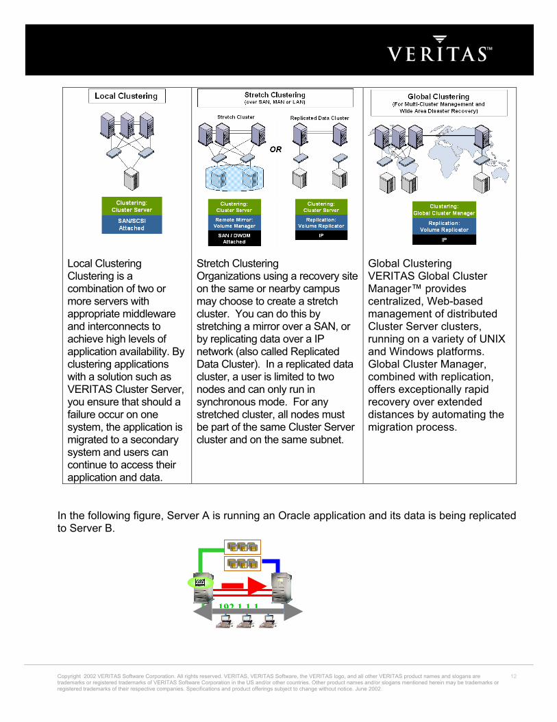
Local Clustering Clustering is a combination of two or more servers with appropriate middleware and interconnects to achieve high levels of application availability. By clustering applications with a solution such as VERITAS Cluster Server, you ensure that should a failure occur on one system, the application is migrated to a secondary system and users can continue to access their application and data.
Stretch Clustering Organizations using a recovery site on the same or nearby campus may choose to create a stretch cluster. You can do this by stretching a mirror over a SAN, or by replicating data over a IP network (also called Replicated Data Cluster). In a replicated data cluster, a user is limited to two nodes and can only run in synchronous mode. For any stretched cluster, all nodes must be part of the same Cluster Server cluster and on the same subnet.
Global Clustering VERITAS Global Cluster Manager™ provides centralized, Web-based management of distributed Cluster Server clusters, running on a variety of UNIX and Windows platforms. Global Cluster Manager, combined with replication, offers exceptionally rapid recovery over extended distances by automating the migration process.
In the following figure, Server A is running an Oracle application and its data is being replicated to Server B.
192 1 1 1

When a failure occurs on A side, replication is stopped and the storage on Server B is “promoted” for read/write usage. The Oracle application is now started on Server B. This works well, as the data was kept up to date (hopefully) by the replication package.
192.1.1.1
In the next figure, Server A and Storage A is restored to service. Here is where the issues with replication arise. The data on the storage attached to Server A must be resynchronized with the storage on ServerB. Depending on replication method and amount of data changed on the second storage array, this could take seconds, minutes, hours or even days. During this time, ServerB has no redundancy. So the time required to recover redundancy is increased in a replicated data cluster. The various methods of replication handle the data resynchronization in different ways. For example, host and application based replication require the host server to be up to resynchronize. Array based replication can begin when the storage comes online, but typically with a very large performance penalty to the application still running at the remote side. Regardless of replication method, resynchronization will take some period of time during which the supposed HA application has no redundancy.
For most environments, use of a replicated data cluster rather than a shared data cluster will result in lower overall availability. If this architecture is absolutely required, it is possible to utilize the cluster software to control the underlying replication. Data replication does have a place in High Availability. It is best used to provide site protection, outside the limits of the Storage Area Network. For day-to-day application availability, a local High Availability cluster with shared disks is used. This data is then replicated outside the cluster to another facility to protect against disaster.
Copyright 2002 VERITAS Software Corporation. All rights reserved. VERITAS, VERITAS Software, the VERITAS logo, and all other VERITAS product names and slogans are trademarks or registered trademarks of VERITAS Software Corporation in the US and/or other countries. Other product names and/or slogans mentioned herein may be trademarks or registered trademarks of their respective companies. Specifications and product offerings subject to change without notice. June 2002.
13
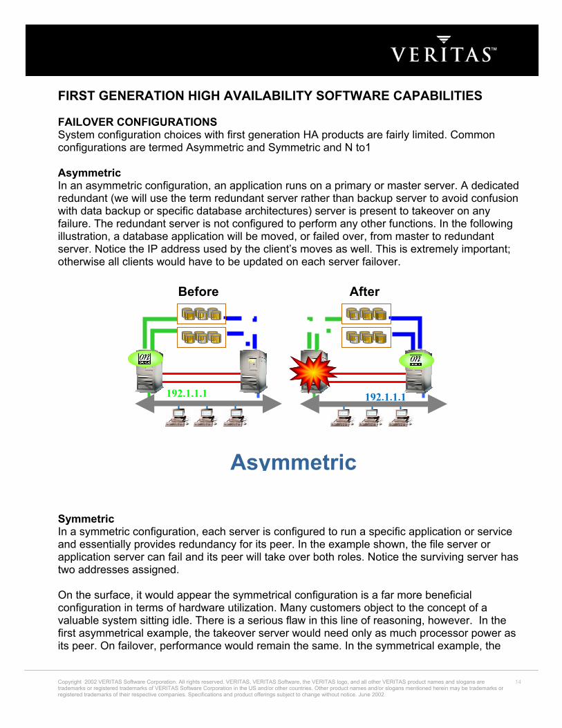
FIRST GENERATION HIGH AVAILABILITY SOFTWARE CAPABILITIES FAILOVER CONFIGURATIONS System configuration choices with first generation HA products are fairly limited. Common configurations are termed Asymmetric and Symmetric and N to1 Asymmetric In an asymmetric configuration, an application runs on a primary or master server. A dedicated redundant (we will use the term redundant server rather than backup server to avoid confusion with data backup or specific database architectures) server is present to takeover on any failure. The redundant server is not configured to perform any other functions. In the following illustration, a database application will be moved, or failed over, from master to redundant server. Notice the IP address used by the client’s moves as well. This is extremely important; otherwise all clients would have to be updated on each server failover.
Before
192.1.1.1
After
192.1.1.1
Asymmetric Symmetric In a symmetric configuration, each server is configured to run a specific application or service and essentially provides redundancy for its peer. In the example shown, the file server or application server can fail and its peer will take over both roles. Notice the surviving server has two addresses assigned. On the surface, it would appear the symmetrical configuration is a far more beneficial configuration in terms of hardware utilization. Many customers object to the concept of a valuable system sitting idle. There is a serious flaw in this line of reasoning, however. In the first asymmetrical example, the takeover server would need only as much processor power as its peer. On failover, performance would remain the same. In the symmetrical example, the
Copyright 2002 VERITAS Software Corporation. All rights reserved. VERITAS, VERITAS Software, the VERITAS logo, and all other VERITAS product names and slogans are trademarks or registered trademarks of VERITAS Software Corporation in the US and/or other countries. Other product names and/or slogans mentioned herein may be trademarks or registered trademarks of their respective companies. Specifications and product offerings subject to change without notice. June 2002.
14

takeover server would need sufficient processor power to not only run the existing application, but also enough for the new application it takes over. To put it another way, if a single application needs one processor to run properly, an asymmetric configuration would need two single processor systems. To run identical applications on each server, a symmetrical config would require two dual processor systems. Further difficulties can arise in symmetrical configurations when multiple applications running on the same system do not co-exist well. Some applications work perfectly well with multiple copies started on the same system, while some will fail. Even more difficult may be having two different applications, with vastly different I/O and memory requirements run on the same system. All in all, many symmetrical configurations will run fine. It is a matter of thorough testing to uncover any difficulties.
Before After
192.1.1.2 192.1.1.1192.1.1.2192.1.1.1
Symmetric N to 1 N to 1 failover is a way to reduce hardware redundancy cost and still provide a potential dedicated spare in a cluster. In the discussion above, the concepts of asymmetric and symmetric failover were discussed. Asymmetric is the cleanest, as there is no performance penalty and no issues with multiple applications running on the same system. The problem is a 100% cost of redundancy at the server level.
Copyright 2002 VERITAS Software Corporation. All rights reserved. VERITAS, VERITAS Software, the VERITAS logo, and all other VERITAS product names and slogans are trademarks or registered trademarks of VERITAS Software Corporation in the US and/or other countries. Other product names and/or slogans mentioned herein may be trademarks or registered trademarks of their respective companies. Specifications and product offerings subject to change without notice. June 2002.
15
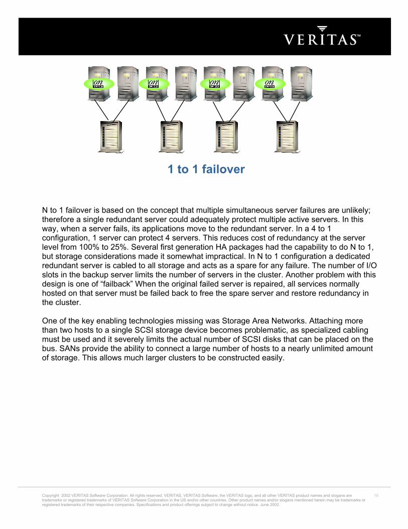
1 to 1 failover N to 1 failover is based on the concept that multiple simultaneous server failures are unlikely; therefore a single redundant server could adequately protect multiple active servers. In this way, when a server fails, its applications move to the redundant server. In a 4 to 1 configuration, 1 server can protect 4 servers. This reduces cost of redundancy at the server level from 100% to 25%. Several first generation HA packages had the capability to do N to 1, but storage considerations made it somewhat impractical. In N to 1 configuration a dedicated redundant server is cabled to all storage and acts as a spare for any failure. The number of I/O slots in the backup server limits the number of servers in the cluster. Another problem with this design is one of “failback” When the original failed server is repaired, all services normally hosted on that server must be failed back to free the spare server and restore redundancy in the cluster. One of the key enabling technologies missing was Storage Area Networks. Attaching more than two hosts to a single SCSI storage device becomes problematic, as specialized cabling must be used and it severely limits the actual number of SCSI disks that can be placed on the bus. SANs provide the ability to connect a large number of hosts to a nearly unlimited amount of storage. This allows much larger clusters to be constructed easily.
Copyright 2002 VERITAS Software Corporation. All rights reserved. VERITAS, VERITAS Software, the VERITAS logo, and all other VERITAS product names and slogans are trademarks or registered trademarks of VERITAS Software Corporation in the US and/or other countries. Other product names and/or slogans mentioned herein may be trademarks or registered trademarks of their respective companies. Specifications and product offerings subject to change without notice. June 2002.
16

N to 1 failover FAILOVER GRANULARITY Another important limitation of first generation FMS systems is failover granularity. This refers to what must failover on the event of any problems. First generation systems had failover granularity equal to a server. This means on failure of any HA application on a system, all applications would fail to a second system. This fact severely limited scalability of any given server. For example, running multiple production Oracle instances on a single system is problematic, as the failure of any instance will cause an outage of all instances on the system while all applications are migrated to another server. FIRST GENERATION HA SUMMARY First generation HA packages provided the beginning of Application Availability Management. The lack of configuration possibilities and large failover granularity made fully realizing this potential difficult. Companies today are faced with the prospect of large-scale server consolidation and increased demands for availability. Second generation HA products are designed to address these concerns. SECOND GENERATION HIGH AVAILABILITY SOFTWARE CHANGES IN STORAGE ARCHITECTURE Scalability is the first major benefit gained from second generation HA software. Most second generation HA packages can scale to 8 or more nodes. As mentioned above, SAN technology has made much larger clusters possible. Software vendors have taken advantage of this capability and designed cluster packages that scale to 8, 16 or even 32 nodes. VERITAS Cluster Server is the only available FMS package with tested, supported 32-node capability.
Copyright 2002 VERITAS Software Corporation. All rights reserved. VERITAS, VERITAS Software, the VERITAS logo, and all other VERITAS product names and slogans are trademarks or registered trademarks of VERITAS Software Corporation in the US and/or other countries. Other product names and/or slogans mentioned herein may be trademarks or registered trademarks of their respective companies. Specifications and product offerings subject to change without notice. June 2002.
17

Service Groups The second distinguishing feature of a second generation HA package is the concept of resource groups or service groups. As customers move into larger “enterprise class” servers, it is rare that the entire server will be dedicated to a single application service. Configuring multiple domains on an enterprise server partially alleviates the problem, however multiple applications may still run within each domain. Failures that affect a single application service, such as a software failure or hang, should not necessarily affect other application services that may reside on the same physical host or domain. If they do, then downtime may be unnecessarily incurred for the other application services. An application service is the service the end user perceives when accessing a particular network address. An application service is typically composed of multiple resources, some hardware and some software based, all cooperating together to produce a single service. For example, a database service may be composed of a logical network (IP) addresses, the DBMS software, underlying file systems, logical volumes and a set of physical disks being managed by the volume manager. If this service, typically called a Service Group, needs to be migrated to another node for recovery purposes, all of its resources must migrate together to re-create the service on another node, without affecting other Service Groups. A single large node may host any number of service groups, each providing a discrete service to networked clients. If multiple service groups are running on a single node, then they must be monitored and managed independently. Independent management allows a service group to be automatically recovered or manually idled (e.g. for administrative or maintenance reasons) without necessarily impacting any of the other service groups running on a node. Of course, if the entire server crashes (as opposed to just a software failure or hang), then all the service groups on that node must be recovered elsewhere. At the most basic level, the fault management process includes monitoring a service group and, when a failure is detected, restarting that service group automatically. This could mean restarting it locally or moving it to another node and then restarting it, as determined by the type of failure incurred. In the case of local restart in response to a fault, the entire service group does not necessarily need to be restarted; perhaps just a single resource within that group may need to be restarted to restore the application service. Given that service groups can be independently manipulated, a failed node’s workload can be load balanced across remaining cluster nodes, and potentially failed over successive times (due to consecutive failures over time) without manual intervention, as shown below in N to N configuration ADVANCED FAILOVER CONFIGURATIONS The advent of Storage Area Networks, combined with second-generation High Availability products such as the VERITAS Cluster Server has enabled several new and useful failover configurations. N + 1
Copyright 2002 VERITAS Software Corporation. All rights reserved. VERITAS, VERITAS Software, the VERITAS logo, and all other VERITAS product names and slogans are trademarks or registered trademarks of VERITAS Software Corporation in the US and/or other countries. Other product names and/or slogans mentioned herein may be trademarks or registered trademarks of their respective companies. Specifications and product offerings subject to change without notice. June 2002.
18

The capabilities brought about by Storage Area Networks allow not only much larger clusters, but even more importantly, for multiple servers to be connected to the same storage. What this allows is removing the concept of a dedicated redundant server from the equation. Rather than N to 1 configurations, we can now have “N + 1”. In advanced N +1 configurations, an extra server in the cluster is simply spare horsepower. When a server fails, the application restarts on the “spare” server. When the original server is repaired, it becomes the spare server. In this configuration, there is no longer a need for a second application outage to put the service group back on the “primary node”. Any server can provide redundancy for any other server. This allows for 8 or greater node clusters with 1 spare server. Cascading failover is also possible to tolerate multiple server outages. This will require very thorough testing and planning, as this brings back all the difficulties discussed in Symmetrical Failover.
N + 1 Failover N to M N-to-M clustering is at the core of highly available architecture supporting multiple applications. N-to-N refers to multiple Service Groups running on multiple servers, with each Service Group capable of being failed over to different servers in the cluster. For example, imagine a 4-node cluster, with each node supporting 3 critical database instances. On failure of any node, each of the three instances is started on a different node, ensuring on node does not get overloaded. This is a logical evolution of N + 1, where there is not a need for a “standby system” but rather “standby capacity” in the cluster. Cascading failure is also possible in this configuration. The side benefit to running in an N to M configuration likely means application interoperability considerations have already been tested and cascading failover is then simply a matter of determining additional load each individual server can handle.
Copyright 2002 VERITAS Software Corporation. All rights reserved. VERITAS, VERITAS Software, the VERITAS logo, and all other VERITAS product names and slogans are trademarks or registered trademarks of VERITAS Software Corporation in the US and/or other countries. Other product names and/or slogans mentioned herein may be trademarks or registered trademarks of their respective companies. Specifications and product offerings subject to change without notice. June 2002.
19

PROACTIVE CLUSTER USAGE Online Maintenance In a modern information processing system, users expect access to the system 24 hours a day. This means there is no time for planned maintenance. Planned downtime as well as unplanned downtime is simply downtime from a business perspective. Application clustering allows proactive application reconfiguration to support planned downtime. For example, adding additional memory and processors to a database server. The operator has several methods available to perform the upgrade. The simplest will be to upgrade a system where the database is not currently running, move the database to the upgraded machine then upgrade the original database server. The decision to support true N + 1 clustering, where any system can be the host for any application makes this task very easy. Cluster node additions Another capability that modern day clustering brings (on some commercial available packages, including VCS) is the capability to add cluster nodes while the cluster is running. This allows a number of proactive maintenance capabilities. Imagine the scenario from the last example. The database server needed upgrading. With the ability to add nodes on the fly, instead of upgrading an in-place system, a newer more powerful system can be rolled in, connected to storage and cluster interconnect networks and quickly come up as a cluster member. The critical database could then be moved once to its newer, more powerful server. Managing Temporary Performance Needs
Copyright 2002 VERITAS Software Corporation. All rights reserved. VERITAS, VERITAS Software, the VERITAS logo, and all other VERITAS product names and slogans are trademarks or registered trademarks of VERITAS Software Corporation in the US and/or other countries. Other product names and/or slogans mentioned herein may be trademarks or registered trademarks of their respective companies. Specifications and product offerings subject to change without notice. June 2002.
20

Managing temporary performance needs builds on the capabilities addressed in online cluster node additions. Imagine a company that processes online orders for a catalog business. During the month before Christmas, orders, and therefore database utilization increases by 10 times. Now a database that normally runs on a 4 CPU system needs a 16 or 24 CPU system just to stay afloat. So, during that month, a system could be borrowed from development or some other company area and used to support sales operations. The beauty of clustering is the ease with which an application can be moved from one server to another, therefore allowing planning for peak performance needs. Server Consolidation As open systems have proliferated, companies are faced with a challenge to regain manageability of vast numbers of servers with less manpower and achieve increased utilization of compute resources. Many companies have seen 4 and 8 CPU systems spread everywhere, each running a specific task, and often time used at 10% or less. Server centralization is an effort to use the minimum number of enterprise class servers as possible, by running all at 80 to 90%. In order to achieve higher utilization levels, multiple applications will have to run on each system. Controlling a complex environment and keeping applications available is the perfect place for an advanced second generation HA product. Horizontal Scaling Horizontal scaling means adding processing power by adding additional commodity systems as necessary, rather than buying larger and larger individual servers. This is one of the more sought after capabilities in a cluster in current data center environments. The concept of horizontal scaling is very elegant. Each layer of a data center, such as web servers, application servers and database servers would provide multiple “instances” of a given application. Other applications or systems requiring the service of a given application would be “load balanced” across the running instances of an application. If a given server fails, the remaining servers running an instance of the application take over. If more processing power is needed, more servers are added. While the concept of horizontal scaling sounds very promising, actual implementation must follow strict guidelines to prevent data corruption. Most common applications were not designed to function properly with multiple copies of the application accessing the same data. A good example is a standard Oracle database versus the Oracle Parallel Server. A standard Oracle database expects complete ownership of all underlying data structures. The database keeps in-memory copies of data present in disk storage. Since the database expects complete ownership, it has no reason to check the on disk copy for consistency prior to overwriting sections of disk storage. If multiple Oracle instances were started with the same actual database, each would have no idea the other was present and overwrite blocks of data. The Oracle Parallel Server is designed to overcome this problem by implementing a distributed lock manager to keep multiple instances in synchronization with regards to disk storage. In order for an application to be utilized in a horizontal scaling or parallel processing model, it must meet one of three possible storage models. The first is utilizing no shared storage. For example, a series of stand alone web servers, each serving content from a local HTML
Copyright 2002 VERITAS Software Corporation. All rights reserved. VERITAS, VERITAS Software, the VERITAS logo, and all other VERITAS product names and slogans are trademarks or registered trademarks of VERITAS Software Corporation in the US and/or other countries. Other product names and/or slogans mentioned herein may be trademarks or registered trademarks of their respective companies. Specifications and product offerings subject to change without notice. June 2002.
21

documents directory. The second model is one where the application utilizes the underlying file system and performs locking to prevent data corruption. In this case, an application is designed to tolerate multiple copies running accessing the same storage. The application must also define a method to tolerate other instances modifying data while it is processing. For example, what happens if a web application is accepting an online transaction while another system updates the sales price of an item? The last storage model is one where the application handles all locking and consistency issues within the application itself. This is the model followed by Oracle Parallel Server. With the advent of SAN technology, many customers are looking to leverage the I/O bandwidth of the SAN to provide data access for parallel applications. VERITAS has recently shipped the SANPoint Foundation Suite/HA (SPFS/HA). SPFS/HA is a solution package including VCS, and cluster capable versions of the VERITAS Volume Manager and VERITAS File System. The Cluster Volume Manager (CVM) and Cluster File System (CFS) provide a base for developing horizontally scaled applications. Horizontal scaling will become much more commonplace in the data centers as application vendors begin to utilize the power of Storage Area Networks and technology such as the VERITAS Cluster File System and Cluster Volume Manager. WHY VCS? VERITAS Cluster Server is a state of the art, multi-platform High Availability package currently shipping on Sun Solaris, HP/UX and Windows NT 4 and planned on Win2000, AIX and Linux. Key features of VERITAS Cluster Server include:
• Extremely scalable (up to 32 nodes in a cluster). This allows building larger clusters to support increasingly complex applications, as well as reducing total number of “spare” systems needed.
• Supports multiple environments. Windows NT, Solaris and HP/UX are supported today. Support for additional operating systems is planned. (Individual clusters must all be comprised of the same operating system family. Clusters of multiple OS types can all be managed from the Cluster Manager console).
• Because Cluster Server is a multi-platform solution, administrators only need to learn one clustering technology to support multiple environments. A single group of administrators can become experts on “High Availability Administration”
• Provides a new approach to managing large server clusters. Through its Java-based graphical management interface, administrators can manage large clusters automatically or manually, and migrate applications and services among them.
• Supports all major third-party storage providers and works in SCSI, NAS and SAN environments.
• Provides flexible failover possibilities. 1 to 1, any to 1, any to any, and 1 to any failovers. • Dynamic choice of failover node. Target node can be chosen based on system load,
number of Service Groups online (Round Robin) or defined priority. • Support for parallel and failover service groups
Copyright 2002 VERITAS Software Corporation. All rights reserved. VERITAS, VERITAS Software, the VERITAS logo, and all other VERITAS product names and slogans are trademarks or registered trademarks of VERITAS Software Corporation in the US and/or other countries. Other product names and/or slogans mentioned herein may be trademarks or registered trademarks of their respective companies. Specifications and product offerings subject to change without notice. June 2002.
22

• Integrates seamlessly with other VERITAS products to increase availability, reliability,
and performance. • Provides a simple method to develop support for new applications via “Agents”. • VCS Technology Concepts
At first glance, VCS seems to be a very complex package. By breaking the technology into understandable blocks, it can be explained in a much simpler fashion. The following section will describe each major building block in a VCS configuration. Understanding each of these items as well as interaction with others is key to understanding VCS. The primary items to discuss include the following:
• Clusters • Resources and resource types • Agents • Agent Classifications • Service Groups • Resource Dependencies • Heartbeat
CLUSTERS A single VCS cluster consists of multiple systems connected in various combinations to shared storage devices. VCS monitors and controls applications running in the cluster, and can restart applications in response to a variety of hardware or software faults. A cluster is defined as all systems with the same cluster-ID and connected via a set of redundant heartbeat networks. (See the VCS Daemons and Communications white paper for a detailed discussion on cluster ID and heartbeat networks). Clusters can have from 1 to 32 member systems, or “nodes”. All nodes in the cluster are constantly aware of the status of all resources on all other nodes. Applications can be configured to run on specific nodes in the cluster. Storage is configured to provide access to shared application data for those systems hosting the application. In that respect, the actual storage connectivity will determine where applications can be run. Nodes sharing access to storage will be “eligible” to run an application. Nodes without common storage cannot failover an application that stores data to disk. Within a single VCS cluster, all member nodes must run the same operating system family. For example, a Solaris cluster would consist of entirely Solaris nodes, likewise with HP/UX and NT clusters. Multiple clusters can all be managed from one central console with the Cluster Server Cluster Manager. The Cluster Manager allows an administrator to log in and manage a virtually unlimited number of NT and Unix VCS clusters, using one common GUI and command line interface. The common GUI and command line interface is the most powerful feature of VCS. RESOURCES AND RESOURCE TYPES Resources are hardware or software entities, such as disks, network interface cards (NICs), IP addresses, applications, and databases, which are controlled by VCS. Controlling a resource
Copyright 2002 VERITAS Software Corporation. All rights reserved. VERITAS, VERITAS Software, the VERITAS logo, and all other VERITAS product names and slogans are trademarks or registered trademarks of VERITAS Software Corporation in the US and/or other countries. Other product names and/or slogans mentioned herein may be trademarks or registered trademarks of their respective companies. Specifications and product offerings subject to change without notice. June 2002.
23

means bringing it online (starting), taking it offline (stopping) as well as monitoring the health or status of the resource. Resources are classified according to types, and multiple resources can be of a single type; for example, two disk resources are both classified as type Disk. How VCS starts and stops a resource is specific to the resource type. For example, mounting starts a file system resource, and an IP resource is started by configuring the IP address on a network interface card. Monitoring a resource means testing it to determine if it is online or offline. How VCS monitors a resource is also specific to the resource type. For example, a file system resource tests as online if mounted, and an IP address tests as online if configured. Each resource is identified by a name that is unique among all resources in the cluster. VCS includes a set of predefined resources types. For each resource type, VCS has a corresponding agent. The agent provides the resource type specific logic to control resources. AGENTS The actions required to bring a resource online or take it offline differ significantly for different types of resources. Bringing a disk group online, for example, requires importing the Disk Group, whereas bringing an Oracle database online would require starting the database manager process and issuing the appropriate startup command(s) to it. From the cluster engine’s point of view the same result is achieved—making the resource available. The actions performed are quite different, however. VCS handles this functional disparity between different types of resources in a particularly elegant way, which also makes it simple for application and hardware developers to integrate additional types of resources into the cluster framework. Each type of resource supported in a cluster is associated with an agent. An agent is an installed program designed to control a particular resource type. For example, for VCS to bring an Oracle resource online it does not need to understand Oracle; it simply passes the online command to the Oracle Agent. The Oracle Agent knows to call the server manager and issue the appropriate startup command. Since the structure of cluster resource agents is straightforward, it is relatively easy to develop agents as additional cluster resource types are identified.
SQL Agent
Oracle Agent
??
Custom Agent
VERITAS Cluster Server Engine
Copyright 2002 VERITAS Software Corporation. All rights reserved. VERITAS, VERITAS Software, the VERITAS logo, and all other VERITAS product names and slogans are trademarks or registered trademarks of VERITAS Software Corporation in the US and/or other countries. Other product names and/or slogans mentioned herein may be trademarks or registered trademarks of their respective companies. Specifications and product offerings subject to change without notice. June 2002.
24
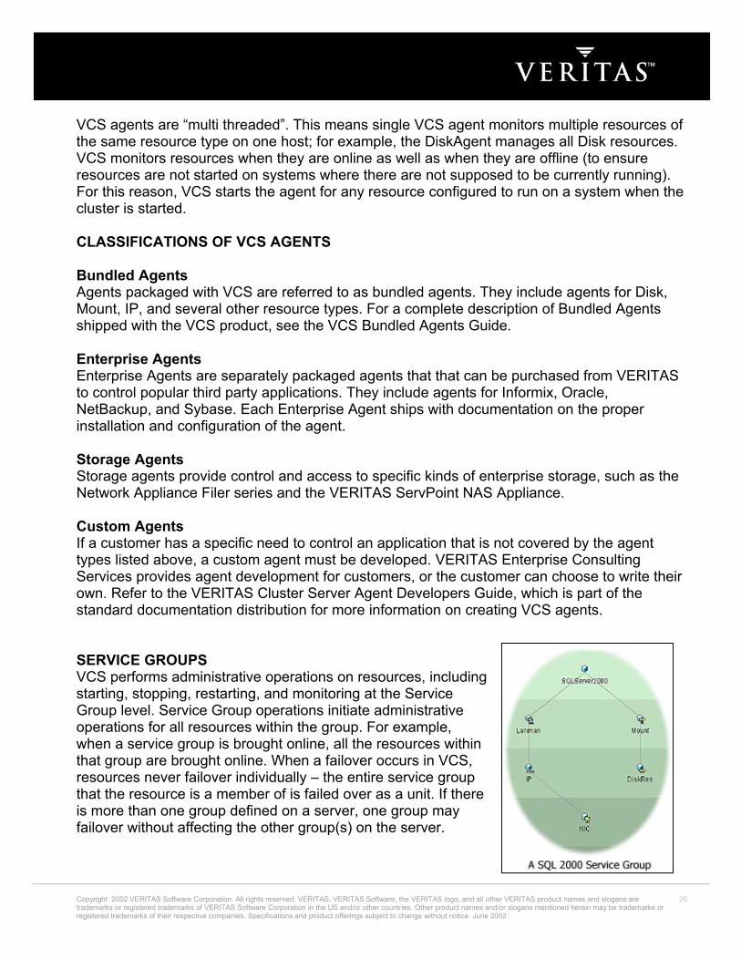
VCS agents are “multi threaded”. This means single VCS agent monitors multiple resources of the same resource type on one host; for example, the DiskAgent manages all Disk resources. VCS monitors resources when they are online as well as when they are offline (to ensure resources are not started on systems where there are not supposed to be currently running). For this reason, VCS starts the agent for any resource configured to run on a system when the cluster is started. CLASSIFICATIONS OF VCS AGENTS Bundled Agents Agents packaged with VCS are referred to as bundled agents. They include agents for Disk, Mount, IP, and several other resource types. For a complete description of Bundled Agents shipped with the VCS product, see the VCS Bundled Agents Guide. Enterprise Agents Enterprise Agents are separately packaged agents that that can be purchased from VERITAS to control popular third party applications. They include agents for Informix, Oracle, NetBackup, and Sybase. Each Enterprise Agent ships with documentation on the proper installation and configuration of the agent. Storage Agents Storage agents provide control and access to specific kinds of enterprise storage, such as the Network Appliance Filer series and the VERITAS ServPoint NAS Appliance. Custom Agents If a customer has a specific need to control an application that is not covered by the agent types listed above, a custom agent must be developed. VERITAS Enterprise Consulting Services provides agent development for customers, or the customer can choose to write their own. Refer to the VERITAS Cluster Server Agent Developers Guide, which is part of the standard documentation distribution for more information on creating VCS agents. SERVICE GROUPS VCS performs administrative operations on resources, including starting, stopping, restarting, and monitoring at the Service Group level. Service Group operations initiate administrative operations for all resources within the group. For example, when a service group is brought online, all the resources within that group are brought online. When a failover occurs in VCS, resources never failover individually – the entire service group that the resource is a member of is failed over as a unit. If there is more than one group defined on a server, one group may failover without affecting the other group(s) on the server.
Copyright 2002 VERITAS Software Corporation. All rights reserved. VERITAS, VERITAS Software, the VERITAS logo, and all other VERITAS product names and slogans are trademarks or registered trademarks of VERITAS Software Corporation in the US and/or other countries. Other product names and/or slogans mentioned herein may be trademarks or registered trademarks of their respective companies. Specifications and product offerings subject to change without notice. June 2002.
25

From a cluster standpoint, there are two significant aspects to this view of an application Service Group as a collection of resources:
• If a Service Group is to run on a particular server, all of the resources it requires must be available to the server.
• The resources comprising a Service Group have interdependencies; that is, some resources (e.g., NIC) must be operational before other resources (e.g., IP address) can be made operational.
One of the most important parts of a service group definition is the concept of resource dependencies. As mentioned above, resource dependencies determine the order specific resources within a Service Group are brought online or offline when the Service Group is brought offline or online. For example, a NIC resource must be online before the IP address can be brought online, and the IP must be online before the network name can be brought online. In the same manner, databases must be stopped before volumes are stopped and volumes stopped before disk groups deported. VCS service groups fall in two categories, depending on whether they can be run on multiple servers simultaneously. Failover Groups A failover group runs on one system in the cluster at a time. Failover groups are used for most application services, such as most databases, messaging servers and any other application not designed to maintain data consistency when multiple copies are started.
ParA paA pacanthat CluVCSThishearesoplaccomcoma sy
Copyrigtrademaregister
Failover is the process by which an application, including its services, network address, data volumes, and hostname moves from a failed node to a healthy node
allel Groups rallel group can run concurrently on more than one system in the cluster at a time. rallel service group is more complex than a failover group. It requires an application that
safely be started on more than one system at a time with no threat of data corruption, or the data being accessed is local to each server.
ster Communications (Heartbeat) uses private network communications between cluster nodes for cluster maintenance. communication takes the form of nodes informing other nodes they are alive, known as rtbeat, and nodes informing all other nodes of actions taking place and the status of all urces on a particular node, known as cluster status. This cluster communication takes e over a private, dedicated network between cluster nodes. VERITAS requires two pletely independent, private networks between all cluster nodes to provide necessary munication path redundancy and allow VCS to discriminate between a network failure and stem failure.
ht 2002 VERITAS Software Corporation. All rights reserved. VERITAS, VERITAS Software, the VERITAS logo, and all other VERITAS product names and slogans are rks or registered trademarks of VERITAS Software Corporation in the US and/or other countries. Other product names and/or slogans mentioned herein may be trademarks or
ed trademarks of their respective companies. Specifications and product offerings subject to change without notice. June 2002.
26

VCS uses a purpose built communication package, comprised of the Low Latency Transport (LLT) and Group Membership/Atomic Broadcast (GAB). These packages function together as a replacement for the IP stack and provide a robust, high-speed communication link between systems without the latency induced by the normal network stack.
Split-Brain Split-brain refers to a state where all communication paths between nodes in a cluster have been lost. When this happens, the cluster nodes can’t determine if a network failure occurred or if the other nodes in the cluster have failed. If they assume node failure, there is a risk that applications will be brought online on more than one node in the cluster and will attempt to access the same shared disk, which could lead to potential data corruption. To prevent this from happening, VERITAS Cluster Server uses SCSI-2 disk reservations. When a disk or collection of disks is brought online using VCS, they are reserved by the system which brought them online and cannot be accessed by other servers in the cluster.
Putting the pieces together How do all these pieces tie together to form a cluster? Understanding how the pieces fit makes the rest of VCS fairly simple. Let’s take a very common example, a two-node cluster serving a single NFS file system to clients. The cluster itself consists of two nodes; connected to shared storage to allow both servers to access the data needed for the file system export. In this example, we are going to configure a single Service Group called NFS_Group that will be failed over between ServerA and ServerB as necessary. The service group, configured as a Failover Group, consists of resources, each one with a different resource type. The resources must be started in a specific order for everything to work. This is described with resource dependencies. Finally, in order to control each specific resource type, VCS will require an agent. The VCS engine, HAD, will read the configuration file and determine what agents are necessary to control the resources in this group (as well as any resources in any other service group configured to run on this system) and start the corresponding VCS Agents. HAD will then determine the order to bring up the resources based on resource dependency statements in the configuration. When it is time to online the service group, VCS will issue online commands to the proper agents in the proper order. The following drawing is a representation of a VCS service group, with the appropriate resources and dependencies for the NFS Group. The method used to display the resource dependencies is identical to the VCS GUI.
Copyright 2002 VERITAS Software Corporation. All rights reserved. VERITAS, VERITAS Software, the VERITAS logo, and all other VERITAS product names and slogans are trademarks or registered trademarks of VERITAS Software Corporation in the US and/or other countries. Other product names and/or slogans mentioned herein may be trademarks or registered trademarks of their respective companies. Specifications and product offerings subject to change without notice. June 2002.
27
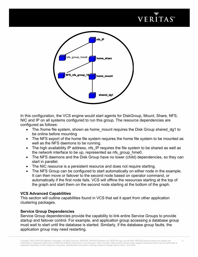
nfs_IP
nfs_group_hme0
home_mount
shared_dg1
home_share
NFS_nfs_group_16
nfs_IPnfs_IP
nfs_group_hme0nfs_group_hme0
home_mounthome_mount
shared_dg1shared_dg1
home_sharehome_share
NFS_nfs_group_16NFS_nfs_group_16
In this configuration, the VCS engine would start agents for DiskGroup, Mount, Share, NFS, NIC and IP on all systems configured to run this group. The resource dependencies are configured as follows:
• The /home file system, shown as home_mount requires the Disk Group shared_dg1 to be online before mounting
• The NFS export of the home file system requires the home file system to be mounted as well as the NFS daemons to be running.
• The high availability IP address, nfs_IP requires the file system to be shared as well as the network interface to be up, represented as nfs_group_hme0.
• The NFS daemons and the Disk Group have no lower (child) dependencies, so they can start in parallel.
• The NIC resource is a persistent resource and does not require starting. • The NFS Group can be configured to start automatically on either node in the example.
It can then move or failover to the second node based on operator command, or automatically if the first node fails. VCS will offline the resources starting at the top of the graph and start them on the second node starting at the bottom of the graph.
VCS Advanced Capabilities This section will outline capabilities found in VCS that set it apart from other application clustering packages. Service Group Dependencies Service Group dependencies provide the capability to link entire Service Groups to provide startup and failover control. For example, and application group accessing a database group must wait to start until the database is started. Similarly, if the database group faults, the application group may need restarting.
Copyright 2002 VERITAS Software Corporation. All rights reserved. VERITAS, VERITAS Software, the VERITAS logo, and all other VERITAS product names and slogans are trademarks or registered trademarks of VERITAS Software Corporation in the US and/or other countries. Other product names and/or slogans mentioned herein may be trademarks or registered trademarks of their respective companies. Specifications and product offerings subject to change without notice. June 2002.
28

VCS has a comprehensive set of Service Group dependency possibilities. VCS provides 4 basic Service Group Dependency types: Online Local, Online Global, Online Remote and Offline Local.
• In an online group dependency, the parent (upper) group must wait for the child (lower) group to be brought online before it can start. For example, to configure an application and a database service as two separate groups, you would specify the application as the parent, and the database service as the child. If the child faults, the parent is stopped and restarted after the child restarts. The online group dependency has 3 forms:
o In a local dependency an instance of the parent group depends on an instance of child group being online on the same system. This is typically used in a database and app service configuration where the application directly connects to the database.
o In a global dependency an instance of parent group depends on an instance of the child group being online on any system. This is typically used in a database environment with a front-end web server connecting via IP.
o In a remote dependency an instance of parent group depends on an instance of the child group being online on any system other than the system on which the parent is online. This configuration is useful where the load of the combined resource groups is too great for a single system
• In an offline local group dependency, the parent group can be started only if the child group is offline on the system, and vice versa. This prevents conflicting applications from running on the same system. For example, you can configure a production application on one system and a test application on another. If the production application fails, the test application will be offlined before the production app starts.
Triggers VCS provides a method for the administrator to carry out specific actions when events occur in the cluster, such as a resource or group fault, or to carry out specific tasks outside the actual service group before it comes online or goes offline. This capability is know as triggers. Triggers provide the capability to extend the functionality of the cluster engine with simple shell scripts, perl or compiled programs. For example, the PreOnline trigger can be used to carry out specific actions such as reconfiguring SAN zoning before bringing up a group. The PostOnline and PostOffline triggers can be used to control applications outside the cluster, such as signalling for a web server restart following a database switchover. Service Group Workload Management Deciding which server should bring up a service group following a failure plays a major role in how well the cluster will function in a server consolidation environment. Lack of a dedicated redundant server or cascading failovers complicates the decisions greatly. For example, if a node in a multi-node cluster is running 10 service groups at time of failure, the administrator may wish all groups to move to an empty redundant server. If this is not available, then the admin may wish the groups to be spread out across remaining servers. How the cluster software determines the “best” takeover node varies between vendors.
Copyright 2002 VERITAS Software Corporation. All rights reserved. VERITAS, VERITAS Software, the VERITAS logo, and all other VERITAS product names and slogans are trademarks or registered trademarks of VERITAS Software Corporation in the US and/or other countries. Other product names and/or slogans mentioned herein may be trademarks or registered trademarks of their respective companies. Specifications and product offerings subject to change without notice. June 2002.
29
Most cluster implementations provide a simple method to determine what node will act as a takeover node after a failure. The order of nodes listed in the configuration sets what node will take over a group. The first node in the system list in a running state will be chosen. This is a very restrictive policy, as it does not scale well in multi-node environments. VERITAS Cluster Server provides three possible failover policies to make managing multiple critical applications simpler. The three primary policies are Priority, Round Robin and Load.
• Priority is the most basic method. The first available running system in the system list is chosen. This is ideal for a simple two-node cluster, or a small cluster with a very small number of Service Groups.
• RoundRobin chooses the system running the least number of Service Groups as a failover target. This is ideal for larger clusters running a large number of Service Groups of essentially the same server load characteristics (for example similar databases or applications).
• Load is the most flexile and powerful policy. It provides the framework for true server consolidation at the data center level in large clusters. In large clusters, with 10’s of nodes and potentially 100’s of applications, the cluster software must be able to decide the best possible system for failover. Load policy is made of two components, System Limits and Group Prerequisites.
• System Limits set a fixed capacity to servers and a fixed demand for service groups. For example, a Sun 6500 is set to a capacity of 400 and a Sun 4500 to 200. A database may have a determined load of 150. On failover, the server in the cluster with the highest remaining capacity will be chosen. When this group starts coming online, the 150 load is subtracted from the server’s remaining capacity. The next Service Group will re-evaluate the remaining capacity of all servers and choose the best candidate.
• The actual load on a server can also be calculated in real-time by an outside application and provide to VCS through a simple command line interface.
• Service Group prerequisites add additional capability to the load policy. The user can set a list of finite resources available on a server, such as shared memory segments, semaphores and others. Each Service group is then assigned a set of prerequisites. For example, a database may need 3 shared memory segments and 10 semaphores. VCS load policy will first determine a subset of all systems that meet these criteria and then choose the lowest loaded system from this set. In this way, an unloaded system that does not meet all the prerequisites of a group will not be chosen.
System Zones SystemZones provide a sub set of systems to use in an initial failover decision. A ServiceGroup will try to stay within its zone before choosing a host in another zone. For example, imagine a typical 3-tier application infrastructure with web servers, application servers and database servers. The application and database servers are configured in a single cluster. Using SystemZones means a ServiceGroup in the application zone to try to fail to another application zone server if it is available. If not, it would then fail to the database zone based on load and limits. In this configuration, excess capacity and limits available on the database backend would essentially be kept in reserve for the larger load of a database failover, while application servers would handle the load of any groups in the application zone.
Copyright 2002 VERITAS Software Corporation. All rights reserved. VERITAS, VERITAS Software, the VERITAS logo, and all other VERITAS product names and slogans are trademarks or registered trademarks of VERITAS Software Corporation in the US and/or other countries. Other product names and/or slogans mentioned herein may be trademarks or registered trademarks of their respective companies. Specifications and product offerings subject to change without notice. June 2002.
30

During a cascading failure, excess capacity in the cluster is still available to any ServiceGroup. The SystemZones feature allows fine tuning application failover decisions, yet still retains the flexibility to fail anywhere in the cluster if necessary. Loadwarning Overload warning provides the final piece of the load policy. When a server sustains a pre-determined load level (static or dynamically determined) the Loadwarning trigger is initiated. (See Triggers for a full description of Event Management with Triggers). The overload trigger is a user defined script or application designed to carry out the proper actions. Sample scripts detail simple operator warning on overload as well as a method to move or shutdown groups based on user defined priority values. For example, if load on a server running a business critical database reaches and stays above a user defined threshold, operators will be immediately notified. The Loadwarning trigger could then scan the system for any service groups with a lower priority than the database (such as an internal HR app) and move the app to a lesser-loaded system or even shut the app down. The key here is the framework is completely flexible. The installer or user is free to implement any overload management scheme desired. Notification VCS 2.0 provides full SNMP MIB support and a highly available SNMP/SMTP notifier. Features include:
• Configurable Recipient List • Configurable Severity Levels • Configurable number of SNMP/SMTP Servers • SNMP Notification
o Support for HP OpenView, Novell ManageWise, IBM Tivoli • SMTP Notification
o Mail to specified recipients based on type/location of failure User Privileges VCS 2.0 extends administrative capabilities by allowing multiple classes of cluster operators. Administrative privileges can be assigned at the cluster and group levels. Privileges can be granted for guest, operator and administrator levels. For example, a user can have complete control to modify and operate specific service group (group administrator), yet only be allowed to view the remainder of the cluster configuration (cluster guest). Granting operator privileges only allows starting and stopping service groups. For example, a database administrator can start and stop a database service group, but not change its configuration. VCS IN THE DATA CENTER The decision to deploy VCS in the data center is straightforward. VCS provides a robust, scalable, multi-platform solution to application availability. However, simply deploying VCS does not solve all problems. In order to provide maximum availability to a critical application, a cluster solution should only be deployed on top of the most reliable underlying systems.
Copyright 2002 VERITAS Software Corporation. All rights reserved. VERITAS, VERITAS Software, the VERITAS logo, and all other VERITAS product names and slogans are trademarks or registered trademarks of VERITAS Software Corporation in the US and/or other countries. Other product names and/or slogans mentioned herein may be trademarks or registered trademarks of their respective companies. Specifications and product offerings subject to change without notice. June 2002.
31

Reducing availability of any component in a cluster reduces the overall availability of the cluster. In their excellent book on High Availability, “Blueprints for High Availability: Designing Resilient Distributed Systems” (John Wiley and Sons, 2000), Evan Marcus and Hal Stern make the very important point that “High Availability cannot be achieved by merely installing failover software and walking away. It requires a layered approach.” Building a High Availability environment is not trivial. To actually achieve the highest levels of availability, every component of the information processing architecture must be examined. HIGH AVAILABILITY EVERYWHERE VCS provides more than just application failover, it provides an application control infrastructure. Complex applications can be managed easily within the VCS framework. Applications such as web servers and middleware servers in a load-balancing configuration can benefit from VCS even if failover is not necessary. In load-balancing configurations, VCS can provide application monitoring and local restart capability to increase availability of standalone systems. Placing these type applications under VCS control also allows control across layers of processing in a data center, such as restarting a middleware application when a database application is started. For architectures with differing operating systems in various areas of the data center, such as NT web servers and Unix middleware and database, VERITAS offers the Global Cluster Manager. GCM is a cluster management tool providing a high level view of an entire data center as well as “cross cluster event correlation”. This capability allows an event in one cluster to trigger an action in another cluster. Global Cluster Manager also provides the framework for wide area failover. GCM can detect problems with a service group, cluster or entire site and take a predefined action. This will typically require changing the replication configuration between sites to make the secondary site read/write and starting required applications at the secondary site. The GCM package will then update DNS pointers to direct users to the secondary site. SUMMARY It is a challenge to ensure the high availability of applications and data in today’s rapidly growing Windows data center environments. Many factors can cause downtime – planned downtime to perform system maintenance and necessary upgrades, as well as unexpected faults with software and hardware. VERITAS delivers a solution stack of fully tested, integrated products, which provide every level of availability, that your business may require, from local tape backup to wide area disaster recovery. VERITAS Cluster Server, market leader in clustering and Network Magazine’s “Product of the Year 2001”, provides enterprise level high availability in a scalable, easy-to-manage and integrated solution for medium to global-sized organizations. To learn more about VERITAS Products for Windows, visit http://www.veritas.com.
Copyright 2002 VERITAS Software Corporation. All rights reserved. VERITAS, VERITAS Software, the VERITAS logo, and all other VERITAS product names and slogans are trademarks or registered trademarks of VERITAS Software Corporation in the US and/or other countries. Other product names and/or slogans mentioned herein may be trademarks or registered trademarks of their respective companies. Specifications and product offerings subject to change without notice. June 2002.
32