managing risk associated with erosion-driven slope … · 2016-03-30 · engineering structures...
TRANSCRIPT

191
Managing risk associated with erosion-driven slope instabilities with ground
support & surface water management in a high rainfall environment at Ok Tedi
Copper-Gold Mine
Bar N 1, Kuira P
2, Semi J
2
1 Senior Advisor – Geotechnical Design, Ok Tedi Mining Limited, Tabubil, Papua New Guinea
2 Geotechnical Engineer, Ok Tedi Mining Limited, Tabubil, Papua New Guinea
Abstract
Ok Tedi Copper-Gold Mine is a large open pit mine in the Western Province of Papua New Guinea that typically receives in excess of 10m annual rainfall.
Surface water runoff during high intensity rain events initiates localized erosion on benches and bench faces on nearly a daily basis. In zones of friable and highly fractured rock, the erosion quickly proceeds to the undercutting geological structures; enabling small-scale block toppling as well as planar and wedge sliding mechanisms to occur. When uncontrolled, the problem progressively worsens leading to the development of large chasms along major geological structures on pit slopes. Chasms of up to 180m high and 220m wide have developed at Ok Tedi as illustrated in Figure 1.
With high inter-ramp slopes and the progressive loss of bench containment capacity, the chasms forming on pit slopes present a number of short-term risks to the operation including rock falls, debris flows and temporary loss of access to the ore body. Continued growth of the chasms has also had the potential to erode across and permanently destroy main haul roads.
Effectively managing surface water runoff has been the most successful method of preventing the development of chasms. However, in some areas this has either not been possible or the rock was so friable that it had a limited success. As a result, numerous ground support methods including mesh & shotcrete, grouted piles, gabion baskets and lined drainage systems have been trialed in critical areas to reduce chasm enlargement. Safety is being managed through the use of real time slope monitoring systems including automatic total stations and slope stability radar.
Figure 1 – Photograph of Chasms on West Wall of Ok Tedi Mine with Rialto Towers, Melbourne for scale

192
1. Introduction
In the context of this technical paper, a major chasm is not a void due to a single event rock wedge slide from the slope face. Rather, a chasm is the end product of the enlargement of an initial minute starter void by progressive attrition of the rock mass around the starter void.
Why is a chasm an example of management of complex projects relevant to this conference‟s theme? Hopefully, this is answered below.
In an ideal world, all chasms could be prevented from developing on mine pit slopes. But the real world of mining is not an ideal process for the following reasons.
1. Mining would not proceed unless the activity was economically profitable;
2. To minimize the orebody to waste rock strip ratio and improve profitability, overall open pit
slopes are excavated as steep as safely possible;
3. Mine open pits are relatively short-term (often 5-25 years) excavations and not long-term civil
engineering structures (50-100+ years) in rock. Lower geotechnical factors of safely (FOS) are
acceptable in mining (FOS ~ 1.2 to 1.3) than in civil engineering (1.5 to 2.0);
4. From geometry of the pit excavation and need to construct haul roads on the slope face to
access the orebody on the pit floor, inter-ramp slopes and individual bench faces are
excavated steeper than overall slopes. Without a systematic pattern of ground support (cable-
anchors, mesh and shotcrete), some instability of inter-ramp and individual benches is
unavoidable and tolerated; as long as those instabilities are predicted, controlled and do not
impact pit safety. For example, minor instability along 30% of cumulative bench crest length is
expected in most open pits.
5. Slope face instabilities occur in areas of adversely orientated geological structures and/or
intensely sheared and inherently low strength rock mass and almost soil-like materials. Such
failures are promoted by high groundwater pressures in the slope, establishment of perched
saturated water tables immediately behind the slope face due to infiltration during intense and
prolonged rainfall events, poor control of surface water runoff along slope faces, poor
production blasting practices, and poor final slope face excavation practices.
6. From a geotechnical perspective, open pit rock slopes are designed to minimize risk of
geological defect and low-strength material controlled failures. The design process is
statistical because it is based on geological defect and rock mass strength models
established by point-sampling (boreholes) of the ground at a finite number of widely-spaced
locations. The statistical models are then extrapolated to the rest of the proposed pit
excavation. The geotechnically designed steepness of overall, inter-ramp and bench slopes
is appropriate to the strength parameters and the prevailing groundwater conditions or the
drawdown achievable during the operating mine life; with allowance also made for earthquake
events and blasting disturbance of the slope rock mass.
7. The existing Ok Tedi Pit slopes were designed to avoid major wedge failures and were
significantly flattened where they were mined through low strength rock mass materials to
avoid slip-circle failure modes. Slope dewatering measures are being implemented as the
slope is mined down to its target depth.
8. In hindsight, most major chasms at Ok Tedi had developed in low strength rock mass
materials and propagated along traces of major faults in the slope.
9. It is fair to state that most major faults at Ok Tedi are not especially conspicuous as being
significant or easily distinguished from other nearby minor geological defects. In fact, the true
length of many major faults had only become apparent after some ground displacement and
surface-water runoff erosion had occurred along them.
10. In view of the point immediately above, it is often difficult to predict where chasm development
will definitely initiate and where initially minor, surface water runoff caused slope face erosion
might continue to propagate into a major void.

193
11. If the future location of major chasms could be confidently predicted well in advance, then
preventative measures (i.e., mesh and shotcrete slope face protection, slope face dewatering
and better control of surface water runoff) could be specifically targeted to prevent the initiation
of these voids. However, without exact geotechnical prediction, past mine management has
been justifiably reluctant to invest many millions of dollars on preventative ground and water
control measures that might or might not be eventually required. This statement does not
excuse all less than optimum practices with respect to control of surface water runoff on Ok
Tedi mine slopes.
12. Once the chasms had initiated, Ok Tedi had invested considerable remedial effort and
expense in its attempts to control the progressive enlargement of the chasms.
13. The remedial effort includes sophisticated ground control monitoring, establishment of new
access ramps down the slope face, construction of new drains for diversion of surface water
runoff away from the chasm footprint, ground stabilisation chasm crest and toe and slope face
dewatering. All of this remedial activity had to be accommodated within the daily framework of
other pit mining activity and completed in often extremely poor weather conditions.
14. Whatever remedial measures are adopted will only be short term because the west wall
cutback will mine out all of the chasms presented in this paper within 4 to 5 years.
Figure 2 – Location of Chasms and Monitoring Instrumentation at Ok Tedi Mine (left); Location of Ok Tedi Mine in Western Province (right)

194
2. Location and Climate
The Ok Tedi Copper-Gold Mine is situated at an altitude of 2000m above sea level in the Star Mountains of the Western Province of Papua New Guinea. The location of the mine is shown in Figure 2. Mining at the original Mt Fubilan deposit began in the 1980‟s with gold and copper production commencing in 1984 and 1987, respectively (England, 1993). To date, the mine had produced approximately 4.6 million tonnes of copper, 14 million ounces of gold and 29 million ounces of silver.
Mt Fubilan (now Fubilan Pit) had a pre-mining elevation of 2055m and has since been mined vertically down over 700m. The Fubilan Pit currently has excavated slopes which range from 500m to 800m in height. Some future slopes will be 1,000m high.
Annual precipitation in excess of 12,000mm has been recorded adjacent to the mine site. Rainfall is monitored at eight locations around Fubilan Pit with average annual rainfall being 10,000mm (Figure 2 and Figure 3). The Southern Dumps typically receive 10% more rainfall than the Northern Dumps. Although rainfall occurs relatively steadily throughout the year, June to August typically receive in the order of 200mm or 20% more rainfall.
Figure 3 – Ok Tedi Mine Rainfall Statistics 3. Engineering Geology & Hydrogeology
The Ok Tedi Mine comprises several lithologies ranging from weak sedimentary rocks such as mudstone to strong igneous intrusions such as monzonite porphyry. Figures 4 & 5 show an indicative geological cross-section and west wall face geology, respectively. From an engineering geology viewpoint, the lithologies can be described as:
With the exception of major thrust faults, Pnyang siltstone/mudstone is the weakest material and has been prone to erosional scour along geological structures.
Limestone can be massive to jointed and is free draining. It can be extremely brecciated near the Taranaki Thrust but is significantly more competent than mudstone.
Siltstone is commonly fractured and veined with varying alterations which are related on to its strength. Siltstone on the west wall his more sheared, weaker and clay altered than on other pit slopes. It has historically been associated with active toppling failure along major structures (Baczynski et al, 2008).
Monzonite porphyry is generally blocky and strong but can be clay altered in localised areas. Few small scale slope instabilities have occurred and were structurally driven.
Monzodiorite is typically described as very blocky, being significantly more fractured than monzonite porphyry. Significant slope design changes were made to reduce the impact of adversely oriented major gouge-infilled faults within monzodiorite (OTML, 1999).
Skarn close to the intrusive contacts is hard and competent. Limited erosion has been observed in skarn (OTML, 2013).
195
Endoskarn is a mixed material comprising breccia partly replaced by magnetite skarn and is
generally sheared and fractured with weak materials in the vicinity of contacts overlying siltstone (OTML, 1999).
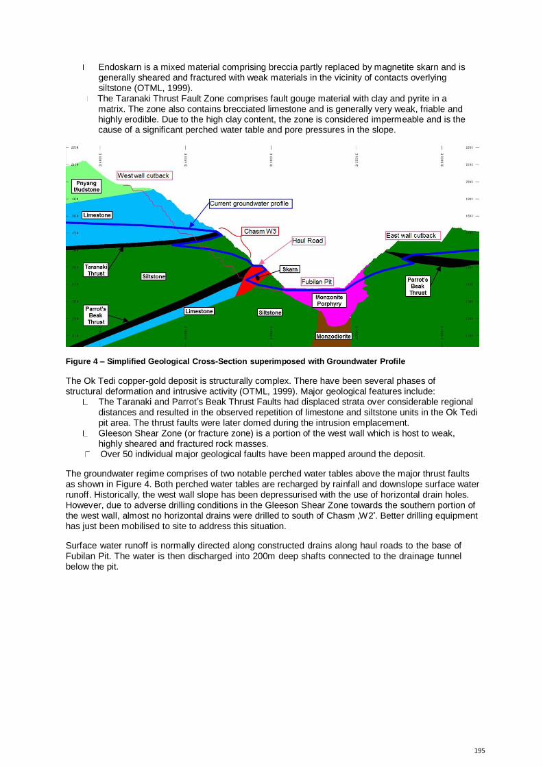
The Taranaki Thrust Fault Zone comprises fault gouge material with clay and pyrite in a matrix. The zone also contains brecciated limestone and is generally very weak, friable and highly erodible. Due to the high clay content, the zone is considered impermeable and is the cause of a significant perched water table and pore pressures in the slope.
Figure 4 – Simplified Geological Cross-Section superimposed with Groundwater Profile
The Ok Tedi copper-gold deposit is structurally complex. There have been several phases of structural deformation and intrusive activity (OTML, 1999). Major geological features include:
The Taranaki and Parrot‟s Beak Thrust Faults had displaced strata over considerable regional distances and resulted in the observed repetition of limestone and siltstone units in the Ok Tedi pit area. The thrust faults were later domed during the intrusion emplacement.
Gleeson Shear Zone (or fracture zone) is a portion of the west wall which is host to weak, highly sheared and fractured rock masses.
Over 50 individual major geological faults have been mapped around the deposit. The groundwater regime comprises of two notable perched water tables above the major thrust faults as shown in Figure 4. Both perched water tables are recharged by rainfall and downslope surface water runoff. Historically, the west wall slope has been depressurised with the use of horizontal drain holes. However, due to adverse drilling conditions in the Gleeson Shear Zone towards the southern portion of the west wall, almost no horizontal drains were drilled to south of Chasm „W2‟. Better drilling equipment has just been mobilised to site to address this situation.
Surface water runoff is normally directed along constructed drains along haul roads to the base of Fubilan Pit. The water is then discharged into 200m deep shafts connected to the drainage tunnel below the pit.

196
Figure 5 – Chasms and Geological Features superimposed onto Ok Tedi pit shell: Lithological boundaries (left); Major Faults and Gleeson Shear Zone (right)
4. Development of Chasms
The location of chasms which developed at Ok Tedi in the last 10 years are shown and named on Figures 1 & 2. It is important to emphasize that each chasm formed over a significant period of time from months to several years and was not a catastrophic, single-event slope failure.
The chasms have enlarged by a combination of different modes of instability. However, in all circumstances, uncontrolled surface water flow had initiated and progressively eroded and undercut the walls of the chasms. Wall failure modes include block toppling, planar and wedge sliding along pervasive structures and slip circle failure through weak rock and residual soil masses. By way of example, Figure 6 illustrates the failure mechanism during the development of Chasm „S3‟ below the haul road into Fubilan Pit (OTML, 2013):
1. Friable material in upper benches had been shotcreted to minimize erosion; Horizontal weep holes of up to 15m depth were drilled into the face to reduce pore pressures in the benches.
2. Combination of surface water runoff from rainfall and groundwater from weep holes progressively eroded cohesive elements within wedge defect planes on unsupported lower bench.
3. Small wedge on lower bench fails after a high intensity rainfall event and undercuts the shotcreted bench above which failures shortly thereafter.
4. From the location in Figure 6, this mechanism progressed vertically upwards 45m, and down a further 15m for a period of approximately 9 months before it was arrested by competent rock mass conditions in the slope.

197
Figure 6 – Chasm S3 Failure Mechanism
Figures 7 & 8 illustrate recent developments within the W3 west wall chasm through block toppling and progressive rotational sliding or slip circle failure mechanisms, respectively:
1. The slope near chasm „W3‟ is saturated due to a perched groundwater table above the Taranaki Thrust Fault. Groundwater pressures fluctuate significantly depending on the amount of rainfall over a 48 hour time period.
2. In both cases (Figures 7 & 8), surface water flow progressively caused erosion and undercutting of blocks or the toe of slip circles.
3. Tension cracks formed over time and dilated as the failure mechanism was developing. 4. Significant deformation was observed by slope monitoring systems in the days prior to
collapse. Personnel & equipment were evacuated from the haul road below approximately 3 hours prior to collapse when deformation rate thresholds were exceeded.
5. Both collapses occurred during a heavy rainfall event of 170mm in 24 hours. The 50m wide haul road into Fubilan Pit was completely blocked by debris, causing significant disruptions to mine operations.
6. Figure 10 shows the progressive enlargement of Chasm W3 over 16 month period.
Figure 7 – Chasm W3 Undercutting & Block Toppling Failure Mechanism

198
Figure 8 – Chasm W3 Progressive Toe Erosion & Slip Circle Failure Mechanism
Chasm W3 began forming in May 2005 (Figure 9) as a series of small scale wedge failures driven by erosion from surface water and rainfall. These processes continued over time, even with the intermittent implementation of ground support and surface water management strategies. Comparative photographs in Figure 10 illustrate the recent rate of the rate of Chasm W3 enlargement as a result of progressive small scale failures.
Figure 9 – Onset of Chasm W3 developing in 2005
Figure 10 – Progressive enlargement of Chasm W3 between 2013 and 2014

199
Periodic inadequacies in surface water management as a result of failures and/or operational errors (e.g. blocked drains and inappropriate water diversion) have had significant short-term influences on chasm enlargement. For example:
Chasm W4 formed within a two month period in 2012 as a result of directing all surface water runoff from the west wall cutback operation down that location on the slope.
The majority of erosion within Chasm W1 occurred in a six month period due to poorly managed surface water runoff in 2005. Debris flows with run-out distances of over 100m were observed on the pit floor.
Chasm W3 enlarged significantly in the last 12 months following a failure which damaged and later destroyed the drainage system above the chasm crest. Several debris flows onto the main haul road have occurred since, causing significant production delays.
5. Surface Water Management & Ground Support
Lined drainage systems have been implemented to enable efficient water flow, reduce scouring and prevent surface water flowing downs slopes.
Chasm wall failures damaging lined drains above the crest of Chasm W3 have been the prime driver for the enlargement observed between 2013 and 2014 (details in Figure 13).
Recent reinstatement of lined drains diverting surface water away from Chasm W3 (Figure
11) has assisted in reducing the rate of enlargement. However, these drains have already overflowed and caused minor scouring of the haul road.
As with most large scale mining operations, ancillary equipment for maintaining drainage systems is seldom available as needed. Blockages in drains causing scouring of haul roads and uncontrolled water diversion down pit slopes often take significant time to remediated due to lack of equipment availability. The equipment is in high demand during brief periods of better weather.
Figure 11 – Examples of Erosion-reducing Mesh and Surface Water Flows in Concrete Drains
Over the last decade, numerous ground support methods have been trialed to arrest chasm enlargement with varying degrees of success. These include:
Grouted piles (typically 15m deep) at the crest of benches and access ramps above and below chasms.
Successfully arrested enlargement of Chasms S3 & S4; Temporarily reduced the rate of enlargement in Chasm W3 for a period of
approximately 12 months (Figure 12).

200
Mesh and shotcrete of highly friable bench faces. Successfully arrested erosion in the upper benches of Chasm S3; Temporarily reduced the rate of erosion above Chasm W3 (Figure 12). Unsuccessful in portions above Chasm W3 where shotcrete failed from excess pore
pressure build up behind the face, even with the installation of weep holes. Rock-filled gabion baskets and large concrete blocks to reduce toe erosion.
Gabion baskets temporarily reduced the rate of toe erosion at Chasm W3 before being undercut and failing due to excess surface water flow.
Large concrete blocks (i.e. rail sleepers leftover from the tunnel boring machine construction of the drainage tunnel) were successfully used for 2-3 years to arrest Chasm W3 toe erosion and enlargement.
The implementation of chasm ground support has been both proactive and reactive. For example:
Ground support installation for Chasm S3 & S4 began following the first failures below the haul road and continued until chasm enlargement ceased.
Initial drain systems at Chasm W3 were unlined, leaking and scouring. The quality of drains was progressively improved with HDPE lining and shotcreting. However, most of these measures were damaged and leaking within less than a year of their installation.
Implementation of ground support along the crest of Chasm W3 did not commence until the chasm was at least 50m wide and nearly 120m high in 2011 (i.e. six years after it was first identified). By then, many areas were inaccessible and as a result, it was less effective.
Figure 12 – Examples of Failed Grouted Piles, Mesh and Shotcrete

201
6. Risks & Control Measures
The major risks associated with the chasms are (OTML, 2013):
Safety risks associated with uncontrolled and unmanaged ground movement resulting from progressive failures in the chasms could result in major consequences such as serious injuries, fatalities and equipment damage.
Economic risks involving short-term production losses due to haul road blockage following failure events, particularly associated with Chasm W3.
Economic risks involving permanent loss of access to the ore body through the continued enlargement and potential joining of Chasms W3 and S3.
The economic risks are being managed through ongoing review and maintenance of surface water drainage. Debris catchment bunds below Chasm W3 are regularly maintained to reduce the likelihood of spillage onto the haul road into Fubilan Pit. Chasm W3 enlargements in 2013 and 2014 which substantially impaired mine production for several weeks have significantly increased the priority of surface water management, permitting the construction of new road and drain systems as shown in Figure 13. In order to reduce the likelihood of further production losses and reduce the likelihood of permanent haul road damage into Fubilan Pit, the following controls are also planned:
Construction of an additional preventative duplicate drain system (Figure 13); Horizontal drain holes to reduce pore pressure in the slopes where practicable; Budgeting for significant ground support (i.e. grouted piling and mesh & shotcreting of friable
slopes as mining progresses) and surface water management strategies for the west wall cutback.
Figure 13 – Surface Water Management – Failures, Solutions & Preventative Planning
Safety risks are being managed with a combination of operational and slope monitoring controls: Implementation geotechnical hazard awareness and daily inspections and hazard reviews; Debris catchment bunds and traffic management on haul road (lighting towers during night
shift and spotters to divert traffic if debris flows are initiated); Slope monitoring systems are used for the early detection of slope instabilities and are
currently capable of detecting movements of less 10m2
of the slope face. Two levels of deformation alarm thresholds have been set to prompt geotechnical engineers to:
Carry out inspections & rigorously review the monitoring data or; Instigate critical monitoring minimising access to the haul road or to close the haul
road altogether.

202
7. Conclusions
The majority of challenges being faced by erosion-driven instabilities at Ok Tedi Copper-Gold Mine are an example of a “too little, too late” response. There are a number of reasons behind this, including:
When Chasm W3 was only 15m high in 2005 (Figure 9), nobody could have predicted it would propagate vertically by 1200% through small scale progressive failures.
As there are over 300 days of wet weather, availability of shotcreting equipment is scarce, so often supporting slope faces or lining drains is delayed. Similarly, drilling for the installation of grouted piles in weak ground is impaired during wet weather.
The instabilities that affected the surface water drain systems occurred in the wettest times of the year making remediation work more difficult.
Management of chasm remedial activities was and remains to be a complex exercise due to the amount of variables, uncertainties and limitations involved while attempting to maximise profits from the mining operation. These include:
An ever-evolving understanding of geological, major structure and hydrogeological conditions. Uncertainties in predicting whether a bench failure could eventually enlarge to form a chasm
and therefore, whether appropriate ground support is required and how soon. Limitations installing ground support and undertaking remedial work during poor weather
conditions which can be experienced any time and for prolonged times throughout the year. Without these challenges and lessons learnt over the last decade, the operation would be less much prepared for the 1,000m high west wall cutback which is currently in its early stages of mining.
References
Baczynski, NRP, Sheppard, IK, Smith, KJ, Simbina, P & Sakail R 2008, Toppling Slope Failure – Predicted Versus Actual, Ok Tedi, Papua New Guinea, proceedings of the Southern Hemisphere International Rock Mechanics Symposium (SHIRMS), Perth, Australia.
England, JK, 1993. Copper concentrator practice at Ok Tedi Mining Limited, Ok Tedi, Papua New Guinea, in Australasian Mining and Metallurgy: The Sir Maurice Mawby Memorial Volume (eds: JT Woodcock and JK Hamilton), pp661-665 (AusIMM: Melbourne).
OTML 1999, Risk-Based Slope Design Optimisation Study for the Ok Tedi Copper-Gold Mine, Ok
Tedi Mining Limited Internal & Unpublished Report. OTML 2012, Mine Life Extension Feasibility Study, Ok Tedi Mining Limited Internal & Unpublished
Report. OTML 2013, Chasm Formations Preliminary Geotechnical Review, Ok Tedi Mining Limited Internal &
Unpublished Report.