managing the copper loop in the 21st...
TRANSCRIPT

Managing the Copper Loop in the
21st Century
Definition A loop management system (LMS) is a system that automates copper looprelated tasks that are normally performed manually by a technician. The goal of an LMS is to reduce the need for manual intervention related to tasks such as provisioning, loop qualification, testing and troubleshooting, documentation, and recovery from failures. The major benefits attached to this include better service levels and response time, lower operational costs, and faster service provisioning.
Overview This tutorial will address the issues, solutions, and benefits related to an LMS within the context of the copper loop.
Topics 1. Automated LMS within a Competitive CO Environment 2. Closing the Loopholes in the Local Loop 3. What Is an LMS? 4. Key Issues and Solutions 5. Benefits 6. Conclusion Self-Test Correct Answers Glossary

Web ProForum Tutorials http://www.iec.org
Copyright © The International Engineering Consortium
2/21
1. Automated LMS within a Competitive CO Environment With the deregulation of local telecommunications services, a number of issues have emerged that are preventing the level of competitive service offering that could otherwise be achieved. The market is crying out for higher-speed access, faster service provisioning, and guarantees on service levels—all at a reasonable cost.
With the advent of digital subscriber line (DSL) technologies, many service providers are choosing to provide their high-speed service offerings through the existing copper loop, which extends from the central office (CO) into the customer premises. Although attractive in nature, the use of these technologies is pushing the capabilities of existing loops to their limits. This situation, coupled with the number of different players with access, is generating a greater level of activity centered on the use, maintenance, and management of the copper loop and the services running over it.
Although incumbent local exchange carriers (ILECs) are unbundling the loop for use by competitive local exchange carriers (CLECs), they cannot turn over the management of this most critical part of their network. On the contrary, they must enhance their management tools and enable them to better monitor the activity on the loop. Furthermore, particularly in a line-sharing environment, they must ensure that the traffic and test signals or tones originating from the CLEC do not affect the quality of service offered to their customers. Similarly, CLECs have a particular challenge in that they must be equipped to monitor the state of the local loop and have the means to offer a competitive service—despite not actually having direct control of the loop. For example, in the eventuality of new services, CLECs must be able to pretest or qualify the loop to validate that it is in good order. Also, when service problems arise, CLECs must be able to isolate the source of the problem rapidly, even if it happens to be on the ILEC–owned loop.
2. Closing the Loopholes in the Local Loop These market conditions prompt several questions: What if the local copper loop was viewed as an intelligent network (IN) element? What if we could remotely administer and manage it?
Such a tool, which will be known in this tutorial as an LMS, could be used by service providers for the purpose of maximizing the level of control they can have on the last mile of the network. For CLECs, this system would remove much of their dependence on ILECs, thereby accelerating the deployment of new technologies and guaranteeing previously unseen service levels. For ILECs, an

Web ProForum Tutorials http://www.iec.org
Copyright © The International Engineering Consortium
3/21
LMS would greatly facilitate the management of a vast infrastructure that was, for the most part, never designed to support the emerging protocols and applications. It would allow them to manage loop provisioning and testing more effectively, address spectrum management issues within binder groups and cables, and, of course, automate the documentation of the loop connectivity.
3. What Is an LMS? A complete LMS consists of a software component and an intelligent hardware component. The hardware typically consists of some form of switching fabric with interfaces to both line and equipment on either side of the switching fabric. This functionality is the electronic equivalent of the functionality of a main distribution frame (MDF) and an intermediate distribution frame (IDF), so the term automated distribution frame (ADF) will be used to describe it.
The hardware portion of the LMS or ADF sits between the MDF and the access equipment (for CLECs) or switching equipment (for ILECs). As shown in Figure 1, these elements are known generically as line equipment (LE).
Figure 1. Loop Management System Architecture
The ADF is then used to connect specific loops to the line equipment. It must provide full nonblocking switching functionality across its full matrix in order to provide complete physical provisioning capabilities. It should also include test heads that are capable of characterizing the copper loop, thereby qualifying it for use with the selected service.
Because it sits as a part of the network infrastructure, an ADF must be designed and built to be passive and transparent to protocols. It must solve problems, not

Web ProForum Tutorials http://www.iec.org
Copyright © The International Engineering Consortium
4/21
create them. Also, a great deal of robustness (redundancy) and fault tolerance must be built into the system.
• The system must be able to retain all of its circuit connections even during a complete loss of power.
• All of its hardware and software components must be hot-swappable, allowing on-the-fly maintenance without further loss of service.
• The system must support multiple and redundant key components, such as controller cards and power supplies.
• The system must be able to compensate for loss or failure of internal switching paths without the loss of a circuit or service.
In short, there can be no single point of failure in the system.
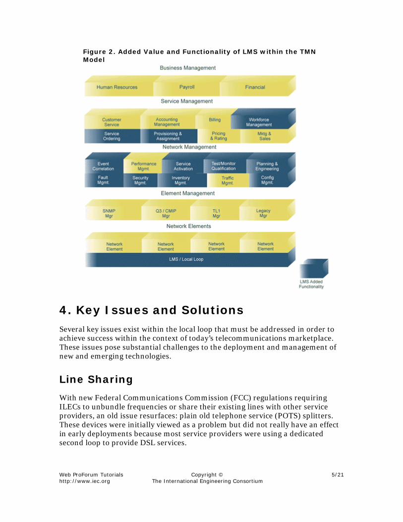
The software portion of the LMS must be well integrated into the operations support system (OSS). While there should be a console for specific tasks relating to the configuration and management of the LMS, the bulk of its functionality must be accessible from existing OSS applications and consoles. In the telecommunications management network (TMN) model shown in Figure 2, one can see numerous service management and network management applications that could greatly benefit from interacting directly with an LMS.
With tight integration, data and inventory information can be shared and updated, and test suites can be automated to run during the loop-qualification portion of the provisioning process or when a trouble ticket is opened. Of course, once the loop is qualified and the circuit design process is completed, it is connected to the line equipment and the service is turned on. All of this is done with little or no intervention from a technician.
Web ProForum Tutorials http://www.iec.org
Copyright © The International Engineering Consortium
5/21
Figure 2. Added Value and Functionality of LMS within the TMN Model
4. Key Issues and Solutions Several key issues exist within the local loop that must be addressed in order to achieve success within the context of today’s telecommunications marketplace. These issues pose substantial challenges to the deployment and management of new and emerging technologies.
Line Sharing
With new Federal Communications Commission (FCC) regulations requiring ILECs to unbundle frequencies or share their existing lines with other service providers, an old issue resurfaces: plain old telephone service (POTS) splitters. These devices were initially viewed as a problem but did not really have an effect in early deployments because most service providers were using a dedicated second loop to provide DSL services.
Web ProForum Tutorials http://www.iec.org
Copyright © The International Engineering Consortium
6/21
Now, with line sharing, splitters are back in the thick of things. The problem with splitters is their placement. If they are installed on or near the ILEC’s MDF, they are effectively sitting between any test equipment and the local loop. For many tests, this situation is a big problem, regardless of the test vendor. Many tests cannot be accurately run through a splitter, as the signal will have its high or low frequencies filtered out, depending on whether the tests are conducted from the voice switch or the digital subscriber line access multiplexer (DSLAM).
A common solution being implemented today has the splitter sitting in the front of the DSLAM. This allows for accurate testing through a test access device (either a test access switch or a cross-connect) positioned in front of the splitters. There are, however, two problems remaining. First, any attempt to change the DSL service for a different service type or service provider cannot be managed from a distribution frame without affecting the POTS service. Second, in a collocation application, the ILEC’s POTS service must run through the CLEC’s collocation cage to access the splitter.
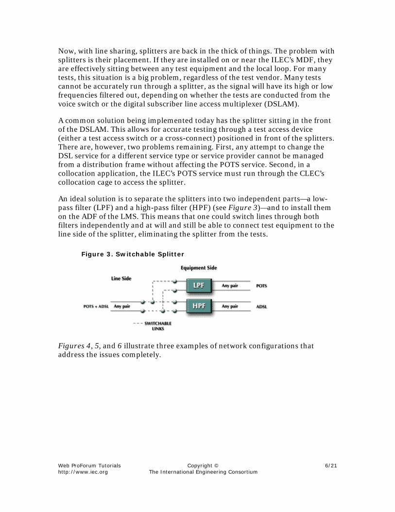
An ideal solution is to separate the splitters into two independent parts—a low-pass filter (LPF) and a high-pass filter (HPF) (see Figure 3)—and to install them on the ADF of the LMS. This means that one could switch lines through both filters independently and at will and still be able to connect test equipment to the line side of the splitter, eliminating the splitter from the tests.
Figure 3. Switchable Splitter
Figures 4, 5, and 6 illustrate three examples of network configurations that address the issues completely.

Web ProForum Tutorials http://www.iec.org
Copyright © The International Engineering Consortium
7/21
Figure 4. Line-Sharing Configuration #1
Figure 5. Line-Sharing Configuration #2
Figure 6. Line-Sharing Configuration #3

Web ProForum Tutorials http://www.iec.org
Copyright © The International Engineering Consortium
8/21
Lifeline for Voice over DSL (VoDSL)
As more and more customers get access to broadband services through DSL, the current practice of having multiple voice lines and separate data lines may be replaced by VoDSL service. Significant cost savings can be achieved by aggregating these multiple services into one packetized line.
Although current data services are quite reliable and improving, they are not yet quite as reliable as dedicated traditional voice services. A voice service is required to be available at all times. In the event of power failure, the telephone equipment is required to function normally in order to allow emergency responses. VoDSL also requires this lifeline feature.
For residential applications, where an asymmetric digital subscriber line (ADSL) service is installed, the issue is not so significant because the baseband is reserved for the POTS line. For business applications, however, a symmetrical DSL (SDSL) service having no baseband POTS is more popular. In this case, an LMS will prove invaluable to guarantee lifeline by offering access to a standby POTS service. This is a more elegant solution than having batteries as a power-failure backup in the customer premises equipment (CPE), as batteries are labor-intensive and require maintenance.
As shown in Figure 7, when the DSLAM detects that the CPE side is not responsive, it will report an alarm to a software monitor that will send the proper command to the LMS to switch over the equipment to a POTS service.
Figure 7. Lifeline Application for VoDSL

Web ProForum Tutorials http://www.iec.org
Copyright © The International Engineering Consortium
9/21
Wholesale Application
With the unbundling of the local loop, a new class of service provider will emerge. The ILEC (or a new subsidiary company specializing in managing the local loop) or a big CLEC sitting between the ILEC and the other service providers can serve as a wholesale provider of the local loop.
The local loop will become again a valuable resource that can be leased and generate revenue. An LMS will become a key tool in managing this resource. Many customers will change hands—perhaps more than once—to multiple service providers. These include non–facilities-based service providers with reseller status who are electronically bonded to the facilities-based carriers. The current practice is labor-intensive and therefore time-consuming and error-prone. With an LMS, positioned as in Figure 8, loops are just mouse clicks away from being passed to someone else—once all the loops are integrated and documented. It is an operation that takes minutes rather than hours or days.
Figure 8. Wholesale Application
This ease of process triggers notions of being able to provision services à la carte, whereby, for example, a user could self-provision a service via the Web on a pay-per-use basis with both variable bandwidth and service-provider choices.

Web ProForum Tutorials http://www.iec.org
Copyright © The International Engineering Consortium
10/21
Loop Qualification and Testing
The bulk of existing copper loops was meant to support POTS services and was never designed to support high-bandwidth applications. Thus, the lines were conditioned to optimize the zero to 4-kHz bandwidth range in which POTS runs. Many of the traditional techniques used to condition these lines can interfere with higher bandwidth protocols such as integrated service digital network (ISDN) and DSL.
Loop testing and qualification currently requires on-site intervention by an ILEC technician. Unfortunately, service providers presently have no cost-effective means of accurately prequalifying a line before deployment. Additionally, many current deployments rely solely on checking the loop records to verify if there are load coils or other conditions present that could interfere with the deployment of the service. Suffice it to say that these records are not always accurate. The service is then deployed with no further testing or qualification. This methodology leads to situations where the service is deployed to the subscriber and then disconnected as a result of excessive problems. The subscriber is then informed, after the fact, that the service is not available. In addition to the time, energy, and money needlessly expended, this situation leads to a poor customer perception of the service provider. With an LMS, loop testing and qualification can be validated by the service provider before a service is declared available for a customer. This function can be achieved without the need to send out a technician, and it can be performed much quicker. Additionally, loop qualification records are stored automatically so that the state of the loop at any given time can be compared to a base point.
It has been suggested that test access and even testing equipment be integrated directly into DSLAMs. While this could prove useful for some bit-error-rate testing (BERT) and possibly even higher-level protocol testing, testing and characterization of the loop should be left separate from the DSLAM for the following reasons:
• Adding loop testing equipment capability to DSLAMs will raise the cost of the overall test equipment investment. Every time a new DSLAM is purchased, additional test equipment is acquired unnecessarily. This recurring cost for the test equipment portion that is integrated in the DSLAM would be eliminated if the loop testing equipment were a part of the network infrastructure and revolve around a centralized, vendor-independent LMS.
• The loop must be connected to a particular port on the DSLAM before the testing can occur. If the loop fails to qualify and cannot be conditioned, it must be disconnected and another connected in its place. This results in a more labor-intensive process.
Web ProForum Tutorials http://www.iec.org
Copyright © The International Engineering Consortium
11/21
• As mentioned previously, many tests (e.g., load coil detection) cannot be accurately run through a splitter. Thus, if line-sharing mode is used, the test equipment cannot be placed at the DSLAM. It must be in front of the splitters, as would be the case with an LMS.
Remote Management
Unbundling the local loop for use by CLECs introduces the situation whereby the delivery of a service to a customer now involves two companies bound together by legislation and service-level agreements (SLAs). While the ILEC is solely responsible for managing the physical loop, both service providers hold final accountability for the condition and quality of the service they are delivering to their customers. They must, therefore, be well-equipped to handle maintenance-related issues.
For a CLEC, a collocation arrangement in the CO is somewhat like a large remote terminal. When they are put in place across the country, staff must be hired to manage them. Generally, though, these sites are not large enough to justify a full-time technician or, if so, certainly not on three shifts. Access to the premises, especially on off-hours, is often a problem. This issue is a large impediment to offering guaranteed service levels.
For both the ILEC and the CLEC, the newly competitive environment coupled with the delivery of high-speed Internet access for business users will require the offering of guaranteed service levels. The old methods of dispatching technicians to investigate problems and lengthy reporting mechanisms just will not suffice. More sophisticated on-line tools must be made available to the network management crew.
With an LMS, service providers are equipped to isolate problems quickly as well as assign responsibility for their correction, whether it is internal or external (i.e., ILEC– or CLEC–related), without having to dispatch a technician. In many cases, such as for an equipment failure, the service can be restored on the fly by provisioning a new equipment port directly from the network operations center (NOC). With an open architecture that would allow an LMS to integrate seamlessly into network management systems, this feature could be automated to enable a self-healing access network.
Flow-Through Provisioning and Future Requirements
Several companies have begun initiatives aimed at automating the provisioning cycle. Given the level of automation and manageability present in today’s line and network equipment, it is possible to automate many of the tasks in the

Web ProForum Tutorials http://www.iec.org
Copyright © The International Engineering Consortium
12/21
provisioning cycle. There is, however, still one barrier to the completely automated provisioning system: the physical loop. If the loop can be integrated into the community of managed devices and procedures that make up an automated flow-through provisioning system, the last barrier will be removed.
An LMS is the catalyst that can facilitate this process. With a fully automated provisioning system, service providers can offer true service-on-demand and modify a subscriber’s service type as requested. This service can be offered through various means, such as customer representatives, Web sites, fax, or even automated 800 services.
Adding the intelligence and automation of an LMS to the physical layer breaks down the barriers to even more forward-looking applications and functionality. One can now imagine the complete automation of many tasks and facets of network provisioning and management.
• automated physical network discovery
• automated network inventory
• policy-based management with automated network configuration based on policies
• self-healing networks
System Application
Ideally, as mentioned earlier, the LMS hardware would replace a distribution frame and would in effect become an ADF. Additionally, with an integrated isolation displacement connector (IDC) punch-down connector interface, the ADF can act as the demarcation point, or point of termination (POT) between the ILEC and the CLEC.
This gives the service provider the ability to control the demarcation point remotely. From the NOC, it is able to test and monitor looking outward onto the loop or looking inward toward its own network using a loopback function.
For added flexibility, an LMS’s architecture should allow different faceplate modules carrying the connectors of choice (IDC punch-down, telco, wire-wrap, etc.). With this system in place, service providers could then assign, reassign, and troubleshoot residential and business subscriber circuits at will. An LMS in a CO environment will allow them to do so without ever dispatching a technician to provision a circuit or remedy the fault.

Web ProForum Tutorials http://www.iec.org
Copyright © The International Engineering Consortium
13/21
With an LMS in place, service providers will be able to provision any service (ISDN, POTS, DSL, and any future services such as asynchronous transfer mode [ATM]) in minutes, following a customer request (see Figures 9 and 10).
Figure 9. Today ’s Configuration
Figure 10. Vision Configuration

Web ProForum Tutorials http://www.iec.org
Copyright © The International Engineering Consortium
14/21
5. Benefits An LMS in the service provider’s network allows the following benefits:
• decreased ILEC/CLEC dependence—Loop testing and qualification can be performed by either party without the need to go through the other or send out a technician.
• improved SLAs—Not only are there standby components that can handle any internal failure, this extra point of control in the network allows for troubleshooting and rerouting around any other network problem in the local loop, thus allowing much faster network restoration times. This concept can even be automated to form a self-healing network.
• additional loop maintenance functionality—In-service, nonintrusive measurement devices (INMDs) can be integrated in the hardware platform to detect loop problems before customers report them. Also, the loop condition can be qualified for being able to support higher-speed services (such as DSL) before they are provisioned.
• network management simplification—One network element can be used to provide any-to-any access to all existing and future services, independent of the networking equipment used. This function is integrated into the distribution frame along with the testing tools and splitters, as required.
• immediate response time—Customer requests are handled within minutes, bringing revenue on stream more quickly. This is real-time service-on-demand like never seen before.
• enhanced reliability—Remote provisioning and maintenance capabilities allow for greater network reliability, as the point of interconnection need not be manipulated anymore, and all record keeping is updated automatically.
• dim lights approach to operations—On-site visits (truck rolls) are practically eliminated as the bulk of operations and maintenance activities can now be handled remotely.
• enhanced customer retention and additional revenue days—Quicker turn-up time offers an overall better service along with additional revenue days. Many of the items above also result in better service that allows for the retention of the actual customer base.

Web ProForum Tutorials http://www.iec.org
Copyright © The International Engineering Consortium
15/21
• first-to-market and just-in-time marketing—More automation means that you will get the edge over your competitors in the race to test and launch future services.
6. Conclusion The telco market is increasingly competitive. Its players will differentiate themselves through higher-quality offerings that exceed customer expectations. In this environment, an LMS is the missing link required for service providers to have a network management infrastructure that allows for the cost-effective deployment of higher-speed services with enhanced and guaranteed service levels.
An LMS also enables the move to tighter integration between the various layers of the TMN model and becomes the agent that integrates the local loop into the community of remotely managed IN devices.
Self-Test 1. ILECs are turning over the management of the local loop to CLECs.
a. true
b. false
2. The goal of LMS is to reduce the need for manual intervention.
a. true
b. false
3. The biggest problem with splitters is their __________________.
a. size
b. age
c. placement
d. strength
4. The current practice of having multiple voice lines and separate data lines may be replaced by _______________.
a. SDSL
Web ProForum Tutorials http://www.iec.org
Copyright © The International Engineering Consortium
16/21
b. ADSL
c. IDSL
d. VoDSL
5. _______________ is used in residential applications.
a. SDSL
b. ADSL
c. IDSL
d. VoDSL
6. _______________ is used in business applications.
a. SDSL
b. ADSL
c. IDSL
d. VoDSL
7. The bulk of existing copper loops was designed to support high-bandwidth applications.
a. true
b. false
8. With LMS, service providers will be able to provision any service.
a. true
b. false
9. Which of the following is not a result of LMS in the service-provider network?
a. network management simplification
b. immediate response time
c. more interaction between the ILEC and CLEC
d. just-in-time marketing

Web ProForum Tutorials http://www.iec.org
Copyright © The International Engineering Consortium
17/21
10. Even with LMS, the bulk of operations and maintenance must be handled by technicians.
a. true
b. false
11. An ADF can act as a wholesale application facilitator and a demarcation point between service providers.
a. true
b. false
Correct Answers 1. ILECs are turning over the management of the local loop to CLECs.
a. true
b. false
See Topic 1.
2. The goal of LMS is to reduce the need for manual intervention.
a. true
b. false
See Topic 3.
3. The biggest problem with splitters is their __________________.
a. size
b. age
c. placement
d. strength
See Topic 4.
Web ProForum Tutorials http://www.iec.org
Copyright © The International Engineering Consortium
18/21
4. The current practice of having multiple voice lines and separate data lines may be replaced by _______________.
a. SDSL
b. ADSL
c. IDSL
d. VoDSL
See Topic 4.
5. _______________ is used in residential applications.
a. SDSL
b. ADSL
c. IDSL
d. VoDSL
See Topic 4.
6. _______________ is used in business applications.
a. SDSL
b. ADSL
c. IDSL
d. VoDSL
See Topic 4.
7. The bulk of existing copper loops was designed to support high-bandwidth applications.
a. true
b. false
See Topic 4.
8. With LMS, service providers will be able to provision any service.
a. true

Web ProForum Tutorials http://www.iec.org
Copyright © The International Engineering Consortium
19/21
b. false
See Topic 4.
9. Which of the following is not a result of LMS in the service-provider network?
a. network management simplification
b. immediate response time
c. more interaction between the ILEC and CLEC
d. just-in-time marketing
See Topic 5.
10. Even with LMS, the bulk of operations and maintenance must be handled by technicians.
a. true
b. false
See Topic 6.
11. An ADF can act as a wholesale application facilitator and a demarcation point between service providers.
a. true
b. false
See Topic 4.
Glossary ADF automated distribution frame
ADSL asymmetric digital subscriber line
ATM asynchronous transfer mode
Web ProForum Tutorials http://www.iec.org
Copyright © The International Engineering Consortium
20/21
BERT bit-error-rate testing
CLEC competitive local exchange carrier
CO central office
CPE customer premises equipment
DSL digital subscriber line
DSLAM digital subscriber line access multiplexer
FCC Federal Communications Commission
HPF high-pass filter
IDC isolation displacement connector
IDF intermediate distribution frame
ILEC incumbent local exchange carrier
IN intelligent network
INMD in-service, nonintrusive measurement devices
ISDN integrated services digital network
LE line equipment
LMS loop management system
Web ProForum Tutorials http://www.iec.org
Copyright © The International Engineering Consortium
21/21
LPF low-pass filter
MDF main distribution frame
NOC network operations center
OSS operations support system
POT point of termination
POTS plain old telephone service
SDSL symmetrical digital subscriber line
SLA service-level agreement
TMN telecommunications management network