mandroid - · pdf filefdin – controls the fade-in time of the led in the h11f1. left is...
TRANSCRIPT

MaNdroid FX TYPE: Pitch Modulator
Based on Hazelwanter Pitch Shifter © 2017 madbeanpedals 8.8 update: pgs. 11 & 12
4.4” W x 1.625” H
Due to the split-rail power scheme, this project requires an isolated 9v supply. Daisy-chained supplies (ex. One Spot using multiple taps) will not work for the Mandroid.
Terms of Use: You are free to use purchased circuit boards for both DIY and small commercial operations. You may not offer these PCBs for resale or as part of a “kit” in a commercial fashion. Peer to peer re-sale is, of course, okay.

2
R1 1M D1 3.6vR2 1M D2 3.6vR3 10k D3 1N5817R4 10k D4 - D17 1n914R5 5k1R6 5k1 Q1 2n3904R7 22kR8 10k IC1 4558R9 4k7 IC2 4558R10 33k IC3 HT8950R11 330RR12 100k OPTO H11F1R13 10kR14 330R MODE 1P12TR15 1k SPLODE MomentaryR16 1k ROB/VIB MomentaryR17 47R TRIG SPDTR18 47RR19 1k EXT 1/8" Jack
C1 100n FDIN 100kC2 220pF FDOT 100KC3 330pF DRIVE 50kC4 1uFC5 100n DRY 10kBC6 100n FINE 5kBC7 4u7 LEVEL 100kAC8 220n WET 10kBC9 220uF WARP 250kBC10 100uFC11 100uFC12 10uF
Jack
Trimmers
Pots
B.O.M.Resistors
Caps
Didoes
Transistor
ICs
Optocoupler
Switches

3
Value QTY Type Rating47R 2 Metal / Carbon Film 1/4W330R 2 Metal / Carbon Film 1/4W
1k 3 Metal / Carbon Film 1/4W4k7 1 Metal / Carbon Film 1/4W5k1 2 Metal / Carbon Film 1/4W10k 4 Metal / Carbon Film 1/4W22k 1 Metal / Carbon Film 1/4W33k 1 Metal / Carbon Film 1/4W100k 1 Metal / Carbon Film 1/4W1M 2 Metal / Carbon Film 1/4W
220pF 1 Ceramic / MLCC 16v min.330pF 1 Ceramic / MLCC 16v min.100n 3 Film 16v min.220n 1 Film 16v min.1uF 1 Film 16v min.4u7 1 Electrolytic 16v min.
10uF 1 Electrolytic 16v min.100uF 2 Electrolytic 16v min.220uF 1 Electrolytic 16v min.3.6v 2 Zener
1N5817 11n914 132n3904 14558 2
HT8950 1H11F1 11P12T 1 Rotary Switch
Momentary 1 FootswitchMomentary 1 Pushbutton Switch
SPDT 1 or, SPST1/8" Jack 1 see link
100k 2 Bourns 3362p50k 1 Bourns 3362p
10kB 2 PCB Right Angle 16mm5kB 1 PCB Right Angle 16mm
100kA 1 PCB Right Angle 16mm250kB 1 PCB Right Angle 16mm
Shopping List

4
This project requires parts that, unfortunately, no single supplier is likely to have. The following links should help locating everything you need.
3.6v Zener (3.3v Zener should work as a substitute): http://www.mouser.com/ProductDetail/Nexperia/1N4729A133/?qs=sGAEpiMZZMtQ8nqTKtFS%2fISyHb0gtGyW3gFTqySUy%252bs%3d
H11F1: http://smallbear-electronics.mybigcommerce.com/photocoupler-h11f1/
HT8950: eBay is probably a good source – ex: http://www.ebay.com/itm/HT8950-Holtek-Voice-Modulator-DIP-IC-3-EACH-/391320657847?epid=1726593497&hash=item5b1c875fb7:g:38EAAOSwIwhWR39M
or, http://www.futurlec.com/Others/HT8950pr.shtml or, http://vakits.com/ht8950-voice-modulator
1P12T: http://smallbear-electronics.mybigcommerce.com/26mm-enclosed-1p2-12t-0227b/
Momentary Footswitch (SPLODE): http://www.bitcheslovemyswitches.com/#!/SPST-Soft-Touch-Momentary-Footswitch-Normally-Open/p/10220659 or, http://smallbear-electronics.mybigcommerce.com/momentary-spst-no-soft-touch/
Momentary Pushbutton (ROB/VIB): http://www.bitcheslovemyswitches.com/#!/Green-SPST-Pushbutton-Momentary-Switch/p/30912900/category=7189610 or, https://www.mammothelectronics.com/collections/tactile-switches/products/spst-pbs-rbk-al
Mini SPDT Toggle (TRIG): http://smallbear-electronics.mybigcommerce.com/spdt-on-on-0218a/
1/8” Jack (EXT): http://smallbear-electronics.mybigcommerce.com/1-8-mono-pc-mount/
HT8950 Datasheet https://www.sparkfun.com/datasheets/Components/General/8950v110.pdf

5
1590BB Drill Guide
6.83”W x 5.81”H
Photoshop Drill Template: http://www.madbeanpedals.com/projects/Mandroid/Mandroid_DRILL.zip
This template shows two possible locations for the ROB/VIB switch. If using the “tactile” pushbutton linked to Mammoth on pg.4, then use pos2 on the enclosure (that switch is fairly large). The small pushbutton switch linked to BLMS will work in either position.
7.26 Update: I modified this drill template for better placement of ROB/VIB pos1 and moved the DC Jack to the right side. This will make for a much easier build.
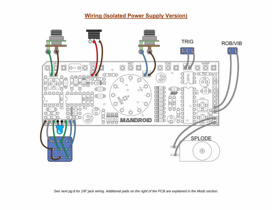
Wiring (Isolated Power Supply Version)
See next pg.8 for 1/8” jack wiring. Additional pads on the right of the PCB are explained in the Mods section.

7
Wiring (Battery Power Version)
If you don’t have an isolated power supply and want to use battery power instead, we have to make an adjustment. Normally a battery has its black lead wired to the ring of a stereo input jack. However, we use mono plugs for our guitars which means once a mono plug is inserted to a TRS jack, the ring and sleeve are grounded. That won’t work for us because we need the black lead from the battery to provide -4.5v! Instead, wire the battery as shown above. The battery negative is always connected to the PCB. The battery positive is switched. What this means is when nothing is plugged into the DC Jack, both the positive and negative sides of the battery are connected to the PCB and power it. If an empty plug (not connected to anything) is inserted in the DC Jack, it disconnects the power and saves on the battery life.

7.26 Update: When using PCB mounted pots, you should offset them from the board. This is because these Alpha rotary switches are a bit taller than the lengths of the potentiometer pins.
You can also use regular solder lug pots, too.

9
Wiring Correction
There is a routing mistake on the schematic with the EXT jack. The T/TN and S/SN connections are flipped. This is very easy to fix. Wire the EXT jack like this:
If you don’t want to use the EXT jack at all, solder wires to the pads to like this:

10
Overview
The Mandroid is based on the Dean Hazelwanter Pitch Shifter project from General Guitar Gadgets and later popularized by the Death By Audio® Robot™. It uses an obscure “voice modulator” chip made by Holtek (now obsoleted). “Normal” operation receives audio input and then modulates it with strange pitching shifting and aliasing into a kind-of robotic voice. It also has the option to add vibrato to the robot voice because why not.
In terms of making it into a guitar effect, the Mandroid will produce strange pitch shifting whose frequency range is set by the Mode switch and Warp pot. It can make faux ring modulator type sounds, weird vibrato, runaway arpeggios and generally make your band members stare at you in disbelief.
The Mandroid has elements from both the “Pitch Shifter” and “Robot” designs and adds a new control: the Splode. Splode is a momentary trigger that will “explode” the pitch shift upward by utilizing a transistor to fade in and fade out an optocoupler in parallel with the Warp knob. Lastly, the Mandroid has an option to use an external trigger in place of the Splode control (to hopefully interface with the upcoming Wumpus capacitive touch project – or something else).
Controls Pots
LEVEL – Total output of the effect. DRY – Dry signal mix. WET – Effect signal mix. WARP – Oscillator/speed control for the modulator chip. FINE – This allows for smaller adjustments to the Warp control (a few cents of pitch shift) – useful if you are trying to tune the pitch shift to a specific note on the guitar. Nominal position is halfway up.
Trimmers
DRIVE – Adds soft clipping to the dry and effect signal paths. Left to 1/3rd is cleanest, ½ to all the way up is dirty. FDIN – Controls the fade-in time of the LED in the H11F1. Left is instant on, right is 1-2 seconds fade in. FDOT – Controls the fade-out time of the LED in the H11F1. Left is instant off, right is 1-2 seconds fade out.
Switches
ROB/VIB - Pushbutton switch to select between the Robot and Vibrato modes. MODE – Switches between the pitch shifting steps available on the HT8950 (set for 8 steps) TRIG – Turns on the Splode control (this will change the WARP setting when turned on). SPLODE – Momentary trigger that automatically changes the Warp control via the H11F1. EXT – Allows for an external input to drive the H11F1 instead of the Splode footswitch. When an external trigger is plugged in, the FDIN and FDOT trimmers are disabled.
Notes
The Mode rotary switch is a 1P12T. This switch has a small ring with a tab to set the maximum number of steps tothe switch. For the Mandroid, insert this tab into the slot labeled “8”.
The Splode control is set for maximum range when pressed. If you want a more subtle control, socket R13 and tryhigher value resistors such as 1k, 2k, etc. This will reduce the maximum brightness of the LED in the H11F1.
You might be wondering if a charge pump could have been used as a power inverter to do the split-rail supplyused in this effect. The answer is you can but it sounds like crap. The typical charge pumps (LT1054,TC1044SCPA, etc) turn this effect into a noisy, heterodyning mess and make it completely unusable. The onlydownside of the method used here is that it requires an isolated supply which most of us are already using (PP2,etc).
If you are using a testing rig for your builds (to rock before you box) make sure you have a ground connectionbetween your input/output jacks on your testing rig and the Mandroid PCB. Normally this connection happensautomatically with the sleeve connection on the 9v pads of PCBs, but in this case the sleeve is providing -4.5v forthe effect!

11
Mods
If you want to go all out, there is an additional mod you can do. The 8th step on the Mode switch gives you access to the “TGU” and “TGD” functions on the HT8950. This means you can use yet another momentary switch to cycle the Modes up or down instead of the rotary switch. This could be fun for rapidly toggling through the modes while you are playing. Doing the mod is simple:
1) Set the tab on the Mode switch to 8 steps (even if you are not doing this mod).
2) Wire up another momentary footswitch. One connection goesto GND (ground) and the other goes to either the UP or DNpads. The ROB pad is not used at all in this project, btw.
Of course, you will need to consider available space when using this mod if you stick with the 1590BB enclosure.
8.8 update: Previously I instructed to set the Mode switch to 7 steps for normal operation and 8 steps if doing the Up/Down momentary switch. This is incorrect. The Mode switch should be set or 8 steps regardless. The 8th step on the switch also gives you the arpeggiator…one of the best parts of the effect!

12
Voltages
IC1 V IC3 V1 22mV 1 0.4022 22mV 2 0.4043 22mV 3 0.4024 -3.19 4 05 0 5 1.166 0 6 1.167 -0.8mV 7 3.168 3.16 8 varies
9 3.06IC2 V 10 1.161 2.8 11 3.162 0 12 1.153 0 13 1.154 -3.19 14 1.135 0 15 3.136 0 16 3.137 80mV 17 3.138 3.16 18 3.13
8.8 update: Corrected voltages (I had previous 8950 voltages transposed on pins). These measurements were taken with the Mode switch in the 8th position. Some voltages will change in other positions.

13