manifold optional parts - steven engineering · 2011. 12. 22. · ∗ when ordering a block plate...
TRANSCRIPT

JIS symbol
A 4
B2
A 4
B2
A 4
B2
8.5
57
Exhaust
A 4
B2
A 4
B2
A 4
B2
8.5
57
BA BAPR
Series S0700 Plug-in Manifold Stacking BaseManifold Optional Parts
Blanking plate
SS0700-10A-1It is used by attaching on the manifold block for being prepared for removing a valve for maintenance reasons or planning to mount a spare valve, etc.
Mass: 25 g
External pilot [-R]This can be used when the air pressure is 0.1 to 0.2 MPa lower than the minimum operating pressure of the solenoid valves or used for va-cuum specifications.Add R to the part numbers of manifolds and valves to indicate the external pilot specifica-tions.An M5 port will be installed on the top side of the manifold’s SUP/EXH block.� How to Order Valves (Example)
S0710 R -5
� How to Order Manifold (Example)∗ Indicate R for an option.
SS0750-08C4FD1-R
External pilot
External pilot
Direct EXH outlet with built-in silencer [-S]
Note) A large quantity of drainage gener-ated in the air source results in ex-haust of air together with drainage.
∗ When ordering this option incorporated with a manifold, suffix “-S” to the end of the manifold part number.
∗ For precautions on handling and how to replace elements, refer to “Specific Product Precautions.”
This is a type with an exhaust port atop the manifold end plate. The built-in silencer exhib-its an excellent noise suppression effect. (Noise reduction: 30 dB)
Individual SUP/EXH spacer
If this spacer is installed instead of a valve, it is possible to add SUP and EXH ports. In this condition, the A port should be an SUP port and the B port an EXH port.∗ Specify the spacer mounting position and
SUP/EXH passage shut off positions by means of the manifold specification sheet.
∗ The spacer comes with a SUP block plate and an EXH block plate.
∗ Electrical wiring is also connected to the spacer mounting position.
SS0700-PR-1
External pilot port
(M5 x 0.8)
Note 1) Not compatible with dual 3-port valves.
Note 2) When the internal pilot type and external pilot type of valves are mixed up on the manifold, or-der the manifold suit-able for the specifica-tions of the external pi-lot valve.
Note 3) Valves with the external pilot have a pilot EXH with individual exhaust specifications and EXH can be pressurized.However, the pressure supplied from EXH should be 0.4 MPa or lower.
D side Valve
Block plate (Ordering not required)
3(R)1(P)
ValveSpacer for
individual SUPEXH
EXHportSUPport
65
S0700-B.qxd 09.4.24 4:38 PM Page 65
Courtesy of Steven Engineering, Inc.-230 Ryan Way, South San Francisco, CA 94080-6370-Main Office: (650) 588-9200-Outside Local Area: (800) 258-9200-www.stevenengineering.com

4.2
9.8
1.5
P
R
P
RP
R
Block indicationlabel
6.4
9.2 1.5
5
2.5
4
P
RP
R
Block indicationlabelP
R
SUP block plate
SS0700-B-PWhen different pressures, high and low, are supplied to one manifold, a SUP block plate is inserted between the stations under different pressures.∗ Specify the number of stations by means of
the manifold specification sheet.
<Block indication label>When using block plates for SUP passage, in-dication label for confirmation of the blocking position from outside is attached. (One label of each)∗ When ordering a block plate for SUP incor-
porated with the manifold, a block indication label is attached to the manifold.
Mass: 0.3 g
EXH block plate
SS0700-B-RWhen valve exhaust affects the other stations on the circuit, insert EXH block plate in be-tween stations to separate valve exhaust.∗ Specify the number of stations by means of
the manifold specification sheet.
<Block indication label>When using block plates for EXH passage, in-dication label for confirmation of the blocking position from outside is attached. (One label of each)∗ When ordering a block plate for EXH incor-
porated with the manifold, a block indication label is attached to the manifold.
Mass: 0.3 g
Back pressure check valve [-B]
SS0700-7A-1It prevents cylinder malfunction caused by other valve exhaust. Insert it into R (EXH) port on the manifold side of a valve which is affec-ted. It is effective when a single action cylin-der is used or an exhaust center type solenoid valve is used.∗ When a check valve for back pressure pre-
vention is desired, and is to be installed only in certain manifold stations, clearly write the part number and specify the num-ber of stations by means of the manifold specification sheet.
∗ When ordering this option incorporated with a manifold, suffix “-B” to the end of the manifold part number.
Mass: 0.1 g
SUP passage
SUP passage blocked SUP/EXH passage blocked
U side
D side
EXH passage blocked SUP/EXH passage blocked
EXH passage
D side
U side
Precautions1. The back pressure check valve assembly is assembly parts with a check valve structure. However,
as slight air leakage is allowed for the back pressure, take care the exhaust air will not be restricted at the exhaust port.
2. When a back pressure check valve is mounted, the effective area of the valve will decrease by about 20%.
Plu
g-i
n M
anif
old
Sta
ckin
g B
ase
Slim
Co
mp
act
Plu
g-i
n M
anif
old
Bar
Bas
eP
lug
Lead
Man
ifo
ldB
ar B
ase
Plu
g Le
ad
Sin
gle
Un
it
66
Plug-in Manifold Stacking Base Series S0700
S0700-B.qxd 09.4.24 4:38 PM Page 66
Courtesy of Steven Engineering, Inc.-230 Ryan Way, South San Francisco, CA 94080-6370-Main Office: (650) 588-9200-Outside Local Area: (800) 258-9200-www.stevenengineering.com

JIS symbol
Blanking plate with output
Connector on the powersupply side is not attached.
<Example>
11.6
ø8
DIN rail mountingbracket
ød
øD
L
A
Blanking plate with a connector for individually out-putting electricity to drive a single valve or equip-ment that are not on the manifold base.Note 1) Electric current should be 0.5 A or less.
(Including the mounted valves. ) When the current is output from two positions at the same time, the current should be 0.25 A or less.
Note 2) Please consult with SMC for the max. allowable current for serial transmission kit.
Mass: 34 g
The plug is used to block the cylinder port when using a 5-port valve as a 3-port valve.∗ When ordering a plug incorporated with a
manifold, indicate “CM” for the port size in the manifold part number, as well as, the mounting position and number of stations and cylinder port mounting positions, A and B by means of the manifold specification sheet.
Port plug
VVQ0000-CP
Blanking plug (For one-touch fittings)
230406
KQ2P-
KJP-02
DimensionsApplicable fitting
size ød2 3.24 6
Model Mass: g
KJP-02KQ2P-23KQ2P-04KQ2P-06
A
8.216 16 18
L
17 31.532 35
D
3 3.26 8
0.11 1 1
(mm)
It is used for mounting a manifold on a DIN rail. The DIN rail mounted bracket is fixed to the manifold end plate. (The specification is the same as that for the option “-D”.)1 set of DIN rail mounting bracket is included for 1 manifold (2 or 3 DIN rail mounting brackets (S, T kit)).
∗ When ordering this option incorporated with a manifold, suffix “D” to the end of the manifold part number.
Series S0700 Plug-in Manifold Stacking BaseManifold Optional Parts
It is inserted into an unused cylinder port and SUP/EXH ports.Purchasing order is available in units of 10 pieces.
Blanking plate with output
SS0700 1CLead wire length (mm)
Nil 60010001500200025003000
1015202530
DIN rail mounting bracket
SS0700 57A
B port
A port
O-ringPort plug
SpecificationsS(EX500), F, P, LM kit
S(EX250) kitT kit
Nil
ST
Symbol
67
S0700-B.qxd 09.4.24 4:38 PM Page 67
Courtesy of Steven Engineering, Inc.-230 Ryan Way, South San Francisco, CA 94080-6370-Main Office: (650) 588-9200-Outside Local Area: (800) 258-9200-www.stevenengineering.com

5.5
2535
L
1.25 P = 12.5 5.25 7.5
App
licab
lefit
ting
size
ø8
ø22
77.8
59.3
AN200
SMC
87
65
43
12
P = 8.5
31
...n: Station
n = 6 to 24 n = 1 to 5
587654321
No.L dimension
123
235.5
348
460.5
573
685.5
798
8110.5
9123
10135.5
No.L dimension
11148
12160.5
13173
14185.5
15198
16210.5
17223
18235.5
19248
20260.5
No.L dimension
21273
22285.5
23298
24310.5
25323
26335.5
27348
28360.5
29373
30385.5
No.L dimension
31398
32410.5
33423
34435.5
35448
36460.5
37473
38485.5
39498
40510.5
L Dimension L = 12.5 x n + 10.5
AN200-KM8
Each manifold can be mounted on a DIN rail.Order it by indicating a manifold mounting symbol for DIN rail mounting [-D].Standard DIN rail which is approx. 30 mm longer than the manifold with the specified number of stations is attached.The following options are also available.
Applicable to DIN rail mounting
8 stations manifold Optional symbol(alphabetically)
DIN rail for 9 stations
� DIN rail length longer than the standard (for stations to be added later, etc.) In the manifold part number, specify -D for the manifold mounting symbol and add the number of required stations after the symbol.
Example) SS0750 08C4FD0 D09K
� How to Order DIN rail only DIN rail part no.
AXT100 DR n
Note) For n, enter a number from the No. line in the table below.For L dimension, refer to the dimensions of each kit.
Silencer (For EXH port)
This silencer is to be inserted into the EXH port (one-touch fitting) of the common exhaust type.
Name plate [-N]
SS0700-N-Station (1 to max. stations)It is a transparent resin plate for placing a label that indicates solenoid valve function, etc.Insert it into the groove on the side of the end plate and bend it as shown in the figure.∗ When ordering this option incorporated with a
manifold, suffix “-N” to the end of the manifold part number.
Model
AN200-KM8
Specifications
20 (1.1) 30
Effective area (mm2)(Cv factor)
Noise reduction(dB)
Plu
g-i
n M
anif
old
Sta
ckin
g B
ase
Slim
Co
mp
act
Plu
g-i
n M
anif
old
Bar
Bas
eP
lug
Lead
Man
ifo
ldB
ar B
ase
Plu
g Le
ad
Sin
gle
Un
it
68
Plug-in Manifold Stacking Base Series S0700
S0700-B.qxd 09.4.24 4:38 PM Page 68
Courtesy of Steven Engineering, Inc.-230 Ryan Way, South San Francisco, CA 94080-6370-Main Office: (650) 588-9200-Outside Local Area: (800) 258-9200-www.stevenengineering.com
≈
≈
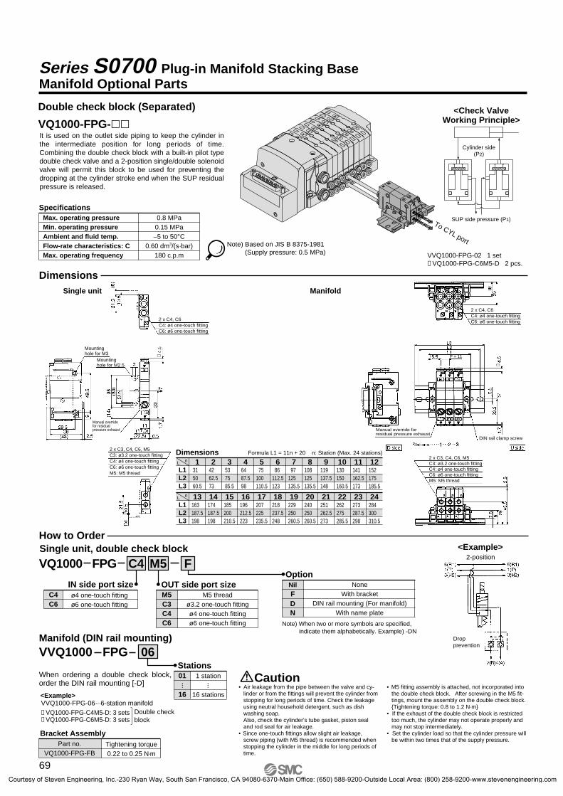
<Check ValveWorking Principle>
VVQ1000-FPG-02 1 set∗ VQ1000-FPG-C6M5-D 2 pcs.
L1L2L3
31 50 60.5
1 2 3 4 5 6 7 8 9 10 11 1242 62.573
53 75 85.5
64 87.598
75 100 110.5
86 112.5123
97 125 135.5
108 125 135.5
119 137.5148
130 150 160.5
141 162.5173
152 175 185.5
nL
L1L2L3
163 187.5198
13 14 15 16 17 18 19 20 21 22 23 24174 187.5198
185 200 210.5
196 212.5223
207 225 235.5
218 237.5248
229 250 260.5
240 250 260.5
251 262.5273
262 275 285.5
273 287.5298
284 300 310.5
nL
VQ1000 FPG FM5C4
IN side port size OUT side port sizeOptionNil
DN
NoneWith bracket
DIN rail mounting (For manifold)With name plate
M5C3C4C6
M5 threadø3.2 one-touch fittingø4 one-touch fittingø6 one-touch fitting
C4C6
ø4 one-touch fitting ø6 one-touch fitting
Manifold (DIN rail mounting)
VVQ1000 FPG 06
F
SpecificationsMax. operating pressureMin. operating pressureAmbient and fluid temp.Flow-rate characteristics: CMax. operating frequency
0.8 MPa0.15 MPa–5 to 50°C
0.60 dm3/(s·bar)180 c.p.m
To CYL port
Series S0700 Plug-in Manifold Stacking BaseManifold Optional Parts
Note) When two or more symbols are specified, indicate them alphabetically. Example) -DN
Double check block (Separated)
VQ1000-FPG-��It is used on the outlet side piping to keep the cylinder in the intermediate position for long periods of time. Combining the double check block with a built-in pilot type double check valve and a 2-position single/double solenoid valve will permit this block to be used for preventing the dropping at the cylinder stroke end when the SUP residual pressure is released.
Note) Based on JIS B 8375-1981(Supply pressure: 0.5 MPa)
DimensionsSingle unit Manifold
Dimensions Formula L1 = 11n + 20 n: Station (Max. 24 stations)
How to OrderSingle unit, double check block
VVQ1000-FPG-06···6-station manifold∗ VQ1000-FPG-C4M5-D: 3 sets∗ VQ1000-FPG-C6M5-D: 3 sets
<Example>
Double check block
When ordering a double check block, order the DIN rail mounting [-D]
Stations01
16
1 station
16 stations
··· ···
Part no.VQ1000-FPG-FB
Tightening torque0.22 to 0.25 N·m
Bracket Assembly
Caution• Air leakage from the pipe between the valve and cy-
linder or from the fittings will prevent the cylinder from stopping for long periods of time. Check the leakage using neutral household detergent, such as dish washing soap. Also, check the cylinder’s tube gasket, piston seal and rod seal for air leakage.
• Since one-touch fittings allow slight air leakage, screw piping (with M5 thread) is recommended when stopping the cylinder in the middle for long periods of time.
• M5 fitting assembly is attached, not incorporated into the double check block. After screwing in the M5 fit-tings, mount the assembly on the double check block. {Tightening torque: 0.8 to 1.2 N·m}
• If the exhaust of the double check block is restricted too much, the cylinder may not operate properly and may not stop intermediately.
• Set the cylinder load so that the cylinder pressure will be within two times that of the supply pressure.
(P2)
SUP side pressure (P1)
Cylinder side
Dropprevention
<Example>2-position
Mountinghole for M3
DIN rail clamp screw
P = 11Mountinghole for M2.5
Manual override for residual pressure exhaust Manual override for
residual pressure exhaust
2 x C4, C6C4: ø4 one-touch fittingC6: ø6 one-touch fitting
2 x C4, C6C4: ø4 one-touch fittingC6: ø6 one-touch fitting
2 x C3, C4, C6, M5C3: ø3.2 one-touch fittingC4: ø4 one-touch fittingC6: ø6 one-touch fittingM5: M5 thread
2 x C3, C4, C6, M5C3: ø3.2 one-touch fittingC4: ø4 one-touch fittingC6: ø6 one-touch fittingM5: M5 thread
69
S0700-B.qxd 09.4.24 4:38 PM Page 69
Courtesy of Steven Engineering, Inc.-230 Ryan Way, South San Francisco, CA 94080-6370-Main Office: (650) 588-9200-Outside Local Area: (800) 258-9200-www.stevenengineering.com

Double: S0720
Dual 3-Port: S07B0A
C
i
t
i
t
i r e w q y
u
r e w q y
u
r e w q y
t u
r
r
5(R1)
4(A)
1(P)
2(B)
3(R2)
5(R1)
4(A)
1(P)
2(B)
3(R2)
5(R1)
4(A)
1(P)
2(B)
3(R2)
S07C04
(A)2
(B)
5(R1) 1
(P)
3(R2)
N.C. + N.O.
S07B04
(A)2
(B)
5(R1) 1
(P)
3(R2)
N.O. + N.O.
S07A04
(A)2
(B)
5(R1) 1
(P)
3(R2)
N.C. + N.C.
S0720(A)4
(B)2
5(R1)
1(P)
3(R2)
S0710(A)4
(B)2
5(R1)
1(P)
3(R2)
Series S0700 Plug-in Manifold Stacking BaseConstruction
Single: S0710
Note) Please consult with SMC for pilot valve replacement.
Component Parts
1
2
3
4
5
6
7
8
DescriptionNo. Material
Body
Spool
Piston
Manual override
Adapter plate
Cover
Interface gasket
Pilot valve assembly Note)
Zinc die-casted
Aluminum
Resin
Resin
Resin
Resin
HNBR
—
Plu
g-i
n M
anif
old
Sta
ckin
g B
ase
Slim
Co
mp
act
Plu
g-i
n M
anif
old
Bar
Bas
eP
lug
Lead
Man
ifo
ldB
ar B
ase
Plu
g Le
ad
Sin
gle
Un
it
70
S0700-B.qxd 09.4.24 4:38 PM Page 70
Courtesy of Steven Engineering, Inc.-230 Ryan Way, South San Francisco, CA 94080-6370-Main Office: (650) 588-9200-Outside Local Area: (800) 258-9200-www.stevenengineering.com

EX500
series
!2
!3
!4
we
r
!0
!1
!5
!9 !8
@0
!6
@2
@1
!7
q
Series S0700 Plug-in Manifold
Exploded View of Manifold
tiu
o
y
Manifold block assemblyD-side end plate assembly U-side end plate assemblyHousing assembly and SI unit
S k
itF
kit
P/J
kit
T k
itL
kit
M k
itE
X50
0E
X25
0E
X60
0
71
S0700-B.qxd 09.4.24 4:38 PM Page 71
Courtesy of Steven Engineering, Inc.-230 Ryan Way, South San Francisco, CA 94080-6370-Main Office: (650) 588-9200-Outside Local Area: (800) 258-9200-www.stevenengineering.com

Description NotePart no.
EX500-Q001EX500-Q101EX250-SDN1EX250-SPR1EX250-SMJ2EX250-SAS3EX250-SAS5EX250-SAS7EX250-SAS9EX250-SCA1AEX250-SCN1EX250-SEN1EX250-IE1EX250-IE2EX250-IE3EX250-EA1EX250-EA2
No.
DeviceNet™, PROFIBUS DP, CC-Link, EtherNet/IP™ (+COM.)
DeviceNet™, PROFIBUS DP, CC-Link, EtherNet/IP™ (–COM.)
DeviceNet™ (–COM.)
PROFIBUS DP (–COM.)
CC-Link (+COM.)
AS-Interface 31 slave, 8 in/8 out, 2 power supply systems (–COM.)
AS-Interface 31 slave, 4 in/4 out, 2 power supply systems (–COM.)
AS-Interface 31 slave, 8 in/8 out, 1 power supply systems (–COM.)
AS-Interface 31 slave, 4 in/4 out, 1 power supply systems (–COM.)
CANopen (–COM.)
ControlNet™ (–COM.)
EtherNet/IP™
M12 2 inputs
M12 4 inputs
M8 4 inputs
Standard
For DIN rail mounting
F kit 25 pins
P kit 26 pins
P kit 20 pins
J kit 20 pins
T kit
L kit Lead wire length 0.6 m
L kit Lead wire length 1.5 m
L kit Lead wire length 3.0 m
M kit 26 pins
SI unitq
SI unitw
Input blocke
End plate assemblyr
D-sub connector housing assembly!0
Terminal block box housing assembly!2
Lead wire housing assembly!3
Circular connector housing assembly!4
Flat ribbon cable housing assembly
Flat ribbon cable housing assemblyFlat ribbon cable PC wiring system compatible
!1
VVQC1000-F25-1VVQC1000-P26-1VVQC1000-P20-1
VVQC1000-J20-1
VVQC1000-T0-1VVQC1000-L25-0-1VVQC1000-L25-1-1VVQC1000-L25-2-1VVQC1000-M26-1
DeviceNet™ PNP (–COM.)
DeviceNet™ NPN (+COM.)
CC-Link PNP (–COM.)
CC-Link NPN (+COM.)
PROFIBUS DP PNP (–COM.)
PROFIBUS DP NPN (+COM.)
NPN input M12 connector 5 pins (4 pcs.) 8 inputs
PNP input M12 connector 5 pins (4 pcs.) 8 inputs
NPN input M8 connector 3 pins (8 pcs.) 8 inputs
NPN input M8 connector 3 pins (8 pcs.) 8 inputs, with broken wire detection function
PNP input M8 connector 3 pins (8 pcs.) 8 inputs
PNP input M8 connector 3 pins (8 pcs.) 8 inputs, with broken wire detection function
NPN input M12 connector 5 pins (8 pcs.) 16 inputs
PNP input M12 connector 5 pins (8 pcs.) 16 inputs
NPN input M12 connector 5 pins (4 pcs.) 8 inputs
PNP input M12 connector 5 pins (4 pcs.) 8 inputs
M12 connector 5 pins (2 pcs) 2-channel input
M12 connector 5 pins Max. supply current 2A
M12 connector 5 pins Max. supply current 2A, with DIN rail mounting bracket
7/8 inch connector 5 pins Max. supply current 8A
7/8 inch connector 5 pins Max. supply current 8A, with DIN rail mounting bracket
EX600-SDN1EX600-SDN2EX600-SMJ1EX600-SMJ2EX600-SPR1EX600-SPR2EX600-DXNBEX600-DXPBEX600-DXNCEX600-DXNC1EX600-DXPCEX600-DXPC1EX600-DXNDEX600-DXPDEX600-DYNBEX600-DYPBEX600-AXAEX600-ED2EX600-ED2-2EX600-ED3EX600-ED3-2
t
y
u
i
o
SI unit
Digital input unit
Digital output unit
Analog input unit
End plate
Manifold Assembly Part No.
<Housing Assembly and SI Unit, Input Block>
Plu
g-i
n M
anif
old
Sta
ckin
g B
ase
Slim
Co
mp
act
Plu
g-i
n M
anif
old
Bar
Bas
eP
lug
Lead
Man
ifo
ldB
ar B
ase
Plu
g Le
ad
Sin
gle
Un
it
72
Plug-in Manifold Series S0700
S0700-B.qxd 09.4.24 4:38 PM Page 72
Courtesy of Steven Engineering, Inc.-230 Ryan Way, South San Francisco, CA 94080-6370-Main Office: (650) 588-9200-Outside Local Area: (800) 258-9200-www.stevenengineering.com

Tie-rod for station additions
U-side end plate
Hexagon boltTightening torque: 0.85 to 0.95 N �m
Convexpart
Socket housing
Junction cover
Round type terminal
Tightening torque: 0.25 to 0.35 N �m
Convex partRed
White Black
<Replacement Parts for Manifold Block>
Option
!5 D-side end plate assembly part no.
SS0700
!7 U-side end plate assembly part no.SS0700 2A 2
!8 Fitting assembly part no.
VVQ0000 50A
3A 1!6 Manifold block assembly Tie-rod (2 pcs.) and lead wire assembly for extensions are attached.
SS0700 1A
Replacement PartsNo.
!9@0@1
Part no.Description
Gasket
Clip
Tie-rod assembly
Q’ty
10 Note 1)
10 Note 1)
2 Note 2)
SS0700-80A-2SS0700-80A-4SS0700-TR-�
<Replacement Parts for Valve>
Note) Above part number consists of 10 units. Each unit has one gasket and two screws.
Replacement PartsNo.
@2
Part no.Description
Gasket, Screw
Q’ty
10S0700-GS-5
PD 05C8 C3
Port size
Wiring specifications
Port size
Stations
Port size
Manifold Assembly Part No.
Port sizeø8 one-touch fittingø5/16" one-touch fitting
SymbolC8N9
SymbolNilRS
SpecificationsCommon EXHExternal pilotDirect EXH outlet with built-in silencer
Note) When both options are specified, indicate as “-RS”.
SpecificationsDouble wiringSingle wiringNone
SymbolPDPSP0
Stations2 stations
24 stations
Symbol02
24
··· ···
Port sizeø2 one-touch fittingø3.2 one-touch fittingø4 one-touch fittingø1/8" one-touch fittingø5/32" one-touch fittingWithout one-touch fitting
SymbolC2C3C4N1N3C0
OptionSymbol
NilB
SpecificationsNoneWith back pressure check valve
Applicable tubingApplicable tubing ø2Applicable tubing ø3Applicable tubing ø4Applicable tubing ø1/8"Applicable tubing ø5/32"
SymbolC2C3C4N1N3Note 1) Purchasing order is available in units
of 10 pieces.Note 2) For one-touch fittings replacement,
refer to “Specific Product Precautions.”
Note 1) 1 set includes 10 pieces.Note 2) 1 set includes 2 pieces. Please order when
eliminating manifold stations. When adding stations, tie-rods are attached to the manifold block assembly. Therefore, it is not necessary to order.�: Stations 02 to 24
How to Add Manifold Stations (Plug-in Type / Lead Wire Connection Type)
What to orderManifold block assembly (Refer to the above !6.)
Steps for adding stationsLoosen hexagon bolts from the end plate at the U-side and re-move the end plate.Connect the tie rod for increasing the station number, open the junction cover, mount the manifold block assembly and U-side end plate and tighten them by hexagon bolts. (Tightening torque: 0.85 to 0.95 N �m)
Connect the round type terminal of red lead wire to the common terminal inside the junction cover.
Take out the socket housing and connect the black and white lead wires. The connection layout is common to all kits.
2A
3A
4A
13A
1B
2B
3B
4B
5B
6B
7B
8B
9B
10B
11B
12B
13B
5A
6A
7A
8A
9A
12A
11A
10A
COM. Red Red COM.
Black Station 1 SOL.ASOL.A Station 2 Black
SOL.B Station 3 White
SOL.B Station 4 White
Black Station 3 SOL.A
Black Station 4 SOL.A
Black Station 5 SOL.ASOL.B Station 5 White
Black Station 6 SOL.A
1A
Terminal no.
73
Series S0700
S0700-B.qxd 09.4.24 4:38 PM Page 73
Courtesy of Steven Engineering, Inc.-230 Ryan Way, South San Francisco, CA 94080-6370-Main Office: (650) 588-9200-Outside Local Area: (800) 258-9200-www.stevenengineering.com