manned maneuvering unit cr- mission … the manned maneuvering unit (mmu) mission definition study...
TRANSCRIPT

MANNED MANEUVERING UNIT NASA CR-
MISSION DEFINITION STUDY
FINAL REPORT
S -. 7
VOLUE fa
MMU ANCILLARY SUPPORT EQUIPMENTAND ATTACHMENT CONCEPTS
(NASA-CR-141633) MANNED MANEUVERING UNIT N75-17108MISSION DEFINITION STUDY. VOLUME 3: MMUANCILLARY SUPPORT EQUIPMENT AND ATTACHMENT NAS9-13790CONCEPTS Final Report (URS/Matrix Co., Unclas MOD. NO. ISHouston, Tex.) 129 p HC $5.75 CSCL 06K G3/54 10225
LIFE and ENVIRONMENTAL SCIENCES DIVISIONSUITE 103 1275 SPACE ARK DRIVE. HOUSTON. TEXAS 77058 17131 3333242 JANUARY 1975
https://ntrs.nasa.gov/search.jsp?R=19750009036 2018-07-06T23:44:46+00:00Z

MANNED MANEUVERING UNIT
MISSION DEFINITION STUDY
FINAL REPORTCONTRACT NAS 9-13790
(MODIFICATION NO.1S)
VOLUME III:
MMU ANCILLARY SUPPORT EQUIPMENT
AND
ATTACHMENT CONCEPTS
PREPARED FOR:
NATIONAL AERONAUTICS AND SPACE ADMINISTRATION
LYNDON B. JOHNSON SPACE CENTER
HOUSTON, TEXAS 77058
URS CORPORATION
URS/MATRIX COMPANY
LIFE AND ENVIRONMENTAL SCIENCES DIVISION
1275 SPACE PARK DRIVE
HOUSTON, TEXAS 77058
JANUARY 1975
FOREWORD
The Manned Maneuvering Unit (MMU) Mission Definition Study was conducted
as the result of an Engineering Change Request to Contract NAS 9-13790
entitled "Development of an:EVA Systems Cost Model." The study was sponsored
by the Bio-Engineering Division, Life Sciences Office of NASA Headquarters
under the responsibility of Dr. Stanley Deutsch, Director. The work was
managed under the technical direction of Mr. David C. Schultz, Chief of the
Procedures Branch, Crew Training and Procedures Division, Flight Operations
Directorate at the Lyndon B. Johnson Space Center, Houston, Texas. The Con-
tracting Officer was Mr. James W. Wilson/BC76, Program Procurement Division.
The major objectives of the study were the following: (1) identify MMU
applications which would supplement Space Shuttle safety and effectiveness;
(2) define general MMU performance and control requirements to satisfy can-
didate Shuttle applications; (3) develop concepts for attaching MMUs to various
worksites and equipment; and (4) identify requirements and develop concepts
for MMU ancillary equipment. The study was performed over a seven-month period
beginning June 1974.
The final report for the contract is presented in the following three
volumes:
Volume I: MMU Applications Analyses and Performance Requirements
Volume II: Appendices to the MMU Applications Analyses
Volume III: MMU Ancillary Support Equipment and Attachment Concepts
This report (Volume III) provides the findings of the conceptual design
milestones of the contract.
i

ACKNOWLEDGMENTS
The NASA Technical Monitor for this study was Mr. David C. Schultz, Chief,
Procedures Branch/CG2, Crew Training and Procedures Division, Flight Operations
Directorate, Johnson Space Center, Houston, Texas. Contract monitoring assis-
tance was provided by Mr. Louis V. Ramon in the Experiments Procedures Section
of the Crew Training and Procedures Division. Appreciation is expressed to Dr.
Stanley Oeutsch, Director, Bioengineering Division, Office of Life Sciences,
NASA Headquarters, for his efforts in arranging for the conduct of the study.
Valuable assistance in obtaining quantitative data and technical infor-
mation was supplied by personnel within the NASA Johnson Space Center. Special
appreciation is due Comdr. Bruce McCandless II/CB, Maj. Charles E. Whitsett/
ZRI, Mr. William L. Burton, Jr./EC6, and Mr. Louis V. Ramon/CG2.
The contractor Principal Investigator for the study was Mr. Nelson E.
Brown, Division Director, Life and Environmental Sciences Division, URS/Matrix
Company, URS Corporation. Principal contributors within the URS/Matrix
Company were Mr. Billy K. Richard, Mr. Edward L. Saenger, Mr. G. Lloyd Philpot,
Mr. Kem B. Robertson III, and Mrs. Betty K. Bielat.
ii

Il.0l l I II 1 I
TABLE OF CONTENTS
PAGE
Foreword .. ........... . . .. . . . .
Acknowledgments ................... ......... . ii
List of Figures . . . . . . . . . . . . . . . . . . . . . . . . . . . . v
Acronyms and Abbreviations ................... .... ix
1.0 Introduction . . . . . . . . . . . . . . . . . . . . . . . . . . . 1-
1.1 Study Objectives--Conceptual Designs . ............ 1-1
1.2 Volumes I and II Overview . ................. 1-2
1.3 MMU-Orbital Systems Interfaces . ............... 1-3
1.4 Orbital Systems Support Requirements . ............ 1-6
2.0 MMU-EVA Shuttle Charter and Concept Definition . ......... 2-1
2.1 MMU Orbital Requirements Summary . . . . . . . . . . . 2-1
2.2 Maneuvering Unit Configuration Concepts . .......... 2-4
2.2.1 Existing MMU Units and Concepts . ........... 2-4
Astronaut Maneuvering Unit (AMU) . ........ . . 2-4
Automatically Stabilized Maneuvering Unit (ASMU) . . 2-4
Space Shuttle Maneuvering Unit Concepts . ....... 2-7
2.2.2 Crew/MMU Reach and Visibility Analysis . ....... 2-7
2.2.3 Study Developed Concepts ..... ........... 2-22
Unitary Designs . .................. . 2-22
Modular Designs . .................. . 2-26
3.0 MMU Ancillary Subsystem Concepts . ................ 3-1
3.1 Orbital Systems Interfaces . ................. 3-1
3.1.1 MMU Restraint Interfaces . .............. 3-2
3.1.2 MMU-to-Worksite Interface (Orbiter and Payloads) . . 3-14
Prepared Worksites . .. .............. . 3-19
Unprepared Worksites . ...... ... ....... . 3-26
3.1.3 MMU-to-Personnel Rescue System (PRS) Interface .... 3-38
3.1.4 MMU-to-Suited Crewman Interface . ........... 3-47
3.1.5 MMU-to-MMU Interface . ................ 3-47
iii

TABLE OF CONTENTS (continued)
PAGE
3.2 MMU Ancillary Subsystem Interfaces . ......... . . . 3-50
3.2.1 Visibility and Illumination Equipment Interfaces . 3-54
3.2.2 Tool Stowage Interfaces . ......... . . . . . 3-57
3.2.3 Module Replacement Concepts. . .......... . 3-62
3.2.4 Consumables Resupply Concepts . .......... . 3-67
3.2.5 Data Acquisition Concepts . .......... . . . 3-67
3.2.6 Miscellaneous Equipment Attachment/RetrievalConcepts . . . . . . . . . . . . . . . . . . . . . . 3-72
4.0 General MMU Conclusions and Recommendations . ..... . .. .. . 4-1
Conclusions . . . . . . . ... . . . . . . . . . . . . . . 4-1
Recommendations ........ . . . .. . . . . . ...... . 4-1
iv

LIST OF FIGURES
FIGURE PAGE
1.1 Study Interrelationships . . . .. . . . . . . . . . . . . . . . 1-4
1.2 MMU-to-Orbital Systems Interface Requirements .... .. . . 1-5
1.3 Major Elements/Requirements of EVA Man-System ...... . . . 1-7
2.1 Gemini Astronaut Maneuvering Unit . ....... . . . . . . ... 2-5
2.2 Skylab Automatically Stabilized Maneuvering Unit (ASMU) . . . 2-6
2.3 NASA MMU Configuration Concept . ......... . . . . . . ... 2-8
2.4 Hot Gas Module for MMU Concept ..... . . ... . . . . . . . 2-9
2.5 MMU with Integrated EMU (Preliminary Concepts) ..... . .... . 2-10
2.6 Basic MMU Configuration for Study Analysis . ......... . 2-11
2.7 MMU Soft Mockup--Used for Reach and Visibility Studies .... . 2-12
2.8 MMU Soft Mockup--Front Views .. ..... .. .... . . . . . . . 2-13
2.9 MMU Soft Mockup--Side Views .. . . . . . . . . . .. . . . . . 2-14
2.10 Crewman-MMU Preliminary Reach Envelope ... . .. .. .. . . . 2-15
2.11 Crewman-MMU Tactile Reach Envelope ......... . . . . . ... 2-16
2.12 Crewman-MMU Direct Visual Equipment Recommended Locations . . . 2-17
2.13 Recommended Locations for MMU C/D Panels and Support Hardware . 2-18
2.14 Recommended Locations for MMU Cargo Attachment . ....... . 2-19
2.15 Recommended Locations for MMU Positioning Relative to Worksites. 2-20
2.16 Crewman Reach and Visibility--Basic MMU Configuration ..... 2-21
2.17 MMU Configuration Concept--Unitized Design with RemovableControl Arms . . . . . . . . . . . . . . . . . . . . . . . . . . 2-23
2.18 MMU Control Arm Adjustment Concept . ........ . ...... . . 2-24
2.19 MMU Configuration Concept--Unitized Design with IntegratedControls . . . . . . . . . . . . . . . . . . . . . . . . . . . . 2-25
2.20 MMU Supplementary Crew Restraint--Concept 1 . ....... . . 2-27
2.21 MMU Supplementary Crew Restraint--Concept 2 . ....... . . 2-28
2.22 MMU Configuration Concept--Modular Design . .......... 2-29
3.1 MMU-to-Orbiter Interface--Launch, Reentry and ServicingRestraint (Overcenter Side Locks and Pins) . . . . . . . . . . . 3-4
3.2 MMU-to-Orbiter Interface--Launch, Reentry and ServicingRestraint (Ball and Socket Plus Pins) . . . . . . . . . . . . . 3-5
v

LIST OF FIGURES (continued)
FIGURE PAGE
3.3 MMU-to-ALSA and Orbiter Restraint Attachment Concept(Slider-Type Interfaces) . ............. . . . . . ... 3-6
3.4 MMU Donning Station Concept (Fixed) . ............. 3-8
3.5 Removable Launch/Reentry MMU Attachment Concept . ....... 3-9
3.6 Bungee Restraint for MMU Donning/Checkout Concept . ...... 3-10
3.7 Tension Bar Restraint for MMU Donning/Checkout Concept .... . 3-10
3.8 MMU "Swing-Out" Servicing Attachment Concept . ......... 3-12
3.9 MMU Donning Station Concept--Interface with Orbiter Side Hatch . 3-13
3.10 Modular MMU Donning Station Concept . ............. 3-15
3.11 MMU Application to Large Geodetic Space Structure Assembly . . . 3-16
3.12 MMU Application to Automated Payload--Repair at PreparedWorksite . . . . . . . . . . . . . . . . . . . . . . . . . . . . 3-17
3.13 MMU Application to Large Antenna System--Repair at UnpreparedWorksite . . . . . . . . . . . . . . . . . . . . . . . . . . . . 3-18
3.14 Concept for MMU Attachment to Prepared Site ... ....... 3-20
3.15 Tripod Foot Restraint Concept . .............. . . 3-21
3.16 Tripod Workstation Concept--Modular Equipment . ..... . . . 3-22
3.17 Tripod Workstation Folding Sequence and Positioning . ..... 3-23
3.18 Foot Restraint Attachment Concept--Prepared Worksite(Ball and Sockets) . . . . . . . . . . . . . .. . . . . . . . . 3-24
3.19 Portable Workstation Concept--Modular Equipment . ....... 3-25
3.20 Typical Attachment Brackets from Previous Space Programs . . . . 3-27
3.21 Universal "C" Clamp Attachment Device Concept . ........ 3-28
3.22 Universal Clamp Concept for MMU Restraint--Unprepared Worksite . 3-29
3.23 Universal MMU Clamp Details ............... . . . . 3-31
3.24 Pneumatic MMU Clamp Concept . .. .......... . . . ..... 3-32
3.25 Grapplers for Restraining MMU to an Unprepared Worksite . . . . 3-33
3.26 Side-Mounted Device for Attaching MMU to Unprepared Worksite . 3-33
3.27 Universal Clamp-to-Portable Workstation Interface . ...... 3-34
3.28 Workstation-to-Angle/Plate Attachment Concept . ....... . 3-35
3.29 Foot Restraint Concept--Unprepared Site (Ball and Socketwith Adhesive Pads) . . . . . . . . . . . . . . . . . . . . . . 3-37
vi
LIST OF FIGURES (continued)
FIGURE PAGE
3.30 Adhesive Pad Workstation Attachment Concept . ..... . ... . . 3-39
3.31 TPS Repair from Portable Workstation Attached to TPS . ..... 3-40
3.32 MMU Adhesive Attachment to Flat Surfaces--Unprepared Worksite . 3-41
3.33 Adjustable Tether Concept--Shuttle Orbiter Restraint . ..... 3-42
3.34 PRS-to-MMU Attachment Interface--Tether Concept ..... . . . . 3-44
3.35 Personnel Rescue System-to-MMU Interface--Grappler Arm Concept . 3-45
3.36 Mechanical PRS Grappler Device Concept . ....... . . . . . 3-46
3.37 MMU-to-Spacesuited Crewman Interface--Tether Concept . ..... 3-48
3.38 MMU-to-MMU Attachment--Mechanical Concept . . . ..... ..... . 3-49
3.39 MMU-to-MMU Capture/Restraint Concept--Grappler Arm Concept . . . 3-51
3.40 Space Qualified Attachment/Fastening Equipment Illustrations . 3-52
3.41 Ancillary MMU Subsystems for Visual Support--Location andAttachments . . . . . . . . . . . . . . . . . . . . . . . . 3-55
3.42 Remote Control Ancillary Equipment Mounting Concept . ...... 3-56
3.43 Tool Kit Attachment Location--Adjustable Concept . ........ 3-58
3.44 Tool Kit/Support Subsystem Concept . ..... .. . . . . . . . 3-59
3.45 Tool Pouch and Attachment Concepts . .......... ... . . 3-60
3.46 Tool Pouch Concept--Configuration Details . ........ . . . 3-61
3.47 MMU/EVA Support Equipment "Stacking" Concept . ....... . . 3-63
3.48 Ancillary Support Equipment Restraint Pallet Concept . ..... 3-64
3.49 Ancillary Equipment Stowage Bar Concept . ........ . . . . 3-65
3.50 Orbital Systems Servicing Module Attachment Concept . ...... 3-66
3.51 Consumable Resupply System Concept . ..... . . . . . . . . . 3-68
3.52 MMU Auxiliary Propellant Stowage Concept . ........ . . . 3-69
3.53 Data Acquisition Concept--Remote Video Inspection/Surveillance . 3-70
3.54 Data Acquisition Equipment Concept--Wake Detection andMeasurement . . . . . . . . . . . . . . . . . . . 3-71
3.55 Ancillary Equipment Candidate Locations ....... . . . . . ... 3-73
3.56 Equipment Stowage Bar Concept ........ . . . . . . . . . ... 3-73
3.57 Computerized Checklist Display Concept . ..... .. . . . . . 3-75
vii

LIST OF FIGURES (continued)
FIGURE PAGE
3.58 Procedures Checklist Concepts--Automatic/Manual . ....... 3-76
3.59 Extendible Boom System Concept . ..... . . .... ..... . 3-77
3.60 Cargo Capture/Transfer Net Concept . ........... . . 3-79
viii
Iuri I -_ _ _ _
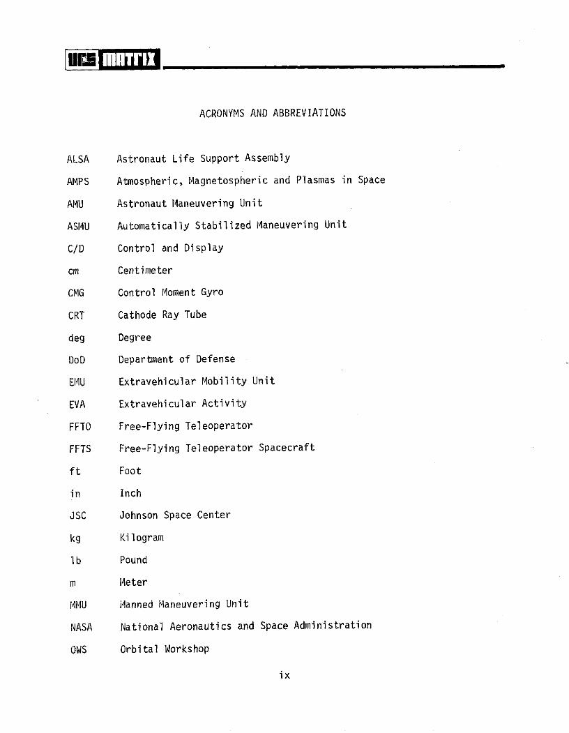
ACRONYMS AND ABBREVIATIONS
ALSA Astronaut Life Support Assembly
AMPS Atmospheric, Magnetospheric and Plasmas in Space
AMU Astronaut Maneuvering Unit
ASMU Automatically Stabilized Maneuvering Unit
C/D Control and Display
cm Centimeter
CMG Control Moment Gyro
CRT Cathode Ray Tube
deg Degree
DoD Department of Defense
EMU Extravehicular Mobility Unit
EVA Extravehicular Activity
FFTO Free-Flying Teleoperator
FFTS Free-Flying Teleoperator Spacecraft
ft Foot
in Inch
JSC Johnson Space Center
kg Kilogram
lb Pound
m Meter
MMU Manned Maneuvering Unit
NASA National Aeronautics and Space Administration
OWS Orbital Workshop
ix

ACRONYMS AND ABBREVIATIONS (continued)
PLSS Portable Life Support System
PRS Personnel Rescue System
QD Quick Disconnect
RMS Remote Manipulator System
sec Second
TPS Thermal Protection System
x
1.0 INTRODUCTION
The Manned Maneuvering Unit (MMU) mission definition study primary objec-
tives were to identify and describe candidate applications of MMUs to the Space
Shuttle Program and to develop conceptual designs of MMU ancillary support
equipment and attachment hardware/interfaces. The MMU applications analyses
included studies of the Shuttle Orbiter, Orbiter subsystems, and both Sortie
and Automated Payloads under consideration in mid-1974 for subsequent flights.
Based on the stronger practicable MMU applications, general performance and
control requirements for Shuttle supporting maneuvering units were defined.
The results of the MMU applications analyses and the general MMU performance
and control requirements identified are presented in Volume I of this final
report with supporting material contained in Volume II, "Appendices to the MMU
Applications Analyses."
To describe a versatile utility-type maneuvering unit, conceptual designs
of MMU support subsystems and ancillary equipment were prepared. Concepts for
attaching and securing the MMU-crewman to various vehicles, structural con-
figurations, and rescue systems were developed. Concepts for incorporating
ancillary hardware, such as cargo attachment mechanisms, cameras, lights, tools,
tethers and safety provisions, were addressed. The conceptual designs are
presented in this volume of the final report. As a result of the MMU appli-
cations analyses, it was concluded that an MMU capability could be the decisive
element in returning a Shuttle Orbiter and its crew to safety and also an
economical operational tool for numerous Orbiter and payload applications.
1.1 STUDY OBJECTIVES--CONCEPTUAL DESIGNS
The objectives specified for the conceptual design phase of the MMU study
were:
* Develop concepts for the attachment interface between the MMU and
other major orbital elements of the Space Shuttle Program: Attachment
and stabilization concepts encompassed interfacing the MMU-crewman
1-1
combination to the Shuttle Orbiter, free-flying payloads, personnel
rescue systems (PRS) and other MMUs. Attaching the MMU to the
Shuttle Orbiter for launch, servicing and reentry were included in
the conceptual designs.
* Develop concepts for ancillary equipment required to support potential
MMU missions and provide preliminary concepts for the attachment inter-
face between the MMU and the ancillary equipment: Supporting subsystems
and equipment, such as auxiliary lighting, cameras, tools, tethering
devices, cargo attachment mechanisms, etc. were considered during con-
ceptual development. Conceptual design of modular, add-on ancillary
equipment with standardized interfaces received primary consideration.
1.2 VOLUMES I AND II OVERVIEW
The MMU mission definition study final report is contained in three volumes.
Volumes I and II report the findings of an MMU Shuttle applications analysis and
defines preliminary MMU performance and control requirements. The conceptual
designs of MMU supporting subsystems were derived based on the potential appli-
cations defined in Volumes I and II. These volumes should be reviewed by the
reader prior to assessing the concepts presented in this volume. A brief over-
view of Volume I and II contents are provided below.
Volume I: Volume I, "MMU Applications Analyses and Performance Require-
ments," presents the findings of a detailed and systematic study of the Orbiter
exterior mechanical and passive subsystems considered critical to loss of life
or vehicle while on-orbit or during reentry. Numerous MMU Shuttle applications
identified by the study are based on performing corrective action following a
specific failure. However, many of the candidate MMU applications defined may
allow more effective and economical-operational missions than with other proposed
systems. Many MMU applications now considered as candidates may become the only
method to satisfactorily accomplish critical missions when the capabilities of
other systems (e.g., remote manipulator system (RMS), free-flying teleoperator
spacecraft (FFTS), automation) are completely defined. The stronger MMU appli-
cations to the Shuttle Orbiter were defined as:
1-2

* Inspection of the Orbiter exterior to determine reentry status
* Repair of,0Orbiter exterior subsystems to ensure safe reentry
* Crewman rescue from a disabled, unstable Orbiter.
The analyses also considered the Shuttle payloads from a standpoint of:
(1) restoring the payload to operational status following a malfunction; (2)
retrieval of payload data and equipment from scientific and economic aspects;
and (3) assistance in deploying/retrieving satellites. Eighty-three (83)
payloads within the automated disciplines and 96 payloads within the sortie
disciplines (including revisits) were reviewed for potential MMU applications.
DoD payloads were not included in the analyses.
In considering the complexity of payloads relative to mechanical, electrical/
electronic, optical, and pneumatic systems, few could be totally eliminated that
would not benefit from EVA/MMU capabilities should malfunctions occur, particu-
larly: (1) those payloads requiring aid in deployment/retrieval; (2) payloads
with equipment extending beyond the payload bay door closure envelope; and (3)
contamination-sensitive and other payloads with potential advantages from on-
orbit servicing or refurbishment. The payloads analysis has resulted in a repre-
sentative set of potential MMU applications and typical tasks derived from both
the automated and sortie disciplines. The overall applications analyses pro-
vided the basis for developing general MMU performance and control requirements.
The interrelationship of the analyses to the total study is shown in Figure 1.1
Volume II: This volume presents the detailed supporting material and com-
putations for the MMU Applications Analysis and Performance Requirements
presented in Volume I. Volume II should be used in conjunction with the
other volumes of the final report if additional supporting information is
required.
1.3 MMU-ORBITAL SYSTEMS INTERFACES
The ancillary support equipment identified and the attachment conceptual
designs were provided to support MMU applications relative to the orbital
1-3

SHUTTLE ORBITERPAYLOAD BAY SUBSYSTEMS
SHUTTLE ORBITER R.... AALY~SEXTERIOR SUBSYSTEMS
CANDIDATE MMU SHUTTLE APPLICATIONSAUTOMATED PAYLOADS
SORTIE/SPACELAB PERFORMANCE AND CONTROL REQUIREMENTS
PAYLOADS MMU SUPPORT EQUIPMENT REQUIREMENTS
ASTRONAUT MANEUVERING MMU TO WORKSITE INTERFACE IDENTIFICATIONEQUIPMENT (SKYLAB)
MANNED MANEUVERING UNITCONCEPT DEFINITION
.cj 00. [MMU ANCILLARY EQUIPMENT BASIS FOR MMU
MMU ATI'ACHMENT INTERFACES > APPLICATIONON
SPACE SHUTTLE
AND
PRELIMINARYMMU DESIGN
FIGURE 1.1: Study Interrelationships REQUIREMENTS

systems and interfaces depicted in Figure 1.2. Interfacing the MMU to the Shuttle
ORBITAL SYSTEMS - MMU INTERFACES
.. .i
Personnel Suited Un- MannedRescue Crewman manned
Unpre- Prepared Systemspared Worksite
Launch/ Doff/Don, Worksite
Reentry Checkout/Service
FIGURE 1.2: MMU-to-Orbital Systems Interface Requirements
Orbiter for launch, on-orbit servicing and reentry was addressed in addition
to prepared and unprepared worksites. As shown in the figure, the MMU inter-
face requirements for prepared and unprepared worksites on the Orbiter are
similar to those of free-flying payloads. Various structural configurations
should be available at the unprepared worksites for MMU-crewman support equip-
ment attachment/stabilization. Prepared worksites will be configured (prior
to launch) to accept MMU-crewman equipment.
Conceptual designs of equipment for interfacing the MMU-crewman to per-
sonnel in a rescue situation was a viable requirement derived from the potential
MMU applications analyses. The MMU would require an attachment arrangement
with the Shuttle personnel rescue systems (PRS) and space suited crewmen in
a "free-space pickup" rescue mode. The MMU may also be utilized to transport
rescue MMUs to a disabled Orbiter for rescue operations or to rescue
another disabled MMU-crewman system.
1-5

1.4 ORBITAL SYSTEMS SUPPORT REQUIREMENTS
The orbital systems identified in the previous section require six major
elements (see Figure 1.3) to effect EVA man-system functions on-orbit. The
crewman (EVA astronaut), his protection (space suit), and life support systems
are obviously mandatory for manned operations outside the spacecraft. Of major
concern to this volume of the final report is the supporting equipment necessary
for adequately provisioning the EVA crewman to conduct local and remote oper-
ations in space. Initially, the EVA crewman and supporting cargo must be
provided with the capability to access the worksite (e.g., mobility aids)
followed by a sufficient worksite restraining system(s). After worksite
access, ancillary support subsystems may be required to perform specific
tasks.
The shaded entries shown in Figure 1.3 are addressed in subsequent sections
of this report with major emphasis on conceptual designs of ancillary add-on
equipment to support free-flying MMU operations.
1-6

EVA MAN-SYSTEM
CREWMAN CREW PROTECTION LIFE SUPPORT(SPACE SUIT) (ALSA)
SCONTRACT STUDY EFFORT
FIGURE 1.3: Major Elements/Requirements of EVA Man-System
2.0 MMU-EVA SHUTTLE CHARTER AND CONCEPT DEFINITION
The desired charter for the MMU-EVA crewman combination on the Space
Shuttle consists of the following: (1) provide a capability to access and
repair the Orbiter exterior to-ensure reentry status, (2) serve as a personnel
transporter in crewman rescue operations from a disabled Orbiter, (3) provide
MMUs in a utility category to support/service free-flying satellites (berthed
payloads also, if required), and (4) utilize the MMU capability to perform
experiments and collect space related data (e.g., inspection, stand-off photog-
raphy, deployment/retrieval, consumable resupply). Several credible Orbiter
contingencies categorized as Class I criticality (i.e., loss of life or vehicle)
are identified within the Shuttle verification and early operational flights
in which the MMU will be the only available system capable of performing tasks
outside the payload bay. The MMU may also prove the most effective means of
performing many tasks after all Orbiter-based support systems are operational.
The MMU applications to the payloads cannot, at the present, be designated as
the sole means of performing the candidate payload tasks. The full capabilities
of systems, such as the Orbiter-attached RMS and the FFTS, are not presently
defined. A premature assumption that these systems can perform all tasks,
planned or contingency, outside the payload bay could be excessively costly
to the payloads community in terms of loss of payload, data, inoperable
experiment, etc. if the worksites cannot be accessed. A Shuttle rendezvous,
capture, reentry and relaunch to acquire experiment data may be precluded by
on-orbit repair of experiment equipment via EVA-MMU.
2.1 MMU ORBITAL REQUIREMENTS SUMMARY
Based on Astronaut Maneuvering Equipment performance from the in-flight
Skylab M509 experiments and projected Space Shuttle MMU applications, the
National Aeronautics and Space Administration has been responsible for develop-
ing preliminary MMU requirements for future space missions. Volume I of this
study, "MMU Applications Analyses and Performance Requirements," reviewed
the Orbiter vehicle exterior subsystem and all mid-1974 proposed payloads for
required and candidate MMU applications. The major (preliminary) MMU performance
requirements and desirable characteristics/capabilities are:
2-1

Desirable Characteristics/Capabilities
* Versatile design to serve as a manned utility vehicle for numerous
space applications
* Noncontaminating system for sensitive payload servicing and
maintenance
* Precision maneuvering and station-keeping capability for unrestrained
tasks
* Quick turnaround time between MMU-EVA missions for maximum versatility
* Satellite rendezvous and spin rate duplication for satellite capture
and stabilization
• Cargo transportation capability between orbiting vehicles/satellites
* Rescue of free-floating equipment or personnel from a disabled vehicle
Interface Requirements (Excluding Orbiter Utilities)
* MMU to Shuttle payload bay for launch, on-orbit and reentry
* iMU to Astronaut Life Support Assembly (ALSA)
a MMU to Personnel Rescue System (PRS)
* M1MU to space suited astronaut
* MMU to another MMU
@ MMU/crewman to prepared worksites (Orbiter, payloads and satellites)
* MMU/crewman to unprepared worksites (Orbiter, payloads and satellites)
* Ancillary equipment and supporting hardware (fixed and portable) to the
MMU
Operational Considerations
* Fail-safe operation
* Mission duration of 6 hours
* One-man retrieval, stowage, service and don/doff on-orbit
2-2
* Self-contained system (utilizing the ALSA)
* Reasonable range capability from Orbiter
* Optional safety tether operation
* Spacecraft piloting logic
* Provisions for optional hot gas module (for additional delta V capability)
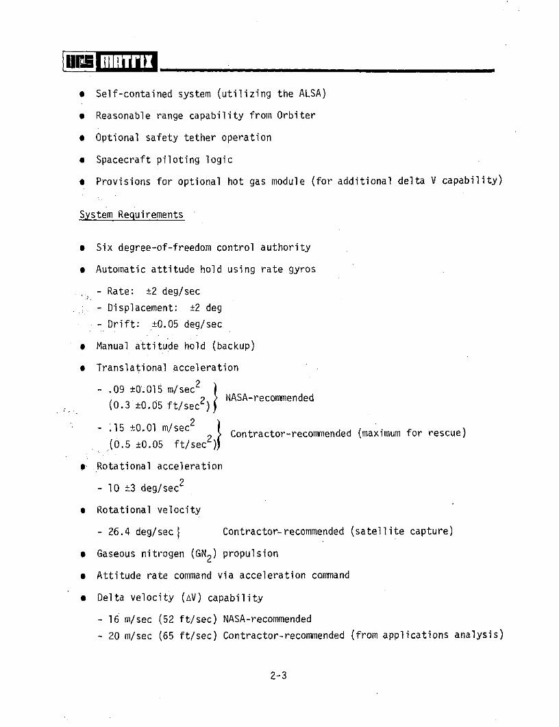
System Requirements
* Six degree-of-freedom control authority
* Automatic attitude hold using rate gyros
- Rate: ±2 deg/sec
. - Displacement: ±2 deg
- Drift: ±0.05 deg/sec
* Manual attitude hold (backup)
* Translational acceleration
- .09 ±O.05 m/sec2
(0.3 ±0.05 ft/sec 2 ) NASA-recommended
- .15 ±0.01 m/sec(0.5 ±0.05 ft/sec2 Contractor-recommended (maximum for rescue)(0.5 ±0.05 ft/sec2 )
* Rotational acceleration
- lO ±3 deg/sec2
* Rotational velocity
- 26.4 deg/sec Contractor-recommended (satellite capture)
* Gaseous nitrogen (GN2) propulsion
* Attitude rate command via acceleration command
a Delta velocity (AV) capability
- 16 m/sec (52 ft/sec) NASA-recommended
- 20 m/sec (65 ft/sec) Contractor-recommended (from applications analysis)
2-3

2.2 MANEUVERING UNIT CONFIGURATION CONCEPTS
Numerous maneuvering device concepts have been studied during the U.S.
space programs ranging from simple handheld maneuvering units to integrated
maneuvering life support systems. The most successful systems were the back
mounted units--the type being considered for the Shuttle Program. An overview
of the Gemini and Skylab (M509) units and configuration concepts being con-
sidered by the Air Force and NASA are contained in subsequent paragraphs of
this section. URS/Matrix concepts are included in Section 2.2.3.
2.2.1 Existing MMU Units and Concepts
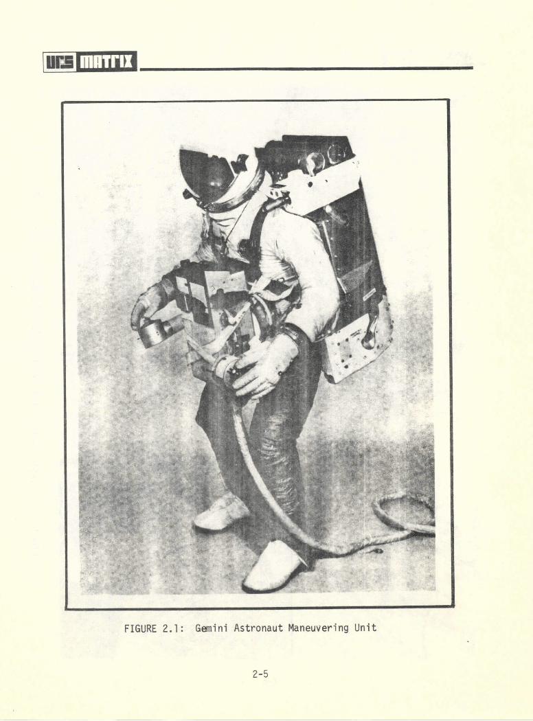
Astronaut Maneuvering Unit (AMU)
The Astronaut Maneuvering Unit (AMU) flown on the Gemini Program (Figure
2.1) was a backpack system consisting of a basic structure and six major sub-
systems: propulsion, flight control, oxygen supply, power supply, system
status and communications. The unit was designed to allow the EVA crewman to
maneuver in space completely independent of spacecraft systems. The AMU was
flown on Gemini IX under Air Force experiment DO12; however, the unit was not
evaluated on-orbit due to inadequate crewman restraints. (The planned AMU test
on Gemini XII was cancelled to allow more time to be devoted to restraint design
evaluation.) The AMU contained an integrated crewman oxygen supply subsystem
which supplemented the EVA life support system and provided for approximately
one hour of operation. The total unit weighed 76.3 kg. (168 lbs.) and contained
approximately 10.9 kg. (24 lbs.) of hydrogen peroxide propellant.
Automatically Stabilized Maneuvering Unit (ASMU)
The ASMU (Figure 2.2) was a back-mounted unit designed to evaluate direct,
rate gyro, and control moment gyro (CMG) control modes for maneuvering equipment
on Skylab experiment M509. The major components of the system were: structural,
propellant, attitude control, electrical, telemetry, and control and displays.
The maneuvering unit dimensions were 1.2 x 1.1 x .69 m. (48.0 x 41.5 x 27.0 in.)
in the deployed configuration, and the unit weighed 116.3 kg. (256.5 lbs.). Each
rechargeable propellant subsystem provided approximately 5.0 kg. (11 lbs.) of
2-4
liii! iiii i
HIN.
FIGURE 2.1: Gemini Astronaut Maneuvering Unit
2-5

F
FIGURE 2.2: Skylab Automatically Stabilized Maneuvering Unit (ASMvU)

GN2 for 30 minutes operational time. The ASMU and a handheld maneuvering unit
were evaluated on the Skylab Program inside the Orbital Workshop (OWS).
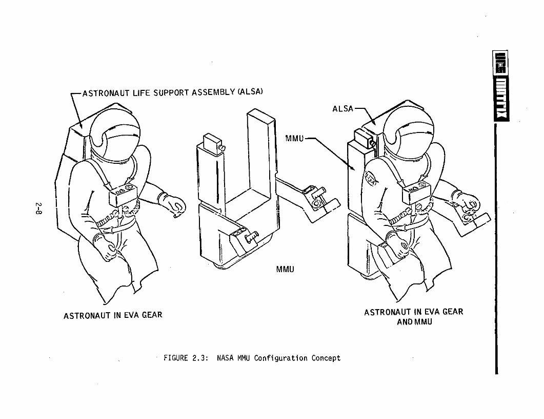
Space Shuttle Maneuvering Unit Concepts
Several preliminary artist concepts of Space Shuttle Manned Maneuvering
Unit external configurations have been prepared by NASA. Figure 2.3 depicts a
concept which would interface with existing portable life support systems and
the Skylab A-7L-B spacesuit. Since the exact configuration of the spacesuits
and life support systems for the Shuttle Program are undefined, the MMU con-
figuration may remain relatively fluid until these interfaces are better defined.
The concepts make no attempt to provide structural or operational features of
the proposed MMU. Figure 2.4 pictorially describes a hot gas unit for use in
conjunction with the concept shown in Figure 2.3.
The preliminary concept shown in Figure 2.5 depicts an MMU configuration
to interface with an integrated extravehicular mobility unit (EMU) concept.
The integrated EMU concept is in the study phase only as are the Manned Maneu-
vering Units.
2.2.2 Crew/MMU Reach and Visibility Analysis
A "paper" analysis was conducted to determine the crewman reach and
visibility envelope based on the MMU configuration shown in Figure 2.6. A
static mockup was fabricated, using estimated life support systems and space-
suit dimensional data (Shuttle concepts), to conduct the preliminary shirtsleeve
reach and visibility study (see Figures 2.7 - 2.9). The shirtsleeve analysis
was conducted using subjects with considerable spacesuit experience. The
results of the analysis isi shown in Figures 2.10 - 2.15.
The shaded area in Figure 2.16 shows the areas available for installing
ancillary equipment to the MMU. The areas can be reached by the crewman for
performing manipulative operations to secure, adjust or release operational
devices. The crewman's reach to the MMU structural member appears limited;
2-7
ASTRONAUT LIFE SUPPORT ASSEMBLY (ALSA)
ALSA
MMU
MMU
ASTRONAUT IN EVA GEAR ASTRONAUT IN EVA GEARAND MMU
FIGURE 2.3: NASA MMU Configuration Concept

ALSA
HOT GASMODULE
C -UNIT
HOT GAS MODULE
ASTRONAUT IN EVA GEAR, MMU,& HOT GAS MODULE
FIGURE 2.4: Hot Gas Module for MMU Concept

00
THRUSTERS
THRUSTERS ALSA
ALSA CONTROLSANDDISPLAYS
-- oTHRUSTERS
0 MMU CONTROLSAND DISPLAYS
MMU PROPELLANT TANK
FIGURE 2.5: MMU With Integrated EMU (Preliminary Concepts)
2-10

THRUSTERS
BASIC STI UCTURAL
CNFOI RATIO NIl ALSA LOCATION
CONTROL ARMS
PROPELLANT TANK NOT SHOWN o
FIGURE 2.6: Basic MMU Configuration for Study Analysis

FIGURE 2.7: MMU Soft Mockup--Used for Reach and Visibility Studies

urT i _ _ _ _ _ _ _ _ _ _ _
FIGURE 2.8: MMU Soft Mockup--Front Views
2-13

I-
FAde
FIGURE 2.9: MMU SoftMockup--Side Views

l__li_ ili__
Reach Envelope of Crewman in an MMU
Top View
2" 6.5 "
37"
Front View.. Side View 8"
The above sketch illustrates the reach envelope determined from pre-
liminary shirtsleeve studies using spacesuit-experienced subjects and
representative mockups. With limited MMU configuration information, it
was not possible to determine exact quantitative reach envelope data.
However, the "relative" reach information was considered sufficient to
determine general locations for attaching controls, ancillary equipment
and MMU stowage/restraint devices. The envelope shown represents the
maximum reach to perform useful hand operations.
FIGURE 2.101 Crewman-MMU Preliminary Reach Envelope
2-15

Tactile Reach Shaded
Top View
2618.5"-
20" 1" . ,
37"
Front View Side View
The shaded areas on the sketch depict the "blind spots" within the
crewman's reach envelope using the quasi MMU mockup. The mechanisms
located within these areas should be designed to be operated using
tactile cues or indirect (mirror) visual aids only. The unitized
mounting arrangement between the MMU structure and the crewman pro-
vides no relative motion for improving access. The envelope shown
represents the maximum reach required to perform useful functions
using the tactile sense only.
FIGURE 2.11: Crewman-MMU Tactile Reach Envelope
2-16

Top View
37"
/ 8"
Front View Side View
The shaded areas in the sketch above depict locations recommended
for mounting support hardware requiring a direct (eye-to-hardware)
visual interface (e.g., cameras, navigation equipment). The support
hardware should either be located within the shaded areas or designed
to be manipulated into the areas as required. Visual envelope recom-
mendations for control and display locations are shown in the subsequent
sketch.
FIGURE 2.12: Crewman-MMU Direct Visual Equipment Recommended Locations
2-17
Top View
12" 6.5"
S37"
. I
Front View Side View
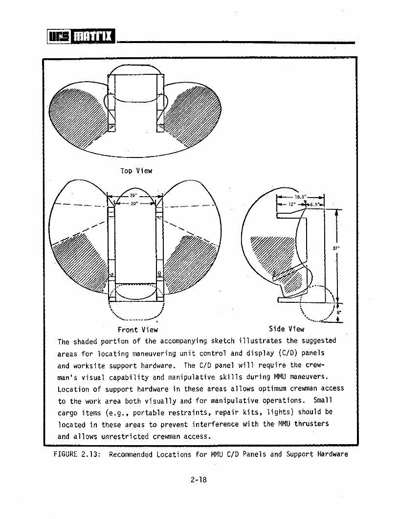
The shaded portion of the accompanying sketch illustrates the suggested
areas for locating maneuvering unit control and display (C/D) panels
and worksite support hardware. The C/D panel will require the crew-
man's visual capability and manipulative skills during MMU maneuvers.
Location of support hardware in these areas allows optimum crewman access
to the work area both visually and for manipulative operations. Small
cargo items (e.g., portable restraints, repair kits, lights) should be
located in these areas to prevent interference with the MMU thrusters
and allows unrestricted crewman access.
FIGURE 2.13: Recommended Locations for MMU C/D Panels and Support Hardware
2-18

Top View
20"1
I-01
Front View Side View
Cargo items such as small free-flying subsatellites, personnel
rescue systems and payload replacement modules may be transported
by the MMU. Attachment devices for transporting this category of
equipment should be. located forward of the crewman to position the
cargo near the center of gravity and below the crewman's forward
line-of-sight. This location will allow two-handed operations by
the crewman. Positioning or stabilizing large payloads when the
line-of-sight is blocked may best be accomplished by MMU and crew-
man facing the payload and "backing" the payload by use of mirrors.
(Additional study is required in this area.)
FIGURE 2.14: Recommended Location for MMU Cargo Attachment
2-19
Top View
- 20.. . o_12 ,8 6.5 ,
37"
S/ .8"
Front View Side View
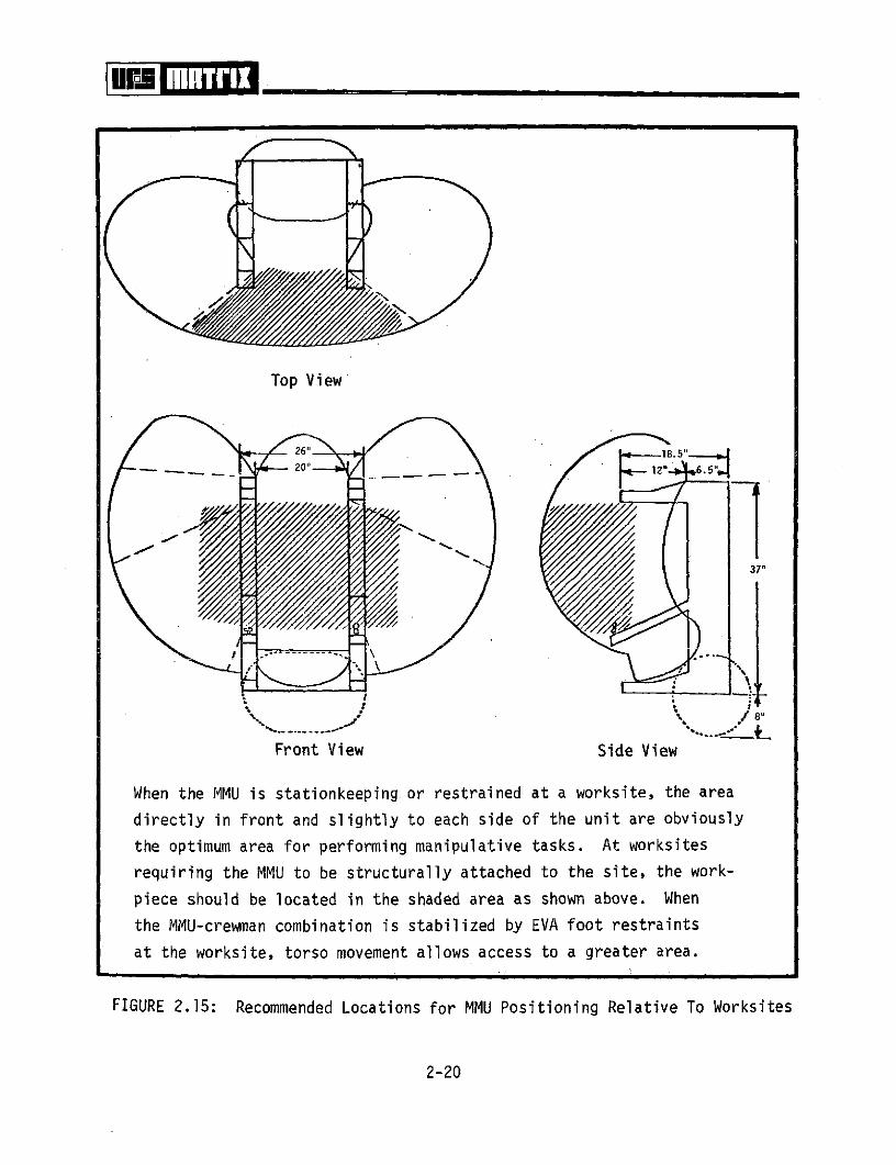
When the MMU is stationkeeping or restrained at a worksite, the area
directly in front and slightly to each side of the unit are obviously
the optimum area for performing manipulative tasks. At worksites
requiring the MMU to be structurally attached to the site, the work-
piece should be located in the shaded area as shown above. When
the MMU-crewman combination is stabilized by EVA foot restraints
at the worksite, torso movement allows access to a greater area.
FIGURE 2.15: Recommended Locations for MMU Positioning Relative To Worksites
2-20

THRUSTERS
ALSA LOCATION
ARM FOR CONTROLS
FIGURE 2.16: Crewman Reach and Visibility--Basic MMU Configuration

however, equipment may protrude into areas adjacent to the control arms. The
adjacent areas can easily be reached by the crewman.
Visibility of the MMU structural areas that can be reached is limited.
The areas below the control arm mounting points and the areas on the forward
ends are completely out of view. Areas on the outside surfaces of the con-
trol arms and upper thruster housings are also out of view. Devices located
in these areas will require designs based on identification by tactile sense
only or provide indirect viewing.
2.2.3 Study Developed Concepts
Two basic MMU configuration concepts were considered in the study--
unitary and modular. MMU configuration design was not a part of this study;
however, to develop concepts for securing a unit in the payload bay and attach-
ing ancillary equipment, the concepts shown in the following figures were used.
Unitary Designs
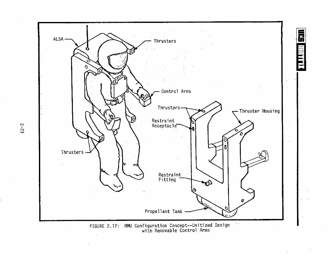
The concept shown in Figure 2.17 depicts a single structural unit with
the exception of removable control arms for compact stowage. The concept
incorporates external configuration features shown in the NASA artist sketches
(see Figures 2.4 and 2.5). A control arm adjustment and removal technique is
shown in Figure 2.18. The control arm telescopes to allow for crewman arm
length variations, pivots about the attach point for lower arm positioning, and
also pivots at the hand-controller interface for optimum control orientation.
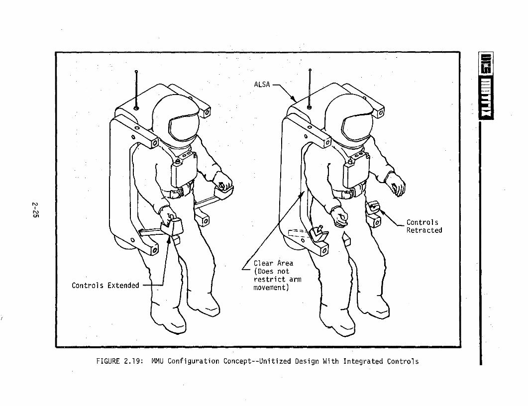
The concept provided in Figure 2.19 features modular MMU controls integrated
into the lower thruster housings. The control modules would be removable and
designed with a "downward-swept" arm-hand access configuration. The downward-
swept configuration would be limited to avoid crewman control logic disturbance.
The configuration in Figure 2.19 would allow greater side access to MMU support
equipment and front access to cargo and worksites.
2-22
ALSA Thrusters
Control Arms
ThrustersThruster Housing
RestraintReceptacle
0o
Thrusters
RestraintFitting
Propellant Tank
FIGURE 2.17: MMU Configuration Concept--Unitized Designwith Removable Control Arms

Arm Removal Release
MMU LowerStructure
Arm Adjustments
o o
Joint Adjustment Release
Arm Electrical Interface
FIGURE 2.18: MMU Control Arm Adjustment Concept
ALSA
\\0
0 Controls== Retracted
Clear Area(Does notrestrict arm
Controls Extended - . movement)
FIGURE 2.19: MMU Configuration Concept--Unitized Design With Integrated Controls
The units are secured to the crewman by a flexible strap system and
supplementary restraints as shown in Figures 2.20 and 2.21 (assumes non-
integrated EMU concepts). The concept shown in Figure 2.20 assists in restrain-
ing the crewman through inflatable contoured shoulder pads and a contoured seat
arrangement. The seat provides major adjustments for different percentile crew-
men by positioning the device prior to donning the MMU. The inflatable pads
are activated by the crewman to the required force. The flexible strap system
(perhaps a single strap) is attached to the MMU (see Figure 2.20) and the
portable life support system connected to the MMU with mechanical fasteners
(crewman releasable).
Figure 2.21 shows a passive supplementary crew restraint system. The
passive elements in Figure 2.21 are shown as pneumatic or fluid filled units
located at the shoulders. The contoured seat is adjusted by the crewman through
a mechanical system to the desired tension. The flexible strap system as in
the previous concept would be used.
The inflatable or passive bag units in the above concepts may be replaced
with retractable/adjustable rigid units (concept not shown) or the MMU thruster
structure in the shoulder area contoured and padded to interface with the space-
suit. If an integrated EMU system is developed, the candidate MMU-to-crewman
attachment may be a rigid mechanical system between the PLSS and the MMU.
Modular Design
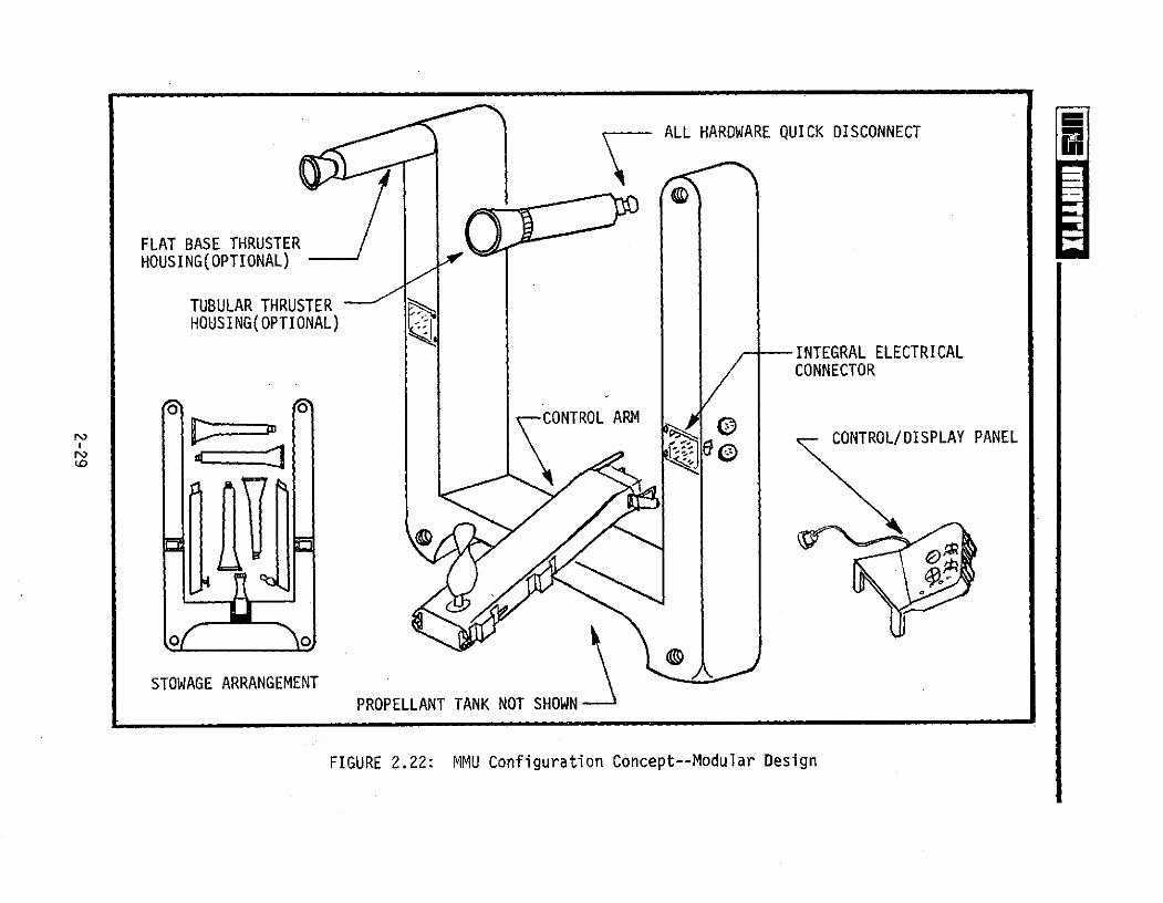
An MMU conceptual modular design is shown in Figure 2.22. The unit features
quick disconnects with backup locking characteristics on all removable components.
The contoured seat folds for stowage. The control and display (C/D) panel is
located on the left control arm and is removable. All units except the C/D
panel and the propellant tank may stow in the life support system space during
launch as shown in the Figure 2.22 inset. The forward thruster structures may
be configured as a relatively simple insulated tube or designed to provide
supplementary crew restraint as shown in earlier restraint concepts (Figures
2.20 and 2.21).
2-26

HEII I I___k_(_
Pneumatic Pressure ALSA(Pressurized ByCrewman From
Pressurized "Bags"
MMU
Separate Chambersfor Redundancy
MMU
Restraining Strap
Contoured Seat
Major Adjustments Only
(Prior To Donning)
FIGURE 2.20: MMU Supplementary Crew Restraint--Concept 1
2-27

Static "Bags"
Fluid Filled
Cushion
Restraining Strap
Contoured Seat Mount
Adjustment Lever - Actuation Position
(Stows Vertically During Maneuvers)
FIGURE 2.21: MMU Supplementary Crew Restraint--Concept 2
2-28
ALL HARDWARE QUICK DISCONNECT
FLAT BASE THRUSTERHOUSING(OPTIONAL)
TUBULAR THRUSTERHOUSING(OPTIONAL) .
INTEGRAL ELECTRICALCONNECTOR
o CONTROL ARMCONTROL/DISPLAY PANEL
o o
STOWAGE ARRANGEMENT S WNPROPELLANT TANK NOT SHOWN
FIGURE 2.22: MMU Configuration Concept--Modular Design

3.0 MMU ANCILLARY SUBSYSTEM CONCEPTS
Section 3.0 contains the MMU ancillary subsystem concepts developed as part
of the Manned Maneuvering Unit Mission Definition Study. The attachment and
stabilization of the MMU-crewman combination to various orbital systems will be
the major factor in efficiently performing EVA tasks. Subsection 3.1 presents
concepts for attaching and securing the MMU and the MMU-crewman combination to
the vehicle and payload structural configurations. The interfaces addressed
include the MMU to the Shuttle payload bay (launch, service, reentry); to pre-
pared and unprepared worksites on the Orbiter and free-flying satellites; to
the proposed personnel rescue system (PRS); to crewmen in EMU (Extravehicular
Mobility Unit) gear; and to another MMU .for on-orbit rescue support.
To provide a versatile MMU-EVA support system for the Shuttle Program,
several items of ancillary support equipment attached directly to the MMU will
be required. Supporting subsystems, such as module stowage provisions, light-
ing, cameras, tools, cargo, etc. will require attachments to the MMU to secure
the hardware during translation and worksite operations. Subsection 3.2 pre-
sents modular, add-on ancillary equipment concepts for interfacing support
hardware to the MMU.
3.1 ORBITAL SYSTEMS INTERFACES
Orbital systems that will require an interface with the MMU for performing
candidate Shuttle support tasks were identified in the MMU applications analysis
phase of this study. The interfaces are graphically illustrated in Figure 1.2
and reproduced on the following page. The chart categorizes the orbital systems
into four basic interface areas: Shuttle Orbiter, payloads, rescue systems and
another MMU. Since the MMU must be secured for transporting to and from orbit,
attachment concepts for use during launch, servicing on-orbit and reentry are
presented first--Section 3.1.1. Both fixed and portable MMU restraint concepts
are presented.
3-1

ORBITAL SYSTEMS - MMU INTERFACES
FREE-FLYING OTHERORBITER :RESCUEPAYLOADS MMUS
Rersonnel Suited Un- MannedCrewman mannedUnpre- Prepared Systems
pared Worksite
Launch/ Doff/Don, Worksite
Reentry Checkout/Service
The methods/techniques for temporarily attaching an MMU to the Orbiter or
a free-flying payload for on-orbit servicing operations will be similar and
require essentially identical types of attachment devices. The attachment
equipment will vary, however, between prepared and unprepared worksites. Pre-
pared worksites are configured prior to launch with interface provisions for
accepting EVA support equipment, such as foot restraints, portable workstations,
lights,module stowage, etc. Unprepared worksites have no structurally integral
provisions for accepting EVA support equipment. The EVA equipment must be
attached to the worksite basic structure when EVA is required. Subsection
3.1.2 is a compilation of the major concepts developed for interfacing an
MMU-crewman to a worksite, including both prepared and unprepared worksites.
Subsection 3.1.3 presents the concepts developed for interfacing an MMU
to personnel in a rescue configuration (e.g., PRS, spacesuit) and an MMU to
another MMU for supporting rescue operations.
3.1.1 MMU Restraint Systems
This subsection provides concepts for restraining the MMU for launch,
servicing, reentry and on-orbit donning/doffing activities. The concepts
depict attachment fixtures that may either be fabricated integral to the
Orbiter and payloads or designed as a "bolt-on" unit. The bolt-on MMU attach-
ment fixture would be attached at a specified location prior to launch.
3-2

The first concept (Figure 3.1) satisfies MMU launch/reentry restraint
requirements by using overcenter latching mechanisms, attached to each side of
the MMU, and three fixed pins. The overcenter locking and alignment guides
device serve to initially restrain the MMU to allow final alignment of the
three primary load bearing pins. After alignment, the overcenter lock secures
the MMU to the launch/reentry interface. A lock-lock device is incorporated
into the overcenter locking system to ensure positive latching. Actuation of
the overcenter latching mechanism is a pulling motion which aids in stabilizing
the crewman during on-orbit MMU restowage. Pushing the overcenter latching
device releases the locking mechanism and aids in departing the MMU stowage
area when the unit is donned. Flexible guides assist the crewman in aligning
the unit for doffing, and handrails provide the necessary aids for ingress/
egress of the foot restraints. Both the handrails and foot restraints fold
when not in use.
Figure 3.2 presents a concept similar to the overcenter latching arrange-
ment for restraining the MMU during launch, servicing, reentry and don/doff
activities. The concept utilizes a ball and socket system and two fixed pins.
The ball unit and the fixed pins are load bearing members. The ball interface
and the alignment guides temporarily restrain the MMU on initial contact. The
MMU is firmly secured to the stowage location by actuating a latching handle.
The active latching mechanisms depicted in Figures 3.1 and 3.2 are located on
the MMU mounting interface. The MMU contains only the passive portion of the
connecting mechanisms. Similar alignment and restraint ingress/egress provisions
are included'for the ball and socket attachment concept as shown in the pre-
vious illustration.
Figure 3.3 provides a concept in which the active latching mechanisms are
integrated into the MMU structure. The passive side of the connectors are
attached to the MMU stowage interface and the crewman's portable life support
system.
The latching arrangement is designed to accommodate MMU stowage and also
attachment to the crewman via the EMU system. The attachment mechanisms may
3-3

Flexible Guides (2)Ml
Restraint Pins (3)
MMU
Folding Guiderails
Positioning Guide
(top view) MMUThruster
Orbiter Bulkhead \--Overcenter Locking -- Folding Foot Restraintsor Stowage Interface Device (each side)
FIGURE 3.1: MMU-to-Orbiter Interface--Launch, Reentry and Servicing Restraint(Overcenter Side Locks and Pins)

Flexible Guides T
F. G Restraint Pins (2) g
Ball Receptacl
Ball Restraint
Folding Guiderails -
jPropellant Tank
Positioning Guide Orbiter Bulkhead MMU
Foot Restraint
Lock
Overcenter Lock Open
FIGURE 3.2: MMU-to-Orbiter Interface--Launch, Reentry and Servicing Restraint(Ball and Socket Plus Pins)

Alignment Guides
Thrusters
Right-Hand pPush-ButtonReleases Aft Locks
Left-HandPush-ButtonReleases Forward LatchLocks (Typical
4 Places)
Control Arms
(Propellant Tank Not Shown)
FIGURE 3.3: MMU-to-ALSA and Orbiter Restraint Attachment Concept(Slider-Type Interfaces)
3-6

be slider-type devices with a mechanical push-button or lever-linkage release
system actuated by the crewman while in the unit. Solenoid actuated latching
mechanisms with mechanical backup were also considered. The final alignment
guides are integral to the MMU with gross alignment provided by handrails and
foot restraints as shown in Figure 3.4. The handrails provide guides for the
crewman when donning the MMU (crewman in EMU configuration) or restowing the
MMU after an EVA mission. To don the MMU the crewman would back into the
stowage station using the ingress aids (handrails) and ingress the foot re-
straints. Mirrors would be provided to aid final alignment for both MMU-to-
crewman attachment and MMU stowing.
Depending on the final external configuration of the Space Shuttle MMU,
numerous alignment aids of varying configuration can be provided to assist in
donning and stowing the MMU on-orbit. The concepts shown in Figures 3.1 and
3.2 indicate flexible (semi-rigid) guides for alignment of the upper portion
of the MMU and a ramp to contact the propellant tank for "tactile" assistance.
All MMU ingress and stowage aids shown in the concepts fold or retract when not
in use.
The numerous payload/experiment arrangements in the Orbiter payload may
necessitate affixing the MMU at various locations on the Orbiter or payloads.
Figure 3.5 depicts a bolt-on MMU interface fixture concept. The fixture may
be attached at any desired location that provides sufficient structural support
for MMU launch and reentry.
The preceding concepts have combined MMU restraint systems for launch and
reentry with those used in servicing and donning the units while in orbit. It
may be desirable to provide separate systems for these functions. The temporary
on-orbit restraints shown in Figures 3.6 and 3.7 would be used to secure the
MMU during servicing and initial checkout operations. Such temporary restraint
devices may also be used in conjunction with MMU launch/reentry restraints. The
primary launch/reentry restraint system may best be designed such that the
release mechanisms are operated prior to donning the MMU. The temporary MMU
restraints would then be used during MMU donning and doffing operations. The
3-7

Retention Points (4)
Rails Act As Guides
Folding Ingress Rails
Foot RestraintsFold For Stowage
FIGURE 3.4: MIMU Donning Station Concept (Fixed)

Portable MMU Restraint(Lightweight Built-UpSections, e.g., Honeycomb)
Alignment Guides
Bolt To Pallet, PayloadOr Bulkhead
MMU
Latching -
Restraints
Restraint Pins
MMU Controls
Note: MMU restraint designed to attach to
various Shuttle Orbital elements
FIGURE 3.5: Removable Launch/Reentry MMU Attachment Concept
3-9

Retaining Guides(4 Places)
Bungees (oneeach side)
FIGURE 3.6: Bungee Restraint for MMU Donning/Checkout Concept
Retaining Guides4 Places
Spring provides
tension to holdunit in placeduring donning
pip-pin
FIGURE 3.7: Tension Bar Restraint for MMU Donning/Checkout Concept
3-10

relatively simple temporary MMU restraint concepts (Figures 3.6 and 3.7) assure
the crewman the capability to release himself from the donning station. Depend-
ing on the final MMU configuration, access to the aft areas of the unit for on-
orbit servicing may be required. Figure 3.8 describes a "swing-out" fixture
that may be designed to provide the following:
* Access to all areas of the MMU for on-orbit servicing
* Access (direct reach and visibility while in the unit) to the latching
mechanisms for retrieving and stowing the unit on-orbit
* Launch and reentry restraint when positioned and secured to the Orbiter
payload bay or payload structure
For launch/reentry the MMU servicing support fixture (Figure 3.8) would
secure the MMU with mechanical fasteners similar to previously shown concepts.
For servicing, the mechanical fasteners would be released, allowing the unit
to swing away or extend from the mounting surface. The MMU may be released or
restowed while in the extended configuration by one crewman with adequate
visibility and reach, and without the need for extensive guides and visual aids
(e.g., mirrors, tactile aids).
On-orbit contingency situations are feasible in which an MMU would be
required for servicing operations outside the Shuttle Orbiter when the payload
bay doors cannot be opened. Since the current stowage location is outside the
Orbiter cabin, the MMU would be transferred from the payload bay, through the
cabin, and out the Orbiter side hatch. The side hatch may not accommodate
the MMU-crewman combination (MMU configuration dependent). Under this con-
dition, the MMU would be donned from a special fixture deployed from the cabin
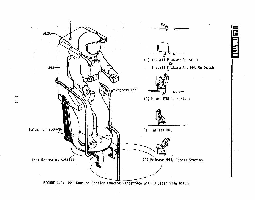
through the side hatch. The concept shown in Figure 3.9 depicts a fixture that
would be attached to the side hatch prior to crewman egress. Depending on the
MMU size and configuration, the MMU and fixture may be deployed through the
hatch as a unit. The EVA crewman would egress the cabin using mobility aids
provided on the fixture and ingress the foot restraints and MMU. The foot
restraints pivot to allow the crewman to rotate into the proper orientation
for MMU donning and doffing. The reverse procedure would be employed for
3-11

Hinged Door Overcenter Locking Arrangement
(Basic Concept)
MMU
Alignment Guides (2)
-Overcenter LatchingDevice (2)
Latching Restraint Pins And 0
MMU Guides (2)
Bolt-On Fixture Restraint Pins
Folding Ingress Aid
Note: MMU can be doffed by one crewmanin the "open" position and "closed"for stowage
FIGURE 3.8: MMU "Swing-Out" Servicing Attachment Concept
ALSA-
(1) Install Fixture On HatchOr
MMU - Install Fixture And MMU On Hatch
Ingress Rail
(2) Mount MMU To Fixture
Folds For Stowage (3) Ingress MMU
Foot Restraint Rotates (4) Release MMU, Egress Station
FIGURE 3.9: MMU Donning Station Concept--Interface with Orbiter Side Hatch
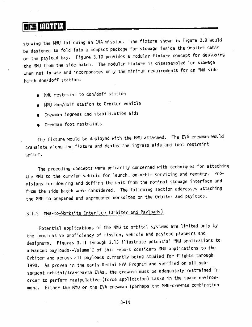
stowing the MMU following an EVA mission. The fixture shown in Figure 3.9 would
be designed to fold into a compact package for stowage inside the Orbiter cabin
or the payload bay. Figure 3.10 provides a modular fixture concept for deploying
the MMU from the side hatch. The modular fixture is disassembled for stowage
when not in use and incorporates only the minimum requirements for an MMU side
hatch don/doff station:
* MMU restraint to don/doff station
e MMU don/doff station to Orbiter vehicle
e Crewman ingress and stabilization aids
* Crewman foot restraints
The fixture would be deployed with the MMU attached. The EVA crewman would
translate along the fixture and deploy the ingress aids and foot restraint
system.
The preceding concepts were primarily concerned with techniques for attaching
the MMU to the carrier vehicle for launch, on-orbit servicing and reentry. Pro-
visions for donning and doffing the unit from the nominal stowage interface and
from the side hatch were considered. The following section addresses attaching
the MMU to prepared and unprepared worksites on the Orbiter and payloads.
3.1.2 MMU-to-Worksite Interface (Orbiter and Payloads)
Potential applications of the MMU to orbital systems are limited only by
the imaginative proficiency of mission, vehicle and payload planners and
designers. Figures 3.11 through 3.13 illustrate potential MMU applications to
advanced payloads--Volume I of this report considers MMU applications to the
Orbiter and across all payloads currently being studied for flights through
1990. As proven in the early Gemini EVA Program and verified on all sub-
sequent orbital/transearth EVAs, the crewman must be adequately restrained in
order to perform manipulative (force application) tasks in the space environ-
ment. Either the MMU or the EVA crewman (perhaps the MMU-crewman combination
3-14

MMU retention points (4)-
* Can be bolted to pallets
* Can be mounted to hatch seal areas
Ingress aids
Disassembles for stowage
Foot restraints
MMU-to-vehicle interface
FIGURE 3.10: Modular MMU Donning Station Concept

FIGURE 3.11: MMU Application to Large Geodetic Space Structure Assembly
3-16

MMU Crewman
Solar Array
RMS
FIGURE 3.12: MMU Application to Automated Payload--Repair at Prepared Worksite

~E7i~91
;Ooo
~i~j~r~i~i~l~iiii".:~;l~:~:~ji:':~iiiiiiiiih ii
9
~i~i~i~le
:'i~~~l~i~j:::~::ii:~-j~ii~i:;ijiiliiii.
::~ iLY,:;:- :::::~i..:;:,,,:, :--.. ;~~ijii~j~i~i
~ ( c
iLi~' i~"'''
\it- a
-:ii:iiiiic_~il:r:i~;~':;; :';si ~~i~ i;~iiiiI:; "i
~:""'~~i~i ii~i-i~Pi I~sisia~iiii~i~jijj.i ~i~'"~~ii~':' :li~:illj~ i~~s ~riiii ii s~~ ~v~i:::::::: ~ ::;:' I ~ a~ .:(: ~il~B1~~:::'~:~:,, - :r:~ii-~i~ :'' ~i:iiiiiiiii
;; : .:: ~i~ii~_,i: i~jii@i9ii~ rip:; "':'::":" : :::'; i~-:':~~:i "( ~!i:i'ii~j~ ; ii~%i~ib.$ "9""r:,,:-:,~-:iiiiil-.,~ ~Li~i:~i~~ i:ir!a::-i :~iiii1-:::: ::.:,; -::~:::::::::.:--;,:::..:--::~:~::;:--:::-~i~~l;~:':.r:
s:~:I~iii:i:-.:- iiiii~
im, -:ic~i
~ ~iiiiiiLr:~
~ ~iU:iii
i 1-
i~i~ii~ r~iiiii~i.~ ~:jii~~VGjl~j B;:.'-'-ii li:iiii ,
FIGURE 3.13: ~U Application to Large Antenna System--Repair at Unprepared Worksite
3-18
for special application) must be restrained at the worksite. Restraining the
MMU-crewman system will involve attachment to either a prepared or unprepared
site on the Shuttle Orbiter and payloads.
Prepared worksites are defined as interfaces provided prior to vehicle
launch to support planned EVA functions. Such worksites contain adequate pro-
visions for attaching the required EVA support hardware. An unprepared worksite
contains no provisions for EVA functions, and the crewman must transport and
attach the required restraint equipment to the orbiting structural interface.
The restraint design criteria apply equally to the payloads and Shuttle Orbiter
for both prepared and unprepared worksites. Therefore, the MMU/EVA crewman-to-
worksite interface concepts presented in the following paragraph are applicable
to all orbital systems..
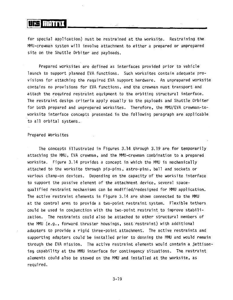
Prepared Worksites
The concepts illustrated in Figures 3.14 through 3.19 are for temporarily
attaching the MMU, EVA crewman, and the MMU-crewman combination to a prepared
worksite. Figure 3.14 provides a concept in which the MMU is mechanically
attached to the worksite through pip-pins, astro-pins, ball and sockets or
various clamp-on devices. Depending on the capacity of the worksite interface
to support the passive element of the attachment device, several space-
qualified restraint mechanisms can be modified/redesigned for MMU application.
The active restraint elements in Figure 3.14 are shown connected to the MMU
at the control arms to provide a two-point restraint system. Flexible tethers
could be used in conjunction with the two-point restraint to improve stabili-
zation. The restraints could also be attached to other structural members of
the MMU (e.g., forward thruster housings, seat restraint) with additional
adapters to provide a rigid three-point attachment. The active restraints and
supporting adapters could be installed prior to donning the MMU and would remain
through the EVA mission. The active restraint elements would contain a jettison-
ing capability at the MMU interface for contingency situations. The restraint
elements could also be stowed on the MMU and installed at the worksite, as
required.
3-19

Pip-Pin release
Sl ider-type interfaceto MMU
Nonrotationalpip-pin
Ball Release .
Restraint ReleaseUnder Arm
Ball And Socket Concept
FIGURE 3.14: Concept for MMU Attachment to Prepared Site

Detent Mechanism
PivotRelease
Mechanism \
NO .56 m.
(22 in.) (
FOOT PLATE
0o o
20.3 cm. FOOT RESTRAINT ADAPTER(8 in..64 m.
(.25 in.) 0
PIP PINS (3)(10 in.) 0
FIGURE 3.15: Tripod Foot Restraint Concept
3-21
INGRESS AND PORTABLE LIGHT WITH SELF-
STABILIZATION CONTAINED BATTERIES ORPAYLOAD BAY ELECTRICALOUTLET--SNAPS ONTO RAILAND IS TETHERED
TEMPORARY J oSTOWAGE HOOKS
ADJUSTABLE
TOOL KIT FASTENS TO RAILSPUSH-BUTTON USING VELCRO STRAPS, PIP,RELEASE- PINS, ETC.
MECHANISMS ,
FOOT PLATE ATTACHES TOWORKSTATION USING BOLTS,ASTROPINS, QUICK CONNECT/DISCONNECT FASTENERS, ETC.
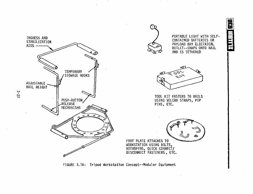
FIGURE 3.16: Tripod Workstation Concept--Modular Equipment
FOLDING SEQUENCE (RAILS STOWED CONFIGURATIONMAY ALSO BE REMOVED)
EQUIDISTANT HOLES ON MOUNTING SURFACE ALLOW 3 WORKSTATIONORIENTATIONS 1200 APART
@ REAR SUPPORT MEMBER ALLOWS WORKSTATION ADJUSTMENT IN PITCH
© CIRCULAR HOLE PATTERN ALLOWS DISCRETE YAW POSITIONING OFWORKSTATION
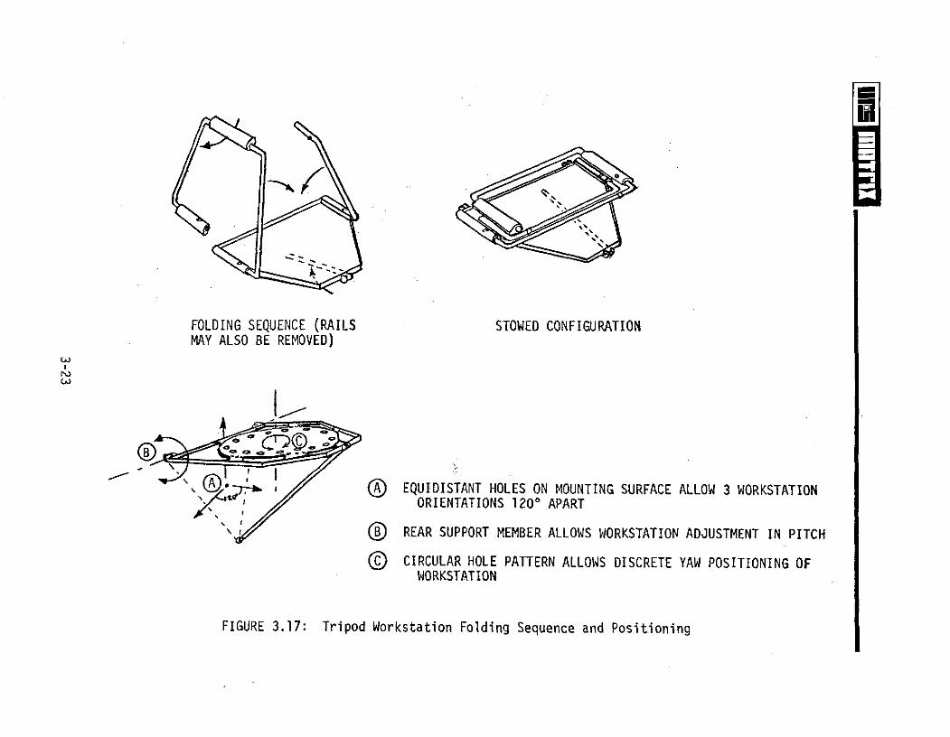
FIGURE 3.17: Tripod Workstation Folding Sequence and Positioning

Compression Spring
Bearing-
Pivot
Folding Handrail
Pitch 900±
" Pivot
2 , Holes Equidistant
Rotating Handle/Ball Release
FIGURE 3.18: Foot Restraint Attachment Concept--Prepared Worksite(Ball and Sockets)

Temporary
Deployment Release Stowage Hook
Stowage Hook Release
ToUmbilical Clip 134.0 Inches
16.25" L
HoneycombBase Plate
Pip-Pin (Rigid
Skylab Foot Mounting Only) -- ~
Stowed Configuration Restraints
Modular Add-On Items: is.
* Ingress Rails* Tool Kit 19.0"* Lights 2 \.0"* Camera Mount* Equipment Hooks
And Tethers Base Plate May Be ConfiguredTo Interface With A VarietyOf Adapter Brackets ForUniversal Mounting
FIGURE 3.19: Portable Workstation Concept--Modular Equipment
Figures 3.15 through 3.18 depict concepts for restraining the MMU crewman
to a prepared worksite. The portable workstation concept shown in Figures 3.15
through 3.17 would be mounted at the worksite using three holes in an equilateral-
triangular pattern. The workstation concept would provide adjustments in the
roll, pitch, and yaw axes and is a modular design to range from a simple foot
restraint unit to a completely equipped workstation. The workstation concept
is designed to accept only those modular elements required for a specific task(s)
and folds for transporting and compact stowage (Figure 3.17).
Figure 3.18 provides an alternate restraint concept for attaching to a
three-hole proposed interface. The attachment interface would be equipped with
alignment/retaining inserts for accepting a ball-type releasable probe. The
restraint provides a folding crewman ingress aid and may be easily transported
by the MMU to remote sites. Figure 3.19 depicts a previously developed concept
of a modular-portable workstation. The workstation may be secured to a pre-
pared worksite prior to launch by bolts, pip-pins, etc. or transported to the
worksite on-orbit. The workstation may also be attached to unprepared worksites
by utilizing attachment concepts developed in subsequent sections of this report.
Unprepared Worksites
Several typical attachment devices used on the Skylab Program to interface
with various structural members are illustrated in Figure 3.20. Similar inter-
faces and attachment techniques are applicable to the Space Shuttle for attach-
ing the MMU to unprepared worksites. However, unique attachment devices for
each candidate interface are undesirable for orbital application. Figure 3.21
provides a concept capable of interfacing with a variety of structural shapes.
The "C" clamp attachment device would incorporate adjustable and/or removable
inserts to provide the "universal" interface. Mounting interfaces would be
provided on the MMU structure and portable workstations to accept the "C"
clamp.
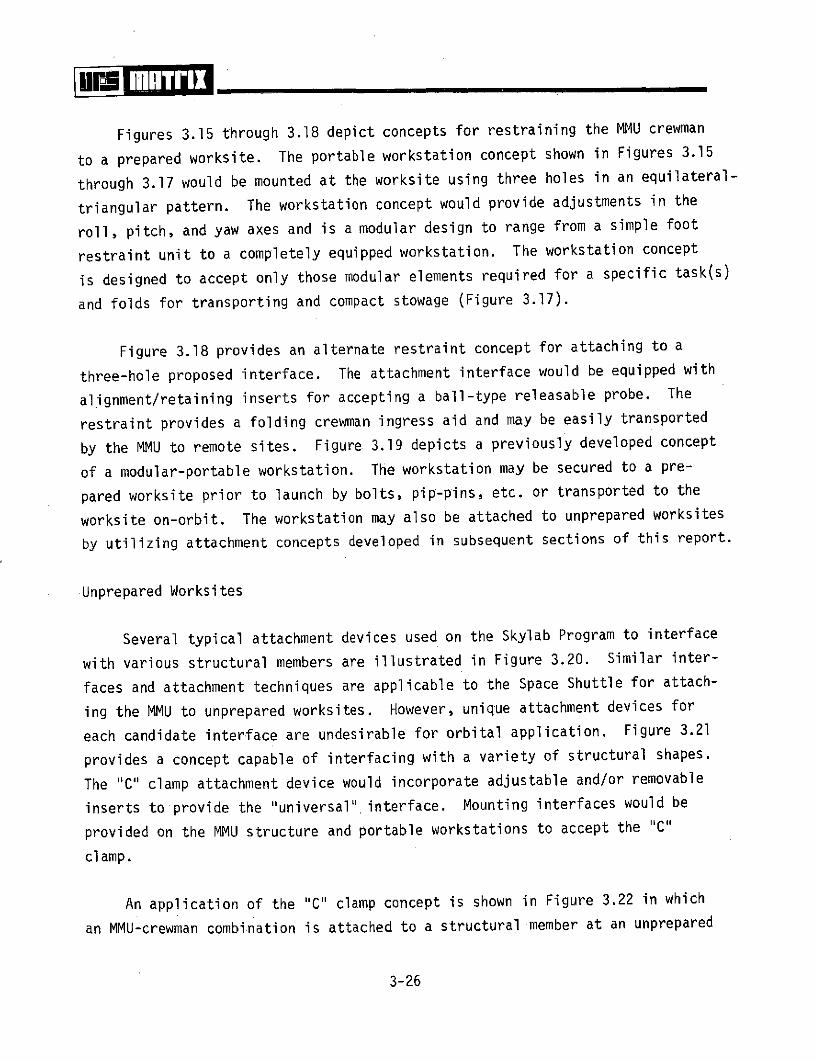
An application of the "C" clamp concept is shown in Figure 3.22 in which
an MMU-crewman combination is attached to a structural member at an unprepared
3-26

Skylab Universal Mounting FixtureTo Interface With Handrails
SO20 EVA Mount To InterfaceWith Tubular Strut
S149 Mount To Interface WithEdge Of Structure On ATM
FIGURE 3.20: Typical Attachment Brackets from Previous Space Programs
3-27

Tool Interface
AccommodatesVarious Diameters
SInterchangeable Jaws
Universal Clamp Concept
Representative Applications
FIGURE 3.21: Universal "C" Clamp Attachment Device Concept
3-28
ALSA
MMU Controls
MMU
Universal Clamp WithRemovable Inserts
Ball Joint
TYPICAL STRUCTURALINTERFACES
FIGURE 3.22: Universal Clamp Concept for MMU Restraint--Unprepared Worksite

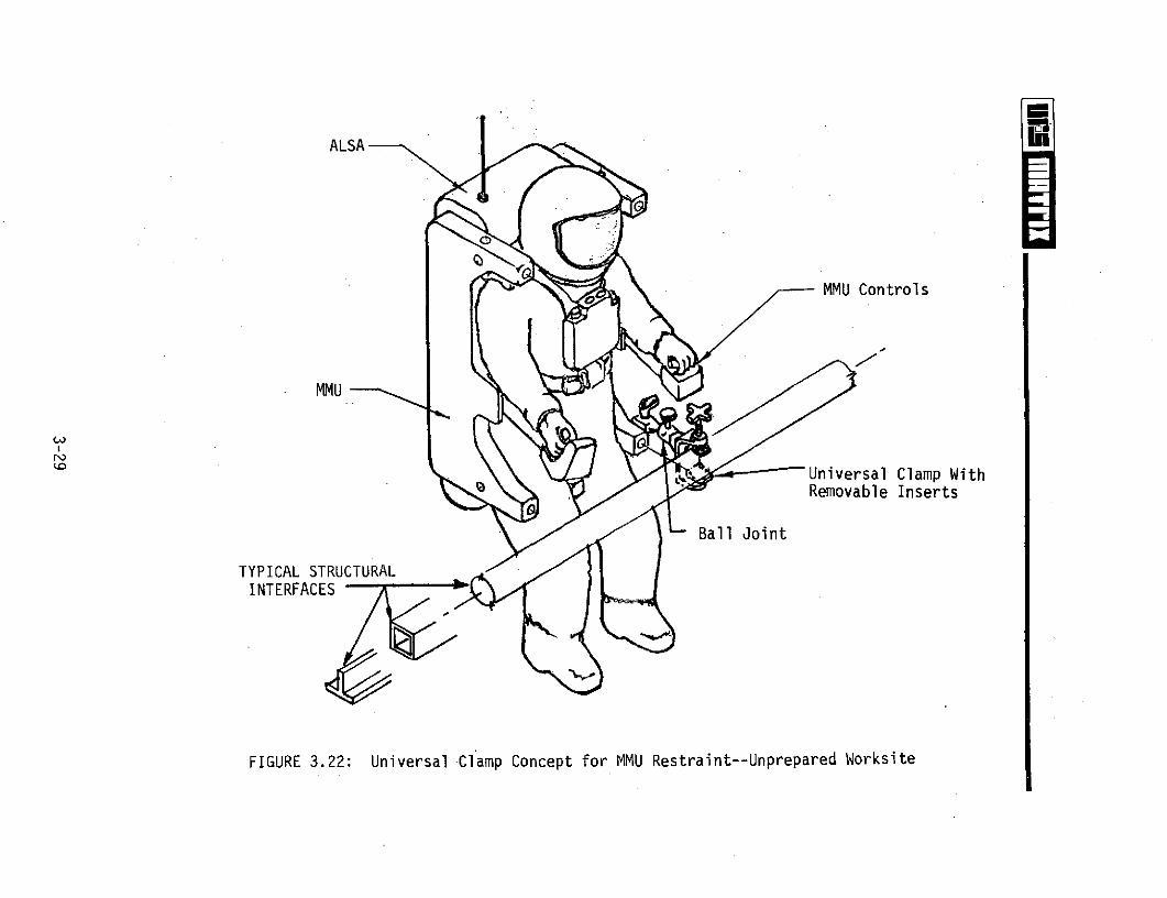
worksite. Figure 3.23 provides additional details for attaching the "C" clamp
concept to an MMU. Since the MMU contains various pneumatic components for
thruster operation, the pneumatic system may feasibly be utilized to actuate
MMU attachment devices. One such concept is shown in Figure 3.24. Figures 3.25
and 3.26 illustrate optional concepts that may be designed for either mechanical
or pneumatic operations at the MMU-to-worksite interface. Optional end effectors
would be provided for grasping structural configurations. The end effector
would be spring-loaded to automatically actuate on contact and include a manual
backup locking/release mechanism. The specific type of end effector would be
connected to the MMU prior to egressing the MMU stowage locations or be one of
a selection of end effectors stowed on the MMU. The MMU structural interface
would be mechanical with a push-button release mechanism integral to the MMU
structure. The end effector linkage is designed for contingency removal by
the crewman for releasing the MMU from an orbital interface. Figure 3.26
depicts a concept for remotely operating an adjustable restraint mechanism to
attach beyond the crewman's reach.
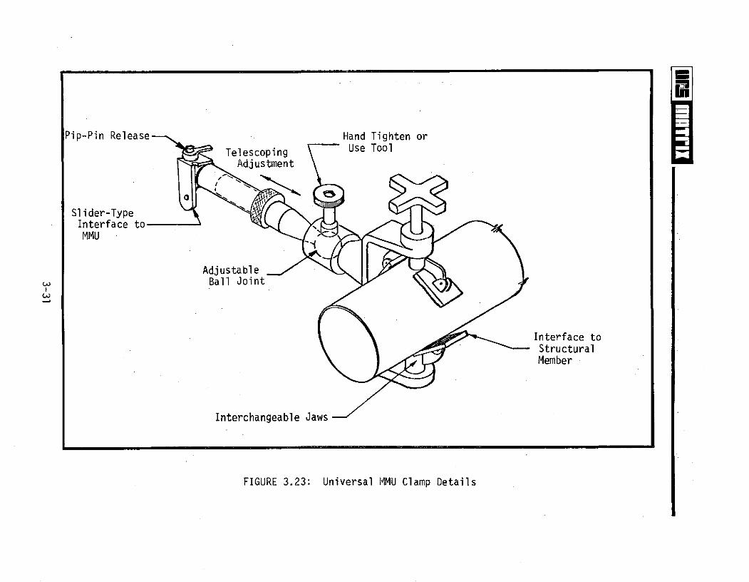
Figure 3.27 provides a concept for attaching the previous "C" clamp re-
straint device (Figure 3.21) to a portable foot restraint or modular workstation.
A concept for attaching a portable workstation to the edge of a flat plate, leg
of a structural angle, etc. for applying relatively large forces or torques is
shown in Figure 3.28. The short "spikes" (approximately .08 cm. (.030 in.))
would form detents in the structural member to prevent slippage. The unit would
be hand-tightened by the EVA crewman and secured by standard hand tools prior to
workstation ingress. Each of the concepts above (Figures 3.27 and 3.28) pro-
vides a capability to restrain the crewman at an unplanned worksite in lieu
of attaching the MMU. Restraining the crewman allows more latitude at the work-
site for task performance.
The concepts provided in the remainder of this subsection address attaching
MMU and crewman restraint systems to relatively flat, unprepared surfaces on the
Orbiter or payload exteriors. Repair of the Orbiter Thermal Protection System
(TPS) appears to be a strong MMU application; however, the TPS is restricted to
.6 kg/cm2 (8 Ib/in 2 ) surface loading. Adhesive restraint surfaces which
3-30
Pip-Pin Release Hand Tighten or
Telescoping Use Tool
Adjustment
Slider-TypeInterface toMMU
AdjustableBall Joint
Interface toStructuralMember
Interchangeable Jaws
FIGURE 3.23: Universal MMU Clamp Details

Switches:
e On - Off
SUp - Down
QD to MMU
Interchangeable Inserts ForStructural Interfaces
FIGURE 3.24: Pneumatic MMU Clamp Concept

Spring actuated clamp similarto Skylab umbilical clamps
Handrail adapter
FIGURE 3.25: Grapplers For Restraining MMU to an Unprepared Worksite
Latching Contr 1
FIGURE 3.26: Side-Mounted Device For Attaching MMU to Unprepared Worksite
3-33

Eiiii L 7
Portableorkstabletion Bolts To WorkstationWorkstation (Allows DiscreteYaw Positioning)
Tighten By Hand
Special Designed Ball And Or Tool
Socket Allows OrientationAdjustment
Clamps ToStructuralMembers
FIGURE 3.27: Universal Clamp-to-Portable Workstation Interface
3-34
Tool Interface On HandleKNURLED CLAMP "For Securing Workstation
ADJUSTABLE TO VARIOUS SPIKES APPROXIMATELY
MEMBER THICKNESSES .08 cm. (.030 in.)LONG WITH BLUNT POINT
Workstation AttachesTo Flat Plate
GUIDES
ANGLE OR PLATEON VEHICLE
SPIKES SLIGHTLY DEFORMSTRUCTURAL MEMBER
VEHICLE SURFACE
FIGURE 3.28: Workstation-to-Angle/Plate Attachment Concept

sufficiently distribute the loading to the Orbiter structure appear promising.
If applied to the Orbiter TPS, all equipment, including the adhesive, must be
removed prior to reentry. Adhesive systems with one of the following properties
may be applicable:
* Adhesive degrades and releases within a specific time after exposure
to the space environment
e Adhesive releases immediately upon application of release agent
- Release agent is compatible with EMU subsystems and TPS
e Encapsulated (miniature) adhesive release agent capable of being
released with a special "radio" frequency input
* Mechanical release of adhesive release agent located in restraint
system
* Heat applied/released adhesives utilizing auxiliary MMU power packs
* Mechanical release of adhesive restraints by segments (strength of
adhesive must be below .6 kg/cm 2 (8 lb/in 2 ) to avoid TPS damage)
The availability of adhesives possessing the desired characteristics were
not researched by the contractor. The reader is referred to major adhesive
manufacturers' specifications and the "Space Shuttle Program, Drawings, Specifi-
cations, and Associated Data," Systems Integration and Orbiter Vehicle Develop-
ment, JSC-07300, August 15, 1974, for detailed information.
Figure 3.29 provides a concept for attaching a set of crewman foot
restraints or a portable workstation to a flat surface using three adhesive
pads. The adhesive pads incorporate a socket-type interface for the expendable
ball attachment devices shown in Figure 3.18. The semi-rigid adhesive pads and
their triangular arrangement will compensate for slight surface discontinuity
and/or curved surfaces. If the restraint pads can remain on the surface after
the EVA mission, the'workstation only can be removed and returned to stowage.
If the restraint pads are adhered to the Orbiter TPS, both the adhesive pads/
fixtures and remaining adhesive must be removed (requires detailed study to
determine the amount of adhesive residue allowed to remain on each Orbiter TPS
3-36
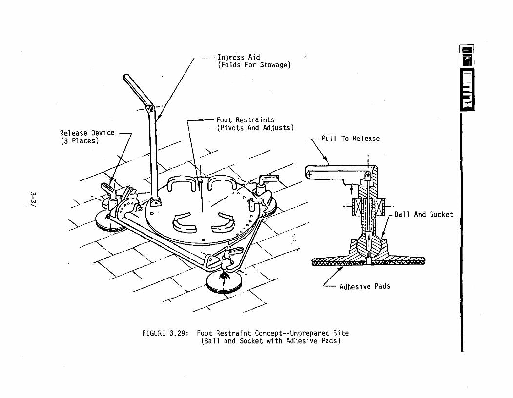
Ingress Aid(Folds For Stowage)
Foot RestraintsRelease Device- (Pivots And Adjusts)
(3 Places) Pull To Release
Ball And Socket
dhesive Pads
FIGURE 3.29: Foot Restraint Concept--Unprepared Site(Ball and Socket with Adhesive Pads)
surface). The size of the adhesive pads may vary depending on the force appli-
cation required at the specific worksite. Each 10 cm. (=4 in.) diameter2 2
adhesive pad with a bonding strength of .4 kg/cm2 (=6 lbs/in 2) will provide
approximately 35 kg. (75 lbs.) reactive force.
An adhesive restraint system requiring greater reactive force capability
than the previous concept is shown in Figure 3.30. The adhesive pad would attach
only to relatively smooth surfaces. The restraint fittings located on the
adhesive pad swivel to allow proper alignment with the workstation attachment
devices. The adhesive pad may be designed for segmented mechanical release or
release by adhesive solvents. An application of a portable workstation/
adhesive pad concept is depicted in Figure 3.31. The illustration shows an
MMU-clad EVA crewman performing a TPS repair on the Shuttle Orbiter.
Figure 3.32 presents a concept for attaching the MMU to a flat surface
using segmented adhesive pads. The pads would be sized depending on the force
required at the worksite to perform the desired EVA tasks. For removal, the
concept would permit only .small portions (strips) of the adhesive bond to be
concurrently broken until the complete unit is removed. The adhesive pad inter-
face to the MMU would utilize previously discussed concepts with a contingency
jettison capability. An adhesive pad mounted on each control arm, supple-
mented with flexible tethers, should provide sufficient restraint for most MMU
Shuttle applications.
An adjustable tether concept for crewman mobility and stabilization along
an extended worksite is shown in Figure 3.33. Tether attachment fittings could
be adhered to the Orbiter TPS or adjustable fixtures provided for attaching to
the Orbiter wing leading and trailing surfaces, vent openings, access doors,
etc. The tether system may also be used as a three-point crewman restraint
system for performing low-force EVA tasks. Special care must be exercised to
avoid TPS damage when using the tether restraint system for Orbiter repair.
3.1.3 MMU-to-Personnel Rescue System (PRS) Interface
Section 3.1.3 provides concepts developed for attaching the MMU to the
3-38

CONCEPT: ADAPTER PAD WOULD PROVIDEINTERFACE FOR WORKSTATIONON ANY FLAT SURFACE
.62 m. ADAPTER PAD MATERIAL: TBD(24.5 in.)
ADHESIVE MATERIAL: TBD
WORKSTATION ATTACH FITTINGSMAY BE REMOVED FOR STOWAGE. ADHESIVE EXPOSED BY
FITTINGS SWIVEL TO ALLOW FOR PEELING OFF PROTECTIVE-
PROPER ALIGNMENT. COVER
NOTES:RESILIENT MATERIAL TADHESIVE PAD MAY BE ANY SIZE AND CONFIGURATION
FOR ATTACHING HANDHOLDS, HANDRAILS, WORKSTATIONS,COMPENSATE FOR SURFACE TETHER POINTS, ETC.ROUGHNESS e THE PAD ADAPTER MAY BE SEMI-RIGID TO ALLOW
MOUNTING TO SLIGHTLY CURVED SURFACES.* ADHESIVE PAD TO BE REMOVED BY RELEASING
ADHESIVE SOLVENT.
FIGURE 3.30: Adhesive Pad Workstation Attachment Concept

Tube Or Aerosol/ j i -Ablative Materiali Container
ALSA
lAdhesive PadWorkstation AttachmentConcept
FIGURE 3.31: TPS Repair from Portable Workstation Attached to TPS
3-40

Rounded Corner
--Adhesive
--Serrated Edge
*Lever
*Lever Action Rotates SegmentsSimultaneously To BreakAdhesive Bond
FIGURE 3.32: MMU Adhesive Attachment to Flat Surfaces--Unprepared Worksite

---Tether
Tether Tightening Device
MMU Crewman
Note: For use at "extended" worksitesrequiring numerous passes to accomplishEVA task
FIGURE 3.33: Adjustable Tether Concept--Shuttle Orbiter Restraint

proposed Personnel Rescue System (PRS). Figure 3.34 depicts a concept in which
the MMU is attached to a single PRS via a simple three-point tether arrangement.
The tethers may be of a "bungee" material or spring-loaded retractable tethers
to maintain tension on the PRS. A three-point attachment concept is recommended:
an attachment on each MMU control arm and one on or near the seat structure.
This arrangement would allow the PRS to contact the ends of the control arms
and the rescue crewman's spacesuit near the knees. Forward visibility would
be maintained for MMU maneuvering. Two PRS units may be transported simul-
taneously by tethering the PRS units together at three points. Another PRS
transporting concept may utilize two MMU crewmen with up to three PRS units
tethered together and transported between the MMUs. The dual MMU-PRS trans-
porting technique would employ a single tether attachment to the MMUs.
Figure 3.35 depicts a more sophisticated PRS capture/restraint concept.
The bifurcated units consist of pneumatic expandable arm structures to grasp
the PRS, a systems operations panel, and provisions for emergency PRS oxygen.
The force applied to the PRS is controlled by regulating the pressure in the
expandable arms. The arms of the unit are stowed in the housing when not in
use. The unit is attached to the lower thruster housings by quick release
mechanisms with a redundant (contingeny) release capability. Other sub-
systems, such as PRS coolant circulation, 02 status, temperature, etc. could
be incorporated into the bifurcated PRS capture unit.
The PRS capture concept shown in Figure 3.36 is a mechanical version of
the preceding concept. The mechanical concept provides only capture and
restraint capabilities. The PRS is restrained by four grappling members con-
figured to accommodate the PRS external configuration. The system may be
designed to automatically close upon contact with a PRS or be manually actuated.
The grappling members of the PRS capture system are stowed during translation
to the PRS site and deployed immediately prior to capture. The force applied
to the PRS is controlled by the MMU crewman. The PRS capture unit is attached
to the MMU control arms using previously discussed attachment concepts and
contingency release provisions.
3-43

Personnel Rescue Systems May Be1 Attached Together By Tethers
3-Point TetherAttachment
'A) /
PRS
FIGURE 3.34: PRS-to-MMU Attachment Interface--Tether Concept

ALSA
Optional Auxiliary Systems ToInterface With PRS--Oxygen,Coolant Supply And Communications
MMU - / Crewman Line-Of-Sight
Control Panel -
P. RS
Pneumatic ExpandableSections With Semi-Rigid Back
FIGURE 3.35: Personnel Rescue System-to-MMU Interface--Grappler Arm Concept

Actuation Handle
MMU Attachment
PRS Contact PRS Restrained
U M PRS
FIGURE 3.36: Mechanical PRS Grappler Device Concept

3.1.4 MMU-to-Suited Crewmen Interface
Attaching a spacesuited crewman in full EMU (Extravehicular Mobility Unit)
gear to an MMU is a viable requirement since two complete EMU systems will be
used by disabled Orbiter personnel in all rescue operations. In a bail-out
rescue situation (i.e., disabled, unstable Orbiter), the MMU may be required to
retrieve two free-floating suited crewmen from space. Figure 3.37 illustrates
a tether-attachment concept for restraining the crewman with full EMU equipment.
A three-point tether attachment arrangement is recommended to stabilize the
crewman during MMU rescue maneuvers. Restraining straps, D-rings or other
suitable tether interfaces will be required on the spacesuit or EMU equipment.
The capture/restraining concept shown in Figure 3.35 is also applicable to
spacesuited crewman rescue.
3.1.5 MMU-to-MMU Interface
Orbital conditions may arise that require transporting MMUs to a disabled
Orbiter for rescue support and retrieval of disabled free-floating MMUs due to
equipment malfunctions or an incapacitated crewman. Figure 3.38 illustrates a
concept for mechanical attachments for transporting an unmanned MMU on-orbit.
The restraint pin attachment concept allows MMU positioning in a fixed orien-
tation without impeding forward visibility or restricting thruster operation.
Receptacles (passive) for restraining pin attachment would be required on the
side structure of each MMU. The same receptacles used for MMU restraint during
launch and reentry may be utilized for MMU-to-MMU attachment. The ball and
socket attachment concept allows the MMU to be oriented for optimum control
during transporting maneuvers. After the ball attachment is engaged in the
socket, the lever is actuated to secure the MMU being transported in the
desired attitude. The ball portion of the attachment mechanism would be
mounted on the exterior of the MMU either as a permanent fixture or a quick
disconnect for on-orbit attachment. The attachment concepts shown in Figure
3.38 may also be used when the MMU is manned.
3-47

Tethers Attach to 3Rings On MMU
3-Point Ring AttachmentOn ALSA
FIGURE 3.37: MMU-to-Spacesuited Crewman Interface--Tether Concept
3-48

MMU Interface
Restraining Optional fittinqPin
FIGURE 3.38: MMU-to-MMU Attachment--Mechanical Concept
3-49

The capture/restraining system concept derived for PRS attachment/restraint
could also be utilized in MMU transporting and rescue operations. The concept
is illustrated in Figure 3.39.
3.2 MMU ANCILLARY SUBSYSTEM INTERFACES
The MMU crewman will require ancillary equipment, such as lights, cameras,
tool attachments, temporary module stowage, and provisions for attaching
various supporting equipment during EVA task performance. This section pro-
vides conceptual designs of MMU ancillary equipment interfaces to support
potential EVA missions. Attempts were pursued to develop concepts which
located the equipment and attachment interfaces within the reach and visibility
of the crewman while in the MMU. If such designs became impracticable, con-
cepts that provided, as a minimum, crewman reach access were then developed.
Equipment attachment at locations inaccessible by the MMU crewman were the
least desirable, though required, in several concepts. In many applications,
the support equipment remained attached to the MMU throughout the EVA missions
and does not require crewman access at the worksite.
Figure 3.40 illustrates common types of equipment interfaces successfully
used on previous U.S. space programs. Since the external configuration of the
MMU was not available for this study, design of detailed attachment mechanisms
was not attempted. Efforts were centered on providing general concepts and
locations of the numerous equipment items required to support potential MMU
Shuttle applications. As the MMU design program progresses, numerous mechanisms
for attaching ancillary equipment can be derived from previous space hardware
and modified for MMU application. Totally new attachment hardware requirements
are not anticipated. Many ancillary equipment attachment interfaces suggested
in the following illustrations are derivations from previously depicted concepts.
The concepts for interfacing ancillary support equipment to the MMU are
classified into general categories and presented in the following subsections:
3-50

ALSA
0 -I
MMU
Control Panel
Expandable Sections
Grappler Arm
FIGURE 3.39: MMU-to-MMU Capture/Restraint Concept--Grappler Arm Concept

Astro Pin
Rifle Bolt Universal Mount Pin in hole
Sun ShieldSail Pole
Pin and Spring
Pip-Pin
Dove Tail (Slider)
Flat Pin, or Slider
Pin and Linkage
Nonrotational Pip-Pin * ',
FIGURE 3.40: Space Qualified Attachment/Fastening Equipment Illustrations

Fireman's polepush-button detent
Squeeze to release
Screw-Knob
Adjustable slider Overcenter device
pin through hole
FIGURE 3.40: Space Qualified Attachment/Fastening Equipment Illustrations (con't)
Subsection Title
3.2.1 Visibility and Illumination Equipment Interfaces
3.2.2 Tool Stowage Interfaces
3.2.3 Module Replacement Concepts
3.2.4 Consumables Resupply Concepts
3.2.5 Data Acquisition Concepts
3.2.6 Miscellaneous Equipment Attachment/Retrieval Concepts
3.2.1 Visibility and Illumination Equipment Interfaces
The MMU will be used in extravehicular activities during both light and
dark periods of the earth orbit. Auxiliary lighting may be required at the
worksite and MMU stowage location during dark periods and to eliminate shadowing
during the light periods. Visibility using indirect reflective surfaces may be
required for donning and doffing the MMU, at various worksites, and for "towing"
cargo.
The concept in Figure 3.41 provides a total visibility system including
mirrors, cameras, lights and an auxiliary power module. The system folds for
compact stowage and may be restrained to the MMU by modified pip-pin fasteners.
The light mounting arrangement contains a ball-joint device for adjustment and
can be locked firmly in place at any desired orientation. Figure 3.42 illus-
trates a concept of a flexible device for attaching visual aids, cameras, etc.
A "joy-stick" control would allow remote manipulation of the attached hardware.
A switch arrangement located on the control stick provides power to the MMU
support item. An auxiliary power supply could be furnished or an electrical
connector for power directly from the MMU system depending on the auxiliary
power required. The extra power supply could also be used to power the MMU
systems in a contingency situation or to increase MMU mission duration.
3-54

Camera
ALSA
Light
Universal Joint
LighLock Handle
n Mirror
Can Be ManuallyPositioned AndLocked
Auxiliary Power Module
FIGURE 3.41: Ancillary MMU Subsystems for Visual Support--Location and Attachments

Support Equipment (Light,Monitor Camera, Mirror) Support Equipment Interface
Control Cable LocatedInside Tube
1
Auxiliary Power Supply "Joy Stick" Control Lock Lever
FIGURE 3.42: Remote Control Ancillary Equipment Mounting Concept

3.2.2 Tool Stowage Interfaces
Concepts for tool stowage caddies and their interfaces to the MMU and other
support modules are provided in this subsection. Figure 3.43 depicts a tool
kit mounted to the side of the MMU control arm. This location provides good
visual and reach access to the stowed tools. The kit can be rotated to provide
additional access for crewman worksite operations or positioned for optimum
tool access. The shaded areas below the control arms identify the crewman's
reach capability along the sides of the MMU. Special attachment fixtures for
locating support hardware in these areas may be desirable.
The illustration in Figure 3.44 provides a concept for attachment of a
tool kit developed on a previous URS/Matrix contract (EVA workstation concept
No. 3, Application of EVA Guidelines and Design Criteria, Vol. II, NAS 9-12997,
April 1973). The fastener may be a pip-pin type device which interfaces with a
slot on the side of the lower thruster housing. The kit also contains an oper-
ations checklist, light or camera, and a self-contained power supply. The crew-
man can access all tool kit attachment devices for contingency release. The
tool kit pivots 1800 about the forward attach point during MMU maneuvers, if
required.
Figure 4.45 illustrates a tool caddy concept and a method for attachment
to the MMU. The tool caddy would be in the closed configuration during MMU
translation maneuvers. The deployed configuration for crewman access is
depicted in the figure. Construction and operation of the tool caddy is shown
in Figure 4.46. The bottom panel of the caddy would be constructed to provide
rigidity to the unit for interfacing with the MMU and attachment of caddy com-
ponents. Each panel would have a framework for rigidity and would rotate into
detents to hold the tool pouch open or closed as desired. Selected panels
could be covered with fabric in a "baggy" fashion and be lined with elastic
strips, bungees, springs, hooks or rings for tool restraint. An optional panel
could consist of a transparent bag covering a rigid frame and contain "loose"
tools. The mouth of the bag would be "self-sealing" to prevent tools from
floating free while the crewman is reaching inside to make a tool selection.
3-57

co 0
ALSA Location
Arm For MMU Controls
Attachment Locations For 0 Crewman Optimum ReachStandard Receptacles Crewman Optimum ReachStandard Receptacles Areas (Shaded)
FIGURE 3.43: Tool Kit Attachment Location--Adjustable Concept

ALSASChecklist
Tools
Light/Camera
Equipment Stowage Hook
-Stowage/Working Ensemble
Pip-Pin Type Fastener
FIGURE 3.44: Tool Kit/Support Subsystem Concept

MMU
Closed Configuration
Transparent Bag
Panels Positioned
By DetentsAnd RigidFramework
Attachment To MMU
FIGURE 3.45: Tool Pouch and Attachment Concepts
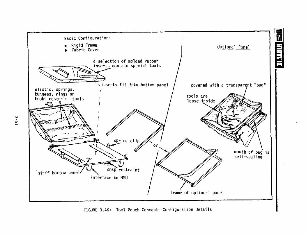
Basic Configuration:
* Rigid Frame Optional Panel* Fabric Cover
a selection of molded rubberinserts contain special tools
',inserts fit into bottom panel covered with a transparent "bag"elastic, springs,bungees, rings or tools arehooks restrain tools oos eloose inside
spring clipor
mouth of bag isself-sealing
stiff bottom panelinterface to MMU
frame of optional panel
FIGURE 3.46: Tool Pouch Concept--Configuration Details
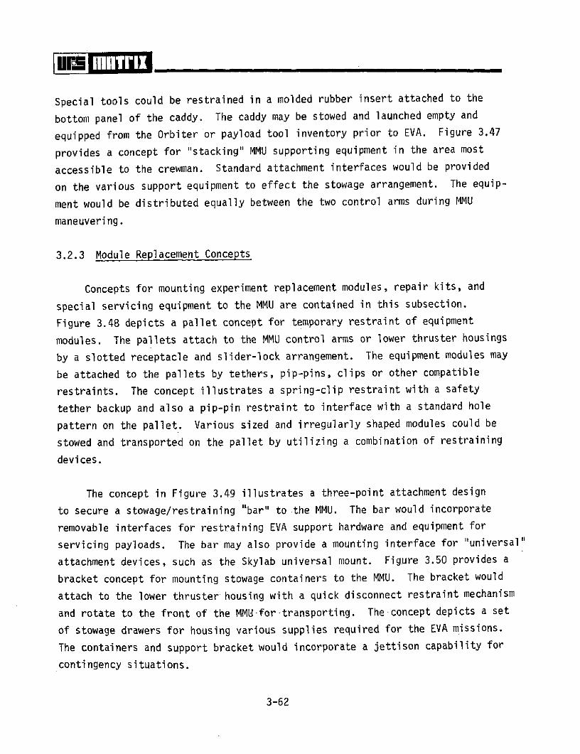
Special tools could be restrained in a molded rubber insert attached to the
bottom panel of the caddy. The caddy may be stowed and launched empty and
equipped from the Orbiter or payload tool inventory prior to EVA. Figure 3.47
provides a concept for "stacking" MMU supporting equipment in the area most
accessible to the crewman. Standard attachment interfaces would be provided
on the various support equipment to effect the stowage arrangement. The equip-
ment would be distributed equally between the two control arms during MMU
maneuvering.
3.2.3 Module Replacement Concepts
Concepts for mounting experiment replacement modules, repair kits, and
special servicing equipment to the MMU are contained in this subsection.
Figure 3.48 depicts a pallet concept for temporary restraint of equipment
modules. The pallets attach to the MMU control arms or lower thruster housings
by a slotted receptacle and slider-lock arrangement. The equipment modules may
be attached to the pallets by tethers, pip-pins, clips or other compatible
restraints. The concept illustrates a spring-clip restraint with a safety
tether backup and also a pip-pin restraint to interface with a standard hole
pattern on the pallet. Various sized and irregularly shaped modules could be
stowed and transported on the pallet by utilizing a combination of restraining
devices.
The concept in Figure 3.49 illustrates a three-point attachment design
to secure a stowage/restraining "bar" to the MMU. The bar would incorporate
removable interfaces for restraining EVA support hardware and equipment for
servicing payloads. The bar may also provide a mounting interface for "universal"
attachment devices, such as the Skylab universal mount. Figure 3.50 provides a
bracket concept for mounting stowage containers to the MMU. The bracket would
attach to the lower thruster housing with a quick disconnect restraint mechanism
and rotate to the front of the MMU.for-transporting. The concept depicts a set
of stowage drawers for housing various supplies required for the EVA missions.
The containers and support bracket would incorporate a jettison capability for
contingency situations.
3-62

Standard Interfaces Allow KitsTo Attach To Other SupportEquipment
Standard Interfaces
FIGURE 3.47: I4MU/EVA Support Equipment "Stacking" Concept

Module Or Stowage ContainerALSA
, .5 -Tether Rings (6)
A Perforated Plate
MMU
n Spring Clips Lugs
CONCEPT NO. 1
CONCEPT NO. 2 Pip-Pin
FIGURE 3.48: Ancillary Support Equipment Restraint Pallet Concept
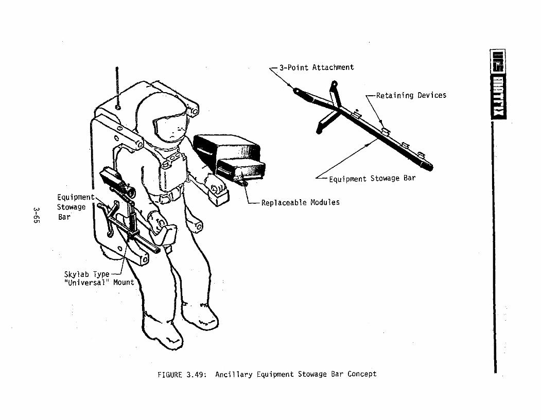
3-Point Attachment
Retaining Devices
Equipment Stowage Bar
EquipmentEqi e - Replaceable ModulesStowage
SBar
Skylab Type"Universal" Mount
FIGURE 3.49: Ancillary Equipment Stowage Bar Concept

ALSAModule/Parts Stowage
Attach Bracket
MMU
Container Adjusts ForCrewman Access
Bracket And Container Pivot ToFront Of Crewman For Translation
FIGURE 3.50: Orbital Systems Servicing Module Attachment Concept

3.2.4 Consumables Resupply Concept
Resupply of consumables to free-flying satellites may be an economical
payload application for the MMU. Figure 3.51 shows an arrangement for re-
supplying propellant from a stowage tank mounted on the MMU. The stowage
tank and support panel would be integrated to minimize external line routing
and connectors. The consumables resupply system would be mounted to the side
of the MMU prior to donning. The support panel would incorporate the necessary
hoses, quick disconnects and controls for effecting safe consumables transfer.
The support panel would also contain pressure gauges, warning indicators, etc..
for systems' status during resupply operations. The consumables resupply:
system would pivot 2700 about the forward attach point and attach to the
opposite control arm housing for MMU translation/maneuvers.
Figure 3.52 depicts an auxiliary MMU propellant stowage tank attachment
concept for extending the travel-maneuvering range. The tanks would be mounted
on each side of the MMU prior to crewman donning. Quick disconnect fittings
are provided for plumbing into the primary MMU propellant subsystem. Valving
for switching to the auxiliary propellant units is located for rapid access by,
the MMU crewman.
3.2.5 Data Acquisition Concepts
Figures 3.53 and 3.54 show concepts which provide mounting techniques
for attaching data acquisition equipment to the MMU. Figure 3.53 depicts a
concept for real-time experiment monitoring using a remote video system mounted
on the MMU. The system would utilize the same video components being considered
for free-flying teleoperator applications with modified equipment packaging for
the MMU interface. The data acquisition equipment would include a miniature
monitor for crewman-signal evaluation, data recording and video-signal relay
to the Orbiter. The data acquisition concept would also be applicable to
Orbiter and payload inspection and surveillance tasks.
3-67
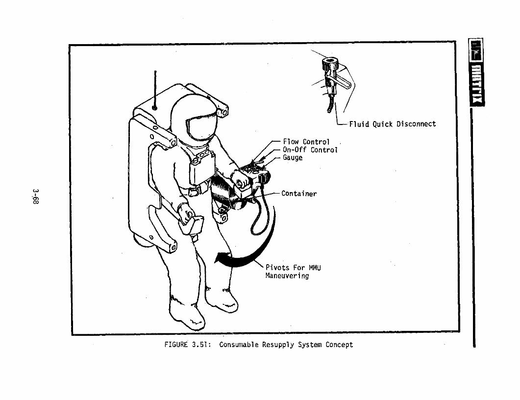
L Fluid Quick DisconnectFlow ControlOn-Off ControlGauge
Container
Pivots For MMUManeuvering
FIGURE 3.51: Consumable Resupply System Concept

GN2
Calfax Restraint
Flow Control
QD To MMU
FIGURE 3.52: MMU Auxiliary Propellant Stowage Concept
3-69

ALSA
Removable Camera
Control Panel-
S Universal Joint
Auxiliary Power Module Real-Time ExperimentMonitoring (Orbiter/Ground)
FIGURE 3.53: Data Acquisition Concept--Remote Video Inspection/Surveillance
AMPS Payload. ALSA
MMU -
MMU C rewman'
SInstrument
Release Instrument Package AndMechani-sm: -- -Control Concept
-FIGURE 354: Data Acquisitiori Euipment Con ept--Wake Detection and Measurement
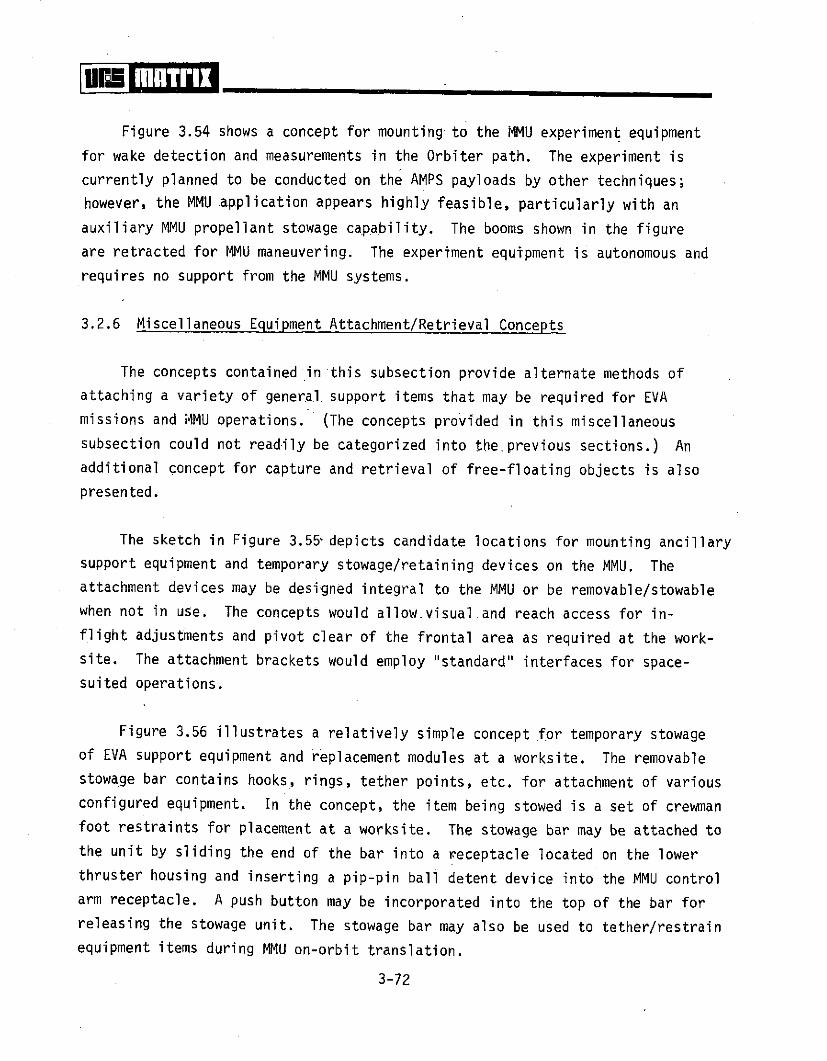
Figure 3.54 shows a concept for mounting to the MMU experiment equipment
for wake detection and measurements in the Orbiter path. The experiment is
currently planned to be conducted on the AMPS payloads by other techniques;
however, the MMU application appears highly feasible, particularly with an
auxiliary MMU propellant stowage capability. The booms shown in the figure
are retracted for MMU maneuvering. The experiment equipment is autonomous and
requires no support from the MMU systems.
3.2.6 Miscellaneous Equipment Attachment/Retrieval Concepts
The concepts contained in this subsection provide alternate methods of
attaching a variety of general support items that may be required for EVA
missions and MMU operations. (The concepts provided in this miscellaneous
subsection could not readily be categorized into theprevious sections.) An
additional concept for capture and retrieval of free-floating objects is also
presented.
The sketch in Figure 3.55 depicts candidate locations for mounting ancillary
support equipment and temporary stowage/retaining devices on the MMU. The
attachment devices may be designed integral to the MMU or be removable/stowable
when not in use. The concepts would allow.visual and reach access for in-
flight adjustments and pivot clear of the frontal area as required at the work-
site. The attachment brackets would employ "standard" interfaces for space-
suited operations.
Figure 3.56 illustrates a relatively simple concept for temporary stowage
of EVA support equipment and replacement modules at a worksite. The removable
stowage bar contains hooks, rings, tether points, etc. for attachment of various
configured equipment. In the concept, the item being stowed is a set of crewman
foot restraints for placement at a worksite. The stowage bar may be attached to
the unit by sliding the end of the bar into a receptacle located on the lower
thruster housing and inserting a pip-pin ball detent device into the MMU control
arm receptacle. A push button may be incorporated into the top of the bar for
releasing the stowage unit. The stowage bar may also be used to tether/restrain
equipment items during MMU on-orbit translation.
3-72
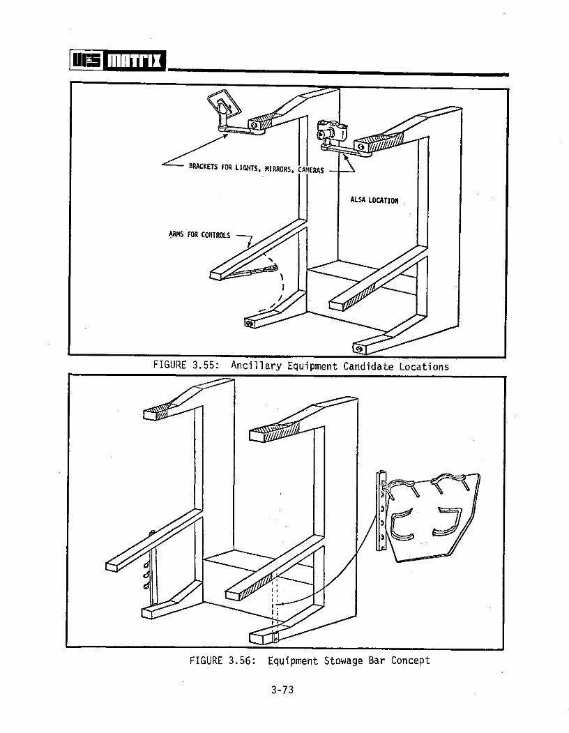
BRACKETS FOR LIGHTS, MIRRORS, CAMERAS
ALSA LOCATION
ARMS FOR CONTROLS
FIGURE 3.55: Ancillary Equipment Candidate Locations
FIGURE 3.56: Equipment Stowage Bar Concept
3-73

The concept shown in Figure 3.57 represents a computer programmed oper-
ations checklist displayed on a monitor for detailed on-orbit experiment systems
maintenance. The checklist procedures would be programmed on the Orbiter or at
a ground-based station and transmitted to the MMU attached monitor. The check-
list system would allow real-time repair and calibration operations to be per-
formed based on experimenter (located in the Orbiter or earth base) observations
and inputs. The MMU checklist system receiving unit with alphanumeric display
would allow the crewman to display any procedure required. A tape recorder
could be incorporated into the system for crew comments for later analysis.
The checklist system would mount to the MMU control arm and/or lower thruster
housing. The system would replace the mechanical checklists (document and
spacesuit cuff types) used on previous space programs.
Other less-sophisticated checklist concepts for MMU-EVA applications are
shown in, Figure 3.58. A "scroll" concept with the checklist printed on con-
tinuous rolls and displayed on a screen may be applicable where extensive
procedures are required for EVA operations. The proper checklist would be
inserted into the viewer prior to EVA. The viewer may be manually actuated
by hand cranks or electrically driven. A second concept would provide standard
loose-leaf checklists in a special binder. The binder would position the pages
for optimum viewing using a cam/spring mechanical system to automatically
position the pages.
The concept shown in Figure 3.59 depicts an extendible boom mounted to the
MMU for access to payload and Orbiter areas inaccessible to the MMU. The boom
could access areas to retrieve debris, open access doors, retrieve film data,
etc. End effectors for interfacing to various configurations would be stowed
with the boom system. The boom could be electrically actuated with manual backup
or purely mechanical. The mounting arrangement would provide sufficient latitude
to allow positioning the unit from an EVA worksite or MMU restraint. The boom
unit may also be applicable in transporting the MMU-crewman combination along
an extended worksite for inspection, monitoring or light force application
tasks.
3-74
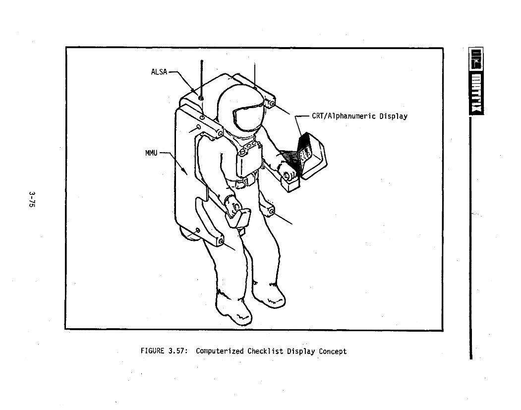
ALSA
CRT/Alphanumeric Display
MMU
FIGURE 3.57: Computerized Checklist Display Concept
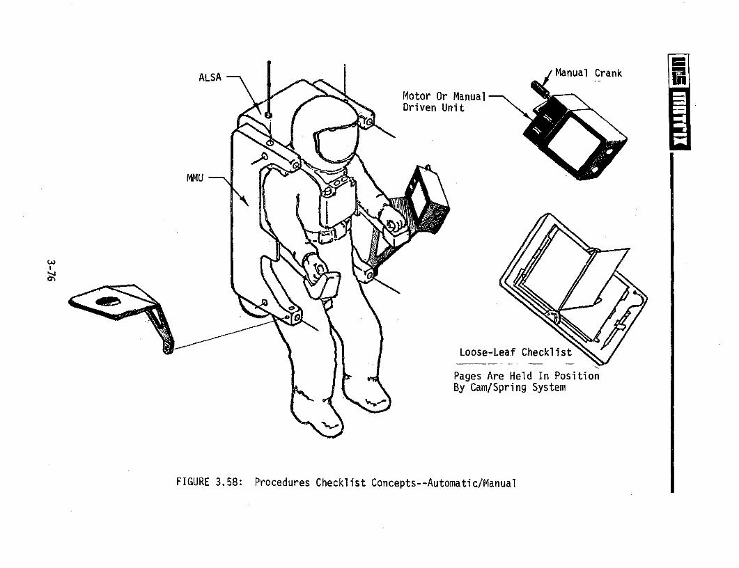
ALSA Manual Crank
Motor Or ManualDriven Unit
MMU
Loose-Leaf Checklist
Pages Are Held In PositionBy Cam/Spring System
FIGURE 3.58: Procedures Checklist Concepts--Automatic/Manual

ALSA
Handcranks(Backup)
Grappler
MMU
Extendible Boom System
Bracket Pivots ForMMU Maneuver
FIGURE 3.59: Extendible Boom System Concept

A basic method of equipment transfer on-orbit is the use of a stowage bag
or net. The concept depicted in Figure 3.60 utilizes a mesh bag for retrieval
and transfer of equipment ranging from space debris to personnel rescue systems
(PRS). The entrance to the net would be spring-loaded to open automatically by
tether line acutation. A "drawstring" device would be used to close the net
after equipment capture. An advantage of the capture net is the retrieval and
transfer of irregular shape and size objects not initially designed for on-
orbit retrieval. The crewman may be required to translate in the aft direction
while towing the net. Mirrors may be required to aid translation. The net
system will fold into a compact package for on-orbit stowage.
3-78
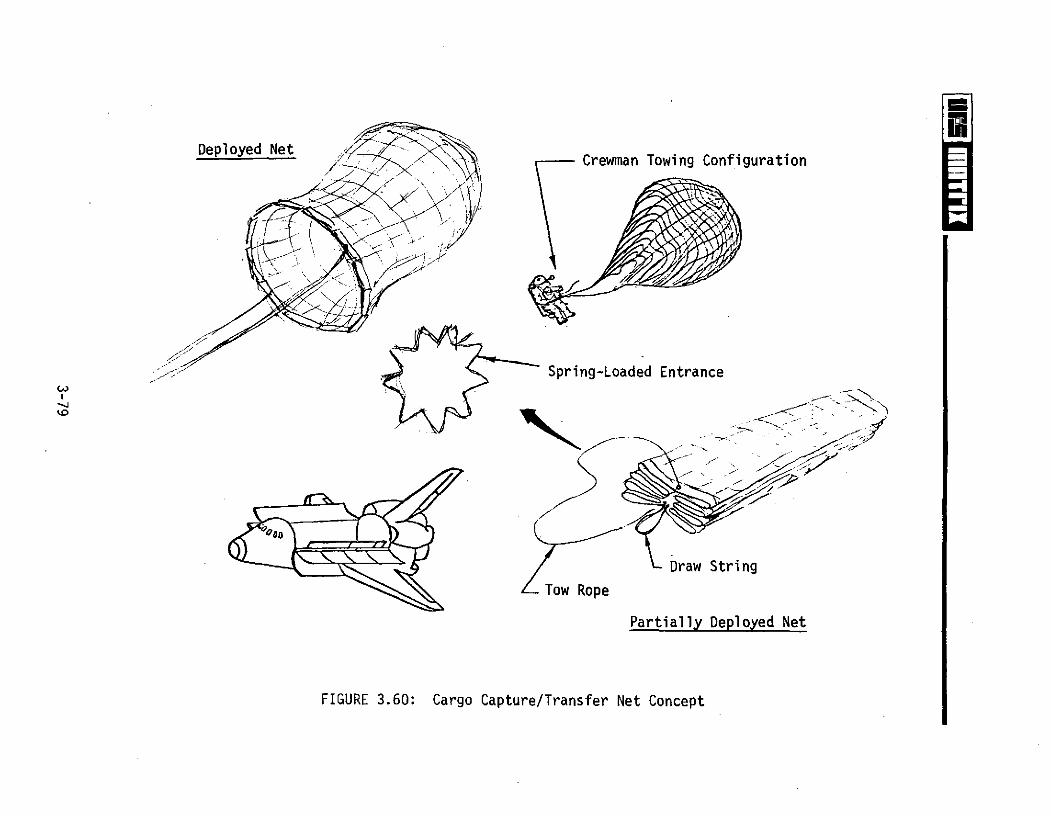
Deployed NetSCrewman Towing Configuration
- .-
Spring-Loaded Entrance
Draw String
Tow Rope
Partially Deployed Net
FIGURE 3.60: Cargo Capture/Transfer Net Concept

4.0 GENERAL MMU CONCLUSIONS AND RECOMMENDATIONS
Conclusions
This study has emphasized applications of the Manned Maneuvering Unit to
the Space Shuttle Program as providing a versatile utility capability to
support nominal.and contingency orbital operations (see Volume I). Ancillary
equipment concepts were developed to support the MMU-EVA operations and broaden
MMU applications. The study results conclude that the MMU, equipped with
appropriate support hardware and restraints, may be an essential and economical
entity of the U.S. space program orbital elements. While remote manipulator
systems and automation may provide feasible alternatives to performing EVA,
the physical interface between man and machine, human judgment and real-time
decision making are key factors in man versus machine selection. Man has fully
demonstrated, particularly during the Skylab Program, that he can be an integral
part of the spaceflight complex by adding the elements of judgment and reliability--
characteristics not provided by mechanical or automated systems alone.
Recommendations
The Manned Maneuvering Unit Mission Definition Study was performed in a
time frame when most Shuttle payloads were only in the conceptual design phase.
Preliminary analysis indicated that many of the mission payload planners and
designers are not cognizant of the potential capabilities of the MMU-EVA crewman
system relative to orbital applications. A program by NASA is recommended to
distribute available MMU physical, operational and performance characteristics/
data to the payload development community for consideration prior to payload
final design initiation. Designing for on-orbit servicing could become an
asset to many payloads.
The MMU attachment and ancillary equipment concept development effort was
performed using introductory artist concepts of the MMU prior to initiation of
MMU preliminary design. Therefore, the supporting systems conceptual designs
4-1

were developed, for integration into various interface configurations. The
conceptual design effort indicated that the following should be considered
during MMU preliminary design:
* Human factors engineering approach to operational interfaces
* Provide MMU external configuration to minimize visual and reach
restrictions
* Provide standardized interfaces for MMU restraint (launch/reentry, EMU)
and support equipment attachments
* Integrate utility connectors on the exterior of the.MMU (e.g., power,
propellant)
* Provide a capability for auxiliary propellant tanks and power supply.
In the design of MMU restraint and ancillary support equipment attachments,
the following should be considered:
* Provide an integrated, removable MMU service/restraint station to
include launch, service, don/doff and reentry
e Standardize support equipment attachment mechanisms and man-machine
interfaces, when possible
* Use space qualified off-the-shelf support equipment and attachment
devices, where applicable.
The following developmental programs are recommended to coincide with and/
or immediately follow the MMU preliminary design program to avoid possible MMU
systems redesign:
* Develop an AMU flight service/restraint station for mounting to the
Orbiter, payloads and pallets
* Conduct studies and/or develop adhesives and adhesive release
techniques for space application
4-2

e Develop Orbiter Thermal Protection System (TPS) repair kits for MMU
application
* Develop MMU and MMU-crewman combination worksite attachment mechanisms
* Develop EMU-to-MMU attachment system
* Conduct dynamic MMU cargo transfer (including PRS, EMU, MMU) simulations
to determine MMU transporting capabilities
* Conduct dynamic MMU-to-free-floating equipment simulations to determine
capture systems' design criteria.
Longer range MMU programs should include:
* Develop MMU navigation equipment for extended distance missions and
safety
* Adapt free-flying teleoperator video and data acquisition systems to
the MMU.
4-3