mann+hummel air cleaners - marind · respectiveaccessories–all havingtherenowned mann+hummeloem...
TRANSCRIPT

MANN+HUMMEL Air Cleaners

2
MANN+HUMMEL Industrial Filters
Close to you
Production facilities and salesoffices at various locations inEurope, America, SouthAmerica and in Asia enablethe clarification of technicalquestions locally. A subsidiarycompany or representativelocated near you means weare always available to offeryou assistance.
Modern, high performancevehicles, machines, devicesand engines require filtersand components with a corre-spondingly high performance.The documentation presentedhere will give you an overviewof our air cleaners and therespective accessories – allhaving the renownedMANN+HUMMEL OEMquality. Since our customersoperate in many varied fields,such as
• construction machines• agricultural machines• compressors• mechanical engineering• engines and gear units• commercial and customisedvehicles, etc.
MANN+HUMMEL has exten-sive experience elaboratingindividual concepts and solu-tions for your special field ofapplication.
Air cleaners for many fields of application
How to find your contactpartner:
If you are not yet in contactwith MANN+HUMMEL orone of our representatives,please call
Tel.: +49 (62 32) 53-80Fax: +49 (62 32) 53-88 99
and name your field of appli-cation. We will then pass youon to the appropriate salesteam.
Information is also availablein the internet at:www.mann-hummel.comE-Mail: [email protected]
automotive and other industries.A key area is high quality fil-tration products for vehicles,engines and industrial appli-cations. The OEM businesswith global market leadersand produc-ers of vehicles,machines and installationsdefines the quality and per-formance of the group. Filtersfor the international aftermar-
The MANN+HUMMEL Groupis an international companywith its headquarters inLudwigsburg, Germany.The group employs approx.11,500 people worldwide atmore than 40 locations.
The company develops, pro-duces and sells technicallycomplex components for the
ket are sold under numerousinternational brands as wellas under the MANN-FILTERbrand.
The Industrial Filters BusinessUnit with its headquarters inSpeyer, Germany is special-ised in meeting the require-ments of off-highway vehicleand - engine applications,
compressed air and vacuumtechnology, mechanicalengineering and plantconstruction. For theseand other industrial fieldsMANN+HUMMEL IndustrialFilters offers high perfor-mance products for thefiltration and separationof air, gases and liquids.

3
Contents
Company profile Page 2Contents Page 3Product overview Page 4
Europiclon® Page 9
NLG Page 23NLG Pico Page 24NLG Piclon Page 25NLG DualSpin® Combination air cleaners Page 25
Piclon Page 39
Pico-E Page 49
Oil-bath air cleaners Page 57
Inline Piclon Page 63
Picolino Page 67
Picolight Page 75
Oil-wetted air cleaners Page 79
Vacuum air cleaners Page 83
Air cleaners for two-way ventilation Page 87
Silencer cleaners Page 87
Accessories Page 93Brackets Page 95Rain caps Page 98Precleaners Page 100Air connecting parts Page 104Ejectors Page 112Service switches/service indicators Page 114
Technical Appendix Page 119
Glossary Page 120
Filter configuration Page 122
Servicing and installation instructions Page 126
Conversion table Page 128

4
Product overview
Page 9Two-stage plastic air cleaner0.8 m3/min to 28 m3/minContinuous: -40 °C to +80 °CFor short periods: +100 °CTangential inletStar-pleated element, centretube in the housing, radialseal, metal-freeSynthetic fabric element withcentre tube, radial seal, metal-freeFlexibility and economy withlonger service lifeConstruction and agriculturalmachines, mobile compressors
Europiclon®
DesignVolumetric flow rangeOperating temperature
Pre-separationMain element
Secondary element
Selection criteria
Typical applications
Page 24Single-stage plastic air cleaner10 m3/min to 50 m3/minContinuous: -40 °C to +80 °CFor short periods: +100 °CStar-pleated element with centretube, radial seal, metal-freeSynthetic fabric element withcentre tube, radial seal, metal-freeLow pressure drop and highlyeconomical with low dust loadsTrucks, mobile cranes, buses,stationary compressors, gen-erators
NLG PicoDesignVolumetric flow rangeOperating temperature
Main element
Secondary element
Selection criteria
Typical applications
NLG DualSpin® Combination air cleaners
Piclon
Europiclon®
NLG Piclon
Pico-E
NLG PicoPicolino
Picolight
Oil-wetted air cleaners
Filtrationrequ
iremen
ts/dus
tloa
d
0
high
medium
low
Flow rate V̇ [m3/min]10 20 30 40 50
Metal filters Plastic filters
Inline Piclon

NLG DualSpin®
Combination air cleanersDesignVolumetric flow rangeOperating temperature
Pre-separation
Main element
Secondary element
Selection criteria
Typical applications
5
Product overview
Page 25Two-stage plastic air cleaner10 m3/min to 40 m3/minContinuous: -40 °C to +80 °CFor short periods: +100 °CVane to generate air spinStar-pleated element with centretube, radial seal, metal-freeSynthetic fabric element withcentre tube, radial seal, metal-freeHighly economical with mediumdust loadsMobile compressors, mobilecranes, construction site trucks,construction and agriculturalmachines
NLG PiclonDesignVolumetric flow rangeOperating temperature
Pre-separationMain element
Secondary element
Selection criteria
Typical applications
Page 25Two-stage plastic air cleaner20 m3/min to 40 m3/minContinuous: -40 °C to +80 °CFor short periods: +100 °CExternal monocyclone with inte-grated pressure regeneration(DualSpin®)Star-pleated element with centretube, radial seal, metal-freeSynthetic fabric element withcentre tube, radial seal, metal-freeLong service life with heavydust conditionsCombine harvesters, fieldchoppers, harvesting machines,construction and agricultural ma-chines in very dusty conditions

6
Product overview
Page 39Two-stage metal air cleaner2 m3/min to 60 m3/minContinuous: -40 °C to +100 °CFor short periods: +120 °CVane to generate air spinStar-pleated element with centretube, axial seal, reinforced withmetalSynthetic fabric element withcentre tube, axial seal, rein-forced with metalLong service life with veryhigh mechanical stress on thehousingConstruction and agriculturalmachines, engine construction
PiclonDesignVolumetric flow rangeOperating temperature
Pre-separationMain element
Secondary element
Selection criteria
Typical applications
Page 49Single-stage metal air cleaner3 m3/min to 60 m3/minContinuous: -40 °C to +100 °CFor short periods: +120 °CStar-pleated element with centretube, axial seal, reinforced withmetalSynthetic fabric element withcentre tube, axial seal, rein-forced with metalLow pressure drop with veryhigh mechanical stress on thehousingCompressors, generators
Pico-EDesignVolumetric flow rangeOperating temperature
Main element
Secondary element
Selection criteria
Typical applications
Page 63Two-stage plastic air cleaner3 m3/min to 8 m3/minContinuous: -40 °C to +80 °CFor short periods: +100 °CVane to generate air spinStar-pleated element with centretube, axial seal, reinforced withmetalSynthetic fabric element withcentre tube, axial seal, rein-forced with metalLinear air flow when fitting toengine and medium dust loadsGeneral mechanical engineer-ing and vehicle construction
Inline PiclonDesignVolumetric flow rangeOperating temperature
Pre-separationMain element
Secondary element
Selection criteria
Typical applications

Page 79Single-stage air cleaner withouthousing1.4 m3/min to 87 m3/minContinuous: -30 °C to +100 °CFor short periods: +130 °CSteel mesh wetted with oil,radial sealStationary compressors, gen-erators, marine applications
Oil-wetted air cleanersDesign
Volumetric flow rangeOperating temperature
Filter element
Typical applications
7
Product overview
Page 67Single-stage plastic air cleaner0.15 m3/min to 3.2 m3/minContinuous: -30 °C to +100 °CFor short periods: +120 °CStar-pleated element, radialseal, metal-freeFilters for two-way ventilation,small engines, small pistoncompressors, general me-chanical engineering
PicolinoDesignVolumetric flow rangeOperating temperature
Filter element
Typical applications
Page 75Single-stage air cleaner withouthousing1 m3/min to 100 m3/minContinuous: -30 °C to +80 °CFor short periods: +100 °CStar-pleated element, radialseal, metal-freeStationary compressors, gen-erators, marine applications
PicolightDesign
Volumetric flow rangeOperating temperature
Filter element
Typical applications
Page 83Single-stage metal air cleaner0.7 m3/min to 12 m3/minContinuous: -30 °C to +80 °CFor short periods: +100 °CStar-pleated element with centretube, axial seal, reinforced withmetalAir and gas pipes with negativepressure (vacuum pumps)
Vacuum filtersDesignVolumetric flow rangeOperating temperature
Filter element
Typical applications

8

MANN+HUMMEL Europiclon®
Two-stage air cleaner – Modular system
9

These characteristics havemade the Europiclon® thetried and tested air cleanerfor all machines and equip-ment used in conditions with
The Europiclon® fromMANN+HUMMEL is charac-terised by its high dustcapacity and low pressuredrop.
10
medium to heavy dust loads.These include constructionand agricultural machines,mobile compressors andharvesting machines.
Advantages at a glance:
• long service life throughintegrated pre-separation
• highly economical throughmodular system
• extensive range of acces-sories
• corrosion free housing inimpact resistant plastic
pre-separation throughtangential inlet
Sectional view
• easy element change with-out tools
• highest operational reliabil-ity through elements withproven radial seal
• metal-free filter elementsare easily disposed of byincineration and thereforeare environmentally friendlywith inexpensive disposal
• easy adaptation to otherequipment with a flexiblebracket system
• patented filter elements
Europiclon® : The flexible allrounder
secondary element filter element dust discharge

11
Filter elements
The Europiclon® elements arefree of metal and thereforeeasily disposed of by inciner-ation. This enables inexpen-sive and environmentallyfriendly disposal of the usedelements.
Main element• high dust capacitythrough specialMANN+HUMMELfilter medium
• high reliabilitythrough radial sealon housing
• reliable pleat stabilityprevents pleats stickingtogether under demandingconditions
Secondary element• MANN+HUMMEL syntheticfabric allows a high safetymargin with low pressuredrop
• secure fit in housing pre-vents unintentional removalof the secondary element
Housing
The housing of theEuropiclon® is made of impactresistant polypropylene and issuitable for continuous use inthe temperature range - 40 °Cto +80 °C or for short periodsup to +100 °C.The external polygon designof the housing is recognis-able in the picture. TheEuropiclon® bracket, designedespecially for this structure,can be turned in incrementsof 5° opposite to the housing.
Depending on the air cleanersize, the housing can be turn-ed in the axial direction to sixdifferent locking positions.This offers the designer up to432 different fitting possibili-ties for the air cleaner. Inaddition, the wire clampswhich lock the air cleanerhousing can be placed in spe-cial pockets on the cap toadapt to special installationconditions.

12
Europiclon® 100 to 800Dimensions and part numbers
b2 t
d3
d1
h3
h1h2
d2b1
h4
Fig. 1Mirror image version of dirty airconnection available on request
1a 1b 1cCover with snap fasteners(just for 44 100 ...)
1a1b1c2a2b2c2a2b2c2a2b2c2a2b2c2a2b2c2c2c
withoutsecondary element44 100 92 91044 100 92 92044 100 92 94045 200 92 91045 200 92 92045 200 92 94045 300 92 91045 300 92 92045 300 92 94045 400 92 91045 400 92 92045 400 92 94045 500 92 91045 500 92 92045 500 92 94045 600 92 91045 600 92 92045 600 92 94045 700 92 94045 800 92 940
withsecondary element44 100 92 91144 100 92 92144 100 92 94145 200 92 91145 200 92 92145 200 92 94145 300 92 91145 300 92 92145 300 92 94145 400 92 91145 400 92 92145 400 92 94145 500 92 91145 500 92 92145 500 92 94145 600 92 91145 600 92 92145 600 92 94145 700 92 94145 800 92 941
Part No. Fig. Replacement filter elementNominalflow rate[m3/min]
Approx.weight[kg]
1 – 3
2 – 4.5
3 – 6
4 – 8
6 – 12
7.5 – 15
15 – 2118 – 28
C 11 100
C 14 200
C 15 300
C 16 400
C 20 500
C 23 610
C 25 710/3 *C 30 810/3
CF 100
CF 200
CF 300
CF 400
CF 500
CF 610
CF 710CF 810
0.9
1.7
2.1
3.0
3.8
5.0
6.09.0
MANN-FILTERsecondary element
MANN-FILTERmain element
* with spiral wound glue strip

13
Europiclon® 100 to 800Dimensions and part numbers
b2
b1 d2
d1
h4
h3
h2 h1
d3
t
2a 2b 2c 2dCover with wire clamps (for 45 200 ... to 45 800 ...)
Fig. 2Mirror image version of the dirty airconnection available on request
1a1b1c2a2b2c2a2b2c2a2b2c2a2b2c2a2b2c
2d
2d
withoutsecondary element44 100 92 91044 100 92 92044 100 92 94045 200 92 91045 200 92 92045 200 92 94045 300 92 91045 300 92 92045 300 92 94045 400 92 91045 400 92 92045 400 92 94045 500 92 91045 500 92 92045 500 92 94045 600 92 91045 600 92 92045 600 92 94045 700 92 940
45 800 92 940
withsecondary element44 100 92 91144 100 92 92144 100 92 94145 200 92 91145 200 92 92145 200 92 94145 300 92 91145 300 92 92145 300 92 94145 400 92 91145 400 92 92145 400 92 94145 500 92 91145 500 92 92145 500 92 94145 600 92 91145 600 92 92145 600 92 94145 700 92 941
45 800 92 941
Part No. Fig. Dimensions in mm (dimensions in inches)
b1
158(6.22)
173(6.81)
203(7.99)
223(8.78)
264(10.39)
295(11.61)
325(12.80)390
(15.35)
b2
45(1.77)
48(1.89)
59(2.32)
63(2.48)
73(2.87)
87(3.43)
92(3.62)114
(4.49)
d1
54(2.12)
62(2.44)
70(2.76)
82(3.23)
102(4.02)
110(4.33)
132(5.20)150
(5.91)
d2
50(1.97)
60(2.36)
70(2.76)
80(3.15)
100(3.94)
110(4.33)
130(5.12)150
(5.91)
d3
188(7.40)
198(7.80)
228(8.98)
248(9.76)
288(11.34)
323(12.72)
353(13.90)418
(16.46)
h1
260(10.24)
327(12.87)
367(14.45)
383(15.08)
408(16.06)
414(16.30)
548(21.57)598
(23.54)
h2
27(1.06)
27(1.06)
30(1.18)
32(1.26)
37(1.46)
27(1.06)
32(1.26)32
(1.26)
h3
38(1.50)
42(1.65)
45(1.77)
52(2.05)
62(2.44)
65(2.56)
76(2.99)85
(3.35)
h4
104(4.09)
112(4.41)
135(5.32)
144(5.67)
174(6.85)
190(7.48)
212(8.35)241
(9.49)
t
237(9.39)
304(11.97)
344(13.54)
359(14.13)
384(15.12)
384(15.12)
500(19.69)550
(21.65)

4410
0 ...
4560
0 ...45
700 ...
4580
0 ...
4550
0 ...45
400..
.
4530
0 ...
4520
0 ...
... for flow rates as per ISO 5011
... for dust capacity as per ISO 5011 with SAE coarse test dust
Flow
resis
tance[mbar]
Flow
resis
tance[mbar]
Volume flow V̇[m3/min]
Dust capacity [g]
Flow
resis
tance[mbar]
Flow
resis
tance[mbar]
Flow
resis
tance[mbar]
Flow
resis
tance[mbar]
Flow
resis
tance[mbar]
44 100 92 9.0 – 3.0 m3/min.
45 200 92 9.0 – 4.5 m3/min.
45 300 92 9.0 – 6.0 m3/min.
45 600 92 9.0 – 15.0 m3/min.
45 500 92 9.0 – 12.0 m3/min.
45 400 92 9.0 – 8.0 m3/min.
0 200 400 600 800 1000 1200 1400 1600 1800
14
Europiclon® 100 to 800Flow characteristics without secondary element ...
45 700 92 9.0 – 21.0 m3/min.
45 800 92 9.0 – 28.0 m3/min.
80706050403020100
Dust capacity [g]0 500 1000 1500 2000 2500 3000
80706050403020100
80706050403020100
Dust capacity [g]0 1000 2000 3000 4000 5000 6000
80706050403020100
80706050403020100
80706050403020100
Dust capacity [g]0 1000 2000 3000 4000 5000 6000 7000 8000
Dust capacity [g]0 2000 4000 6000 8000 10000 12000
Dust capacity [g]0 20004000 8000 12000 16000 20000
Flow
resis
tance[mbar]
Flow
resis
tance[mbar]80
706050403020100
Dust capacity [g]0 1000 2000 3000 4000 5000 6000
80706050403020100
Dust capacity [g]0 5000 10000 15000 20000 25000 30000
50
302015
10
5
432
1
0.10.1 1 2 3 4 5 678 10 1520 30 40

4410
0 ...
4560
0 ...45
700 ...
4580
0 ...
4550
0 ...
4540
0...
4530
0 ...
4520
0 ...
... for flow rates as per ISO 5011
Flow
resis
tance[mbar]
Volume flow V̇[m3/min]
44 100 92 9.1 – 3.0 m3/min.
45 200 92 9.1 – 4.5 m3/min.
45 300 92 9.1 – 6.0 m3/min.
45 600 92 9.1 – 15.0 m3/min.
45 500 92 9.1 – 12.0 m3/min.
45 400 92 9.1 – 8.0 m3/min.
15
Europiclon® 100 to 800Flow characteristics with secondary element ...
... for dust capacity as per ISO 5011 with SAE coarse test dust
45 700 92 9.1 – 21.0 m3/min.
45 800 92 9.1 – 28.0 m3/min.
Flow
resis
tance[mbar]
Dust capacity [g]
Flow
resis
tance[mbar]
Flow
resis
tance[mbar]
Flow
resis
tance[mbar]
Flow
resis
tance[mbar]
Flow
resis
tance[mbar]
0 200 400 600 800 1000 1200 1400 1600
80706050403020100
Dust capacity [g]0 500 1000 1500 2000 2500
80706050403020100
80706050403020100
Dust capacity [g]0 1000 2000 3000 4000 5000
80706050403020100
80706050403020100
80706050403020100
Dust capacity [g]0 1000 2000 3000 4000 5000 6000 7000 8000
Dust capacity [g]0 2000 4000 6000 8000 10000 12000
Dust capacity [g]0 2000 4000 6000 8000 12000 16000
Flow
resis
tance[mbar]
Flow
resis
tance[mbar]80
706050403020100
Dust capacity [g]0 1000 2000 3000 4000 5000 6000
80706050403020100
Dust capacity [g]0 5000 10000 15000 20000 25000 30000
50
30
2015
10
54
3
2
11 2 3 4 5 6 7 8 10 1520 30 40

16
The new Europiclon® 50 fromMANN+HUMMEL extendsthe range of the successfulEuropiclon® line to enginesand equipment with a powerrating up to 20 kW.Along with the known advan-tages of the Europiclon® linewhich include reliability, longservice life and its robust,corrosion-free housing, thenew Europiclon® 50 has anumber of additional featureswhich offer important advan-tages for the designer anduser.
Advantages at a glance:
• twelve-position clean airoutlet with integratedconnection for serviceindicator or switch
• clean air outlet availablewith straight pipe connec-tion or with a 90° elbow
• new space-saving turn-lockfastener and easy filter ele-ment change without tools
• especially low pressuredrop also in operation withfitted secondary element
• cost-effective
Europiclon® 50
The new filter elements forthe Europiclon® 50 offer highperformance and are cost-effective. The radial sealused for the main element inconnection with the specialpleat stabilisation enables ahigh separation efficiency ofmore than 99.95% and ahigh dust capacity. A furtheradvantage is the patentedMANN+HUMMEL productiontechnology where the sealand the element end platesare manufactured in oneprocess step using specialelastomers.
A plastic centre tube in thehousing provides good sup-port for the element withoutnegatively influencing thewithdrawal distance.
A secondary element protectsthe engine during a filter ser-vice or if the main element isdamaged. It is an importantcomponent for comprehensiveengine protection, which en-sures the maximum service
life of your machine. Thesecondary element of the newEuropiclon® 50 consists of aspecial synthetic fabric, aplastic centre tube and a radi-al seal in PUR foam. The filtersurface area is approx. 45%larger than comparable prod-ucts from the competition.This leads to minimal pres-sure drop with an increase inthe service life of the filter.
Filter elements

17
The Europiclon® 50 bracketoffers flexibility during instal-lation with 16 different avail-able positions around its cir-cumference and two possiblelocking positions in the axialdirection.The special polygon designis matched to the air cleanerhousing and ensures that theair cleaner fits securely in thebracket.
Bracket
On the clean air side the newEuropiclon® 50 is equippedwith a twelve-position cleanair outlet. This port is availa-ble in a straight pipe ver-sion or with a 90° elbow.As the hanging installationposition is not recommendedfor the service switch,MANN+HUMMEL offers the90° elbow in two versions.Before placing your order,please check to see whichorientation is more appro-priate for your installationconditions.
Clean air outlet
270° 270°
270°

18
Europiclon® 50Dimensions and part numbers
90° elbowFig. 1
Straight pipeFig. 2
90° elbowFig. 3
withoutsecondary element
44 058 92 91044 058 92 92044 050 92 91044 050 92 92044 059 92 91044 059 92 920
withsecondary element
44 058 92 91144 058 92 92144 050 92 91144 050 92 92144 059 92 91144 059 92 921
Part No. Replacement filter elementMANN-FILTERmain element
C 10 050
C 10 050
C 10 050
MANN-FILTERsecondary element
CF 50
CF 50
CF 50
Approx.weight[kg]
0.7
0.7
0.7
Nominalflow rate[m3/min]
0.8 – 2
0.8 – 2
0.8 – 2
OBEN TOP
OPENCLOSE
/
55.3(2.18)
199.8(7.87)
VersionClean airoutlet
112233
VersionDust
discharge
545454
Fig. 4
Fig. 5
37(1.46) 165
(6.50)
ø 144(5.67)
ø 45(1.75)
M 10x1
ø 45(1.75)
ø 124(4.88)
83(3.27)

19
Europiclon® 50Flow characteristics ...
... for flow rates as per ISO 5011 with straight pipe
Volume flow V̇ [m3/min]
Flow
resis
tance[mbar]
0 1 2 3
... for dust capacity as per ISO 5011 with straight pipewith secondary element ...
Dust capacity PTI coarse [g]
Flow
resis
tance[mbar]
0 200 400 600 800 1000 1200 1400
... for dust capacity as per ISO 5011 with 90° elbowwith secondary element ...
Dust capacity PTI coarse [g]
Flow
resis
tance[mbar]
0 200 400 600 800 1000 1200
... for dust capacity as per ISO 5011 with straight pipewithout secondary element ...
Dust capacity PTI coarse [g]
Flow
resis
tance[mbar]
0 200 400 600 800 1000 1200 1400
... for dust capacity as per ISO 5011 with 90° elbowwithout secondary element ...
Dust capacity PTI coarse [g]
Flow
resis
tance[mbar]
0 200 400 600 800 1000 1200 1400
EP 50 with SE
EP 50 without SE
... for flow rates as per ISO 5011 with 90° elbow
Volume flow V̇ [m3/min]Flow
resis
tance[mbar]
0 1 2 3
50
40
30
20
10
0
50
40
30
20
10
0
EP 50 with SE
EP 50 without SE
Volume flow: 1.7 m3/min.80
70
60
50
40
30
20
10
0
Volume flow: 1.7 m3/min.80
70
60
50
40
30
20
10
0
Volume flow: 1.7 m3/min.
Volume flow: 1.7 m3/min.
80
70
60
50
40
30
20
10
0
80
70
60
50
40
30
20
10
0

the surroundings. The func-tionality of the pre-separationremains exactly the same.The dust is separated reliablyinto the dust collector and isemptied manually from timeto time. The timing of the ser-vice intervals depends on theapplication conditions.
Your MANN+HUMMEL part-ner will be happy to answerany questions on this version.
The Europiclon® with a dustcollector is especially suitablefor applications where the dustdischarge process should notdirty the immediate surround-ings, e.g. as a requirementfor production equipment. Atthe same time the service lifeadvantages of a two-stageair cleaner are still valid. Inthese conditions the cover ofthe Europiclon® is fitted witha dust collector and sealed to
20
Special versionsEuropiclon® with dust collector (sizes 100 to 800)
b1 d2
h4
h2 h1
h3
d1
d3
t
Fig. 1 Cover with snap fasteners(only 44 100 ...)
Fig. 2 Cover with wire clamps(45 200 ... to 45 800 ...)
12222222
withoutsecondary element44 100 92 95045 200 92 95045 300 92 95045 400 92 95045 500 92 95045 600 92 95045 700 92 95045 800 92 950
withsecondary element44 100 92 95145 200 92 95145 300 92 95145 400 92 95145 500 92 95145 600 92 95145 700 92 95145 800 92 951
MANN-FILTERmain element
MANN-FILTERsecondary element
Part No. Fig. Replacement filter elementNominalflow rate[m3/min]
1 – 32 – 4.53 – 64 – 86 – 127.5 – 1514 – 2118 – 28
C 11 100C 14 200C 15 300C 16 400C 20 500C 23 610C 25 710C 30 810
CF 100CF 200CF 300CF 400CF 500CF 610CF 710CF 810
Dimensions and air cleaner specifications identical to types... 920/921, see page 13

Dimensions identical to types ... 920/921,see page 13
21
Special versionsEuropiclon® for vacuum applications (sizes 100 to 600)
Specially modified filter typesare available for use withvacuum applications.
Typical applications are vacu-um lifting devices and othernegative pressure systems.
b1 d2
h4
h2 h1
h3
d1
d3
t
Fig. 1 Cover with snap fastener(only 44 180 ...)
Fig. 2 Cover with wire clamps(45 280 ... to 45 680 ...)
4418
0 9296
0
4568
0 9296
0
4558
0 9296
0
4548
0 9296
0
4538
0 9296
0
4528
0 9296
0
50
40
30
20
10
31 2 3 4 5 6 7 8 9 10 15 20 30
4
56Fl
owresis
tance[mbar]
Volume flow V̇ [m3/min]
122222
withoutsecondary element44 180 92 96045 280 92 96045 380 92 96045 480 92 96045 580 92 96045 680 92 960
MANN-FILTERmain elementC 11 100C 14 200C 15 300C 16 400C 20 500C 23 610
Part No. Fig. Nominalflow rate[m3/min]
1 – 32 – 4.53 – 64 – 86 – 127.5 – 15
Replacement filter element
22
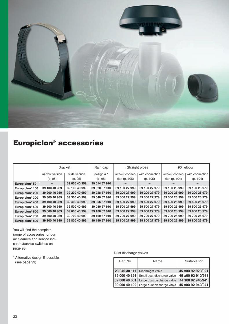
Europiclon® accessories
Europiclon® 50Europiclon® 100Europiclon® 200Europiclon® 300Europiclon® 400Europiclon® 500Europiclon® 600Europiclon® 700Europiclon® 800
narrow version
(p. 95)
–39 100 40 98939 200 40 98939 300 40 98939 400 40 98939 500 40 98939 600 40 98939 700 40 98939 800 40 989
wide version
(p. 95)
39 050 40 95939 100 40 99939 200 40 99939 300 40 99939 400 40 99939 500 40 99939 600 40 99939 700 40 99939 800 40 999
Bracket
without connec-
tion (p. 105)
–39 100 27 99939 200 27 99939 300 27 99939 400 27 99939 500 27 99939 600 27 99939 700 27 99939 800 27 999
with connection
(p. 105)
–39 100 27 97939 200 27 97939 300 27 97939 400 27 97939 500 27 97939 600 27 97939 700 27 97939 800 27 979
Straight pipes 90° elbowRain cap
design A *
(p. 98)
39 014 67 91039 020 67 91039 028 67 91039 040 67 91039 056 67 91039 080 67 91039 100 67 91039 160 67 91039 190 67 910
without connec-
tion (p. 104)
–39 100 25 99939 200 25 99939 300 25 99939 400 25 99939 500 25 99939 600 25 99939 700 25 99939 800 25 999
with connection
(p. 104)
–39 100 25 97939 200 25 97939 300 25 97939 400 25 97939 500 25 97939 600 25 97939 700 25 97939 800 25 979
You will find the completerange of accessories for ourair cleaners and service indi-cators/service switches onpage 93.
* Alternative design B possible(see page 99)
23 040 30 11139 000 40 39139 000 40 66139 000 40 102
Part No.
Diaphragm valve
Small dust discharge valve
Large dust discharge valve
Large dust discharge valve
Name
45 x00 92 920/92145 x00 92 910/91144 100 92 940/94145 x00 92 940/941
Suitable for
Dust discharge valves

MANN+HUMMEL NLGModular air cleaner systemfor a wide range of applications
23

• corrosion-free and robusthousing through use ofplastic reinforced with fibre-glass
• the Piclon version with inte-grated dust pre-separationcan also be used with me-dium to heavy dust loads
• as a combination aircleaner with DualSpin®
precleaner also suitablefor very difficult dust con-ditions due to its longservice life
• metal-free filter elementsare easily disposed of by
The new NLG line fromMANN+HUMMEL offers aflexible and economic so-lution for many variedapplications in the fieldof intake air filtration.
Advantages at a glance:
• high flexibility throughvariable modular system
• economic air cleanersystem through modulardesign
• easy element changewithout tools
24
incineration and thereforeare environmentally friendlywith inexpensive disposal
• problem-free adaptation toother equipment through
variable connection posi-tions
• quick first-fit on the vehiclethrough threaded inserts
• patented filter elements
NLG: Flexible – Robust – Economical
NLG PicoSingle-stage air cleaners
clean air outlet
housing in plasticreinforced withfibre-glass
dirty air connection
Pico filter element
secondary element(optional)
water dischargevalve on the housing;not shown here
The Pico is the single-stageversion of the NLG, i.e.without integrated dust pre-separation. It is particularlysuitable for applications withlow dust loads where minimalpressure drop in the air clean-er is a special requirement.
These are, for example:• commercial vehicles(trucks)
• buses• mobile cranes• compressors• stationary engines• generators• marine applications

The combination air cleanersconsist of Pico versions ofthe NLG air cleaner in size37 and the new DualSpin®
precleaners specially devel-oped for these air cleanerswhich have an efficiency ofmore than 90% with a lowpressure drop. Due to itslong service and special ver-sion of the precleaner, whereclogging is almost unheardof, the combination air clean-ers are suitable for use withmost applications in verydusty conditions.
These include, for example:• combine harvesters• field choppers• special harvesting ma-chines, e.g. for cotton,sugar cane or peat
• construction and agricul-tural machines in verydusty conditions
You can configure the com-bination air cleaner exactlyaccording to the service lifeyou require and the air re-quirement of the machine.There are three housinglengths available for the aircleaner and two versions ofthe precleaner for volumeflows between 20 m3/min and40 m3/min.
NLG DualSpin® Combination air cleanersTwo-stage air cleaners with external pre-separation
NLG PiclonTwo-stage air cleaners with integrated pre-separation
The Pico and Piclon versionsboth have identical housingand connection dimensions.Therefore the Piclon can re-place the Pico if the use of amachine in a certain regionrequires a special version.In this situation changing theair cleaner does not requiremaking any changes to thepipe connections or to thefixing of the air cleanerbracket.
clean air outlet
housing in plasticreinforced withfibre-glass
dirty air connection
integrated dustprecleaner
Piclon filter element
secondary elementavailable; not shownhere
dust discharge valve
The Piclon version is thetwo-stage version of the NLGwith integrated dust pre-separation and an efficiencyof more than 75%. It is partic-ularly suitable for applicationswith medium to heavy dustloads.
These are, for example:• construction and agricul-tural machines
• all typical Pico applicationswith a requirement forlonger service life
clean air outlet
housing in plasticreinforced withfibre-glass
bracket
dust discharge
Pico filter element
secondary element
25
26
Modular system
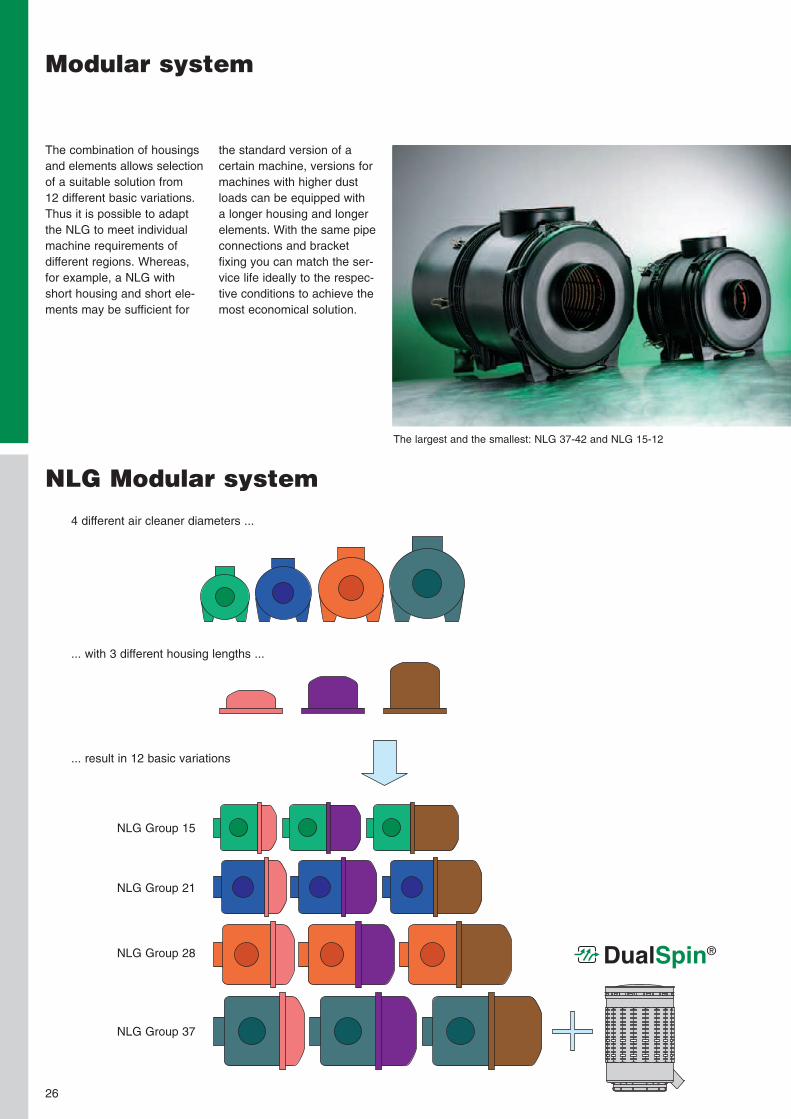
the standard version of acertain machine, versions formachines with higher dustloads can be equipped witha longer housing and longerelements. With the same pipeconnections and bracketfixing you can match the ser-vice life ideally to the respec-tive conditions to achieve themost economical solution.
The combination of housingsand elements allows selectionof a suitable solution from12 different basic variations.Thus it is possible to adaptthe NLG to meet individualmachine requirements ofdifferent regions. Whereas,for example, a NLG withshort housing and short ele-ments may be sufficient for
The largest and the smallest: NLG 37-42 and NLG 15-12
NLG Modular system
4 different air cleaner diameters ...
... with 3 different housing lengths ...
... result in 12 basic variations
NLG Group 15
NLG Group 21
NLG Group 28
NLG Group 37
DualSpin®

DualSpin®
27
Filter elements
NLG Filter element
• high dust capacity throughMANN+HUMMEL gradedmedium
• robust design with plasticcentre tube
• patented design• element protection due tointegrated handle preventsdamage during filter change
NLG Secondary element
• MANN+HUMMEL syntheticfabric for high separationefficiency with low pressuredrop
• secure fit in housing withscrew fitting which furtherprotects the engine asthis prevents unintentionalremoval of the secondaryelement
• robust design with plasticcentre tube
MANN+HUMMEL has devel-oped a precleaner especiallydesigned for the NLG aircleaner. The DualSpin® issuitable for use in very diffi-cult operating conditions, suchas harvesting applications.
Advantages of theDualSpin® precleaner:
• high pre-separation effi-ciency with low pressuredrop
• the housing is made fromspecial antistatic plasticwhich is very suitable fororganic particles
• various distributor insertscan be used to adapt thepre-cyclone perfectly tothe air requirement of themachine
• the polygon structure ofthe housing exterior allowsuse of the proven bracketof the Europiclon® 700(Part No. 39 700 40 999)
DualSpin® Precleaner
28
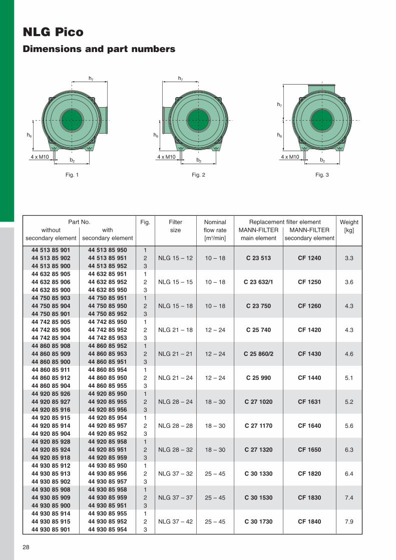
NLG PicoDimensions and part numbers
withoutsecondary element
44 513 85 90144 513 85 90244 513 85 90044 632 85 90544 632 85 90644 632 85 90044 750 85 90344 750 85 90444 750 85 90144 742 85 90544 742 85 90644 742 85 90444 860 85 90844 860 85 90944 860 85 90044 860 85 91144 860 85 91244 860 85 90444 920 85 92644 920 85 92744 920 85 91644 920 85 91544 920 85 91444 920 85 90444 920 85 92844 920 85 92444 920 85 91844 930 85 91244 930 85 91344 930 85 90244 930 85 90844 930 85 90944 930 85 90044 930 85 91444 930 85 91544 930 85 901
withsecondary element
44 513 85 95044 513 85 95144 513 85 95244 632 85 95144 632 85 95244 632 85 95044 750 85 95144 750 85 95044 750 85 95244 742 85 95044 742 85 95244 742 85 95344 860 85 95244 860 85 95344 860 85 95144 860 85 95444 860 85 95044 860 85 95544 920 85 95044 920 85 95544 920 85 95644 920 85 95444 920 85 95744 920 85 95244 920 85 95844 920 85 95144 920 85 95944 930 85 95044 930 85 95644 930 85 95744 930 85 95844 930 85 95944 930 85 95144 930 85 95544 930 85 95244 930 85 954
Part No. Nominalflow rate[m3/min]
10 – 18
10 – 18
10 – 18
12 – 24
12 – 24
12 – 24
18 – 30
18 – 30
18 – 30
25 – 45
25 – 45
25 – 45
Replacement filter elementMANN-FILTERmain element
C 23 513
C 23 632/1
C 23 750
C 25 740
C 25 860/2
C 25 990
C 27 1020
C 27 1170
C 27 1320
C 30 1330
C 30 1530
C 30 1730
MANN-FILTERsecondary element
CF 1240
CF 1250
CF 1260
CF 1420
CF 1430
CF 1440
CF 1631
CF 1640
CF 1650
CF 1820
CF 1830
CF 1840
Fig.
123123123123123123123123123123123123
Filtersize
NLG 15 – 12
NLG 15 – 15
NLG 15 – 18
NLG 21 – 18
NLG 21 – 21
NLG 21 – 24
NLG 28 – 24
NLG 28 – 28
NLG 28 – 32
NLG 37 – 32
NLG 37 – 37
NLG 37 – 42
b2
h7
h6
4 x M10 b2
h6
h7
4 x M10b2
h7
h6
4 x M10
Fig. 1 Fig. 2 Fig. 3
Weight[kg]
3.3
3.6
4.3
4.3
4.6
5.1
5.2
5.6
6.3
6.4
7.4
7.9

h1
h2
h5
b1
d2
d3
d4
h3
h4
d1
t1t2
29
NLG PicoDimensions and part numbers
Group
15
21
28
37
Dimensions in mm (dimensions in inches)Filtersize
NLG 15-12NLG 15-15NLG 15-18
NLG 21-18NLG 21-21NLG 21-24
NLG 28-24NLG 28-28NLG 28-32
NLG 37-32NLG 37-37NLG 37-42
d1
130(5.12)
150(5.91)
180(7.09)
210(8.27)
d2
110(4.33)
130(5.12)
150(5.91)
180(7.09)
d3
299(11.77)
339(13.35)
365(14.37)
407(16.02)
d4
285(11.22)
323(12.72)
349(13.74)
393(15.47)
b1
140(5.51)
175(6.89)
210(8.27)
245(9.65)
b2
200(7.87)
200(7.87)
200(7.87)
240(9.45)
h1
305(12.01)360
(14.17)415
(16.34)365
(14.37)415
(16.34)465
(18.31)427
(16.81)480
(18.90)533
(20.98)498
(19.61)563
(22.17)628
(24.72)
h2
228(8.98)
260(10.24)
295(11.61)
363(14.29)
h3
33(1.30)
33(1.30)
33(1.30)
33(1.30)
h4
120(4.72)
145.5(5.73)
163(6.42)
188(7.40)
h5
91(3.59)
91(3.59)
91(3.59)
91(3.59)
h6
153(6.02)
173(6.81)
185(7.28)
207(8.15)
h7
182(7.17)
203(7.99)
215(8.46)
237(9.33)
t1
230(9.06)
260(10.24)
296(11.65)
364(14.33)
t2
273(10.75)328
(12.91)383
(15.08)332
(13.07)382
(15.04)432
(17.01)395
(15.55)448
(17.64)501
(19.72)465
(18.31)530
(20.87)595
(23.43)
30
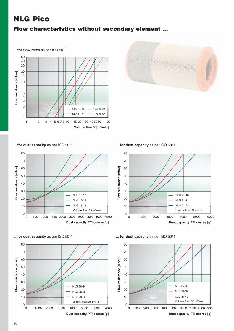
NLG PicoFlow characteristics without secondary element ...
... for flow rates as per ISO 5011
Volume flow V̇ [m3/min]
Flow
resis
tance[m
bar]
5040
30
2015
10
543
2
11 2 3 4 5 6 7 8 10 15 20 30 405060 100
NLG 15-15
NLG 21-21
NLG 28-28
NLG 37-37
... for dust capacity as per ISO 5011
Dust capacity PTI coarse [g]
Flow
resis
tance[m
bar]
80
70
60
50
40
30
20
10
00 500 1000 1500 2000 2500 3000 3500 4000 4500
... for dust capacity as per ISO 5011
Dust capacity PTI coarse [g]
Flow
resis
tance[m
bar]
0 1000 2000 3000 4000 5000 6000
... for dust capacity as per ISO 5011
Dust capacity PTI coarse [g]
Flow
resis
tance[m
bar]
0 1000 2000 3000 4000 5000 6000 7000
NLG 28-24
NLG 28-28
NLG 28-32
Volume flow: 28 m3/min
... for dust capacity as per ISO 5011
Dust capacity PTI coarse [g]
Flow
resis
tance[m
bar]
0 1000 2000 3000 4000 5000 6000 7000 8000 9000
NLG 37-32
NLG 37-37
NLG 37-42
Volume flow: 37 m3/min
NLG 15-12
NLG 15-15
NLG 15-18
Volume flow: 15 m3/min
NLG 21-18
NLG 21-21
NLG 21-24
Volume flow: 21 m3/min
80
70
60
50
40
30
20
10
0
80
70
60
50
40
30
20
10
0
80
70
60
50
40
30
20
10
0

31
NLG PicoFlow characteristics with secondary element ...
... for flow rates as per ISO 5011
Volume flow V̇ [m3/min]
Flow
resis
tance[m
bar]
5040
30
2015
10
543
2
11 2 3 4 5 6 7 8 10 15 20 30 40 506070
... for dust capacity as per ISO 5011
Dust capacity PTI coarse [g]
Flow
resis
tance[m
bar]
80
70
60
50
40
30
20
10
00 500 1000 1500 2000 2500 3000 3500 4000 4500
... for dust capacity as per ISO 5011
Dust capacity PTI coarse [g]
Flow
resis
tance[m
bar]
0 500 1000 1500 2000 2500 3000 3500 4000 4500 5000
... for dust capacity as per ISO 5011
Dust capacity PTI coarse [g]
Flow
resis
tance[m
bar]
0 1000 2000 3000 4000 5000 6000 7000
NLG 28-24
NLG 28-28
NLG 28-32
Volume flow: 28 m3/min
... for dust capacity as per ISO 5011
Dust capacity PTI coarse [g]
Flow
resis
tance[m
bar]
0 1000 2000 3000 4000 5000 6000 7000 8000 9000
NLG 37-32
NLG 37-37
NLG 37-42
Volume flow: 37 m3/min
NLG 15-15
NLG 21-21
NLG 28-28
NLG 37-37
NLG 15-12
NLG 15-15
NLG 15-18
Volume flow: 15 m3/min
NLG 21-18
NLG 21-21
NLG 21-24
Volume flow: 21 m3/min
80
70
60
50
40
30
20
10
0
80
70
60
50
40
30
20
10
0
80
70
60
50
40
30
20
10
0

32
NLG PiclonDimensions and part numbers
withoutsecondary element
44 526 92 90044 526 92 90144 526 92 90244 625 92 90144 625 92 90244 625 92 90044 722 92 90544 722 92 90644 722 92 90444 722 92 90744 722 92 90844 722 92 90344 920 92 90644 920 92 90744 920 92 90244 920 92 90844 920 92 90944 920 92 90344 930 92 90244 930 92 90344 930 92 90044 930 92 90444 930 92 90544 930 92 901
withsecondary element
44 526 92 95144 526 92 95244 526 92 95044 625 92 95144 625 92 95244 625 92 95044 722 92 95444 722 92 95344 722 92 95044 722 92 95644 722 92 95744 722 92 95144 920 92 95644 920 92 95444 920 92 95044 920 92 95744 920 92 95844 920 92 95144 930 92 95044 930 92 95344 930 92 95144 930 92 95444 930 92 95544 930 92 952
Part No. Nominalflow rate[m3/min]
10 – 15
10 – 15
15 – 21
15 – 21
20 – 28
20 – 28
25 – 40
25 – 40
Replacement filter elementMANN-FILTERmain element
C 22 526
C 22 625
C 24 745/1
C 24 820
C 26 980
C 26 1100
C 28 1275
C 28 1440
MANN-FILTERsecondary element
CF 1250
CF 1260
CF 1430
CF 1440
CF 1640
CF 1650
CF 1830
CF 1840
Fig.
123123123123123123123123
Filtersize
NLG 15 – 15
NLG 15 – 18
NLG 21 – 21
NLG 21 – 24
NLG 28 – 28
NLG 28 – 32
NLG 37 – 37
NLG 37 – 42
b2
h7
h6
4 x M10 b2
h6
h7
4 x M10b2
h7
h6
4 x M10
Fig. 1 Fig. 2 Fig. 3
Weight[kg]
3.6
4.3
4.6
5.1
5.6
6.3
7.4
7.9

33
NLG PiclonDimensions and part numbers
h1
t1t2
h2
h5
b1
d2
d3
d4
d1
h3
h4
Group
15
21
28
37
Dimensions in mm (dimensions in inches)Filtersize
NLG 15-15NLG 15-18
NLG 21-21NLG 21-24
NLG 28-28NLG 28-32
NLG 37-37NLG 37-42
d1
130(5.12)
150(5.91)
180(7.09)
210(8.27)
d2
110(4.33)
130(5.12)
150(5.91)
180(7.09)
d3
299(11.77)
339(13.35)
365(14.37)
407(16.02)
d4
285(11.22)
323(12.72)
349(13.74)
393(15.47)
b1
140(5.51)
175(6.89)
210(8.27)
245(9.65)
b2
200(7.87)
200(7.87)
200(7.87)
240(9.45)
h1
360(14.17)415
(16.34)415
(16.34)465
(18.31)480
(18.90)533
(20.98)563
(22.17)628
(24.72)
h2
228(8.98)
260(10.24)
295(11.61)
363(14.29)
h3
33(1.30)
33(1.30)
33(1.30)
33(1.30)
h4
120(4.72)
145,5(5.73)
163(6.42)
188(7.40)
h5
91(3.59)
91(3.59)
91(3.59)
91(3.59)
h6
153(6.02)
173(6.81)
185(7.28)
207(8.15)
h7
182(7.17)
203(7.99)
215(8.46)
237(9.33)
t1
230(9.06)
260(10.24)
296(11.65)
364(14.33)
t2
328(12.91)383
(15.08)382
(15.04)432
(17.01)448
(17.64)501
(19.72)530
(20.87)595
(23.43)

34
... for flow rates as per ISO 5011
Volume flow V̇ [m3/min]
Flow
resis
tance[m
bar]
504030
2015
10
543
2
11 2 3 4 5 6 7 8 10 15 20 30 40 50 60
NLG 15-15
NLG 21-21
NLG 28-28
NLG 37-37
NLG PiclonFlow characteristics without secondary element ...
... for dust capacity as per ISO 5011
Dust capacity PTI coarse [g]
Flow
resis
tance[m
bar]
80
70
60
50
40
30
20
10
00 1000 2000 3000 4000 5000 6000 7000 8000 9000
... for dust capacity as per ISO 5011
Dust capacity PTI coarse [g]
Flow
resis
tance[m
bar]
0 2000 4000 6000 8000 10000 12000
... for dust capacity as per ISO 5011
Dust capacity PTI coarse [g]
Flow
resis
tance[m
bar]
0 2000 4000 6000 8000 10000 12000 14000
NLG 28-28
NLG 28-32
Volume flow: 28 m3/min
... for dust capacity as per ISO 5011
Dust capacity PTI coarse [g]
Flow
resis
tance[m
bar]
0 2000 4000 6000 8000 10000120001400016000 18000
NLG 37-37
NLG 37-42
Volume flow: 37 m3/min
NLG 15-15
NLG 15-18
Volume flow: 15 m3/min
NLG 21-21
NLG 21-24
Volume flow: 21 m3/min
80
70
60
50
40
30
20
10
0
80
70
60
50
40
30
20
10
0
80
70
60
50
40
30
20
10
0

35
... for flow rates as per ISO 5011
Volume flow V̇ [m3/min]
Flow
resis
tance[m
bar]
504030
2015
10
543
2
11 2 3 4 5 6 7 8 10 15 20 30 40 50
... for dust capacity as per ISO 5011
Dust capacity PTI coarse [g]
Flow
resis
tance[m
bar]
80
70
60
50
40
30
20
10
00 1000 2000 3000 4000 5000 6000 7000 8000
... for dust capacity as per ISO 5011
Dust capacity PTI coarse [g]
Flow
resis
tance[m
bar]
0 1000 2000 3000 4000 5000 6000 7000 8000 9000 10000
... for dust capacity as per ISO 5011
Dust capacity PTI coarse [g]
Flow
resis
tance[m
bar]
0 2000 4000 6000 8000 10000 12000 14000
NLG 28-28
NLG 28-32
Volume flow: 28 m3/min
... for dust capacity as per ISO 5011
Dust capacity PTI coarse [g]
Flow
resis
tance[m
bar]
0 2000 4000 6000 8000 10000 12000 14000 16000
NLG 37-37
NLG 37-42
Volume flow: 37 m3/min
NLG 15-15
NLG 21-21
NLG 28-28
NLG 37-37
NLG 15-15
NLG 15-18
Volume flow: 15 m3/min
NLG 21-21
NLG 21-24
Volume flow: 21 m3/min
80
70
60
50
40
30
20
10
0
80
70
60
50
40
30
20
10
0
80
70
60
50
40
30
20
10
0
NLG PiclonFlow characteristics with secondary element ...

36
NLG Combination air cleanersDimensions and part numbers
NLG Pico to be used with DualSpin®
withsecondary element
44 930 85 95344 930 85 960
Part No. Replacement filter elementMANN-FILTERmain element
C 30 1530C 30 1730
MANN-FILTERsecondary element
CF 1830CF 1840
Fig.
11
Filtersize
NLG 37 – 37NLG 37 – 42
Fig. 1Further dimensions arelisted on page 39 Fig. 2
38.5(1.52)
Fig. 3
81.5(3.21)
DualSpin® precleaners (Fig. 2 and 3)
without dust discharge valve(Fig. 2)
48 025 75 90048 037 75 910
Part No.with dust discharge valve
(Fig. 3)
48 025 75 91048 037 75 920
Part No. Nominalflow rate[m3/min]
18 – 2525 – 40
247(9.72)
ø 250(9.84)
ø 332(13.07)
508(20.00)
ø 250(9.84) 263
(10.35)
38,5(1.52)
ø 332(13.07)
508(20.00)
ø 250(9.84)
ø54
(2.13
)

... for flow rates as per ISO 5011
Volume flow V̇ [m3/min]
Flow
resis
tance[m
bar]
0 10 20 30 40
... for dust capacity as per ISO 5011Precleaner: DualSpin® 25
Dust capacity PTI coarse [g]
Flow
resis
tance[m
bar]
0 5000 10000 15000 20000 25000 30000 35000 40000
... for dust capacity as per ISO 5011Precleaner: DualSpin® 25
Dust capacity PTI coarse [g]
Flow
resis
tance[m
bar]
... for dust capacity as per ISO 5011Precleaner: DualSpin® 37
Dust capacity PTI coarse [g]
Flow
resis
tance[m
bar]
... for dust capacity as per ISO 5011Precleaner: DualSpin® 37
Dust capacity PTI coarse [g]
Flow
resis
tance[m
bar]
50 60
50
40
30
20
10
0
0 10000 30000 40000 50000
0 5000 10000 15000 0 5000 10000 15000 20000 25000 3000020000 25000
NLG 37 + DualSpin® 25
NLG 37 + DualSpin® 37
NLG 37-37
NLG 37-42
Volume flow: 25 m3/minScavenging: none
NLG 37-37
NLG 37-42
Volume flow: 25 m3/minScavenging: 10%
NLG 37-37
NLG 37-42
Volume flow: 37 m3/minScavenging: none
NLG 37-37
NLG 37-42
Volume flow: 37 m3/minScavenging: 10%
37
NLG Combination air cleanersFlow characteristics with secondary element ...
80
70
60
50
40
30
20
10
045000
80
70
60
50
40
30
20
10
020000 60000
80
70
60
50
40
30
20
10
0
80
70
60
50
40
30
20
10
030000 35000 40000

38
NLG Accessories
NLG Group 15NLG Group 21NLG Group 28NLG Group 37
without connection(p. 105)
39 600 27 99939 700 27 99939 800 27 99939 930 27 999
with connection(p. 105)
39 600 27 97939 700 27 97939 800 27 97939 930 27 979
Straight pipe connection 90° elbowRain cap
design A *(p. 98)
39 160 67 91039 190 67 91039 220 67 91039 320 67 210
without connection(p. 104)
39 600 25 99939 700 25 99939 800 25 99939 930 25 999
with connection(p. 104)
39 600 25 97939 700 25 97939 800 25 97939 930 25 979
You will find the completerange of accessories for ourair cleaners and service indi-cator/service switches onpage 93.
* Alternative design B possible(see page 99)
39 000 40 66123 040 30 12139 000 40 671
Part No.
Large dust dischargevalveWater discharge valveLarge dust dischargevalve
Name Suitable for
Dust discharge valves
NLG PiclonNLG PicoDualSpin®

MANN+HUMMEL PiclonHigh performance two-stage air cleanerwith robust metal housing
39

The air cleaners are particu-larly robust, have very goodfiltration characteristics andare excellently suited for usein very dusty conditions withhigh mechanical loads, e.g.
The Piclon line fromMANN+HUMMEL, with itsproven two-stage air clean-ers, has long been estab-lished in our range of aircleaners.
40
in construction and agricul-tural machines. But you willalso find these filters at workin quarries, cement plantsand mines. They are alsoused in applications whichspecify a flame-resistanthousing.
Sectional view
Advantages at a glance:
• especially robust metaldesign
• long filter service life withlow pressure drop
• particularly robust filterelements with centre tubesin metal
• different versions availablefor the dust discharge
• secondary element avail-able as optional extra
Piclon: Two-stage air cleaner with metal housing
secondary elementoptional
(not shown here)
filter element dust collector
pre-separation throughvane

41
Filter elements
Filter element
• high dust capacity throughspecial MANN+HUMMELfilter medium
• reliable pleat stabilisationprevents pleats stickingtogether under unfavour-able conditions
• an axial tie-rod firmlywelded into the housingand a fastening nut holdthe element securely inthe sealed position
Secondary element
• MANN+HUMMEL syntheticfabric for a high safetymargin with low pressuredrop
• secure fit in housing throughtie-rod and fastening nutprevent unintentionalremoval of the secondaryelement
• secondary element avail-able as an optional extra
Versions
The Piclon is available inthe following versions:
• with dust collector, last digitof the part no. is .. .04
• with a small dust dischargevalve for strongly pulsatingintake air, last digit of thepart no. is .. .14
• with large dust dischargevalve for non-pulsating orweak-pulsating intake air,last digit of the part no.is .. .44

MANN-FILTERsecondary element
–
–
CF 600
CF 700
CF 800
CF 1000
CF 1200
CF 1300
CF 1600
CF 2100–
MANN-FILTERmain element
C 1043/1
C 1176/3
C 13 114/4
C 15 165/3
C 17 225/3
C 20 325/2
C 23 440/1
C 24 650/1
C 30 850/2
C 33 920/3C 45 3265
withoutsecondary element45 043 92 30445 043 92 31445 076 92 30445 076 92 31445 114 92 30445 114 92 31445 114 92 34445 165 92 30445 165 92 31445 165 92 34445 225 92 30445 225 92 34445 325 92 30445 325 92 34445 440 92 30445 440 92 34445 650 92 30445 650 92 34445 880 92 30445 880 92 34445 920 92 30445 920 92 34444 940 92 104
withsecondary element
––––
45 114 92 40445 114 92 41445 114 92 44445 165 92 40445 165 92 41445 165 92 44445 225 92 40445 225 92 44445 325 92 40445 325 92 44445 440 92 40445 440 92 44445 650 92 40445 650 92 44445 880 92 40445 880 92 44445 920 92 40445 920 92 444
–
2
3
4.5
6
8
12
15
21
28
40
60
1.4
2.0
3.1
4.5
5.4
7.2
9.4
13.2
17.5
26.0
46.0
Part No. Replacement filter element
The nominal flow rate relates to a flow resistance [∆p] of approx. 20 mbar (2 kPa) and for air cleaners with a secondary element to approx. 30 mbar (3 kPa).Weight valid for the versions with last digit... 304, ... 314, ... 344.
Nominalflow rate 1)
[m3/min]
Approx.weight 2)
[kg]
PiclonDimensions and part numbers
Fig. 1Piclon with dust collector
b
t
d4 d3 d2
d1
h4
h2
h1 h3
Dust collector with toggle clip on request
M 10x1 Connection forservice indicator/service switch
1)
2)
33.5
(1.32)
42

PiclonDimensions and part numbers
h2
h2
Fig. 2Piclon with large dustdischarge valve
Fig. 3Piclon with small dustdischarge valve
rotatablevalve
rotatablevalve
Removal height of the filter elements.Dust collector only with toggle clip.
1)
2)
withoutsecondary element
45 043 92 30445 043 92 31445 076 92 30445 076 92 31445 114 92 30445 114 92 31445 114 92 34445 165 92 30445 165 92 31445 165 92 34445 225 92 30445 225 92 34445 325 92 30445 325 92 34445 440 92 30445 440 92 34445 650 92 30445 650 92 34445 880 92 30445 880 92 34445 920 92 304 2)
45 920 92 34444 940 92 104
withsecondary element
––––
45 114 92 40445 114 92 41445 114 92 44445 165 92 40445 165 92 41445 165 92 44445 225 92 40445 225 92 44445 325 92 40445 325 92 44445 440 92 40445 440 92 44445 650 92 40445 650 92 44445 880 92 40445 880 92 44445 920 92 404 2)
45 920 92 444–
Part No. Dimensions in mm (dimensions in inches)
b
90(3.54)105
(4.13)
120(4.72)
140(5.51)
155(6.10)180
(7.09)205
(8.07)230
(9.06)280
(11.02)305
(12.01)380
(14.96)
d1
42(1.65)54
(2.13)
62(2.44)
68(2.68)
82(3.23)102
(4.02)110
(4.33)132
(5.20)150
(5.91)210
(8.27)240
(9.45)
d2
40(1.57)50
(1.97)
60(2.36)
70(2.76)
80(3.15)100
(3.94)110
(4.33)130
(5.12)150
(5.91)200
(7.87)250
(9.84)
d3
120(4.72)140
(5.51)
165(6.50)
195(7.68)
215(8.47)255
(10.04)290
(11.42)320
(12.60)385
(15.16)420
(16.54)540
(21.26)
d4
137(5.39)157
(6.18)
182(7.17)
212(8.35)
232(9.13)272
(10.71)312
(12.28)342
(13.46)407
(16.02)442
(17.40)572
(22.52)
h1
233(9.17)300
(11.81)
360(14.17)
416(16.38)
442(17.40)476
(18.74)495
(19.49)610
(24.02)597
(23.50)760
(29.92)760
(29.92)
h2
172(6.77)224
(8.82)
291(11.46)
335(13.19)
350(13.78)375
(14.76)380
(14.96)496
(19.53)474
(18.66)615
(24.21)615
(24.21)
h3
70(2.76)70
(2.76)
70(2.76)
80(3.15)
80(3.15)90
(3.54)100
(3.94)105
(4.13)105
(4.13)105
(4.13)105
(4.13)
h4
35(1.38)45
(1.77)
50(1.97)
55(2.17)
65(2.56)75
(2.95)80
(3.15)95
(3.74)102
(4.02)132
(5.20)150
(5.91)
t 1)
190(7.48)250
(9.84)
305(12.01)
350(13.78)
365(14.37)390
(15.35)405
(15.94)515
(20.28)495
(19.49)635
(25.00)630
(24.80)
1313132132121212121212
1
Fig.
43

4504
3...
4507
6...
4511
4...
4516
5...
4522
5...
4532
5...
4565
0...
4592
0...
4494
092
104
4544
0...
4588
0...
... for flow rates as per ISO 5011
... ... for dust capacity as per ISO 5011with SAE coarse test dust
Flow
resis
tance[mbar]
Volume flow V̇ [m3/min]
45 043 ... – 2 m3/min.
45 076 ... – 3 m3/min.
44
PiclonFlow characteristics without secondary element ...
Flow
resis
tance[mbar]
Dust capacity [g]0 100 200 300 400 500 600 700 800 900
80706050403020100
45 114 ... – 4.5 m3/min.
45 165 ... – 6 m3/min.
45 225 ... – 8 m3/min.
45 325 ... – 12 m3/min.
1 2 3 4 5 6 7 8 10 15 20 30 40 50 60 100
504030
2015
10
543
2
1
Flow
resis
tance[mbar]
Dust capacity [g]0 200 400 600 800 1000 1200 1400 1600 1800
80706050403020100
Flow
resis
tance[mbar]
Dust capacity [g]0 500 1000 1500 2000 2500 3000
80706050403020100
Flow
resis
tance[mbar]
Dust capacity [g]0 500 1000 1500 2000 2500 3000 3500 4000 4500 5000
80706050403020100
Flow
resis
tance[mbar]
Dust capacity [g]0 1000 2000 3000 4000 5000 6000 7000 8000 9000 10000
80706050403020100
Flow
resis
tance[mbar]
Dust capacity [g]0 1000 2000 3000 4000 5000 6000
80706050403020100

45
PiclonFlow characteristics without secondary element ...
45 440 ... – 15 m3/min.
45 650 ... – 21 m3/min.
45 880 ... – 28 m3/min.
45 920 ... – 40 m3/min.
44 940 92 104 – 60 m3/min.
... ... for dust capacity as per ISO 5011with SAE coarse test dust
Flow
resis
tance[mbar]
Dust capacity [g]0 2000 4000 6000 8000 10000 12000 14000
80706050403020100
Flow
resis
tance[mbar]
Dust capacity [g]0 2000 4000 6000 8000 12000 16000 20000
80706050403020100
Flow
resis
tance[mbar]
Dust capacity [g]0 5000 10000 15000 20000 25000
80706050403020100
Flow
resis
tance[mbar]
Dust capacity [g]0 5000 10000 15000 20000 25000 30000 35000
80706050403020100
Flow
resis
tance[mbar]
Dust capacity [g]0 5000 10000 15000 20000 25000 30000 35000 40000
80706050403020100

4511
4 ...
4516
5 ...
4522
5 ...
4532
5 ...
4565
0...
4588
0...
4592
0...
4544
0...
46
... for flow rates as per ISO 5011
... ... for dust capacity as per ISO 5011with SAE coarse test dust
PiclonFlow characteristics with secondary element ...
Flow
resis
tance[mbar]
Volume flow V̇ [m3/min]
45 114 ... – 4.5 m3/min.
45 165 ... – 6 m3/min.
Flow
resis
tance[mbar]
Dust capacity [g]0 500 1000 1500 2000 2500 3000
80706050403020100
45 225 ... – 8 m3/min.
45 325 ... – 12 m3/min.
1 2 3 4 5 6 7 8 10 15 20 30 40 50 60
504030
2015
10
543
2
1
Flow
resis
tance[mbar]
Dust capacity [g]0 500 1000 1500 2000 2500 3000 3500 4000 4500
80706050403020100
Flow
resis
tance[mbar]
Dust capacity [g]0 1000 2000 3000 4000 5000
80706050403020100
Flow
resis
tance[mbar]
Dust capacity [g]0 1000 2000 3000 4000 5000 6000 7000 8000 9000
80706050403020100

47
PiclonFlow characteristics with secondary element ...
45 440 ... – 15 m3/min.
45 650 ... – 21 m3/min.
45 880 ... – 28 m3/min.
45 920 ... – 40 m3/min.
... ... for dust capacity as per ISO 5011with SAE coarse test dust
Flow
resis
tance[mbar]
Dust capacity [g]0 2000 4000 6000 8000 10000 12000
80706050403020100
Flow
resis
tance[mbar]
Dust capacity [g]0 2000 4000 6000 8000 10000 1200014000 1600018000
80706050403020100
Flow
resis
tance[mbar]
Dust capacity [g]0 4000 8000 12000 16000 18000
80706050403020100
Flow
resis
tance[mbar]
Dust capacity [g]0 5000 10000 15000 20000 25000 30000
80706050403020100

48
Piclon Accessories
Piclon 45 043 ...Piclon 45 076 ...Piclon 45 114 ...Piclon 45 165 ...Piclon 45 225 ...Piclon 45 325 ...Piclon 45 440 ...Piclon 45 650 ...Piclon 45 880 ...Piclon 45 920 ...Piclon 44 940 ...
Rain cap Straight connection pipes 90° elbow
(p. 96)
39 014 38 99039 076 38 97039 114 38 97039 165 38 97039 225 38 97039 325 38 97039 440 38 97039 120 38 98039 880 38 99045 920 38 99044 940 38 991
design B *
(p. 99)
39 014 67 90039 020 67 90039 028 67 90039 040 67 90039 056 67 90039 080 67 90039 100 67 02039 160 67 02045 880 67 10039 320 67 10039 440 67 100
connection for service indicator/service
switch integrated in housing (p. 105)
39 000 27 20339 100 27 99939 200 27 99939 300 27 99939 400 27 99939 500 27 99939 600 27 99939 700 27 99939 800 27 99939 000 27 345
–
connection for service indicator/service
switch integrated in housing (p. 104)
–39 100 25 99939 200 25 99939 300 25 99939 400 25 99939 500 25 99939 600 25 99939 700 25 99939 800 25 99939 000 25 270
–
You will find the completerange of accessories for ourair cleaners and service indi-cators/switches on page 93.
* Alternative design A possible(see page 98)
39 000 40 39139 000 40 661
Part No.
Small dust discharge valveLarge dust discharge valve
Name
... 314 + ... 414
... 344 + ... 444
Suitable for
Dust discharge valves
Bracket

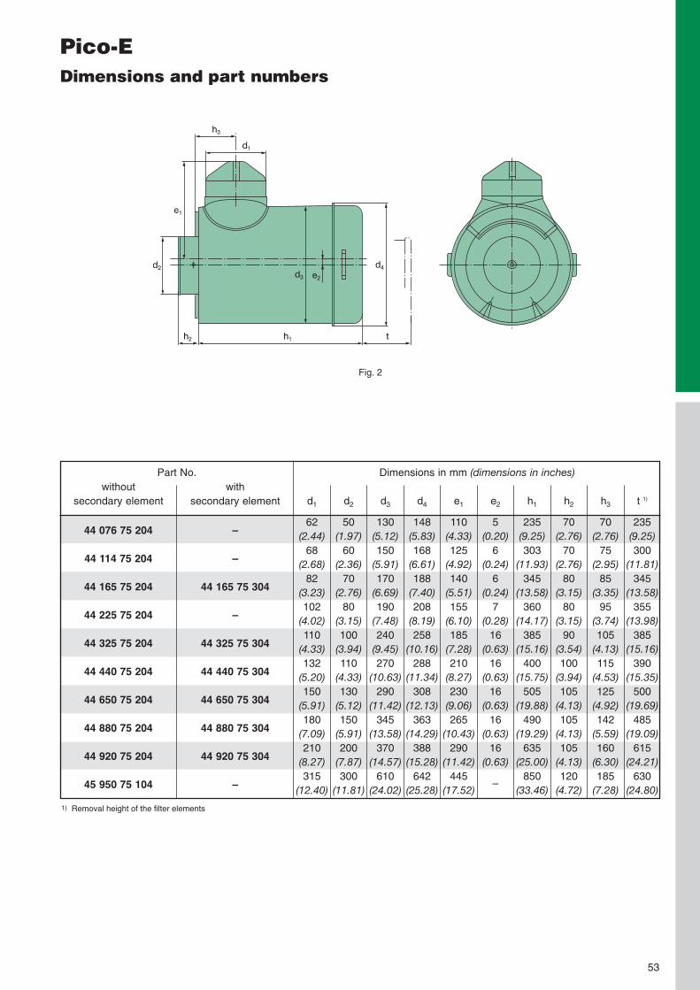
MANN+HUMMEL Pico-EHigh performance single-stage air cleanerwith very robust metal housing
49

marine applications and otherapplications where a lowpressure drop, particularlyhigh mechanical stability, ora flame-resistant housing arerequired.
The Pico-E line fromMANN+HUMMEL, with itsproven single-stage aircleaners, has long beenestablished in our rangeof air cleaners.
The air cleaners are particu-larly robust and are charac-terised by excellent filtrationperformance. They are verysuitable for use in conditionswith low to medium dust loadsand for applications with highmechanical loads such aswith stationary engines, loco-motives, fire-fighting vehicles,
50
Sectional view
Advantages at a glance:
• very robust metal design• long filter service life withlow pressure drop
• especially robust filter ele-ments with centre tubes inmetal
• secondary element avail-able as optional extra
Pico-E: Single-stage air cleaner with metal housing
eccentric arrangementof filter element
secondary element optional(not shown here)
filter element

51
Filter elements
Filter element
• high dust capacity throughspecial MANN+HUMMELfilter medium
• reliable pleat stabilisationprevents pleats stickingtogether under unfavour-able conditions
• an axial tie-rod firmly weld-ed into the housing anda fastening nut hold theelement securely in thesealed position.
Secondary element
• MANN+HUMMEL syntheticfabric for a high safetymargin with low pressuredrop
• secure fit in housing throughtie-rod and fastening nutprevent unintentional remov-al of the secondary element
• secondary element availa-ble as option from aircleaner size 44 114 …
The exceptionally low pres-sure drop of the Pico-E ismade possible through theenlarged dirty air connectionand eccentric arrangementof the filter element in thehousing.

d1
d2 d4
d3 e2
h2 h1 t
h3
e1
Connection for service indi-cation equipment (M10 x 1)
The nominal flow rate relates to a flow resistance [∆p] ] of approx. 15 mbar (1.5 kPa), for air cleaners with secondary element up to approx. 22 mbar (2.2 kPa).Weight valid for versions with last digits ... 204.
Pico-EDimensions and part numbers
1)
2)
withoutsecondary element
44 076 75 20444 114 75 20444 165 75 20444 225 75 20444 325 75 20444 440 75 20444 650 75 20444 880 75 20444 920 75 20445 950 75 104
withsecondary element
––
44 165 75 304–
44 325 75 30444 440 75 30444 650 75 30444 880 75 30444 920 75 304
–
Part No. Nominalflow rate 1)
[m3/min]
34.568121521284060
Replacement filter elementMANN-FILTERmain element
C 1176/3C 13 114/4C 15 165/3C 17 225/3C 20 325/2C 23 440/1C 24 650/1C 30 850/2C 33 920/3C 45 4444
MANN-FILTERsecondary element
––
CF 700–
CF 1000CF 1200CF 1300CF 1600CF 2100
–
Approx.weight 2)
[kg]
1.82.63.94.76.88.512152057
Fig.
1111111112
33.5(1.32)
Fig. 1
52
Pico-EDimensions and part numbers
d1
d2 d4d3
h2 h1 t
h3
e2
e1
withoutsecondary element
44 076 75 204
44 114 75 204
44 165 75 204
44 225 75 204
44 325 75 204
44 440 75 204
44 650 75 204
44 880 75 204
44 920 75 204
45 950 75 104
withsecondary element
–
–
44 165 75 304
–
44 325 75 304
44 440 75 304
44 650 75 304
44 880 75 304
44 920 75 304
–
Part No. Dimensions in mm (dimensions in inches)
d1
62(2.44)68
(2.68)82
(3.23)102
(4.02)110
(4.33)132
(5.20)150
(5.91)180
(7.09)210
(8.27)315
(12.40)
d2
50(1.97)60
(2.36)70
(2.76)80
(3.15)100
(3.94)110
(4.33)130
(5.12)150
(5.91)200
(7.87)300
(11.81)
d3
130(5.12)150
(5.91)170
(6.69)190
(7.48)240
(9.45)270
(10.63)290
(11.42)345
(13.58)370
(14.57)610
(24.02)
d4
148(5.83)168
(6.61)188
(7.40)208
(8.19)258
(10.16)288
(11.34)308
(12.13)363
(14.29)388
(15.28)642
(25.28)
e1
110(4.33)125
(4.92)140
(5.51)155
(6.10)185
(7.28)210
(8.27)230
(9.06)265
(10.43)290
(11.42)445
(17.52)
e2
5(0.20)6
(0.24)6
(0.24)7
(0.28)16
(0.63)16
(0.63)16
(0.63)16
(0.63)16
(0.63)
–
h1
235(9.25)303
(11.93)345
(13.58)360
(14.17)385
(15.16)400
(15.75)505
(19.88)490
(19.29)635
(25.00)850
(33.46)
h2
70(2.76)70
(2.76)80
(3.15)80
(3.15)90
(3.54)100
(3.94)105
(4.13)105
(4.13)105
(4.13)120
(4.72)
h3
70(2.76)75
(2.95)85
(3.35)95
(3.74)105
(4.13)115
(4.53)125
(4.92)142
(5.59)160
(6.30)185
(7.28)
t 1)
235(9.25)300
(11.81)345
(13.58)355
(13.98)385
(15.16)390
(15.35)500
(19.69)485
(19.09)615
(24.21)630
(24.80)
Removal height of the filter elements1)
Fig. 2
53

4407
6 ...44
114 .
..44
165 .
..44
225 .
..44
325 .
..44
440 .
..44
650 .
..44
880 .
..44
920 .
..45
950 75
104
... for flow rates as per ISO 5011
... for dust capacity as per ISO 5011with SAE coarse test dust
Flow
resis
tanc
e[m
bar]
Volume flow V̇ [m3/min]
54Versions for volume flows below 4.5 m3/min available on request.
Flow
resis
tanc
e[m
bar]
Dust capacity [g]0 50 100 150 200 250 300 350 400
80706050403020100
Flow
resis
tanc
e[m
bar]
Dust capacity [g]0 100 200 300 400 500 600 700 800
80706050403020100
Flow
resis
tanc
e[m
bar]
Dust capacity [g]0 200 400 600 800 1000 1200 1400
80706050403020100
Flow
resis
tanc
e[m
bar]
Dust capacity [g]0 200 400 600 800 1000 1200 1400 1600
80706050403020100
Flow
resis
tanc
e[m
bar]
Dust capacity [g]0 500 1000 1500 2000 2500 3000 3500
80706050403020100
Flow
resis
tanc
e[m
bar]
Dust capacity [g]0 1000 2000 3000 4000 5000 6000
80706050403020100
Flow
resis
tanc
e[m
bar]
Dust capacity [g]0 1000 2000 3000 4000 5000 6000 7000
80706050403020100
Flow
resis
tanc
e[m
bar]
Dust capacity [g]0 1000 2000 3000 4000 5000 6000 7000 8000 9000 10000
80706050403020100
Flow
resis
tanc
e[m
bar]
Dust capacity [g]0 1000 2000 3000 4000 5000 6000 7000 8000 9000 10000
80706050403020100
Pico-EFlow characteristics without secondary element ...
1 2 3 4 5 6 7 8 10 1520 30 4050 100
5040
30
2015
10
54
3
2
1
Flow
resis
tanc
e[m
bar]
Dust capacity [g]0 500 1000 1500 2000 2500
80706050403020100
44 076 ... – 3 m3/min.
44 114 ... – 4.5 m3/min.
44 165 ... – 6 m3/min.
44 225 ... – 8 m3/min.
44 325 ... – 12 m3/min.
44 440 ... – 15 m3/min.
44 650 ... – 21 m3/min.
44 880 ... – 28 m3/min.
44 920 ... – 40 m3/min.
45 950 75 104 – 60 m3/min.

4432
5 ...
4444
0 ...
4465
0 ...
4488
0 ...
4492
0 ...
4416
5 ...
... for flow rates as per ISO 5011
... for dust capacity as per ISO 5011with SAE coarse test dust
Flow
resis
tanc
e[m
bar]
Volume flow V̇ [m3/min]
55
Pico-EFlow characteristics with secondary element ...
1 2 3 4 5 6 78 10 15 20 30 40 50 100
5040
30
2015
10
54
3
2
1
Flow
resis
tanc
e[m
bar] 80
706050403020100
Flow
resis
tanc
e[m
bar]
Dust capacity [g]0 500 1000 1500 2000 2500
80706050403020100
Flow
resis
tanc
e[m
bar]
Dust capacity [g]0 500 1000 1500 2000 2500 3000 3500
80706050403020100
Flow
resis
tanc
e[m
bar]
Dust capacity [g]0 500 1000 1500 2000 2500 3000 3500 4000 4500 5000
80706050403020100
Flow
resis
tanc
e[m
bar]
Dust capacity [g]0 1000 2000 3000 4000 5000 6000
80706050403020100
Flow
resis
tanc
e[m
bar] 80
706050403020100
Dust capacity [g]0 200 400 600 800 1000 1200 1400
Dust capacity [g]0 1000 2000 3000 4000 5000 6000 7000 8000 9000
44 440 ... – 15 m3/min.
44 165 ... – 6 m3/min.
44 325 ... – 12 m3/min.
44 650 ... – 21 m3/min.
44 880 ... – 28 m3/min.
44 920 ... – 40 m3/min.

56
Pico-E Accessories
Pico-E 44 076 ...Pico-E 44 114 ...Pico-E 44 165 ...Pico-E 44 225 ...Pico-E 44 325 ...Pico-E 44 440 ...Pico-E 44 650 ...Pico-E 44 880 ...Pico-E 44 920 ...Pico-E 45 950 ...
Bracket Rain cap Straight pipes 90° elbow
(p. 97)
45 076 38 98045 114 38 99045 165 38 98045 225 38 99039 056 38 98045 440 38 99039 440 38 99039 880 38 94045 880 38 99045 940 38 841
design B *
(p. 99)
39 028 67 90039 040 67 90039 056 67 90039 080 67 90039 100 67 02039 160 67 02045 880 67 10039 220 67 10039 320 67 10039 640 67 100
connection for service indicator/service
switch integrated in housing (p. 105)
39 100 27 99939 200 27 99939 300 27 99939 400 27 99939 500 27 99939 600 27 99939 700 27 99939 800 27 99939 000 27 345
–
connection for service indicator/service
switch integrated in housing (p. 104)
39 100 25 99939 200 25 99939 300 25 99939 400 25 99939 500 25 99939 600 25 99939 700 25 99939 800 25 99939 000 25 270
–
You will find the completerange of accessories for ourair cleaners and service indi-cators/switches on page 93.
* Alternative design A possible(see page 98)

MANN+HUMMEL Oil-bath air cleanerSingle-stage air cleaner without spare parts
57

Servicing can be made with-out spare parts using engineoil available on site and clean-ing can be carried out withDiesel fuel. This makes theoil-bath cleaner practicallyindependent of service
The proven oil-bath aircleaners fromMANN+HUMMEL aresuitable for light to mediumdust conditions and havelong been established inour range of air cleaners.
58
supplies. It is therefore oftenused in machines and ve-hicles which have to operatereliably in remote regionswhere a supply of spareparts is not always guaran-teed.
dirty air inlet
Sectional view
Advantages at a glance:
• very robust metal design• servicing without spareparts
• volumetric flow ratesbetween 1.4 m3/min and19 m3/min are covered
• different versions; availablewith integrated mountingflange
Oil-bath air cleaner: Servicing without spare parts
clean air outlet
filter insert
oil reservoir
Design and principle ofoperation
Intake air is routed via the oilbath. There the coarse par-ticles are removed from theair and the air is reroutedupwards. As the air streamsupwards, oil from the oil bathwets the filter packing andthe dirt in the intake air isdeposited there. The oil flowsback to the bath where thedirt settles.
The oil bath achieves a maxi-mum separation efficiency ofapprox. 98.5% and is there-fore not as efficient as thefiltration performance of amodern dry air cleaner(> 99.95%).

59
Servicing
A correctly dimensioned oil-bath cleaner will not lose oilwhen in operation. The ser-vicing of the oil-bath cleanershould be carried out at thelatest when the deposited dirthas reached half the heightof the oil level or if the oil hasbecome thick. To service theair cleaner the oil reservoir isfirst removed and the oil isdisposed of according to the
environmental regulations.Then the sludge is removedfrom the oil reservoir and themetal filter insert is taken out.This is cleaned with Diesel orwith a pressure washer. Thenthe oil reservoir is re-filledwith fresh standard engine oilup to the marking and placedin the housing together withthe insert.
When configuring the size,care should be taken that thenominal flow rate of the aircleaner is as close as possi-ble to, but not more than, themaximum air requirement ofthe engine. If an oil-bathair cleaner is specified to betoo large, or if the oil level istoo low, then the separationefficiency decreases.
If the oil-bath air cleaner isspecified to be too small, orif the oil level is too high, thenoil containing dirt may bedrawn through to the cleanside, resulting in prematureengine wear. When oil-bathcleaners are used with com-pressors and engines with1 – 4 cylinders (not turbo-charged), dimensions mustbe corrected using pulsationfactors to compensate for thepulsations in the air stream.
Oil-bath air cleaners must beinstalled vertically.
Dimensioning and installation

60
Oil-bath air cleanerDimensions and part numbers
Fig. 2Plain air intake connection; mounting viaflange on intake pipe
d2
d1
al
d3
d4
h2
h1
b
Fig. 1Plain air intake connection and clean air connection;Mounting through separate bracket
31 020 75 023
31 024 75 023
31 028 75 023
31 034 75 023
31 040 75 023
31 045 75 023
31 056 75 023
31 068 75 023
31 080 75 043
31 100 75 043
31 120 75 043
31 160 75 043
31 190 75 043
Part No. Nominalflow rate[m3/min]
2.0
2.4
2.8
3.4
4.0
4.5
5.6
6.8
8.0
10.0
12.0
16.0
19.0
Dimensions in mm (dimensions in inches)
a
110(4.33)110
(4.33)125
(4.92)125
(4.92)140
(5.51)140
(5.51)160
(6.30)160
(6.30)185
(7.28)210
(8.27)210
(8.27)260
(10.24)260
(10.24)
b
25(0.98)25
(0.98)20
(0.79)20
(0.79)20
(0.79)20
(0.79)25
(0.98)25
(0.98)20
(0.79)35
(1.48)35
(1.48)45
(1.77)45
(1.77)
d1
54(2.13)54
(2.13)62
(2.44)62
(2.44)68
(2.68)68
(2.68)82
(3.23)82
(3.23)102
(4.02)110
(4.33)110
(4.33)132
(5.20)132
(5.20)
d2
54(2.13)54
(2.13)62
(2.44)62
(2.44)70
(2.76)70
(2.76)82
(3.23)82
(3.23)102
(4.02)110
(4.33)110
(4.33)132
(5.20)132
(5.20)
d3
140(5.51)140
(5.51)173
(6.81)173
(6.81)200
(7.87)200
(7.87)240
(9.45)240
(9.45)280
(11.02)320
(12.60)320
(12.60)400
(15.75)400
(15.75)
d4
158(6.22)158
(6.22)190
(7.48)190
(7.48)220
(8.66)220
(8.66)260
(10.24)260
(10.24)300
(11.81)344
(13.54)344
(13.54)422
(16.61)422
(16.61)
h1
253(9.96)283
(11.14)267
(10.51)302
(11.89)297
(11.69)327
(12.87)322
(12.68)362
(14.25)367
(14.45)395
(15.55)425
(16.73)445
(17.52)495
(19.49)
h2
222(8.74)252
(9.92)232
(9.13)266
(10.47)255
(10.04)285
(11.22)276
(10.87)316
(12.44)304
(11.97)325
(12.80)355
(13.98)365
(14.37)410
(16.14)
l
55(2.17)55
(2.17)60
(2.36)60
(2.36)75
(2.95)75
(2.95)85
(3.35)85
(3.35)135
(5.32)140
(5.51)110
(4.33)165
(6.50)120
(4.72)
Oil[ltr.]
0.50
0.50
0.75
0.75
1.00
1.00
1.70
1.70
2.50
3.00
3.00
5.50
5.50
Fig.
1
1
1
1
1
1
1
1
1
1
1
1
1
Filter[kg]
2.1
2.3
3.0
3.3
3.7
4.3
5.6
6.4
7.8
10.7
11.2
18.0
20.0
d1
d3
d5
d2
d4h2
h1
a
b
l
f
i
g
Weight
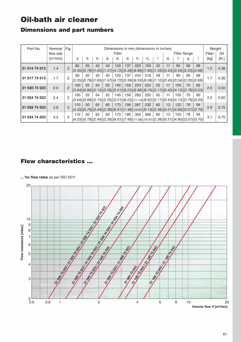
... for flow rates as per ISO 5011
Flow
resis
tanc
e[m
bar]
Volume flow V̇ [m3/min]0.6 0.8 1 2 4 6 8 10 20
61
Flow characteristics ...
20
10
9
8
7
6
5
4
3
2
31 014 74 013
31 017 74 013
31 020 74 023
31 024 74 023
31 028 74 023
31 034 74 023
Part No. Nominalflow rate[m3/min]
1.4
1.7
2.0
2.4
2.8
3.4
Dimensions in mm (dimensions in inches)
a
85(3.35)85
(3.35)100
(3.94)100
(3.94)110
(4.33)110
(4.33)
b
20(0.79)20
(0.79)25
(0.98)25
(0.98)20
(0.79)20
(0.79)
d1
42(1.65)42
(1.65)54
(2.13)54
(2.13)62
(2.44)62
(2.44)
d2
40(1.57)40
(1.57)52
(2.05)52
(2.05)60
(2.36)60
(2.36)
d3
120(4.72)120
(4.72)140
(5.51)140
(5.51)173
(6.81)173
(6.81)
d4
137(5.39)137
(5.39)158
(6.22)158
(6.22)190
(7.48)190
(7.48)
h1
220(8.66)242
(9.53)253
(9.96)283
(11.14)
267(10.87)
302(11.89)
h2
193(7.60)218
(8.58)222
(8.74)252
(9.92)232
(9.13)266
(10.47)
l
32(1.26)28
(1.10)55
(2.17)55
(2.17)60
(2.36)60
(2.36)
d5
11(0.43)11
(0.43)11
(0.43)11
(0.43)13
(0.51)13
(0.51)
f
90(3.54)90
(3.54)105
(4.13)105
(4.13)122
(4.80)122
(4.80)
g
56(2.20)56
(2.20)70
(2.76)70
(2.76)78
(3.07)78
(3.07)
i
68(2.68)68
(2.68)82
(3.23)82
(3.23)94
(3.70)94
(3.70)
Oil[ltr.]
0.36
0.36
0.50
0.50
0.75
0.75
Fig.
2
2
2
2
2
2
Filter[kg]
1.5
1.7
2.0
2.2
2.8
3.1
Filter Filter flange
Oil-bath air cleanerDimensions and part numbers
Weight

62
Accessories for oil-bath air cleaners
Oil-bath air cleaner 31 014 ...Oil-bath air cleaner 31 017 ...Oil-bath air cleaner 31 020 ...Oil-bath air cleaner 31 024 ...Oil-bath air cleaner 31 020 ...Oil-bath air cleaner 31 024 ...Oil-bath air cleaner 31 028 ...Oil-bath air cleaner 31 034 ...Oil-bath air cleaner 31 028 ...Oil-bath air cleaner 31 034 ...Oil-bath air cleaner 31 040 ...Oil-bath air cleaner 31 045 ...Oil-bath air cleaner 31 056 ...Oil-bath air cleaner 31 068 ...Oil-bath air cleaner 31 080 ...Oil-bath air cleaner 31 100 ...Oil-bath air cleaner 31 120 ...Oil-bath air cleaner 31 160 ...Oil-bath air cleaner 31 190 ...
Bracket(p. 97)
integrated (flange)
integrated (flange)
39 020 38 981
integrated (flange)
39 028 38 981
39 040 38 981
39 056 38 98139 080 38 99139 100 38 991
39 160 38 991
Rain cap design B *(p. 99)
39 014 67 900
39 020 67 900
39 020 67 900
39 028 67 900
39 028 67 900
39 040 67 900
39 056 67 90039 080 67 90039 100 67 020
39 160 67 020
You will find the completerange of accessories for ourair cleaners and service indi-cators/switches on page 93.
* Alternative design A possible(see page 98)

MANN+HUMMEL Inline PiclonTwo-stage plastic air cleaner with inline air flow
63

Advantages at a glance:
• linear air flow• compact design• economical air cleanersystem with integratedbracket
• easy element changewithout tools
• corrosion-free and robusthousing through use ofrecyclable plastic
• threaded inserts integratedin housing enable quickfirst-fit on vehicle
This two-stage air cleanerfrom MANN+HUMMEL withintegrated pre-separationis available in three sizes.The Inline Piclon is particu-larly suited for use in medi-um dust conditions and foruse with engines and com-pressors with pulsatingintake air.
64
Sectional view
Inline Piclon: Two-stage air cleaner with plastichousing
Filter configuration andinstallation
The Inline Piclon consistsof a plastic housing which isclosed on the outside by twowire clamps. Four screwslocated on the bottom allowthe air cleaner to be mountedin a vertical, hanging or hori-zontal position. If the air clean-er is mounted in a verticalposition, a secondary ele-ment must be installed. Dustdischarge is made via avalve. A separate bracket isnot necessary.
dust discharge valve
clean airoutlet
dirty airinlet
filter element secondary element optional(not shown here)
integratedbracket

65
Filter elements
Filter element
• high dust capacity throughspecial MANN+HUMMELfilter medium
• reliable pleat stabilisationprevents pleats stickingtogether in unfavourableconditions
• two closing clamps on theoutside of the housing en-sure that the filter elementis securely fitted in thehousing
Secondary element
• MANN+HUMMEL syntheticfabric for a high safetymargin with low pressuredrop
• secure fitting in the housingthrough a tie-rod and afastening nut prevent anunintentional removal ofthe secondary element
Dimensions and part numbers
M 8
M 10x1
connection forservice indicator/service switch
withoutsecondary element
45 160 92 90145 201 92 90445 250 92 905
withsecondary element
45 160 92 95145 201 92 95145 250 92 906
Part No. Nominalflow rate[m3/min]
5.36.06.7
Replacement filter elementMANN-FILTERmain element
C 17 160C 17 201C 17 250
MANN-Filtersecondary element
CF 820CF 820CF 830
Approx.weight[kg]
2.52.73.4
242 (for model 45 160 ...)(9.53)278 (for model 45 201 ...)(10.94)396 (for model 45 250 ...)(15.59)
dust discharge valve39 000 40 391
25(0.98)
41(1.61)
17(0.67)
ø 70(2.76)
ø 202(7.95)
35
(1.38)
ø 70(2.76)
ø 225(8.86)
119(4.69)
190(7.48)
ø 145(5.71)
17.5°

66
4516
0...
4520
1...
4525
0...
4516
0...
4520
1...
4525
0...
... with secondary element ...
... for flow rates as per ISO 5011
... for dust capacity with secondary elementas per ISO 5011 with SAE coarse test dust
Flow
resis
tanc
e[m
bar]
Flow
resis
tanc
e[m
bar]
Volume flow V̇ [m3/min]
Dust capacity [g]
Flow
resis
tanc
e[m
bar]
Dust capacity [g]
Flow
resis
tanc
e[m
bar]
Dust capacity [g]
Flow
resis
tanc
e[m
bar]
Dust capacity [g]
Flow
resis
tanc
e[m
bar]
Flow
resis
tanc
e[m
bar]
Dust capacity [g] Dust capacity [g]
Inline Piclon 160 – 5.3 m3/min.
Inline Piclon 201 – 6.0 m3/min.
Inline Piclon 250 – 6.7 m3/min. Inline Piclon 250 – 6.7 m3/min.
Inline Piclon 201 – 6.0 m3/min.
Inline Piclon 160 – 5.3 m3/min.
Inline PiclonFlow characteristics ...
0 1 2 3 4 5 6 7 8 9 10
... for dust capacity without secondary elementas per ISO 5011 with SAE coarse test dust
... without secondary element ...
... for flow rates as per ISO 501150
40
30
20
10
0
Flow
resis
tanc
e[m
bar]
Volume flow V̇ [m3/min]0 1 2 3 4 5 6 7 8 9 10
50
40
30
20
10
0
0 500 1000 1500 2000 2500
80706050403020100
0 500 1000 1500 2000 2500 3000
80706050403020100
0 500 1000 1500 2000 2500 3000 3500
80706050403020100
0 500 1000 1500 2000 2500 3000 3500 4000
80706050403020100
80706050403020100
80706050403020100
0 500 1000 1500 2000 2500 3000 3500 4000 4500 5000 0 1000 2000 3000 4000 5000 6000

MANN+HUMMEL PicolinoCompact air cleaner system for high requirements
67

The Picolino line fromMANN+HUMMEL offersexceptional filtration in acompact installation spacewith excellent flexibility.The Picolino line is avail-able with a number ofdifferent connections toenable it to adapt to differ-ent applications.
68
Advantages at a glance:
• excellent flexibility throughvariable modular system
• economical air cleanersystem through combinationof standard parts
• easy element changewithout tools
• corrosion-free and robusthousing through use ofplastic reinforced with fibre-glass
• temperature resistant to+130 °C (for short periods)
Picolino modular system
• material with high tempera-ture stability available foradapters on request
• quick response to custom-ised filtration solutions
• metal-free filter elementsare easily disposed of byincineration and thereforeare environmentally friendlywith inexpensive disposal
• patented filter elementswith radial seal
Picolino: Compact air cleaner for high requirements
The product line consists offive master housings withvarious adapter pieces whichcan be used to adapt thecleaner to the individualrequirements of customisedapplications. The housing,adapters and filter elementsare free of metal. Dependingon the design, the systemcovers nominal flow ratesfrom 0.15 m3/min to3.2 m3/min.
cover
filter element
housing
dirty air adapter ...
... for silencer air cleanersclean air adapter
adapter withinternal thread
adapter withexternal thread
push-onadapter

69
Filter elements
• high dust capacity throughspecial MANN+HUMMELfilter medium
• radial seal through elasto-mer end plates (protectedby patents)
• reliable pleat stabilisationprevents pleats stickingtogether under unfavour-able conditions
The right configuration forevery application
The air cleaners of thePicolino line are availablewith a number of connectionfittings and are, for example,suitable for:
• silencer air cleaners forlow-noise air intake, e.g. insmall piston compressors
• intake air cleaners for smallengines (lawn mowers,power generators, etc.)
• two-way ventilation aircleaners for gear unitsand tanks for liquids
Applications

70
Picolino Intake air cleaners (two-way ventilation aircleaners)Dimensions and part numbers
t
h1
h2
e1
d1 l
ød 2
h1
t
h2
e1
d1 l
ød 2
Fig. 1 Fig. 2
Cover Cover

71
Picolino Intake air cleaners (two-way ventilation aircleaners)Dimensions and part numbers
The nominal flow rate relates to a flow resistance of 15 mbar. The flow rate depends on the cross-section of the clean air outlet.External threadInternal thread
1)
2)
3)
Part No.
44 010 72 996
44 010 72 997
44 010 72 999
44 010 77 999
44 020 72 996
44 020 72 997
44 020 72 999
44 020 77 999
44 030 72 999
44 030 77 997
44 030 77 998
44 030 77 999
44 040 72 999
44 040 77 996
44 040 77 997
44 040 77 998
44 040 77 999
44 050 72 999
44 050 77 996
44 050 77 997
44 050 77 998
44 050 77 999
Nominalflow rate[m3/min] 1)
0.3
0.2
0.2
0.3
0.3
0.3
0.2
0.3
0.8
1.2
1.2
0.7
2.1
3.0
2.8
2.6
2.1
2.3
3.5
3.4
3.1
2.3
MANN-FILTERmain element
C 410
C 410
C 410
C 410
C 420
C 420
C 420
C 420
C 630
C 630
C 630
C 630
C 1140
C 1140
C 1140
C 1140
C 1140
C 1250
C 1250
C 1250
C 1250
C 1250
Fig.
2
2
2
1
2
2
2
1
2
1
1
1
2
1
1
1
1
2
1
1
1
1
t
30(1.18)30
(1.18)30
(1.18)30
(1.18)30
(1.18)30
(1.18)30
(1.18)30
(1.18)68
(2.68)68
(2.68)68
(2.68)68
(2.68)79
(3.11)79
(3.11)79
(3.11)79
(3.11)79
(3.11)135
(5.32)135
(5.32)135
(5.32)135
(5.32)135
(5.32)
d1
G 1/2 3)
G 3/8 3)
M 18x1.5 2)
35(1.38)
G 1/2 3)
G 3/8 3)
M 18x1.5 2)
35(1.38)
G 3/4 3)
40(1.57)30
(1.18)20
(0.79)
G 11/4 3)
71(3.00)60
(2.36)52
(2.05)40
(1.57)
G 11/4 3)
71(3.00)60
(2.36)52
(2.05)40
(1.57)
l
27(1.06)27
(1.06)27
(1.06)27
(1.06)31
(1.22)31
(1.22)31
(1.22)31
(1.22)48
(1.89)48
(1.89)48
(1.89)48
(1.89)69
(2.72)69
(2.72)69
(2.72)69
(2.72)69
(2.72)86
(3.39)86
(3.39)86
(3.39)86
(3.39)86
(3.39)
Dimensions in mm (dimensions in inches)
d2
58(2.28)58
(2.28)58
(2.28)58
(2.28)68
(2.68)68
(2.68)68
(2.68)68
(2.68)102
(4.02)102
(4.02)102
(4.02)102
(4.02)145
(5.71)145
(5.71)145
(5.71)145
(5.71)145
(5.71)181
(7.13)181
(7.13)181
(7.13)181
(7.13)181
(7.13)
e1
14(0.55)11
(0.43)10
(0.39)23
(0.91)14
(0.55)11
(0.43)10
(0.39)23
(0.91)15
(0.59)25
(0.98)23
(0.91)23
(0.91)19
(0.75)25
(0.98)25
(0.98)25
(0.98)25
(0.98)19
(0.75)25
(0.98)25
(0.98)25
(0.98)25
(0.98)
h1
61(2.40)61
(2.40)61
(2.40)73
(2.87)62
(2.44)62
(2.44)62
(2.44)74
(2.91)94
(3.70)116
(4.57)116
(4.57)116
(4.57)131
(5.16)136
(5.35)136
(5.35)136
(5.35)136
(5.35)188
(7.40)193
(7.60)193
(7.60)193
(7.60)193
(7.60)
h2
34(1.34)34
(1.34)34
(1.34)64
(2.52)34
(1.34)34
(1.34)34
(1.34)46
(1.81)45
(1.77)67
(2.64)67
(2.64)67
(2.64)71
(2.80)76
(2.99)76
(2.99)76
(2.99)76
(2.99)112
(4.41)117
(4.61)117
(4.61)117
(4.61)117
(4.61)

72
Picolino Silencer air cleanersDimensions and part numbers
h1
h2
e1
d1 l
t
ød 2
h1
h2
e1
d1 l
t
ød 2
Fig. 1 Fig. 2
cover cover

73
Picolino Silencer air cleanersDimensions and part numbers
Part No.
44 010 82 996
44 010 82 997
44 010 82 999
44 010 87 999
44 020 82 996
44 020 82 997
44 020 82 999
44 020 87 999
44 030 82 999
44 030 87 997
44 030 87 998
44 030 87 999
44 040 82 999
44 040 87 996
44 040 87 997
44 040 87 998
44 040 87 999
44 050 82 999
44 050 87 996
44 050 87 997
44 050 87 998
44 050 87 999
Nominalflow rate[m3/min] 1)
0.2
0.1
0.1
0.2
0.2
0.2
0.2
0.2
0.6
0.8
0.8
0.5
1.7
2.0
2.0
1.9
1.6
2.0
2.8
2.8
2.5
2.0
MANN-FILTERmain element
C 410
C 410
C 410
C 410
C 420
C 420
C 420
C 420
C 630
C 630
C 630
C 630
C 1140
C 1140
C 1140
C 1140
C 1140
C 1250
C 1250
C 1250
C 1250
C 1250
Fig.
2
2
2
1
2
2
2
1
2
1
1
1
2
1
1
1
1
2
1
1
1
1
t
30(1.18)30
(1.18)30
(1.18)30
(1.18)30
(1.18)30
(1.18)30
(1.18)30
(1.18)68
(2.68)68
(2.68)68
(2.68)68
(2.68)79
(3.11)79
(3.11)79
(3.11)79
(3.11)79
(3.11)135
(5.32)135
(5.32)135
(5.32)135
(5.32)135
(5.32)
d1
G 1/2 3)
G 3/8 3)
M 18x1.5 2)
35(1.38)
G 1/2 3)
G 3/8 3)
M 18x1.5 2)
35(1.38)
G 3/4 3)
40(1.57)30
(1.18)20
(0.79)
G 11/4 3)
71(2.80)60
(2.36)52
(2.05)40
(1.57)
G 11/4 3)
71(2.80)60
(2.36)52
(2.05)40
(1.57)
l
56(2.20)56
(2.20)56
(2.20)56
(2.20)60
(2.36)60
(2.36)60
(2.36)60
(2.36)95
(3.74)95
(3.74)95
(3.74)95
(3.74)79
(3.11)79
(3.11)116
(4.57)116
(4.57)116
(4.57)133
(5.24)133
(5.24)133
(5.24)133
(5.24)133
(5.24)
Dimensions in mm (dimensions in inches)
d2
58(2.28)58
(2.28)58
(2.28)58
(2.28)68
(2.68)68
(2.68)68
(2.68)68
(2.68)102
(4.02)102
(4.02)102
(4.02)102
(4.02)145
(5.71)145
(5.71)145
(5.71)145
(5.71)145
(5.71)181
(7.13)181
(7.13)181
(7.13)181
(7.13)181
(7.13)
e1
14(0.55)11
(0.43)10
(0.39)23
(0.91)14
(0.55)11
(0.43)10
(0.39)23
(0.91)15
(0.59)25
(0.98)23
(0.91)23
(0.91)19
(0.75)25
(0.98)25
(0.98)25
(0.98)25
(0.98)19
(0.75)25
(0.98)25
(0.98)25
(0.98)25
(0.98)
h1
61(2.40)61
(2.40)61
(2.40)73
(2.87)62
(2.44)62
(2.44)62
(2.44)74
(2.91)94
(3.70)116
(4.57)116
(4.57)116
(4.57)131
(5.16)136
(5.35)136
(5.35)136
(5.35)136
(5.35)188
(7.40)193
(7.60)193
(7.60)193
(7.60)193
(7.60)
h2
34(1.34)34
(1.34)34
(1.34)46
(1.81)34
(1.34)34
(1.34)34
(1.34)46
(1.81)45
(1.77)67
(2.64)67
(2.64)67
(2.64)71
(2.80)76
(2.99)76
(2.99)76
(2.99)76
(2.99)112
(4.41)117
(4.61)117
(4.61)117
(4.61)117
(4.61)
e2
29(1.14)29
(1.14)29
(1.14)29
(1.14)29
(1.14)29
(1.14)29
(1.14)29
(1.14)47
(1.85)47
(1.85)47
(1.85)47
(1.85)55
(2.17)55
(2.17)53
(2.09)53
(2.09)53
(2.09)55
(2.17)55
(2.17)59
(2.32)59
(2.32)59
(2.32)
The nominal flow rate relates to flow resistance of 15 mbar. The flow rate depends on the cross-section of the clean air outlet.External threadInternal thread
1)
2)
3)

74

MANN+HUMMEL PicolightSingle-stage air cleaner without housing
75

Advantages at a glance:
• low pressure drop• very economical• compact design• metal-free design• excellent filtration perfor-
mance
The metal-free air cleanersof the Picolight line fromMANN+HUMMEL are char-acterised by an especiallylow-weight and compactdesign. We particularlyrecommend these air clean-ers for use in stationaryapplications with low dustloads such as generators,compressors, marine en-gines, etc.
76
Picolight: Single stage air cleaner without housing
Technical information
Use of MANN+HUMMELstandard high quality filtermedia achieves high separa-tion efficiency and filtrationperformance in the Picolight.The Picolight is recommend-ed for use in installationareas which are enclosed orprotected against humidity.The types shown here covervolumetric flows from 1 m3/minto 100 m3/min. A tensioningstrap is required to mount theair cleaner.

77
PicolightDimensions and part numbers
4503
154
154
4517
454
154
4592
056
844
4510
054
134
4506
854
194
... for flow rates as per ISO 5011
Flow
resis
tanc
e[m
bar]
Volume flow V̇ [m3/min]0.1 1 10 100
10
1
0.1
unpacked
45 031 54 154
45 068 54 194
45 100 54 134
45 174 54 154
45 920 56 844
Part No.MANN-FILTER Picolight
Nominalflow rate1)
[m3/min]
3.3
6.8
7.7
12.5
80
Dimensions in mm (dimensions in inches)
d1
50(1.97)
76(2.99)
76(2.99)100
(3.94)250
(9.84)
d2
65(2.56)
90(3.54)
90(3.54)120
(4.72)260
(10.24)
d3
110(4.33)130
(5.12)160
(6.30)230
(9.06)425
(16.73)
h1
120(4.72)150
(5.91)165
(6.50)156
(6.14)404
(15.91)
h2
95(3.74)125
(4.92)140
(5.51)120
(4.72)335
(13.19)
Tighteningstrap
02 018 01 709
02 018 01 712
02 018 01 712
02 018 01 715
02 018 01 728
packed
C 1131
C 1368
C 17 100
C 23 174
C 43 1090/1
e
20(0.79)
20(0.79)
25(0.98)
30(1.18)
80(3.15)
Approx.weight
[kg]
0.16
0.24
0.38
0.68
5.60
Flow characteristics ...
The nominal flow rate relates to flow resistance of 10 mbar.1)
d3
d2
d1
h2
h1
e

78

MANN+HUMMEL Oil-wetted air cleanersSingle-stage air cleaners without housing
79

An oil-wetted air cleaner,however, with a maximumseparation efficiency ofapprox. 70% (ISO 5011)does not achieve the perfor-mance of a modern dry aircleaner (> 99.95%).
Advantages at a glance:
• parts do not require repla-cing
• compact design• robust metal design
80
Oil-wetted air cleaners
Technical information
The air drawn in through anoil-wetted air cleaner flowsthrough a packing wettedwith oil and made of expand-ed metal or knitted steelmesh. Dust particles aredeposited on the oil-wettedsurface of the filter packing.Position the air cleaner insuch a way that extracteddust cannot be shaken backonto the clean side. It maybe installed horizontally tovertically downwards. The aircleaner must be adequatelyshielded from rain and anywater spray. The tighteningstrap necessary for mountingis already integrated on theair cleaner so that no addi-tional parts are required forinstallation.
MANN+HUMMEL oil-wettedair cleaners are suitable forthe filtration of intake air inengines and machines op-erating in low-dust areas.
These include stationary en-gines, compressors in closedrooms and marine engines,etc. Oil-wetted air cleanerscontain parts which do notrequire replacement for thelife of the product. Regularservicing ensures that the fil-tration performance is main-tained for the life of product.
Servicing
When dust becomes clearlyvisible on the filter, wash itout with Diesel fuel. Afterwashing, shake off the excessfuel well. Oil-wetted air clean-ers may also be cleaned witha steam jet cleaner. Aftercleaning, apply an even, thinlayer of engine oil to the filterpacking (if dipped in an oilbath, shake off the excess oilafterwards). If servicing is ne-glected, separation perfor-mance will reduce significantly.

81
Oil-wetted air cleanersDimensions and part numbers
d1
d2
h2
h1
43 014 67 012
43 018 67 012
43 018 67 022
43 036 67 012
43 046 67 012
43 060 67 012
43 080 67 102
43 100 67 012
43 130 67 012
43 180 67 012
43 240 67 012
43 320 67 012
43 870 67 102
Part No. Nominalflow rate 1)
[m3/min]
1.4
1.8
1.8
3.6
4.6
6
8
10
13
18
24
32
87
Dimensions in mm (dimensions in inches)
d1
30(1.18)35
(1.38)40
(1.57)52
(2.05)60
(2.36)66
(2.60)70
(2.76)80
(3.15)100
(3.94)120
(4.72)150
(5.91)200
(7.87)300
(11.81)
d2
80(3.15)80
(3.15)80
(3.15)107
(4.21)107
(4.21)120
(4.72)120
(4.72)147
(5.79)147
(5.79)166
(6.54)196
(7.72)232
(9.13)340
(13.39)
h1
78(3.07)90
(3.54)90
(3.54)110
(4.33)128
(5.04)140
(5.51)175
(6.89)180
(7.09)215
(8.46)250
(9.84)285
(11.22)330
(12.99)640
(25.20)
h2
32(1.26)32
(1.26)32
(1.26)32
(1.26)34
(1.34)35
(1.38)35
(1.38)38
(1.38)38
(1.38)38
(1.38)50
(1.97)45
(1.77)95
(3.74)
Weightapprox.[kg]
0.25
0.4
0.3
0.6
0.8
1.0
1.2
1.5
1.8
2.5
3.3
5.4
16.0
Nominal flow rate relates to approx. 15 mbar.1)

82
Oil-wetted air cleanersFlow characteristics ...
4301
467
012
4310
067
012
4332
067
012
4387
067
102
4324
067
012
4313
067
012
4318
067
012
4308
067
102
4306
067
012
4304
667
012
4303
667
012
4301
867
022
4301
867
012
... for flow rates as per ISO 5011
Flow
resis
tanc
e[m
bar]
Volume flow V̇[m3/min]0.5 0.6 0.8 1 2 4 6 8 10 20 40 60 80 100
20
109
8
7
6
5
4
3
2
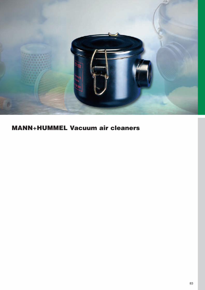
MANN+HUMMEL Vacuum air cleaners
83

Advantages at a glance:
• reliable sealing• compact design• robust metal design• different connections areavailable
• excellent filtration perfor-mance
84
Vacuum air cleaners
Technical information
The air cleaner size dependson its nominal flow rate. Theair cleaner size is to be se-lected so that the nominalflow rate of the air cleaner isequal or greater than the airrequirement.
The airtight vacuum aircleaners fromMANN+HUMMEL are de-signed for installation in airand gas pipes. They areairtight up to 1000 mbarnegative pressure andequipped with a filter ele-ment. They are also usedas intake filters in vacuumpumps.
The air cleaner can be install-ed vertically or horizontally,however it should not bemounted with the clean airoutlet at the bottom, as other-wise dirt can enter the cleanair pipe during a service.

85
Vacuum air cleanersDimensions and part numbers
d1
h2
h4
d1
d2
h1
d4
h3
d3
t
Fig. 1: Model with thread
Fig. 2: Model with small
flange as per DIN 28403-2
h2
d4
h3
d1
h1
t
45 009 72 105
45 021 72 10545 021 72 12545 021 72 305
45 037 72 10545 037 72 13545 037 72 305
45 124 72 10445 124 72 11445 124 72 305
45 138 72 105
Part No. Nominalflow rate[m3/min]
0.7
1.6
1.8
6.0
12.0
Dimensions in mm (dimensions in inches)
d1
G 3/4
G 1 1/41 1/4 NPTDN 40 KF
G 1 1/41 1/4 NPTDN 40 KF
G 2 1/22 1/2 NPTDN 50 KF
G 4
d2
35(1.38)
50(1.97)
50(1.97)
86(3.39)
123(4.84)
d3
90(3.54)
125(4.92)
162(6.38)
194(7.64)
268(10.55)
d4
97(3.82)
136(5.35)
172(6.77)
200(7.87)
272(10.71)
h1
89(3.50)
116(4.57)
170(6.69)
250(9.84)
263(10.35)
h2
45(1.77)68
(2.68)65
(2.56)108
(4.25)106
(4.17)129
(5.08)145
(5.71)147
(5.79)
h3
59(2.32)81
(3.19)106
(4.17)98
(3.86)123
(4.84)123
(4.84)140
(5.51)197
(7.76)
h4
6(0.24)
17(0.67)
17(0.67)
10(0.39)
74(2.91)
t
70(2.76)
75(2.95)
130(5.12)
240(9.45)
165(6.50)
Approx.weight[kg]
0.6
1.0
1.5
4.3
14.5
Fig.
1
112
112
112
1
MANN-FILTERmain element
C 75
C 1112
C 1337
C 15 124/1
C 21 138/1

86
Vacuum air cleanersFurther MANN+HUMMEL filters suitable for use with vacuums
There are other filter sys-tems available fromMANN+HUMMEL in additionto the vacuum air cleanerslisted here which are suitablefor use with applications withvacuums. These are speciallymodified plastic and metal fil-ters. The modified Europiclon®
line is shown on page 21.Further information is availablefrom your MANN+HUMMELpartner.
Vacuum air cleanersFlow characteristics ...
4500
972
...
4502
172
...
4512
472
...
4513
872
...
4503
772
...
... for flow rates as per ISO 5011
Flow
resis
tance[m
bar]
Volume flow V̇ [m3/min]0.2 0.3 0.5 1 2 3 4 5 10 20
50
40
30
20
10
5
1

MANN+HUMMEL Two-way ventilation aircleaners for crankcases, gear unit housingsand hydraulic tanks
MANN+HUMMEL Silencer air cleaners
87

Dry air cleaners offer a veryhigh filtration performance ofover 99.5%, but must be re-placed when they are full ofdirt. Oil-wetted air cleanersachieve a lower separationof only approx. 70%, but canbe cleaned and re-used.
There are models availablewith an integrated pressureregulating valve. There isalso the option of using themetal-free filters of thePicolino line (see page 67).
The two-way ventilationair cleaners fromMANN+HUMMEL are single-stage air cleaners whichare mainly used for the two-way ventilation of liquids intanks and gear units. Thecleaners are available asdry air cleaners and as oil-wetted cleaners.
88
Air cleaners for two-way ventilation
Two-way ventilation air cleaners (dry air cleaners)
Flow characteristics ...
4502
177
125
4537
577
104
4524
077
104
4513
877
126
4507
477
115
4503
777
015
4503
277
105
4500
972
146
4500
977
106
4500
362
902
4500
365
900
4500
162
185
Flow
resis
tanc
e[m
bar]
Volume flow V̇ [m3/min]0.06 0.080.1 0.2 0.4 0.6 0.8 1 1.2
30
20
1098
65
4
3
Flow
resis
tanc
e[m
bar]
Volume flow V̇ [m3/min]1 2 4 6 8 10 20 40 50
30
20
1098
65
4
3
... for flow rates as per ISO 5011

89
Two-way ventilation air cleaners (dry air cleaners)Dimensions and part numbers
h
d1
d2
h
d1
d2
h
d1
d2
1) The entire air cleaner is exchanged during a service.2) With integrated pressure regulating valve.
45 001 62 185
45 003 65 900
45 003 62 902
45 003 62 900 2)
45 003 62 901 2)
45 009 72 146
45 009 77 106
45 021 77 125
45 032 77 105
45 037 77 015
45 074 77 115
45 138 77 126
45 240 77 104
45 375 77 104
Part No. Dimensions in mm(dimensions in inches)
d1
M 18x1.5
35(1.38)
G 3/4
G 3/4
G 3/4
M 26x1.5
20(0.79)40
(1.57)52
(2.05)60
(2.36)80
(3.15)100
(3.94)140
(5.51)180
(7.09)
d2
45(1.77)80
(3.15)80
(3.15)80
(3.15)80
(3.15)98
(3.86)98
(3.86)132
(5.20)132
(5.20)170
(6.69)208
(8.19)283
(11.14)318
(12.52)396
(15.59)
h
47(1.85)65
(2.56)73.5(2.89)73.5(2.89)73.5(2.89)110
(4.33)110
(4.33)120
(4.72)152
(5.98)175
(6.89)185
(7.28)200
(7.87)302
(11.89)285
(11.22)
Approx.weight[kg]
0.08
0.06
0.08
0.1
0.1
0.3
0.3
0.5
0.65
1.1
1.3
7.0
9.0
11.0
Fig.
1
2
2
2
2
3
3
3
3
3
3
3
3
3
Approx.nominal flowrate [m3/min]
–
–
–
0.2
0.2
0.5
0.5
2.0
3.5
4.5
8.0
15.0
23.0
32.0
Openingpressure
[bar] [kPa]
– –
– –
– –
0.85 85
0.35 35
– –
– –
– –
– –
– –
– –
– –
– –
– –
MANN-FILTERmain element
–1)
–1)
–1)
–1)
–1)
C 75/4
C 75/4
C 1112
C 1132
C 1337
C 1574
C 21 138/1
C 26 240
C 30 375
Fig. 1 Fig. 2 Fig. 3

90
Two-way ventilation air cleaners (oil-wettedair cleaners)Dimensions and part numbers
1) The flow resistance of the oil-wetted air cleaner is ∆p = 10 mbar (1 kPa).
h
d1
d2
h
d1
d2
h
d1
d2
h
d1
d2
Fig. 1 Fig. 2 Fig. 3 Fig. 4
41 001 62 112
41 002 62 102
41 004 62 102
41 004 62 201
42 001 62 103
42 001 62 142
42 001 62 173
42 002 62 112
Part No. Dimensions in mm (dimensions in inches)
d1
M 30x1.5
M 26x1.5
M 16x1.5
M 45x1.5
M 12x1.5
M 20x1.5
M 10x1.0
M 18x1.5
d2
60(2.36)60
(2.36)76
(2.99)76
(2.99)30
(1.18)50
(1.97)30
(1.18)50
(1.97)
h
42(1.65)50
(1.97)62
(2.44)76
(2.99)37
(1.46)42
(1.65)35
(1.38)27
(1.06)
Approx.weight[kg]
0.06
0.09
0.15
0.25
0.04
0.03
0.04
0.03
Fig.
4
4
3
2
1
3
1
2
Nominalflow rate 1)
approx. [m3/min]
0.1
0.2
0.4
0.4
0.1
0.1
0.1
0.2

91
Silencer air cleanersDimensions and part numbers
105°105°
h
d1
d2
d1
h
d2
Fig. 1Clamp connection
Fig. 2Threaded connection
Range of possibleinstallation angles
1) With 100 mbar flow resistance.
41 007 87 103
41 007 87 113
41 010 87 113
41 015 87 113
41 021 87 013
41 004 82 123
41 004 82 183
Part No. Dimensions in mm (dimensions in inches)
d1
25(0.98)30
(1.18)35
(1.38)40
(1.57)52
(2.05)
M 22x1.5
G 1/2
d2
82(3.23)82
(3.23)98
(3.86)118
(4.65)138
(5.43)66
(2.60)66
(2.60)
h
88(3.46)85
(3.35)97
(3.82)120
(4.72)130
(5.12)74
(2.91)84
(3.31)
Approx.weight[kg]
0.2
0.2
0.3
0.5
0.5
0.2
0.2
Fig.
1
1
1
1
1
2
2
Nominalflow rate 1)
approx. [m3/min]
0.8
0.8
1.3
2.0
2.2
0.33
0.33
Silencer pipe
with
with
with
with
with
without
with
4100
2...
4101
587
113
4102
187
013
4100
7...
4100
4...
... for flow rates as per ISO 5011
Flow
resis
tanc
e[m
bar]
Volume flow V̇ [m3/min]0.01 0.1 1
Flow characteristics ...
200
100
10

92

MANN+HUMMEL Accessories for air cleaners
93

MANN+HUMMEL offers acomprehensive range ofaccessories for all air cleanersespecially designed for therespective type of air cleaner.These are proven productswhich offer reliability and longlife in numerous applications –also under the hardest oper-ating conditions.
The reliable operation ofintake air cleaners for inter-nal combustion engines andcompressors must also beensured under the most dif-ficult operating conditions.This is only possible if theair cleaner and the accesso-ries are perfectly matchedto each other.
94
The right accessories for each air cleaner
Brackets Page 95Ensure vibration-free mountingon the machine
Rain caps Page 98Protect against ingress ofwater and coarse dirt particles
Precleaners Page 100Extend the service life ofsingle-stage air cleaners
Air connecting parts Page 104For the secure connection of the aircleaner to the engine or compressor
Ejectors Page 112For the maintenance-free scavengingof precleaners and two-stage air cleaners
Service indicators Page 114Indicate via a display whena filter service is required
Service switches Page 115Provide an electrical indicationwhen a filter service is required

e
d
b
‹PAG-GF 30›
a
f
c
e
b
44 400 40 109
‹PAG-GF 30›
a
g
c
f
d
g
95
Brackets for the Europiclon®
The brackets are especiallydesigned for the externalsurface of the Europiclon®
housing and allow vibration-free mounting of the air clean-er. From size 700 it is nec-essary to use two brackets.
Fig. 1 Fig. 2
39 050 40 959
39 100 40 999
39 200 40 999
39 300 40 999
39 400 40 999
39 500 40 999
39 600 40 999
39 700 40 999
39 800 40 999
39 100 40 989
39 200 40 989
39 300 40 989
39 400 40 989
39 500 40 989
39 600 40 989
39 700 40 989
39 800 40 989
Part No.
44 05. 92 ...
44 100 92 ...
45 200 92 ...
45 300 92 ...
45 400 92 ...
45 500 92 ...
45 600 92 ...
45 700 92 ...
45 800 92 ...
44 100 92 ...
45 200 92 ...
45 300 92 ...
45 400 92 ...
45 500 92 ...
45 600 92 ...
45 700 92 ...
45 800 92 ...
Suitable forEuropiclon®
Dimensions in mm (dimensions in inches)
a
40(1.57)
60(2.36)
80(3.15)
80(3.15)
80(3.15)
80(3.15)
80(3.15)
80(3.15)
80(3.15)
50(1.97)
50(1.97)
50(1.97)
50(1.97)
50(1.97)
50(1.97)
50(1.97)
50(1.97)
b
137(5.39)205
(8.07)220
(8.66)250
(9.84)270
(10.63)310
(12.20)345
(13.58)385
(15.16)452
(17.80)110
(4.33)125
(4.92)140
(5.51)157
(6.18)182
(7.17)182
(7.17)233
(9.17)233
(9.17)
c
116(4.57)175
(6.89)190
(7.48)220
(8.66)240
(9.45)280
(11.02)315
(12.40)355
(13.98)422
(16.61)80
(3.15)95
(3.74)110
(4.33)127
(5.00)152
(5.98)152
(5.98)203
(7.99)203
(7.99)
d
122(4.80)156
(6.14)171
(6.73)201
(7.91)221
(8.70)262
(10.32)296
(11.65)326
(12.83)391
(15.39)156
(6.14)171
(6.73)201
(7.91)221
(8.70)262
(10.32)296
(11.65)326
(12.83)391
(15.39)
e
85.7(3.37)105
(4.13)110
(4.33)125
(4.92)135
(5.32)155
(6.10)173
(6.81)206
(8.11)220
(8.66)100
(3.94)106
(4.17)121
(4.76)132
(5.20)153
(6.02)173
(6.81)206
(8.11)221
(8.70)
f
9(0.35)8.5
(0.33)8.5
(0.33)8.5
(0.33)8.5
(0.33)8.5
(0.33)8.5
(0.33)8.5
(0.33)8.5
(0.33)8.5
(0.33)8.5
(0.33)8.5
(0.33)8.5
(0.33)8.5
(0.33)8.5
(0.33)8.5
(0.33)8.5
(0.33)
g
–
15.5(0.61)15.5(0.61)15.5(0.61)15.5(0.61)15.5(0.61)15.5(0.61)
7.0(0.28)
7.0(0.28)
–
–
–
–
–
–
–
–
Fig.
1
1
1
1
1
1
1
1
1
2
2
2
2
2
2
2
2
50(1.97)
50(1.97)

96
Brackets for the Piclon
c
a
c
a
ff
e
bs
30° 30°30°
d
e
bs
d
e
bs
d
Fig. 1 Fig. 2 Fig. 3
52(2.05)
39 014 38 990
39 076 38 970
39 114 38 970
39 165 38 970
39 165 38 960
39 225 38 970
39 325 38 970
39 440 38 970
39 440 38 941
39 120 38 980
45 650 38 761
39 880 38 990
45 920 38 990
44 940 38 991
Part No.
45 043 92...
45 076 92...
45 114 92...
45 165 92...
45 165 92...
45 225 92...
45 325 92...
45 440 92...
45 440 92...
45 650 92...
45 650 92...
45 880 92...
45 920 92...
44 940 92...
Suitable forPiclon
Dimensions in mm (dimensions in inches)
a
40(1.57)
20(0.79)
20(0.79)
40(1.57)
40(1.57)
40(1.57)
40(1.57)
40(1.57)
40(1.57)
40(1.57)
40(1.57)
40(1.57)
80(3.15)
40(1.57)
b
170(6.69)190
(7.48)220
(8.66)240
(9.45)250
(9.84)240
(9.45)280
(11.02)310
(12.20)322
(12.68)310
(12.20)322
(12.68)340
(13.39)420
(16.54)480
(18.90)
c
130(5.12)150
(5.91)180
(7.09)200
(7.87)200
(7.87)200
(7.87)240
(9.45)270
(10.63)270
(10.63)270
(10.63)270
(10.63)270
(10.63)380
(14.96)420
(16.54)
d
120(4.72)140
(5.51)165
(6.50)195
(7.68)195
(7.68)215
(8.46)255
(10.04)290
(11.42)290
(11.42)320
(12.60)320
(12.60)385
(15.16)420
(16.54)540
(21.26)
e
70(2.76)
80(3.15)100
(3.94)125
(4.92)125
(4.92)130
(5.12)145
(5.71)165
(6.50)165
(6.50)185
(7.28)185
(7.28)220
(8.66)235
(9.25)284
(11.18)
f
10(0.39)
10(0.39)
10(0.39)
10(0.39)
10(0.39)
10(0.39)
12(0.47)
12(0.47)
12(0.47)
12(0.47)
12(0.47)
12(0.47)
12(0.47)
14(0.55)
s
2.5(0.10)
3(0.12)
3(0.12)
3(0.12)
3(0.12)
3(0.12)
3(0.12)
3(0.12)
3(0.12)
3(0.12)
3(0.12)
3(0.12)
3(0.12)
3(0.12)
Fig.
1
1
1
1
3
1
1
1
3
1
3
3
2
3
Approx.weight
[kg]
0.6
0.3
0.3
0.6
0.7
0.6
0.8
0.9
1.0
1.0
1.1
1.0
2.3
2.0

97
Brackets for the oil-bath air cleaners
c
a
e
bs
30°
d
Fig. 1 Fig. 2
One bracket is required per air cleaner.
f
30°
e
bs
d
39 020 38 981
39 028 38 981
39 040 38 981
39 056 38 980
39 080 38 991
39 100 38 991
39 160 38 991
Part No.
31 020... and 31 024...
31 028... and 31 034...
31 040... and 31 045...
31 056... and 31 068...
31 080...
31 100... and 31 120...
31 160... and 31 190...
Suitable forOil-bath air cleaners
Dimensions in mm (dimensions in inches)
a
60(2.36)
60(2.36)
80(3.15)
80(3.15)
80(3.15)
80(3.15)
80(3.15)
b
190(7.48)220
(8.66)240
(9.45)280
(11.02)310
(12.20)310
(12.20)310
(12.20)
c
150(5.91)180
(7.09)200
(7.87)240
(9.45)270
(10.63)270
(10.63)270
(10.63)
d
140(5.51)173
(6.81)200
(7.87)240
(9.45)280
(11.02)320
(12.60)400
(15.75)
e
80(3.15)110
(4.33)130
(5.12)130
(5.12)160
(6.30)185
(7.28)225
(8.98)
f
12(0.47)
12(0.47)
12(0.47)
14(0.55)
14(0.55)
14(0.55)
14(0.55)
s
3(0.12)
3(0.12)
3(0.12)
3(0.12)
3(0.12)
3(0.12)
3(0.12)
Fig.
1
1
1
1
2
2
2
Approx.weight
[kg]
0.7
0.8
1.4
1.5
1.7
1.9
2.2
Brackets for the Pico-E
52(2.05)
45 076 38 980
45 114 38 990
45 165 38 980
45 225 38 990
39 056 38 980
45 440 38 990
39 440 38 990
39 880 38 940
45 880 38 990
45 940 38 841
Part No.
44 076 75 204
44 114 75 204
44 165 75 204
44 225 75 204
44 325 75 204
44 440 75 204
44 650 75 204
44 880 75 204
44 920 75 204
45 950 75 104
Suitable forPico-E
Dimensions in mm (dimensions in inches)
a
40(1.57)
60(2.36)
60(2.36)
80(3.15)
80(3.15)
80(3.15)
80(3.15)
80(3.15)
80(3.15)
45(1.77)
b
190(7.48)190
(7.48)220
(8.66)240
(9.45)280
(11.02)310
(12.20)310
(12.20)310
(12.20)310
(12.20)580
(22.83)
c
150(5.91)150
(5.91)180
(7.09)200
(7.87)240
(9.45)270
(10.63)270
(10.63)270
(10.63)270
(10.63)520
(20.47)
d
130(5.12)150
(5.91)170
(6.69)190
(7.48)240
(9.45)270
(10.63)290
(11.42)345
(13.58)370
(14.57)610
(24.02)
e
75(2.95)
85(3.35)110
(4.33)125
(4.92)130
(5.12)155
(6.10)165
(6.50)195
(7.68)210
(8.27)325
(12.80)
f
10(0.39)
10(0.39)
10(0.39)
10(0.39)
12(0.47)
12(0.47)
12(0.47)
12(0.47)
12(0.47)
14(0.55)
s
3(0.18)
3(0.18)
3(0.18)
3(0.18)
3(0.18)
3(0.18)
3(0.18)
3(0.18)
3(0.18)
3(0.18)
Fig.
1
1
1
1
1
2
2
2
2
3
Approx.weight
[kg]
0.7
0.7
0.8
1.0
1.5
1.6
1.7
1.9
2.0
3.5
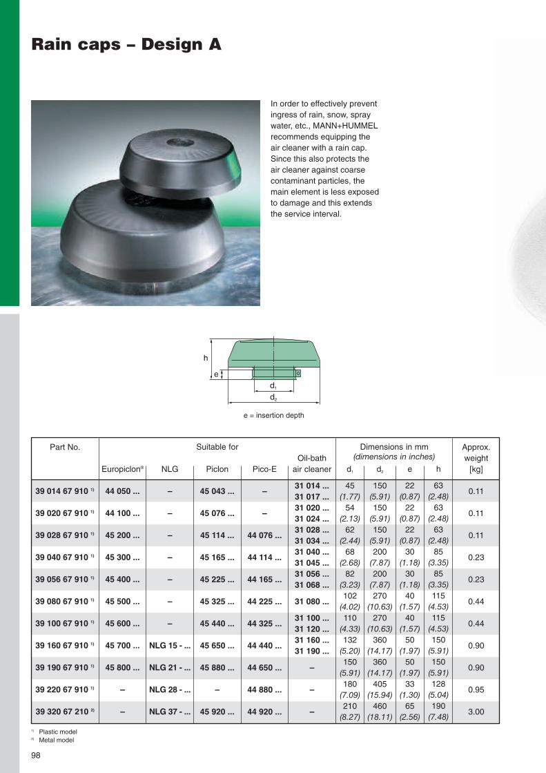
98
Rain caps – Design A
In order to effectively preventingress of rain, snow, spraywater, etc., MANN+HUMMELrecommends equipping theair cleaner with a rain cap.Since this also protects theair cleaner against coarsecontaminant particles, themain element is less exposedto damage and this extendsthe service interval.
e
h
d1
d2
e = insertion depth
1) Plastic model2) Metal model
39 014 67 910 1)
39 020 67 910 1)
39 028 67 910 1)
39 040 67 910 1)
39 056 67 910 1)
39 080 67 910 1)
39 100 67 910 1)
39 160 67 910 1)
39 190 67 910 1)
39 220 67 910 1)
39 320 67 210 2)
Part No. Dimensions in mm(dimensions in inches)
d1
45(1.77)
54(2.13)
62(2.44)
68(2.68)
82(3.23)102
(4.02)110
(4.33)132
(5.20)150
(5.91)180
(7.09)210
(8.27)
d2
150(5.91)150
(5.91)150
(5.91)200
(7.87)200
(7.87)270
(10.63)270
(10.63)360
(14.17)360
(14.17)405
(15.94)460
(18.11)
e
22(0.87)
22(0.87)
22(0.87)
30(1.18)
30(1.18)
40(1.57)
40(1.57)
50(1.97)
50(1.97)
33(1.30)
65(2.56)
h
63(2.48)
63(2.48)
63(2.48)
85(3.35)
85(3.35)115
(4.53)115
(4.53)150
(5.91)150
(5.91)128
(5.04)190
(7.48)
Approx.weight
[kg]
0.11
0.11
0.11
0.23
0.23
0.44
0.44
0.90
0.90
0.95
3.00
Suitable for
Europiclon®
44 050 ...
44 100 ...
45 200 ...
45 300 ...
45 400 ...
45 500 ...
45 600 ...
45 700 ...
45 800 ...
–
–
NLG
–
–
–
–
–
–
–
NLG 15 - ...
NLG 21 - ...
NLG 28 - ...
NLG 37 - ...
Piclon
45 043 ...
45 076 ...
45 114 ...
45 165 ...
45 225 ...
45 325 ...
45 440 ...
45 650 ...
45 880 ...
–
45 920 ...
Pico-E
–
–
44 076 ...
44 114 ...
44 165 ...
44 225 ...
44 325 ...
44 440 ...
44 650 ...
44 880 ...
44 920 ...
Oil-bathair cleaner
31 014 ...31 017 ...31 020 ...31 024 ...31 028 ...31 034 ...31 040 ...31 045 ...31 056 ...31 068 ...31 080 ...31 100 ...31 120 ...31 160 ...31 190 ...
–
–
–

99
Rain caps – Design B
The rain caps are simplypushed on to the dirty air
connection of the air clean-er or onto the air intakeof the dirty air pipe andthen fastened using thetightening strap supplied.
In order to cater for differ-ent installation requirementsand styling, the rain caps areavailable in two different ver-sions.
e
h
d1
d2
1) Plastic model2) Metal model
39 014 67 900 1)
39 020 67 900 1)
39 028 67 900 1)
39 040 67 900 1)
39 056 67 900 1)
39 080 67 900 1)
39 100 67 020 2)
39 160 67 020 2)
45 880 67 100 2)
39 220 67 100 2)
39 320 67 100 2)
39 440 67 100 2)
39 640 67 100 2)
Part No. Dimensions in mm(dimensions in inches)
d1
45(1.77)
54(2.13)
62(2.44)
68(2.68)
82(3.23)102
(4.02)110
(4.33)132
(5.20)150
(5.91)180
(7.09)210
(8.27)240
(9.45)315
(12.40)
d2
92(3.62)110
(4.33)124
(4.88)145
(5.71)172
(6.77)203
(7.99)236
(9.29)292
(11.50)342
(13.46)342
(13.46)410
(16.14)535
(21.06)645
(25.39)
e
22(0.87)
22(0.87)
22(0.87)
22(0.87)
22(0.87)
35(1.38)
40(1.57)
40(1.57)
40(1.57)
45(1.77)
87(3.43)
85(3.35)
86(3.39)
h
53(2.09)
53(2.09)
56(2.20)
63(2.48)
64(2.52)
90(3.54)125
(4.92)138
(5.43)166
(6.54)163
(6.42)223
(8.78)250
(9.84)272
(10.71)
Approx.weight
[kg]
0.07
0.08
0.11
0.12
0.15
0.18
0.82
1.50
2.00
2.20
4.20
4.80
5.80
Suitable for
Europiclon®
44 050 ...
44 100 ...
45 200 ...
45 300 ...
45 400 ...
45 500 ...
45 600 ...
45 700 ...
45 800 ...
–
–
–
–
NLG
–
–
–
–
–
–
–
NLG 15 - ...
NLG 21 - ...
NLG 28 - ...
NLG 37 - ...
–
–
Piclon
45 043 ...
45 076 ...
45 114 ...
45 165 ...
45 225 ...
45 325 ...
45 440 ...
45 650 ...
45 880 ...
–
45 920 ...
44 940 ...
–
Pico-E
–
–
44 076 ...
44 114 ...
44 165 ...
44 225 ...
44 325 ...
44 440 ...
44 650 ...
44 880 ...
44 920 ...
–
45 950 ...
Oil-bathair cleaner
31 014 ...31 017 ...31 020 ...31 024 ...31 028 ...31 034 ...31 040 ...31 045 ...31 056 ...31 068 ...31 080 ...31 100 ...31 120 ...31 160 ...31 190 ...
–
–
–
–
–
e = insertion depth

100
The DualSpin® precleanernewly developed byMANN+HUMMEL offersexcellent separation efficiencywith a simultaneous minimaldrop in pressure. The specialarrangement of both distribu-tors reduces the pressuredrop of the precleaners by upto 50%. Generously dimen-sioned cross-sectional flow
areas almost completely pre-vent clogging – even underunfavourable conditions, suchas with harvesting machines.The DualSpin® is the idealcomplement to the air clean-ers of the NLG line (seepage 23), but it can also becombined with other air clean-ers (e.g. metal air cleaners).
Advantages of theDualSpin® precleaner:
• The highest separationperformance (η > 90%,SAE-C) with scavenging isachieved by connecting anexhaust ejector (see page112), radiator fan or anexternal blower.
• operation with dust dis-charge valve possible as amore economic alternative(η > 85%, SAE-C)
• Different distributor insertsare used to adjust the pre-cyclone within a range of18 m3/min to 50 m3/minideally to the air require-ment of the machine.
• The polygon design of thehousing enables use ofthe proven bracket of theEuropiclon® 700(Part No. 39 700 40 999).
vane to generateair spin
pre-se-parated
air to thefine filter
cyclone housing
dust discharge
vane to generateair spin
contami-natedambientair
Working principle of the DualSpin® precleaner
DualSpin® Precleaners
DualSpin®

101
DualSpin® Precleaners
Fig. 1(Scavenging)
Fig. 2with dust discharge valve 39 000 40 671
Part No. Nominalflow rate[m3/min]
18 – 2525 – 50
without dust discharge valve(Fig. 1)
48 025 75 90048 037 75 910
with dust discharge valve(Fig. 2)
48 025 75 91048 037 75 920
Approx.weight
[kg]
2.42.4
... for flow rates (only DualSpin®) as per ISO 5011
Volume flow V̇ [m3/min]
Flow
resistance[mbar]
0 5 10 15 20 25 30 35 40 45 50
30
40
20
10
0
DualSpin® 25
DualSpin® 37
Dimensions and part numbers
Flow characteristics ...
38.5(1.52)
ø 332(13.07)
508(20.00)
ø 250(9.84)
ø54
(2.13
)
38.5(1.52)
81.5(3.21)
ø 332(13.07)
508(20.00)
ø 250(9.84) 263
(10.35)

102
PrecleanersDust bowls (plastic version)
The proven precleaners fromMANN+HUMMEL are suitablefor extending the service lifeof single-stage air cleanerssuch as the NLG Pico orPico-E. Due to its transparentinsert, it is possible to readthe filling level of the pre-cleaner at any time andaccordingly select the righttime for the service.
The easy and problem-freeemptying of the dust bowl ismade possible by the closingclamp. Precleaners offer pro-tection against ingress ofspray water and rain.
d2
d1
d3
e
h l
vertical mounting
1) ∆p = Flow resistance. When using as precleaner, add 70% of the stated flow resistance to the resistance of the air cleaner fitted downstream.2) e = insertion depth
48 017 67 900
48 024 67 900
48 030 67 900
48 034 67 900
48 048 67 900
48 056 67 900
48 068 67 900
48 096 67 900
48 120 67 900
Part No.Nominal flow rate
[m3/min]
1.4 – 1.7
2 – 2.4
2.8 – 3.4
2.8 – 3.4
4 – 4.5
5.6 – 6.8
5.6 – 6.8
8 – 9.6
10 – 12
at ∆p 1)
[mbar]
7 – 10.5
8.5 – 12
9 – 13
6 – 9
10 – 12.5
12 – 17.5
7 – 10.5
8.5 – 12
11 – 16
Application Dimensions in mm (dimensions in inches)
d1
42.2(1.66)54.2(2.13)62.2(2.45)62.2(2.45)68.2(2.69)82.2(3.24)82.2(3.24)102.2(4.02)110.2(4.34)
d2
164(6.46)164
(6.46)164
(6.46)219
(8.62)219
(8.62)219
(8.62)303
(11.93)303
(11.93)303
(11.93)
d3
175(6.89)175
(6.89)175
(6.89)236
(9.29)236
(9.29)236
(9.29)315
(12.40)315
(12.40)315
(12.40)
e 2)
52(2.05)
52(2.05)
52(2.05)
62(2.44)
62(2.44)
62(2.44)
84(3.31)
84(3.31)
84(3.31)
h
140(5.51)140
(5.51)140
(5.51)167
(6.57)167
(6.57)167
(6.57)208
(8.19)208
(8.19)208
(8.19)
l
150(5.91)150
(5.91)150
(5.91)180
(7.09)180
(7.09)180
(7.09)217
(8.54)217
(8.54)217
(8.54)
Approx.weight
[kg]
0.4
0.4
0.4
1.0
1.0
1.0
1.3
1.3
1.3

103
PrecleanersPrecleaners (metal version)
The metal version of the pre-cleaner is available in twovariations:
• as a throughput precleanerwith integrated rain cap forvertical mounting at the airintake
• as a throughput precleanerfor horizontal installation inthe air intake pipe
el
b
h
d1 d3d2
h2
d3
d2
a
b
h1
d1
e Fig. 1Vertical mounting
Fig. 2Horizontal mounting
1) ∆p = Flow resistance. When using as precleaner, add 70% of the stated flow resistance to the resistance of the air cleaner fitted downstream.2) e = insertion depth
48 024 67 020
48 024 67 030
48 036 67 110
48 048 67 020
48 066 67 110
48 096 67 140
48 132 67 020
48 024 67 140
48 024 67 180
48 036 67 160
48 048 67 220
48 066 67 090
48 096 67 200
48 132 67 120
Part No.Nominal flowrate [m3/min]
2 – 2.8
2.8 – 3.4
3.6 – 4.5
5.6 – 6.8
7.3 – 9.6
10 – 13
16 – 19
2 – 2.8
2.8 – 3.4
3.6 – 4.5
5.6 – 6.8
7.3 – 9.6
10 – 13
16 – 19
at ∆p 1)
[mbar]
7 – 13.5
8.5 – 12.5
11 – 18
14 – 20.5
14 – 24.5
14 – 23.5
13.5 – 19
7 – 13.5
8.5 – 12.5
11 – 18
14 – 20.5
14 – 24.5
14 – 23.5
13.5 – 19
Application Dimensions in mm (dimensions in inches)
a
84(3.31)
84(3.31)
95(3.74)100
(3.94)113
(4.45)113
(4.45)164
(6.46)
–
–
–
–
–
–
–
b
85(3.35)
85(3.35)
85(3.35)
85(3.35)
85(3.35)
85(3.35)125
(4.92)85
(3.35)85
(3.35)85
(3.35)85
(3.35)85
(3.35)85
(3.35)125
(4.92)
d1
54.2(2.13)62.2(2.45)68.2(2.69)82.2(3.24)102.2(4.02)110.2(4.34)132.2(5.20)54.2(2.13)62.2(2.45)68.2(2.69)82.2(3.24)102.2(4.02)110.2(4.34)132.2(5.20)
d2
100(3.94)100
(3.94)114
(4.49)136
(5.35)159
(6.26)158
(6.22)230
(9.06)100
(3.94)100
(3.94)114
(4.49)136
(5.35)158
(6.22)158
(6.22)230
(9.06)
d3
155(6.10)155
(6.10)180
(7.09)215
(8.46)258
(10.16)255
(10.04)368
(14.49)107
(4.21)107
(4.21)120
(4.72)145
(5.71)166
(6.54)166
(6.54)240
(9.45)
e 2)
60(2.36)
60(2.36)
70(2.76)
80(3.15)100
(3.94)110
(4.33)130
(5.12)60
(2.36)60
(2.36)70
(2.76)80
(3.15)100
(3.94)110
(4.33)130
(5.12)
h
–
–
–
–
–
–
–
191(7.52)191
(7.52)198
(7.80)210
(8.27)224
(8.82)220
(8.66)336
(13.23)
h1
10(0.39)
40(1.57)
45(1.77)
40(1.57)
15(0.59)
30(1.18)
35(1.38)
–
–
–
–
–
–
–
h2
300(11.84)
330(12.99)
350(13.78)
400(15.75)
418(16.46)
433(17.05)
615(24.21)
–
–
–
–
–
–
–
l
–
–
–
–
–
–
–
144(5.67)144
(5.67)162
(6.38)203
(7.99)232
(9.13)245
(9.65)370
(14.57)
Approx.weight
[kg]
1.0
1.0
1.4
2.0
2.5
3.5
5.9
0.9
0.7
1.0
1.2
1.6
1.7
3.9
Fig.
1
1
1
1
1
1
1
2
2
2
2
2
2
2

104
Air connecting partsElbow pipes
M 10x1
c
e
b
dida
b
90° elbowsOperating temperature:-40 °C to +100 °C
Fig. 1
Fig. 2
Connection forservice indicator/service switch
39 100 25 99939 100 25 97939 200 25 99939 200 25 97939 300 25 99939 300 25 97939 400 25 99939 400 25 97939 500 25 99939 500 25 97939 600 25 99939 600 25 97939 700 25 99939 700 25 97939 800 25 99939 800 25 97939 930 25 99939 930 25 979
Part No. Dimensions in mm(dimensions in inches)
c
–33
(1.30)
–38
(1.50)
–43
(1.69)
–48
(1.89)
–58
(2.28)
–63
(2.48)
–75
(2.95)
–83
(3.27)
–98.5(3.88)
di
50(1.97)
60(2.36)
70(2.76)
80(3.15)
100(3.94)
110(4.33)
130(5.12)
150(5.91)
196(7.71)
da
55(2.17)
65(2.56)
75(2.95)
85(3.35)
105(4.13)
119(4.69)
135(5.32)
155(6.10)
200(7.87)
e
25(0.98)
25(0.98)
28(1.10)
30(1.18)
35(1.38)
27(1.06)
27(1.06)
27(1.06)
30(1.18)
Con-nection
for
–M 10x1
–M 10x1
–M 10x1
–M 10x1
–M 10x1
–M 10x1
–M 10x1
–M 10x1
–M 10x1
Fig.
1
2
1
2
1
2
1
2
1
2
1
2
1
2
1
2
1
2
b
57(2.24)
62(2.44)
72(2.83)
77(3.03)
92(3.62)
89(3.50)
98.5(3.88)
108.5(4.27)
170(6.69)

105
di
l
e
da
c
l1/2
M 10x1
Straight connectionsOperating temperature:-40 °C to +100 °C
Fig. 1 Fig. 2
Connection for serviceindicator/service switch
39 100 27 99939 100 27 97939 200 27 99939 200 27 97939 300 27 99939 300 27 97939 400 27 99939 400 27 97939 500 27 99939 500 27 97939 600 27 99939 600 27 97939 700 27 99939 700 27 97939 800 27 99939 800 27 97939 930 27 99939 930 27 979
Part No. Dimensions in mm(dimensions in inches)
c
–33
(1.30)–
38(1.50)
–43
(1.69)–
48(1.89)
–58
(2.28)–
63(2.48)
–75
(2.95)–
83(3.28)
–109.5(4.31)
di
50(1.97)
60(2.36)
70(2.76)
80(3.15)
100(3.94)
110(4.33)
130(5.12)
150(5.91)
180(7.09)
da
55(2.17)
65(2.56)
75(2.95)
85(3.35)
105(4.13)
119(4.69)
135(5.32)
155(6.10)
195(7.68)
e
25(0.98)
25(0.98)
28(1.10)
30(1.18)
35(1.38)
27(1.06)
27(1.06)
27(1.06)
45(1.77)
l
68(2.68)
68(2.68)
75(2.95)
78(3.07)
88(3.46)
72(2.83)
72(2.83)
72(2.83)
140(5.51)
Con-nection
for
–M 10x1
–M 10x1
–M 10x1
–M 10x1
–M 10x1
–M 10x1
–M 10x1
–M 10x1
–M 10x1
Fig.
1
2
1
2
1
2
1
2
1
2
1
2
1
2
1
2
1
2
e
l
d1
d2
c
39 300 27 949
39 300 27 959
39 300 27 969
Part No. Dimensions in mm(dimensions in inches)
c
43(1.69)
43(1.69)
43(1.69)
d1
70(2.76)
60(2.36)
50(1.97)
d2
80(3.15)
70(2.76)
70(2.76)
e
13.5(0.53)13.5(0.53)13.5(0.53)
l
89.5(3.52)85.5(3.52)85.5(3.52)
Air connecting partsConnections
Reducer connectionsOperating temperature:-40 °C to +100 °C

Air connecting partsAccordion hoses
106
da
le
di
Accordion hoses withmoulded-on end sleeves(standard model)Material: TPO
Operating temperature:-30 °C to +100 °CMaximum curvature:90° (depending on thevibration load)
da di
le
Accordion hoses(reinforced model)Material: rubber with fabricinsert
Operating temperature:-30 °C to +100 °CMaximum curvature:45° (depending on thevibration load)
39 000 27 164
39 000 27 161
39 000 27 140
39 000 27 139
39 000 27 138
39 000 27 158
39 000 27 152
39 000 27 151
39 000 27 150
Part No. Dimensions in mm(dimensions in inches)
di
40(1.57)
50(1.97)
60(2.36)
70(2.76)
80(3.15)100
(3.94)110
(4.33)130
(5.12)150
(5.91)
da
51(2.01)
62(2.44)
70(2.76)
80(3.15)
90(3.54)100
(3.94)118
(4.65)138
(5.43)165
(6.50)
e
30+5(1.18+0.20)
30+5(1.18+0.20)
30+5(1.18+0.20)
30+5(1.18+0.20)
30+5(1.18+0.20)
40+5(1.57+0.20)
35+5(1.38+0.20)
45+5(1.77+0.20)
45+5(1.77+0.20)
lmin
180(7.09)190
(7.48)190
(7.48)195
(7.68)205
(8.07)230
(9.06)240
(9.45)280
(11.02)300
(11.81)
lmax
250(9.84)285
(11.22)285
(11.22)310
(12.20)340
(13.39)395
(15.55)425
(16.73)500
(19.69)545
(21.46)
39 000 27 205
39 000 27 206
39 000 27 207
39 000 27 208
39 000 27 212
39 000 27 213
39 000 27 214
39 000 27 215
39 000 27 184
39 000 27 346
Part No. Dimensions in mm(dimensions in inches)
di
50(1.97)
60(2.36)
70(2.76)
80(3.15)
90(3.54)100
(3.94)110
(4.33)130
(5.12)150
(5.91)200
(7.87)
da
58(2.28)
68(2.68)
78(3.07)
88(3.46)
98(3.86)108
(4.25)118
(4.65)138
(5.43)158
(6.22)138
(5.43)
e
25(0.98)
50(1.97)
50(1.97)
50(1.97)
50(1.97)
50(1.97)
50(1.97)
50(1.97)
50(1.97)
50(1.97)
l
110±5(4.33±0.20)
215±5(8.46±0.20)
215±5(8.46±0.20)
215±5(8.46±0.20)
215±5(8.46±0.20)
215±5(8.46±0.20)
215±5(8.46±0.20)
215±5(8.46±0.20)
215±5(8.46±0.20)
215±5(8.46±0.20)

107
Air connecting partsStraight couplings in rubber
da di
l
Straight couplingsMaterial:rubber (NBR, 60±5 Shore)with fabric insertOperating temperature:-30 °C to +100 °C39 000 27 203
39 000 27 202
39 000 27 171
39 000 27 198
39 000 27 197
39 000 27 252
39 000 27 196
39 000 27 950
39 000 27 195
39 000 27 103
39 000 27 104
39 000 27 194
39 000 27 193
39 000 27 359
39 000 27 188
39 000 27 192
39 000 27 297
39 000 27 183
39 223 27 111
39 000 27 182
39 000 27 345
39 000 27 306
Part No. Dimensions in mm(dimensions in inches)
di
40(1.57)
50(1.97)
60(2.36)
60(2.36)
70(2.76)
70(2.76)
80(3.15)
80(3.15)
90(3.54)100
(3.94)100
(3.94)100
(3.94)110
(4.33)110
(4.33)130
(5.12)130
(5.12)130
(5.12)150
(5.91)150
(5.91)180
(7.09)200
(7.87)210
(8.27)
da
52(2.05)
63(2.48)
74(2.91)
74(2.91)
84(3.31)
84(3.31)
96(3.78)
96(3.78)106
(4.17)116
(4.57)116
(4.57)118
(4.65)126
(4.96)128
(5.04)148
(5.83)148
(5.83)148
(5.83)166
(6.54)168
(6.61)198
(7.80)218
(8.58)228
(8.98)
l
100(3.94)100
(3.94)100
(3.94)150
(5.91)150
(5.91)80
(3.15)150
(5.91)75
(2.95)150
(5.91)75
(2.95)100
(3.94)150
(5.91)150
(5.91)75
(2.95)100
(3.94)150
(5.91)65
(2.56)150
(5.91)100
(3.94)150
(5.91)200
(7.87)200
(7.87)
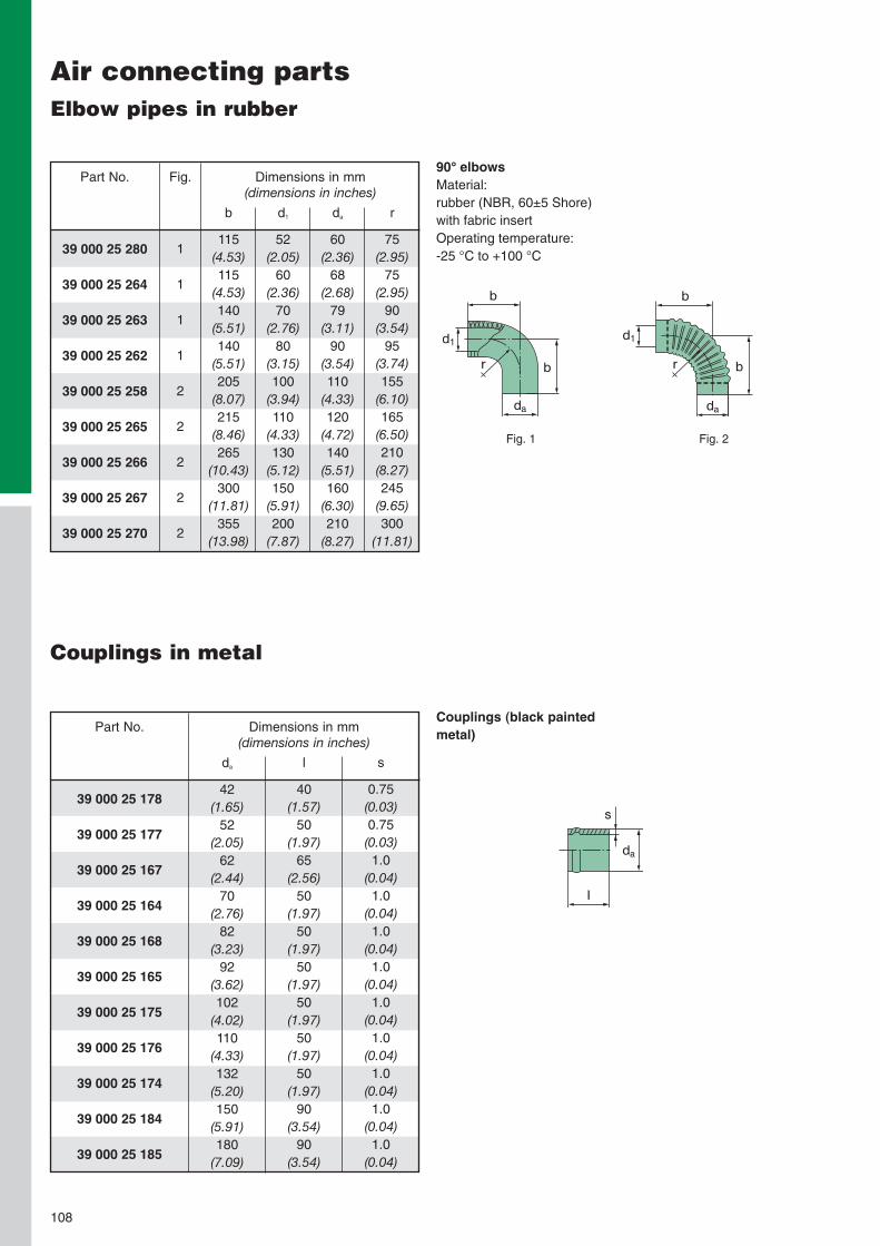
108
Air connecting partsElbow pipes in rubber
90° elbowsMaterial:rubber (NBR, 60±5 Shore)with fabric insertOperating temperature:-25 °C to +100 °C
d1
r b
da
b
Fig. 2Fig. 1
r
d1
b
da
b
39 000 25 280
39 000 25 264
39 000 25 263
39 000 25 262
39 000 25 258
39 000 25 265
39 000 25 266
39 000 25 267
39 000 25 270
Part No. Dimensions in mm(dimensions in inches)
d1
52(2.05)
60(2.36)
70(2.76)
80(3.15)100
(3.94)110
(4.33)130
(5.12)150
(5.91)200
(7.87)
da
60(2.36)
68(2.68)
79(3.11)
90(3.54)110
(4.33)120
(4.72)140
(5.51)160
(6.30)210
(8.27)
r
75(2.95)
75(2.95)
90(3.54)
95(3.74)155
(6.10)165
(6.50)210
(8.27)245
(9.65)300
(11.81)
Fig.
1
1
1
1
2
2
2
2
2
b
115(4.53)115
(4.53)140
(5.51)140
(5.51)205
(8.07)215
(8.46)265
(10.43)300
(11.81)355
(13.98)
Couplings in metal
Couplings (black paintedmetal)
da
s
l
39 000 25 178
39 000 25 177
39 000 25 167
39 000 25 164
39 000 25 168
39 000 25 165
39 000 25 175
39 000 25 176
39 000 25 174
39 000 25 184
39 000 25 185
Part No. Dimensions in mm(dimensions in inches)
da
42(1.65)
52(2.05)
62(2.44)
70(2.76)
82(3.23)
92(3.62)102
(4.02)110
(4.33)132
(5.20)150
(5.91)180
(7.09)
l
40(1.57)
50(1.97)
65(2.56)
50(1.97)
50(1.97)
50(1.97)
50(1.97)
50(1.97)
50(1.97)
90(3.54)
90(3.54)
s
0.75(0.03)0.75(0.03)1.0
(0.04)1.0
(0.04)1.0
(0.04)1.0
(0.04)1.0
(0.04)1.0
(0.04)1.0
(0.04)1.0
(0.04)1.0
(0.04)

109
Air connecting partsConnection pipes and couplings in metal
da di
le
Intermediate pipe (blackpainted metal)only for dirty air intake
da
s
l
Pipes (black painted metal)
31 028 25 831
31 056 25 821
31 080 25 731
39 100 25 991
31 100 25 983
31 160 25 771
Part No. Dimensions in mm(dimensions in inches)
di
62.2(2.45)82.2(3.24)102.2(4.02)110.2(4.34)110.2(4.34)132.2(5.20)
da
62(2.44)
82(3.23)102
(4.02)110
(4.33)110
(4.33)132
(5.20)
e
60(2.36)
80(3.15)
80(3.15)110
(4.33)110
(4.33)110
(4.33)
l
225(8.86)245
(9.65)250
(9.84)200
(7.87)400
(15.75)400
(15.75)
39 000 25 172
39 000 25 182
39 000 25 162
39 000 25 163
39 000 25 173
39 000 25 158
39 000 25 183
39 000 25 166
39 000 25 157
39 000 25 155
Part No. Dimensions in mm(dimensions in inches)
da
42(1.65)
52(2.05)
62(2.44)
70(2.76)
82(3.23)
92(3.62)102
(4.02)110
(4.33)132
(5.20)150
(5.91)
l
500(19.69)
500(19.69)
500(19.69)
500(19.69)
500(19.69)
500(19.69)
500(19.69)
500(19.69)
500(19.69)
500(19.69)
s
0.75(0.03)0.75(0.03)0.75(0.03)0.75(0.03)0.75(0.03)0.75(0.03)0.75(0.03)0.75(0.03)0.75(0.03)0.75(0.03)
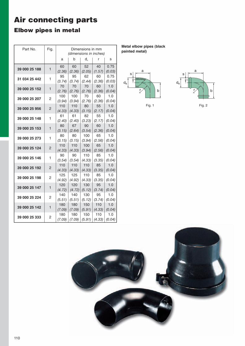
110
Air connecting partsElbow pipes in metal
Metal elbow pipes (blackpainted metal)
da
r
s
b
a
Fig. 2Fig. 1
da
r
s
b
a39 000 25 188
31 034 25 442
39 000 25 152
39 000 25 207
39 000 25 956
39 000 25 148
39 000 25 153
39 000 25 273
39 000 25 124
39 000 25 146
39 000 25 192
39 000 25 198
39 000 25 147
39 000 25 224
39 000 25 142
39 000 25 333
Part No. Dimensions in mm(dimensions in inches)
Fig.
1
1
1
2
2
1
1
1
2
1
2
2
1
2
1
2
a
60(2.36)
95(3.74)
70(2.76)100
(3.94)110
(4.33)61
(2.40)80
(3.15)80
(3.15)110
(4.33)90
(3.54)110
(4.33)125
(4.92)120
(4.72)140
(5.51)180
(7.09)180
(7.09)
b
60(2.36)
95(3.74)
70(2.76)100
(3.94)110
(4.33)61
(2.40)67
(2.64)80
(3.15)110
(4.33)90
(3.54)110
(4.33)125
(4.92)120(4.72)140
(5.51)180
(7.09)180
(7.09)
da
52(2.05)
62(2.44)
70(2.76)
70(2.76)
80(3.15)
82(3.23)
90(3.54)100
(3.94)100
(3.94)110
(4.33)110
(4.33)110
(4.33)130
(5.12)130
(5.12)150
(5.91)150
(5.91)
r
40(1.57)
60(2.36)
60(2.36)
60(2.36)
55(2.17)
55(2.17)
60(2.36)
65(2.56)
65(2.56)
85(3.35)
85(3.35)
85(3.35)
95(3.74)
95(3.74)110
(4.33)110
(4.33)
s
0.75(0.03)0.75(0.03)1.0
(0.04)1.0
(0.04)1.0
(0.04)1.0
(0.04)1.0
(0.04)1.0
(0.04)1.0
(0.04)1.0
(0.04)1.0
(0.04)1.0
(0.04)1.0
(0.04)1.0
(0.04)1.0
(0.04)1.0
(0.04)

111
Air connecting partsAdapter pieces in metal, hose clips
d1 d2
l
Adapter pieces (blackpainted metal)
02 018 01 707
02 018 01 708
02 018 01 709
02 018 01 710
02 018 01 711
02 018 01 712
02 018 01 713
02 018 01 714
02 018 01 715
02 018 01 716
Part No.Hose clips
Clamping range
(diameter)
[mm and inches]
32 – 50(1.26 – 1.97)
40 – 60(1.57 – 2.36)
50 – 70(1.97 – 2.76)
60 – 80(2.36 – 3.15)
70 – 90(2.76 – 3.54)
80 – 100(3.15 – 3.94)
90 – 110(3.54 – 4.33)100 – 120
(3.94 – 4.72)110 – 130
(4.33 – 5.12)120 – 140
(4.72 – 5.51)
02 018 01 717
02 018 01 718
02 018 01 719
02 018 01 720
02 018 01 721
02 018 01 722
02 018 01 723
02 018 01 724
02 018 01 725
02 018 01 728
Part No. Clamping range
(diameter)
[mm and inches]
130 – 150(5.12 – 5.91)140 – 160
(5.51 – 6.30)150 – 170
(5.91 – 6.69)160 – 180
(6.30 – 7.09)170 – 190
(6.69 – 7.48)180 – 200
(7.09 – 7.87)190 – 210
(7.48 – 8.27)200 – 220
(7.87 – 8.66)210 – 230
(8.27 – 9.06)240 – 260
(9.45 – 10.24)
39 000 25 621
39 000 25 622
39 000 25 631
39 000 25 431
39 000 25 461
31 080 25 511
39 000 25 295
39 000 25 193
39 000 25 105
39 000 25 253
39 000 25 325
39 000 25 145
39 000 25 327
Part No. Dimensions in mm(dimensions in inches)
d1
70(2.76)
70(2.76)
80(3.15)
82(3.23)100
(3.94)102
(4.02)110
(4.33)110
(4.33)132
(5.20)132
(5.20)150
(5.91)180
(7.09)200
(7.87)
d2
40(1.57)
60(2.36)
50(1.97)
70(2.76)
70(2.76)
80(3.15)
80(3.15)100
(3.94)102
(4.02)110
(4.33)130
(5.12)150
(5.91)150
(5.91)
l
65(2.56)
56(2.20)
65(2.56)
56(2.20)
75(2.95)
76(2.99)
75(2.95)
70(2.76)
71(2.80)
76(2.99)
86(3.39)
95(3.74)105
(4.13)

112
Exhaust ejectorsMaintenance-free dust scavenging with two-stage air cleaners
The ejector is fitted behindthe exhaust silencer on thetailpipe. The flow energy ofthe exhaust gases generatesa negative pressure in theejector. This enables thepre-separated dust to bescavenged to the ejector andthe dust is then blown outtogether with the exhaustgases.
MANN+HUMMEL ejectorsare designed to providemaintenance-free scavengingof the pre-separated dust intwo-stage air cleaners.In addition to being mainte-nance-free, the ejectors achie-ve a significantly improvedpre-separation efficiency ofthe two-stage air cleaner.This enables a considerablylonger filter service life (up to60%).
In order to avoid this, thescavenging should either bemade in a closed area (cool-ing air shaft, scavengingunder engine bonnet) or in-stalled upstream with a basketsieve.When using an ejector, careshould also be taken that themaximum permissible exhaust
Installation instructions
The connection pipe betweenthe air cleaner and ejectorshould be as short as possibleand not have any tight elbowswhich would increase flowresistance. Coarse contami-nant particles in the intake air(e.g. awns, fibres, stems orleaves) can lead to cloggingin the air cleaner.
back pressure specified bythe engine producer is notexceeded.In addition, in all operationalconditions there must be apressure drop to the ejectorin order to prevent exhaustgas being sucked in. In caseof doubt we recommend useof a non-return adapter.
Installation example
Europiclon® Air cleaner
Exhaust silencer MANN+HUMMEL Ejector
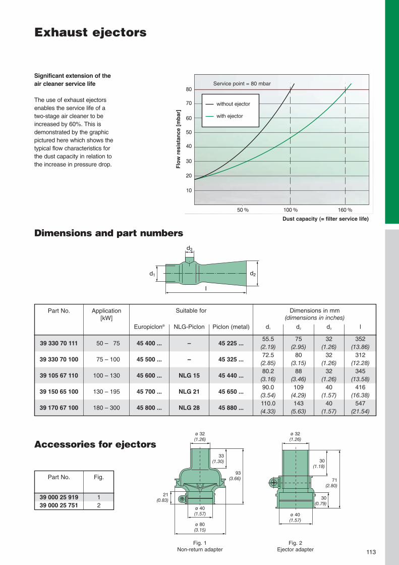
Exhaust ejectors
113
Significant extension of theair cleaner service life
The use of exhaust ejectorsenables the service life of atwo-stage air cleaner to beincreased by 60%. This isdemonstrated by the graphicpictured here which shows thetypical flow characteristics forthe dust capacity in relation tothe increase in pressure drop.
Dimensions and part numbers
80
100 %50 % 160 %
60
70
50
30
40
20
10
l
d3
d1 d2
without ejector
with ejector
Service point = 80 mbar
Flow
resistance[mbar]
Dust capacity (= filter service life)
Accessories for ejectors
Part No.
39 000 25 91939 000 25 751
Fig.
12
ø 32(1.26)
ø 32(1.26)
21(0.83)
33(1.30)
93(3.66)
ø 40(1.57)
ø 80(3.15)
30(1.18)
ø 40(1.57)
30(0.79)
71(2.80)
Fig. 1Non-return adapter
Fig. 2Ejector adapter
39 330 70 111
39 330 70 100
39 105 67 110
39 150 65 100
39 170 67 100
Part No.
50 – 75
75 – 100
100 – 130
130 – 195
180 – 300
Application[kW]
Dimensions in mm(dimensions in inches)
d1
55.5(2.19)72.5(2.85)80.2(3.16)90.0(3.54)110.0(4.33)
d2
75(2.95)
80(3.15)
88(3.46)109
(4.29)143
(5.63)
d3
32(1.26)
32(1.26)
32(1.26)
40(1.57)
40(1.57)
l
352(13.86)
312(12.28)
345(13.58)
416(16.38)
547(21.54)
Suitable for
Europiclon®
45 400 ...
45 500 ...
45 600 ...
45 700 ...
45 800 ...
NLG-Piclon
–
–
NLG 15
NLG 21
NLG 28
Piclon (metal)
45 225 ...
45 325 ...
45 440 ...
45 650 ...
45 880 ...

114
Service indicatorsLevel of dirt accumulation readable at any time
The MANN+HUMMEL serviceindicator allows you to readthe current level of dirt accu-mulation in the air cleaner,even when the engine is not inoperation. The yellow indica-ting piston catches on a scaleof 12 snap-in positions. In thetriangular display, the remain-ing service life of the filter isdisplayed, in relation to theincreased clogging of the filterelement.
The service indicator is in-sensitive to the intake airpulsations of the engine, ex-cluding the possibility of afalse indication. Maintenanceis necessary when the yellowpiston reaches the red zone.After maintenance has beencarried out, the indicator levelis readjusted to "zero" bypressing the reset button.
39 035 70 91139 050 70 91139 060 70 91139 065 70 91139 080 70 911
Part No. snaps into place at gauge pressure
[mbar]
35±350±460±465±580±5
[kPa]
3.5±0.35.0±0.46.0±0.46.5±0.58.0±0.5
M 10x1
ø 46.7(1.84)
1.2(0.05)
51.5(2.03)
Specifications• Material: PC• Permissible operating temperature: -30 °C to +100 °C• Switching pressure (negative pressure): 35 mbar to 80 mbar
(3.5 kPa to 8 kPa)
The 90° connecting flangeallows nearly any fitting posi-tion. The red indicating pistonsnaps into position upon
reaching the maximum valuepossible, signalling that main-tenance is needed.After maintenance has been
carried out, the indicatingpiston is readjusted to thestart position by pressing thereset button.
39 000 62 92439 000 62 92539 000 62 92639 000 62 927
Part No. snaps into place at gauge pressure
[mbar]
35±350±665±780±8
[kPa]
3.5±0.35.0±0.66.5±0.78.0±0.8
Specifications• Material: PA• Permissible operating temperature: -40 °C to +100 °C• Switching pressure (negative pressure): 35 mbar to 80 mbar
(3.5 kPa to 8 kPa)
M 10x1
Sight glass forsignal ring Flange
Reset button
18(0.71)
35(1.38)
28(1.10)
10(0.39)
7(0.28)
40(1.57)
62(2.44)
8.5(0.33)
Service indicators with 90° flange

M 10x1For retro-fitting in the clean air pipe
1 Connection nipple Part No.: 21 010 15 1212 Felt disc Part No.: 23 005 31 171
Ensure that the felt disc is fitted to the nipplebefore installing.
Pipe connector Pipe connectorPart No.: 02 011 11 001 Part No.: 02 011 04 005
Hose connector Hose connectorPart No.: 39 000 47 211 Part No.: 39 000 47 221
2
ø 5(0.20)
ø 6(0.24)
1
ø 6(0.24)
18(0.71)
17(0.67)
8(0.32)
Service switchesElectrical monitoring of the level of accumulated dirt
115
The electrical service switchmonitors the level of accumu-lated dirt in the air cleanerand sends an electrical signalwhen maintenance is required.This enables constant super-vision of the state of the aircleaner and maintenance onlytakes place when it is reallynecessary.
This removes potential dam-age to equipment which mayoccur through frequent andcareless maintenance actions.
Models
MANN+HUMMEL serviceswitches are available with anumber of different connectionthreads and plug connectorsversions.
Technical instructions
Thanks to the completelyinsulated and fully enclosedcontact insert, the switch isinsensitive to dust or humidi-ty. The system is not mechan-ical but pressure-dependent
so that possible tolerances ofthe components do not affectthe accuracy of the switch.The heart of the system is akick-over spring that makesreadjustment of the switching
point unnecessary. Thespring contacts are not affec-ted by contact erosion. As aresult of the hysteresis be-tween the points for switchingand switching back, contact
Specifications• Material: polyamide 6 GF 30• Permissible operating temperature: -30 °C to + 120 °C• Switching pressure (negative pressure): 35 mbar to 80 mbar (3.5 kPa to 8.0 kPa)• Max. switching capacity: 6W/24V DC (ohmnique load, Umax = 24V, Imax = 0.25 A)
Accessories for external mounting
Installation examples: Connection on air cleaner(generally existing)
Parts for pipe connection
Parts for hose connection
fluttering is reduced to aminimum. The service switchshould not be fitted in a hang-ing position so as to preventingress of any condensedwater into the air pipe.

116
Service switcheswith connection for flat plug
Make contactPart No.
39 035 70 90239 050 70 90239 055 70 90239 060 70 90239 065 70 90239 070 70 90239 080 70 902
Service switch internal thread M 10x1
switches at gauge pressure
[mbar]
35±350±355±360±365±370±480±4
[kPa]
3.5±0.35.0±0.35.5±0.36.0±0.36.5±0.37.0±0.48.0±0.4
Make contactPart No.
39 035 70 95239 050 70 95239 055 70 95239 060 70 95239 065 70 95239 070 70 95239 080 70 952
Service switch external thread M 10x1
switches at gauge pressure
[mbar]
35±350±355±360±365±370±480±4
[kPa]
3.5±0.35.0±0.35.5±0.36.0±0.36.5±0.37.0±0.48.0±0.4
Make contactPart No.
39 035 70 96239 050 70 96239 055 70 96239 060 70 96239 065 70 96239 080 70 962
Service switch external thread 1/8“-27 NPTF
switches at gauge pressure
[mbar]
35±350±355±360±365±380±4
[kPa]
3.5±0.35.0±0.35.5±0.36.0±0.36.5±0.38.0±0.4
M 10x1
M 10x1
1/8"-27 NPTF
Suitable for AMP plugconnector 926521
Suitable for AMP plugconnector 926521
Suitable for AMP plugconnector 926521
ø 48(1.89)
14.7(0.58)
ø 20(0.79)
10(0.39)
11.8(0.46)
34.8(1.37)
14.7(0.58)
ø 48(1.89)
37(1.46)
23(0.91)
9(0.35)
14.7(0.58)
ø 48(1.89)
37.5(1.48)
23(0.91)
9.5(0.35)
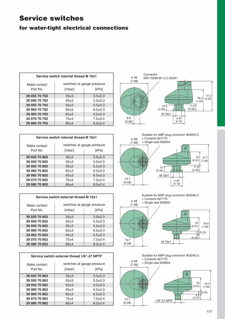
1/8"-27 NPTF
M 10x1
M 10x1
Suitable for AMP plug connector 963040-3+ Contacts 927770+ Single seal 828904
Suitable for AMP plug connector 963040-3+ Contacts 927770+ Single seal 828904
Suitable for AMP plug connector 963040-3+ Contacts 927770+ Single seal 828904
Service switchesfor water-tight electrical connections
117
Make contactPart No.
39 035 70 70239 050 70 70239 055 70 70239 060 70 70239 065 70 70239 070 70 70239 080 70 702
Service switch internal thread M 10x1
switches at gauge pressure
[mbar]
35±350±355±360±365±370±480±4
[kPa]
3.5±0.35.0±0.35.5±0.36.0±0.36.5±0.37.0±0.48.0±0.4
Make contactPart No.
39 035 70 80239 050 70 80239 055 70 80239 060 70 80239 065 70 80239 070 70 80239 080 70 802
Service switch internal thread M 10x1
switches at gauge pressure
[mbar]
35±350±355±360±365±370±480±4
[kPa]
3.5±0.35.0±0.35.5±0.36.0±0.36.5±0.37.0±0.48.0±0.4
Make contactPart No.
39 035 70 85239 050 70 85239 055 70 85239 060 70 85239 065 70 85239 070 70 85239 080 70 852
Service switch external thread M 10x1
switches at gauge pressure
[mbar]
35±350±355±360±365±370±480±4
[kPa]
3.5±0.35.0±0.35.5±0.36.0±0.36.5±0.37.0±0.48.0±0.4
Make contactPart No.
39 035 70 86239 050 70 86239 055 70 86239 060 70 86239 065 70 86239 070 70 86239 080 70 862
Service switch external thread 1/8“-27 NPTF
switches at gauge pressure
[mbar]
35±350±355±360±365±370±480±4
[kPa]
3.5±0.35.0±0.35.5±0.36.0±0.36.5±0.37.0±0.48.0±0.4
M 10x1
ø 48(1.89)
ConnectorDIN 72585-B1-2.2-AG/K1
9.6(0.38)
ø 20(0.79)
10(0.39)
11.8(0.46)
36.4(1.43)
51.2(2.02)
ø 48(1.89)
14.7(0.58)
10(0.39)
ø 20(0.79)
11.8(0.46)
23(0.91)
47.7(1.88)
ø 48(1.89)
14.7(0.58)
49.9(1.96)
23(0.91)
9(0.35)
5 (0.20)
ø 48(1.89)
14.7(0.58)
50.4(1.98)
23(0.91)
9.5(0.37)
5 (0.20)

118

Technical Appendix
119

EjectorA component in the exhausttract of the engine where across-section constriction(using the Venturi principle)generates a negative pres-sure for the continuous scav-enging of the air cleaner.
Europiclon®MANN+HUMMEL brandname for a two-stage aircleaner line in plastic.
Flow resistance ∆p[mbar] or [kPa]. Measuredvariable for the pressure dropof a filter.
Laboratory dust capacity[g]. The measured quantityof a defined test dust whichis added to a filter underlaboratory conditions untilthe service point is reached.
Clean air pipePipe after air cleaner throughwhich cleaned air is fed tothe engine/compressor etc.
Dirty air intakeDirty air pipe before theair cleaner through whichambient air (unfiltered) issucked in.
DualSpin®MANN+HUMMEL brandname for a precleaner linefor use under heavy dustconditions.
Dust discharge valveValve on the housing of two-stage air cleaners whichdischarges the separateddust from the air cleanerhousing.
120
Glossary of filtration terms
Laboratory service life[h]. The time measured underlaboratory conditions that anair cleaner with air flowingthrough it and loaded withdust will reach a defined flowresistance. The test dust, dustconcentration and volumeflow must be defined.
Main elementAlso called the filter elementor primary element. An aircleaner insert consisting of afilter medium and seal whicheffect the fine filtration in adry air cleaner.
NLGMANN+HUMMEL brandname for an air cleaner linein plastic. This line is avail-able as a single-stage or two-stage air cleaner.
Nominal flow rate V̇Describes a design consi-deration for an air cleaner.Depending on the designor line the nominal flow ratedescribes the respectivevolume flow where the filterwill show a pressure drop of25 mbar to 30 mbar.
PiclonMANN+HUMMEL brandname for a two-stage aircleaner line in metal or ingeneral for a two-stage ver-sion of a dry air cleaner (e.g.NLG Piclon).

121
PicoMANN+HUMMEL brandname for a single-stage aircleaner line in metal or ingeneral for a single-stageversion of a dry air cleaner(e.g. NLG Pico).
PicolightMANN+HUMMEL brandname for a single-stage aircleaner line without housing.
PicolinoMANN+HUMMEL brandname for a single-stage aircleaner line in plastic.
PrecleanerCentrifugal force separatorto filter out particles from theintake air.
Pre-separation efficiency[%]. Amount of dust sepa-rated in the first stage of atwo-stage air cleaner.
PulsationPressure oscillations in theintake channel of an engineor a compressor.
Secondary elementAn additional air cleanerinsert which is fitted down-stream from the main ele-ment and which preventsingress of dust into the cleanair pipe during maintenancework or when the main ele-ment is defective.
Service indicatorMounted device which indi-cates the time when toservice.
Service life[h]. Life of filter determinedin the field before the filterneeds servicing.
Service switchMounted device which trig-gers an electric signal whenthe time for a service isreached which in turn setsoff an audio or visual warningsignal.
Single-stage air cleanerAir cleaner without presep-aration. Available with orwithout a secondary element.
Two-stage air cleanerAn air cleaner with an inte-grated filtration stage for pre-separation of dust from theintake air before subsequentfine filtration.
Volume flow V̇[m3/min]. Quantity whichflows through filter per unitof time, also called the volu-metric flow.
Glossary of filtration terms

122
Criteria for dimensioning the size of air cleaners
Specification of filter size
the ratio of all particles sepa-rated to the total quantity ofparticles fed to the air clea-ner. MANN+HUMMEL dry aircleaners offer the followingvalues for this characteristicwhen internationally recog-nised SAE coarse and SAEfine test dusts are used:
η SAE coarse ≥ 99.9%η SAE fine ≥ 99.5%
The correct definition of aircleaner quality with respectto the size of the largest par-ticle allowed to pass throughis provided by fractionalseparation efficiencies; theseindicate a filter’s separationperformance in relation to the
Separation efficiency
The most important task ofa dry air cleaner is to ensuresufficient protection of the en-gine against wear under allpossible dust conditions, i.e.,the separation efficiency ofthe air cleaner must be ofsuch a high standard thatan engine fitted with it willdemonstrate a wear patternin dusty conditions similarto that of an engine runningon completely particle-freeintake air. The specificationof an air cleaner’s qualitywith respect to the quantitytransmitted is indicated withthe so-called overall sepa-ration efficiency η, which is
particle size. The valuesshown in Fig. 1 apply toMANN+HUMMEL dry aircleaners and were obtainedon test rigs using SAE testdusts. Note the high probabi-lity of separation found even
for 1 µm particles, and thevirtually certain separation ofparticles larger than 3 µm insize. The values given aboveare valid for the entire designrange under test rig condi-tions.
In order to ensure a highdust-holding capacity, thepaper pleats are providedwith surface contours thatmaintain clearance, guaran-tee an unhindered flow ofdust-laden air into the pleats,and simultaneously preventthe pleats from stickingtogether.
Service life
Another important requirementfor dry air cleaners is, inaddition to specified sepa-ration efficiencies, a high dust-holding capacity. This qualityfactor – also referred to asservice life – can be definedin terms of the quantity ofdust taken up by the filterwithin a given increase inair-flow resistance.
1 5 6432Separationefficiency%SAEfinedust
Equivalent particle size [µm]
99.9
99.8
99.5
99
98
Use a factor of 0.9 for thevolumetric efficiency of 4-stroke and 0.7 for 2-strokeS.I. engines. For turbo-charged engines, pleaseconsult the manufacturer forthe volumetric efficiency.
Step 1: Determine the airrequirement
The size of the air cleanerdepends primarily on themaximum air requirement (V̇)of the engine. Please askyour equipment and enginemanufacturer.The air requirement can alsobe determined from the en-gine data, i.e. piston-sweptvolume, rotational speed,number of cylinders and vo-lumetric efficiency, by usingthe following equation (1):
4 stroke engines:(V̇ ) = swept volume · rotational speed · volumetric efficiency m3
2 · 1000 min
2 stroke engines:(V̇ ) = swept volume · rotational speed · volumetric efficiency m3
1 · 1000 min
with swept volumes in [dm3], rotational speed in [min-1]
[ ]
[ ]
Equation (1): Air requirement (V̇)
Fig. 1: Separation efficiencies

If necessary data is not avail-able for the previous calcula-tion, the air requirement canbe estimated using the fol-lowing approximations:
Diesel engines*1 kW approx. 0.08 m3/min(1 HP approx. 0.06 m3/min)
Turbocharged Dieselengines*1 kW approx. 0.09 m3/min(1 HP approx. 0.065 m3/min)
Petrol engines*1 kW approx. 0.07 m3/min(1 HP approx. 0.05 m3/min)
* We can assume that mo-dern Diesel and petrolengines which fulfil theexhaust emission regula-tions of today and tomorrowwill have an increase in theair requirement of around10%.
Example 2:
Turbocharged Diesel enginewith 107 kW power
V̇ = (107 · 0.09) + 10 %V̇ = 9.63 + 10 %V̇ = 10.6 m3/min
123
Step 2: Determine thepulsation factors
With a small number of cyl-inders, flow pulsations occurin the intake system. Thecorresponding varying ve-locities must be taken intoaccount when determiningthe size of the filter. The useof so-called pulsation factors(Fig. 2) can be used to over-come this problem.
No. of cylinders12345 and more
Pistoncompressors 1)
1.51.21.111
2 stroke engines1.51.21.111
4 stroke engines21.41.31.11
Pulsation factors for dry air cleaners (aspirating engines)
The pulsation factor is 2.0 for all grab-controlled compressors
No. of cylinders12345 and more
4 stroke engines321.41.21
2 stroke engines21.41.21.11
Pulsation factors for oil-bath air cleaners
1)
Step 3: Determine thedesign flow rate
With 1-4 cylinders, the airrequirement obtained abovemust be multiplied with thecorresponding pulsationfactor to determine the filtersize. This results in the fol-lowing equation (2):
For naturally aspirated en-gines with 5 or more cylinders,and for all turbocharged en-gines, the air requirementcorresponds to the designflow rate of the filter, i.e., the
filter size is specified directlywith the determined designflow rate (m3/min). The no-minal flow rate of the filter(m3/min) is a deciding factorfor the air cleaner size.
Design flow rate = air requirement · pulsation factor m3
minwith air requirement in [m3/min]
[ ]
Fig. 2: Pulsation factors
Equation (2): Design flow rate
Example 1:
3 cylinder 4 stroke DieselengineSwept volume: 1.7 dm3
Rotational speed: 2100 rpm
1. Air requirement afterequation (1)
V̇ = 1.7 · 2100 · 0.9 / 2000V̇ = 1.6 m3/min
2. Pulsation factor fromthe table
Dry air cleaner3 cylinder, 4 stroke enginePulsation factor = 1.3
3. Design flow rate afterequation (2)
V̇ = 1.6 m3/min · 1.3V̇ = 2.1 m3/min
Result:The design flow rate of theengine is 2.1 m3/min.
Specification of filter size
Estimation of the design flow rate based onengine breake power

124
Defining the dust capacity
All MANN+HUMMEL air clea-ners are tested on specialtest benches. The resultingdata allows a uniform basisfor comparison for the dustcapacity of the various filtertypes and sizes.This offers true comparisonpossibilities for filters from dif-ferent sources and enables aservice life estimation for usein practice.On the following pages themean value curves of theeffective dust-holding capa-city for the described filtersare illustrated based on thenominal volume flow (V̇).
These values relate to a stan-dard SAE C test dust with anexactly defined particle sizedistribution and were deter-mined with a dust concentra-tion of 1 g/m3. Here one canspeak of a so-called labora-tory service life.In order to calculate the wor-king service life in hours ordriving kilometres from thelaboratory dust-capacity datafor a given dry air cleaner, thedust concentration prevailingin practice must be known.Extensive tests have led tothe overview on this page(Fig. 3):
Construction machines (front-end loaders,track vehicles, mobile compressors): 35
Buses with intake at the rear in normalEuropean road traffic: 5Buses with intake at the rear in roadtraffic outside Europe: 30
Mean dust concentration in [mg/m3]
Truck in normal European road traffic: 0.6Truck in road traffic outside Europe: 3Off-highway truck (construction site use): 8
Sweeping vehicles: 8Agricultural machines in central Europe(agriculture without periods of drought): 5Agricultural machines in areas outsideEurope in single operation: 15
Agricultural machines used in fleets: 50
Quick-moving track vehicles: 100
Fig. 3: Dust concentrations in practice
Calculation of hours ofoperation in practice
Equation (3) is used in orderto calculate the hours of op-eration in practice from thelaboratory dust capacities:
Driving kilometres = hours of operation · speed
with speed in km/h
Hours in practice = laboratory dust capacity · 1000dust concentration · air requirement · 60
with dust capacity in [g]dust concentration in [mg/m3]air requirement in [m3/min]
Equation (3): Hours of operation
Using equation (4) it is possi-ble to calculate the drivingkilometres from the hours ofoperation:
Equation (4): Driving kilometres
Example 3:
A construction machinewith an air requirement of12 m3/min is equipped witha filter with a laboratory dustcapacity of 5800 g. The ex-pected hours of operationare to be calculated.
According to equation (3):
=
Hours of operation = 230 hours
5800 · 100035 · 12 · 60
Hours ofoperation

125
Defining the dust capacity
Application example
Vehicle dataVehicle type: TractorLocation: Central Europe,but designed for use in har-vesting fleet
Engine dataFuel: DieselType: Aspirating engineEngine capacity: 5.3 dm3
Nominal rot. speed: 2300 rpmNo. cylinders: 4
RequirementsInitial resistance:30 mbar max.End resistance:65 mbar maxRequired service life:min. 200 operating hours
Step 1:Defining the air require-ment
According to equation (1):
Step 2:Determining the pulsationfactors
From Fig. 2 we can see:
V· =
V· = 5.49 m3/min
5.3 · 2300 · 0.92 · 1000
No. of cylinders12345 and more
Pistoncompressors 1)
1.51.21.111
2 stroke engines1.51.21.111
4 stroke engines21.41.31.11
Pulsation factors for dry air cleaners (aspirating engines)
Step 3:Defining the design flowrate
Acc. to equation (2):
V̇ = 5.49 m3/min · 1.1
V̇ = 6.0 m3/min
Step 4:Filter recommendation
Due to the operating condi-tions a Europiclon® 300 isrecommended with a secon-dary element and a smalldust discharge valve.
Part No:45 300 92 911
In the resistance diagram onpage 25 the initial pressuredrop of the filter can be readto be 30 mbar.
Step 5:Laboratory dust capacityfrom the diagram
From the diagram on page 15a dust capacity of 4000 g canbe read.
0 1000 2000 3000 4000 5000
Dust capacity PTI coarse [g]
Flow
resistance[mbar] 80
706050403020100
Step 6:Dust concentration inpractice
Acc. to Fig. 3 "Dust concentrati-ons" there is a concentration of50 mg/m3 for fleet operations.
Step 7:Calculation of hours ofoperation
According to equation (3):=
Hours of operation = 222 hours
4000 · 1000
50 · 6.0 · 60
Hours of
operation

126
General instructions for installation andmaintenance
• The filters should be fittedas close to the engine aspossible and should be eas-ily accessible for servicing.
• Enough room must be leftfor filter element removal.
• Service indicators shouldbe clearly visible, and insome cases service swit-ches are recommendedwith external service dis-plays.
Filter installation
There are a number of impor-tant points to be observedwhen installing dry air clea-ners:
• The temperature stabilityof MANN+HUMMEL filterelements covers -40 °C to+80 °C in continuous ope-ration with short peaks ofup to +100 °C (e.g. due toheating up from the swit-ched-off engine).
• The air cleaner should beinstalled in such a way thatthe clean air pipes (theconnection between aircleaner and engine) do notneed to be removed underany circumstances duringair cleaner or engine servi-cing.
• Avoid positioning the aircleaner in an area wherewater is splashed or a lotof dust is raised (e.g. inareas where the wheelsspray).
• The air cleaner should bemounted on the vehicleframe or some sturdy bodycomponent. The matchingbrackets shown on page95 to 97 are recommen-ded for this purpose. If theair cleaner is subjected toheavy impacts, it shouldbe installed on an elasticmounting.
• The air cleaner should beinstalled where it is protec-ted against collision dam-age (observe the gradientof slope). This is especiallyvalid for off-road vehicles.
• The intake of hot air (e.g.radiator cooling air) andexhaust gases should beavoided. Intake of exhaustsoot drastically shortensthe air cleaner service in-tervals.
• The intake openings shouldbe as large as possible.Intake-flow velocities shouldnot exceed 3 m/sec.
Air intake
• The air intake should belocated in a low-dust area.This generally means ashigh as possible and, foron-road vehicles, as farforward as possible (seeFig. 4).
• The air intake should notbe where the wheels sprayor under the floor.
• Screening against theentrance of water (e.g.while the vehicle is beingwashed) and rainfall isrequired. Rain caps arerecommended.
Air pipes
• Only use suitable materialfor these pipes. This appliesin particular to the clean airpipe. MANN+HUMMELaccessories fulfil theserequirements.
• The line cross sectionsshould not be selectedsmaller than the connec-tion cross sections on theair cleaner.
• Due to their being attachedto different parts of thevehicle (engine, chassis,driver’s cab), the connec-tion pieces in the air intakesystem are subject to rela-tive movement. This shouldbe compensated by fittingflexible intermediate linksbetween the air intakepipes. Spiral and rubberaccordion hoses are re-commended for this pur-pose. The pipes are not tobe welded to the inlet andoutlet connections on theair cleaner. Rubber hosesare also recommended forthese connections.
• Pipes should be fitted toavoid damage from scuff-ing, melting of rubberhoses on hot exhaustcomponents or damagethrough other causes, suchas stones thrown up fromvehicle wheels. When fit-ting these dirty air pipes,care should be taken toensure that water pocketscannot form. Drain pointsmust be provided if neces-sary.
Height above the ground (m)
Relative
dustconcentration%
0.5 1.0 1.5 2.0 2.5 3.0
Fig. 4: Dust concentration depending on the position of theair intake
150
100
50

General instructions for installation andmaintenance
127
• The material used for thepipes must retain its shapeand remain airtight duringoperation (it is a vacuumsystem). This applies inparticular to all flexible con-nections. Fabric-ply rubberhoses retain their shapewell and are also sufficientlyresistant to oil, fuel, ozoneand weather and areadequately temperature-resistant.
Clean air pipes
The clean air pipes must beairtight. Leaky clean air pipesallow dirt to bypass the filterand enter the engine, causingpremature wear. Therefore,particular attention should bepaid to the clean air pipes.The following points shouldbe observed:
• The clean air pipes shouldbe as short as possible anduse the least number ofjoints.
• Hose clamps for securingthe connecting elementsmust be sufficiently wideand strong, and must notcut into the hoses. In theclosing area they should bedesigned so that no foldingof the hose is possible.
• Pipes and couplings mustnot have any rough weldingor casting seams, or over-lapping metal. Connectingsleeves for mounting rubberhoses or elbows should be
provided with a sealingbead. The length of overlapmust be sufficient (at least30 mm).
• Self-made clean air pipesshould be descaled andvarnished on the inside be-fore being fitted.
• Clean air pipes must bechecked for leaks at regularintervals. Faulty connectioncomponents must be re-placed.
• In order to clean, positiona pipe with an end bent byapprox. 90° on the end ofcompressed-air pistol. Thepipe must be long enoughto reach to the bottom ofthe filter element. Carefullyblow out the filter elementwith dry compressed air(max. 5 bar) from the in-side to the outside, or fromthe clean air side to thedirty air side until there isno more development ofdust. The end of the pipemust not touch the element(see Fig. 5).
• Next, carefully examine thefilter for possible damage.
• Never beat or knock thefilter element as this willdamage it and there will bea danger of damage to theengine.
• Please note that the second-ary element is never clean-ed, but must be alwaysreplaced.
• Please note that a cleanedelement will never matchthe service life and perfor-mance of a new element.
Servicing
An air cleaner service be-comes necessary when theMANN+HUMMEL filter ele-ment is exhausted.The following basic principlesshould be observed:
• Always select the servicepoint according to the ser-vice indicator or serviceswitch. A regular inspectionor cleaning of the element,as is sometimes practisedin the field, is more likely tobe damaging than usefulas there is a risk that theelement will be damagedand that dust will gainaccess to the engine.
• MANN+HUMMEL alwaysrecommends exchangingrather than cleaning thefilter element in order toavoid damage and ensuremaximum engine protec-tion.
• If, however, cleaning can-not be avoided, care shouldbe taken that the filter ele-ment is not washed out.
Fig. 5: Cleaning the
main element
• After servicing the filterelement carefully wipe outthe inside of the housingand the seal contact sur-face with a moist cloth.Take care that no dust ordirt gains access to theclean air side of the aircleaner.
• When fitting the filter ele-ment take care that it iscorrectly positioned in thehousing so that the functionof the seals is not impaired.
• Please note that enginedamage can cause consid-erable costs and stoppagetimes which can make thecost of a new filter elementappear insignificant.
• There are detailed mainte-nance instructions availablefor the various filter linesfrom MANN+HUMMELwhich offer detailed instruc-tions on the correct mainte-nance of your filter. Pleaseask us – and we will behappy to answer yourquestions.

128
Conversion table
Pressure5 mbar = 0.5 kPa = 2 “ H2O10 mbar = 1.0 kPa = 4 “ H2O15 mbar = 1.5 kPa = 6 “ H2O20 mbar = 2.0 kPa = 8 “ H2O25 mbar = 2.5 kPa = 10 “ H2O30 mbar = 3.0 kPa = 12 “ H2O35 mbar = 3.5 kPa = 14 “ H2O40 mbar = 4.0 kPa = 16 “ H2O45 mbar = 4.5 kPa = 18 “ H2O50 mbar = 5.0 kPa = 20 “ H2O55 mbar = 5.5 kPa = 22 “ H2O60 mbar = 6.0 kPa = 24 “ H2O
62.5 mbar = 6.3 kPa = 25 “ H2O65 mbar = 6.5 kPa = 26 “ H2O70 mbar = 7.0 kPa = 28 “ H2O75 mbar = 7.5 kPa = 30 “ H2O80 mbar = 8.0 kPa = 32 “ H2O
Weight10 g = 0.35 ounces25 g = 0.88 ounces50 g = 1.75 ounces100 g = 3.5 ounces250 g = 8.8 ounces500 g = 17.6 ounces1000 g = 1 kg = 35.3 ounces = 2.2 lb2000 g = 2 kg = 70.5 ounces = 4.4 lb3000 g = 3 kg = 105.8 ounces = 6.6 lb4000 g = 4 kg = 141.1 ounces = 8.8 lb5000 g = 5 kg = 176.4 ounces = 11.03 lb10000 g = 10 kg = 22.05 lb20000 g = 20 kg = 44.1 lb50000 g = 50 kg = 110.23 lb
Volume flow m3/min →→ cfm1 m3/min = 35.3 cfm
1.7 m3/min = 60.0 cfm2 m3/min = 70.6 cfm3 m3/min = 105.9 cfm4 m3/min = 141.3 cfm
4.5 m3/min = 158.9 cfm6 m3/min = 211.9 cfm8 m3/min = 282.5 cfm10 m3/min = 353.1 cfm12 m3/min = 423.8 cfm15 m3/min = 529.7 cfm18 m3/min = 635.7 cfm20 m3/min = 706.3 cfm21 m3/min = 741.6 cfm24 m3/min = 847.6 cfm25 m3/min = 882.9 cfm28 m3/min = 988.8 cfm32 m3/min = 1130.1 cfm37 m3/min = 1306.6 cfm40 m3/min = 1412.6 cfm42 m3/min = 1483.2 cfm50 m3/min = 1765.7 cfm60 m3/min = 2118.9 cfm80 m3/min = 2825.2 cfm100 m3/min = 3531.5 cfm
Volume flow cfm →→ m3/min25 cfm = 0.7 m3/min50 cfm = 1.4 m3/min75 cfm = 2.1 m3/min100 cfm = 2.8 m3/min150 cfm = 4.2 m3/min200 cfm = 5.7 m3/min250 cfm = 7.1 m3/min300 cfm = 8.5 m3/min350 cfm = 9.9 m3/min400 cfm = 11.3 m3/min450 cfm = 12.7 m3/min500 cfm = 14.2 m3/min550 cfm = 15.6 m3/min600 cfm = 17.0 m3/min650 cfm = 18.4 m3/min700 cfm = 19.8 m3/min750 cfm = 21.2 m3/min800 cfm = 22.7 m3/min850 cfm = 24.1 m3/min900 cfm = 25.5 m3/min950 cfm = 26.9 m3/min1000 cfm = 28.3 m3/min1500 cfm = 42.5 m3/min2000 cfm = 56.6 m3/min3000 cfm = 85.0 m3/min
Temperature-30 °C = -22.0 °F-10 °C = 14.0 °F0 °C = 32.0 °F10 °C = 50.0 °F30 °C = 86.0 °F50 °C = 122.0 °F80 °C = 176.0 °F100 °C = 212.0 °F120 °C = 248.0 °F
Power10 kW = 13.4 HP20 kW = 26.8 HP50 kW = 67.1 HP100 kW = 134.1 HP150 kW = 201.2 HP200 kW = 268.2 HP250 kW = 335.3 HP500 kW = 670.5 HP1000 kW = 1341.0 HP

129
A selection of catalogues for MANN+HUMMELIndustrial Filters
Filters for liquids
Spin-on filtersFuel filters
In-line filters
Catalogue part no.19 942 10 100 (german)19 942 10 101 (english)
Further languages on request.
ProVent®
The product line for crankcase ventilation
Catalogue part no.19 944 10 100 (german)19 944 10 101 (english)Further languages on request.
MANN-FILTER
Filter elements in OEM quality for construction andagricultural machines:- Air cleaners- Oil filters- Fuel filters- Hydraulic filters- Cabin filters
Catalogue part no.19 939 24 600 (multi-lingual)
Air/oil separators for com-pressors and vacuum pumps
Air/oil separator elementsAir/oil separator boxes
Catalogue part no.19 943 00 100 (german)19 943 00 101 (english)Further languages on request.

130
Notes

131
Notes

19 941 10 101 en 0608 Printed in Germany © MANN+HUMMEL GMBH
MANN+HUMMEL Industrial Filters
MANN+HUMMEL company
Joint venture company
MANN+HUMMEL GMBH, Business Unit Industrial Filters67346 Speyer, Germany, Telephone +49 (62 32) 53-80, Fax +49 (62 32) 53-88 99
E-Mail: [email protected], Internet: www.mann-hummel.com
automotive and other industries.A key area is high quality fil-tration products for vehicles,engines and industrial appli-cations. The OEM businesswith global market leadersand produc-ers of vehicles,machines and installationsdefines the quality and per-formance of the group. Filtersfor the international aftermar-
The MANN+HUMMEL Groupis an international companywith its headquarters inLudwigsburg, Germany. The group employs approx.11,500 people worldwide atmore than 40 locations.
The company develops, pro-duces and sells technicallycomplex components for the
ket are sold under numerousinternational brands as wellas under the MANN-FILTERbrand.
The Industrial Filters BusinessUnit with its headquarters inSpeyer, Germany is special-ised in meeting the require-ments of off-highway vehicleand - engine applications,
compressed air and vacuumtechnology, mechanical engineering and plant construction. For these and other industrial fieldsMANN+HUMMEL IndustrialFilters offers high perfor-mance products for the filtration and separation of air, gases and liquids.