manual · 10 troubleshooting ... might cause a short circuit and possibly an explosion. remove...
TRANSCRIPT

EN Manual
SmartShunt 500A 1000A 2000A

2
Table of Contents 1 Safety precautions ................................................................................................................................. 5
1.1 Battery safety warnings ............................................................................................................................ 5 1.2 Transport and storage .............................................................................................................................. 5
2 Introduction............................................................................................................................................ 6
2.1 SmartShunt ............................................................................................................................................. 6 2.2 Why should I monitor my battery? ............................................................................................................ 6
2.3 Sizing ...................................................................................................................................................... 6 2.4 VictronConnect ........................................................................................................................................ 6
2.5 Accessories ............................................................................................................................................. 6 3 Installation ............................................................................................................................................. 7
3.1 What is in the box? .................................................................................................................................. 7 3.2 Mounting.................................................................................................................................................. 7
3.3 Basic electrical connections ..................................................................................................................... 7 3.3.1 Battery minus connection ................................................................................................................. 7
3.3.2 Load minus connection..................................................................................................................... 7 3.3.3 Vbatt+ connection ............................................................................................................................ 7
3.4 Auxiliary electrical connections................................................................................................................. 8
3.4.1 Aux connection for monitoring the voltage of a second battery .......................................................... 8 3.4.2 Aux connection for monitoring midpoint of a battery bank ................................................................. 8
3.4.3 Aux connection for temperature monitoring ....................................................................................... 9 3.5 GX device connection .............................................................................................................................. 9
4 Commissioning .................................................................................................................................... 10 4.1 Download and install VictronConnect ..................................................................................................... 10
4.2 Place the fuse ........................................................................................................................................ 10 4.3 Connect to the SmartShunt .................................................................................................................... 10
4.4 Update firmware .................................................................................................................................... 10 4.5 Make essential settings .......................................................................................................................... 10
4.5.1 Set the battery capacity setting ....................................................................................................... 11 4.5.2 Set the charged voltage setting ...................................................................................................... 11
4.5.3 State of charge settings .................................................................................................................. 11
4.5.4 Set auxiliary input function .............................................................................................................. 11 4.6 Make Lithium settings (if needed) ........................................................................................................... 12
5 Operation ............................................................................................................................................. 13 5.1 How does the SmartShunt work? ........................................................................................................... 13
5.2 Readout overview .................................................................................................................................. 13 5.3 Synchronising the SmartShunt ............................................................................................................... 14
5.3.1 Automatic synchronisation .............................................................................................................. 14 5.3.2 Manual synchronisation .................................................................................................................. 15
5.4 Alarms ................................................................................................................................................... 15 5.5 History data ........................................................................................................................................... 15

3
5.6 Trends ................................................................................................................................................... 16
5.7 LED status codes................................................................................................................................... 16 6 Interfacing ............................................................................................................................................ 17
6.1 VictronConnect via USB......................................................................................................................... 17 6.2 Connecting to a GX device and VRM ..................................................................................................... 17
6.3 Connecting to VE.Smart network ........................................................................................................... 18 6.4 Custom integration (programming required) ........................................................................................... 18
7 All features and settings ..................................................................................................................... 19 7.1 Battery settings ...................................................................................................................................... 19
7.1.1 Battery capacity.............................................................................................................................. 19 7.1.2 Charged voltage ............................................................................................................................. 19
7.1.3 Discharge floor ............................................................................................................................... 19 7.1.4 Tail current ..................................................................................................................................... 19
7.1.5 Charged detection time .................................................................................................................. 20
7.1.6 Peukert exponent ........................................................................................................................... 20 7.1.7 Charge efficiency factor .................................................................................................................. 20
7.1.8 Current threshold ........................................................................................................................... 20 7.1.9 Time-to-go averaging period ........................................................................................................... 20
7.1.10 Battery starts synchronised ............................................................................................................ 21 7.1.11 State of charge ............................................................................................................................... 21
7.1.12 Synchronise SoC to 100% .............................................................................................................. 21 7.1.13 Zero current calibration................................................................................................................... 21
7.2 Alarm settings ........................................................................................................................................ 21 7.2.1 SoC alarm setting ........................................................................................................................... 22
7.2.2 Low voltage alarm .......................................................................................................................... 22 7.2.3 High voltage alarm ......................................................................................................................... 22
7.2.4 Low starter voltage alarm ............................................................................................................... 22
7.2.5 High starter voltage alarm .............................................................................................................. 23 7.2.6 Midpoint deviation alarm................................................................................................................. 23
7.2.7 High temperature alarm .................................................................................................................. 23 7.2.8 Low temperature alarm................................................................................................................... 23
7.3 Miscellaneous settings ........................................................................................................................... 24 7.3.1 Aux input ........................................................................................................................................ 24
7.3.2 Temperature coefficient .................................................................................................................. 24 7.4 Temperature unit setting ........................................................................................................................ 24
7.5 Product settings ..................................................................................................................................... 24 7.5.1 Reset to defaults ............................................................................................................................ 24
7.5.2 Custom name ................................................................................................................................. 24 7.5.3 Firmware ........................................................................................................................................ 25
7.5.4 Changing PIN code ........................................................................................................................ 25
7.5.5 Disabling and re-enabling Bluetooth ............................................................................................... 25

4
7.5.6 Serial number ................................................................................................................................. 25
7.6 Saving, loading and sharing settings ...................................................................................................... 25 7.7 Reset history.......................................................................................................................................... 26
7.8 Reset PIN code ..................................................................................................................................... 26 8 Battery capacity and Peukert exponent .............................................................................................. 27
9 Midpoint voltage monitoring ............................................................................................................... 28 9.1 Battery bank and midpoint wiring diagrams ............................................................................................ 28
9.1.1 Connecting and monitoring midpoint in a 24V battery bank ............................................................. 28 9.1.2 Connecting and monitoring midpoint in a 48V battery bank ............................................................. 29
9.2 Midpoint deviation calculation ................................................................................................................ 29 9.3 Setting the alarm level ........................................................................................................................... 30
9.4 Alarm delay ........................................................................................................................................... 30 9.5 What to do in case of an alarm during charging ...................................................................................... 30
9.6 What to do in case of an alarm during discharging ................................................................................. 31
9.7 The Battery Balancer ............................................................................................................................. 31 10 Troubleshooting .................................................................................................................................. 32
10.1 Functionality issues ............................................................................................................................ 32 10.1.1 Unit is dead, no lights on ................................................................................................................ 32
10.1.2 Auxiliary port not working ............................................................................................................... 32 10.1.3 Can’t change settings ..................................................................................................................... 32
10.2 Connection issues .............................................................................................................................. 32 10.2.1 Cannot connect via Bluetooth ......................................................................................................... 32
10.2.2 PIN code lost.................................................................................................................................. 33 10.3 Incorrect readings .............................................................................................................................. 33
10.3.1 Charge and discharge current are inverted ..................................................................................... 33 10.3.2 Incomplete current reading ............................................................................................................. 34
10.3.3 There is a current reading while no current flows ............................................................................ 34
10.3.4 Incorrect state of charge reading .................................................................................................... 34 10.3.5 State of charge indicates three dashes “---" .................................................................................... 34
10.3.6 State of charge does not reach 100% ............................................................................................. 34 10.3.7 Incorrect voltage reading ................................................................................................................ 35
10.3.8 Synchronisation issues ................................................................................................................... 35 11 Technical data ...................................................................................................................................... 36

5
1 SAFETY PRECAUTIONS 1.1 Battery safety warnings
Working in the vicinity of a lead acid battery is dangerous. Batteries can generate explosive gases during operation. Never smoke or allow a spark or flame in the vicinity of a battery. Provide sufficient ventilation around the battery.
Wear eye and clothing protection. Avoid touching eyes while working near batteries. Wash your hands when done.
If battery acid contacts skin or clothing, wash them immediately with soap and water. If acid enters an eye, immediately flood the eye with running cold water for at least 15 minutes and get medical attention immediately.
Be careful when using metal tools in the vicinity of batteries. Dropping a metal tool onto a battery might cause a short circuit and possibly an explosion.
Remove personal metal items such as rings, bracelets, necklaces, and watches when working with a battery. A battery can produce a short circuit current high enough to melt objects such as rings,
causing severe burns. 1.2 Transport and storage Store the SmartShunt in a dry environment. The storage temperature should be: -40°C to +60°C.

6
2 INTRODUCTION 2.1 SmartShunt The SmartShunt is a battery monitor. It measures battery voltage and current. Based on these measurements it calculates state of charge, time to go and keeps track of historical data, such as deepest discharge, average discharge and number of cycles.
The SmartShunt connects via Bluetooth to the VictronConnect App. The VictronConnect App is used to read out all monitored battery parameters and is also used to make or change settings. Alternatively, the SmartShunt can connect to a GX device, like the ColorControl GX or the Cerbo GX.
The SmartShunt has an auxiliary input that can be used to monitor the voltage of a second battery or to monitor the midpoint of a battery bank. The auxiliary input can also be used for battery temperature monitoring together with the optional Temperature sensor for BMV.
2.2 Why should I monitor my battery? Batteries are used in a wide variety of applications, mostly to store energy for later use. But how much energy is stored in the battery? No one can tell by just looking at it. The service life of batteries depends on many factors. Battery life may be shortened by under-charging, over-charging, excessively deep discharges, excessive charge or discharge currents, and by high ambient temperature. Monitoring the battery with an advanced battery monitor will give important feedback to the user so that remedial measures can be taken when necessary. Doing this will extend battery life and the SmartShunt will quickly pay for itself.
2.3 Sizing The SmartShunt is available in 3 sizes being: 500A, 1000A and 2000A. 2.4 VictronConnect VictronConnect is a free App and it is available for Android, iOS, MacOS or Windows. It can be downloaded from the respectively App stores or our download page. VictronConnect is needed to set up and to read out the SmartShunt. 2.5 Accessories These parts might be needed depending on your setup: • Temperature sensor for BMV. • VE.Direct to USB interface. • GX device. • VE.Direct cable.

7
3 INSTALLATION 3.1 What is in the box? In the box you will find the following parts:
• SmartShunt 500A, 1000A or 2000A. • Two red cables, both with fuse. 3.2 Mounting The SmartShunt has two 5.5 mm holes for mounting purposes located in the base of the SmartShunt. The holes can be used to screw or bolt the SmartShunt onto a hard surface (screws are not included).
The SmartShunt is rated IP21. This means that the SmartShunt is not waterproof and has to be mounted in a dry location. 3.3 Basic electrical connections The SmartShunt has 3 essential connections and one optional connection. This chapter describes how to connect these. 3.3.1 Battery minus connection
Connect the negative of the battery to the M10 bolt on the “BATTERY MINUS” side of the SmartShunt. 3.3.2 Load minus connection
Connect the negative of the electrical system to the M10 bolt on the “LOAD MINUS” side of SmartShunt. Make sure that the negative of all DC loads and charge sources connect “after” the SmartShunt. 3.3.3 Vbatt+ connection
Connect the M8 terminal of the red cable with fuse to the positive terminal of the battery Connect the ferrule pin of the red cable with fuse to the SmartShunt by pushing the pin into to the “Vbatt+” terminal. As soon as the fuse is placed in the cable, the SmartShunt Bluetooth will start blinking. The SmartShunt is now active. The next step is to set up with the VictronConnect App. This is explained in chapter 4: “Commissioning”.
In case the Aux port is going to be used for monitoring a second battery, midpoint or temperature, see one of the next 3 paragraphs on how to do this and then go to chapter 4: “Commissioning”.
mounting holes
DCLoads

8
3.4 Auxiliary electrical connections In addition to the comprehensive monitoring of the main battery bank, the SmartShunt can monitor a second parameter. This can be the voltage of a second battery (starter battery), the midpoint deviation of a battery bank or the battery temperature. To allow for this, the SmartShunt is equipped with a second monitoring input, the Aux input. This chapter describes how to wire the Aux input for the three possible configurable options.
3.4.1 Aux connection for monitoring the voltage of a second battery
The Aux connection can be used to monitor the voltage of a second battery, such as a starter battery.
This is how to make the connections:
• Connect the M8 terminal of the red cable with fuse to the positive terminal of the second battery.
• Connect the ferrule pin of the
red cable with fuse to the SmartShunt by pushing the pin into to the “Aux” terminal.
• Make sure that the negative
of the main battery and the negative of the second battery are common.
3.4.2 Aux connection for monitoring midpoint of a battery bank
The Aux connection can be used to monitor the midpoint voltage of a battery bank that consist out of multiple batteries that are wired in series to create a 24 or 48V battery bank.
This is how to make the connections:
• Connect the M8 terminal of the red cable
with fuse to the positive terminal of the midpoint.
• Connect the ferrule pin of the red cable with
fuse to the SmartShunt by pushing the pin into to the “Aux” terminal.
For more information on midpoint monitoring see chapter 9. This chapter also provides information and wiring diagrams on how to monitor the midpoint of battery banks that have been wired in series/parallel.
DCLoads
Midpoint
Battery bank
DCLoads
Starter battery Main battery
Start engine and alternator
9
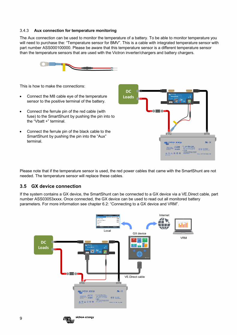
3.4.3 Aux connection for temperature monitoring
The Aux connection can be used to monitor the temperature of a battery. To be able to monitor temperature you will need to purchase the: “Temperature sensor for BMV”. This is a cable with integrated temperature sensor with part number ASS000100000. Please be aware that this temperature sensor is a different temperature sensor than the temperature sensors that are used with the Victron inverter/chargers and battery chargers.
This is how to make the connections: • Connect the M8 cable eye of the temperature
sensor to the positive terminal of the battery. • Connect the ferrule pin of the red cable (with
fuse) to the SmartShunt by pushing the pin into to the “Vbatt +” terminal.
• Connect the ferrule pin of the black cable to the
SmartShunt by pushing the pin into the “Aux” terminal.
Please note that if the temperature sensor is used, the red power cables that came with the SmartShunt are not needed. The temperature sensor will replace these cables. 3.5 GX device connection If the system contains a GX device, the SmartShunt can be connected to a GX device via a VE.Direct cable, part number ASS03053xxxx. Once connected, the GX device can be used to read out all monitored battery parameters. For more information see chapter 6.2: “Connecting to a GX device and VRM”.
DCLoads
VE.Direct cable
GX device
DCLoads
VRM
Local
Internet

10
4 COMMISSIONING Once the electrical connections have been made, the SmartShunt needs to be set up. This is done with the VictronConnect App. This App is needed to set up and to read out the SmartShunt.
4.1 Download and install VictronConnect To be able to communicate and set up the SmartShunt you will need to use the VictronConnect App. VictronConnect is a free App and is available for Android, iOS, MacOS or Windows. It can be downloaded from the respective App stores. Or alternatively see the “Downloads” section on our website: https://www.victronenergy.com/support-and-downloads/software.
4.2 Place the fuse If not already done so earlier, place the fuse in Vbatt+ cable. The blue “Bluetooth” light should start blinking. 4.3 Connect to the SmartShunt Connect to the SmartShunt via VictronConnect. This is done via Bluetooth. It is also possible to connect to the SmartShunt via USB or via VRM (Victron Remote Monitoring). For more information on this see paragraph 6: “Interfacing”.
This is how to connect: • Open the VictronConnect App. • Look for the SmartShunt to appear in the device list. • Click on the SmartShunt. • Enter the default PIN code which is 000000. • When successfully connected the “Bluetooth” light stays on.
After entering the default PIN code VictronConnect will ask you to change the PIN code. This is to prevent unauthorizes connections in the future. It is recommended that you change the PIN code on first install. This can be done in the product info tab, see paragraph 7.5.4: “Changing PIN code”.
For more information about VictronConnect see the VictronConnect manual: https://www.victronenergy.com/live/victronconnect:start. 4.4 Update firmware On first connection, VictronConnect can ask you to update the firmware of the Bluetooth interface and/or of the SmartShunt. This should always be done on first install. Without up to date firmware settings cannot be changed and only monitoring is active. 4.5 Make essential settings The default settings of the SmartShunt are tailored for lead acid batteries (flooded, GEL or AGM batteries). Please note that in case of lithium batteries or batteries with different chemistries, several additional settings will have to be changed. First make the essential settings as described in this paragraph and then refer to the next paragraph for the special lithium settings. Alternatively contact your battery supplier and refer to paragraph 7.1: “Battery settings”.
To make settings, navigate to the settings menu by clicking the settings button, located at the top right-hand side of VictronConnect.

11
Most settings can be kept by default. But there are a few settings that need to be changed. These are:
• Battery capacity. • Charged voltage. • State of charge or start synchronised. • The functionality of the auxiliary input (if used).
Should you want to find out what all the other settings mean, see paragraph 7.1: “Battery settings”. 4.5.1 Set the battery capacity setting
This setting can be found in VictronConnect > Settings > Battery. The SmartShunt is by default set to 200Ah. Change this value to match your battery capacity. For more information about battery capacity see paragraph 7.1.1: “Battery capacity”. 4.5.2 Set the charged voltage setting This setting can be found in VictronConnect > Settings > Battery. The SmartShunt is by default set to 0.0V. The SmartShunt does not automatically detect the system voltage like the BMV does. You will need to set the “Charged voltage”.
These are the recommended “Charged voltage” values: Nominal battery voltage Recommended charged voltage
setting 12 V 13.2 V 24 V 26.4 V 36 V 39.6 V 48 V 52.8 V
For more information about the charged voltage setting see paragraph 7.1.2: “Charged voltage”. 4.5.3 State of charge settings
This setting can be found in VictronConnect > Settings > Battery. When powered up for the first time, the SmartShunt will by default display 100% state of charge. If you want to change this to a different value, then it is possible to manually set the state of charge value. For more information see paragraph 7.1.10: “Battery starts synchronised” and paragraph 7.1.11: “State of charge”. 4.5.4 Set auxiliary input function
This setting can be found in VictronConnect > Settings > Misc.

12
This setting sets the function of the auxiliary input, being:
• Starter battery - Voltage monitoring of a second battery. • Midpoint - Measuring the midpoint of a battery bank. • Temperature - Measuring battery temperature via optional temperature sensor.
4.6 Make Lithium settings (if needed) LiFePO4 (Lithium Iron Phosphate or LFP) is the most used Li-ion battery chemistry. The factory defaults are in general also applicable to LFP batteries with exception of these settings:
• Charge efficiency. • Peukert exponent. • Tail current. Charge efficiency The charge efficiency of lithium batteries is much higher than that of lead acid batteries. We recommend setting the charge efficiency at 99%. For more information see paragraph 7.1.7: “Charge efficiency factor”. Peukert exponent When subjected to high discharge rates, lithium batteries perform much better than lead-acid batteries. Set the Peukert exponent at 1.05, unless the battery supplier advises otherwise. Tail current Some lithium battery chargers stop charging when the current drops below a set threshold. The tail current must be set higher in this case. Discharge floor This setting is used in “the time to go” calculation and is set at 50% by default. But lithium batteries usually can be discharge significantly deeper than 50%. The discharge floor can be set to a value between 10 and 20%, unless the battery supplier advises otherwise. Important warning Lithium batteries are expensive and can be irreparably damaged due to very deep discharge or overcharge. Damage due to deep discharge can occur if small loads slowly discharge the battery when the system is not in use. Some examples of these loads are alarm systems, standby currents of DC loads and back current drain of battery chargers or charge regulators. A residual discharge current is especially dangerous if the system has been discharged all the way until a low cell voltage shutdown has occurred. At this moment the state of charge can be as low as 1%. The lithium battery will get damaged if any remaining current is drawn from the battery. This damage can be irreversible.
A residual current of 1mA for example can damage a 100Ah battery if the battery has been left in discharged state during more than 40 days (1mA x 24h x 40 days = 0.96Ah). The SmartShunt draws <1mA from a 12V battery. The positive supply must therefore be interrupted if a system with Li-ion batteries is left unattended during a period long enough for the current draw by the SmartShunt to completely discharge the battery.
In case of any doubt about possible residual current draw, isolate the battery by opening the battery switch, by pulling the battery fuse(s) or by disconnecting the battery positive when the system is not in use.

13
5 OPERATION 5.1 How does the SmartShunt work? The main function of the SmartShunt is to follow and indicate the state of charge of a battery, to be able to know how much charge the battery contains and to prevent an unexpected total discharge. The SmartShunt continuously measures the current flow in and out of the battery. Integration of this current over time, if it was a fixed current, boils down to multiplying current and time and gives the net amount of Ah added or removed. For example: a discharge current of 10A for 2 hours will take 10 x 2 = 20Ah from the battery. To complicate matters, the effective capacity of a battery depends on the rate of discharge, the Peukert efficiency, and, to a lesser extent, the temperature. And to make things even more complicated: when charging a battery more energy (Ah) has to be ‘pumped’ into the battery than can be retrieved during the next discharge. In other words: the charge efficiency is less than 100%. The SmartShunt takes all these factors in consideration when calculating the state of charge. 5.2 Readout overview The status screen of the SmartShunt displays an overview of important parameters:
• State of charge. • Battery voltage. • Battery current. • Power. • Aux input reading (starter battery, midpoint or temperature). State of charge This is the actual state of charge of the battery in percent and is compensated for both the Peukert efficiency and charge efficiency. The state of charge is the best way to monitor the battery. A fully charged battery will be indicated by a value of 100.0%. A fully discharged battery will be indicated by a value of 0.0%. Please note that if the state of charge indicates three dashes: “---” this means that the SmartShunt is in an unsynchronised state. This mainly occurs when the SmartShunt has just been installed or after the SmartShunt has been left unpowered and is powered up again. For more information, see paragraph 5.3: “Synchronising the SmartShunt”. Voltage This is the terminal voltage of the battery. Current This is the actual current flowing in or out of the battery. A negative current indicates that current is taken from the battery. This is the current needed for DC loads. A positive current means that current is going into the battery. This is current coming from charge sources. Keep in mind that the SmartShunt will always indicate the total battery current, being the current traveling into the battery minus the current traveling out of the battery. Power The power drawn from or received by the battery. Consumed Ah The SmartShunt keeps track of the Amp-hours removed from the battery compensated for the efficiency. Example: If a current of 12A is drawn from a fully charged battery for a period of 3 hours, the readout will show -36.0Ah (-12 x 3 = -36). Please note that if the Consumed Ah indicates three dashes: “---” this means that the SmartShunt is in an unsynchronised state. This mainly occurs when the SmartShunt has just been installed or after the SmartShunt been left unpowered and is powered up again. For more information, see paragraph 5.3: “Synchronising the SmartShunt”.

14
Time remaining The SmartShunt estimates how long the battery can support the present load. This is the “time-to-go” readout and is the actual time left until the battery is discharged to the set “discharge floor”. The discharge floor is by default set at 50%. For the discharge floor setting see paragraph 7.1.3: “Discharge floor”. If the load is fluctuating heavily, it is best not to rely on this reading too much, as it is a momentary readout and should be used as a guideline only. We recommend the use of the state of charge readout for accurate battery monitoring. If the “Time remaining” indicates three dashes: “---” this means that the SmartShunt is in an unsynchronised state. This occurs when the SmartShunt has just been installed or after the SmartShunt has been left unpowered and is powered up again. For more information, see paragraph 5.3: “Synchronising the SmartShunt”. Input This is the state of the Aux input. Depending on how the Aux port has been set up, you will see one of these options:
• Starter battery voltage: This shows the voltage of a second battery. • Battery temperature: This shows the battery temperature of the main battery when the optional temperature
sensor is used. • Midpoint voltage deviation: This shows the deviation in a percentage of the main voltage of the battery
bank top section compared to the voltage of the bottom section. For more information on this feature see chapter 9: “Midpoint voltage monitoring”.
5.3 Synchronising the SmartShunt For a reliable readout, the state of charge, as displayed by the battery monitor, must be synchronised regularly with the true state of charge of the battery. This to prevent drift of the “State of charge” value over time. A synchronisation will reset the state of charge of the battery to 100%.
5.3.1 Automatic synchronisation
Synchronisation is an automatic process and will occur when the battery has been fully charged. The SmartShunt will look at a few parameters to ascertain that the battery has been fully charged. It will consider the battery to be fully charged when the voltage has reached a certain value and the current has dropped below a certain value for a certain amount of time.
These parameters are called:
• Charged voltage - the float voltage of battery charger. • Tail current - a percentage of the battery capacity. • Charged detection time - the time in minutes.
As soon as these 3 parameters have been met, the SmartShunt will set the state of charge value to 100%, thus synchronising the state of charge.
Example: In case of a 12V battery, the SmartShunt will reset the battery’s state of charge to 100% when all these parameters have been met:
• The voltage exceeds 13.2V, • the charge current is less than 4.0% of the total battery capacity (e.g. 8A for a 200Ah battery) and, • 3 minutes have passed while both the voltage and current conditions are met. If the SmartShunt does not perform a regular synchronisation, the state of charge value will start to drift over time. This is due to the small inaccuracies of the SmartShunt and because of the estimation of the Peukert exponent. Once a battery has been fully charged, and the charger has gone to float stage, the battery is full and the SmartShunt will automatically synchronise by setting the state of charge value to 100%.

15
5.3.2 Manual synchronisation
The SmartShunt can be synchronised manually if required. This can be achieved by pressing the synchronise button in the VictronConnect battery settings. A manual synchronisation can be needed in situations when the SmartShunt does not synchronise automatically. This is for example needed on first install or after the voltage supply to the SmartShunt has been interrupted. A manual synchronisation can also be needed when the battery has not been fully charged, or if the SmartShunt has not detected that the battery has been fully charged because the charged voltage, current or time have been set incorrectly. In this case review the settings and make sure the battery regularly receives a full charge. 5.4 Alarms The SmartShunt can raise an alarm on low state of charge, low or high battery voltages readings, low or high temperature readings or a certain midpoint deviation. The alarm will activate when the value reaches a set threshold and will deactivate once when the value clears this threshold.
The alarm is a software alarm. When connecting with the VictronConnect App and an alarm is active, the alarm will show in the App. Or, alternatively, when the SmartShunt is connected to a GX device the alarm will show up on the GX device or on VRM.
In case of VictronConnect an alarm is acknowledged when a button is pressed. And in a GX device an alarm is acknowledged when viewed in notifications. However, the alarm icon is displayed as long as the alarm condition remains.
Please note that unlike the BMV battery monitor range, the SmartShunt does not have an alarm relay or buzzer. In case a relay function is needed, connect the SmartShunt to a GX device and use the relay in the GX device with SmartShunt functionality.
5.5 History data The SmartShunt stores historic events. These can be used at a later date to evaluate usage patterns and battery health. The history can be accessed in the “History” tab in VictronConnect. The history data is stored in a non-volatile memory and will not be lost when the power supply to the SmartShunt has been interrupted or when the SmartShunt has been reset to its defaults.
Discharge information in Ah • Deepest discharge: The SmartShunt remembers the deepest discharge and each
time the battery is discharged deeper the old value will be overwritten. • Last discharge: The SmartShunt keeps track of the discharge during the current
cycle and displays the largest value recorded for Ah consumed since the last synchronisation.
• Average discharge: The cumulative Ah drawn divided by the total number of cycles.
• Cumulative Ah drawn - The cumulative number of Amp hours drawn from the battery over the lifetime of the SmartShunt.
Energy in kWh • Discharged energy: This is the total amount of energy drawn from the battery in
(k)Wh. • Charged energy: The total amount of energy absorbed by the battery in (k)Wh.
Charge • Total charge cycles: The number of charge cycles over the lifetime of the SmartShunt. A charge cycle is
counted every time the state of charge drops below 65% and then rises above 90%.

16
• Time since last full charge: The number of days since the last full charge. • Synchronisations: The number of automatic synchronisations. A synchronisation is counted every time the
state of charge drops below 90% before a synchronisation occurs. • Number of full discharges: The number of full discharges. A full discharge is counted when the state of
charge reaches 0%.
Battery voltage • Min battery voltage: The lowest battery voltage. • Max battery voltage: The highest battery voltage. • Min starter voltage: The lowest auxiliary battery voltage (if applicable). • Max starter voltage: The highest auxiliary battery voltage (if applicable).
Voltage alarms • Low voltage alarms: The number of low voltage alarms. • High voltage alarms: The number of high voltage alarms. 5.6 Trends The “Trends” section of VictronConnect enables datalogging, but only while VictronConnect is connected and communicating with the SmartShunt. It will simultaneously log two of the following parameters: voltage, current, power consumed Ah or state of charge.
5.7 LED status codes The SmartShunt has two LEDs, a Bluetooth status LED (blue), and an error LED (red). These LEDs are both associated with the SmartShunt Bluetooth interface.
• On power-up, the blue LED will blink, and the red LED will quickly flash. The red LED will give a short flash to confirm that the red LED is functional.
• When the blue LED is blinking the SmartShunt is ready to be connected to VictronConnect.
• When the blue LED is stays on, the SmartShunt has successfully connected to VictronConnect via Bluetooth.
• When the blue and the red LEDs are alternating blinking the SmartShunt firmware is being updated.

17
6 INTERFACING The SmartShunt can be connected to other equipment, this chapter describes how this can be done. 6.1 VictronConnect via USB VictronConnect can not only connect via Bluetooth but it can also connect via USB. A USB connection is essential when connecting to the Windows version of VictronConnect and is optional when the MacOS or Android version us used. Please note that in case of connecting to an Android phone or tablet a “USB on the Go” cable might be needed.
To connect via USB, you will need a “VE.Direct to USB interface”, part number SS030530000. Use this interface to connect the computer to the SmartShunt. For more information see the VictronConnect manual: https://www.victronenergy.com/live/victronconnect:start. 6.2 Connecting to a GX device and VRM GX devices are Victron devices that provide control and monitoring for all Victron equipment products connected to it. Control and monitoring can be done locally but can also be done remotely via our free remote monitoring website “Victron Remote Monitoring”, the VRM online portal. For an overview of all available GX devices, see: https://www.victronenergy.com.au/panel-systems-remote-monitoring. For a link to the VRM website, see: https://vrm.victronenergy.com
The SmartShunt can be connected to a GX device with a VE.Direct cable, part number ASS03053xxxx. The VE.Direct cables are available in lengths ranging from 0.3 to 10 meters and are available with straight or right-angle connectors. Instead of using a VE.Direct cable, the SmartShunt can also connect to GX device using the VE.Direct to USB interface.
Once connected, the GX device can be used to read out all monitored battery parameters.
DCLoads
VE.Direct to USB interface
Laptop
VE.Direct cable
GX device
DCLoads
VRM
Local
Internet

18
6.3 Connecting to VE.Smart network The VE.Smart Network is a wireless network which allows a number of Victron products to exchange information via Bluetooth. The SmartShunt can share battery voltage and temperature (optional temperature sensor needed) with the VE.Smart network.
For example: A VE.Smart network containing a SmartSolar with temperature sensor and a MPPT solar charger, the solar charger receives the battery voltage and temperature information from the SmartShunt and uses this information to optimise its charge parameters. This will improve charging-efficiency and prolong battery life.
To make the SmartShunt part of a VE.Smart network, you will have to either create a network or join an existing network. The setting can be found in SmartShunt settings >smart networking. Please see the VE.Smart network manual for more information: https://www.victronenergy.com/live/victronconnect:ve-smart-networking
6.4 Custom integration (programming required) The VE.Direct communications port can be used to read data and change settings. The VE.Direct protocol is extremely simple to implement. Transmitting data to the SmartShunt is not necessary for simple applications: the SmartShunt automatically sends all readings every second.
All the details are explained in this document: https://www.victronenergy.com/upload/documents/Whitepaper-Data-communication-with-Victron-Energy-products_EN.pdf
DCLoads
Solar panelSmart MPPT
charge controller
Temperature sensor for BMV

19
7 ALL FEATURES AND SETTINGS 7.1 Battery settings These settings can be used to fine-tune the SmartShunt. Please be careful when you change these settings as a change will have an effect on the SmartShunt state of charge calculations. 7.1.1 Battery capacity
This parameter is used to tell the SmartShunt how big the battery is. This setting should already have been done during the initially installation of the SmartShunt. The setting is the battery capacity in Amp hours (Ah). For more information see chapter 8: “Battery capacity and Peukert exponent”. Default setting Range Step size 200Ah 1 – 9999Ah 1Ah
7.1.2 Charged voltage
The battery voltage must be above this voltage level to consider the battery as fully charged. As soon as the SmartShunt detects that the voltage of the battery has reached the “charged voltage” and the current has dropped below the “tail current” for a certain amount of time, the SmartShunt will set the state of charge to 100%. Default setting Range Step size 0V 0 - 95V 0.1V
The “charged voltage” parameter should be set to 0.2V or 0.3V below the float voltage of the charger. Or alternatively, see the table below for the recommended setting.
Recommended settings for lead acid batteries: Nominal battery voltage charged voltage setting 12V 13.2V 24V 26.4V 36V 39.6V 48V 52.8V
7.1.3 Discharge floor
The “Discharge floor” parameter is used in the time remaining calculation. The time remaining is the time it takes until the set “Discharge floor” has been reached. Default setting Range Step size 50% 0 - 99% 1%
7.1.4 Tail current
The battery is considered as “fully charged” once the charge current has dropped to less than the set “Tail current” parameter. The “Tail current” parameter is expressed as a percentage of the battery capacity. Remark: Some battery chargers stop charging when the current drops below a set threshold. In these cases, the tail current must be set higher than this threshold. As soon as the SmartShunt detects that the voltage of the battery has reached the set “Charged voltage” parameter and the current has dropped below the “Tail current” for a certain amount of time, the SmartShunt will set the state of charge to 100%. Default setting Range Step size 4.00% 0.50 – 10.00% 0.1%

20
7.1.5 Charged detection time
This is the time the “Charged voltage” and “Tail current” must be met in order to consider the battery fully charged.
Default setting Range Step size 3 minutes 0 – 100 minutes 1 minute
7.1.6 Peukert exponent
When unknown it is recommended to keep this value at 1.25 (default) for lead acid batteries and change to 1.05 for Li-ion batteries. A value of 1.00 disables the Peukert compensation. For more information see chapter 8: “Battery capacity and Peukert exponent”
Default setting Range Step size 1.25 1.00 – 1.50 0.01
7.1.7 Charge efficiency factor
The “Charge Efficiency Factor” compensates for the capacity (Ah) losses during charging. A setting of 100% means that there are no losses.
Default setting Range Step size 95% 50 – 100% 1%
The charge efficiency of a lead acid battery is almost 100% as long as no gas generation takes place. Gassing means that part of the charge current is not transformed into chemical energy, which is stored in the plates of the battery, but is used to decompose water into oxygen and hydrogen gas (highly explosive!). The energy stored in the plates can be retrieved during the next discharge, whereas the energy used to decompose water is lost. Gassing can easily be observed in flooded batteries. Please note that the ‘oxygen only’ end of the charge phase of sealed (VRLA) gel and AGM batteries also results in a reduced charge efficiency. A charge efficiency of 95% means that 10Ah must be transferred to the battery to get 9.5Ah actually stored in the battery. The charge efficiency of a battery depends on battery type, age and usage. The SmartShunt takes this phenomenon into account with the charge efficiency factor. 7.1.8 Current threshold
When the current measured falls below the “Current threshold” value it will be considered zero. The “Current threshold” is used to cancel out very small currents that can negatively affect the long-term state of charge readout in noisy environments. For example, if the actual long-term current is 0.0A and, due to injected noise or small offsets, the battery monitor measures -0.05A the SmartShunt might, in the long term, incorrectly indicate that the battery is empty or will need to be recharged. When the current threshold in this example is set to 0.1A, the SmartShunt calculates with 0.0A so that errors are eliminated. A value of 0.0A disables this function.
Default setting Range Step size 0.10A 0.00 – 2.00A 0.01A
7.1.9 Time-to-go averaging period
The time-to-go averaging period specifies the time window (in minutes) that the moving averaging filter works. A value of 0 disables the filter and gives an instantaneous (real-time) readout. However, the displayed “Time remaining” value may fluctuate heavily. Selecting the longest time, 12 minutes, will ensure that only long-term load fluctuations are included in the “Time remaining” calculations.
Default setting Range Step size 3 minutes 0 – 12 minutes 1 minute

21
7.1.10 Battery starts synchronised
The battery state of charge will become 100% after the SmartShunt is powered up. When ON, the SmartShunt will consider itself synchronised when powered-up, resulting in a state of charge of 100%. If set to OFF, the SmartShunt will consider it unsynchronised when powered-up, resulting in a state of charge that is unknown until the first actual synchronisation. Default setting Range ON ON/OFF
Please be aware that situations can occur where special consideration is needed when setting this feature to ON. One of these situations occurs in systems where the battery is often disconnected from the SmartShunt, for example on a boat. If you leave the boat and disconnect the DC system via the main DC breaker and at that moment the batteries were, for example, 75% charged. On return to the boat the DC system is reconnected and the SmartShunt will now indicate 100%. This will give a false impression that the batteries are full, while in reality they are partially discharged. There are two ways of solving this, one is to not disconnect the SmartShunt when the batteries are partially discharged or alternatively turn the “Battery starts synchronised” feature off. Now when the SmartShunt is reconnected the state of charge will display “---” and will not show 100% until the batteries have been fully charged. Please note that leaving a lead acid battery in a partially discharged state for a length of time will cause battery damage. 7.1.11 State of charge
With this setting you can manually set the state of charge value. This setting is only active after the SmartShunt has, at least once, been synchronised. Either automatically or manually. Default setting Range Step size --% 0.0 - 100% 0.1%
7.1.12 Synchronise SoC to 100%
This option can be used to manually synchronise the SmartShunt. Press the ”Synchronise” button to synchronise the SmartShunt to 100%. For more information, see paragraph 5.3.2: “Manual synchronisation”. 7.1.13 Zero current calibration
If the SmartShunt reads a non-zero current even when there is no load and the battery is not being charged, this option can be used to calibrate the zero reading. Ensure that there really is no current flowing into or out of the battery. Do this by disconnecting the cable between the load and the SmartShunt and press the “calibrate button” to perform a zero-current calibration. 7.2 Alarm settings Please note that the SmartShunt is not equipped with a buzzer or an alarm relay like the BMV series is. The generated alarms are only visible on the VictronConnect App while connected to the SmartShunt or are used to send an alarm signal to a GX device.

22
7.2.1 SoC alarm setting
When enabled, the alarm will activate when the state of charge falls below the set value for more than 10 seconds. The alarm will deactivate when the state of charge rises above the clear value
Default setting Range Disabled Disabled /
enabled
When enabled Default setting Set value 1% 0 – 100% 1% Clear value 2% 0 – 100% 1%
7.2.2 Low voltage alarm
When enabled, the alarm will activate when battery voltage falls below the set value for more than 10 seconds. The alarm will deactivate when the battery voltage rises above the clear value.
Default setting Range Disabled Disabled /
Enabled
When enabled Default setting Set value 1.0V 0 - 95.0V 0.1V Clear value 1.1V 0 - 95.0V 0.1V
7.2.3 High voltage alarm
When enabled, the alarm will activate when battery voltage rises above the set value for more than 10 seconds. The alarm will deactivate when the battery voltage drops below the clear value.
Default setting Range Disabled Disabled /
enabled
When enabled Default setting Set value 1.1V 0 - 95.0V 0.1V Clear value 1.0V 0 - 95.0V 0.1V
7.2.4 Low starter voltage alarm
This setting is only available if the Aux input has been set to “Starter battery”. When enabled, the alarm will activate when starter battery voltage falls below the set value for more than 10 seconds. The alarm will deactivate when the starter battery voltage rises above the clear value.
Default setting Range Disabled Disabled /
Enabled
When enabled Default setting Set value 1.0V 0 - 95.0V 0.1V Clear value 1.1V 0 - 95.0V 0.1V

23
7.2.5 High starter voltage alarm
This setting is only available if the Aux input has been set to “Starter battery”. When enabled, the alarm will activate when starter battery voltage rises above the set value for more than 10 seconds. The alarm will deactivate when the starter battery voltage drops below the clear value. Default setting Range Disabled Disabled /
enabled When enabled Default setting Set value 1.1V 0 - 95.0V 0.1V Clear value 1.0V 0 - 95.0V 0.1V
7.2.6 Midpoint deviation alarm
This setting is only available if the Aux input has been set to “Midpoint”. When enabled, the alarm will activate when the midpoint voltage deviation rises above the set value for more than 10 seconds. The alarm will deactivate when the midpoint voltage deviation drops below the clear value. Default setting Range Disabled Disabled /
enabled When enabled Default setting Set value 2% 0 – 99% 1% Clear value 1% 0 – 99% 1%
7.2.7 High temperature alarm
This setting is only available if the Aux input has been set to “Temperature”. When enabled, the alarm will activate when the battery temperature rises above the set value for more than 10 seconds. The alarm will deactivate when the battery temperature drops below the clear value. Default setting Range Disabled Disabled /
enabled When enabled Default
setting Range Step size
Set value 2°C (2°F) -99 - +99°C (-146 - +210°F)
1°C (1°F)
Clear value 1°C (2°F) -99 - +99°C (-146 - +210°F)
1°C (1°F)
7.2.8 Low temperature alarm
This setting is only available if the Aux input has been set to “Temperature”. When enabled, the alarm will activate when the battery temperature falls below the set value for more than 10 seconds. The alarm will deactivate when the battery temperature rises above the clear value. Default setting Range Disabled Disabled /
enabled

24
When enabled Default
setting Range Step size
Set value 2°C (2°F) -99 - +99°C (-146 - +210°F)
1°C (1°F)
Clear value 1°C (2°F) -99 - +99°C (-146 - +210°F)
1°C (1°F)
7.3 Miscellaneous settings 7.3.1 Aux input
This setting sets the function of the auxiliary input. Select between: Starter battery, Midpoint or Temperature
Default setting Range Starter battery Starter battery / Midpoint /
Temperature 7.3.2 Temperature coefficient
This setting is only available after the Aux input setting has been set to “Temperature”.
The available battery capacity decreases with temperature. Typically, the reduction, compared to the capacity at 20°C, is 18% at 0°C and 40% at -20°C.
The temperature coefficient is the percentage the battery capacity changes with temperature when temperature decreases to less than 20°C (above 20°C the influence of temperature on capacity is relatively low and is not taken into account). The unit of this value is “%cap/°C” or percent capacity per degree Celsius. The typical value (below 20°C) is 1%cap/°C for lead acid batteries, and 0.5%cap/°C for LFP batteries.
Default setting Range Step size 0.0%cap/°C 0.0%cap/°F
0 - 2.0%cap/°C 0 - 3.6%cap/°F
0.1%cap/°C 0.1%cap/°F
7.4 Temperature unit setting This setting can be found in the settings of the VictronConnect App itself. Leave the SmartShunt by clicking on the ← arrow. This will bring you back to the device list of the VictronConnect App. Click on the menu symbol and then click on the settings symbol. Here you can select the “Display temperature unit”. Selecting Celsius will display the temperature in °C and selecting Fahrenheit will display the temperature in °F.
Default setting Range Celsius Celsius / Fahrenheit
7.5 Product settings To access these settings, click on the setting symbol and then on the menu symbol . 7.5.1 Reset to defaults
To set all settings back to default select “Reset to defaults”. Please note that this only resets all settings to their default values, the history is not reset. 7.5.2 Custom name
In the SmartShunt product information screen, you can change the name of the SmartShunt. By default, it is called by its product name. But a more applicable name might be needed, especially if you are using multiple SmartShunts in close proximity of each other it might become confusing with which SmartShunt you are communicating. You can, for example, add identification numbers to their name, like: SmartShunt A, SmartShunt B and so on.

25
7.5.3 Firmware
Both the SmartShunt and its Bluetooth interface run on firmware. Occasionally a newer firmware version is available. New firmware is released to either add features or to fix a bug. The Product overview of both the SmartShunt and its Bluetooth interface items both display the firmware number. It also indicates whether the firmware the latest version and there is a button you can press to update the firmware. On first install it is always recommended to update to the most recent firmware (if available). Whenever you connect to the SmartShunt with a “up to date” version of VictronConnect, it will check firmware and it will ask you to update firmware if there is a newer version available. VictronConnect includes the actual firmware files, so an internet connection is not needed to update to the most recent firmware, as long as you are using the most up to date version of VictronConnect. A firmware update is not mandatory. If you choose not to update the firmware, you can only read out the SmartShunt, but you cannot change settings. Settings can only be changed if the SmartShunt runs on the most recent firmware. 7.5.4 Changing PIN code
In the SmartShunt Bluetooth interface product info the PIN code can be changed. 7.5.5 Disabling and re-enabling Bluetooth
Bluetooth is enabled by default in the SmartShunt. If Bluetooth is not wanted it can be disabled. This is done by sliding the Bluetooth switch in the product settings.
A reason to disable Bluetooth could be for security reasons, or to eliminate unwanted transmission from the SmartShunt.
As soon as Bluetooth has been disabled the only way to communicate with the SmartShunt is via its VE.Direct port.
This is done via the USB to VE.Direct interface or via a GX device connected to the SmartShunt via a VE.Direct cable or the USB to VE.Direct interface. For more info see chapter 6: “Interfacing”.
Bluetooth can be re-enabled by connecting to the SmartShunt with VictronConnect via the VE.Direct – USB interface. Once connected you can navigate to the product settings menu and re-enable Bluetooth.
7.5.6 Serial number
The serial number can be found in the SmartShunt product info or on the product information sticker on the SmartShunt. 7.6 Saving, loading and sharing settings In the settings menu you can find the following 3 symbols:
Save settings to file - This will save settings for reference or for later use.
Load settings from file – This will load earlier saved settings.
Share settings file – This allows you to share the settings file via email, message, airdrop and so on. The available sharing options depend on the platform used. For more information on these features, see the VictronConnect manual: https://www.victronenergy.com/live/victronconnect:start

26
7.7 Reset history This setting can be found at to bottom of the history tab. Please be aware that history data is an important tool to keep track of battery performance and is also needed to diagnose possible battery problems. Do not clear the history unless the battery bank is replaced.
7.8 Reset PIN code This setting can be found in the settings of the VictronConnect App itself. Leave the SmartShunt by clicking on the ← arrow. This will bring you back to the device list of the VictronConnect App. Now, click on the menu symbol next to the SmartShunt listing. A new window will open which allows you to reset the PIN code back to its default: 000000. To be able to reset the PIN code you will need the enter the SmartShunt unique PUK code. The PUK code is printed on the product information sticker on the SmartShunt.

27
8 BATTERY CAPACITY AND PEUKERT EXPONENT Battery capacity is expressed in Amp hour (Ah) and indicates how much current a battery can supply over time. For example, if a 100Ah battery is being discharged with a constant current of 5A, the battery will be totally discharged in 20 hours. The rate at which a battery is being discharged is expressed as the C rating. The C rating indicates how many hours a battery with a given capacity will last. 1C is the 1h rate and means that the discharge current will discharge the entire battery in 1 hour. For a battery with a capacity of 100Ah, this equates to a discharge current of 100A. A 5C rate for this battery would be 500A for 12 minutes (1/5 hours), and a C5 rate would be 20A for 5 hours. The capacity of a battery depends on the rate of discharge. The faster the rate of discharge, the less capacity will be available. The relation between slow or fast discharge can be calculated by Peukert’s law and is expressed by the Peukert exponent. Some battery chemistries suffer more from this phenomenon than others. Lead acid are more affected by this than lithium batteries are. The SmartShunt takes this phenomenon into account with Peukert exponent.
Discharge rate example A lead acid battery is rated at 100Ah at C20, this means that this battery can deliver a total current of 100A over 20 hours at a rate of 5A per hour. C20 = 100Ah (5 x 20 = 100). When the same 100Ah battery is discharged completely in two hours, its capacity is greatly reduced. Because of the higher rate of discharge, it may only give C2 = 56Ah. Peukert’s formula The value which can be adjusted in Peukert’s formula is the exponent n: see the formula below. In the SmartShunt the Peukert exponent can be adjusted from 1.00 to 1.50. The higher the Peukert exponent the faster the effective capacity ‘shrinks’ with increasing discharge rate. An ideal (theoretical) battery has a Peukert exponent of 1.00 and has a fixed capacity regardless of the size of the discharge current. The default setting in the SmartShunt for the Peukert exponent is 1.25. This is an acceptable average value for most lead acid batteries. Peukert’s equation is stated below: 𝐶𝐶𝐶𝐶 = 𝐼𝐼𝑛𝑛 × 𝑡𝑡 where Peukert’s exponent n is: 𝑛𝑛 = log 𝑡𝑡2−log 𝑡𝑡1
log 𝐼𝐼1−log 𝐼𝐼2
To calculate the Peukert exponent you will need two rated battery capacities. This is usually the 20h discharge rate and the 5h rate, but can also be the 10h and 5h, or the 20h and the 10h rate. Ideally use a low discharge rating together with a substantially higher rating. Battery capacity ratings can be found in the battery datasheet. If in doubt contact your battery supplier. Calculation example using the 5h and the 20h rating The C5 rating is 75Ah. The t1 rating is 5h and I1 is calculated: 𝐼𝐼1 = 75𝐴𝐴ℎ
5ℎ= 25𝐴𝐴
The C20 rating is 100Ah. The t2 rating is 20h and I2 is calculated: 𝐼𝐼2 = 100𝐴𝐴ℎ20ℎ
= 5𝐴𝐴 The Peukert exponent is: 𝑛𝑛 = log 20−log 5
log 15−log 5 = 1.26 A Peukert calculator is available at http://www.victronenergy.com/support-and-downloadssoftware/ Please note that the Peukert exponent is no more than a rough approximation of reality, and that at very high currents, batteries will give even less capacity than predicted from a fixed exponent. We recommend not to change the default value in the SmartShunt, except in case of lithium batteries.

28
9 MIDPOINT VOLTAGE MONITORING One bad cell or one bad battery can destroy a large, expensive battery bank. A short circuit or high internal leakage current in one cell for example will result in undercharge of that cell and overcharge of the other cells. Similarly, one bad battery in a 24V or 48V bank of several series/parallel connected 12V batteries can destroy the whole bank. Moreover, when new cells or batteries are connected in series, they should all have the same initial state of charge. Small differences will be ironed out during absorption or equalize charging, but large differences will result in damage during charging due to excessive gassing of the cells or batteries with the highest initial state of charge. A timely alarm can be generated by monitoring the midpoint of the battery bank (i.e. by splitting the string voltage in half and comparing the two string voltage halves). The midpoint deviation will be small when the battery bank is at rest, and will increase:
• At the end of the bulk phase during charging (the voltage of well charged cells will increase rapidly while lagging cells still need more charging).
• When discharging the battery bank until the voltage of the weakest cells starts to decrease rapidly. • At high charge and discharge rates. 9.1 Battery bank and midpoint wiring diagrams 9.1.1 Connecting and monitoring midpoint in a 24V battery bank
Due to the voltage drop over the positive and the negative cables the midpoint voltage are not identical.
In an unmonitored battery bank the midpoints should not be interconnected, one bad battery bank can go
unnoticed and could damage all other batteries. Always use busbars when applying midpoint voltage monitoring. The cables to the busbars must all have the same length.
Midpoints can only be connected if corrective action is taken in case of an alarm.
OK
GOOD
WRONG
SHUNT
Vbatt+ Aux

29
9.1.2 Connecting and monitoring midpoint in a 48V battery bank
Due to the voltage drop over the positive and the negative cables the midpoint voltage are not identical.
In an unmonitored battery bank the midpoints should not be interconnected, one bad battery bank can go unnoticed and could damage all other batteries. Always use busbars when applying midpoint voltage monitoring. The cables to the busbars must all have the same length.
Midpoints can only be connected if corrective action is taken in case of an alarm. 9.2 Midpoint deviation calculation The SmartShunt measures the midpoint and then calculates the deviation in a percentage from what the midpoint should be.
𝐷𝐷𝐷𝐷𝐷𝐷𝐷𝐷𝐷𝐷𝑡𝑡𝐷𝐷𝐷𝐷𝑛𝑛 = 100 × (𝑡𝑡𝐷𝐷𝐶𝐶 𝑠𝑠𝑡𝑡𝑠𝑠𝐷𝐷𝑛𝑛𝑠𝑠 𝐷𝐷𝐷𝐷𝑣𝑣𝑡𝑡𝐷𝐷𝑠𝑠𝐷𝐷 – 𝑏𝑏𝐷𝐷𝑡𝑡𝑡𝑡𝐷𝐷𝑏𝑏 𝑠𝑠𝑡𝑡𝑠𝑠𝐷𝐷𝑛𝑛𝑠𝑠 𝐷𝐷𝐷𝐷𝑣𝑣𝑡𝑡𝐷𝐷𝑠𝑠𝐷𝐷)
𝑏𝑏𝐷𝐷𝑡𝑡𝑡𝑡𝐷𝐷𝑠𝑠𝑏𝑏 𝐷𝐷𝐷𝐷𝑣𝑣𝑡𝑡𝐷𝐷𝑠𝑠𝐷𝐷
𝑑𝑑 = 100 × (𝑉𝑉𝑡𝑡 – 𝑉𝑉𝑏𝑏)
𝑉𝑉
OK WRONG
GOOD
Vbatt+ Aux
SHUNT

30
where:
d is the deviation in % Vt is the top string voltage Vb is the bottom string voltage V is the voltage of the battery (V = Vt + Vb) 9.3 Setting the alarm level In case of VRLA (gel or AGM) batteries, gassing due to overcharging will dry out the electrolyte, increasing internal resistance and ultimately resulting in irreversible damage. Flat plate VRLA batteries start to lose water when the charge voltage approaches 15V (12V battery). Including a safety margin, the midpoint deviation should therefore remain below 2% during charging. When, for example, charging a 24V battery bank at 28.8V absorption voltage, a midpoint deviation of 2% would result in:
𝑉𝑉𝑡𝑡 = 𝑉𝑉 × 𝑑𝑑100 + 𝑉𝑉𝑏𝑏 =
𝑉𝑉 × 𝑑𝑑100 + 𝑉𝑉 − 𝑉𝑉𝑡𝑡 = 𝑉𝑉 ×
1 + 𝑑𝑑100
2 Therefore:
𝑉𝑉𝑡𝑡 = 𝑉𝑉 ×1 + 𝑑𝑑
1002 𝐷𝐷𝑛𝑛𝑑𝑑 𝑉𝑉𝑏𝑏 = 𝑉𝑉 ×
1− 𝑑𝑑100
2
𝑉𝑉𝑡𝑡 = 28.8 ×1 + 2
1002 ≈ 14.7 𝐷𝐷𝑛𝑛𝑑𝑑 𝑉𝑉𝑏𝑏 = 28.8 ×
1 − 2100
2 ≈ 14.1 Obviously, a midpoint deviation of more than 2% will result in overcharging the top battery and undercharging the bottom battery. These are two good reasons to set the midpoint alarm level at not more than d = 2%. This same percentage can be applied to a 12V battery bank with a 6V midpoint. In case of a 48V battery bank consisting of 12V series connected batteries, the % influence of one battery on the midpoint is reduced by half. The midpoint alarm level can therefore be set at a lower level. 9.4 Alarm delay In order to prevent the occurrence of alarms due to short term deviations that will not damage a battery, the deviation must exceed the set value during 5 minutes before the alarm is triggered. A deviation exceeding the set value by a factor of two or more will trigger the alarm after 10 seconds. 9.5 What to do in case of an alarm during charging In case of a new battery bank The alarm is usually due to differences in the initial state of charge of the individual battery. If the deviation increases to more than 3% you should stop charging the battery bank and charge the individual batteries or cells separately. Another way is to substantially reduce the charge current to the battery bank, this will allow the batteries to equalize over time. If the problem persists after several charge-discharge cycles do the following:
• In case of series-parallel connection disconnect the midpoint, parallel connection wiring and measure the individual midpoint voltages during absorption charging to isolate batteries or cells which need additional charging.
• Charge and then test all batteries or cells individually.
Battery bank voltage
DCLoads
Midpoint
Top string voltage Bottom string voltage

31
In case of an older battery bank which has performed well in the past The problem may be due to systematic undercharge. In this case more frequent charging or an equalization charge is needed. Please note that only flooded deep cycle flat plate or OPzS batteries can be equalized. Better and regular charging will solve the problem. In case there are one or more faulty cells:
• In case of series-parallel connection disconnect the midpoint, parallel connection wiring and measure the individual midpoint voltages during absorption charging to isolate batteries or cells which need additional charging.
• Charge and then test all batteries or cells individually. 9.6 What to do in case of an alarm during discharging The individual batteries or cells of a battery bank are not identical, and when fully discharging a battery bank, the voltage of some cells will start dropping earlier than others. The midpoint alarm will therefore nearly always trip at the end of a deep discharge. If the midpoint alarm trips much earlier (and does not trip during charging), some batteries or cells may have lost capacity or may have developed a higher internal resistance than others. The battery bank may have reached the end of service life, or one or more cells or batteries have developed a fault:
• In case of series-parallel connection, disconnect the midpoint parallel connection wiring and measure the individual midpoint voltages during discharging to isolate faulty batteries or cells.
• Charge and then test all batteries or cells individually. 9.7 The Battery Balancer A consideration can be made to add a Battery Balancer to the system. A Battery Balancer will equalize the state of charge of two series connected 12V batteries, or of several parallel strings of series connected batteries.
When the charge voltage of a 24V battery system increases to more than 27.3V, the Battery Balancer will turn on and compare the voltage over the two series connected batteries. The Battery Balancer will draw a current of up to 0.7A from the battery (or parallel connected batteries) with the highest voltage. The resulting charge current differential will ensure that all batteries will converge to the same state of charge. If needed, several balancers can be paralleled.
A 48V battery bank can be balanced with three Battery Balancers, one between each battery.
For more information see the Battery Balancer datasheet located on the Battery Balancer product page: https://www.victronenergy.com.au/batteries/battery-balancer
32
10 TROUBLESHOOTING 10.1 Functionality issues 10.1.1 Unit is dead, no lights on
On first connection the blue LED on the SmartShunt should be blinking. If this is not the case check the fuse in the Vbatt+ cable and also check the cable itself and its terminals.
Please note that the blue LED on the SmartShunt can also be off when Bluetooth has been disabled. The SmartShunt appears to be dead. See paragraph 10.2.1: “Cannot connect via Bluetooth” for instructions on how to fix this.
In case the temperature sensor is used: • The temperature sensor M8 cable lug must be connected to the positive pole of the battery bank (the red wire
of the sensor doubles as the power supply wire). • Check the fuse in the positive (red) cable. • Make sure the correct temperature sensor is used. The MultiPlus temperature sensor does not work with the
SmartShunt. • Make sure the temperature sensor has been connected the right way. The red cable should connect to the
SmartShunt Vbatt+ terminal and the black wire to the Aux terminal. See paragraph 3.4.3: “Aux connection for temperature monitoring” for connection instructions and a wiring diagram. 10.1.2 Auxiliary port not working
Check the fuse in the Aux cable and also check the cable itself and its terminals.
In case the starter battery is being used: make sure that both battery banks have a common negative. See paragraph 3.4.1: “Aux connection for monitoring the voltage of a second battery” for connection instructions and a wiring diagram.
In case the temperature sensor is used: • The temperature sensor M8 cable lug must be connected to the positive pole of the battery bank (the red wire
of the sensor doubles as the power supply wire). • Check the fuse in the positive (red) cable. • Make sure the correct temperature sensor is used. The MultiPlus temperature sensor does not work with the
SmartShunt. • Make sure the temperature sensor has been connected the right way. The red cable should connect to the
SmartShunt Vbatt+ terminal and the black wire to the Aux terminal. See paragraph 3.4.3: “Aux connection for temperature monitoring” for connection instructions and a wiring diagram. 10.1.3 Can’t change settings
Settings can only be changed if the SmartShunt is running on the most up to date firmware. Update to the latest firmware with the VictronConnect App. 10.2 Connection issues 10.2.1 Cannot connect via Bluetooth
It is highly unlikely that the SmartShunt Bluetooth interface is faulty. Some pointers to try before seeking support:
• Is the SmartShunt powered up? The blue light should be blinking. If the blue light is not blinking see paragraph 10.1.1: “Unit is dead, no lights on”.

33
• Is another phone or tablet already connected to the SmartShunt? This is indicated by a blue light that stays on. Only one phone or tablet can be connected to a SmartShunt at any given time. Make sure no other devices are connected and try again.
• Is the VictronConnect App up to date? • Are you close enough to the SmartShunt? In open space the maximum distance is about 20 meters. • Are you using the Windows version of the VictronConnect App? This version cannot do Bluetooth. Use
Android, iOS or MacOS instead (or use the USB - VE.Direct interface). • Has Bluetooth been turned off in the settings? See paragraph 7.5.5: “Disabling and re-enabling Bluetooth”.
For connection issues, see the troubleshooting section of the VictronConnect manual: https://www.victronenergy.com/live/victronconnect:start 10.2.2 PIN code lost
If you have lost the PIN code you will need to reset the PIN code to its default PIN code, see paragraph 7.5.4: “Changing PIN code”.
More information and specific instructions can be found in the VictronConnect manual: https://www.victronenergy.com/live/victronconnect:start 10.3 Incorrect readings 10.3.1 Charge and discharge current are inverted The charge current should be shown as a positive value. For example: 1.45A. The discharge current should be shown as a negative value. For example: -1.45A. If the charge and discharge currents are reversed, the negative power cables on the SmartShunt must be swapped. See paragraph 3.3: “Basic electrical connections”.
DCloads and
chargers
RIGHTWRONG
DCloads and
chargers

34
10.3.2 Incomplete current reading
The negatives of all the loads and the charge sources in the system must be connected to the load minus side of the SmartShunt. If the negative of loads or charge sources are connected directly to the negative battery terminal the currents to these loads or charger sources will not flow through the SmartShunt and they will be excluded from the current reading and therefore also from the state of charge reading. The SmartShunt will display a higher state of charge than the actual state of charge of the battery.
10.3.3 There is a current reading while no current flows
Perform a zero current calibration while all loads are turned off (paragraph 7.1.13) or set the current threshold (paragraph 7.1.8). 10.3.4 Incorrect state of charge reading
Incorrect state of charge due to a synchronisation issue State of charge is a calculated value and will need to be reset (synchronised) every now and then. The following parameters will have an effect on the state of charge calculations if they have been set up incorrectly: • Battery capacity • Charged voltage and tail current • Peukert exponent and charge efficiency factor • State of charge and synchronisation settings
For more information on these parameters see paragraph 7.1: “Battery settings”. Also see next paragraph Error! Reference source not found.: “Error! Reference source not found.”.
Incorrect state of charge due to incorrect current reading State of charge is calculated by looking at how much current flows in and out of the battery. If the current reading is incorrect, the state of charge will also be incorrect. See paragraph Error! Reference source not found.: “Error! Reference source not found.”. 10.3.5 State of charge indicates three dashes “---" This means that the SmartShunt is in an unsynchronised state. This mainly occurs when the SmartShunt has just been installed or after the SmartShunt has been unpowered and is being powered up again. Charge the batteries and the SmartShunt should synchronise automatically. If that doesn't work, review the synchronisation settings, See paragraph 5.3: “Synchronising the SmartShunt”. If you know the battery is fully charged but don't want to wait until the SmartShunt synchronises, then press the Synchronise SoC to 100% button, see paragraph 7.1.12: “Synchronise SoC to 100%”. 10.3.6 State of charge does not reach 100% The SmartShunt will synchronise and reset the state of charge to 100% as soon as the battery has been fully charged. Fully charge the battery and check if the SmartShunt correctly detects if the battery is fully charged. If the SmartShunt does not detect that the battery has been fully charged you wil need to check or adjust the
DCloads and
chargers
RIGHT
WRONG
DCloads and
chargers
DCloads and
chargers

35
charged voltage, tail current and/or charged time settings. For more information see paragraph 5.3.1: “Automatic synchronisation”.
State of charge does not increase fast enough when charging Check if the battery capacity has been set correctly. See paragraph 7.1.1: “Battery capacity”.
State of charge always shows 100% One reason could be that the SmartShunt negative cables have been wired the wrong way around, see paragraph Error! Reference source not found.: “Error! Reference source not found.”. 10.3.7 Incorrect voltage reading
Main battery voltage too low Issue with the Vbatt+ cable, perhaps the fuse, the cable itself or one of the terminals are faulty or have loose connections. Incorrect wiring: the Vbatt+ cable has to be connected to the positive of the battery bank, not midway of the battery bank. In case a temperature sensor is used, make sure the sensor is connected to the positive terminal of battery bank, not midway of the battery bank.
Starter battery voltage too low Issue with the Aux cable, perhaps the fuse, the cable itself or one of the terminals are faulty or have loose connections.
Starter battery voltage missing Make sure that both batteries share a common negative. For instruction how to correctly wire the starter battery see paragraph 3.4.1: “Aux connection for monitoring the voltage of a second battery”. 10.3.8 Synchronisation issues
The SmartShunt does not synchronise automatically One possibility is that the battery never reaches a fully charged state. Fully charge the battery and see if the state of charge eventually indicates 100%. The other possibility is that the charged voltage setting should be lowered and/or the tail current setting should be increased. See paragraph 5.3: “Synchronising the SmartShunt”.
The SmartShunt synchronises too early This can be the case in solar systems or other applications with fluctuating charge currents. Take the following measures to reduce the probability for the SmartShunt to prematurely set the state of charge to 100%: • Increase the “charged” voltage to slightly below the absorption charge voltage. For example: 14.2V in case of
14.4V absorption voltage (for a 12V battery). • Increase the “charged detection time” and/or decrease the tail current to prevent an early reset due to
passing clouds. • See paragraph 5.3: “Synchronising the SmartShunt”.
State of charge indicates three dashes --- : This means that the SmartShunt is in an unsynchronised state. This mainly occurs when the SmartShunt has just been installed or after the SmartShunt has been unpowered and powered up again. Charge the batteries and the SmartShunt should synchronise automatically. If that doesn't work, review the synchronisation settings, See paragraph 5.3: “Synchronising the SmartShunt”. If you know the battery is fully charged but don't want to wait until the SmartShunt synchronises then press the Synchronise SoC to 100% button, see paragraph 7.1.12: “Synchronise SoC to 100%”.
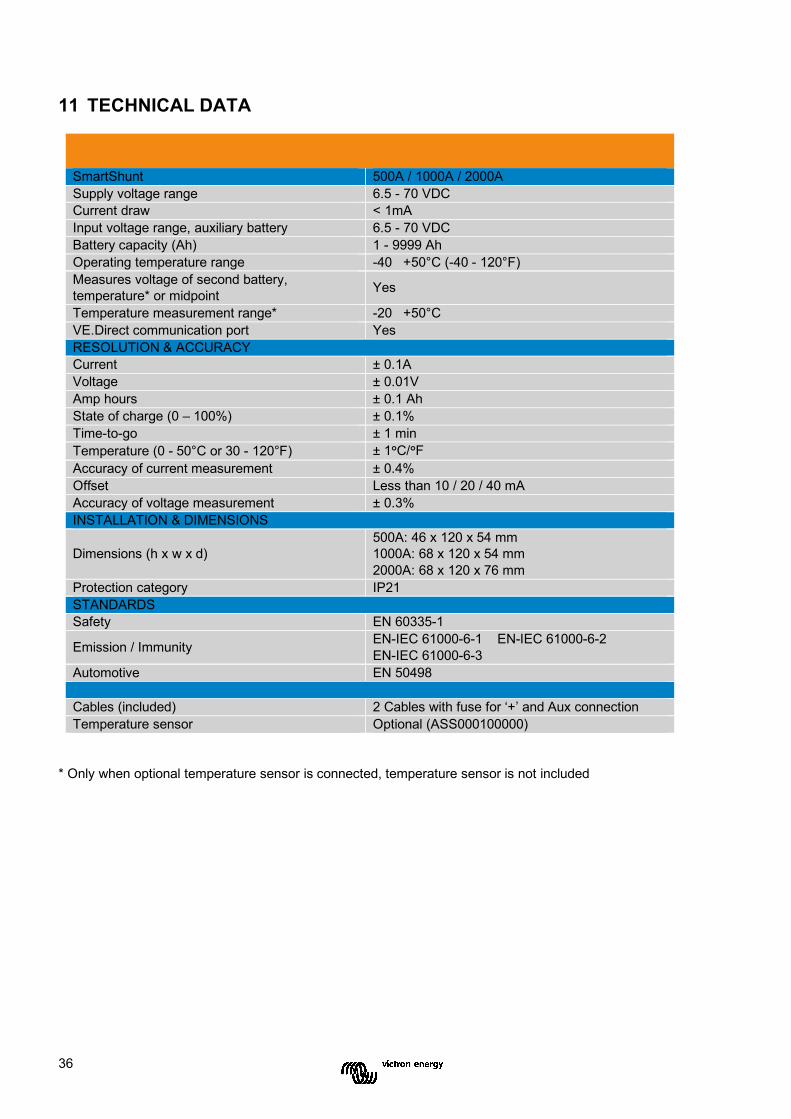
36
11 TECHNICAL DATA
SmartShunt 500A / 1000A / 2000A Supply voltage range 6.5 - 70 VDC Current draw < 1mA Input voltage range, auxiliary battery 6.5 - 70 VDC Battery capacity (Ah) 1 - 9999 Ah Operating temperature range -40 +50°C (-40 - 120°F) Measures voltage of second battery, temperature* or midpoint Yes Temperature measurement range* -20 +50°C VE.Direct communication port Yes RESOLUTION & ACCURACY Current ± 0.1A Voltage ± 0.01V Amp hours ± 0.1 Ah State of charge (0 – 100%) ± 0.1% Time-to-go ± 1 min Temperature (0 - 50°C or 30 - 120°F) ± 1°C/°F Accuracy of current measurement ± 0.4% Offset Less than 10 / 20 / 40 mA Accuracy of voltage measurement ± 0.3% INSTALLATION & DIMENSIONS
Dimensions (h x w x d) 500A: 46 x 120 x 54 mm 1000A: 68 x 120 x 54 mm 2000A: 68 x 120 x 76 mm
Protection category IP21 STANDARDS Safety EN 60335-1
Emission / Immunity EN-IEC 61000-6-1 EN-IEC 61000-6-2 EN-IEC 61000-6-3
Automotive EN 50498 Cables (included) 2 Cables with fuse for ‘+’ and Aux connection Temperature sensor Optional (ASS000100000)
* Only when optional temperature sensor is connected, temperature sensor is not included

37
Distributor: Serial number: Version : 00 Date : March 30th, 2020 Victron Energy B.V. De Paal 35 | 1351 JG Almere PO Box 50016 | 1305 AA Almere | The Netherlands General phone : +31 (0)36 535 97 00 E-mail : [email protected] www.victronenergy.com
Victron Energy Blue Power