manual 7728v1.0 medion
DESCRIPTION
ManualTRANSCRIPT
Thank you for choosing the 7728 v1.X Series (MS-7728 v1.X) Micro-ATX mainboard. The 7728 v1.X Series mainboards are based on Intel® H61 chipsets for optimal system efficiency. Designed to fit the advanced Intel®
LGA1155 processor, the 7728 v1.X Series deliver a high performance and professional desktop platform solution.
Chapter 1
Getting Started
1-2
Getting Started
Mainboard Specifications
Processor SupportIntel® Sandy Bridge processor in the LGA1155 package
ChipsetIntel® H61 chipset
Memory Support2 DDR3 DIMMs support DDR3 1333/ 1066 DRAM (16GB Max)Supports Dual-Channel mode
LANSupports LAN 10/100/1000 by Intel® 82579
AudioHD audio codec integrated by Realtek® ALC887Flexible 5.1-channel audio with jack sensing
SATA4 SATA 3Gb/s ports by Intel® H61 PCH
USB 3.02 USB 3.0 ports by RENESAS uPD720200AF1-DAP-A -The FW version is 4.0.1.5
■
■
■■
■
■■
■
■■
1-3
MS-7728
Chapter 1
Connectors/ PortsBack panel
1 PS/2 keyboard port1 PS/2 mouse port4 USB 2.0 ports1 HDMI port* 1 VGA port*1 LAN port3 flexible audio ports
*(The HDMI and VGA ports only work with Integrated Graphics Processor)On-Board
2 USB 3.0 ports2 USB 2.0 connectors1 Front Panel Audio connector
Slots1 PCIE x16 slot2 PCIE x1 slots
Form FactorMicro-ATX (24.5 cm X 21.5 cm)
Mounting 6 mounting holes
■-------
■---
■■
■
■
1-4
Getting Started
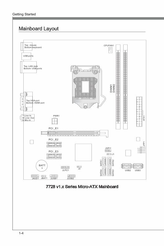
7728 v1.x Series Micro-ATX Mainboard
Mainboard Layout
PCI _E3
PCI _E2
PCI _E1
BATT+
JUSB1JBAT1JAUD1 JUSB2
JLPC1J2
PWR1
CPUFAN1
ATX1
DIM
M1
DIM
M2
USB3USB2
J1
JSPI1
Top: LAN JackBottom: USB ports
USB ports
Top:VGA portBottom: HDMI port
T:Line-InM:Line- OutB:Mic-In
JFP1
SAT
A1
SAT
A4
SAT
A2
SAT
A3
Top : mouseBottom:keyboard
This chapter provides you with the information about hardware setup procedures. While performing the instal-lation, be careful in holding the components and follow-ing the installation procedures. For some components, if you install in the wrong orientation, the components will not work properly.Use a grounded wrist strap before handling computer components. Static electricity may damage the compo-nents.
Chapter 2
Hardware Setup
2-2
Hardware Setup MS-7728
Chapter 2
Hardware Setup MS-7728
Chapter 2
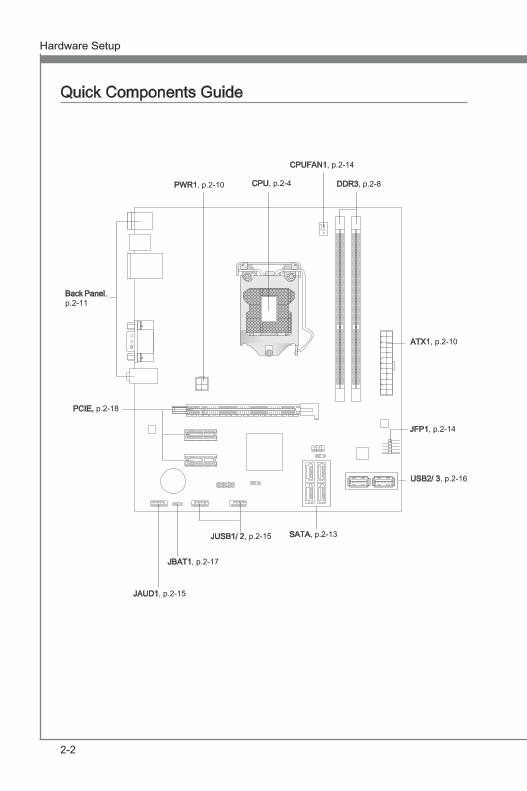
Quick Components Guide
Back Panel, p.2-11
CPU, p.2-4
CPUFAN1, p.2-14
DDR3, p.2-8PWR1, p.2-10
PCIE, p.2-18
JAUD1, p.2-15
JBAT1, p.2-17
JUSB1/ 2, p.2-15
JFP1, p.2-14
SATA, p.2-13
ATX1, p.2-10
USB2/ 3, p.2-16
Hardware Setup MS-7728
Chapter 2
2-3
Hardware Setup MS-7728
Chapter 2
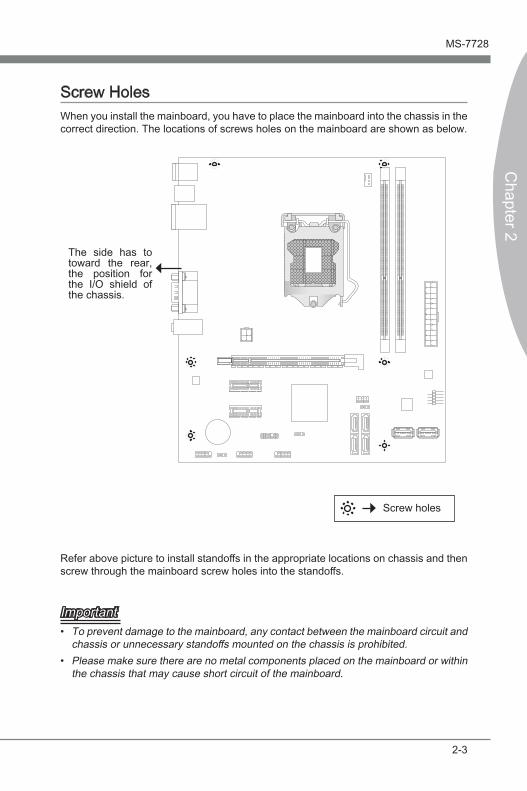
Screw HolesWhen you install the mainboard, you have to place the mainboard into the chassis in the correct direction. The locations of screws holes on the mainboard are shown as below.
Refer above picture to install standoffs in the appropriate locations on chassis and then screw through the mainboard screw holes into the standoffs.
ImportantTo prevent damage to the mainboard, any contact between the mainboard circuit and chassis or unnecessary standoffs mounted on the chassis is prohibited.Please make sure there are no metal components placed on the mainboard or within the chassis that may cause short circuit of the mainboard.
•
•
Screw holes
The side has to toward the rear, the position for the I/O shield of the chassis.
2-4
Hardware Setup MS-7728
Chapter 2
Hardware Setup MS-7728
Chapter 2
CPU (Central Processing Unit)When you are installing the CPU, make sure to install the cooler to prevent overheating. If you do not have the CPU cooler, consult your dealer before turning on the computer.
ImportantOverheatingOverheating will seriously damage the CPU and system. Always make sure the cooling fan can work properly to protect the CPU from overheating. Make sure that you apply an even layer of thermal paste (or thermal tape) between the CPU and the heatsink to enhance heat dissipation.Replacing the CPUWhile replacing the CPU, always turn off the ATX power supply or unplug the power supply’s power cord from the grounded outlet first to ensure the safety of CPU.
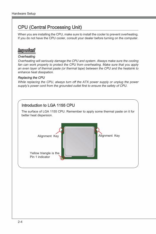
Introduction to LGA 1155 CPUThe surface of LGA 1155 CPU. Remember to apply some thermal paste on it for better heat dispersion.
Alignment Key
Yellow triangle is the Pin 1 indicator
Alignment Key
Hardware Setup MS-7728
Chapter 2
2-5
Hardware Setup MS-7728
Chapter 2
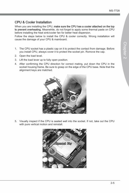
CPU & Cooler InstallationWhen you are installing the CPU, make sure the CPU has a cooler attached on the top to prevent overheating. Meanwhile, do not forget to apply some thermal paste on CPU before installing the heat sink/cooler fan for better heat dispersion. Follow the steps below to install the CPU & cooler correctly. Wrong installation will cause the damage of your CPU & mainboard.
The CPU socket has a plastic cap on it to protect the contact from damage. Before you install CPU, always cover it to protect the socket pin. Romove the cap. Open the load level. Lift the load lever up to fully open position.After confirming the CPU direction for correct mating, put down the CPU in the socket housing frame. Be sure to grasp on the edge of the CPU base. Note that the alignment keys are matched.
1.
2.3.4.
Alignment Key
Alignment Key
Visually inspect if the CPU is seated well into the socket. If not, take out the CPU with pure vertical motion and reinstall.
5.
2-6
Hardware Setup MS-7728
Chapter 2
Hardware Setup MS-7728
Chapter 2
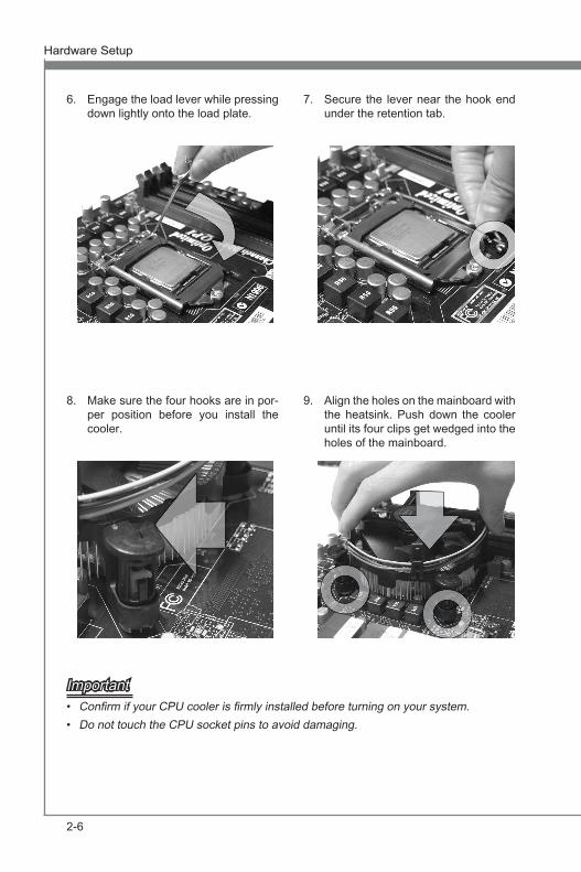
Engage the load lever while pressing down lightly onto the load plate.
6. Secure the lever near the hook end under the retention tab.
7.
Make sure the four hooks are in por-per position before you install the cooler.
8. Align the holes on the mainboard with the heatsink. Push down the cooler until its four clips get wedged into the holes of the mainboard.
9.
ImportantConfirm if your CPU cooler is firmly installed before turning on your system.Do not touch the CPU socket pins to avoid damaging.
••
Hardware Setup MS-7728
Chapter 2
2-7
Hardware Setup MS-7728
Chapter 2
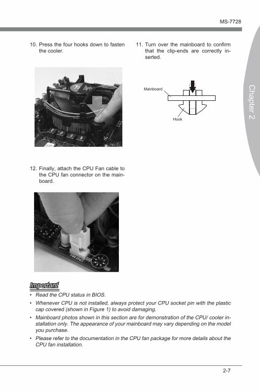
Mainboard
Hook
ImportantRead the CPU status in BIOS.Whenever CPU is not installed, always protect your CPU socket pin with the plastic cap covered (shown in Figure 1) to avoid damaging.Mainboard photos shown in this section are for demonstration of the CPU/ cooler in-stallation only. The appearance of your mainboard may vary depending on the model you purchase.Please refer to the documentation in the CPU fan package for more details about the CPU fan installation.
••
•
•
Press the four hooks down to fasten the cooler.
10. Turn over the mainboard to confirm that the clip-ends are correctly in-serted.
11.
Finally, attach the CPU Fan cable to the CPU fan connector on the main-board.
12.
2-8
Hardware Setup MS-7728
Chapter 2
Hardware Setup MS-7728
Chapter 2
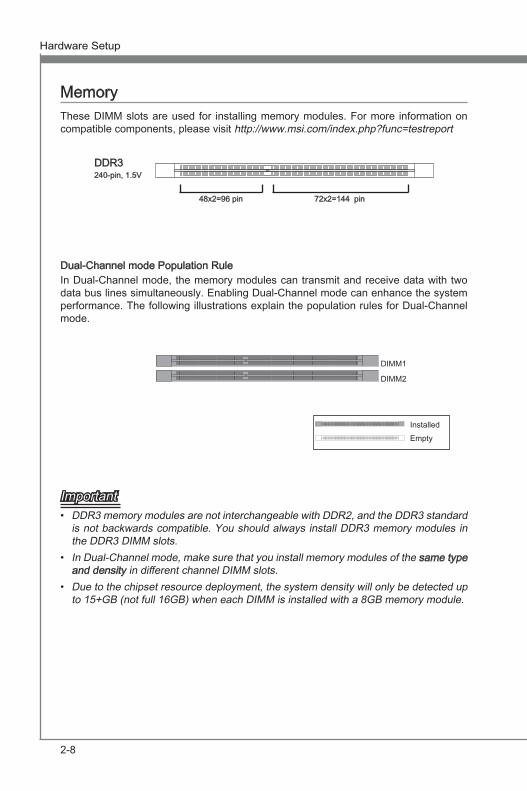
MemoryThese DIMM slots are used for installing memory modules. For more information on compatible components, please visit http://www.msi.com/index.php?func=testreport
DDR3240-pin, 1.5V
48x2=96 pin 72x2=144 pin
Dual-Channel mode Population RuleIn Dual-Channel mode, the memory modules can transmit and receive data with two data bus lines simultaneously. Enabling Dual-Channel mode can enhance the system performance. The following illustrations explain the population rules for Dual-Channel mode.
DIMM1
DIMM2
ImportantDDR3 memory modules are not interchangeable with DDR2, and the DDR3 standard is not backwards compatible. You should always install DDR3 memory modules in the DDR3 DIMM slots.In Dual-Channel mode, make sure that you install memory modules of the same type and density in different channel DIMM slots.Due to the chipset resource deployment, the system density will only be detected up to 15+GB (not full 16GB) when each DIMM is installed with a 8GB memory module.
•
•
•
InstalledEmpty
Hardware Setup MS-7728
Chapter 2
2-9
Hardware Setup MS-7728
Chapter 2
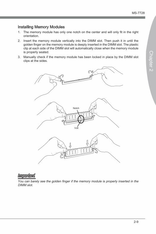
Installing Memory ModulesThe memory module has only one notch on the center and will only fit in the right orientation.Insert the memory module vertically into the DIMM slot. Then push it in until the golden finger on the memory module is deeply inserted in the DIMM slot. The plastic clip at each side of the DIMM slot will automatically close when the memory module is properly seated.Manually check if the memory module has been locked in place by the DIMM slot clips at the sides.
Notch
Volt
ImportantYou can barely see the golden finger if the memory module is properly inserted in the DIMM slot.
1.
2.
3.
2-10
Hardware Setup MS-7728
Chapter 2
Hardware Setup MS-7728
Chapter 2
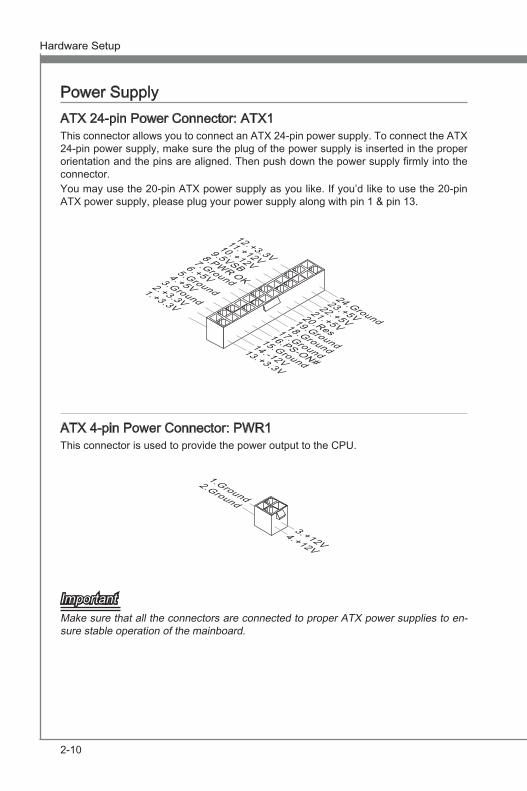
Power SupplyATX 24-pin Power Connector: ATX1This connector allows you to connect an ATX 24-pin power supply. To connect the ATX 24-pin power supply, make sure the plug of the power supply is inserted in the proper orientation and the pins are aligned. Then push down the power supply firmly into the connector.You may use the 20-pin ATX power supply as you like. If you’d like to use the 20-pin ATX power supply, please plug your power supply along with pin 1 & pin 13.
13.+3.3V
1.+3.3V
14.-12V
2.+3.3V
15.Ground
3.Ground
16.PS-ON#
4.+5V
17.Ground
5.Ground
18.Ground
6.+5V
19.Ground
7.Ground
22.+5V
10.+12V
20.Res
8.PWR OK
23.+5V
11.+12V
21.+5V
9.5VSB
24.Ground
12.+3.3V
ATX 4-pin Power Connector: PWR1This connector is used to provide the power output to the CPU.
4.+12V
2.Ground
3.+12V
1.Ground
ImportantMake sure that all the connectors are connected to proper ATX power supplies to en-sure stable operation of the mainboard.
Hardware Setup MS-7728
Chapter 2
2-11
Hardware Setup MS-7728
Chapter 2
Back Panel
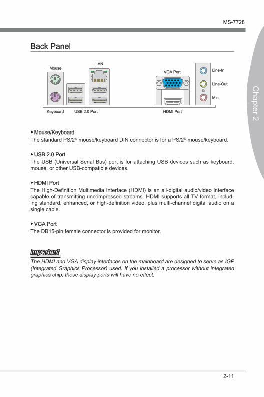
Mouse/KeyboardThe standard PS/2® mouse/keyboard DIN connector is for a PS/2® mouse/keyboard.
USB 2.0 PortThe USB (Universal Serial Bus) port is for attaching USB devices such as keyboard, mouse, or other USB-compatible devices.
HDMI PortThe High-Definition Multimedia Interface (HDMI) is an all-digital audio/video interface capable of transmitting uncompressed streams. HDMI supports all TV format, includ-ing standard, enhanced, or high-definition video, plus multi-channel digital audio on a single cable.
VGA PortThe DB15-pin female connector is provided for monitor.
ImportantThe HDMI and VGA display interfaces on the mainboard are designed to serve as IGP (Integrated Graphics Processor) used. If you installed a processor without integrated graphics chip, these display ports will have no effect.
▶
▶
▶
▶
HDMI Port
Line-In
Line-Out
Mic
VGA PortMouse
USB 2.0 Port
LAN
Keyboard
2-12
Hardware Setup MS-7728
Chapter 2
Hardware Setup MS-7728
Chapter 2
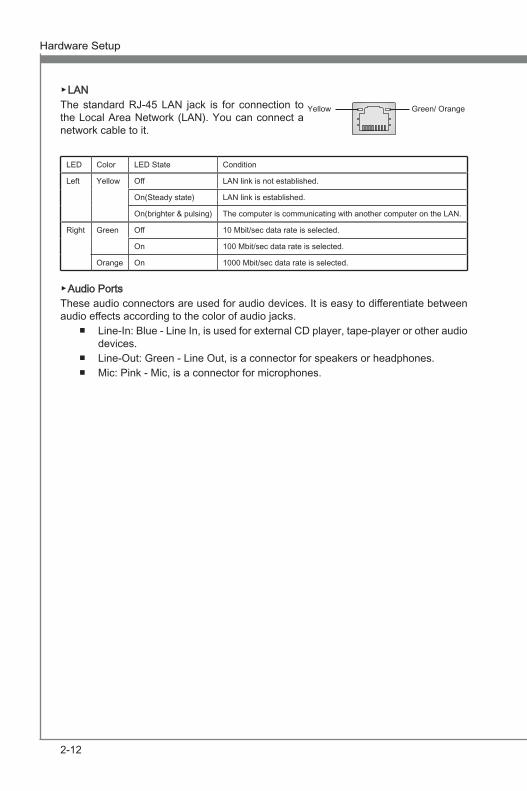
LAN The standard RJ-45 LAN jack is for connection to the Local Area Network (LAN). You can connect a network cable to it.
LED Color LED State Condition
Left Yellow Off LAN link is not established.
On(Steady state) LAN link is established.
On(brighter & pulsing) The computer is communicating with another computer on the LAN.
Right Green Off 10 Mbit/sec data rate is selected.
On 100 Mbit/sec data rate is selected.
Orange On 1000 Mbit/sec data rate is selected.
Audio PortsThese audio connectors are used for audio devices. It is easy to differentiate between audio effects according to the color of audio jacks.
Line-In: Blue - Line In, is used for external CD player, tape-player or other audio devices. Line-Out: Green - Line Out, is a connector for speakers or headphones.Mic: Pink - Mic, is a connector for microphones.
▶
▶
■
■■
Yellow Green/ Orange
Hardware Setup MS-7728
Chapter 2
2-13
Hardware Setup MS-7728
Chapter 2
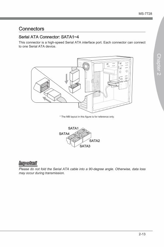
ConnectorsSerial ATA Connector: SATA1~4 This connector is a high-speed Serial ATA interface port. Each connector can connect to one Serial ATA device.
* The MB layout in this figure is for reference only.
SATA1
SATA3SATA2
SATA4
ImportantPlease do not fold the Serial ATA cable into a 90-degree angle. Otherwise, data loss may occur during transmission.
2-14
Hardware Setup MS-7728
Chapter 2
Hardware Setup MS-7728
Chapter 2
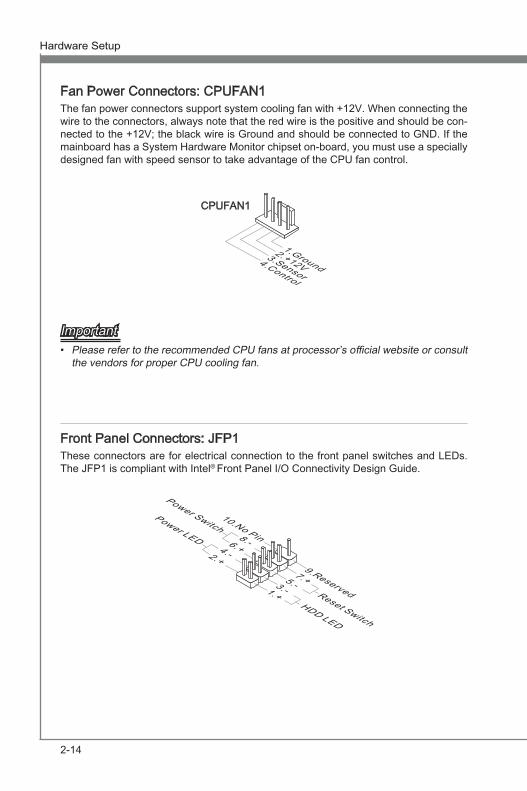
Fan Power Connectors: CPUFAN1The fan power connectors support system cooling fan with +12V. When connecting the wire to the connectors, always note that the red wire is the positive and should be con-nected to the +12V; the black wire is Ground and should be connected to GND. If the mainboard has a System Hardware Monitor chipset on-board, you must use a specially designed fan with speed sensor to take advantage of the CPU fan control.
1.Ground2.+12V
3.Sensor4.Control
CPUFAN1
ImportantPlease refer to the recommended CPU fans at processor’s official website or consult the vendors for proper CPU cooling fan.
Front Panel Connectors: JFP1These connectors are for electrical connection to the front panel switches and LEDs. The JFP1 is compliant with Intel® Front Panel I/O Connectivity Design Guide.
1.+3.-
10.No Pin
5.-Reset Switch
HDD LED
Power SwitchPower LED
7.+9.Reserved
8.-6.+4.-2.+
•
Hardware Setup MS-7728
Chapter 2
2-15
Hardware Setup MS-7728
Chapter 2
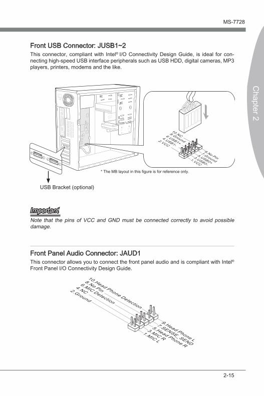
Front USB Connector: JUSB1~2This connector, compliant with Intel® I/O Connectivity Design Guide, is ideal for con-necting high-speed USB interface peripherals such as USB HDD, digital cameras, MP3 players, printers, modems and the like.
115
V
1.VCC
3.USB0-
10.NC
5.USB0+
7.Ground
9.No Pin
8.Ground6.USB1+
4.USB1-2.VCC
* The MB layout in this figure is for reference only.
USB Bracket (optional)
ImportantNote that the pins of VCC and GND must be connected correctly to avoid possible damage.
Front Panel Audio Connector: JAUD1This connector allows you to connect the front panel audio and is compliant with Intel®
Front Panel I/O Connectivity Design Guide.
1.MIC L
3.MIC R
10.Head Phone Detection
5.Head Phone R
7.SENSE_SEND
9.Head Phone L
8.No Pin6.MIC Detection
4.NC2.Ground
2-16
Hardware Setup MS-7728
Chapter 2
Hardware Setup MS-7728
Chapter 2
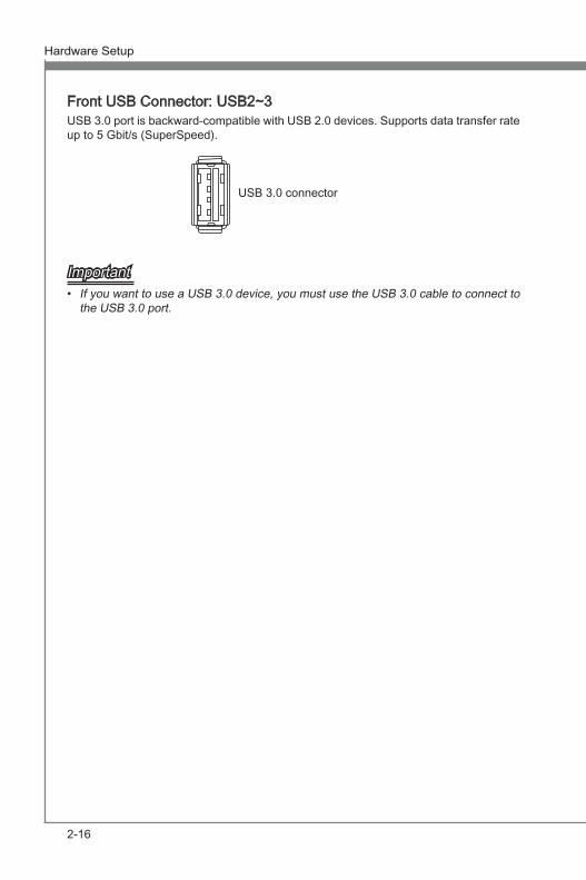
Front USB Connector: USB2~3USB 3.0 port is backward-compatible with USB 2.0 devices. Supports data transfer rate up to 5 Gbit/s (SuperSpeed).
USB 3.0 connector
ImportantIf you want to use a USB 3.0 device, you must use the USB 3.0 cable to connect to the USB 3.0 port.
•
Hardware Setup MS-7728
Chapter 2
2-17
Hardware Setup MS-7728
Chapter 2
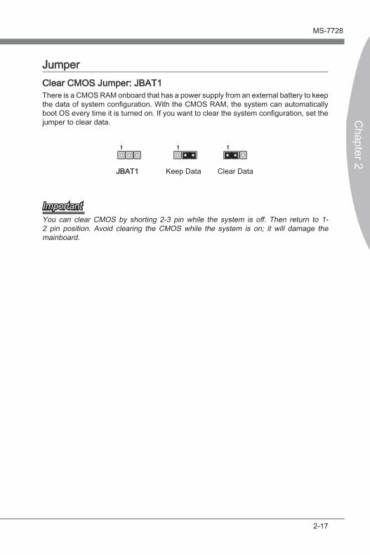
JumperClear CMOS Jumper: JBAT1There is a CMOS RAM onboard that has a power supply from an external battery to keep the data of system configuration. With the CMOS RAM, the system can automatically boot OS every time it is turned on. If you want to clear the system configuration, set the jumper to clear data.
JBAT1 Keep Data Clear Data
1 11
ImportantYou can clear CMOS by shorting 2-3 pin while the system is off. Then return to 1-2 pin position. Avoid clearing the CMOS while the system is on; it will damage the mainboard.
2-18
Hardware Setup MS-7728
Chapter 2
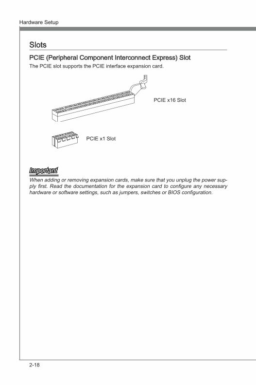
SlotsPCIE (Peripheral Component Interconnect Express) SlotThe PCIE slot supports the PCIE interface expansion card.
PCIE x16 Slot
PCIE x1 Slot
ImportantWhen adding or removing expansion cards, make sure that you unplug the power sup-ply first. Read the documentation for the expansion card to configure any necessary hardware or software settings, such as jumpers, switches or BIOS configuration.