manual automatic meter reading systems - lsis
TRANSCRIPT

Electric Equipment
Manual
Automatic Meter Reading Systems

Automatic Meter Reading Systemg y
1

ContentsContents
I. Automatic meter reading system overview
1. Automatic meter reading system overview
2. Use and features
3. System configuration
4
5
6
II. Electronic watt-hour meter
1. LD1210DR-040/080/120 Type
2. LD3410DR-040/080/120 Type
3 LM1210DR 040/080/120R R T
9
15
213. LM1210DR-040/080/120R Remote Type
III. Home Control Unit ( HCU )
1. Single unit type HCU-E
21
30
2. Module type HCUM-E
IV. Central Control Unit ( CCU )
V HCU LOADER
41
46
51V. HCU LOADER 51
2

I. Automatic meter reading
system overview
3

1. Automatic meter reading system overview
Automatic meter reading system
1. Automatic meter reading system overview
An advanced system that enables automatic meter reading, convenient
searching and printing of data from various meters for electricity, gas,
h l i i ll d i h ffi f h
1.1 Definition
water, hot-water, calorie installed in an apartment house or office from the
metering center in the administration office without the meter-reading
personnel having to visit each house to take the values.
hot-watergas
calorie
water Reading data
electricity Reading center (Administration office)
(House)
[Automatic meter reading system overview]
1.2 Communication method
Exclusive line type automatic meter reading system
RS-485 exclusive line is used for communication between HCU or
electronic watt-hour meter installed in each house and CCU installed in
the reading center.
4

1 3 Benefit of introduction of the automatic meter reading system1.3 Benefit of introduction of the automatic meter reading system
● Creation of new residential culture through introduction of advanced system
● Enhanced housing quality through elegant design of each equipment
● No dispute over wrong reading by reading personnel
● Prevention of crime by fake reading personnel and privacy invention
● Saving of general management expenses through automated reading
● Efficient energy management using automatic meter reading data
● Office-tel
2.1 Use
2. Use and features
● Residential and commercial complex
● Apartment complex
● Stores
● Factory (apartment factory), etc.
2.2 Features
● Connection and reading of 6 different meter types
● Electronic watt-hour meter functions as a HCU
● Extension of communication distance and maintenance of optimal
communication status through routing function (No need for a separate
router as the product has integrated routing function)
● Provision of various reading information (Daily report, monthly report,
usage trend graph, etc.)
5
usage trend graph, etc.)
● Preservation of data and normal reading operation during blackout
● Elegant and sophisticated design

3 System configuration
Automatic meter reading system
● Pulse type meter
· Watt-hour meter, gas meter, water meter, hot-water meter, cooling
meter, calorimeter, etc.
3. System configuration
● HCU
· Receives pulse signal from the meter, saves and displays meter value
meter, calorimeter, etc.
· Integrated pulse generator (pulse type instrument)
p g , p y
(sequential display)
· Data transfer (exclusive line) from the CCU
Exclusive lineExposed type HCUM-E/HCU-E
Category Installation type Model
Exclusive linetype
● El t i tt h t ith i t t d t ti t di
Flush type HCU-E Te
● Electronic watt-hour meter with integrated automatic meter reading
· Metering of electric power usage (Class 1.0 precision measurement)
· Input and storage of other meter pulse such as gas, water, hot-water, etc.
· Data transfer to the CCU
· Execution of both electronic watt-hour meter and HCU functions
6

● Central Control Unit (CCU)
· Collects and stores meter reading data from HCU
· Transfers stored data to the meter reading computer (RS-232C)
Integrated type (Rack installation) CCU-E2(Rack)
Category Installation type Model
Exclusive linetype single unit type CCU-E2
● Meter reading computer and software
· Meter reading software operation. Management and storage of meter g p g g
reading data
· Communication with CCU (RS-232)
7

II. Electronic watt-hour meter
1) Electronic watt-hour meter1) Electronic watt hour meter
2) Remote integrated type
watt-hour metera ou e e
8

LD1210DR-040/080/120
Automatic meter reading system
This series of electronic watt-hour meter is able to continuously accumulates
ff i h i hi h d di
1. Overview
effective watt-hour in a very high accuracy and output corresponding
proportional pulse. Size has been minimized by type. And, up-and-down and
left-and-right types facilitate installation and convenience during use is
considered.
2 Rated values and specification2. Rated values and specification
Model
LD1210DR-040Category
Type Up and down, left and right type (U/L, R/L)
Standard (S-TYPE), Pulse (P-TYPE), Remote (R-TYPE)
LD1210DR-080 LD1210DR-120
Function
Phase type
Rated voltage
Rated current
Instrument class
Instrument
single-phase 2 wire type (single unit)
220 V
Class 1.0
yp p , g yp ( , )
40(10)A 80(20)A 120(30)A
Instrument constant
60Hz
Power consumption
Output pulseinstrument
constant
1000 Pulse/kWh
10 Pulse/kWh
500 Pulse/kWh 250 Pulse/kWh
1000 Pulse/kWh1000 Pulse/kWh
Frequency
Below 2W
Base unit: Phenol (Black)Cover: Polycarbonate (Opaque)
Material
Weather resistant structure
consumption
S I Z E 66(W) X 130(H) X 65(D)
Operating temperature: -20℃~ 45 ℃, Storage temperature: -20℃~ 70 ℃, Environment
Indoor type instrument
9
p g p ℃ ℃, g p ℃ ℃,Altitude: below 2000 m
Environment

※ LD1210DR model name※ LD1210DR model name
3. Appearance by type
Figure 1. Up and down type (U/L TYPE) Figure 2. Left and right type (R/L TYPE)
■ Cable type
10

4. Major function4 1 Bl k di
Automatic meter reading system
4.1 Block diagram
Power SupplyCircuit
EnergyMeasurement
Circuit
Micro-Processor
LCD Display
Block
Circuit
Current SenseCircuit
Processor
N Block DiagramT N
4.2 Circuit configuration
1) Power Supply Circuit
2) Current Sense Circuit2) Current Sense Circuit
3) Energy Measurement Circuit
4) Micro-Processor
5) LCD Display
4.3 Function description
1) Measurement of effective watt-hour Measured value indicates the effective forward watt-hour, total sum after installation.
2) Display function Display of the watt-hour meter consists of LCD and LED.
3) Pulse output function (pulse type) Pulse type electronic watt hour meter has a function to output a pulse that is
p
■ Output pulse width: 70 msec
■ Output method : Open Collector
■ Output line specification
White: Wh
Pulse type electronic watt-hour meter has a function to output a pulse that is proportional to the used watt-hour.
11
Figure. Pulse output method
Black: Ground
■ Keep Vcc below 30V and Ic below 6mA.

5. How to read the display
5.1 LCD display specification
Displays total watt-hour used in 00000.0~99999.9[kWh] range. Accumulated usage displayed on the LCD starts from “0” after reaching the maximum.
1) Indicates normal operation of the instrument: Flashing varies depending on
5.2 Description of the display
) p g p gthe load.
2) Indicates the type of the current value: Sequentially scrolls if automatic meter reading system is implemented.(For automatic meter reading)
3) Displays the accumulated watt-hour up to now.
4) Indicates the unit of the displayed item: electricity
5) Indicates the unit of the displayed item: gas, water, hot-water, heating, cooling. (For automatic meter reading)
6 Installation guide
6.1 Installation of the product
1) Fix the watt-hour meter in the housing so that the meter cannot move.
2) Strip end of both the power and load cords about 20mm.
3) Loosen terminal screws of the watt-hour meter, put from N phase load side cord into the terminal and then tighten the terminal screws.
4) Repeat the same procedure for the power side cord.
12
5) Engage the power and check if the display of the watt-hour meter operates normally.
6) Seal off the terminals after installation is finished.

6.2 Wiring of the watt-hour meter
Automatic meter reading system
g
Wiring of the watt-hour meter should be done as shown below.
!
Warning
1. Wiring should only be performed by personnel with national certification.
2. Carefully check and observe the power system and do the wiring with specialattention to the phase type and rated voltage.
!
Caution
Tightening torque of the external wiring bolt is 11~14kgf.㎝ for 40A, 39~49kgf.㎝
for 80A·120A.
(Tightening with excessive may cause wear or damage of the screws.)
Be careful of the bad contact during wiring work
(Wrong wiring may cause damage on the watt-hour meter and human body.)
13
Be careful of the bad contact during wiring work.
There is risk of damage and fire due to open power supply and current.

7. Check of contents and storage
7.1 Check of contents
Before installation of the watt-hour meter, check the package according to the list below if there is any discrepancy. For any deviation, contact our headquarter, factory or closest service center.
▶ Low voltage electronic watt-hour meter : 1 unit
▶ User manual: 1 set
▶ Check that the rated value and capacity corresponds to the specification
▶ Check if there is any damage on the product during transportation
▶ Check if the sealing lead of the watt hour meter is sealed▶ Check if the sealing lead of the watt-hour meter is sealed
7.2 Transportation and storage
Precautions to transportation and storage of the watt-hour meter is as followsfollows.
1) Do not apply large shock during transportation and storage.
(This product is a sensitive electronic product and subject to damage if physical shock is applied to the product. Please, be reminded that we are not responsible for product damage due to vibration or shock during transportation and storage.)
2) Avoid exposure to rain, wind, humidity, harmful gas, chemical substance (volatile substance such as thinner, benzene), excessive vibration, direct sunlight or heater.
3) Handle the product with care in order not to damage or scratch the instrument.
14

LD3410DR-040/080/120
Automatic meter reading system
1. Overview
This series of electronic watt-hour meter is able to continuously
2 Rated values and specification
accumulates effective forward direction watt-hour in a very high
accuracy and output corresponding proportional pulse. Size has been
minimized by type. And, up-and-down and left-and-right types facilitate
installation by environment and convenience during use is considered.
Standard (S-TYPE), Pulse (P-TYPE), Remote (R-TYPE)
Up and down left and right type (U/L R/L)
Model
LD3410DR-040Category
Function
LD3410DR-080 LD3410DR-120
Type
2. Rated values and specification
Class 1.0
Up and down, left and right type (U/L, R/L)
Three-phase 4 wire type (single unit)
220/380 V
Type
Phase type
Rated voltage
40(10)A 80(20)A 120(30)ARated current
Instrument class
B l 2W
60Hz
500 Pulse/kWh 250 Pulse/kWh 125 Pulse/kWhInstrument constant
Output pulseinstrument
constant
Frequency
Power
500 Pulse/kWh 250 Pulse/kWh 125 Pulse/kWh
Indoor type instrument
Base unit: Phenol (black)
Cover: Polycarbonate(opaque)
114(W) X 130(H) X 65(D)
Below 2Wconsumption
S I Z E
Material
Weather resistant structure
15
Operating temperature: -20℃~ 45 ℃, Storage temperature: -20℃~ 70 ℃, Altitude: below 2000 m
Environment
structure

※ LD3410DR model name※ LD3410DR model name
3. Appearance by type
Figure 1. Up and down type (U/L TYPE) Figure 2. Left and right type (R/L TYPE)
■ Cable type
16

Automatic meter reading system
4. Major function4 1 Bl k di
Power SupplyCircuit
EnergyM Micro-
LCD Display
4.1 Block diagram
Measurement Circuit
Current SenseCircuit
MicroProcessor
Block DiagramT NSR
4.2 Circuit configuration
1) Power Supply Circuit
2) Current Sense Circuit2) Current Sense Circuit
3) Energy Measurement Circuit
4) Micro-Processor
5) LCD Display
4.3 Function description
1) Measurement of effective watt-hour Measured value indicates the effective forward watt-hour, total sum after installation.
2) Display function Display of the watt-hour meter consists of LCD and LED.
3) Pulse output function (pulse type) Pulse type electronic watt-hour meter has a function to output a pulse that is proportional to the used watt-hour.
■ Output pulse width: 70 msec
■ Output method : Open Collector
■ Output line specification
White: Wh
17
Figure. Pulse output method
Black: Ground
■ Keep Vcc below 30V and Ic below 6mA.

5. How to read the display
5.1 LCD display specification
1) Indicates normal operation of the instrument: Flashing varies depending
5.2 Description of the display
Displays total watt-hour used in 00000.0~99999.9[kWh] range. Accumulated usage displayed on the LCD starts from “0” after reaching the maximum.
) p g p gon the load.
2) Indicates the type of the current value: Sequentially scrolls if automatic meter reading system is implemented.(For automatic meter reading)
3) Displays the accumulated watt-hour up to now.
4) Indicates the unit of the displayed item: electricity
6.1 Installation of the product
6 Installation guide
5) Indicates the unit of the displayed item: gas, water, hot-water, heating, cooling. (For automatic meter reading)
1) Fix the watt-hour meter in the housing so that the meter cannot move.
2) Strip end of both the power and load cords about 20mm.
3) Loosen terminal screws of the watt-hour meter, put from N phase load side cord into the terminal and then tighten the terminal screws.
4) Repeat the same procedure for the power side cord.
18
5) Engage the power and check if the display of the watt-hour meter operates normally.
6) Seal off the terminals after installation is finished.

Automatic meter reading system
6.2 Wiring of the watt-hour meter
Wiring of the watt-hour meter should be done as shown below.
!
Caution
Tightening torque of the external wiring bolt is 11~14kgf.㎝ for 40A, 39~49kgf.㎝
for 80A·120A.
(Tightening with excessive may cause wear or damage of the screws.)
!
Warning
1. Wiring should only be performed by personnel with national certification.
2. During wiring of the watt-hour meter, be careful of the RSTN phase order.
(Wrong wiring may cause damage on the watt-hour meter and human body.)
Be careful of the bad contact during wiring work.
There is risk of damage and fire due to open power supply and current.
19

7. Check of contents and storage
7.1 Check of contents
Before installation of the watt-hour meter, check the package according to the list below if there is any discrepancy. For any deviation, contact our headquarter, factory or closest service center.
▶ Low voltage electronic watt-hour meter : 1 unit
▶ User manual: 1 set
▶ Check that the rated value and capacity corresponds to the specification
▶ Check if there is any damage on the product during transportation
▶ Check if the sealing lead of the watt hour meter is sealed▶ Check if the sealing lead of the watt-hour meter is sealed
7.2 Transportation and storage
Precautions to transportation and storage of the watt-hour meter is as followsfollows.
1) Do not apply large shock during transportation and storage.
(This product is a sensitive electronic product and subject to damage if physical shock is applied to the product. Please, be reminded that we are not responsible for product damage due to vibration or shock during transportation and storage.)
2) Avoid exposure to rain wind humidity harmful gas chemical substance2) Avoid exposure to rain, wind, humidity, harmful gas, chemical substance (volatile substance such as thinner, benzene), excessive vibration, direct sunlight or heater.
3) Handle the product with care in order not to damage or scratch the instrument.
20

Watt-hour meter with integrated automatic meter reading
(LM1210DR-040/080/120R)
Automatic meter reading system
1. Product name
(LM1210DR 040/080/120R)
Single-phase electronic watt-hour meter LM1210DR SERIES
1) LM1210DR model name description
LM 12 10 DR 040 S
S : Standard P : Pulse R : Remote
DiRect connection (single unit)
Class 1 instrument accuracy
single-phase 2 wire type
040 : 40(10)A080 : 80(20)A120 : 120(30)A
1) Standard: Meters only the pure electricity watt-hour value (effective).
2) Types
Original model
2) Pulse: Meters and outputs pulse of only the pure electricity watt-hour
value (effective).
3) Remote: Meters the pure electricity watt-hour value and 5 different (gas,
water, hot-water, cooling, heating) information and transfers the
information to CCU through communication line (exclusive line)
2. Items to check before use
Checklist before use
1) Check that the product specification agrees with the one you ordered.
information to CCU through communication line (exclusive line).
21
2) Check for any components that came off or damaged by accident during
transportation.
3) Check that the watt-hour meter is sealed with sealing lead.

3. Rated values
Model
LM1210DR-040
Standard (S-TYPE), Pulse (P-TYPE), Remote (R-TYPE)
LM1210DR-080 LM1210DR-120
Function
Bottom connection typeType
Single-phase 2 wire type (single unit)Phase type
Category
Single phase 2 wire type (single unit)Phase type
220 VRated voltage
40A 80A 120ARated current
Class 1.0Instrument class
1000 Pulse/kWh 500 Pulse/kWh 250 Pulse/kWhInstrument constant
O l1000 Pulse/kWh
Output pulseinstrument constant
500 Pulse/kWh 250 Pulse/kWh
60HzFrequency
Below 2WPower consumption
108(W) X 140(H) X 60(D)S I Z E
4 Precaution
Base unit: Polycarbonate (strong grey)
Cover: Polycarbonate(white) Material
Indoor type instrumentWeather resistant structure
4. Precaution
1) Make sure to turn off the power before installation of the meter.
▪ Cut off the main switch (single-phase220V or 3 phase power switch).
2) Also, check the power before installation of the meter.
! Warning
) , p
▪ Make sure to check the power as the meter is designed for AC 220V and the
meter may malfunction or may be damaged in the electronic device.
▪ Especially, when engaging three phase power, line voltage(R-S, S-T, T-R) is
380V and it is mandatory to check the power status.
3) Power source side (1S, 2S) needs to be connected first and then load side (2L,
1L) needs to be connected
22
1L) needs to be connected.
4) Location to be installed should be free from rain, wind, humidity, dust, vibration,
shock and direct sunlight. The meter should be installed in vertically and
horizontally up-right position.

5) Installation height should be about 1.8m from the floor so that values could easily
be recognized.
6) A id t l ti th t b fl d d lf ti l t ifi ti
Automatic meter reading system
6) Avoid usage at a location that can be flooded as malfunction or electrification
may result.
7) Avoid a confined space with direct sunlight.
8) The surface of the watt-hour meter must be kept away from volatile substances
such as thinner, benzene, etc.
9) For safety of the installation engineer, never attempt any service when the product
is on live wire.
5. Connection procedure1) Check for the screws inside the terminal block. (Refer to Figure 1)
2) Turn of the power and make the wiring.
3) P f th i i f th id t th l d id di3) Perform the wiring from the power source side to the load side according
to the connection diagram.
4) Remove the wire coating about 23mm, and seal off the dedicated
protection cover (terminal cover) when the connection is over.
Figure 1 M3 screw must be appliedh (1 )here. (1ea)
6. Connection diagram
하부
원
전
1 L2 L2 S1 SC
P
Pulse input (Automatic meter reading type)
Communication terminal
(Automatic meter reading type)
Pulse output (pulse type)
Pow
e
Load
23
L O A D
하
M A I N
원er

1) CABLE wiring method1) CABLE wiring method
① Automatic meter reading type (exclusive line)
- Pulse input line (total 6 lines)
WIRE color meter type
Blue gas
Black water
Yellow hot-water
Green heating
Red cooling
- Communication line (total 4 lines)
Red cooling
White COMMON
WIRE color wiring type
Green CCU (+)
Red CCU (-)
White ROUTER (+)
Black ROUTER (-)
② Pulse type (total 2 lines)
WIRE color wiring type
White (+) polarityWhite (+) polarity
Black (-) polarity
※ Pay attention to the WIRE color and polarity.
24

2) Connection with other system
Automatic meter reading system
Vcc
R
R
White
) y
Ic
▶ Pulse type: pulse output part ▶ Remote integrated type: pulse input part
R
Othersystem
Black
■ Output pulse width: 70 msec
■ Output method: Open collector
■ Output line specification
White: Watt Hour Signal
Black: GNDBlack: GND
■ Conditions to meet: Vcc < 30V, Ic < 6mA
7. Installation procedure
7.1 Installation of the product
1) Fix the watt-hour meter in the housing so that the meter cannot move.
2) Strip end of both the power and load cords about 20mm.
3) Loosen terminal screws of the watt-hour meter, put from N phase load side cord into the terminal and then tighten the terminal screws.
4) Repeat the same procedure for the power side cord.
5) Engage the power and check if the display of the watt-hour meter operates normally.
25

8. Function and operation
Automatic meter reading system
8. Function and ope ation
1) Communication function
In case of automatic meter reading type, LM1210DR SERIES electronic watt-hour
meter adopts the routing function which enables simultaneous connection to multiple
watt-hour meters. Routing function makes it possible to save communication wiring
from the CCU and therefore saves installation cost and facilitates the installationfrom the CCU, and therefore saves installation cost and facilitates the installation
process. Plus, this provides additional benefit of higher chance of successful
communication through intensified communication protocol.
2) Instrument setting function
In case of automatic meter reading type, LM1210DR SERIES electronic watt-hour
meter provides various instrument setting function to include communication ID setting,
routing function setting, communication speed setting, pulse constant and pulse width
setting of 5 different meter types, decimal point, etc. This is made possible by Handy
Loader, an instrument setting device provided by our company. Using this loader, the
system user can change settings depending on various situations.
▶ Example of instrument setting
① Parameter(instrument constant) setting
Setting parameter (other items such as instrument constant, etc.) can be
h d i th h d l d hil f i t th l b l (Schanged using the handy-loader while referring to the example below.(See
HANDY-LOADER user manual to learn how to use the loader.)
☞ e.g.) If pulse specification of:
electricity meter is 1000Pulse/1kWh, set the instrument constant to 1000.
gas meter is 1Pulse/10ℓ, set the instrument constant to 100.
water meter is 1Pulse/100ℓ, set the instrument constant to 10.
calorimeter is 1Pulse/1kWh, set the instrument constant to 1.
② Initial value must be entered after setting of the parameter (instrument
constant or decimal places).
26

Automatic meter reading system
3) LCD display specification
Displays total watt-hour used in 00000.0~99999.9[kWh] range.
Accumulated usage displayed on the LCD starts from “0” after reaching
the maximum.
▶ Description of the display
1) Indicates normal operation of the instrument: Flashing varies depending on the load.
2) Indicates the type of the current value: Sequentially scrolls if automatic meter reading system is implemented. (For automatic meter reading)
3) Displays the accumulated watt-hour up to now.
4) Indicates the unit of the displayed item: electricity
5) Indicates the unit of the displayed item: gas, water, hot-water, heating, cooling. (For automatic meter reading)
27

9. Cable specification
Automatic meter reading system
Rated currentCables used (Number of wires / Diameter of wire)
Minimum Maximum
40A Dia. 2.0mm 14mm2
80A i 8 0 ( /1 2) 38 2 ( /2 6)
10. Year and month manufactured
80A Dia. 8.0mm(7/1.2) 38mm2 (7/2.6)
120A Dia. 14.0mm(7/1.6) 60mm2(19/2.0)
11 Warranty period
Marked on the name plate
11. Warranty period
2.5 years from the manufacturing date
28

III. Home Control Unit ( HCU )
1) Single unit type HCU1) Single unit type HCU
2) Module type HCU
29

Single unit type HCU (HCU-E)
Automatic meter reading system
1. Overview
The HCU takes measurements from the pulse meter(electricity, gas, water, calorimeter, etc.) installed at homes and offices and displays on the LCD, transfers measured values to the CCU through the exclusive line according to the command of the exclusive line CCU When working as a router the HCUthe command of the exclusive line CCU. When working as a router, the HCU transfers the commands from the exclusive line CCU to the exclusive line HCU through exclusive RS-485 line in RS-485 communication method.
2. Feature and function
1) Receiving and saving of pulse signal from the meter
2) Data transfer to the CCU (exclusive line)2) Data transfer to the CCU (exclusive line)
3) DATA display
4) Meter connection : Connection with max. 6 meter units
5) DATA routing: Receives the remote HCU data and transfers the data to the CCU
6) Blackout compensation: Preserves the saved data and normal meter di i ibl i f bl k (72 h )
3-1 Items to check before connection of the power
1) Check that the operating voltage is the rated voltage of AC220V.
reading is possible in case of blackout (72 hours)
3. Precautions to installation and operation
1) Check that the operating voltage is the rated voltage of AC 0V.
2) Commercial frequency is 60Hz.
3) Check wiring status of the meter pulse cables at the pulse input ports.
4) Input of pulse cable and communication line is explained in detail in the user manual. Please, read it carefully and perform the wiring for the pulseand communication lines.
5) Power of the unit must be turned off during installation and check5) Power of the unit must be turned off during installation and check.
→ Failure to do so may cause fatal injury or fatality.
6) Check the connection between the power terminal and the power cable.
3-2 Check list before communication test
1) Ch k h i f l bl i i bl d i l
30
1) Check the connection of pulse cable, communication cable and terminals before the test run.

2) Terminal ID, communication speed, pulse spec, meter spec, meter value need to be configured in the HCU which can be done through Handyneed to be configured in the HCU which can be done through Handy Loader-2000. Refer to the user manual for the handy loader for details of the configuration.
3) Check the display to see if the corresponding ID, “e.g.) 10001” is displayed.
4) Check that the entered meter data are the same with the data scrolled on the display. → Difference may cause issues during settlement of the charge.
5) Check on the display is scrolling is being performed normally.
6) Only trained personnel should perform the communication test and HCU configuration.
3-3 Precautions to storage and handling3 3 Precautions to storage and handling
1) Store the product in a dry and dust-free storage.
2) Do not throw or apply too much force during transportation.
4. Appearance and configuration
LCD display
4-1 Appearance and configuration of the HCU-E
Side view (exposed type) Front view (Both flush type and exposed type)
31
Side view (exposed type) Front view (Both flush type and exposed type)

4-2 Configuration and appearance of the HCU-ETe
Automatic meter reading system
60mmPower cable
Communicationport Pulse
portport
Display(LCD)
LOADERconnectionCPU
power supply
32
supply
< EXTERNAL COVER REMOVED>

5. Rated value and specification
Specification Remark
Communication
speed38400 bps
C i ti
Category
LoaderSerial
5-1 General specification
Communication
methodSemi-biasynchronous
Transport code ASCII
Communication
speed1200~38400 bps, variable
Communication
methodRS-485
Loader
Interface
Communication
specification
Serial
Communication
Exclus ive line
Communication method
Communication
cableShielded 22AWG 1Pair
9 types (electricity, gas, water,
hot-water, calorie, cooling,
heating flow, cooling flow, etc.)
Maximum 6
Type of meter
No. of connected metersConnection
Communication
Dry contact / Open Collector
16 characters × 2 rows
64 × 14 mm
Manufacturing date, HW/SW
version, ID, meter type, usage,
etc
Meter pulse
LCD module spec
Display (LCD)
specification
Size
Display data
etc.
AC 220V(±10%)/60Hz
+ 5 V
4.2 mA
72 hours
Current consumption
Data s torage and metering during blackout
Power source
Input power
Operation power
33

5-2 LCD display specification
Automatic meter reading system
LCD SCROLL interval is 3sec and displayed specification is as follows.
1) Initial screen upon POWER ON (Reset)
① ② ③
H10.S10-00/12/19N 0 * * 6
⑥
------ N 0 * * 6
④ ⑤⑤Catego Description Remark
① HW Version H10 HW Version 1.0
② SW Version S10 SW Version 1.0
③Manufactured
date2000-12-19 Manufactured on 19 Dec 2000
1 P l i d t t 1
Display
1 _ _ _ _ _ Pulse recognized at port 1
1 2 _ _ _ _
_
Pulse recognized at port 1
and 2
1 2 3 4 _ _
_
Pulse recognized at port 1,
2, 3 and 4
1 2 3 4 5 6Pulse recognized at port 1,2, 3, 4, 5 and 6
④
Pulse
recognition
status
N Normal
H Loader connected
R Router operation
* N/A
1 1200 bps
2 2400 bps
3 4800 bpsCommunication
⑥
⑤ HCU status
34
3 4800 bps
4 9600 bps
5 19200 bps
6 38400 bps
speed⑥

2) ID display screen
I D : 0 0 0 0 0------ N 0 * * 6
HCU ID(00000~99999)
- ID may be in 00000~99999 range.
3) Display of meter and usage
① ② ③ ④
1WHM:123456.123N 0 * * 6
① ② ③ ④
------ N 0 * * 6
Category Description Remark
① PORT 1~6 PORT NumberScrolls onlythe port in
Display
the port in
WHM Watt-hour meter Unit: KWh
GAS Gas meter Unit: m3
WTR Water meter Unit: m3
HOT Hot-water meter Unit: m3
HEAT Calorie meter Unit: MWh
COOL Cooling meter Unit: MWh
HEAT Heating flow meter Unit: m3
② Meter
COOL Cooling flow meter Unit: m3
ETC Other Unit: N/A
③Integer part
of theDisplay up to 4~6 digits
④
Fraction partof the
reading andUnit *
Display up to 3 digitsbelow decimal point.Returns to unit after
certain time.
35

* Fraction part of the reading. When inputting with loader, unit of the pulsespecification becomes the fraction part
Automatic meter reading system
specification becomes the fraction part.
e.g.) You can input as follows:
Pulse specification of the electricity meter:
1Pulse/1kWh → Fraction part: 0
Pulse specification of the gas meter: 1pulse/10 ℓ → Fraction part : 2
Pulse specification of the water meter: 1Pulse/100ℓ → Fraction part : 1
Pulse specification of the calorimeter: 1Pulse/1kWh → Fraction part : 0
5-3 Pulse recognition specification
NO. Category Performanceg y
1 Pulse recognition time - Higher than 10 msec
2Distance between theterminal and the meter
- Less than 50 m
3 Connectable meter type- Electricity, gas, water, hot-water,calorie, cooling, heating flow rate,cooling flow rate (total 9 types)
4Maximum number of metersthat can be connected
- 6 units
5 Pulse cable specification- Shelded 22AWG less than 1 Ohm/m (Incase of DC)
cooling flow rate (total 9 types)
R d d l bl ifi ti* Recommended pulse cable specification
- LIREV-AMESB 22AWG 1P
Note) Among pulse ports, ground terminal of port 1, 2 & 3 and ground of terminal 4, 5 & 6, maximum three can be used when using facility meters with common ground. Do the wiring for 1, 2 & 3 or 4, 5 & 6.
(When both 1, 2 & 3 and 4, 5 & 6 are used together pulse recognition will fail.)
6. Pulse cable wiring method
6-1. wiring method
36
1) When connecting the pulse cable to the port, make sure to check the
pulse cable of the used meter and connect to the corresponding port.

2) Among meters, calorimeter is polarity sensitive. Therefore, pay attentionand do the wiring as seen in the figure belowand do the wiring as seen in the figure below.
3) Communication cable and pulse cable must be contained in differentpiping.
4) Check connection status between pulse cable and port.
6-2. HCU-E wiring diagram
Meter1
H/M. . . . . .
Meter6Make sure to observe the
polarity of the calorimeter.
g g
H/M(+)
GAS
WHM
6-3. HCU-ETe wiring diagram
4 5 6
1 2 3
Meter(+)
. .
37
( )
Meter

7. Communication specification
Automatic meter reading system
7-1 Communication method : RS-485
1) Communication speed : 1200bps ~ 38400bps, variable
2) Communication distance : 1.2km (Maximum extension of 13.2km when
using router)
3) Connection method : 2 Wire Multi – drop
7-2 Wiring method
1) Shielded Twisted Pair Cable must be used. Mutual capacitance of the
/signal cable should be less than 50 PF/m. Line impedance should be less
than 120 ohms.
2) Recommended cable: LIREV-AMESB 22 AWG 1P
7-3 Exclusive line communication cable wiring diagram (exposed type)
1) Typical wiring diagram of exclusive line exposed type HCU communication cable
M terminal R terminal
Blue
White
38
input side output side

2) Wiring diagram of exclusive line exposed type HCU communication cablefor routerfor router
M terminal R terminal
Blue
White White
Blue
output sideinput side
7-4 Exclusive line communication cable wiring diagram (flush type)
1) Typical wiring diagram of exclusive line flushed type HCU communication
cable
M2 R2BlueWhite
Output side
Input side
M1 R1
39
BlueWhite

2) Wiring diagram of exclusive line flushed type HCU communication
Automatic meter reading system
2) Wiring diagram of exclusive line flushed type HCU communicationcable for router
M2 R2
M1 R1
Blue
WhiteBlue
White
40

Module type HCU (HCUM-E)
The HCU takes measurements from the pulse meter(electricity, gas,
water, hot-water, calorimeter, etc.) installed at homes and offices, saves
the values and displays on the LCD of the watt-hour meter, transfers
1. Overview
measured values to the CCU through RS-485 communication method.
2. Rated value and specification
Category specification
Model nameHCUM-E(NEW) Standard type
HCUM-E(ROUTER)Routing function
included
Communication method RS-485 method
Communication speed 1200bps~38400bps
Rated voltage AC220V
3 Feature and function
Rated voltage AC220V
Source power frequency 60Hz
Power consumption 3W
3. Feature and function
1) Receiving and saving of pulse signal from the facility meter
2) Data transfer to the CCU (exclusive line communication method)
3) Meter connection : Connection with max. 5 meter units
4) Blackout compensation: Preserves the saved data in case of blackout
C i h 72 hCompensation hours: 72 hours
[Use condition: 1PULSE/min after full battery charge]
5) communication specification: communication method (RS-485 method)
communication distance (Maximum extension 1.2 km)
6) DATA routing function[HCUM-E(ROUTER) only] : Receives the remote
41
HCUM data and transfers the data to the CCU

4. Appearance and configuration
Automatic meter reading system
<PULSE d i ti PORT i i di >
42
<PULSE and communication PORT wiring diagram>

Automatic meter reading module HCUM-E(NEW)
5. Product wiring diagram
meter value display(LCD)
Remote watt-hour meter
g g
WHM COM CABLE
POWER CABLE
♣ After wiring is finished
and power is engaged BATand power is engaged, BAT.
S/W needs to be turned on
to show “ㆍ” mark.
BAT. S/WWatt-hour meter
COM CABLE CONNECTOR
HADY LOADER connectionPORT
43
CONNECTOR

6. Pulse recognition specification
Automatic meter reading system
g p
Category PerformanceNO
Pulse recognition time Longer than 10 msec (ON Time basis)1
Defined to be less than 50M (May cause pulse recognition failure if exceeded)
Distance between terminal and meter
El i i h l i
2
Electricity, gas, water, hot-water, calorie, cooling, heating, flow rate, other (Total 9 types)
Total 5 units4 Maximum number of meters
Shielded CABLE5 Pulse and communicationCABLE specification
3 Connectable meter type
♣ Recommended pulse cable specification
- LIREV-AMESB 22AWG 1P (LS cable)
Note) Among pulse ports, ground terminal of port 1, 2 & 3 and ground of terminal 4 & 5, maximum three can be used when using facility meters with common ground. Do the wiring for 1, 2 & 3 or 4 & 5.
(Using common GND may cause pulse recognition failure.)
Note) Communication cables need to be shielded.
(Noise source may affect communication of the automatic meter reading.)
♣ Parameter (instrument constant) setting
Setting parameter (other items such as instrument constant etc ) can beSetting parameter (other items such as instrument constant, etc.) can be
changed using the handy-loader while referring to the example below.(See
HANDY-LOADER user manual to learn how to use the loader.)
☞ e.g.) If pulse specification of:
electricity meter is 1000Pulse/1kWh, set the instrument constant to 1000.
gas meter is 1Pulse/10ℓ, set the instrument constant to 100.
water meter is 1Pulse/100ℓ, set the instrument constant to 10.
calorimeter is 1Pulse/1kWh, set the instrument constant to 1.
♣ Initial value must be entered after setting of the parameter (instrument
constant or decimal places).
44
constant or decimal places).

7. Check of contents and storage
7.1 Check of contents
Before installation of the HCU, check the package according to the list below if there is any discrepancy. For any deviation, contact our headquarter, factory or closest service center.
▶ HCUM-E(NEW) or HCUM-E(ROUTER) [exclusive line HCU] : 1 unit
▶ User manual: 1 set / Mounting screws
▶ Check the rated value and the specification
▶ Check if there is any damage on the product during transportation
▶ Check the detail drawing and power cable of the product
1) Do not apply strong vibration or shock during transportation and storage.
▶ Check the detail drawing and power cable of the product
7.2 Transportation and storage
Precautions to transportation and storage of the product is as follows.
2) Avoid exposure to rain, wind, humidity, harmful gas, chemical substance (volatile substance such as thinner, benzene), excessive vibration, direct sunlight or heater.
3) Handle the product with care in order not to damage or scratch the instrument.
7.3 Warranty period
Free warranty 2 years and 6 months
Charged warranty
7 years
45

IV. Central Control Unit ( CCU ) IV. Central Control Unit ( CCU )
Central Control Unit with Exclusive LineExclusive Line
46

1. Overview
Automatic meter reading system
Central Control Unit With Exclusive Line performs data routing function
between the meter reading computer and the Home Control Unit With
Exclusive Line and executes meter reading and communication tests
according to the order of the meter reading computer. This does not require
th t th t di l di tl f th t dithat the meter reading personnel directly perform the meter reading.
Rather, this enables the remote meter reading for enhanced user
convenience and reliability.
2. Precautions to installation and operation
Caution
2.1 Items to check before connection of the power
1) Check that the operating power source is the rated voltage(AC220V).
2) Commercial frequency is 60Hz.
3) Use the power cord and communication cable provided with the product
! Caution
3. Appearance and configuration of the product
3) Use the power cord and communication cable provided with the product.
4) Power cord must be connected to a power outlet with ground terminal.
3.1 Product dimensions
47
(Unit:mm)
< Product dimensions>

3.2 Front view of the central control unit (CCU-E2)
①
① LED : Displays the communication status
<Front view>
- PWR: Turns on in red when power is supplied
- TX: Blinks in green when transferring data to the PC port
- RX: Blinks in green when receiving data from the PC port
3.3 Rear view of the central control unit (CCU-E2)
③① ④
<Rear view> ②
① Communication port
- Exclusive line communication port(16 ports)
② PC port
- Communication between the meter reading PC and the CCU.(RS-
232 cable)
48
③ Power terminal
- AC 220V,60Hz.
④ Power switch: Power on/off switch for the product
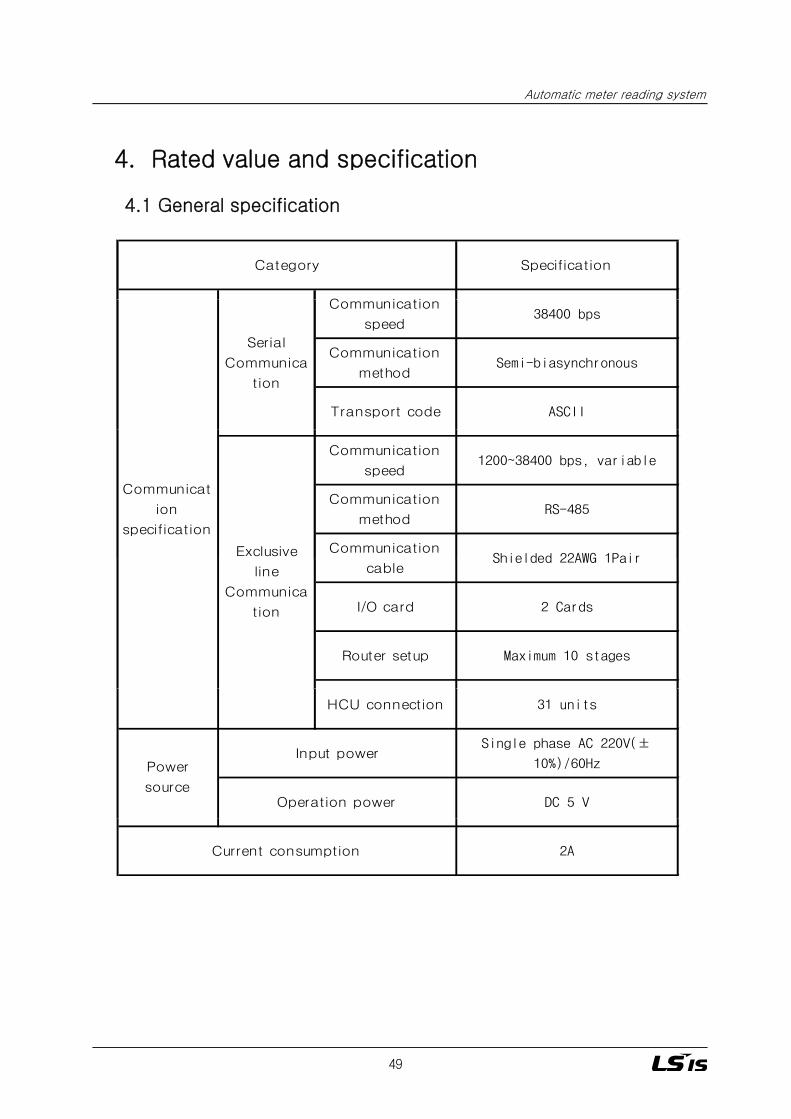
4. Rated value and specification
Automatic meter reading system
Specification
C i ti
Category
4.1 General specification
p
Communication
speed38400 bps
Communication
methodSemi-biasynchronous
Transport code ASCII
Serial
Communica
tion
Communication
speed1200~38400 bps, variable
Communication
methodRS-485
CommunicationShielded 22AWG 1Pair
Communicat
ion
specification
Exclusivecable
Shielded 22AWG 1Pair
I/O card 2 Cards
Router setup Maximum 10 stages
line
Communica
tion
HCU connection 31 units
Single phase AC 220V(±
10%)/60Hz
DC 5 VOperation power
Power
source
Input power
2ACurrent consumption
49

5. Communication specification
5.1 Communication specification between the meter reading PCand the CCU
- Communication method: RS-232
- Communication speed: 38400 bpsCommunication speed 38400 bps
- Communication distance: Below 10m
5.2 Communication specification between CCU and HCU
- Communication method: RS-485
- Communication speed: 1200bps ~ 38400bps variableCommunication speed: 1200bps 38400bps, variable
- Communication distance :1.2Km (Maximum extension of 13.2Km if
router is used)
- Connection method: 2 Wire Multi – drop.
6. Wiring method and precautions
- Use shielded Twisted Pair Cable.
- Recommended Cable: LIREV AMESB 22AWG made by LS Cable
- Pay attention to color when performing the communication cable wiring.
백색White
청색Blue
50

V. HCU LOADER
51

1. LOADER overview
Automatic meter reading system
1.1 Overview
HCU Loader is a portable device that is used in conjunction with the HCU (Home Control Unit). After installation of the HCU, the device is used to input various data of HCU.
1.2 Purpose
■ Input of HCU ID
■ Input of HCU Version and Data and Date■ Input of HCU Version and Data and Date
■ Input of HCU communication baud rate
■ Input of meter type and meter pulse specification connected to the HCU
■ Input of each port meter usage connected to the HCU
■ Display setting of meter usage such as decimal places and units
1.3 HCU Loader appearance
LCD
■ KEY description
KEY pad
(Total 17 keys)
KEY Description
0~9 Data input
Cancel Return to previous screen
Run Run a command
↔ Page left, right
↑↓ Page up down
52
↑↓ Page up, down
Reset Initialize program

2. LOADER user guide
2.1 Initial screen of the loader
■ If cover of the HCU is removed and the HCU loader is connected to the loader communication connector, the load will display as follows.
Down load HCU ID<< HCU LOADER >>LSIS ( Ver 4.2 )
Down load HCU ID----- Rxing -----1st Comm End10 Success
Initial message
(Displayed for 1 sec)
> Select Menu :4 Meter Setting
> Select Menu : 1. HCU ID Setting2. Write Version3. COM Speed Setting
Menu selection screen
4. Meter Setting5. Meter Value6. Disp Decimal
> Select Menu :7. Meter Pre-Set. 8. Meter Set Port.9 All Meter SET
■ Input menu description
9. All Meter SET.
> Select Menu :10. Pulse Pmt.11. Monitoring.
■ Input menu description
‘1’ : Input of HCU ID
‘2’ : Input of HCU Version
‘3’ : Input of HCU communication baud rate
‘4’ : Input of Meter Setting, parameter and pulse time
‘5’ : Input of current meter usage in the HCU
‘6’ : Display setting of HCU such as decimal places and units.
53
‘7’ : Input and storage of batch setting data (Pre-set function).
‘8’ : Batch input with the setting data saved in ‘7’.
‘9’ : Same function as ‘8’ (However, if you press ‘Run’, it will move to the input screen for the next port).
‘10’: Input of instrument constant(Pulse Parameter) of each port.
’11’: Not used.

2.2 HCU ID input
Automatic meter reading system
■ Inputs ID in the HCU. HCU ID installed in the same CCU location should not be overlapped.
NO KEY operation LCD status Remark
> Select Menu :Key No. 1 > Select Menu :
1.HCU ID Setting
HCU ID Setting
ID :
HCU ID Setting In case the HCU ID is 10001
ID : 10001 Press ‘←’ (B ck Sp ce) ke for correction
1 Menu selection screen appears.
2 Input of IDPress ‘Cancel’ KEY to return to the previousscreen
y+'Run'
3 ‘10001’ + ‘Run’ ID : 10001 Press ← (Back Space) key for correction
> Select Menu :
1.HCU ID Setting4 Return to the main menu selection screen.
2.3 Input of HCU Version and date
■ HCU Version is entered as the product is shipped. The Version and date is used for later version upgrade. For accurate version management, the user should never modify the version and date.
NO KEY operation LCD status Remark
> Select Menu :
2.Write Version
HCU Version
1Key No. 2
+'Run' Menu selection screen appears.
2Press ‘Cancel’ KEY to return to the previous Enter S/W, H/W and
modified date S/W Ver :
H/W Ver :
Date :
> Select Menu :
2.Write Version
Press ‘←’ (Back Space) key for correction
4 Return to the main menu selection screen.
2screenmodified date
+'Run'
3
54

2.4 Input of the HCU communication baud rate
■ The system is designed in a way that the HCU communicates the meter reading PC through
the routing function of the CCU. At this time, the communication speed needs to match in order for the communication to work. Therefore, this is used to input the accurate communication speed into the HCU.
NO KEY operation LCD status Remark
> Select Menu :
3.COM Speed Setting
> COM Speed :
1. 1200 bps
+ 'Run'
Menu selection screen appears.
2Press ‘Cancel’ KEY to return to the previousscreen
3 Press ‘←’ (Back Space) key for correction
Input of COM Speed
1Key No. 3
+'Run'
∼∼
2.5 Input of the Meter Setting
■ C fi t t th t t d t th HCU l ti f th
6. 38400 bps
> Select Menu :
3.COM Speed Setting4 Return to the main menu selection screen.
■ Configures meter type that are connected to the HCU, pulse time of the metering pulse, data display type of the meter reading data stored in the HCU.
Caution : ‘4’ Meter Setting Input process needs to be performed after ’10’ Pulse Pmt. setting Input is finished. If ‘4’ Meter Setting Input is performed first and then ’10’Pulse Pmt. setting Input is performed, meter reading data that are stored in the HCU are internally calculated again using the Pulse Parameter(instrument constant)Pulse Parameter(instrument constant).
NO KEY operation LCD status Remark
> Select Menu :
4.Meter Setting
S l P 1
1Key No. 4
+'Run' Menu selection screen appears.
Port setting of HCU > Select Port : 1
1. Port ~ 6.Port
1P WHM Set : 1
Parmeter : 6/3
Pulse Time : 0005
1'+'6/0'+'0005'+'Run'3In case the type of the meter is electricity,the Pulse Parmeter (instrument constant)is1000 and the Pulse Time is 5ms.
2Port setting of HCU
(No. 1)+ 'Run'
Enter the port number of the HCU to input(1~6).
55
> Select Port :
1. Port ~ 6.Port
5 Repeat 2~4 until port 6.
'Run' or 'Cancel'4 Return to the main menu selection screen.

■ Type of meter and how to setup parameter (example)
( )
Automatic meter reading system
Parameter setup
1 Electricity 6/0
2 Gas 6/1
3 Water 6/2
4 Hot-water 6/3 1000 (1000 pulse/1㎥)
Pulse Parmeter(instrument constant)specification
Category of meter
1 (1 pulse/1kWh)
10 (10 pulse/1㎥)
100 (100 pulse/1㎥)
2.6 Input of meter usage
■ Used to enter usage of each port meter connected to HCU into the HCU.
5 Calorie 6/3 500 (500 pulse/1MWh)
■ Used to enter usage of each port meter connected to HCU into the HCU.
NO KEY operation LCD status Remark
> Select Menu :
5.Meter Value
> Value Port :
1Key No. 5
+'Run' Menu selection screen appears.
HCU Port (No. 1)( )
1. Port ~ 6.Port
> Input Value
Value : 001111
> Value Port :
1 Port ~ 6 Port
2 +'Run' Enter meter usage by port (1~6).
'001111'+'Run'3 In case the meter usage is '001111'
4 Run' or 'Cancel' Return to the main menu selection screen.
■ Example of meter usage input
- If the meter type is electricity meter and current total usage is ‘123’KWh
1. Port 6.Port
5 Repeat 2~4 until port 6.
: ‘000123.000’ (Parameter is entered 6/0 so that digits below the decimal point will not be displayed.)
- If the meter type is gas, water, hot-water meter and pulse specification is 1000pulse/1㎥ and current total usage is ‘123.456’ ㎥
: ‘000123.456’ (Parameter is entered 6/3 so that three digits below the decimal point will be displayed )
56
decimal point will be displayed.)

2.8 Batch storage of setting DATA (Pre-set function).
■ The following four setting data can be stored in this menu: Meter type of each port, Parameter (display specification), Pulse Time (time interval of the metering pulse), Pulse Parameter(instrument constant).
NO KEY operation LCD status Remark
> Select Menu :Key No. 7 > Select Menu :
7.Meter Pre-Set
NEW HCU (Y/N?)
'1' YES ==> 1
NO ==> 0
Press [Y/N]
1ey o+'Run' Menu selection screen appears.
Asks if the HCU is the new type.2+ 'Run'
> Select Port :1
1.Port -> 6.Port
1P WMH Set : x
Parameter : x/x
Pulse Time : xxxx
> Input Pulse Pmt
'Run' or 'Cancel'4 Enter corresponding values.
3 'Run' or 'Cancel' Displays that the port No. 1 is selected.
> Input Pulse Pmt.
xxxxx
> Select Port :2
1.Port -> 6.Port
'Run' or 'Cancel'
'Run' or 'Cancel'
5
6
Enter the desired Pulse Parameter value
Enter Port1 through Port6 in the same procedure as No. 3.
57

2.9 Batch input of setting DATA (All Meter SET function).
Automatic meter reading system
NO KEY operation LCD status Remark
■ In this menu, setting data stored in 2.8 can be called back to setup the four setting data i.e. the meter type of each port, Parameter (display specification), Pulse Time (time interval of the metering pulse), Pulse Parameter(instrument constant) in one stroke by port.
> Select Menu :
9.All Meter SET
Meter Pre-Set
Value Port 1->6
>Input Pulse Pmt.
1Key No. 9
+'Run' Menu selection screen appears.
'Run' or 'Cancel'2
Pulse Parameter
Port #1 xxxxx
1P WMH Set : x
Prameter:x/x
Pulse Time:xxxx
3
4 'Run' or 'Cancel' Enter corresponding values.
Enter the corresponding Pulse Parametervalue
'Run' or 'Cancel'
>Input Value
>Input Pulse Pmt.
Pulse Parameter
P t #2
6Enter Port2 through Port6 in the sameprocedure as No. 3.
'Run' or 'Cancel'
'Run' or 'Cancel'5 Enter metered values. Value:xxxxxx .xxx
Port #2 xxxxx
58

2.10 Pulse Parameter (instrument constant) input
/■ Input of PULSE/Unit usage for each port meter connected to the HCU..
NO KEY operation LCD status Remark
> Select Menu :
10.Pulse Pmt.
' '
1KEY No. 10
+ 'Run' Show menu selection screen.
'Cancel'or >Select Port :
PORT No. + 'Run' 1.Port -> 6.Port
Run' or 'Cancel' > Input Pulse Pmt
Pulse Parameter
xxxxx
Port selection.2
3 Corresponding Pulse Parameter input.
2.11 Setup data input procedure
■ Input Pulse Parameter (instrument constant)I M V l ( ) I M S i
3. Precautions during use of HCU Loader
-> Input Meter Value (meter usage) -> Input Meter Setting
■ Do not drop the loader on the ground during operation or moving.
■ Do not apply too much force when operating the keys.
■ Check the date on the LCD during input in order to prevent input errors.
■ Use caution to avoid electric damage when connecting signal cables to the HCU.
59

2011. 08 Automatic Meter Reading Systems Manual (E) 2011. 08/(01) 2011. 08. STAFF
www.lsis.biz
ⓒ 2011.8 LSIS Co.,Ltd. All rights reserved.
�For your safety, please read user's manual thoroughly before operating.
�Contact the nearest authorized service facility for examination, repair, or adjustment.
�Please contact qualified service technician when you need maintenance.Do not disassemble or repair by yourself!
�Any maintenance and inspection shall be performed by the personnel having expertise concerned.Safety Instructions
�LSIS (Middle East) FZE ��Dubai, U.A.E. Address: LOB 19 JAFZA VIEW TOWER Room 205, Jebel Ali Freezone P.O. Box 114216, Dubai, United Arab EmiratesTel: 971-4-886 5360 Fax: 971-4-886-5361 e-mail: [email protected] �Dalian LSIS Co., Ltd. ��Dalian, China
Address: No.15, Liaohexi 3-Road, Economic and Technical Development zone, Dalian 116600, ChinaTel: 86-411-8273-7777 Fax: 86-411-8730-7560 e-mail: [email protected]�LSIS (Wuxi) Co., Ltd. ��Wuxi, China
Address: 102-A , National High & New Tech Industrial Development Area, Wuxi, Jiangsu, 214028, P.R.ChinaTel: 86-510-8534-6666 Fax: 86-510-522-4078 e-mail: [email protected]�LSIS-VINA Co., Ltd. ��Hanoi, Vietnam
Address: Nguyen Khe - Dong Anh - Ha Noi - Viet NamTel: 84-4-882-0222 Fax: 84-4-882-0220 e-mail: [email protected]�LSIS-VINA Co., Ltd. ��Hochiminh , Vietnam
Address: 41 Nguyen Thi Minh Khai Str. Yoco Bldg 4th Floor, Hochiminh City, VietnamTel: 84-8-3822-7941 Fax: 84-8-3822-7942 e-mail: [email protected]�LSIS Shanghai Office ��Shanghai, China
Address: Room E-G, 12th Floor Huamin Empire Plaza, No.726, West Yan'an Road Shanghai 200050, P.R. ChinaTel: 86-21-5237-9977 (609) Fax: 89-21-5237-7191 e-mail: [email protected]�LSIS Beijing Office ��Beijing, China
Address: B-Tower 17FL.Beijing Global Trade Center B/D. No.36, BeiSanHuanDong-Lu, DongCheng-District,Beijing 100013, P.R. ChinaTel: 86-10-5825-6025,7 Fax: 86-10-5825-6026 e-mail: [email protected]�LSIS Guangzhou Office ��Guangzhou, China
Address: Room 1403,14F,New Poly Tower,2 Zhongshan Liu Road,Guangzhou, P.R. ChinaTel: 86-20-8326-6764 Fax: 86-20-8326-6287 e-mail: [email protected]�LSIS Chengdu Office ��Chengdu, China
Address: Room 1701 17Floor, huanminhanjun internationnal Building, No1 Fuxing Road Chengdu, 610041, P.R. ChinaTel: 86-28-8670-3101 Fax: 86-28-8670-3203 e-mail: [email protected]�LSIS Qingdao Office ��Qingdao, China
Address: 7B40,Haixin Guangchang Shenye Building B, No.9, Shandong Road Qingdao 26600, P.R. ChinaTel: 86-532-8501-6568 Fax: 86-532-583-3793 e-mail: [email protected]�LSIS NETHERLANDS Co.Ltd ��Netherlands
Address: 1st. Floor, Tupolevlaan 48, 1119NZ,Schiphol-Rijk, The NetherlandsTel: 31-20-654-1420 Fax: 31-20-654-1429 e-mail: [email protected]�LSIS Gurgaon Office ��Gurgaon ,India
Address: 109 First Floor, Park Central, Sector-30, Gurgaon- 122 002, Haryana, India
� HEAD OFFICEKorea Gyeonggi-do Anyang-si dongan-gu LS-ro 127 (Hogye-dong) Tel. (82-2)2034-4887, 4873, 4918, 4148Fax. (82-2)2034-4648
� CHEONG-JU PLANTCheong-Ju Plant #1, Song Jung Dong, Hung Duk Ku,Cheong Ju, 361-720, Korea
�Global Network
Specifications in this catalog are subject to change without notice due to continuous product development and improvement.