manual caldera.pdf
TRANSCRIPT

8/11/2019 Manual Caldera.pdf
http://slidepdf.com/reader/full/manual-calderapdf 1/838

8/11/2019 Manual Caldera.pdf
http://slidepdf.com/reader/full/manual-calderapdf 2/838

8/11/2019 Manual Caldera.pdf
http://slidepdf.com/reader/full/manual-calderapdf 3/838

8/11/2019 Manual Caldera.pdf
http://slidepdf.com/reader/full/manual-calderapdf 4/838
8/11/2019 Manual Caldera.pdf
http://slidepdf.com/reader/full/manual-calderapdf 5/838

8/11/2019 Manual Caldera.pdf
http://slidepdf.com/reader/full/manual-calderapdf 6/838

8/11/2019 Manual Caldera.pdf
http://slidepdf.com/reader/full/manual-calderapdf 7/838

8/11/2019 Manual Caldera.pdf
http://slidepdf.com/reader/full/manual-calderapdf 8/838

8/11/2019 Manual Caldera.pdf
http://slidepdf.com/reader/full/manual-calderapdf 9/838

8/11/2019 Manual Caldera.pdf
http://slidepdf.com/reader/full/manual-calderapdf 10/838

8/11/2019 Manual Caldera.pdf
http://slidepdf.com/reader/full/manual-calderapdf 11/838

8/11/2019 Manual Caldera.pdf
http://slidepdf.com/reader/full/manual-calderapdf 12/838

8/11/2019 Manual Caldera.pdf
http://slidepdf.com/reader/full/manual-calderapdf 13/838

8/11/2019 Manual Caldera.pdf
http://slidepdf.com/reader/full/manual-calderapdf 14/838

8/11/2019 Manual Caldera.pdf
http://slidepdf.com/reader/full/manual-calderapdf 15/838

8/11/2019 Manual Caldera.pdf
http://slidepdf.com/reader/full/manual-calderapdf 16/838

8/11/2019 Manual Caldera.pdf
http://slidepdf.com/reader/full/manual-calderapdf 17/838

8/11/2019 Manual Caldera.pdf
http://slidepdf.com/reader/full/manual-calderapdf 18/838

8/11/2019 Manual Caldera.pdf
http://slidepdf.com/reader/full/manual-calderapdf 19/838

8/11/2019 Manual Caldera.pdf
http://slidepdf.com/reader/full/manual-calderapdf 20/838

8/11/2019 Manual Caldera.pdf
http://slidepdf.com/reader/full/manual-calderapdf 21/838

8/11/2019 Manual Caldera.pdf
http://slidepdf.com/reader/full/manual-calderapdf 22/838

8/11/2019 Manual Caldera.pdf
http://slidepdf.com/reader/full/manual-calderapdf 23/838

8/11/2019 Manual Caldera.pdf
http://slidepdf.com/reader/full/manual-calderapdf 24/838

8/11/2019 Manual Caldera.pdf
http://slidepdf.com/reader/full/manual-calderapdf 25/838

8/11/2019 Manual Caldera.pdf
http://slidepdf.com/reader/full/manual-calderapdf 26/838

8/11/2019 Manual Caldera.pdf
http://slidepdf.com/reader/full/manual-calderapdf 27/838

8/11/2019 Manual Caldera.pdf
http://slidepdf.com/reader/full/manual-calderapdf 28/838

8/11/2019 Manual Caldera.pdf
http://slidepdf.com/reader/full/manual-calderapdf 29/838

8/11/2019 Manual Caldera.pdf
http://slidepdf.com/reader/full/manual-calderapdf 30/838

8/11/2019 Manual Caldera.pdf
http://slidepdf.com/reader/full/manual-calderapdf 31/838

8/11/2019 Manual Caldera.pdf
http://slidepdf.com/reader/full/manual-calderapdf 32/838

8/11/2019 Manual Caldera.pdf
http://slidepdf.com/reader/full/manual-calderapdf 33/838

8/11/2019 Manual Caldera.pdf
http://slidepdf.com/reader/full/manual-calderapdf 34/838

8/11/2019 Manual Caldera.pdf
http://slidepdf.com/reader/full/manual-calderapdf 35/838

8/11/2019 Manual Caldera.pdf
http://slidepdf.com/reader/full/manual-calderapdf 36/838

8/11/2019 Manual Caldera.pdf
http://slidepdf.com/reader/full/manual-calderapdf 37/838

8/11/2019 Manual Caldera.pdf
http://slidepdf.com/reader/full/manual-calderapdf 38/838

8/11/2019 Manual Caldera.pdf
http://slidepdf.com/reader/full/manual-calderapdf 39/838

8/11/2019 Manual Caldera.pdf
http://slidepdf.com/reader/full/manual-calderapdf 40/838

8/11/2019 Manual Caldera.pdf
http://slidepdf.com/reader/full/manual-calderapdf 41/838

8/11/2019 Manual Caldera.pdf
http://slidepdf.com/reader/full/manual-calderapdf 42/838

8/11/2019 Manual Caldera.pdf
http://slidepdf.com/reader/full/manual-calderapdf 43/838

8/11/2019 Manual Caldera.pdf
http://slidepdf.com/reader/full/manual-calderapdf 44/838

8/11/2019 Manual Caldera.pdf
http://slidepdf.com/reader/full/manual-calderapdf 45/838

8/11/2019 Manual Caldera.pdf
http://slidepdf.com/reader/full/manual-calderapdf 46/838

8/11/2019 Manual Caldera.pdf
http://slidepdf.com/reader/full/manual-calderapdf 47/838

8/11/2019 Manual Caldera.pdf
http://slidepdf.com/reader/full/manual-calderapdf 48/838

8/11/2019 Manual Caldera.pdf
http://slidepdf.com/reader/full/manual-calderapdf 49/838

8/11/2019 Manual Caldera.pdf
http://slidepdf.com/reader/full/manual-calderapdf 50/838

8/11/2019 Manual Caldera.pdf
http://slidepdf.com/reader/full/manual-calderapdf 51/838

8/11/2019 Manual Caldera.pdf
http://slidepdf.com/reader/full/manual-calderapdf 52/838

8/11/2019 Manual Caldera.pdf
http://slidepdf.com/reader/full/manual-calderapdf 53/838

8/11/2019 Manual Caldera.pdf
http://slidepdf.com/reader/full/manual-calderapdf 54/838

8/11/2019 Manual Caldera.pdf
http://slidepdf.com/reader/full/manual-calderapdf 55/838

8/11/2019 Manual Caldera.pdf
http://slidepdf.com/reader/full/manual-calderapdf 56/838

8/11/2019 Manual Caldera.pdf
http://slidepdf.com/reader/full/manual-calderapdf 57/838

8/11/2019 Manual Caldera.pdf
http://slidepdf.com/reader/full/manual-calderapdf 58/838

8/11/2019 Manual Caldera.pdf
http://slidepdf.com/reader/full/manual-calderapdf 59/838

8/11/2019 Manual Caldera.pdf
http://slidepdf.com/reader/full/manual-calderapdf 60/838

8/11/2019 Manual Caldera.pdf
http://slidepdf.com/reader/full/manual-calderapdf 61/838

8/11/2019 Manual Caldera.pdf
http://slidepdf.com/reader/full/manual-calderapdf 62/838

8/11/2019 Manual Caldera.pdf
http://slidepdf.com/reader/full/manual-calderapdf 63/838

8/11/2019 Manual Caldera.pdf
http://slidepdf.com/reader/full/manual-calderapdf 64/838

8/11/2019 Manual Caldera.pdf
http://slidepdf.com/reader/full/manual-calderapdf 65/838

8/11/2019 Manual Caldera.pdf
http://slidepdf.com/reader/full/manual-calderapdf 66/838

8/11/2019 Manual Caldera.pdf
http://slidepdf.com/reader/full/manual-calderapdf 67/838

8/11/2019 Manual Caldera.pdf
http://slidepdf.com/reader/full/manual-calderapdf 68/838

8/11/2019 Manual Caldera.pdf
http://slidepdf.com/reader/full/manual-calderapdf 69/838

8/11/2019 Manual Caldera.pdf
http://slidepdf.com/reader/full/manual-calderapdf 70/838

8/11/2019 Manual Caldera.pdf
http://slidepdf.com/reader/full/manual-calderapdf 71/838

8/11/2019 Manual Caldera.pdf
http://slidepdf.com/reader/full/manual-calderapdf 72/838

8/11/2019 Manual Caldera.pdf
http://slidepdf.com/reader/full/manual-calderapdf 73/838

8/11/2019 Manual Caldera.pdf
http://slidepdf.com/reader/full/manual-calderapdf 74/838

8/11/2019 Manual Caldera.pdf
http://slidepdf.com/reader/full/manual-calderapdf 75/838

8/11/2019 Manual Caldera.pdf
http://slidepdf.com/reader/full/manual-calderapdf 76/838

8/11/2019 Manual Caldera.pdf
http://slidepdf.com/reader/full/manual-calderapdf 77/838

8/11/2019 Manual Caldera.pdf
http://slidepdf.com/reader/full/manual-calderapdf 78/838

8/11/2019 Manual Caldera.pdf
http://slidepdf.com/reader/full/manual-calderapdf 79/838

8/11/2019 Manual Caldera.pdf
http://slidepdf.com/reader/full/manual-calderapdf 80/838

8/11/2019 Manual Caldera.pdf
http://slidepdf.com/reader/full/manual-calderapdf 81/838

8/11/2019 Manual Caldera.pdf
http://slidepdf.com/reader/full/manual-calderapdf 82/838

8/11/2019 Manual Caldera.pdf
http://slidepdf.com/reader/full/manual-calderapdf 83/838

8/11/2019 Manual Caldera.pdf
http://slidepdf.com/reader/full/manual-calderapdf 84/838

8/11/2019 Manual Caldera.pdf
http://slidepdf.com/reader/full/manual-calderapdf 85/838

8/11/2019 Manual Caldera.pdf
http://slidepdf.com/reader/full/manual-calderapdf 86/838

8/11/2019 Manual Caldera.pdf
http://slidepdf.com/reader/full/manual-calderapdf 87/838

8/11/2019 Manual Caldera.pdf
http://slidepdf.com/reader/full/manual-calderapdf 88/838

8/11/2019 Manual Caldera.pdf
http://slidepdf.com/reader/full/manual-calderapdf 89/838

8/11/2019 Manual Caldera.pdf
http://slidepdf.com/reader/full/manual-calderapdf 90/838

8/11/2019 Manual Caldera.pdf
http://slidepdf.com/reader/full/manual-calderapdf 91/838

8/11/2019 Manual Caldera.pdf
http://slidepdf.com/reader/full/manual-calderapdf 92/838

8/11/2019 Manual Caldera.pdf
http://slidepdf.com/reader/full/manual-calderapdf 93/838

8/11/2019 Manual Caldera.pdf
http://slidepdf.com/reader/full/manual-calderapdf 94/838

8/11/2019 Manual Caldera.pdf
http://slidepdf.com/reader/full/manual-calderapdf 95/838

8/11/2019 Manual Caldera.pdf
http://slidepdf.com/reader/full/manual-calderapdf 96/838

8/11/2019 Manual Caldera.pdf
http://slidepdf.com/reader/full/manual-calderapdf 97/838

8/11/2019 Manual Caldera.pdf
http://slidepdf.com/reader/full/manual-calderapdf 98/838

8/11/2019 Manual Caldera.pdf
http://slidepdf.com/reader/full/manual-calderapdf 99/838

8/11/2019 Manual Caldera.pdf
http://slidepdf.com/reader/full/manual-calderapdf 100/838

8/11/2019 Manual Caldera.pdf
http://slidepdf.com/reader/full/manual-calderapdf 101/838

8/11/2019 Manual Caldera.pdf
http://slidepdf.com/reader/full/manual-calderapdf 102/838

8/11/2019 Manual Caldera.pdf
http://slidepdf.com/reader/full/manual-calderapdf 103/838

8/11/2019 Manual Caldera.pdf
http://slidepdf.com/reader/full/manual-calderapdf 104/838

8/11/2019 Manual Caldera.pdf
http://slidepdf.com/reader/full/manual-calderapdf 105/838

8/11/2019 Manual Caldera.pdf
http://slidepdf.com/reader/full/manual-calderapdf 106/838

8/11/2019 Manual Caldera.pdf
http://slidepdf.com/reader/full/manual-calderapdf 107/838

8/11/2019 Manual Caldera.pdf
http://slidepdf.com/reader/full/manual-calderapdf 108/838

8/11/2019 Manual Caldera.pdf
http://slidepdf.com/reader/full/manual-calderapdf 109/838

8/11/2019 Manual Caldera.pdf
http://slidepdf.com/reader/full/manual-calderapdf 110/838

8/11/2019 Manual Caldera.pdf
http://slidepdf.com/reader/full/manual-calderapdf 111/838

8/11/2019 Manual Caldera.pdf
http://slidepdf.com/reader/full/manual-calderapdf 112/838

8/11/2019 Manual Caldera.pdf
http://slidepdf.com/reader/full/manual-calderapdf 113/838

8/11/2019 Manual Caldera.pdf
http://slidepdf.com/reader/full/manual-calderapdf 114/838

8/11/2019 Manual Caldera.pdf
http://slidepdf.com/reader/full/manual-calderapdf 115/838

8/11/2019 Manual Caldera.pdf
http://slidepdf.com/reader/full/manual-calderapdf 116/838

8/11/2019 Manual Caldera.pdf
http://slidepdf.com/reader/full/manual-calderapdf 117/838

8/11/2019 Manual Caldera.pdf
http://slidepdf.com/reader/full/manual-calderapdf 118/838

8/11/2019 Manual Caldera.pdf
http://slidepdf.com/reader/full/manual-calderapdf 119/838

8/11/2019 Manual Caldera.pdf
http://slidepdf.com/reader/full/manual-calderapdf 120/838

8/11/2019 Manual Caldera.pdf
http://slidepdf.com/reader/full/manual-calderapdf 121/838

8/11/2019 Manual Caldera.pdf
http://slidepdf.com/reader/full/manual-calderapdf 122/838

8/11/2019 Manual Caldera.pdf
http://slidepdf.com/reader/full/manual-calderapdf 123/838

8/11/2019 Manual Caldera.pdf
http://slidepdf.com/reader/full/manual-calderapdf 124/838

8/11/2019 Manual Caldera.pdf
http://slidepdf.com/reader/full/manual-calderapdf 125/838

8/11/2019 Manual Caldera.pdf
http://slidepdf.com/reader/full/manual-calderapdf 126/838

8/11/2019 Manual Caldera.pdf
http://slidepdf.com/reader/full/manual-calderapdf 127/838

8/11/2019 Manual Caldera.pdf
http://slidepdf.com/reader/full/manual-calderapdf 128/838

8/11/2019 Manual Caldera.pdf
http://slidepdf.com/reader/full/manual-calderapdf 129/838

8/11/2019 Manual Caldera.pdf
http://slidepdf.com/reader/full/manual-calderapdf 130/838

8/11/2019 Manual Caldera.pdf
http://slidepdf.com/reader/full/manual-calderapdf 131/838

8/11/2019 Manual Caldera.pdf
http://slidepdf.com/reader/full/manual-calderapdf 132/838

8/11/2019 Manual Caldera.pdf
http://slidepdf.com/reader/full/manual-calderapdf 133/838

8/11/2019 Manual Caldera.pdf
http://slidepdf.com/reader/full/manual-calderapdf 134/838

8/11/2019 Manual Caldera.pdf
http://slidepdf.com/reader/full/manual-calderapdf 135/838

8/11/2019 Manual Caldera.pdf
http://slidepdf.com/reader/full/manual-calderapdf 136/838

8/11/2019 Manual Caldera.pdf
http://slidepdf.com/reader/full/manual-calderapdf 137/838

8/11/2019 Manual Caldera.pdf
http://slidepdf.com/reader/full/manual-calderapdf 138/838

8/11/2019 Manual Caldera.pdf
http://slidepdf.com/reader/full/manual-calderapdf 139/838

8/11/2019 Manual Caldera.pdf
http://slidepdf.com/reader/full/manual-calderapdf 140/838

8/11/2019 Manual Caldera.pdf
http://slidepdf.com/reader/full/manual-calderapdf 141/838

8/11/2019 Manual Caldera.pdf
http://slidepdf.com/reader/full/manual-calderapdf 142/838

8/11/2019 Manual Caldera.pdf
http://slidepdf.com/reader/full/manual-calderapdf 143/838

8/11/2019 Manual Caldera.pdf
http://slidepdf.com/reader/full/manual-calderapdf 144/838

8/11/2019 Manual Caldera.pdf
http://slidepdf.com/reader/full/manual-calderapdf 145/838

8/11/2019 Manual Caldera.pdf
http://slidepdf.com/reader/full/manual-calderapdf 146/838

8/11/2019 Manual Caldera.pdf
http://slidepdf.com/reader/full/manual-calderapdf 147/838

8/11/2019 Manual Caldera.pdf
http://slidepdf.com/reader/full/manual-calderapdf 148/838

8/11/2019 Manual Caldera.pdf
http://slidepdf.com/reader/full/manual-calderapdf 149/838

8/11/2019 Manual Caldera.pdf
http://slidepdf.com/reader/full/manual-calderapdf 150/838

8/11/2019 Manual Caldera.pdf
http://slidepdf.com/reader/full/manual-calderapdf 151/838

8/11/2019 Manual Caldera.pdf
http://slidepdf.com/reader/full/manual-calderapdf 152/838

8/11/2019 Manual Caldera.pdf
http://slidepdf.com/reader/full/manual-calderapdf 153/838

8/11/2019 Manual Caldera.pdf
http://slidepdf.com/reader/full/manual-calderapdf 154/838

8/11/2019 Manual Caldera.pdf
http://slidepdf.com/reader/full/manual-calderapdf 155/838

8/11/2019 Manual Caldera.pdf
http://slidepdf.com/reader/full/manual-calderapdf 156/838

8/11/2019 Manual Caldera.pdf
http://slidepdf.com/reader/full/manual-calderapdf 157/838

8/11/2019 Manual Caldera.pdf
http://slidepdf.com/reader/full/manual-calderapdf 158/838

8/11/2019 Manual Caldera.pdf
http://slidepdf.com/reader/full/manual-calderapdf 159/838

8/11/2019 Manual Caldera.pdf
http://slidepdf.com/reader/full/manual-calderapdf 160/838

8/11/2019 Manual Caldera.pdf
http://slidepdf.com/reader/full/manual-calderapdf 161/838

8/11/2019 Manual Caldera.pdf
http://slidepdf.com/reader/full/manual-calderapdf 162/838

8/11/2019 Manual Caldera.pdf
http://slidepdf.com/reader/full/manual-calderapdf 163/838

8/11/2019 Manual Caldera.pdf
http://slidepdf.com/reader/full/manual-calderapdf 164/838

8/11/2019 Manual Caldera.pdf
http://slidepdf.com/reader/full/manual-calderapdf 165/838

8/11/2019 Manual Caldera.pdf
http://slidepdf.com/reader/full/manual-calderapdf 166/838

8/11/2019 Manual Caldera.pdf
http://slidepdf.com/reader/full/manual-calderapdf 167/838

8/11/2019 Manual Caldera.pdf
http://slidepdf.com/reader/full/manual-calderapdf 168/838

8/11/2019 Manual Caldera.pdf
http://slidepdf.com/reader/full/manual-calderapdf 169/838

8/11/2019 Manual Caldera.pdf
http://slidepdf.com/reader/full/manual-calderapdf 170/838

8/11/2019 Manual Caldera.pdf
http://slidepdf.com/reader/full/manual-calderapdf 171/838

8/11/2019 Manual Caldera.pdf
http://slidepdf.com/reader/full/manual-calderapdf 172/838

8/11/2019 Manual Caldera.pdf
http://slidepdf.com/reader/full/manual-calderapdf 173/838

8/11/2019 Manual Caldera.pdf
http://slidepdf.com/reader/full/manual-calderapdf 174/838

8/11/2019 Manual Caldera.pdf
http://slidepdf.com/reader/full/manual-calderapdf 175/838

8/11/2019 Manual Caldera.pdf
http://slidepdf.com/reader/full/manual-calderapdf 176/838

8/11/2019 Manual Caldera.pdf
http://slidepdf.com/reader/full/manual-calderapdf 177/838

8/11/2019 Manual Caldera.pdf
http://slidepdf.com/reader/full/manual-calderapdf 178/838

8/11/2019 Manual Caldera.pdf
http://slidepdf.com/reader/full/manual-calderapdf 179/838

8/11/2019 Manual Caldera.pdf
http://slidepdf.com/reader/full/manual-calderapdf 180/838

8/11/2019 Manual Caldera.pdf
http://slidepdf.com/reader/full/manual-calderapdf 181/838

8/11/2019 Manual Caldera.pdf
http://slidepdf.com/reader/full/manual-calderapdf 182/838

8/11/2019 Manual Caldera.pdf
http://slidepdf.com/reader/full/manual-calderapdf 183/838

8/11/2019 Manual Caldera.pdf
http://slidepdf.com/reader/full/manual-calderapdf 184/838

8/11/2019 Manual Caldera.pdf
http://slidepdf.com/reader/full/manual-calderapdf 185/838

8/11/2019 Manual Caldera.pdf
http://slidepdf.com/reader/full/manual-calderapdf 186/838

8/11/2019 Manual Caldera.pdf
http://slidepdf.com/reader/full/manual-calderapdf 187/838

8/11/2019 Manual Caldera.pdf
http://slidepdf.com/reader/full/manual-calderapdf 188/838

8/11/2019 Manual Caldera.pdf
http://slidepdf.com/reader/full/manual-calderapdf 189/838

8/11/2019 Manual Caldera.pdf
http://slidepdf.com/reader/full/manual-calderapdf 190/838

8/11/2019 Manual Caldera.pdf
http://slidepdf.com/reader/full/manual-calderapdf 191/838

8/11/2019 Manual Caldera.pdf
http://slidepdf.com/reader/full/manual-calderapdf 192/838

8/11/2019 Manual Caldera.pdf
http://slidepdf.com/reader/full/manual-calderapdf 193/838

8/11/2019 Manual Caldera.pdf
http://slidepdf.com/reader/full/manual-calderapdf 194/838

8/11/2019 Manual Caldera.pdf
http://slidepdf.com/reader/full/manual-calderapdf 195/838

8/11/2019 Manual Caldera.pdf
http://slidepdf.com/reader/full/manual-calderapdf 196/838

8/11/2019 Manual Caldera.pdf
http://slidepdf.com/reader/full/manual-calderapdf 197/838

8/11/2019 Manual Caldera.pdf
http://slidepdf.com/reader/full/manual-calderapdf 198/838

8/11/2019 Manual Caldera.pdf
http://slidepdf.com/reader/full/manual-calderapdf 199/838

8/11/2019 Manual Caldera.pdf
http://slidepdf.com/reader/full/manual-calderapdf 200/838

8/11/2019 Manual Caldera.pdf
http://slidepdf.com/reader/full/manual-calderapdf 201/838

8/11/2019 Manual Caldera.pdf
http://slidepdf.com/reader/full/manual-calderapdf 202/838

8/11/2019 Manual Caldera.pdf
http://slidepdf.com/reader/full/manual-calderapdf 203/838

8/11/2019 Manual Caldera.pdf
http://slidepdf.com/reader/full/manual-calderapdf 204/838

8/11/2019 Manual Caldera.pdf
http://slidepdf.com/reader/full/manual-calderapdf 205/838

8/11/2019 Manual Caldera.pdf
http://slidepdf.com/reader/full/manual-calderapdf 206/838

8/11/2019 Manual Caldera.pdf
http://slidepdf.com/reader/full/manual-calderapdf 207/838

8/11/2019 Manual Caldera.pdf
http://slidepdf.com/reader/full/manual-calderapdf 208/838

8/11/2019 Manual Caldera.pdf
http://slidepdf.com/reader/full/manual-calderapdf 209/838

8/11/2019 Manual Caldera.pdf
http://slidepdf.com/reader/full/manual-calderapdf 210/838

8/11/2019 Manual Caldera.pdf
http://slidepdf.com/reader/full/manual-calderapdf 211/838

8/11/2019 Manual Caldera.pdf
http://slidepdf.com/reader/full/manual-calderapdf 212/838

8/11/2019 Manual Caldera.pdf
http://slidepdf.com/reader/full/manual-calderapdf 213/838

8/11/2019 Manual Caldera.pdf
http://slidepdf.com/reader/full/manual-calderapdf 214/838

8/11/2019 Manual Caldera.pdf
http://slidepdf.com/reader/full/manual-calderapdf 215/838

8/11/2019 Manual Caldera.pdf
http://slidepdf.com/reader/full/manual-calderapdf 216/838

8/11/2019 Manual Caldera.pdf
http://slidepdf.com/reader/full/manual-calderapdf 217/838

8/11/2019 Manual Caldera.pdf
http://slidepdf.com/reader/full/manual-calderapdf 218/838

8/11/2019 Manual Caldera.pdf
http://slidepdf.com/reader/full/manual-calderapdf 219/838

8/11/2019 Manual Caldera.pdf
http://slidepdf.com/reader/full/manual-calderapdf 220/838

8/11/2019 Manual Caldera.pdf
http://slidepdf.com/reader/full/manual-calderapdf 221/838

8/11/2019 Manual Caldera.pdf
http://slidepdf.com/reader/full/manual-calderapdf 222/838

8/11/2019 Manual Caldera.pdf
http://slidepdf.com/reader/full/manual-calderapdf 223/838

8/11/2019 Manual Caldera.pdf
http://slidepdf.com/reader/full/manual-calderapdf 224/838

8/11/2019 Manual Caldera.pdf
http://slidepdf.com/reader/full/manual-calderapdf 225/838

8/11/2019 Manual Caldera.pdf
http://slidepdf.com/reader/full/manual-calderapdf 226/838

8/11/2019 Manual Caldera.pdf
http://slidepdf.com/reader/full/manual-calderapdf 227/838

8/11/2019 Manual Caldera.pdf
http://slidepdf.com/reader/full/manual-calderapdf 228/838

8/11/2019 Manual Caldera.pdf
http://slidepdf.com/reader/full/manual-calderapdf 229/838

8/11/2019 Manual Caldera.pdf
http://slidepdf.com/reader/full/manual-calderapdf 230/838

8/11/2019 Manual Caldera.pdf
http://slidepdf.com/reader/full/manual-calderapdf 231/838

8/11/2019 Manual Caldera.pdf
http://slidepdf.com/reader/full/manual-calderapdf 232/838

8/11/2019 Manual Caldera.pdf
http://slidepdf.com/reader/full/manual-calderapdf 233/838

8/11/2019 Manual Caldera.pdf
http://slidepdf.com/reader/full/manual-calderapdf 234/838

8/11/2019 Manual Caldera.pdf
http://slidepdf.com/reader/full/manual-calderapdf 235/838

8/11/2019 Manual Caldera.pdf
http://slidepdf.com/reader/full/manual-calderapdf 236/838

8/11/2019 Manual Caldera.pdf
http://slidepdf.com/reader/full/manual-calderapdf 237/838

8/11/2019 Manual Caldera.pdf
http://slidepdf.com/reader/full/manual-calderapdf 238/838

8/11/2019 Manual Caldera.pdf
http://slidepdf.com/reader/full/manual-calderapdf 239/838

8/11/2019 Manual Caldera.pdf
http://slidepdf.com/reader/full/manual-calderapdf 240/838

8/11/2019 Manual Caldera.pdf
http://slidepdf.com/reader/full/manual-calderapdf 241/838

8/11/2019 Manual Caldera.pdf
http://slidepdf.com/reader/full/manual-calderapdf 242/838

8/11/2019 Manual Caldera.pdf
http://slidepdf.com/reader/full/manual-calderapdf 243/838

8/11/2019 Manual Caldera.pdf
http://slidepdf.com/reader/full/manual-calderapdf 244/838

8/11/2019 Manual Caldera.pdf
http://slidepdf.com/reader/full/manual-calderapdf 245/838

8/11/2019 Manual Caldera.pdf
http://slidepdf.com/reader/full/manual-calderapdf 246/838

8/11/2019 Manual Caldera.pdf
http://slidepdf.com/reader/full/manual-calderapdf 247/838

8/11/2019 Manual Caldera.pdf
http://slidepdf.com/reader/full/manual-calderapdf 248/838

8/11/2019 Manual Caldera.pdf
http://slidepdf.com/reader/full/manual-calderapdf 249/838

8/11/2019 Manual Caldera.pdf
http://slidepdf.com/reader/full/manual-calderapdf 250/838

8/11/2019 Manual Caldera.pdf
http://slidepdf.com/reader/full/manual-calderapdf 251/838

8/11/2019 Manual Caldera.pdf
http://slidepdf.com/reader/full/manual-calderapdf 252/838

8/11/2019 Manual Caldera.pdf
http://slidepdf.com/reader/full/manual-calderapdf 253/838

8/11/2019 Manual Caldera.pdf
http://slidepdf.com/reader/full/manual-calderapdf 254/838

8/11/2019 Manual Caldera.pdf
http://slidepdf.com/reader/full/manual-calderapdf 255/838

8/11/2019 Manual Caldera.pdf
http://slidepdf.com/reader/full/manual-calderapdf 256/838

8/11/2019 Manual Caldera.pdf
http://slidepdf.com/reader/full/manual-calderapdf 257/838

8/11/2019 Manual Caldera.pdf
http://slidepdf.com/reader/full/manual-calderapdf 258/838

8/11/2019 Manual Caldera.pdf
http://slidepdf.com/reader/full/manual-calderapdf 259/838

8/11/2019 Manual Caldera.pdf
http://slidepdf.com/reader/full/manual-calderapdf 260/838

8/11/2019 Manual Caldera.pdf
http://slidepdf.com/reader/full/manual-calderapdf 261/838

8/11/2019 Manual Caldera.pdf
http://slidepdf.com/reader/full/manual-calderapdf 262/838

8/11/2019 Manual Caldera.pdf
http://slidepdf.com/reader/full/manual-calderapdf 263/838

8/11/2019 Manual Caldera.pdf
http://slidepdf.com/reader/full/manual-calderapdf 264/838

8/11/2019 Manual Caldera.pdf
http://slidepdf.com/reader/full/manual-calderapdf 265/838

8/11/2019 Manual Caldera.pdf
http://slidepdf.com/reader/full/manual-calderapdf 266/838

8/11/2019 Manual Caldera.pdf
http://slidepdf.com/reader/full/manual-calderapdf 267/838

8/11/2019 Manual Caldera.pdf
http://slidepdf.com/reader/full/manual-calderapdf 268/838

8/11/2019 Manual Caldera.pdf
http://slidepdf.com/reader/full/manual-calderapdf 269/838

8/11/2019 Manual Caldera.pdf
http://slidepdf.com/reader/full/manual-calderapdf 270/838

8/11/2019 Manual Caldera.pdf
http://slidepdf.com/reader/full/manual-calderapdf 271/838

8/11/2019 Manual Caldera.pdf
http://slidepdf.com/reader/full/manual-calderapdf 272/838

8/11/2019 Manual Caldera.pdf
http://slidepdf.com/reader/full/manual-calderapdf 273/838

8/11/2019 Manual Caldera.pdf
http://slidepdf.com/reader/full/manual-calderapdf 274/838

8/11/2019 Manual Caldera.pdf
http://slidepdf.com/reader/full/manual-calderapdf 275/838

8/11/2019 Manual Caldera.pdf
http://slidepdf.com/reader/full/manual-calderapdf 276/838

8/11/2019 Manual Caldera.pdf
http://slidepdf.com/reader/full/manual-calderapdf 277/838

8/11/2019 Manual Caldera.pdf
http://slidepdf.com/reader/full/manual-calderapdf 278/838

8/11/2019 Manual Caldera.pdf
http://slidepdf.com/reader/full/manual-calderapdf 279/838

8/11/2019 Manual Caldera.pdf
http://slidepdf.com/reader/full/manual-calderapdf 280/838

8/11/2019 Manual Caldera.pdf
http://slidepdf.com/reader/full/manual-calderapdf 281/838

8/11/2019 Manual Caldera.pdf
http://slidepdf.com/reader/full/manual-calderapdf 282/838

8/11/2019 Manual Caldera.pdf
http://slidepdf.com/reader/full/manual-calderapdf 283/838

8/11/2019 Manual Caldera.pdf
http://slidepdf.com/reader/full/manual-calderapdf 284/838

8/11/2019 Manual Caldera.pdf
http://slidepdf.com/reader/full/manual-calderapdf 285/838

8/11/2019 Manual Caldera.pdf
http://slidepdf.com/reader/full/manual-calderapdf 286/838

8/11/2019 Manual Caldera.pdf
http://slidepdf.com/reader/full/manual-calderapdf 287/838

8/11/2019 Manual Caldera.pdf
http://slidepdf.com/reader/full/manual-calderapdf 288/838

8/11/2019 Manual Caldera.pdf
http://slidepdf.com/reader/full/manual-calderapdf 289/838

8/11/2019 Manual Caldera.pdf
http://slidepdf.com/reader/full/manual-calderapdf 290/838

8/11/2019 Manual Caldera.pdf
http://slidepdf.com/reader/full/manual-calderapdf 291/838

8/11/2019 Manual Caldera.pdf
http://slidepdf.com/reader/full/manual-calderapdf 292/838

8/11/2019 Manual Caldera.pdf
http://slidepdf.com/reader/full/manual-calderapdf 293/838

8/11/2019 Manual Caldera.pdf
http://slidepdf.com/reader/full/manual-calderapdf 294/838

8/11/2019 Manual Caldera.pdf
http://slidepdf.com/reader/full/manual-calderapdf 295/838

8/11/2019 Manual Caldera.pdf
http://slidepdf.com/reader/full/manual-calderapdf 296/838

8/11/2019 Manual Caldera.pdf
http://slidepdf.com/reader/full/manual-calderapdf 297/838

8/11/2019 Manual Caldera.pdf
http://slidepdf.com/reader/full/manual-calderapdf 298/838

8/11/2019 Manual Caldera.pdf
http://slidepdf.com/reader/full/manual-calderapdf 299/838

8/11/2019 Manual Caldera.pdf
http://slidepdf.com/reader/full/manual-calderapdf 300/838

8/11/2019 Manual Caldera.pdf
http://slidepdf.com/reader/full/manual-calderapdf 301/838

8/11/2019 Manual Caldera.pdf
http://slidepdf.com/reader/full/manual-calderapdf 302/838

8/11/2019 Manual Caldera.pdf
http://slidepdf.com/reader/full/manual-calderapdf 303/838

8/11/2019 Manual Caldera.pdf
http://slidepdf.com/reader/full/manual-calderapdf 304/838

8/11/2019 Manual Caldera.pdf
http://slidepdf.com/reader/full/manual-calderapdf 305/838

8/11/2019 Manual Caldera.pdf
http://slidepdf.com/reader/full/manual-calderapdf 306/838

8/11/2019 Manual Caldera.pdf
http://slidepdf.com/reader/full/manual-calderapdf 307/838

8/11/2019 Manual Caldera.pdf
http://slidepdf.com/reader/full/manual-calderapdf 308/838

8/11/2019 Manual Caldera.pdf
http://slidepdf.com/reader/full/manual-calderapdf 309/838

8/11/2019 Manual Caldera.pdf
http://slidepdf.com/reader/full/manual-calderapdf 310/838

8/11/2019 Manual Caldera.pdf
http://slidepdf.com/reader/full/manual-calderapdf 311/838

8/11/2019 Manual Caldera.pdf
http://slidepdf.com/reader/full/manual-calderapdf 312/838

8/11/2019 Manual Caldera.pdf
http://slidepdf.com/reader/full/manual-calderapdf 313/838

8/11/2019 Manual Caldera.pdf
http://slidepdf.com/reader/full/manual-calderapdf 314/838

8/11/2019 Manual Caldera.pdf
http://slidepdf.com/reader/full/manual-calderapdf 315/838

8/11/2019 Manual Caldera.pdf
http://slidepdf.com/reader/full/manual-calderapdf 316/838

8/11/2019 Manual Caldera.pdf
http://slidepdf.com/reader/full/manual-calderapdf 317/838

8/11/2019 Manual Caldera.pdf
http://slidepdf.com/reader/full/manual-calderapdf 318/838

8/11/2019 Manual Caldera.pdf
http://slidepdf.com/reader/full/manual-calderapdf 319/838

8/11/2019 Manual Caldera.pdf
http://slidepdf.com/reader/full/manual-calderapdf 320/838

8/11/2019 Manual Caldera.pdf
http://slidepdf.com/reader/full/manual-calderapdf 321/838

8/11/2019 Manual Caldera.pdf
http://slidepdf.com/reader/full/manual-calderapdf 322/838

8/11/2019 Manual Caldera.pdf
http://slidepdf.com/reader/full/manual-calderapdf 323/838

8/11/2019 Manual Caldera.pdf
http://slidepdf.com/reader/full/manual-calderapdf 324/838

8/11/2019 Manual Caldera.pdf
http://slidepdf.com/reader/full/manual-calderapdf 325/838

8/11/2019 Manual Caldera.pdf
http://slidepdf.com/reader/full/manual-calderapdf 326/838

8/11/2019 Manual Caldera.pdf
http://slidepdf.com/reader/full/manual-calderapdf 327/838

8/11/2019 Manual Caldera.pdf
http://slidepdf.com/reader/full/manual-calderapdf 328/838

8/11/2019 Manual Caldera.pdf
http://slidepdf.com/reader/full/manual-calderapdf 329/838

8/11/2019 Manual Caldera.pdf
http://slidepdf.com/reader/full/manual-calderapdf 330/838

8/11/2019 Manual Caldera.pdf
http://slidepdf.com/reader/full/manual-calderapdf 331/838

8/11/2019 Manual Caldera.pdf
http://slidepdf.com/reader/full/manual-calderapdf 332/838

8/11/2019 Manual Caldera.pdf
http://slidepdf.com/reader/full/manual-calderapdf 333/838

8/11/2019 Manual Caldera.pdf
http://slidepdf.com/reader/full/manual-calderapdf 334/838

8/11/2019 Manual Caldera.pdf
http://slidepdf.com/reader/full/manual-calderapdf 335/838

8/11/2019 Manual Caldera.pdf
http://slidepdf.com/reader/full/manual-calderapdf 336/838

8/11/2019 Manual Caldera.pdf
http://slidepdf.com/reader/full/manual-calderapdf 337/838

8/11/2019 Manual Caldera.pdf
http://slidepdf.com/reader/full/manual-calderapdf 338/838

8/11/2019 Manual Caldera.pdf
http://slidepdf.com/reader/full/manual-calderapdf 339/838

8/11/2019 Manual Caldera.pdf
http://slidepdf.com/reader/full/manual-calderapdf 340/838

8/11/2019 Manual Caldera.pdf
http://slidepdf.com/reader/full/manual-calderapdf 341/838

8/11/2019 Manual Caldera.pdf
http://slidepdf.com/reader/full/manual-calderapdf 342/838

8/11/2019 Manual Caldera.pdf
http://slidepdf.com/reader/full/manual-calderapdf 343/838

8/11/2019 Manual Caldera.pdf
http://slidepdf.com/reader/full/manual-calderapdf 344/838

8/11/2019 Manual Caldera.pdf
http://slidepdf.com/reader/full/manual-calderapdf 345/838

8/11/2019 Manual Caldera.pdf
http://slidepdf.com/reader/full/manual-calderapdf 346/838

8/11/2019 Manual Caldera.pdf
http://slidepdf.com/reader/full/manual-calderapdf 347/838

8/11/2019 Manual Caldera.pdf
http://slidepdf.com/reader/full/manual-calderapdf 348/838

8/11/2019 Manual Caldera.pdf
http://slidepdf.com/reader/full/manual-calderapdf 349/838

8/11/2019 Manual Caldera.pdf
http://slidepdf.com/reader/full/manual-calderapdf 350/838

8/11/2019 Manual Caldera.pdf
http://slidepdf.com/reader/full/manual-calderapdf 351/838

8/11/2019 Manual Caldera.pdf
http://slidepdf.com/reader/full/manual-calderapdf 352/838

8/11/2019 Manual Caldera.pdf
http://slidepdf.com/reader/full/manual-calderapdf 353/838

8/11/2019 Manual Caldera.pdf
http://slidepdf.com/reader/full/manual-calderapdf 354/838

8/11/2019 Manual Caldera.pdf
http://slidepdf.com/reader/full/manual-calderapdf 355/838

8/11/2019 Manual Caldera.pdf
http://slidepdf.com/reader/full/manual-calderapdf 356/838

8/11/2019 Manual Caldera.pdf
http://slidepdf.com/reader/full/manual-calderapdf 357/838

8/11/2019 Manual Caldera.pdf
http://slidepdf.com/reader/full/manual-calderapdf 358/838

8/11/2019 Manual Caldera.pdf
http://slidepdf.com/reader/full/manual-calderapdf 359/838

8/11/2019 Manual Caldera.pdf
http://slidepdf.com/reader/full/manual-calderapdf 360/838

8/11/2019 Manual Caldera.pdf
http://slidepdf.com/reader/full/manual-calderapdf 361/838

8/11/2019 Manual Caldera.pdf
http://slidepdf.com/reader/full/manual-calderapdf 362/838

8/11/2019 Manual Caldera.pdf
http://slidepdf.com/reader/full/manual-calderapdf 363/838

8/11/2019 Manual Caldera.pdf
http://slidepdf.com/reader/full/manual-calderapdf 364/838

8/11/2019 Manual Caldera.pdf
http://slidepdf.com/reader/full/manual-calderapdf 365/838

8/11/2019 Manual Caldera.pdf
http://slidepdf.com/reader/full/manual-calderapdf 366/838

8/11/2019 Manual Caldera.pdf
http://slidepdf.com/reader/full/manual-calderapdf 367/838

8/11/2019 Manual Caldera.pdf
http://slidepdf.com/reader/full/manual-calderapdf 368/838

8/11/2019 Manual Caldera.pdf
http://slidepdf.com/reader/full/manual-calderapdf 369/838

8/11/2019 Manual Caldera.pdf
http://slidepdf.com/reader/full/manual-calderapdf 370/838

8/11/2019 Manual Caldera.pdf
http://slidepdf.com/reader/full/manual-calderapdf 371/838

8/11/2019 Manual Caldera.pdf
http://slidepdf.com/reader/full/manual-calderapdf 372/838

8/11/2019 Manual Caldera.pdf
http://slidepdf.com/reader/full/manual-calderapdf 373/838

8/11/2019 Manual Caldera.pdf
http://slidepdf.com/reader/full/manual-calderapdf 374/838

8/11/2019 Manual Caldera.pdf
http://slidepdf.com/reader/full/manual-calderapdf 375/838

8/11/2019 Manual Caldera.pdf
http://slidepdf.com/reader/full/manual-calderapdf 376/838

8/11/2019 Manual Caldera.pdf
http://slidepdf.com/reader/full/manual-calderapdf 377/838

8/11/2019 Manual Caldera.pdf
http://slidepdf.com/reader/full/manual-calderapdf 378/838

8/11/2019 Manual Caldera.pdf
http://slidepdf.com/reader/full/manual-calderapdf 379/838

8/11/2019 Manual Caldera.pdf
http://slidepdf.com/reader/full/manual-calderapdf 380/838

8/11/2019 Manual Caldera.pdf
http://slidepdf.com/reader/full/manual-calderapdf 381/838

8/11/2019 Manual Caldera.pdf
http://slidepdf.com/reader/full/manual-calderapdf 382/838

8/11/2019 Manual Caldera.pdf
http://slidepdf.com/reader/full/manual-calderapdf 383/838

8/11/2019 Manual Caldera.pdf
http://slidepdf.com/reader/full/manual-calderapdf 384/838

8/11/2019 Manual Caldera.pdf
http://slidepdf.com/reader/full/manual-calderapdf 385/838

8/11/2019 Manual Caldera.pdf
http://slidepdf.com/reader/full/manual-calderapdf 386/838

8/11/2019 Manual Caldera.pdf
http://slidepdf.com/reader/full/manual-calderapdf 387/838

8/11/2019 Manual Caldera.pdf
http://slidepdf.com/reader/full/manual-calderapdf 388/838

8/11/2019 Manual Caldera.pdf
http://slidepdf.com/reader/full/manual-calderapdf 389/838

8/11/2019 Manual Caldera.pdf
http://slidepdf.com/reader/full/manual-calderapdf 390/838

8/11/2019 Manual Caldera.pdf
http://slidepdf.com/reader/full/manual-calderapdf 391/838

8/11/2019 Manual Caldera.pdf
http://slidepdf.com/reader/full/manual-calderapdf 392/838

8/11/2019 Manual Caldera.pdf
http://slidepdf.com/reader/full/manual-calderapdf 393/838

8/11/2019 Manual Caldera.pdf
http://slidepdf.com/reader/full/manual-calderapdf 394/838

8/11/2019 Manual Caldera.pdf
http://slidepdf.com/reader/full/manual-calderapdf 395/838

8/11/2019 Manual Caldera.pdf
http://slidepdf.com/reader/full/manual-calderapdf 396/838

8/11/2019 Manual Caldera.pdf
http://slidepdf.com/reader/full/manual-calderapdf 397/838

8/11/2019 Manual Caldera.pdf
http://slidepdf.com/reader/full/manual-calderapdf 398/838

8/11/2019 Manual Caldera.pdf
http://slidepdf.com/reader/full/manual-calderapdf 399/838

8/11/2019 Manual Caldera.pdf
http://slidepdf.com/reader/full/manual-calderapdf 400/838

8/11/2019 Manual Caldera.pdf
http://slidepdf.com/reader/full/manual-calderapdf 401/838

8/11/2019 Manual Caldera.pdf
http://slidepdf.com/reader/full/manual-calderapdf 402/838

8/11/2019 Manual Caldera.pdf
http://slidepdf.com/reader/full/manual-calderapdf 403/838

8/11/2019 Manual Caldera.pdf
http://slidepdf.com/reader/full/manual-calderapdf 404/838

8/11/2019 Manual Caldera.pdf
http://slidepdf.com/reader/full/manual-calderapdf 405/838

8/11/2019 Manual Caldera.pdf
http://slidepdf.com/reader/full/manual-calderapdf 406/838

8/11/2019 Manual Caldera.pdf
http://slidepdf.com/reader/full/manual-calderapdf 407/838

8/11/2019 Manual Caldera.pdf
http://slidepdf.com/reader/full/manual-calderapdf 408/838

8/11/2019 Manual Caldera.pdf
http://slidepdf.com/reader/full/manual-calderapdf 409/838

8/11/2019 Manual Caldera.pdf
http://slidepdf.com/reader/full/manual-calderapdf 410/838

8/11/2019 Manual Caldera.pdf
http://slidepdf.com/reader/full/manual-calderapdf 411/838

8/11/2019 Manual Caldera.pdf
http://slidepdf.com/reader/full/manual-calderapdf 412/838

8/11/2019 Manual Caldera.pdf
http://slidepdf.com/reader/full/manual-calderapdf 413/838

8/11/2019 Manual Caldera.pdf
http://slidepdf.com/reader/full/manual-calderapdf 414/838

8/11/2019 Manual Caldera.pdf
http://slidepdf.com/reader/full/manual-calderapdf 415/838

8/11/2019 Manual Caldera.pdf
http://slidepdf.com/reader/full/manual-calderapdf 416/838

8/11/2019 Manual Caldera.pdf
http://slidepdf.com/reader/full/manual-calderapdf 417/838

8/11/2019 Manual Caldera.pdf
http://slidepdf.com/reader/full/manual-calderapdf 418/838

8/11/2019 Manual Caldera.pdf
http://slidepdf.com/reader/full/manual-calderapdf 419/838

8/11/2019 Manual Caldera.pdf
http://slidepdf.com/reader/full/manual-calderapdf 420/838

8/11/2019 Manual Caldera.pdf
http://slidepdf.com/reader/full/manual-calderapdf 421/838

8/11/2019 Manual Caldera.pdf
http://slidepdf.com/reader/full/manual-calderapdf 422/838

8/11/2019 Manual Caldera.pdf
http://slidepdf.com/reader/full/manual-calderapdf 423/838

8/11/2019 Manual Caldera.pdf
http://slidepdf.com/reader/full/manual-calderapdf 424/838

8/11/2019 Manual Caldera.pdf
http://slidepdf.com/reader/full/manual-calderapdf 425/838

8/11/2019 Manual Caldera.pdf
http://slidepdf.com/reader/full/manual-calderapdf 426/838

8/11/2019 Manual Caldera.pdf
http://slidepdf.com/reader/full/manual-calderapdf 427/838

8/11/2019 Manual Caldera.pdf
http://slidepdf.com/reader/full/manual-calderapdf 428/838

8/11/2019 Manual Caldera.pdf
http://slidepdf.com/reader/full/manual-calderapdf 429/838

8/11/2019 Manual Caldera.pdf
http://slidepdf.com/reader/full/manual-calderapdf 430/838

8/11/2019 Manual Caldera.pdf
http://slidepdf.com/reader/full/manual-calderapdf 431/838

8/11/2019 Manual Caldera.pdf
http://slidepdf.com/reader/full/manual-calderapdf 432/838

8/11/2019 Manual Caldera.pdf
http://slidepdf.com/reader/full/manual-calderapdf 433/838

8/11/2019 Manual Caldera.pdf
http://slidepdf.com/reader/full/manual-calderapdf 434/838

8/11/2019 Manual Caldera.pdf
http://slidepdf.com/reader/full/manual-calderapdf 435/838

8/11/2019 Manual Caldera.pdf
http://slidepdf.com/reader/full/manual-calderapdf 436/838

8/11/2019 Manual Caldera.pdf
http://slidepdf.com/reader/full/manual-calderapdf 437/838

8/11/2019 Manual Caldera.pdf
http://slidepdf.com/reader/full/manual-calderapdf 438/838

8/11/2019 Manual Caldera.pdf
http://slidepdf.com/reader/full/manual-calderapdf 439/838

8/11/2019 Manual Caldera.pdf
http://slidepdf.com/reader/full/manual-calderapdf 440/838

8/11/2019 Manual Caldera.pdf
http://slidepdf.com/reader/full/manual-calderapdf 441/838

8/11/2019 Manual Caldera.pdf
http://slidepdf.com/reader/full/manual-calderapdf 442/838

8/11/2019 Manual Caldera.pdf
http://slidepdf.com/reader/full/manual-calderapdf 443/838

8/11/2019 Manual Caldera.pdf
http://slidepdf.com/reader/full/manual-calderapdf 444/838

8/11/2019 Manual Caldera.pdf
http://slidepdf.com/reader/full/manual-calderapdf 445/838
LMV5 Linkageless BurnerManagement System
Quick Start Guide
Rev 4 2011

8/11/2019 Manual Caldera.pdf
http://slidepdf.com/reader/full/manual-calderapdf 446/838
Table of Contents
Sec 1 OVERVIEW
Sec 2 MOUNTING
Sec 3 WIRING
Sec 4 PARAMETERS
Sec 5 TROUBLESHOOTING
Sec 6 O2 TRIM
Sec 7 VARIABLE SPEED DRIVE
Sec 8 MODbus
Sec 9 ASC450 SOFTWARE
Sec 10 SPECIFICATIONS

8/11/2019 Manual Caldera.pdf
http://slidepdf.com/reader/full/manual-calderapdf 447/838
Sec 1Sec 1 OVERVIEW
Sec 2 MOUNTING
Sec 3 WIRING
Sec 4 PARAMETERS
Sec 5 TROUBLESHOOTING
Sec 6 O2 TRIM
Sec 7 VARIABLE SPEED DRIVE
Sec 8 MODbus
Sec 9 ASC450 SOFTWARE
Sec 10 SPECIFICATIONS

8/11/2019 Manual Caldera.pdf
http://slidepdf.com/reader/full/manual-calderapdf 448/838
Sec 1 OVERVIEW
Sec 2 MOUNTING
Sec 3 WIRING
Sec 4 PARAMETERS
Sec 5 TROUBLESHOOTING
Sec 6 O2 TRIM
Sec 7 VARIABLE SPEED DRIVE
Sec 8 MODbus
Sec 9 ASC450 SOFTWARE
Sec 10 SPECIFICATIONS

8/11/2019 Manual Caldera.pdf
http://slidepdf.com/reader/full/manual-calderapdf 449/838
LMV5 QSG Rev 4 Sec 1 Pg 1 www.scccombustion.com
Section 1 Overview
Introduction 1-1
The Siemens LMV5 Burner Management System (BMS) combines the functionalities of a flamesafeguard and a fuel-air ratio control when it is used in it’s most simple form.
This BMS is modular, and can be expanded to encompass features such as load control, integrated
O2 trim, Variable Speed Drive (VSD), fuel usage monitoring, efficiency monitoring, simultaneousoperation of 5 rotary actuators, Lead / Lag control, Touch Screen Human Machine Interfaces (HMI),ModBUS communications and other advanced features.
These features make the LMV5 extremely flexible, and ideally suited for use with most steamboilers, hot water boilers, thermal fluid heaters, and industrial burners.
Figure 1-1.1 Typical LMV5 Base Unit

8/11/2019 Manual Caldera.pdf
http://slidepdf.com/reader/full/manual-calderapdf 450/838

8/11/2019 Manual Caldera.pdf
http://slidepdf.com/reader/full/manual-calderapdf 451/838
LMV5 QSG Rev 4 Sec 1 Pg 3 www.scccombustion.com
Ac tuator Options
SQM45.291A9 27 in / lb of torque 10-120 seconds 10 mm round keyed shaftSQM45.295A9 27 in / lb of torque 10-120 seconds 10 mm “D” shaped shaftSQM48.497A9 177 in / lb of torque 30-120 seconds 14 mm round keyed shaftSQM48.697A9 310 in / lb of torque 60-120 seconds 14 mm round keyed shaft
Note: All actuators offer:The same footprint
Identical actuator mounting holesHave a 90 degree operating rangePositioning accuracy of 0.1 degreeRotate either clockwise or counterclockwise
Inquire about SCC actuator brackets and zero lash flexibleapplication couplings are available and highly recommended to
guide ensure trouble-free actuator operation.
Couplings will accommodate up to 3o angular and 0.06”parallel misalignment with no appreciable side load.
Note: SCC never recommends soild couplings.
Flame Detector Options and Accessories(The LMV5 does not require a flame signal amplifier)
QRI2A2.B180B Sensor is self checking, forward viewing(IR) detector (continuous use)
AGG2.110 3/4" threaded holder for QRI2A2. B180B forward viewingscanner, with a thermal barrier, and protective lens
QRI2B2.B180B Sensor is self checking, side viewing(IR) detector (continuous use)
AGG2.120 Conduit connection adapter for QRI 3/4" NPSM thread
QRA75.A17 Self checking side viewing Ultra Violet (UV)flame detector (designed for continuous use)
AGM23U 12 foot cable used with the QRA75
AGG16.U QRA75 Right Angle Adapter, allows the side viewingUV scanner to be used on forward viewing applicationsFemale thread is 3/4”-14 NPT
THERMAL-1X75 Optional thermal barrier for use with the AGG16.UMale Thread 1"-11.5 NPSM, Female thread 3/4”-14 NPTthe LMV5 and utilize integral flame signal amplifiers.

8/11/2019 Manual Caldera.pdf
http://slidepdf.com/reader/full/manual-calderapdf 452/838
LMV5 QSG Rev 4 Sec 1 Pg 4 www.scccombustion.com
Temperature / Pressure Sensor Options
Notes: Sensors cannot be used with an LMV51.040xx (no load controller)For 0-15 PSIG applications, 0-10 VDC is recommendedWater temperature sensor is needed for temperature based cold start
7MF1564xx.. Steam pressure sensorsPressure connection is male 1/4” NPT
1/2” NPSM conduit connection, terminal connections
PSIG 4-20 mA 0-10 VDC0-15 7MF15644 BB0 03EA1 7MF15644 BB1 03EA1 0-30 7MF15644 BE0 03EA1 7MF15644 BE1 03EA1 0-60 7MF15644 BF0 03EA1 7MF15644 BF1 03EA1 0-150 7MF15644 CA0 03EA1 7MF15644 CA1 03EA1 0-200 7MF15644 CB0 03EA1 7MF15644 CB1 03EA1
0-300 7MF15644 CD0 03EA1 7MF15644 CD1 03EA1 0-500 7MF15644 CE0 03EA1 7MF15644 CE1 03EA1
QAC22 1000 ohm 2 wire nickel RTD Needed for ambient temperature and efficiency calculations0.56 ” opening, terminal connectionsRange -20 to 125 oF
RBF195M482-010-00-8HN311000 ohm 2 wire platinum RTD, with aluminum weather headNeeded for stack temperature and efficiency calculations1/2” NPT SS connection,10” insertion x 1/4” OD probe3/4” NPT conduit connection, terminal connectionsRange -40 to 900 oF
QAE2020.005 1000 ohm 2 wire platnium RTD (Replaces 556-541)Needed for ambient temperature or water temperature 4” x 1/4” OD spring loaded probe, 4” long SS thermowell,3/4” NPT conduit connection, 3” wire leadsRange -13 to 266 oF
RBF195M483- S4C05(1/2)09- SL-6HN311000 ohm 3 wire platinum RTD, with aluminum weather headNeeded for water temperature 4” insertion, spring loaded probe, 1/2” NPT SS thermowell3/4” NPT conduit connection, terminal connectionsRange -40 to 900 oF
R1T185M483- S4C05(1/2)09- SL-6HN31100 ohm 3 wire platinum RTD, with aluminum weather headNeeded for water temperature 4” insertion, spring loaded probe, 1/2” NPT SS thermowell3/4” NPT conduit connection, terminal connectionsRange -40 to 900 oF

8/11/2019 Manual Caldera.pdf
http://slidepdf.com/reader/full/manual-calderapdf 453/838
LMV5 QSG Rev 4 Sec 1 Pg 5 www.scccombustion.com
Oxygen Trim Accessories
Note : Only used with the LMV52Cannot be used on heavy oilIn most cases, a 2nd transformer (AGG5.210) will be necessary with the O2 module
PLL52.110A100 O2 Module, CANbus moduleNeeded to connect the flue (stack) mounted O2 sensor(QGO20) to the LMV52.
Note: Sensors for flue temperature and ambient temperature, when used,are also wired to this module.
QGO20.000D17 Internally heated Zirconium Dioxide Oxygen sensorMounts into the flue gas collector (below)(Measures the wet Oxygen content in the flue.)Range 575oF max flue gas temperature
Stainless Steel Flue Gas Collector
AGO20.001A 7-1/4" long for stack diameters up to 16” AGO20.002A 10-1/2" long for stack diameters larger than 16”
C8120 (35) Wire for QGO to PLL52 connections6 conductor, 18 AWG, shielded, 35 feet
Variable Speed Drive (VSD) Accessories
Note : Only used with the LMV52. The sensor wheel normally mounts to the motor cooling fanon the back of the blower motor. This kit is much more difficult to use on “non TEFC”motors. “ODP” motor mounting is possible : Contact SCC Inc with questions.
AGG5.310 VSD closed loop sensor kit is required for VSD controlIncludes 3 finger speed wheel (Standard speed)6 ft cableRange 300 to 6300 RPM
ADPT-6F Optional 6 finger speed wheel (Low speed)Used with the AGG5.310 kit aboveRange 150 to 3150 RPM

8/11/2019 Manual Caldera.pdf
http://slidepdf.com/reader/full/manual-calderapdf 454/838
LMV5 QSG Rev 4 Sec 1 Pg 6 www.scccombustion.com
General Accessories
AGG5.210 120 VAC to (3) 12VAC transformer At least one is required on each BMS Additional transformers may be necessarydepending on the number of actuator / modules
FUSE6.3A-SLOW 6.3A 250V 5x20mm Slo-Blow Qty (10) LMV5 primaryFUSE4.0A-SLOW 4.0A 250V 5x20mm Slo-Blow Qty (10) LMV5 secondary
AGG5.643 Special cable for use with the CANbus connectionsbetween the LMV5, actuators, and PLL52 moduleSupplied in a 500’ roll
AGG5.643(100) Supplied in a 100’ roll
AGG5.635 A pre-made cable approximately 9 FTfor connecting the AZL to the LMV5(AGG5.110 CANbus strain relief included)
AGG5.110 CANbus strain reliefIf AZL cable AGG5.635 is used only one is required
P454-006 ACS450 Software cable, PC to AZL, 9 pin D M-F, null Modem
AGG5.720 Baseplugkit
AGG5.721 ExtensionPlug kit
1840382(5) Replacement green 4 pin connector Qty 5
1840395(5) Replacement green 5 pin connector Qty 5
7466200470 Cord grip, Adapter Nylon, M16 - CANbus cable Qty 1
7466201040 Conduit adapter, Nylon, M16 - 1/2” NPSM Qty 1
ADP-M16xE500(5) Conduit adapter, Metal, M16 - 1/2” NPSM Qty 5
Note : Typical requirements are (2) M16 per (SQM4) Actuator, (6) M16 per O2 (PLL52)

8/11/2019 Manual Caldera.pdf
http://slidepdf.com/reader/full/manual-calderapdf 455/838
LMV5 QSG Rev 4 Sec 1 Pg 7 www.scccombustion.com
Typical BMS system 1-3
Typical LMV51 BMS System
A typical LMV51 BMS system will include the following components :
LMV51.140xx Basic unit with load controller AZL52.xxxx Display
SQM4x Actuator for Gas metering valveSQM4x Actuator for Oil metering valveSQM4x Actuator for Air damperSQM4x Actuator for FGR (if equipped)
AGG5.210 Transformer (See CANbus Loading table, Section 3, Figure 3-1.4)
QRI2A2.B180B Forward viewing IR flame scanner AGG2.110 Flame scanner adapter AGG2.120 Conduit connector
Temperature Sensor and /or Pressure Sensor (both can be used for cold start) AGG5.643 CANbus cable AGG5.110 CANbus strain relief
AGG5.720 RAST 5 plug kit AGG5.635 Pre-made CANbus cable for AZLFlexible zero lash actuator shaft couplings
Actuator mounting bracketsCord grips or liquid tight conduit adapters
Typical LMV52 BMS System
A typical LMV52 BMS system will include all of the components of the LMV51 system with theexception of the LMV51.140xx base unit. The LMV52 unit can be used the same as a LMV51BMS system is used, with the additional features disabled.
If the additional features are utilized, additional components typically include:
LMV52.240xx LMV52 required for O2 Trim or VSD (Replaces the LMV51.140xx)
O2 Trim:PLL52.110A100 O2 trim moduleQGO20.000D17 O2 Sensor
Depending on flue size: AGO20.001A Flue Gas Collector (up to 16” Dia) AGO20.002A Flue Gas Collector (over 16” Dia)RBF195M482-010-00-8HN31 Flue Gas (Stack ) PT-1000 sensorQAC22 Ambient temperature sensor
VSD: VSD unit (supplied separately) AGG5.310 Closed loop VSD control kit (speed wheel and sensor AGG5.210 Transformer (See CANbus Loading table, Section 3, Figure 3-1.4)
SQM4x Actuators for additional valves / dampers AGG5.721 Extension Plug kit (VSD, additional actuators, transformer, etc.)

8/11/2019 Manual Caldera.pdf
http://slidepdf.com/reader/full/manual-calderapdf 456/838
LMV5 QSG Rev 4 Sec 1 Pg 8 www.scccombustion.com
Important Safety Notes 1 - 4
The LMV5 is a safety device. Under no circumstances should the unit be modified or opened.Siemens Building Technologies, Inc. will not assume responsibility for damage resulting fromunauthorized modification of the unit.
After commissioning, and after each service visit, the flue gas values should be checked acrossthe firing range.
All activities (mounting, installation, service work. etc.) must be performed by qualified staff.
Before performing any work in the connection area of the LMV5, disconnect the unit from themain supply (all-polar disconnection).
Protection against electrical shock hazard on the LMV5, and on all connected electricalcomponents must be ensured through good wiring and grounding practices.
Fall or shock can adversely affect the safety functions of an LMV5. Such units must not be putinto operation, even if they do not exhibit any apparent damage.
When the LMV5 is running in automatic mode, actuators are continuously monitored by theLMV5.
During commissioning, when the ratio-control curves are being set, the actuator positions areNOT continuously monitored by the LMV5.
The technician is solely responsible for verifying the correct position of each actuator during theratio-control curve commissioning.
The coupling that is used between the actuator and the driven valve / damper is safety related,and must be of a robust and flexible design. Should this coupling fail during operation, the LMV5will no longer have control of the burner’s combustion bringing about a hazardous condition.
Condensation and the entry of water into the unit must be avoided.

8/11/2019 Manual Caldera.pdf
http://slidepdf.com/reader/full/manual-calderapdf 457/838
LMV5 QSG Rev 4 Sec 1 Pg 9 www.scccombustion.com
Approvals 1- 5
Table 1- 5.1 Standards and certificates

8/11/2019 Manual Caldera.pdf
http://slidepdf.com/reader/full/manual-calderapdf 458/838
LMV5 QSG Rev 4 Sec 1 Pg 10 www.scccombustion.com
Intentionally Left Blank

8/11/2019 Manual Caldera.pdf
http://slidepdf.com/reader/full/manual-calderapdf 459/838
Sec 2
Sec 1 OVERVIEW
Sec 2 MOUNTING
Sec 3 WIRING
Sec 4 PARAMETERS
Sec 5 TROUBLESHOOTING
Sec 6 O2 TRIM
Sec 7 VARIABLE SPEED DRIVE
Sec 8 MODbus
Sec 9 ASC450 SOFTWARE
Sec 10 SPECIFICATIONS

8/11/2019 Manual Caldera.pdf
http://slidepdf.com/reader/full/manual-calderapdf 460/838
Sec 1 OVERVIEW
Sec 2 MOUNTING
Sec 3 WIRING
Sec 4 PARAMETERS
Sec 5 TROUBLESHOOTING
Sec 6 O2 TRIM
Sec 7 VARIABLE SPEED DRIVE
Sec 8 MODbus
Sec 9 ASC450 SOFTWARE
Sec 10 SPECIFICATIONS

8/11/2019 Manual Caldera.pdf
http://slidepdf.com/reader/full/manual-calderapdf 461/838
LMV5 QSG Rev 4 Sec 2 Pg 1 www.scccombustion.com
Section 2 Mounting
LMV5 Base Unit 2-1
The base unit should be mounted inside an enclosure that will protect the LMV5 from dirt andmoisture. The unit is mounted by four screws that are captive in each corner, and have an M5 thread. The mounting plate that the unit sits on should be drilled and tapped to accommodate thesescrews. It should be noted that the mounting screws do not have excessive play, so the spacing of
the mounting holes must be accurate. This can be easily achieved by placing the LMV5 in thedesired position and turning each of the mounting screws to mark the plate that the LMV5 will bemounted to.
During the mounting process, consideration should also be given to the various plugs and wires thatmust be attached to the LMV5. Electrical connections are made via plugs that are located in theface, top and bottom of the unit. A space of at least two inches is recommended on the top of anLMV51, and the top and bottom of an LMV52.
Please see Section 10 for specifications.
Figure 2-1.1 LMV5 Base Unit Dimensions (inches)

8/11/2019 Manual Caldera.pdf
http://slidepdf.com/reader/full/manual-calderapdf 462/838
LMV5 QSG Rev 4 Sec 2 Pg 2 www.scccombustion.com
AZL5 Display 2-2
The AZL5 is designed to be mounted through the face of an electrical enclosure. This isaccomplished by an accurate cut-out, which is usually in the door of the enclosure. The AZL5 hasone screw on the top and one on the bottom that engage small plastic tabs that will swing out andpull to the front when the screw is tightened, and will retract and push to the back when loosened.This facilitates easy removal and replacement of the AZL5 since it is designed to be taken out of theenclosure face and held in the hands for set up / commissioning. When properly installed, the AZL5will hold the sheet metal of the enclosure between the plastic tabs and ridge which holds the AZL5to the enclosure gasket.
The connector shown in Figure 2-2.1 is for the connection of a laptop computer.
Note that the CANbus connector, (not shown) plugs into the bottom of the AZL5. The CANbusconnector would not be seen from the front when the AZL5 is mounted, but does requireapproximately 2.5” below the bottom of the AZL5 to clear the connector and the CANbus cable.
Please see Section 10-1 for specifications.
Figure 2-2.1 AZL5 Dimensions (inches)

8/11/2019 Manual Caldera.pdf
http://slidepdf.com/reader/full/manual-calderapdf 463/838
LMV5 QSG Rev 4 Sec 2 Pg 3 www.scccombustion.com
SQM4x Actuators 2-3
The SQM4x actuators that are driven by the LMV5 come in three basic torques and running timesas described in the product offering. See Section 1-2.
Actuators can rotate clockwise or counterclockwise depending upon programming in the LMV5. All actuators share the same mounting hole pattern. The SQM48.4 and SQM48.6 both have 14mmkeyed shafts, the SQM45’s both have 10mm shafts, 291A9 is keyed, 295A9 is “D” shaped.
The actuator body should be rigidly attached to the driven valve or damper utilizing the suppliedmounting holes. The actuator shaft should be attached to the valve or damper via an SCC Inc.robust, zero lash f lexible coupling.
Shaft couplings are safety related, since a coupling failure could let the valve / damper spin freely ofthe actuator. Brackets and couplings specifically designed to attach these actuators to valvesand dampers are available, and are high ly recommended.Please speak to a SCC Inc. sales representative concerning these brackets and couplings.
Please see Section 10-1 for specifications.
Figure 2-3.1 SQM4x Dimensions (inches)
IMPORTANT: Coupling set screws should not be tightened on the valve / damper shaft until:
1) Actuators are addressed and rotations are set in the LMV5
2) Each actuator is verified to be at zero degrees (closed)
This verification should be done under:Parameters & Display > Ratio Control > Gas/Oil Settings > Curve Parameters.
3) Each valve / damper is verified to be closed, thus matching the indicated actuator position.

8/11/2019 Manual Caldera.pdf
http://slidepdf.com/reader/full/manual-calderapdf 464/838
LMV5 QSG Rev 4 Sec 2 Pg 4 www.scccombustion.com
Accessories 2-4
AGG5.210 Transformer(s)
The AGG5.210 transformer supplies 12 VAC power to the LMV5 base unit, AZL5, actuators, andPLL52 (if equipped). This transformer should also be mounted in an enclosure that shields thetransformer from dirt and water. At least one transformer is necessary for each LMV5 base unit.Depending upon how many devices are connected to the CANbus, (actuators, PLL52 module, etc)two AGG5.210 transformers may be necessary.
Note: If a second transformer is used, locate it as close as possible to the actuators / PLL52that it powers.
Section 3-1, Figure 3-1.4 outlines when two transformers should be used.
Figure 2-4.1 gives the dimensions of a AGG5.210 transformer. The transformer may be mountedwith the plugs facing downward or upward. Oval holes are provided for use with self tapping ormachine screws.
Please see Section 10-1 for specifications.
Figure 2-4.1 AGG5.210 Dimensions (inches)

8/11/2019 Manual Caldera.pdf
http://slidepdf.com/reader/full/manual-calderapdf 465/838
LMV5 QSG Rev 4 Sec 2 Pg 5 www.scccombustion.com
QRI Infrared Flame Scanners
The QRI series of self checking Infrared (IR) flame scanners typically mount via an adapter kit(AGG2.110). The flame scanner itself clamps into the adapter, and the adapter mounts the entireassembly with a 3/4” – 14 NPSM female thread. This adapter also features a heat insulator and ahigh quality lens.
Typically the adapter is threaded onto a 3/4” NPT male thread that is on the end of a flame scannertube. The flame scanner tube should be mounted so both the pilot flame and the main flame canbe easily viewed.
The tube should also be sighted so that glowing refractory will not be viewed by the scanner.If viewing glowing refractory with the scanner tube is unavoidable, then it is recommended that theoptional UV scanner is used instead of the IR scanner.
Liquid tight conduit can be mounted to the back of the QRI scanner with adapter (AGG2.120).
Please see Section 10-1 for specifications.
Figure 2-4.2 QRI Dimensions (inches)

8/11/2019 Manual Caldera.pdf
http://slidepdf.com/reader/full/manual-calderapdf 466/838
LMV5 QSG Rev 4 Sec 2 Pg 6 www.scccombustion.com
QRA75 UV Flame Scanner
The QRA75 Ultraviolet (UV) flame scanner mounts with a 3/4” – 14 female thread.
The scanner is threaded onto an NPT male thread that is on the end of a flame scanner tube. Theflame scanner tube should be mounted so both the pilot flame and the main flame can be easilyviewed. Glowing refractory is well tolerated by the UV scanner.
A 12 ft pre-made cable must be used.
Please see Section 10-1 for specifications.
Figure 2-4.3 QRA75 Dimensions (inches)

8/11/2019 Manual Caldera.pdf
http://slidepdf.com/reader/full/manual-calderapdf 467/838
LMV5 QSG Rev 4 Sec 2 Pg 7 www.scccombustion.com
7MF1564 Pressure Sensors
The 7MF1564 series of pressure sensors mount by their 1/4” NPT threads located on the “nose” ofthis pencil type of pressure sensor. The sensor can be mounted in any orientation, however thesensor must be mounted on a cold drip leg so that the sensor will detect pressure but will beisolated from high temperature steam. These sensors are typically used on steam boilers.
Note: Low range steam sensors (0-15psi and 0-30psi) 4-20mA sensors should not be usedon boilers that are subjected to a vacuum condition after shutdown. For theseapplications, use a 0-10VDC sensor or a higher range 4-20mA sensor.
An electrical plug is included on the back of the sensor that will accept liquid-tight conduit fittings.
Please see Section 1, page 4 for part numbers.Please see Section 10-1 for specifications.
Figure 2-4.4 7MF1564 Dimensions (inches)
QAE2020.005 Temperature Sensors
The QAE2020.005 Nickel 1000 temperature sensors mount by their 1/2” NPT threads which arelocated on the 1/2” diameter thermowell. The thermowell should be completely immersed in themedium that it measuring. These sensors are typically used on hot water boilers up to 266 o F, andcan also be used for ambient temperature, if desired. A small LB is included on the back of thesensor for connecting conduit and for making electrical terminations.
Note: The QAE2020.005 is a replacement for the discontinued 556-541.
Please see Section 10-1 for specifications.
Figure 2-4.5 QAE2020.005 Dimensions (inches)

8/11/2019 Manual Caldera.pdf
http://slidepdf.com/reader/full/manual-calderapdf 468/838
LMV5 QSG Rev 4 Sec 2 Pg 8 www.scccombustion.com
Other Temperature Sensors
The ratings of these sensors are given in Section 1. Stack and ambient temperature sensors arenecessary if the efficiency is monitored by the LMV52. A water jacket sensor is recommended if theLMV5’s low fire hold functionality is used on a steam boiler.
Figure 2- 4.6 Stack Sensor Dimensions (inches)RBF195M482-010-00-8HN31
Figure 2- 4.7 Water Jacket Sensor Dimensions (inches)RBF195M483- S4C05(1/2)09- SL-6HN31R1T185M483- S4C05(1/2)09- SL-6HN31
QAC22 Ambient Temperature sensors
The QAC22 Nickel 1000 temperature sensors are surface mount and are typically used to sensethe ambient air temperature when the efficiency calculation function is used on the LMV52.
Please see Section 10-1 for specifications.
Figure 2-4.8 Temperature Sensor QAC22 Dimensions (inches)

8/11/2019 Manual Caldera.pdf
http://slidepdf.com/reader/full/manual-calderapdf 469/838
LMV5 QSG Rev 4 Sec 2 Pg 9 www.scccombustion.com
O2 Trim 2-5
PLL52 O2 Module(LMV52 only)
The PLL52 module serves as the CANbus interface for the QGO20 oxygen sensor, ambienttemperature sensor, and flue gas temperature sensor.This module is necessary if O2 trim is used.
The PLL52 module must be mounted so that the wire length from the O2 sensor to the PLL52module does not exceed 25 feet. To mount, the lid of the module must first be removed. After thelid is removed, four holes will be available to use with self tapping or machine screws.
Please see Section 10-1 for specifications.
Figure 2-5.1 PLL52 O2 Module Dimensions (inches)
Approvals 1- 5
Table 1- 5.1 Standards and certificates

8/11/2019 Manual Caldera.pdf
http://slidepdf.com/reader/full/manual-calderapdf 470/838
LMV5 QSG Rev 4 Sec 2 Pg 10 www.scccombustion.com
QGO20 O2 Sensor(LMV52 only)
The QGO20 is a zirconium-oxide O2 sensor that resides in the flue of a burner / boiler. It measuresthe residual O2 in the flue on a wet basis enabling O2 control across the firing range.
Please see Section 10-1 for specifications.
Figure 2-5.2 QGO20 O2 Sensor dimensions (inches)
This sensor must be used with one of two available flue gas collectors detailed below. Thesestainless steel collectors are normally seal welded into the flue with their bevels pointed downwardto collect flue gas.
NOTES : Notches (2) on the sensor, (1) on the collector flange pointed upward (upstream).Do not weld the collector into the flue with the sensor bolted to the collector.
The collector must be mounted perpendicular to the flue gas flow. (See figure 2-5.4)Both sets of holes (QGO20 and collector) must be inside the flue, at least 1/2” away from the innersurface of the flue.
After welding, the QGO20 can be inserted and bolted to the flue gas collector flange.
Please see Section 10-1 for specifications.
Figure 2-5.3 Flue Gas Collector dimensions (inches)

8/11/2019 Manual Caldera.pdf
http://slidepdf.com/reader/full/manual-calderapdf 471/838
LMV5 QSG Rev 4 Sec 2 Pg 11 www.scccombustion.com
Figure 2-5.4 Allowable flue gas col lector mountings

8/11/2019 Manual Caldera.pdf
http://slidepdf.com/reader/full/manual-calderapdf 472/838
LMV5 QSG Rev 4 Sec 2 Pg 12 www.scccombustion.com
VSD Mounting 2-6
AGG5.310 Shaft – mounted speed sensor ki t (LMV52 only)
The AGG5.310 shaft mounted speed sensor kit consists of a three fingered speed wheel and asensor along with mounting hardware.
Please see Section 10-1 for specifications.
Figure 2-6.1Speed wheel and sensor mount ing
First, ensure that a section of shaft extends outboard of therear bearing of the motor (fan cooled motor).
The installation will not be possible if the shaft does notextend outboard of the rear bearing.
Next, remove the fan cover.
The shaft must be drilled and tapped. It is possible to drillthe shaft with a hand drill, but it is preferable to use a drillpress before the motor is mounted.
If a hand drill is used, a guide should be utilized to ensurethat the drilled hole is perpendicular and concentric to theend of the shaft.
The drilled hole must be a diameter of 6.8mm, and be 7/8”deep. This is done to accommodate the M8 x 1.25 non-
bottoming tap. The thread engagement of the shoulder boltis approximately ½”, so the tap should run to the bottom ofthe drilled hole. The M8 x 1.25 tap is absolutely necessary,but the hole can be drilled with a 17/64” drill bit andsatisfactory threads will result.
Install the speed wheel with the shoulder bolt and the largespring washer.
The speed wheel can be reversed (flipped over) so that thearrow on the speed wheel points in the correct direction ofmotor rotation.
The shoulder bolt should be tightened with about 50 in*lb(6 Nm) of torque.

8/11/2019 Manual Caldera.pdf
http://slidepdf.com/reader/full/manual-calderapdf 473/838

8/11/2019 Manual Caldera.pdf
http://slidepdf.com/reader/full/manual-calderapdf 474/838
LMV5 QSG Rev 4 Sec 2 Pg 14 www.scccombustion.com
Intentionally Left Blank

8/11/2019 Manual Caldera.pdf
http://slidepdf.com/reader/full/manual-calderapdf 475/838
Sec 3
Sec 1 OVERVIEW
Sec 2 MOUNTING
Sec 3 WIRING
Sec 4 PARAMETERS
Sec 5 TROUBLESHOOTING
Sec 6 O2 TRIM
Sec 7 VARIABLE SPEED DRIVE
Sec 8 MODbus
Sec 9 ASC450 SOFTWARE
Sec 10 SPECIFICATIONS

8/11/2019 Manual Caldera.pdf
http://slidepdf.com/reader/full/manual-calderapdf 476/838
Sec 3
Sec 1 OVERVIEW
Sec 2 MOUNTING
Sec 3 WIRING
Sec 4 PARAMETERS
Sec 5 TROUBLESHOOTING
Sec 6 O2 TRIM
Sec 7 VARIABLE SPEED DRIVE
Sec 8 MODbus
Sec 9 ASC450 SOFTWARE
Sec 10 SPECIFICATIONS

8/11/2019 Manual Caldera.pdf
http://slidepdf.com/reader/full/manual-calderapdf 477/838
LMV5 QSG Rev 4 Sec 3 Pg 1 www.scccombustion.com
Section 3 Wiring
Wiring Introduction 3-1
The LMV5 can be wired a number of different ways due to the flexibility of this Burner / BoilerManagement System (BMS). The specific application dictates how the BMS is to be wired. Thissection details the most common applications.
The Parameter settings outlined in Section 4 can enable, disable or change the functionality ofmany terminals on the LMV5. Thus, wiring and parameter settings work together to make theLMV5 an extremely versatile BMS.
This section includes terminal descriptions (Section 3-2), and extensive wiring diagrams(Section 3-3), that detail applications of the LMV5 BMS.
Terminals
The connection terminals of the LMV5 are RAST 5 connectors (plugs). Line voltage plugs aremade so that they will only fit into one socket of the LMV5 eliminating the possibility of insertinga plug into an incorrect socket.
Each plug is designed to connect one external device or a small group of external devices, suchas gas valves, to the LMV5. This being the case, each group of plugs on the front of the LMV5provide line voltage and grounds so that an additional terminal strip is not necessary.
Note: All protective earth grounds (PE), neutrals (N) and lines (L) are commoninside the LMV5 .
Figure 3-1.1 Numbering scheme on line voltage (RAST 5) terminals of the base unit
X9- 01. 04
Plug Group Plug Number in Group Pin Number on Plug
Dashes or dots can be used interchangeably between the numbers shown above.
Figure 3-1.2 Numbering scheme on low voltage (RAST 2.5) terminals o f the base unit
X62. 2
Plug Number Pin Number
Terminal Descriptions (Section 3-2) provides a map outlining exactly where the line and lowvoltage plugs are located.
For each plug, Pin 1 is marked on the casing of the LMV5 as well as the PLL52 module.

8/11/2019 Manual Caldera.pdf
http://slidepdf.com/reader/full/manual-calderapdf 478/838
LMV5 QSG Rev 4 Sec 3 Pg 2 www.scccombustion.com
Grounds
The LMV5 has three different types of grounds. They are:Protective Earth (marked as PE on the LMV5)Functional Earth (marked as FE on the LMV5)Reference Ground (marked as 0, M or GND on the LMV5, hereafter referred to as 0)
Protective Earth
Protective Earth (PE) or chassis ground should always be connected to the control panelgrounding lug. One wire from the secondary side of the control panel’s main step-downtransformer should also be connected to the control panel grounding lug.
All of the PE terminals on the front of the LMV5 casing are common.
Functional Earth
Functional Earth (FE) connections are found on the CANBus terminals as well as other lowvoltage connections.
The sole purpose of the FE is for termination of low voltage cable shields.
The FE is bonded to the Reference Ground through capacitors on the LMV5 circuit board withthe exception of the CANBus where it is bonded directly.
Reference Ground
The last type of ground is the Reference Ground. These are found on the low voltageconnections.
The purpose of the Reference Ground is to serve as a datum to measure other voltages.
The Reference Ground is bonded to the FE on the CANBus circuit board through pins 2 and 3
on the AGG5 transformer.
Note: Pin 3 on the AGG5 transformer is also connected to the control panel grounding lug(PE), so that all three grounds are eventually bonded together.
Summary:
0 & PE are bonded together at the transformer (connect X52.4 & SEK2 pin 3 to panel ground)
FE is bonded to 0 & PE, for the CANBus ONLY, directly on the circuit board
FE is bonded to 0 & PE everywhere else through a capacitor on the circuit board

8/11/2019 Manual Caldera.pdf
http://slidepdf.com/reader/full/manual-calderapdf 479/838
LMV5 QSG Rev 4 Sec 3 Pg 3 www.scccombustion.com
CANBus
The CANBus is a data bus not unlike a computer network. This data bus is used to connectactuators, the AZL5, and the PLL52 Module to the LMV5 base unit. Special shielded cable isused to connect all devices on the CANBus to the LMV5 base unit. This cable carries fivewires, and a braided shield that is located underneath the plastic cable sheathing.
The two heavier gauge wires (16 AWG) are used for power transmission to the connecteddevices. These power wires are labeled 12VAC1 and 12VAC2, and carry 12 VAC each. Thesewires are powered by Pin 1 and Pin 4 of the AGG5.210 transformer’s 4-pin plug, and are fusedusing fuse FU2 and FU3. These fuses are located under black covers on the right hand side ofthe LMV5. If measured, 12VAC1 and 12VAC2 should have a potential of approximately 12 VACto reference ground and 24 VAC between 12VAC1 and 12VAC2.
The two lighter gauge (24 AWG) wires carry the digital data signal and are labeled CANL andCANH. The signal on these wires consists of 5 volt DC pulses.
Note: These data wires should never contact the 12VAC wires when the system is powered.LMV5 damage can result.
The termination resistor, which is located on each actuator and the PLL5 module is used to
terminate CANH and CANL and should be moved to the bus termination position on the lastCANBus device.
The last wire in cable is the reference ground and is marked GND. This is also connected toeach device on the CANBus so that the LMV5 can monitor for voltage drops that might affectactuator operation.
Note: It is extremely important that the shield of the CANBus cableis properly terminated.
The shield of the CANBus cable is terminated to the LMV5 by using a special strain relief, partnumber AGG5.110.
This strain relief also has a wire that should be connected to the shield terminal on the LMV5.The installation of this clip as well as clip for the AZL5 cable is shown in Figure 3-1.3.
Figure 3-1.3 Installation of CANBus Strain Relief’s

8/11/2019 Manual Caldera.pdf
http://slidepdf.com/reader/full/manual-calderapdf 480/838
LMV5 QSG Rev 4 Sec 3 Pg 4 www.scccombustion.com
CANBus (Continued)
The shield of the CANBus cable must be connected on each cable segment (between LMV5and actuators, PLL52 Module) so that the entire shield has continuity with terminal X51.1 whichis the shield connection on the LMV5. This is achieved by clamping the shield on both cablesegments with the metal clamps provided on the cable entry of each actuator. Clamps for theCANBus shield are also provided on the PLL52 module.
The current provided by one AGG5.210 transformer is usually sufficient to meet the demands ofthe LMV5 base unit, AZL5 and actuators on a typical burner/boiler without a PLL52 module.
However, situations occur when one AGG5.210 is not sufficient, and a second transformer mustbe used. The figure below outlines the number of transformers that should be used for differentsituations.
Figure 3-1.4 CANBus Loading
Number and type ofactuators wired on the
CANBusmoving concurrently.
Permissible Total CANBus Cable Length including AZL5 (Feet).Single Transformer
Actuators at 100% rated
torque.
Actuators at 80% rated torque.
2 SQM45
0 SQM48
115 125
3 SQM45 85 95
4 SQM45 70 80
5 SQM45 2nd Transformer Req. 2nd Transformer Req.
1 SQM45
1 SQM48
85 95
2 SQM45 70 80
3 SQM452nd Transformer Req.
30
4 SQM45 2nd Transformer Req.
1 SQM45
2 SQM48 2nd Transformer Req.
30
2 SQM45 2nd Transformer Req.3 SQM45
1 SQM453 SQM48 2nd Transformer Req. 2nd Transformer Req.
2 SQM45
1 SQM45 4 SQM48 2nd & 3rd Transformer Req. 2nd Transformer Req.
0 SQM45
2 SQM48 58 70
3 SQM482nd Transformer Req. 2nd Transformer Req.
4 SQM48
5 SQM48 2nd & 3rd Transformer Req. 2nd & 3rd Transformer Req.
Notes :When two transformers are used the loading should be divided between the twotransformers as equally as possible.
The 2nd transformer should be placed as close as possible to the actuators / PLL52module that it powers due voltage drop considerations.
When adding a PLL52 module subtract 20 ft from the total length read from the chart.
Absolute maximum cable length is 300ft. (CANBus communication limitation)

8/11/2019 Manual Caldera.pdf
http://slidepdf.com/reader/full/manual-calderapdf 481/838
LMV5 QSG Rev 4 Sec 3 Pg 5 www.scccombustion.com
Load Controller
The LMV51.140 and all LMV52 are equipped with a Load Controller (LC). The LC is veryflexible and can read multiple sensors simultaneously. Typically, either a temperature sensor orpressure sensor is connected for burner modulation. Both a pressure and a temperature sensorcan be used in conjunction for certain applications such as Cold Start Thermal ShockProtection.
The LC also has six different operational modes that can be changed by opening or closing aset of dry contacts. These six different modes of operation are outlined in Section 4-1. By usinga dry contact between terminals X62.1 and X62.2, the mode and / or setpoint of the internal loadcontroller can be changed by closing or opening the contact.
If the LC is in Mode 2, which is Internal Load Controller (Int LC), setpoint W1 will be used if thedry contact is open and setpoint W2 will be used if the dry contact is closed.
If the LC is in mode 1A, 1B, 3, 4, 5, or 6, and the dry contact is closed, the LMV5 will revert backto mode 2 and will use setpoint W1.
This feature is commonly used when switching the LMV5 from Mode 5 (direct modulation via a4-20mA source wired into terminals X62.3 and X62.4) back to Mode 2 for local sensing and
modulation of the burner.
Note: Please see Section 4-1 for more information on LC modes.
The LC also provides power for 4-20mA loop powered sensors or 0 -10 VDC externally poweredsensors. The wiring of these sensors is covered in Section 3-3. Description of the LC isprovided in Section 4, page 15.
Floating / Bumping and Multi-stage Oil
Terminals X5-03.02 and X5-03.03 can be used for floating / bumping or multistage oil. This can
be done on all models of LMV5 and is typically done on LMV51.040 models.
Through the use of floating / bumping, the LMV5 can be driven to high fire by placing linevoltage on terminal X5-03.02 and to low fire by removing line voltage from X5-03.02 and placingline voltage on X5-03.03. By alternating voltage on these terminals the firing rate of the LMV5equipped burner can be increased or decreased. The floating / bumping type of modulation istypically what is used if the LMV5 is modulated with a RWF40.
A relay can be placed in the line connected to X5-03.02 if a low fire hold is desired.
If externally controlled multistage oil is selected terminal X5-03.02 can be energized with linevoltage to put the burner in Stage 2, and terminal X5-03.03 can be energized with line voltage to
put the burner in Stage 3. De-energizing these terminals takes the burner out of stage 2 orstage 3.
In all cases (unless terminal X5-03.01 is deactivated) energizing terminal X5-03.01 turns theburner on, and de-energizing terminal X5-03.01 turns the burner off.

8/11/2019 Manual Caldera.pdf
http://slidepdf.com/reader/full/manual-calderapdf 482/838
LMV5 QSG Rev 4 Sec 3 Pg 6 www.scccombustion.com
Terminal Descriptions 3-2
Figure 3-2.1 LMV Front Layout

8/11/2019 Manual Caldera.pdf
http://slidepdf.com/reader/full/manual-calderapdf 483/838

8/11/2019 Manual Caldera.pdf
http://slidepdf.com/reader/full/manual-calderapdf 484/838
LMV5 QSG Rev 4 Sec 3 Pg 8 www.scccombustion.com
Figure 3-2.3 X5, X6, and X7
LMV5xTerminal
Description / Notes (related Parameter) Type Rating
X5-01
Pin 1 Protective Earth Ground PE N/A
Pin 2Low Oil Pressure Switch Opens on low oil pressure (OilPressureMin)
ProgramableInput
1.5 mA, 120
Pin 3 Line Line 500 mA, 120
X5-02
Pin 1 Protective Earth Ground PE N/A
Pin 2High Oil Pressure SwitchOpens on high oil pressure (OilPressureMax)
ProgramableInput
1.5 mA, 120
Pin 3 Line Output 500 mA, 120
X5-03
Pin 1Burner ON / OFF Switch If deactivated, ON / OFF via ModBus or AZL (InputController )
ProgramableInput
1.5 mA, 120Pin 2
Floating-Bumping Drive to Low Fire (LC_OptgMode)modulation with RWF40 in floating bumping mode, orpower to achieve Stage 3 with staged oil (Operation Mode)
Pin 3Floating-Bumping Drive to High Fire (LC_OptgMode)modulation with RWF40 in floating bumping mode, or
power to achieve Stage 2 with staged oil (Operation Mode)Pin 4 Line Line 500 mA, 120
X6-01
Pin 1Start Release Oil (StartReleaseOil)Typical: Atomizing Media Pressure Switch, closes on pressure
ProgramableInput
1.5 mA, 120
Pin 2 Line Output 500 mA, 120
Pin 3Start Release Heavy OilPowered to release stages of Heavy Oil (StartRelease)
ProgramableInput
1.5 mA, 120
Pin 4 Line Line 500 mA, 120
X6-02
Pin 1 Protective Earth Ground PEN/A
Pin 2 Neutral N
Pin 3Oil Pump Motor Starter (also known as Magnetic Clutch)(OilPumpCoupling, IgnOilPumpStart, IgnOnTmeOilPump)
ProgramableOutput 1.6 A, 120V
X6-03
Pin 1 Protective Earth Ground PEN/A
Pin 2 Neutral N
Pin 3Oil Outdoor Safety Valve Energizes phase 21Typical: Atomizing Ai r Compressor Motor Star ter
Output 1.6 A, 120V
X7-01
Pin 1 Protective Earth Ground PEN/A
Pin 2 Neutral N
Pin 3 Main Oil Valve V2 Used for staged combustion on oil Output 1.6 A, 120V
X7-02
Pin 1 Protective Earth Ground PEN/A
Pin 2 Neutral N
Pin 3 Main Oil Valve V3 Used for staged combustion on oil Output 1.6 A, 120V
X7-03LMV52Only
Pin 1 Protective Earth Ground PE N/A
Pin 2
CPI Oil Typical, Configurable for:deactivated, Start RelGas, CPI Oil, CPI Gas, or CPI Gas+OILNote: CPI, Closed Position Indicator = POC, Proof Of Closure (StartReleaseGas)
ProgramableInput
1.6 mA, 120
Pin 3 Line Line 500mA, 120

8/11/2019 Manual Caldera.pdf
http://slidepdf.com/reader/full/manual-calderapdf 485/838
LMV5 QSG Rev 4 Sec 3 Pg 9 www.scccombustion.com
Figure 3-2.4 X8, X9, and X10
LMV5xTerminal
Description / Notes
(related Parameter) Type Rating
X8-01Pin 1 Gas Indicator Internally connected to X9-01.04 Output
1A, 120VPin 2 Oil Indicator Internally connected to X8-02.01 and X8-03.01 Output
X8-02
Pin 1Main Oil Valve V1 Internally connected to X8-03.1
Main oil valves can be connected to either, or bothOutput 1.6 A, 120V
Pin 2 Wiring point for main oil valves in series (typically not used) Tie point
N/APin 3 Neutral N
Pin 4 Protective Earth Ground PE
X8-03
Pin 1 Main Oil Valve V1 See X8-02.01 Output 1.6 A, 120V
Pin 2 Wiring point for main oil valves in series (typically not used) Tie point
N/APin 3 Neutral N
Pin 4 Protective Earth Ground PE
X9-01
Pin 1Outdoor Gas Safety Valve Energizes in Phase 21Typical use: Gas Booster Motor Starter
Output
1.6 A, 120V
See Note:X9-01 Pin
Pin 2 Pilot Gas Valve Output
Pin 3 Main Gas Valve V2 Downstream main gas valve Output
Pin 4
Main Gas Valve V1 Upstream main gas valve Note: If anon-Siemens gas valve is used, that draws more than 1.6A,a separate safety relay must be used to power the gas valve. Ifvalve proving is used, V1 and V2 must be wired separately.
Output
X9-02Pin 1 Neutral N
N/APin 2 Protective Earth Ground PE
X9-03
Pin 1 Line Line 500mA, 120
Pin 2CPI GAS Typical (PS-VP/CP) Configurable for:CPI Gas, CPI Oil, CPI Gas+Oil, PS-VP (PressSw-ValveProve)Note: CPI(Closed Position Indicator) = POC(Proof Of Closure)
ProgramableInput
1.5 mA, 120Pin 3 High Gas Pressure Switch Opens on high pressure (GasPressureMax)
ProgramableInput
Pin 4Low Gas Pressure SwitchOpens on low gas pressure (GasPressureMin)
ProgramableInput
X10-01
Pin 1 12 VAC Connect to Xfmr SEK1 Pin 2Power 1.2 A, 12V
Pin 2 12 VAC Connect to Xfmr SEK1 Pin 1
Pin 3 Line Connect to Xmfr PRI Pin 2 Line 1 A, 120V
Pin 4 Neutral Connect to Xmfr PRI Pin 1 N N/A
X10-02
Pin 1Flame Detector QRB Signal
ProgramableInput
8 VDC
Pin 2 Flame Detector Power Supply Output 100mA, 21 V
Pin 3 Line Line 500mA, 120
Pin 4 Neutral NN/A
Pin 5 Protective Earth Ground PE
Pin 6Flame DetectorQRI Signal
ProgramableInput
5 VDC
X10-03 Pin 1 Flame Rod (Ionization Probe) or GN UV Scanner 0.5 mA

8/11/2019 Manual Caldera.pdf
http://slidepdf.com/reader/full/manual-calderapdf 486/838
LMV5 QSG Rev 4 Sec 3 Pg 10 www.scccombustion.com
Figure 3-2.5 LMV5 Top Terminals X50 thru X52 Layout
LMV5xTerminal
Descr ipt ion / Notes Type Rating
X50
Pin 1 CANbus Shield (clamp to shielding of the cable) FE N/A
Pin 2 12VAC1 Power for the AZL Power 12 VAC, 4
Pin 3 12VAC2 Power for the AZL Pin 4 CANH Communication Signal
Bus 5VDCPin 5 CANL Communication Signal
Pin 6 Reference Ground 0 * N/A
X51
Pin 1 CANbus Shield (clamp to shielding of the cable) FE N/A
Pin 2 12VAC1 Power for the actuators and the O2 Module Power 12 VAC, 4
Pin 3 12VAC2 Power for the actuators and the O2 Module
Pin 4 CANH Communication Signal Bus 5VDC
Pin 5 CANL Communication Signal
Pin 6 Reference Ground 0 * N/A
X52
Pin 1 LMV Input 12VAC1 Connect to Xfmr SEK 2 Pin 1 Power 12VAC
Pin 2 LMV Input Ref Gnd Connect to Xfmr SEK 2 Pin 2 0 * N/A
Pin 3 LMV Input 12VAC2 Connect to Xfmr SEK 2 Pin 4 Power 12VAC
Pin 4 LMV Input Funct Gnd Connect to Xfmr SEK 2 Pin 3 FE N/A
* Note: Al l 0 are internally connected to simplify wiri ng.

8/11/2019 Manual Caldera.pdf
http://slidepdf.com/reader/full/manual-calderapdf 487/838
LMV5 QSG Rev 4 Sec 3 Pg 11 www.scccombustion.com
Figure 3-2.6 LMV5 Top Terminals X60 thru X63 Layout
LMV5xTerminal
Description / Notes (related Parameter) Type Rating
X60
Pin 1 Temp Sensor PT100 RTD (3 wire) Input 1 TEMPProgramable
Input
N/A
Pin 2 Temp Sensor PT100 RTD (3 wire) Line compensation
Pin 3 Temp Sensor PT / Ni 1000 RTD (2 wire) Input 4 TEMP
Pin 4Temp Sensor Reference Ground
PT / Ni 1000 (2 wire), or PT100 RTD (3 wire)0 *
Pin 5 Temp Sensor Functional Ground for shield FE
Temp Sensor (Sensor Select, MeasureRangePtNi)
X61
Pin 1 Press/Temp Transducer Power supply Power20 VDC25mA
Pin 2Press/Temp Transducer 0 to 10 VDC Input 2 (0 Min 10.5 Max V)If sensor power is required, wire to: X61 Pin 1(+) and Pin 2(-)If sensor power is not req, wire to: X61 Pin 2 (+) and Pin 4(-) Programable
Input
0 to10 VDC
Pin 3Press/Temp Transducer 0/4 to 20mA Input 2 (Min 3 Max 21 mA)If sensor power is required, wire to: X61 Pin 1(+) and Pin 3(-)If sensor power is not req, wire to: X61 Pin 3(+) and Pin 4(-)
0/4 to 20 mA
Pin 4 Press/Temp Transducer, Reference ground 0 * N/APin 5 Press/Temp Transducer, Functional ground for shield FE
Press/Temp Transducer (Ext Inp X61 U/I, MRange TempSens, Mrange PressSens)
X62
Pin 1 Remote Setpoint / Direct Modulation Power supply Power 24 VDC, 2m
Pin 2Remote Setpoint / Direct Modulation 0 to 10VDC Input 3If sensor power is required, wire to: X62 Pin 1(+) and Pin 2(-)If sensor power is not req, wire to: X62 Pin 2(+) and Pin 4(-) Programable
Input
0 to10 VDC
Pin 3Remote Setpoint / Direct Modulation 4 to 20mA, Input 3If sensor power is required, wire to: X62 Pin 1(+) and Pin 3(-)If sensor power is not req, wire to: X62 Pin 3(+) and Pin 4(-)
0 to 20 mA
Pin 4 Remote Setpoint / Direct Modulation Reference ground 0 *N/A
Pin 5 Remote Setpoint / Direct Modulation Funct Gnd for shield FERemote Setpoint / Direct Modulation (Ext Inp X62 U/I, Ext MinSetpoint, Ext MaxSetpoint )
X63
Pin 1 Analog Output 0/4 to 20mA Wire X63 Pin 1(+) X63 Pin 2(-) Programable 0/4-20mA
Pin 2 Analog Output Reference ground 0 *N/A
Pin 3 Analog Load Output Functional ground for shield FE
* Note: All 0 are internally connected to simplify wi ring.

8/11/2019 Manual Caldera.pdf
http://slidepdf.com/reader/full/manual-calderapdf 488/838
LMV5 QSG Rev 4 Sec 3 Pg 12 www.scccombustion.com
Figure 3-2.7 LMV5 Top Terminals X70 thru X73 Layout
LMV5xTerminal
Description / Notes Type Rating
X70
LMV52
Pin 1 Speed Sensor Pulse Power supply Power 10 VDC, 45
Pin 2 Speed Sensor Pulse Max low 1.5VDC Min high 3VDCProgramable
Input 10 VDC
Pin 3 Speed Sensor Reference ground 0 *N/APin 4 Speed Sensor Reserve extra terminal
Pin 5 Speed Sensor Functional ground for shield connection FE
X71LMV52
Pin 1 Gas Meter Pulse Power supply Output 10 VDC, 45
Pin 2 Gas Meter Pulse Max low 1.5VDC Min high 3VDCProgramable
Input 10 VDC
Pin 3 Gas Meter Reference ground 0 *N/A
Pin 4 Gas Meter Functional ground for shield connection FE
X72 LMV52
Pin 1 Oil Meter Pulse Power supply Power 10 VDC, 45
Pin 2 Oil Meter Pulse Max low 1.5VDC Min high 3VDCProgramable
Input 10 VDC
Pin 3 Oil Meter Reference ground 0 *N/A
Pin 4 Oil Meter Functional ground for shield connection FE
X73
LMV52
Pin 1 VSD Dry Contact (Internal LMV)When the LMV closes this contact the VSD is in RUN modeWhen the LMV opens this contact the VSD is in STOP mode
Output AC / DC 24
2APin 2
Pin 3 VSD Alarm Input When powered LMV will alarm Input 24 VDC
Pin 4
VSD Analog Output 0 to 20mA or 4 to 20mA
Maximum loop resistance to be less than 750 ohmsConnect Positive (on VSD drive) to Pin 4Connect Negative (on VSD drive) to Pin 5
ProgramableOutput 0-20mA
Pin 5 VSD Reference ground 0 *N/A
Pin 6 VSD Functional ground for shield connection FE
* Note: All 0 are internally connected to simplify wi ring.

8/11/2019 Manual Caldera.pdf
http://slidepdf.com/reader/full/manual-calderapdf 489/838
LMV5 QSG Rev 4 Sec 3 Pg 13 www.scccombustion.com
Figure 3-2.8 Layout of QGO20 and PLL52 (O2 Module)

8/11/2019 Manual Caldera.pdf
http://slidepdf.com/reader/full/manual-calderapdf 490/838
LMV5 QSG Rev 4 Sec 3 Pg 14 www.scccombustion.com
Figure 3-2.9 O2 Module Terminals X81 thru X89
PLL52Terminal
O2 Module Descr ipt ion / Notes Type Rating
X81
Pin1 O2 Sensor (Signal from O2 Sensor)Nernst Voltage Connect to O2 sensor terminal B1
Input 100mV D
Pin2 Ground Connect to O2 sensor terminal M 0 * N/A
Pin3 Thermocouple Connect to O2 sensor terminal B2 Input 0 to 33mV Pin4 Ground Connect to O2 sensor terminal M 0 * N/A
Pin5 Temp Connect to O2 sensor terminal G2 Output 20 VDC
Pin6 Temp Compensation Connect to O2 sensor terminal U3 Input 4 VDC
X82 Spare (not used)
X83 Spare (not used)
X84
Pin 1 12VAC1 Power for the O2 module Power 12 VAC, 4
Pin 2 12VAC2 Power for the O2 module
Pin 3 CANH Communication Signal Bus 5VDC
Pin 4 CANL Communication Signal
Pin 5 CANbus Reference Ground 0 * N/ANote: The PLL52 Module provides a ground clamp for connecting the shield on the CANbus cable
X85
Pin 1 12VAC1 Power for the O2 module Power 12 VAC, 4
Pin 2 12VAC2 Power for the O2 module
Pin 3 CANH Communication Signal Bus 5VDC
Pin 4 CANL Communication Signal
Pin 5 CANbus Reference Ground 0 * N/A
X86
Pin 1Flue Gas Temp Sensor PT or Ni 1000 ohm RTDWire to X86 Pin 1(+) and X86 Pin 2(-)
Input
2 Wire RTTemperatuSensorInputs
Pin 2 Reference Ground 0 *
Pin 3 For sensor cable shield FE
X87
Pin 1 Ambient Temp SensorPT or Ni 1000 ohm RTDWire to X87 Pin 1(+) and X87 Pin 2(-)
Input
Pin 2 Reference Ground 0 *
Pin3 For sensor cable shield FE
X89.02
Pin 1 Connect to O2 sensor, terminal PE (Protective Earth Ground) PE
120VAC
2.5A
Pin 2 Connect to O2 sensor, terminal Q5 (Neutral) N
Pin 3Regulated, Power to O2 Sensor Heating Element Connect to O2 sensor, terminal Q4 (Power)
Power
X89.01
Pin 4 Protective Earth Ground PEPin 5 Neutral N
Pin 6120 VAC Power to PLL Module, for O2 Sensor HeatingFuse @ 4 A
Power
* Note: All 0 are internally connected to simplify wi ring.

8/11/2019 Manual Caldera.pdf
http://slidepdf.com/reader/full/manual-calderapdf 491/838
LMV5 QSG Rev 4 Sec 3 Pg 15 www.scccombustion.com

8/11/2019 Manual Caldera.pdf
http://slidepdf.com/reader/full/manual-calderapdf 492/838
LMV5 QSG Rev 4 Sec 3 Pg 16 www.scccombustion.com

8/11/2019 Manual Caldera.pdf
http://slidepdf.com/reader/full/manual-calderapdf 493/838
LMV5 QSG Rev 4 Sec 3 Pg 17 www.scccombustion.com

8/11/2019 Manual Caldera.pdf
http://slidepdf.com/reader/full/manual-calderapdf 494/838
LMV5 QSG Rev 4 Sec 3 Pg 18 www.scccombustion.com

8/11/2019 Manual Caldera.pdf
http://slidepdf.com/reader/full/manual-calderapdf 495/838
LMV5 QSG Rev 4 Sec 3 Pg 19 www.scccombustion.com

8/11/2019 Manual Caldera.pdf
http://slidepdf.com/reader/full/manual-calderapdf 496/838
LMV5 QSG Rev 4 Sec 3 Pg 20 www.scccombustion.com

8/11/2019 Manual Caldera.pdf
http://slidepdf.com/reader/full/manual-calderapdf 497/838
LMV5 QSG Rev 4 Sec 3 Pg 21 www.scccombustion.com

8/11/2019 Manual Caldera.pdf
http://slidepdf.com/reader/full/manual-calderapdf 498/838
LMV5 QSG Rev 4 Sec 3 Pg 22 www.scccombustion.com
Intentionally Left Blank

8/11/2019 Manual Caldera.pdf
http://slidepdf.com/reader/full/manual-calderapdf 499/838
Sec 4
Sec 1 OVERVIEW
Sec 2 MOUNTING
Sec 3 WIRING
Sec 4 PARAMETERS
Sec 5 TROUBLESHOOTING
Sec 6 O2 TRIM
Sec 7 VARIABLE SPEED DRIVE
Sec 8 MODbus
Sec 9 ASC450 SOFTWARE
Sec 10 SPECIFICATIONS

8/11/2019 Manual Caldera.pdf
http://slidepdf.com/reader/full/manual-calderapdf 500/838
Sec 1 OVERVIEW
Sec 2 MOUNTING
Sec 3 WIRING
Sec 4 PARAMETERS
Sec 5 TROUBLESHOOTING
Sec 6 O2 TRIM
Sec 7 VARIABLE SPEED DRIVE
Sec 8 MODbus
Sec 9 ASC450 SOFTWARE
Sec 10 SPECIFICATIONS

8/11/2019 Manual Caldera.pdf
http://slidepdf.com/reader/full/manual-calderapdf 501/838
LMV5 QSG Rev 4 Sec 4 Pg 1 www.scccombustion.com
Section 4 Parameters
Parameters Introduction 4-1
The Siemens LMV5 BMS has a number of parameters (settings) that can be adjusted to suit thewide variety of applications that exist in the burner / boiler and industrial heating market.
These parameters are broken up into three main groups by password access.
User Level access does not require a password, and encompasses all of the parameters thatan end user might have to look at and / or adjust during the life of the burner / boiler.
Service Level access does require a password, and this level encompasses all of the user level,plus parameters that a service technician might need to access, to tune or maintain theburner / boiler.
OEM Level access requires a different password than the service level, and enables the OEMto access all parameters, including safety related parameters.
The parameters are accessed through the AZL5 in an outline-type structure that will be thoroughlyillustrated on the following pages.
Notes:
1) Fault history and lockout history are ONLY stored in the AZL, and NOT in the LMV5.
2) These histories retain the last 9 lockouts and the last 21 faults, from whatever LMV5they were on at the time, and cannot be purged.
3) These histories will remain in the AZL even when power is removed, or the AZL ismoved to another LMV5.
4) Passwords are stored in the LMV5, and are part of a parameter set.
5) Any/all parameter changes made, are always done in the LMV5.
6) A Backup LMV5 > AZL makes a backup copy of a parameter set,from the LMV5 to the AZL.
7) A Backup AZL > LMV5 (technically a Restore) replaces a parameter set,from the AZL to the LMV5.
8) Backups and restore procedures are covered in more detail later in this section.

8/11/2019 Manual Caldera.pdf
http://slidepdf.com/reader/full/manual-calderapdf 502/838
LMV5 QSG Rev 4 Sec 4 Pg 2 www.scccombustion.com
Typical Settings
Although the LMV5 has many parameters that can be adjusted, most burners / boilers only need afew parameters adjusted to operate properly.
If the burner / boiler has been shop tested, the number of parameters that must be adjusted isreduced even further.
The following table lists the parameters that must be set on an un-programmed LMV51 in order tooperate most simple non-FGR burner / boiler safely.
Table 4-1.1 Necessary LMV51 Parameters
DUAL FUEL Example
Common to Both Fuels Gas Burner Light Oil Burner
Auto/Manual/Off FuelTrainGas FuelTrainOil
1 AirActuator (address) 2 GasActuator (address) 3 OilActuator (address)
2 AirActuator (rotation direction) 2 GasActuator (rotation direction) 3 Oil Actuator (rotation direction)
IgnitionPosAir IgnitionPosGas IgnitionPosOil
PrepurgePosAir CurveParams Gas CurveParams Oil
OperatRampMod MinT_PrepurgeGas MinT_PrepurgeOil
SetLoad PrepurgeTmeGas PrepurgeTmeOil
LC_OptgMode SafteyTme1Gas SafteyTme1Oil
StandardParam SafteyTme2Gas SafteyTme2Oil
SD_ModOn PS-VP/ CPI IgnOilPumpStart
SD_ModOff OilPumpCoupling
TimeNoFlame OilPressureMax
ForcedIntermit
SensorSelect
MRangePressSens
MRangeTempSens
MeasureRangePtNi
Ext Inp X61 U/I
SetpointW1
Gas Burner Light Oil Burner
StartPointOp StartPointOp
Hot water (not applicable to Steam)
TL_Thresh_Off and TL_SD_On
Note: The index at the beginning of Section 4-2 shows the above parameters in bold type.

8/11/2019 Manual Caldera.pdf
http://slidepdf.com/reader/full/manual-calderapdf 503/838
LMV5 QSG Rev 4 Sec 4 Pg 3 www.scccombustion.com
Menu Path Parameter L e v e l
Descriptions / Notes P h a s e
L M V 5 1
L M V 5 2
Params & Display>
BurnerControl>
Times>
TimesStartup2
SafteyTme1Gas
or
SafetyTme1Oil
(TSA1)
O
When a fuel train is selected that has a pilot, this setting defines the
overlap of the spark (OUTPUT X4-02.3) and the pilot valve(OUTPUT X9-01.02). After this….
SafetyTme2Gas
or
SafetyTme2Oil
(TSA2)
O
When GP2 gas train is selected, this setting defines…..
50
40 -
42
Interval1Gas
or
Interval1Oil
S
When a fuel train is selected that has a pilot, this setting defines the
pilot stabilization period. This time.....
44
U = User O = OEM
S = Service
States the menu
path necessary
to access the
parameter. Bold
type indicates
the higest level
menu.
States what password is necessary
to access the parameter
U = no password (User)
S = Service, O = OEM
States which phase the
parameter effects.
States if the paramter is available on a LMV51 or a
LMV52.
Shaded = Available, Not Shaded = Not Available
Parameter Worksheet Legend
The parameters listed in Figure 4-1.1 outline the basic parameters that are necessary for a LMV51on a simple burner / boiler.
The LMV51 has many more capabilities than what is listed above, and the LMV52 has many morecapabilities than the LMV51.
In order to make its many features user friendly, an LMV5 Parameter worksheet was created.
This worksheet is Section 4-2 and carries all pertinent information concerning the parameters ofthe LMV5. A sample of the worksheet is explained below:
Figure 4-1.2 LMV5 Parameter worksheet legend
The parameter worksheet should be used the first few times an engineer / technician sets up aLMV5 since it provides the necessary information for each parameter in a concise manner.
Note: Not all gas parameters are available to set when the currently selected fuel is oil, and notall oil parameters are available to set when the currently selected fuel is gas.

8/11/2019 Manual Caldera.pdf
http://slidepdf.com/reader/full/manual-calderapdf 504/838
LMV5 QSG Rev 4 Sec 4 Pg 4 www.scccombustion.com
BACKUP and RESTORE of entire Parameter Sets
Entire parameter sets can be BACKUP-UP or RESTORED between a PC, the AZL5 and theLMV5. This is particularly useful and timesaving if identical (or similar) burners / boilers are beingcommissioned. This can be accomplished in two different ways, with an AZL5 or with a PC havingthe ACS450 software loaded. (Refer to section 9 for ACS450 instructions)
Note: Do not connect an AZL51 to an LMV52 since incompatible memory exists between these
two. If attempted, memory can be permanently damaged. An AZL52 can be used on anyLMV5, (LMV51, LMV52 ) with no problems.
The parameter set that the LMV5 uses for operation is stored in the LMV5 itself. When aparameter is changed (via the AZL5 or ACS450), the actual change in memory (parameterset) occurs in the LMV5 and not the AZL5.
The AZL5 also stores a parameter set that may or may not be the same as the parameterset in the LMV5. If a parameter BACKUP (LMV5 >AZL), or a parameter RESTORE (AZL >LMV5) is performed, the parameter sets in the LMV5 and the AZL5 will be identical.Caution: If the LMV5 is reset during a BACKUP or RESTORE, a damaged parameter setwill likely occur.
Fault history and lockout history are ONLY stored in the AZL. The passwords are part ofthe parameter set.
Procedure to use an AZL5 to transfer a parameter set from LMV5(Y) to LMV5(Z)
Overview: I. BACKUP AZL5(Y) parameters to LMV5(Y)
II. Match BurnerID’s on LMV5(Y) and LMV5(Z) At tach AZL5(Y) to LMV5(Z)
III. RESTORE LMV5(Y) parameters to LMV5(Z)IV. Return AZL5(Y) to LMV5(Y)
and AZL5(Z) to LMV5(Z)
V. Modify LMV5(Z) BurnerID
I. Match parameters on AZL5(Y) to LMV5(Y)
1) After setting the parameters (by using the AZL5 or ACS450), be sure that the parameter setstored in the AZL5(Y) completely matches the parameter set stored in the LMV5(Y). This canbe accomplished in two different ways:
a. Whenever the ESC key is used to back out of the Params & Display menu, and therehas been a change in a parameter, the AZL5 will prompt the user with:“Make Parameter Backup? ENTER: yes ESC: no”
pressing ENTER synchronizes the AZL5 and LMV5 parameter sets.
b. The parameter LMV5x -> AZL5, (found under Updating> ParamBackup) can also bedone at anytime so that the parameter set in the LMV5 will be written to the AZL5.When this method is used, the following text will be shown:
“Parameters being updated Cancel with ESC”“Backup is made”WAIT for the next line of text / step. It may take up to 5 minutes!“Parameters have been stored Continue with ESC”
2) A current parameter set now exists on AZL5(Y).

8/11/2019 Manual Caldera.pdf
http://slidepdf.com/reader/full/manual-calderapdf 505/838
LMV5 QSG Rev 4 Sec 4 Pg 5 www.scccombustion.com
II. Match BurnerID’s on LMV5(Y) and LMV5(Z)
1) On AZL5(Y) go to Operation> press Enter, scroll down to BurnerID, press Enter again, andrecord LMV5(Y)’s BurnerID. On AZL5(Z) go to Operation> press Enter, scroll down toBurnerID, press Enter again, and check LMV5(Z)’s BurnerID. If it’s XXXX, LMV5(Z) is blank.If LMV5(Z) has a BurnerID, it must be changed to exactly match LMV5(Y). Go to Updating>,enter the Service or OEM level password, scroll down to BurnerID, press Enter and modify asneeded.
III. Restore LMV5(Y) parameters to LMV5(Z)
1) Connect AZL5(Y) to the blank or BurnerID matched LMV5(Z).Input the Service or OEM password.Go to Updating> Parambackup >, select AZL ->LMV5x, and press Enter.The parameter set will be transferred from AZL5(Y) to LMV5(Z).The following text will be shown on the AZL5 during the transfer:
“Parameters being updated Cancel with ESC”“Backup Restore is carried out”WAIT for the next line of text / s tep. Do not interrupt! It may take up to 5 minutes!“Backup Restore finished Parameter BC : Complete” Or“Backup Restore finished Parameter BC : Partial”
Either of the above lines indicates that the parameter set transfer from the AZL5(Y) to theLMV5(Z) was successful and that the process is complete.
Also, it is normal to get an alarm (!) during this process.
Note: It is VERY IMPORTANT that no interruptions occur when the parameters are transferredbetween the AZL5 and the LMV5. If an interruption occurs, a damaged parameter set willresult. If this happens, backup the AZL5 to the LMV5 again.
IV. Return AZL5(Y) to LMV5(Y) and AZL(Z) to LMV5(Z)
1) After this is done, put the original AZL5(Y) back on the original LMV5(Y).Connect the AZL5(Z) to LMV(Z). Once again go to Updating> Parambackup, but this time select LMV5x -> AZL.Press Enter, and the parameter set will be written from LMV5(Z) to AZL5(Z).
Note: The AZL5(Z) does not need to be blank. The BurnerID in the LMV5 will overwrite it. An LMV5 will always overwrite the BurnerID in the AZL5. An AZL5 will never overwrite a BurnerID in an LMV5 that has a different BurnerID. An AZL5 will write a BurnerID to a LMV5 that does not have a BurnerID.
V. Modify LMV5(Z) BurnerID
1) Change the BurnerID of LMV5(Z) to something unique, different from LMV5(Y). The BurnerID is typically set to the burner or boiler serial number.The OEM password is needed to access this.
Note: The BurnerID is a safety feature that identifies and matches a parameter set to a burner.It functions as a parameter set’s name. Whenever a Restore is attempted, the BurnerID isverified in a programmed LMV5. This verification does not happen if the LMV5 is blank.

8/11/2019 Manual Caldera.pdf
http://slidepdf.com/reader/full/manual-calderapdf 506/838
LMV5 QSG Rev 4 Sec 4 Pg 6 www.scccombustion.com
Setting Fuel Trains
A number of different fuel train options exist for the LMV5. There are several trains for gas andseveral trains for oil. The following schematics describe the various options available forparameters (FuelTrainGas and FuelTrainOil).
For gas, Pilot GP2 is normally used. For Light Oil, LO w Gasp is normally used.
Diagrams are also provided that outline fuel valve sequence during light off and operation.
Gas Fuel Trains:
Figure 4-1.3 Direct spark Ignit ion
Figure 4-1.4 Pilot igni tion (pilot from between main gas valves V1 and V2)
Figure 4-1.5 Pilot igni tion (pilot before main gas valves V1 and V2)

8/11/2019 Manual Caldera.pdf
http://slidepdf.com/reader/full/manual-calderapdf 507/838
LMV5 QSG Rev 4 Sec 4 Pg 7 www.scccombustion.com
Gas Fuel Train Nomenclature:
ACT = ActuatorV1 = Upstream gas valve (main)V2 = Downstream gas valve (main)PV = Pilot ValveSV = Shutoff (Safety) valvePS = Pressure switch
VP = Valve Proving
Figure 4-1.6 : Gas t rain sequences (shaded indicates energized)
D r i v e
t o
I g n i
t i o n
P o s .
P r e i g
n i t i o n
( S P A
R K ) =
O N
P i l o t
V a
l v e =
O N
I G N
( S P A R K ) = O F F
I n t e r v a
l 1
( P i l o t S t a b i l i z a
t i o n
)
S a f
e t y T i m e 2
I n t e r v a
l 2
( M a i n
S t a b i l i z a
t i o n
)
D r i v e
t o
L o w
F i r e P o s .
36 38 40 42 44 50 52 54
Terminal Description SAFETY TIME 1
D i r e c t I g n i G
X4-02.3 Ignition
X9-01.4 Gas valve V1 (Main, up stream)
X9-01.3 Gas valve V2 (Main, dwn. stream)
P i l o t G p
1X4-02.3 Ignition
X9-01.1 Gas valve SV (Usually Outdoor)
X9-01.2 Gas valve PV (Pilot Valve)
X9-01.4 Gas valve V1 (Main, up stream)
X9-01.3 Gas valve V2 (Main, dwn. stream)
P i l o t G p 2
X4-02.3 Ignition
X9-01.1 Gas valve SV (Usually Outdoor)
X9-01.2 Gas valve PV (Pilot Valve)
X9-01.4 Gas valve V1 (Main, up stream)
X9-01.3 Gas valve V2 (Main, dwn. stream)

8/11/2019 Manual Caldera.pdf
http://slidepdf.com/reader/full/manual-calderapdf 508/838
LMV5 QSG Rev 4 Sec 4 Pg 8 www.scccombustion.com
Oil Fuel Trains:
Figure 4-1.7: Direct spark ignition for l ight oil, single s tage or multi-stage(other t rains possible)
Figure 4-1.8 : Gas pilot ignition for li ght oi l, staged or modulating
(other trains possible)
Figure 4-1.9 : Gas pilot ignit ion fo r Heavy oil, modulating(other t rains possible)

8/11/2019 Manual Caldera.pdf
http://slidepdf.com/reader/full/manual-calderapdf 509/838
LMV5 QSG Rev 4 Sec 4 Pg 9 www.scccombustion.com
Oil Fuel Train Nomenclature:
ACT = ActuatorV1 = Oil Valves (main)V2 = Stage 2 oil valveV3 = Stage 3 oil valvePV = Pilot ValveSV = Shutoff (Safety) valve
PS = Pressure switchTS = Temperature switch
Figure 4-1.10 : Oil t rain sequences (shaded indicates energized)
` D r i v e
t o
I g n
i t i o n
P o s .
P r e
i g n
i t i o n
( S P A R K ) =
O N
P i l o t V a
l v e =
O N
I G N
( S P A R K ) = O F F
I n t e r v a
l 1
S a f e t y T i m e 2
I n t e r v a
l 2
( M a
i n S t a b i l i z a
t i o n
)
D r i v e
t o
L o w
F i r e P o s .
36 38 40 42 44 50 52 54Terminal Description SAFETY TIME 1
L i g h t O i l L O
X4-02.3 Ignition
X8-02.1 Oil valve V1 (Main)
X8-03.1 Oil valve V1 (Main)
L O
w G a s p
X4-02.3 Ignition
X9-01.1 Gas valve SV (Usually Outdoor)
X9-01.2 Gas valve PV (Pilot Valve)
X8-02.1 Oil valve V1 (Main)
X8-03.1 Oil valve V1 (Main)
Safety Time 2HO ONLY
H O
w
G a s p
X4-02.3 Ignition
X9-01.1 Gas valve SV (Usually Outdoor)
X9-01.2 Gas valve PV (Pilot Valve)
X8-02.1 Oil valve V1 (Main)
X8-03.1 Oil valve V1 (Main)

8/11/2019 Manual Caldera.pdf
http://slidepdf.com/reader/full/manual-calderapdf 510/838
LMV5 QSG Rev 4 Sec 4 Pg 10 www.scccombustion.com
Addressing SQM4 Actuators
Before actuators can be operated by the LMV5 they must be addressed andthe direction or rotation must be set if it was not previously set.
Depending on direction of rotation and home position set in the LMV5,the actuator may rotate as soon as it is addressed. For this reason it ishighly recommended that the actuator shaft be uncoupled from the
valve / damper when the actuator is addressed.
Addressing is accomplished by going under Parameters & Display > Actuators > Addressing and selecting the actuator to be addressed.
The AZL5 will then prompt the technician to press the red address buttonon a specific actuator (air, gas, aux1, etc...). The red address button islocated under the plastic cover on the back of the actuator. After the redaddress button is pressed on a specific actuator, the AZL5 should indicatethat the address assignment is successful.
The actuator’s green LED should also blink a certain number of times after
the actuator has been addressed. One blink means air actuator, 2 = Gas orGas/Oil, 3 = Oil, 4 = Aux1, and so on. This is also outlined in the parameterworksheet (Section 4-2). A solid (non-blinking) LED on the actuator meansthat the actuator has power, but is not addressed.
Note: Actuator positions are stated in degrees (0 to 90o), and the VSD is stated in percent (0 to100%)
The addressing of any actuator can be erased (un-addressed) by holding down the redbutton on that actuator for approximately 8-10 seconds, until a solid, non-blinking greenLED occurs. The actuator must be connected to power and CanBus to do this.
If an actuator is not addressed, and has power (12VAC1 and / or 12VAC2 connected) thegreen LED will remain solid (non-blinking). Only 12 VAC (one wire) is necessary to light thegreen LED, but 24 VAC is necessary (both wires) to have the actuator operate properly.
If an actuator has been addressed, and has correct power (12VAC1 and 12VAC2), but oneof the CanBus wires is disconnected, the LED will not light. The LED my blink for a coupleof seconds, but then will go blank if the CanBus wiring is not correct.

8/11/2019 Manual Caldera.pdf
http://slidepdf.com/reader/full/manual-calderapdf 511/838
LMV5 QSG Rev 4 Sec 4 Pg 11 www.scccombustion.com
Checking Actuator Operation
After the actuators are addressed and the direction of rotation for each actuator is set, the actuatorshaft can be coupled to the valve / damper that it will drive.
The direction or rotation for each actuator can be viewed / adjusted under Parameters & Display > Actuators > DirectionRot.
Standard rotation – Clockwise (CW) when the actuator shaft is pointed away from you orCounterclockwise (CCW) rotation when the shaft it pointed directly at you.
Reversed rotation – CCW when the when the actuator shaft is pointed away from you or CWrotation when the shaft is pointed directly at you.
IMPORTANT: Make absolutely certain that when the actuator is at 0 degrees the valve / damperthat it is coupled to is in fact closed. The actuator position must be verified byreading the actuator position on the AZL5 display since this reading accounts forthe programmed direction of rotation.
Actuator positions can be viewed under:
Params & Display > Ratio Control > Gas (Oil) Settings > CurveParams
Also, on an LMV52 only, by pressing enter key, while in “Normal Operation”
Actuators should be coupled to valve / dampers with robust, near zero lash flexible couplings toavoid binding due to minor shaft misalignment but still retain highly accurate valve / damperpositioning.
After the actuators are properly coupled to the valve / damper that they are driving, they should bestroked through their normal range of operation to check for smooth operation.
Actuators with the coupled valve / damper can be stroked through their range of operation under:
Params & Display > Ratio Control > Gas (Oil) Settings > CurveParams
The actuators can be stroked with the burner off. This can be done by entering a point (typicallypoint 1) and moving the actuators up and down individually. When finished verifying the stroke ofthe actuator, do not save the changes to the point.
Note: Check rotation of ALL actuators BEFORE commissioning combustion curves. This includesthe oil actuator BEFORE commissioning the combustion curves on gas.
If the direction of rotation is changed for any actuator, ALL combustion curves (both fuels)MUST be deleted.

8/11/2019 Manual Caldera.pdf
http://slidepdf.com/reader/full/manual-calderapdf 512/838
LMV5 QSG Rev 4 Sec 4 Pg 12 www.scccombustion.com
Setting Special Positions and Burner Light off
After actuators are addressed and coupled, the special positions can be set. These must be setbefore attempting to light the burner. The special positions are:
1) Home Position – sets the actuator positions when the LMV5 is in standby, Phase 12.2) Prepurge Position – sets the actuator positions for prepurge, other than fuel actuators.3) Ignition Position – sets the ignition position for actuators, can be different than low fire.
4) Postpurge Position – sets the postpurge position for all actuators, including fuel actuators.
Angular positions of all activated actuators and % for VSD are adjustable for each special position,except for the fuel actuator at the pre-purge position. The angular position of the fuel actuatorremains unchanged from the home position during pre-purge. Please consult the parameterworksheet (section 4-2) for specific information about setting each one of these special positions.The service level password will be necessary to access these special positions.
After the special positions are set, the burner can be lit-off. Please see below for the recommendedlight off procedure.
The LMV5 can hold the burner in the pilot phase (Interval 1, phase 44) as well as a number of
other phases with the “Program Stop” function. See parameter worksheet under Params & Display> Ratio Control > ProgramStop
IMPORTANT: Before lighting off a new burner for the first time it is recommended to shut themain gas (oil) manual shutoff valve. Next, set the program stop to Phase 44 sothat the pilot can be adjusted and made to burn properly when the LMV5 stops itssequence in Phase 44. The air damper can also be adjusted when the LMV5 isstopped at ignition position in Phase 44.
After the pilot is tuned with the manual gas (oil) valve still shut, it is recommendedto change the program stop to Phase 52. The LMV5 will open the automatic maingas (oil) valves and remove the pilot according to the start-up timings that were
set. A flame failure should result. This procedure will verify that the main valvesopen when they should, and that the flame failure is recognized by the LMV5.
After the pilot is tuned and safety checks are done, the manual main gas (oil) valve can be openedand the program stop can be left at Phase 52. This program stop will hold the LMV5 at the ignitionposition and will enable the main fuel at the ignition position to be tuned the next time the LMV5 isstarted. Phase 52 program stop can also be used for boil-out if desired.
Note: Once the program stop is deactivated, the LMV5 is released to modulate if a Fuel-Air RatioCurve is defined. Typically, a fuel air ratio curve is not defined by the burner / boiler OEM,and the LMV5 will sit at ignition position until the fuel air ratio curve is set up.
To remove the possibility that the LMV5 will modulate the burner on a fuel air ratio curvethat was left in the LMV5, it is highly recommended that the LMV5 is put into manual loadcontrol. This is done by placing the LMV5 in “Burner ON” mode under: Manual Operation> Auto / Manual / Off and setting the load is set as low as possible under Manual Operation>SetLoad. This must be done before the program stop is deactivated in order to stoppossible unwanted modulation.

8/11/2019 Manual Caldera.pdf
http://slidepdf.com/reader/full/manual-calderapdf 513/838
LMV5 QSG Rev 4 Sec 4 Pg 13 www.scccombustion.com
Fuel-Air Ratio Curves (Combustion Curves)
On most new installations, the Fuel-Air ratio curves are not set by the burner OEM, and must beset at start-up. If this is the case, the LMV5 will automatically set Point 1 (low fire) to the ignitionposition that was previously set. Point 1 can be changed without changing the ignition position if alow fire different from ignition is desired.
The Fuel-Air ratio curves are programmed by defining points for each actuator / VSD across the
firing range of the burner. These points (a maximum of 15 from low to high fire) are connected in a“connect the dots” fashion to construct the Fuel-Air ratio curves. The following paragraphs outline amethod to define these points.
After selecting curve params on gas or curve params > curve settings on oil, select ‘Point’ bypressing Enter. The cursor will move below the word point. Select which point is to be adjusted bypressing the arrow keys. If no points exist, ‘XXXX’ will appear for the actuator positions.
Press Enter on the point to be adjusted. The AZL5 will prompt to change or delete the point. PressEnter to change the point. The AZL5 will then prompt for followed or not-followed. If followed isselected the actuators will move real-time when the point is adjusted so that the results of theadjustment can be seen on a combustion analyzer.
IMPORTANT: Using not-followed is possible but not recommended for most situations since theactuators are not moved in real time, so the results of changing the point cannotbe seen real time on a combustion analyzer. When followed is selected, a carat“>” is shown when the actuator / VSD is moving to the displayed position. A colon“:” is shown when the indicated position is reached.
If the arrow key is pressed over to a point that is not defined yet (XXXX shown for the positions andload), pressing enter will put in values for the positions and load from the last point. The load /positions can then be adjusted for the new point by scrolling up or down with the arrows andpressing enter on the load / position to be adjusted. The cursor will move to the number, and thenumber can then be adjusted with the arrows, thus changing the position of an actuator / VSD.
Pressing Esc will bring the cursor back to the left, off of the numbers. Pressing escape again, whileoff the numbers, will bring up a prompt to ask if the point is to be stored (press enter) or thechanges canceled (press escape). If store is selected, the LMV5 will take a few seconds to storethe point. A bar will rotate on the left hand side of the AZL5 display while the point is being stored.
IMPORTANT: While the combustion curves are being set, the technician is solely responsible formaintaining safe combustion conditions for the burner since he / she is in directcontrol of the individual actuators. If an AZL5 arrow key is held down whenadjusting an actuator position, the position will be changed at a progressivelyfaster rate.

8/11/2019 Manual Caldera.pdf
http://slidepdf.com/reader/full/manual-calderapdf 514/838
LMV5 QSG Rev 4 Sec 4 Pg 14 www.scccombustion.com
Fuel-Air Ratio Curves (Combustion Curves) continued..
The ‘Load’ is the label used to designate the fuel input (firing rate) of the burner at any point. The‘Load’ number should be set based upon a fuel meter. If a fuel meter is unavailable, burner headpressures could be used to approximate fuel flow into the burner. A 10 to 1 turndown burner shouldhave Point 1 set to 10% load, and Point (up to 15) set to 100% load. A spreadsheet is available toautomatically calculate the numbers seen below for any given burner.
Figure 4-1.11 Example of Typical Combustion Curves
16 MM Btu/hr Gas Burner, 10 to 1 Turndown, FGR, Gas 1000 BTU /SCFH
Point Gas SCFH Load % Gas Deg Air Deg Aux 1 Deg
1 1600 10 7 10 30
2 2909 18 11 15 37
3 4218 26 14 18 40
4 5527 35 17 25 41
5 6836 43 22 29 45
6 8145 51 27 36 48
7 9455 59 33 44 45
8 10764 67 40 52 40
9 12073 75 48 63 35
10 13382 84 56 72 3111 14691 92 65 79 27
12 16000 100 73 85 20
After a curve is set up, points can be added and subtracted to any location in the curve. The loadthat is selected for the additional point determines where it will be inserted. When the point isinserted, it will ‘bump’ the other point numbers over 1 number. For example if Point 5 is defined as
43% load, and Point 6 is defined as 51% load, and an additional point is added at 48% load, Point5 will remain 43% load and Point 6 will now be 48% load. Point 7 will be 51 % load.
If points are deleted from an existing curve, the reverse of what was previously explained happens. Although not recommended, a curve could consist of two points. One point at low fire and onepoint at high fire. The LMV5 would simply draw a line between the two points and that would bethe combustion ‘curve’.
Typically at least 10 points are defined from low to high fire, and each point is set at optimumcombustion. If O2 trim is being used, at least 10 points must be set for proper O2 trim functionality.

8/11/2019 Manual Caldera.pdf
http://slidepdf.com/reader/full/manual-calderapdf 515/838
LMV5 QSG Rev 4 Sec 4 Pg 15 www.scccombustion.com
Load Controller
The LMV51.140 and LMV52 are equipped with an internal load controller. The load controller’sprimary purpose is to read a temperature or pressure sensor, compare the pressure or temperaturevalue (known as the Process Variable PV) to the current setpoint, and control the burner loadaccordingly. Many different types and ranges of sensors can be wired (Section 3-3) and scaled(Section 4-2) to cover most temperature and pressure applications. The load controller also has aCold Start function so that it can hold the burner at low fire, or slowly step the firing rate until a
temperature or pressure is reached that completely releases the burner to modulate.
The load controller can be operated in six different modes, mode 1 having two different variations.Figure 4-1.12 details the different modes of the load controller, and what action is taken when a drycontact is closed between X62.1 and X62.2.
Note: If desired, Terminal X5-03.01 can be deactivated, in effect deactivating the local on/offswitch on the burner. This can be done under parameter InputController. See Section 4-2.
Figure 4-1.12 Operating modes (LC_OptgMode) of LMV51.140 and LMV52 Load cont rollers
LC_OptgMode parameter is found under: Parameters & Display>Load Controller>Configuration
Mode Label Descript ion Typical Usage SetpointUpon X62.1
- X62.2Closure
1A ExtLC X5-03External Load Control,
Floating / Bumping
When using a RWF 40as the external loadcontroller, or “toggleswitch” low fire hold.
N/AChange toMode 2,
Setpoint W1
1B ExtLC X5-03External Load Control,
Staged OilExternally controlled
2 or 3 stage oil.N/A
Change toMode 2,
Setpoint W1
2* IntLC
Internal Load Control,Temp. or Press,
sensor connected toLMV5…
Internal Load controlwith a Local setpoint.
(Set through AZL)W1 / W2
Remains inMode 2,
Change to W2setpoint.
3 Int LC bus
Internal Load Control,Temp. or Press,
sensor connected toLMV5…
Internal Load controlwith a remote setpoint
via ModBUS.W3
Change toMode 2,
Setpoint W1
4 Int LC X62
Internal Load Control,Temp. or Press,
sensor connected toLMV5…
Internal Load controlwith a remote setpointvia analog input X62
RemoteSetpoint
5* ExtLC X62External Load Control,
analog signalconnected to X62
Remote Modulationcontrol
via analog signalN/A
6 ExtLC BusExternal Load Control
via ModBUS
Remote Modulationcontrol
via ModBUSN/A
* Bumpless transfer (LMV5 will not cycle off) occurs, from Mode 5 > Mode 2, or Mode 2 > Mode 5.

8/11/2019 Manual Caldera.pdf
http://slidepdf.com/reader/full/manual-calderapdf 516/838
LMV5 QSG Rev 4 Sec 4 Pg 16 www.scccombustion.com
Cold Start (Thermal Shock Protection)
All LMV5s with a load controller have a built in cold start function.See Parameter Worksheet, Params & Display>Load Controller>Cold Start for specific details.
The cold start feature requires that the temperature or pressure of the boiler is measured by asensor connected to the LMV5, and that load control is being operated in Mode 2, 3 or 4.
For a hot water boiler (temperature based modulation) the same temperature sensor that is usedfor modulation must be used for the cold start feature. For a steam boiler (pressure basedmodulation) the pressure sensor used for modulation can also be used for cold start or anadditional temperature sensor can be added. Temperature sensors are generally recommendedsince pressure does not always represent temperature in a steam boiler, especially when a steamboiler is warming up. The paragraphs below will only mention temperature based cold start, but thesame ideas also apply to pressure based cold start.
The cold start feature can be set-up to warm the boiler in 4 different ways:
1. Low - fire holdThe LMV5 will be held at low fire until the threshold off temperature is reached,
and then the LMV5 will be released to modulate.This “hold” will re-engage when the temperature falls below the threshold on value.ThresholdOn and ThresholdOff must be set to the desired temperatures.StageLoad must be set to 0.
2. Temperature based stepping startThe LMV5 will be held at low fire until a certain temperature change is detected,and then a step up in burner output (load) will be taken.This will repeat until the threshold off temperature is reached.ThresholdOn and ThresholdOFF must be set and StageLoad must be set to a value greaterthan 0, since the step-up in load is determined by this parameter.StageSetp_Mod must also be set to determine how much temperature change triggers a
step-up in load.MaxTmeMod should be set to a high number (30 min) so that it has no effect.
3. Time based stepping startThe LMV5 will be held at low fire until a certain time elapses, and then a step-up in load willbe taken. This continues until the ThresholdOFF value is reached.
As the other two methods, ThresholdON, ThresholdOFF, and StageLoad must be set.However, now StageSetp_Mod is set to a high number (80%) so that it has no effect and,MaxTmeMod is set to determine how much time should elapse before the next load step istriggered.
4. Temperature / Time based stepping start
This is similar to method 2, however,now MaxTmeMod is set to have an effect (10 minutes for example).When this is done, the maximum time that a step-up in load will take is 10 minutes,regardless of the temperature change.If the temperature change defined by StageSetp_Mod happens before the 10 minuteselapses, then the temperature change will trigger the step-up in load.
When this mode is used, time usually triggers the load steps at the start of boiler warmingand temperature change usually triggers the load steps closer to the ThresholdOff temperature. This is due to the more rapid rise in boiler temperature at higher firing rates.

8/11/2019 Manual Caldera.pdf
http://slidepdf.com/reader/full/manual-calderapdf 517/838
LMV5 QSG Rev 4 Sec 4 Pg 17 www.scccombustion.com
Time Based Stepping Start
0
50
100
150
200
250
300
350
0 10 20 30 40 50 60 70
Time (min)
T e m p ( F )
0
10
20
30
40
50
60
70
80
90
100
% L
o a d
TEMP
LOAD
ThresholdON = 50% = 150 F
(Cold Start Engages < 150 F)
ThresholdOFF = 80% = 240F(Cold Start Disengages > 240F
Setpoint = 300 F
StageLoad = 5%MaxTmeMod
= 10 min
Release to
Modulate
Note: Cold Start load step start 0% load, not low fire, Effect> 1st load step takes longer.
Figure 4-1.13 Example of a Time Based Cold Start Set-up
Parameter % Value Notes
Boiler Setpoint or Setp Add Sensor n/a 300o F Current setpoint
ThresholdON (% of current setpoint) 50 150o FMeasured temperaturemust go below ThresholdON to engage Cold Start.
ThresholdOFF (% of current setpoint) 80 240o F
Cold Start will not disengageuntil ThesholdOFF is met.
StageSetp_Mod (% of current setpoint) 10 30o FDefines necessary temperaturechange required to trigger a loadstep. (not used in graph below)
StageLoad 5 n/aDetermines the size of the loadstep.
MaxTmeMod n/a 10 min Determines max time per load step.

8/11/2019 Manual Caldera.pdf
http://slidepdf.com/reader/full/manual-calderapdf 518/838
LMV5 QSG Rev 4 Sec 4 Pg 18 www.scccombustion.com
Special Features
In addition to the capabilities mentioned above, the LMV5 also has many special settings that arevery useful in some situations. These special settings are detailed in the next section, section 4-2.This section details the special settings (parameters) that are used most frequently. These are:
NumFuelActuators Permits the LMV5 to run dual fuel with a single actuator.
MinTimeStartRel Permits the LMV5 to hold in phase 21 for a specified period of time.Since the blower is energized in phase 22.This can be used as a delay to let stack and/or fresh air dampers open.
PressReacTime Allows the LMV5 to disregard the high and low gas / oil pressure switches for asettable time period after the main gas / oil valves open.This is used with automatic reset pressure switches so that pressure spikesdue to the main valves opening will be ignored.This also allows for a reduced delta between switch setpoints and normaloperating pressures.This time can also be reduced to 0.2 seconds, deactivating the feature.
AfterburnTme Permits the LMV5 to ignore a flame signal for a settable period of time after
the main fuel valves close.This setting is useful for oil nozzles that are purged with steam or air after themain fuel valves close.
NormDirectStart Permits the LMV5 to go from post-purge directly into prepurge without turningthe blower off.The blower air pressure switch is checked by using a 3-way solenoid valve.
StartReleaseGas On a LMV52, configures terminal X7-03.02 as a start release for gas, CPI gas(closed position indication) CPI oil, or CPI gas + CPI oil.
PS-VP/CPI On a LMV51/52, configures terminal X9-03.02. For a LMV51, options are PS-VP (Pressure Switch Valve Proving) or CPI gas.
Options for a LMV52 are PS-VP, CPI gas, CPI oil, or CPI gas + CPI oil.
ValveProvingType Enables gas valve proving on start-up or shutdown or both.This type of testing ensures that the gas valves are closed, and that thevalve’s seats are in good condition.
ProgramStop Stops the LMV5 at a particular phase in the start-up or shutdown sequence.This is particularly useful when set to phase 44 for tuning the pilot.
FGR-Mode On an LMV52, enables only the Aux 3 actuator to be held from modulatinguntil a certain temperature or time after light off is met.This is usually used to delay the use of FGR until a time or until a stacktemperature is met.

8/11/2019 Manual Caldera.pdf
http://slidepdf.com/reader/full/manual-calderapdf 519/838
LMV5 QSG Rev 4 Sec 4 Pg 19 www.scccombustio
Intentionally Left Blank

8/11/2019 Manual Caldera.pdf
http://slidepdf.com/reader/full/manual-calderapdf 520/838

8/11/2019 Manual Caldera.pdf
http://slidepdf.com/reader/full/manual-calderapdf 521/838

8/11/2019 Manual Caldera.pdf
http://slidepdf.com/reader/full/manual-calderapdf 522/838

8/11/2019 Manual Caldera.pdf
http://slidepdf.com/reader/full/manual-calderapdf 523/838

8/11/2019 Manual Caldera.pdf
http://slidepdf.com/reader/full/manual-calderapdf 524/838

8/11/2019 Manual Caldera.pdf
http://slidepdf.com/reader/full/manual-calderapdf 525/838

8/11/2019 Manual Caldera.pdf
http://slidepdf.com/reader/full/manual-calderapdf 526/838

8/11/2019 Manual Caldera.pdf
http://slidepdf.com/reader/full/manual-calderapdf 527/838

8/11/2019 Manual Caldera.pdf
http://slidepdf.com/reader/full/manual-calderapdf 528/838

8/11/2019 Manual Caldera.pdf
http://slidepdf.com/reader/full/manual-calderapdf 529/838

8/11/2019 Manual Caldera.pdf
http://slidepdf.com/reader/full/manual-calderapdf 530/838
Menu Path Parameter L e v e l
Descriptions / NotesU = User O = OEM
S = Service
OilPressureMin
Activates or deactivates (INPUT X5-01.02) for a low oil pressure switch.
If this is set to (act from ts) the LMV will look for this switch to be made in pha
When set to (activated), the LMV will look for the switch to be made in phase
Def = Activated
OilPressureMax Activates or deactivates INPUT X5-02.02 as a input for the high oil pressure Def = Activated, Typ = Deactivated
HeavyOilDirStart
This activates or deactivates INPUT X6-01.03 for a Heavy Oil Stage release
If this terminal has power, it releases the LMV for stage 2 heavy oil. Not inten
as oil temperature. Def = activated, however this setting has no effect unless
pilot) fuel train is configured.
Start/PS-Valve S
Setting controls the behavior of OUTPUT terminal X4-03.03. Def / Typ = Sta
StartSignal mode, X4-03.03 energizes in phase 21 with the fan,
as would be suited to open an outside air damper or stack damper.
Note: If ContinuousPurge is activated, this terminal will be energized as
PS Relief mode, this out ut ener izes a 3-wa valve, used to check the fan
arams & Display>
urnerControl>
onfiguration>
onfigIn/Output
O
The valve is energized, venting the air press switch to atmosphere during
PS Relief_inv mode, this output energizes a 3-way valve, used to check the
The valve is energized, exposing the air press switch to fan pressure in ev
ReacExtranLight
Setting determines what action the LMV should take in the event of a unexpe
The LMV does not expect to "see" a flame when the pilot valve, and the main
The LMV will also ignore a flame signal for the afterburn time.
If a flame is seen other than at these times, provided that the extraneous ligh
startblock or a lockout will occur, depending upon this setting. Def / Typ= Sta
ExtranLightTest
Activates or deactivates the extraneous light check during the start sequence
This setting is intended to be used with appl ications such as waste inc
for boiler burners. Def = Activated
O
arams & Display>
urnerControl>
onfiguration>
onfig FlameDet
LMV5 QSG Rev 4 Sec 4 Pg 30

8/11/2019 Manual Caldera.pdf
http://slidepdf.com/reader/full/manual-calderapdf 531/838
Menu Path Parameter L e v e l
Descriptions / NotesU = User O = OEM
S = Service
Standardize
Sets a datum for a "normal" flame, so that a "normal" flame can be displayed
OperationalStat screen. If a 82.3% flame is present and the flame standariza
displayed as 82.3% is now displayed as 100%
It does not actually affect when, the LMV will lockout due to a poor flame sign
This re-datum operation should be performed when a stable, normal flame ex
Normally this value does not need to be adjusted.
StandardFactor
Can be viewed to see what raw flame signal will result in 100% flame,
being displayed on the 'OperationalStat' screen. If the flame signal is not sta
displayed indicating that the raw signal is the displayed signal.
The LMV will lock out on low flame signal at about 16% raw flame signal. Sta
lockout point.
FlameSig QRI_B
This can be viewed to see what raw flame signal (in %) is being sent to the L
by the flame scanner. This parameter only exists on the LMV52.
The LMV will alarm when this value is less than about 16%.
This signal refers to INPUT terminals X10-01.01 or (X10-02.02)
O
arams & Display>
urnerControl>
onfiguration>
onfig FlameDet>
lameSignal
.
FlameSigION
This can be viewed to see what raw flame signal (in %) is being sent to the L
(flame rod) or UV sensor on terminal X10-03.01. This parameter only exists
The LMV will alarm when this value is less than about 16%.
Not adjustable.
U
Flame signal range is 0-100%
Flame failure is at 16% (raw)
Extraneous light is at 4% (raw)
LMV5 QSG Rev 4 Sec 4 Pg 31

8/11/2019 Manual Caldera.pdf
http://slidepdf.com/reader/full/manual-calderapdf 532/838

8/11/2019 Manual Caldera.pdf
http://slidepdf.com/reader/full/manual-calderapdf 533/838

8/11/2019 Manual Caldera.pdf
http://slidepdf.com/reader/full/manual-calderapdf 534/838
Menu Path Parameter L e v e l
Descriptions / NotesU = User O = OEM
S = Service
ASN Product version identification.ProductionDate Date LMV unit was produced.SerialNumber Serial number of unit.
ParamSet Code Parameter set code.ParamSet Vers Version (revision) of the tagged parameter set.
arams & Display>
urner Control SW Version LMV software version.
Sets the home position of the air actuator. Each fuel can have its own setting
Range = 0º - 90º, Def = 0º Typ = 2º from valve / damper mechanical stop.arams & Display>
RatioControl>
Gas/Oil Settings>
pecial Positions>
omePos HomePosAux2
Sets the home position of the aux1 actuator. Each fuel can have its own setti
Range = 0º - 90º, Def = 0º Typ = 2º from valve / damper mechanical stop.
Sets the home position of the aux3 actuator. Each fuel can have its own setti
HomePosAir
HomePosGas or
HomePosOil
arams & Display>
urner Control>
roduct IDU
Sets the home position of the fuel actuator(s). The fuel actuator(s) will also st
prepurge. Each fuel can have its own setting.
Range = 0º - 90º, Def = 0º. Typ = 2º from valve / damper mechanical stop.
HomePosAux1
Sets the home position of the aux2 actuator. Each fuel can have its own setti
Range = 0º - 90º, Def = 0º Typ = 2º from valve / damper mechanical stop.
arams & Display>
RatioControl>
Gas/Oil Settings>
pecial Positions>repurgePos
PrepurgePosAux3
PrepurgePosAir
PrepurgePosAux2
Range = 0º - 90º, Def = 0º Typ = 2º from valve / damper mechanical stop.
Sets the home position of the VSD. Each fuel can have its own setting.
Range = 0 to 100 %, Def = 0 Typ = 0
Sets the prepurge position of the aux3 actuator.
Range = 0º - 90º Def = 90º Typ = at least 2º from valve / damper mechanical
Sets the prepurge position of the air actuator.
Range = 0º - 90º Def = 90º Typ = 60º to 85º.
HomePosVSD
PrepurgePosAux1
PrepurgePosVSD
Sets the prepurge position of the aux2 actuator.
Range = 0º - 90º Def = 90º Typ = at least 2º from valve / damper mechanical
S
Sets the prepurge position of the aux1 actuator.
Range = 0º - 90º Def = 90º Typ = at least 2º from valve / damper mechanical
Sets the prepurge position of the VSD.
Range = 10 to 100% Def = 100% Typ = At least 60%.
LMV5 QSG Rev 4 Sec 4 Pg 34

8/11/2019 Manual Caldera.pdf
http://slidepdf.com/reader/full/manual-calderapdf 535/838

8/11/2019 Manual Caldera.pdf
http://slidepdf.com/reader/full/manual-calderapdf 536/838
Menu Path Parameter L e v e l
Descriptions / NotesU = User O = OEM
S = Service
IgnitionPosGas or
IgnitionPosOilResets the ignition position of the actuator to an invalid value.
IgnitionPosAir Resets the ignition position of the air actuator to a invalid value.
IgnitionPosAux1 Resets the ignition position of the aux1 actuator to a invalid value.
IgnitionPosAux2 Resets the ignition position of the aux2 actuator to a invalid value.
IgnitionPosAux3 Resets the ignition position of the aux3 actuator to a invalid value.
IgnitionPosVSD Resets the ignition position of the VSD to a invalid value.
arams & Display>
This is where actuator curves (fuel air ratio) are set from low to high fire. For
one VSD can be set at every point. Fifteen points can be set from low to high
Colons(:) indicate that the actuator is at the indicated position, and a (>) indi
new position. If a O2 sensor is attached and activated, (LMV52) the O2 value
screen.When a specific point is selected (Point 2 for example) the LMV5 will prompt
arams & Display>
Ratio Control>
Gas/Oil Settings>pecial Positions>
ResetlgnitPos
S
Gas/Oil Settings>deleted. If change is selected, then the LMV5 will prompt the user to select fo
followed is selcted, the LMV5 will drive the actuators / VSD to the point, and t
If not followed is selected, the LMV5 will not drive to the point, but the point c
NOTE : When not f ollowed is selected, the effect of actuator changes ca
anaylizer. If not followed is selected, extreme caution must be used.
arams & Display>
Ratio Control>
Oil Settings>
Operation Mode O Mode for firing oil. Range = Two-stage, Three-stage, Modulating Def = Modu
MinLoad
Sets the low fire load. During normal operation the burner will not modulate b
reflect low fire fuel input. On a 10:1 turndown burner, set at 10%. Range = 0
40%
MaxLoadSets the high fire load. During normal operation the burner will not modulate
Range = 0 to 100% Def = 0% Typ = 100%
arams & Display>
Ratio Control>
Gas/Oil Settings>
oadLimits
S
LMV5 QSG Rev 4 Sec 4 Pg 36

8/11/2019 Manual Caldera.pdf
http://slidepdf.com/reader/full/manual-calderapdf 537/838

8/11/2019 Manual Caldera.pdf
http://slidepdf.com/reader/full/manual-calderapdf 538/838
Menu Path Parameter L e v e l
Descriptions / NotesU = User O = OEM
S = Service
NumFuelActuators O
It is possible, though not recommended, to configure the LMV for 1 fuel actua
and link that single actuator to a gas valve AND an oil valve. Also useful if firi
Range = 1, 2 Def / Typ = 2
ShutdownBehav
Controls the position of the Actuators when a lockout occurs.
Range = HomePos, PostpurgeP, Unchanged
Def / Typ = HomePos
ProgramStop
For gas or oil firing, this parameter will stop the sequence, in the selected pha
This is useful for service work, such as; adjusting pilots, measuring prepurge
The LMV can be held (program stopped) in the following phases:
24 prepurge, 32 Prepurge FGR, 36 Ignition position, 44 Interval 1 (pilot stabil
flame Stabilization), 72 Postpurge position, 76 Postpurge FGR Def = deactiva
normal operation)
arams & Display>
RatioControl
4 choices for each fuel. The default is man deact.
1. man deact - O2 trim controller AND O2 monitor are de-activated. Burner
lean)2. O2 Limi ter - also called O2 Guard Onl the O2 monitor is activated. An
S
arams & Display>
O2ContrGuard>
Gas/Oil Settings
levels in the stack will cause a burner shutdown.(O2 guard curve or "rich" cur
function.)
3. O2 Contro l - O2 trim controller AND O2 monitor are activated. Any O2 fau
shutdown.(O2 guard curve or "rich" curve, and O2 setpoint or curve must be
4. conAutoDeact configured to Automatically Deactivate the O2 trim controll
fault occurs. Burner runs on the Ratio Curve (fuel lean) when O2 guard/contr
choice to keep the burner on-line and avoid any shutdowns due to any O2 sy
not being up to temperature. Note: auto deact - This status will appear when
due to an operating fault or componenent malfunction.
If the control goes into auto deact, it has to be reactivated under: Operation
OptgMode
LMV5 QSG Rev 4 Sec 4 Pg 38

8/11/2019 Manual Caldera.pdf
http://slidepdf.com/reader/full/manual-calderapdf 539/838

8/11/2019 Manual Caldera.pdf
http://slidepdf.com/reader/full/manual-calderapdf 540/838
Menu Path Parameter L e v e l
Descriptions / NotesU = User O = OEM
S = Service
Gas Settings This enables the user to pick what type of fuel will be burnt wit
Options : user defined, naturalgasH (at or above 960 Btu/SCF), naturalgasL(
butane. These choices appear when gas is the current fuel selected.
Oil Settings This enables the user to pick what type of fuel will be burnt with
Options : user defined, Oil EL, oil H. Default is Oil EL. Oil EL should be used
appear when oil is the current fuel selected.
Sets the point that Tau low fire is automatically measured. In effect, this sets
This value must be defined prior to completing the O2 Curves. Def = xx (und
The "autotune" point for high f ire is done at the last point, typically point 10.
S
LowfireAdaptPtNo
arams & Display>
O2ContrGuard>Gas/Oil Settings>
arams & Display>
O2ContrGuard>Gas/Oil Settings
Type of Fuel
O2 CtrlThreshold
This is the minimum load for O2 Control. If the load drops below this value, th
5% above this load setting O2 control will reactivate. Typically set to the sam
= 0 to 100 %, Def = 0%, Typ = 20%
For user defined fuels, this represents the quantity of flue gas generated (we
meter (for gases) or one kg (for oil) of fuel is combusted at stoichiometric con
Typ = 10.93
For user-defined fuels, this represents the amount of air needed for stoichiom
For gas, this is cubic meters of air per cubic meter of gas, and for oil this is c
Range = 0 to 90 Def / Typ = 9.90
V_Lnmin
V_afNmin
,
meter (for gases) or one kg (for oil) of fuel is combusted at stoichiometric con
Typ = 8.89
A2
uel User Def
Adjustable constants for calculating the combustion efficiency when firing ga
A2 -- Range = 0.40 to 80 Def = 0.65 Typ = 0.65 B/1000 -- Range = 1 to B / 1000
V_atrNmin
LMV5 QSG Rev 4 Sec 4 Pg 40

8/11/2019 Manual Caldera.pdf
http://slidepdf.com/reader/full/manual-calderapdf 541/838

8/11/2019 Manual Caldera.pdf
http://slidepdf.com/reader/full/manual-calderapdf 542/838
Menu Path Parameter L e v e l
Descriptions / NotesU = User O = OEM
S = Service
State O2 Ctrl
This displays what mode the O2 trim control is in. The modes with the definit
0 = Deactivated - the trim is manually or automatically deactivated.
1 = Locked - the starting sequence of the trim is stopped. See "Diag Reg Sta
2 = LockTStart - this signifies that the trim is waiting to engage. The trim will
time delay that is typically auto set at low fire) after the burner sucessfully ligh
3 = InitContr - after the trim engages, this is the large reducton in air rate (clothe VSD) that is done after the 10 * tau time expires.
4 = LockTLoad - signifies that the O2 trim is engaged but not actively trimmi
5 = active - the O2 trim is active and adjusting the air rate in small steps to a
6 = LockTCAct - a increase and then pause of the air rate due to the measu
setpoint. The length of the pause is 5* tau
Air-related Load
This is the load-position that any of the air-influenced Actuators are at when t
trimming. The load position of the fuel Actuators always matches the load dis
screen. The air related load can be the same or less than the fuel related loa
screen) but can never be greater. This is because the air influenced Actuator
respective curves.
U
arams & Display>
O2ContrGuard>
Gas/Oil Settings>
rocess Data
Diag Reg State
If "State O2 Ctrl" reads "locked", this diagnostic code reveals other informatio
These diagnostic codes are:
0 = load is below load limit set in parameter O2 CtrlThreshold.
1 = the load controller is in auto-tune
2 = the O2 sensor is being tested for response (the LMV5 does this periodica
3 = the fuel air ratio curves or the O2 trim curves are being programmed.
4 = the measured % O2 is below the %O2 set in the O2 Monitor curve (rich c
5 = Error in the PLL52 module
6 = Error in the Precontrol
LMV5 QSG Rev 4 Sec 4 Pg 42

8/11/2019 Manual Caldera.pdf
http://slidepdf.com/reader/full/manual-calderapdf 543/838

8/11/2019 Manual Caldera.pdf
http://slidepdf.com/reader/full/manual-calderapdf 544/838
Menu Path Parameter L e v e l
Descriptions / NotesU = User O = OEM
S = Service
MinActuatorstep
This controls the resolution of the load controller. If the PID loop requires a lo
is less than this value, the load will not actually change and the actuators will
adjustment for actuator movement or a deadband for the output of the PID lo
reduce actuator "hunting" during normal operation. Range = 0.5 to 10% Def
SW_FilterTmeConS/W filter time constant in seconds. This is a filter which is applied to the pres
LMV is reading. Basically a filter for the input of the PID loop. Range = 1-10,
SetpointW1
W1 is the normal setpoint of the boiler, in units of temperature or pressure de
to the LMV.
Also access at: Operation > Boiler setpoint.
Range = 0 to range of Pressure or Temp sensor. Def / Typ = 0
SetpointW2
W2 is an alternate setpoint of the boiler, in units of temperature or pressure d
attached to the LMV.
Also access at: Operation > Boiler setpoint.
If the LMV is in Internal load controller mode 2 this setpoint can be switchedto W2 (from W1) by closing a contact between X62.1 and X62.2.
arams & Display>
oadController>ontrollerParam U
Usually used for a setpoint setback.
Range = 0 to range of Pressure or Temp sensor. Def / Typ = 0
SD_ModOn
Determines what Temp / Press a modulating burner will cycle on.
Can be set at a positive or negative %, either above or below the current setp
The % is based from the current setpoint. Range = -50% to +50%. Def / Typ
and this is set to -3%, then the burner will cycle back on at 194.
SD_ModOff
Determines what Temp. / Press. a modulating burner will cycle off.
Set at a positive % so that the burner will turn off a set % above the current
The % is based from the current setpoint. Range = 0 to +50%. Def / Typ = 1
SD_Stage1On
Determines what Temp. / Press staged oil combustion burner will engage sta
Set at a negative %, so that the burner will turn on stage1 at a set % below th
The % is based on the current setpoint. Range = -50 to +50%, Def / Typ = -2
LMV5 QSG Rev 4 Sec 4 Pg 44

8/11/2019 Manual Caldera.pdf
http://slidepdf.com/reader/full/manual-calderapdf 545/838
Menu Path Parameter L e v e l
Descriptions / NotesU = User O = OEM
S = Service
SD_Stage1Off
Determines what Temp. / Press. a staged oil combustion burner, will disenga
Set at a positive % so that the burner will turn off stage1 oil at a set % above
The % is based on the current setpoint. Range = 0 to +50%, Def / Typ =10%
SD_Stage2Off Determines what Temp. / Press, a staged oil combustion burner, will disengaSet at a positive % so that the boiler will turn off stage 2 oil at a set % above
The % is based on the current setpoint. Range = 0 to +50%. Def / Typ = 8%
SD_Stage3Off
Determines what Temp. / Press. a staged oil combustion burner, will disenga
Set at a positive % so that the boiler will turn off stage 3 oil at a set % above
The % is based from the current setpoint. Range = 0 to +50%. Def / Typ = 6
ThreshStage2On
This value is the integral of a control deviation multiplied by time.
This serves to not call on stage 2 unless the pressure / temperature deviates
length of time and/or by a large margin.
Range = 0 to 1000. Def / Typ = 300
U
arams & Display>
oadController>
ontrollerParam
ThreshStage3On
This value is the integral of a control deviation multiplied by time.
This serves to not call on stage 3 unless the pressure / temperature deviates
length of time and/or by a large margin.
Range = 0 to 1000. Def / Typ = 600
TL_Thresh_Off
If a temperature sensor is used, (connected to input X60) this parameter con
burner goes into alarm, and shutdown, due to an over temperature situation.
LMV5 faults, and does NOT lockout. LMV5 re-starts when temperature goes
This is normally used to prevent hot water boilers from exceeding their desig
Setting does NOT APPLY to STEAM/PRESSURE, Range = 0 to 2000º F.
TL_SD_On
Creates a negative dead band for the temperature limiter function. If the temp
off value (previous parameter), the burner will shut off with a alarm.
This setting controls what temperature under the threshold off value the burn
Setting does NOT APPLY to STEAM/PRESSURE, Range = -50 to 0%. De
S
arams & Display>
oadController>
empLimiter
(Temperature
ONLY)
LMV5 QSG Rev 4 Sec 4 Pg 45

8/11/2019 Manual Caldera.pdf
http://slidepdf.com/reader/full/manual-calderapdf 546/838

8/11/2019 Manual Caldera.pdf
http://slidepdf.com/reader/full/manual-calderapdf 547/838

8/11/2019 Manual Caldera.pdf
http://slidepdf.com/reader/full/manual-calderapdf 548/838
Menu Path Parameter L e v e l
Descriptions / NotesU = User O = OEM
S = Service
Ext Inp X62 U/I
Configuration of INPUT terminals X62. This input can be configured for 4 to
or 0 to 10VDC. This terminal is usually used for remote setpoint or remote m
scaled by parameter Mrange TempSense or Mrange PressSens. NOTE : Th
to 21mA, 10.5 VDC. Signals not in this range will cause a alarm.
Ext MinSetpointEstablishes the minimum external setpoint that can be input via terminals X6
Range = 0 to 100% Def = 0 Typ = 10
Ext MaxSetpointEstablishes the maximum external setpoint that can be input via terminals X6
Range = 0 to 100% Def = 60 Typ = 100
This selects the process value associated with analog output X63. The selec
transmitted from X63 with either a 0 to 20mA or a 4 to 20mA signal. The cho
1) Load - The current load of the burner using 4-20mA. Parameters CurrMod
Scale 0/4mA have no effect on this choice.2 Load 0 - The currnet load of the burner usin 4-20mA or 0-20mA.
S
arams & Display>
oad Controller>onfiguration
OutValueSelection
3) O2 - The percent O2 curenntly read by the stack O2 sensor.
4) Pos Air - The current position of the air actuator in angular degrees.
5) Pos Fuel - The current position of the fuel actuator in angular degrees.
6) Pos Aux 1 - The current position of the Aux 1 actuator in angular degrees
7) Pos Aux 2 - The current position of the Aux 2 actuator in angular degrees
8) Pos Aux 3 - The current position of the Aux 3 actuator in angular degrees
9) Speed VSD - The current speed of the VSD motor in percent.
10) Flame - The current raw flame signal
11) TempPT1000 - The temperature read by the PT1000 sensor on terminal
12) TempNi1000 - The temperature read by the Ni1000 sensor on terminal X
13) TempPt100 - The termperature read by the PT100 sensor on terminal X614) Temp X61 - The tempearture read by the temperature transducer on term
15) Press X61 - The pressure read by the pressure transducer on terminal X
CurrMode 0/4mASelects the output signal to be either a 0 to 20mA signal or a 4 to 20mA signa
Range = 0 to 20mA or 4 to 20mA Def = 0 to 20mA Typ = 4 to 20mA
arams & Display>
oad Controller>
onfiguration>
nalogOutput
LMV5 QSG Rev 4 Sec 4 Pg 48

8/11/2019 Manual Caldera.pdf
http://slidepdf.com/reader/full/manual-calderapdf 549/838

8/11/2019 Manual Caldera.pdf
http://slidepdf.com/reader/full/manual-calderapdf 550/838
Menu Path Parameter L e v e l
Descriptions / NotesU = User O = OEM
S = Service
arams & Display>
oad ControllerSW Version U Software version of the load controller
PasswordTime O Sets the length of time for the password to time out. Range =10 to 400 min.
Sum/WinterTime Automat ic : Daylight savings automatically, Manual: Disables daylight saving
Time EU/US Daylight savings time schedule. US setting START: 1st Sun in Apr END: las
Language Select the language you want the AZL to display. Default is English.
DateFormat Date format has 2 Choices: MM-DD-YY (US) or DD.MM.YY (European) Defa
arams & Display>
ZLPhysicalUnits Either °C / bar or °F / psi can be chosen. Def = °F / psi.
Address Sets the LMV address for Ebus (job specific…) Range = 1 to 8 Def = 1
SendCycleBUSets the cycle time for the LMV to send data to the BAS (job specific…)
Range = 10 to 60 sec Def = 30 sec
Address Sets the LMV address for Modbus (job specific…) Range = 1 to 247 Def = 1
arams & Display>
ZL>
imes
arams & Display>
ZL
U
arams & Display>
ZL>
bus
BaudrateSets the baud rate of the ModBus port, which is an RJ45 jack located on the
To use ModBus, it must be activated at: Operation > Optgmodeselect. Def =
Parity This sets the parity of the ModBus port. Range = Parity , No Parity Def = no p
Timeout
If no communication occurs for this period, the AZL considers the ModBus to
considers the Modbus to be unavailable, then it will make setpoint W1 the cu
values will remain what they were previous to the unavailability, and or be ove
AZL. Range = 0 to 7200s Def / Typ = 30 s
Lokal / Remote
This enables or disables the use of a ModBus conveyed setpoint, setpoint W
observed. Remote: there is no timeout condition and the remote operating m
W3 will be observed.
Remote Mode View the ModBus "Remote Mode" status: Automat ic , On, Off
W3 W3 is the ModBus conveyed setpoint. Range = 0 to 3632 degrees F or 1500
arams & Display>
ZLDisplay Contrast Change with < > keys store with Enter key, cancel with the Esc key.
arams & Display>
ZL>
ModBus
LMV5 QSG Rev 4 Sec 4 Pg 50

8/11/2019 Manual Caldera.pdf
http://slidepdf.com/reader/full/manual-calderapdf 551/838
Menu Path Parameter L e v e l
Descriptions / NotesU = User O = OEM
S = Service
ASNProductionDateSerialNumber
ParamSet CodeParamSet Vers
arams & Display>
ZLSW Version Software Version on the AZL
1 AirActuator
2 GasActuat(Oil)
3 OilActuator
4 AuxActuator1
5 AuxActuator2
S
U Information concerning the AZL.
arams & Display>
ctuators>
ddressing
arams & Display>
ZL>
roductID
Enables addressing of the actuators. Select one of the actuators and press e
The AZL will then serve as a guide through the rest of the procedure.
This procedure involves pressing a red button (hold about 1 sec.) on the sele
can be wired and addressed in any order. The green LED will be on when the
addressed, and it will blink then pause after it has been addressed.
1 blink = Air,
2 blinks = gas or gas(oil),
3 blinks = oil,
4 blinks = aux1,
5 blinks = aux2,
6 blinks = aux3
DeleteCurvesThis deletes the ratio control (fuel / air) curves. Curves must be deleted if the
actuator is changed.
1 AirActuator
2 GasActuat(Oil)
3 OilActuator
4 AuxActuator1
5 AuxActuator2
6 AuxActuator3
arams & Display>
ctuators>
irectionRot O
Sets the direction of rotation for each actuator, regardless of which fuel is sel
If you are looking at the actuator with the shaft pointed directly at you,
Standard Rotation would be counterclockwise,
Reversed Rotation would be clockwise.
These descriptions are opposite if viewed from the cover end of the actuator
Range = Standard, Reversed Def = Standard
LMV5 QSG Rev 4 Sec 4 Pg 51

8/11/2019 Manual Caldera.pdf
http://slidepdf.com/reader/full/manual-calderapdf 552/838
Menu Path Parameter L e v e l
Descriptions / NotesU = User O = OEM
S = Service
ASN
ProductionDate
SerialNumber
ParamSet Code
ParamSet Vers
ASN
ProductionDateSerialNumber
ParamSet Code
ParamSet Vers
ASN
ProductionDate
SerialNumber
ParamSet Code
ParamSet Vers
ASN
ProductionDate
SerialNumber
ParamSet CodeParamSet Vers
arams& Display>
ctuators>
roductID>
Air Actuator
arams& Display>
ctuators>
roductID>
Aux Actuators 1
arams& Display>
ctuators>
roductID>
Gas Actuator(Oil)
arams& Display>
ctuators>
roductID>
Oil Actuator
U
Information concerning the currently addressed gas(oil) actuator.
Information concerning the currently addressed air actuator.
Information concerning the currently addressed oil actuator.
Information concerning the currently addressed aux1 actuator.
ASN
ProductionDate
SerialNumber
ParamSet Code
ParamSet Vers
ASN
ProductionDate
SerialNumber
ParamSet Code
ParamSet Vers
1 Air Actuators2 Gas Actuator(Oil)
3 Oil Actuators
4 Aux Actuators 1
5 Aux Actuators 2
6 Aux Actuators 3
arams& Display>
ctuator>
W Version
arams& Display>
ctuators>
roductID>
Aux Actuator 3
arams& Display>
ctuators>
roductID>
Aux Actuators 2
Information concerning the currently addressed aux2 actuator.
Information concerning the currently addressed aux3 actuator.
Information concerning the software versions of the attached actuators.
LMV5 QSG Rev 4 Sec 4 Pg 52

8/11/2019 Manual Caldera.pdf
http://slidepdf.com/reader/full/manual-calderapdf 553/838

8/11/2019 Manual Caldera.pdf
http://slidepdf.com/reader/full/manual-calderapdf 554/838

8/11/2019 Manual Caldera.pdf
http://slidepdf.com/reader/full/manual-calderapdf 555/838
Menu Path Parameter L e v e l
Descriptions / NotesU = User O = OEM
S = Service
ASN
ProductionDate
SerialNumber
ParamSet Code
ParamSet Vers
arams& Display>O2 Module
SW Version Software version of the O2 module.
FGR-Mode
Sets the mode of the FGR hold for the Aux 3 actuator.
This can be time or temperature based. The Aux 3 actuator can be made to
ratio curve position after a certain length of time, or after a certain temperatu
is reached. This serves to let the boiler to warm before admitting FGR to the
other actuators (fuel, air, aux 1, etc...) from driving to whatever load is defined
Range = deactivated, time, temperature Def = deactivated
FGR-Sensor
Selection of the temperature sensor if the temperature based FGR hold is us
Options are a Pt1000 connected to the PLL module (O2 trim module) or a Pt
directly to the load controller. Def = PLL_Pt1000
-
U
Information concerning the currently attached O2 sensor.
S
arams & Display>
O2 Module>
roductID
ThresholdFGR Gas
For gas firing, this sets the temperature that must be achieved to release the
Has no effect if parameter "FGR-Mode" is set to time.
Range = 32 to 1562 F Def = 752F Typ = 320F
DelaytimeFGR Gas
For gas firing, this sets the time that must elapse before the Aux 3 actuator is
Has no effect if parameter "FGR-Mode" is set to temperature.
Range = 0 to 63 minutes. Def = 300 sec Typ = 30 min
ThresholdFGR Oil
For oil firing, this sets the temperature that must be achieved to release the A
no effect if parameter "FGR-Mode" is set to time.
Range = 32 to 1562 F Def = 752 F Typ =320 F
DelaytimeFGR Oil
For oil firing, this sets the time that must elapse before the Aux 3 actuator is
Has no effect if parameter "FGR-Mode" is set to temperature.
Range = 0 to 63 minutes. Def = 300 seconds. Typ = 30 minutes
S
arams& Display>
lue Gas Recirc.
LMV5 QSG Rev 4 Sec 4 Pg 55

8/11/2019 Manual Caldera.pdf
http://slidepdf.com/reader/full/manual-calderapdf 556/838
Menu Path Parameter L e v e l
Descriptions / NotesU = User O = OEM
S = Service
LC_OptgMode U
Current operating mode of the LMV.
Can also be changed at: Params&Display>Loadcontroller>Configuration>LC
Note - if "Load Controller not active..." message was seen under:
Params & Display > Load Control > LC_OptgMode , adjust this para
to some internal mode before returning to the Load Controller menu
Ext Inp X62 U/I See: Params & Display > LoadController > Configuration > Ext Inp X62 U/I
TL_Thresh_Off See: Params & Display > LoadController > Controller Params > Temp Limite
TL_SD_On See: Params & Display > LoadController > Controller Params > Temp Limite
Sensor Select See: Params & Display > LoadController > Configuration > Sensor Select
arams & Display>
ystem Config
arams & Display>
ystem Config>
emp Limiter
LC Analog Output See: Params & Display > LoadController > Configuration > Analog Output > O
allowed Pot.Diff Sets the allowable differernce between channels A and B of the Actuator's Po
Range = 10 to 15. Def / Typ = 10
arams & Display>
ystem Config
S
O2Ctrl/LimitrGas or
O2Ctrl/LimitrOilSee: Params & Display > O2 Contr/Guard > GasSettings > OptgMode
LMV5 QSG Rev 4 Sec 4 Pg 56

8/11/2019 Manual Caldera.pdf
http://slidepdf.com/reader/full/manual-calderapdf 557/838
Menu Path Parameter L e v e l
Descriptions / NotesU = User O = OEM
S = Service
GasFiring
OilStage1/Mod
OilStage2
OilStage3
TotalHoursReset
TotalHoursSystemOnPower
GasFiring
OilStage1/Mod
OilStage2
OilStage3
TotalHoursReset
GasStartCount
OilStartCount
TotalStartCountR
TotalStartCount These values CANNOT be adjusted or reset. Read Only
GasStartCount
These values can be RESET at this point.
U
These values can be adjusted at this point.
Range = 0 to 999999
Reset at: Params & Display > Hours Run > Reset
Also view at: Params & Display > Hours Run, and at: Operation > Hours Runarams & Display>
ours Run>
These values CANNOT be adjusted or reset.Read Only
arams & Display>
ystem Config>
tart counter
These settings set and reset various hours run.
See Operation > Start Counter.
arams & Display>
ours Run>
Reset
arams & Display>
OilStartCount
TotalStartCountR
Curr Flow Rate
Volume Gas
Volume Oil
Volume Gas R
Volume Oil R
Reset DateGas
Reset DateOil
ServicePassword The service level password can be changed here. Range = 3 to 8 characters
OEM Password The OEM level password can be changed here. Range = 4 to 8 characters. D
pdating Burner IDBurner ID must be set here. The burner ID can only be changed if be change
the burner / boiler serial number is used. Range = 4-15 char ,Def = Invalid
O
This displays the DATE of the last RESET.
These settings set/ reset/ and record quantities of fuel used.
See Operation > Fuel Meter .
pdating>
asswords
These values can be RESET at this point.
arams & Display>
uel Meter These settings set/ reset/ and record quantities of fuel used.
See Operation > Fuel Meter .
ystem Config>
tart Counter>
Reset
LMV5 QSG Rev 4 Sec 4 Pg 57

8/11/2019 Manual Caldera.pdf
http://slidepdf.com/reader/full/manual-calderapdf 558/838

8/11/2019 Manual Caldera.pdf
http://slidepdf.com/reader/full/manual-calderapdf 559/838
Actuator positions (Onlyon LMV52)
When the: Operational Stat > Normal Operation screen is disp
the Enter key can be pressed, one additional time, so that the actua
of all devices (O2 module VSD etc..) will be displayed.
Notes
Contrast AdjustIn: Operational Stat > Normal Operation , the AZL display contrast ca
To do this, keep the Enter button depressed, and at the same time press eithe
Shutdown function
Manual Lockout - A lockout can be initiated by pressing Enter and Es
This functions as a built-in E-stop (emergency-stop).
Lockout will be stored in the AZL .
Quick Access to Normal
Operation
To go back out of the menu and check burner operation, press the 2 Select button
This will take the cursor to Normal Operation, so the normal operation screen can b
This can be done anywhere in the menu, as long as a single parameter is not curren
Pressing Esc after pressing the two select buttons will take the cursor back
LMV5 QSG Rev 4 Sec 4 Pg 59

8/11/2019 Manual Caldera.pdf
http://slidepdf.com/reader/full/manual-calderapdf 560/838

8/11/2019 Manual Caldera.pdf
http://slidepdf.com/reader/full/manual-calderapdf 561/838

8/11/2019 Manual Caldera.pdf
http://slidepdf.com/reader/full/manual-calderapdf 562/838
Parameter ProgramStop PS PS PS PS PS
Gas Train :
DirectIgniGL o c k o u t P h a s e
S af e t y P h a s e
H om eR unP
o s .
B ur n er S t an d
b y
S af e t y R el a y =
ON
R el e a s e of s t ar t u p , S V = ON
C om b .F an= ON
Dr i v e t oP ur g eP
o s .
P r e p ur g e
P r e p ur g e ( A ux 3 d r i v e
t o
pr eP )
P r e p ur g e2 ( A ux 3 F G
R )
Dr i v e t oI gni t i onP
o s .
P r ei gni t i on ( S P A RK ) = ON
I GN
( S P A RK ) = O
F F
I n t er v al 1 ( P i l o t
S t a b i l i z a t i on )
I n t er v al 2 ( M
ai n
S t a b i l i z a t i on )
Dr i v e t oL ow F i r eP
o s .
O p er a t i on1 ( N or m.
O
er a t i on
Fi r e
Phase 00 01 10 12 20 21 22 24 30 32 34 36 38 40 42 44 50 52 54 60
Terminal Description
X4-01.1 Fuel Select Gas Note 1 M
X3-04.1 Safety Loop (Limits)
X5-03.1 ON / OFF Switch Note 2
N/A Flame Signal Note 10 X X X X X X X X X X X M
X3-02.1 Blower Air SW (APS) Note 9 F X X M
Blower Aux. Contact (FCC) X X X M
FGR Press. SW (instead of FCC) X X X M
POC SW Gas (CPI) Note 3 F X X
POC SW Oil (CPI) LMV52POC SW Gas +Oil (CPI) LMV52 F X X
Press. SW Valve Proving
X9-03.4 Low Gas Press SW M
POC SW Gas (CPI) F X X
POC SW Oil (CPI)
POC SW Gas +Oil (CPI) F X X
Start release Gas MX9-03.3 High Gas Pressure SW
X3-01.1 Fan
X4-02.3 Ignition X X X X X X X X X X X X X X X X X X
Start Signal X X X X X
3 Way Valve (APS checking) X X X X X X X X X X X X X X X X X X X X
3 Way Valve (APS checking) INV. X X X X
X3-01.2 Alarm Note 4 X X X X X X X X X X X X X X X X X X
X9-01.1 Gas valve SV (Usually Outdoor) X X X X X
X8-01.1 Main fuel indicator (Gas) X X X X X X X X X X X X X
X9-01.4 Gas valve V1 (Main, up stream) X X X X X X X X X X X X X
X9-01.3 Gas valve V2 (Main, dwn. stream) X X X X X X X X X X X X X
Legend : Energized M Must be Energized by end of Phase S
Energized or De-energized F Must be De-energized by end of Phase
X De-energized
I N P U
T S
O U
T P U T S
PURGE
SAFETY
TIME 1
X4-01.3
X9-03.2
X7-03.2
LMV52
X4-03.3
Continuous Purge (if used)
S t a r t - u p
V a l v e P r o v i n g , i f u s e d . S e e S e q u e n c e d i a
g r a m P h a s e s 8 0 t o 8 3
START-UP
OPER
ATIO
LMV5 QSG Rev 4 Sec 4 Pg 62

8/11/2019 Manual Caldera.pdf
http://slidepdf.com/reader/full/manual-calderapdf 563/838

8/11/2019 Manual Caldera.pdf
http://slidepdf.com/reader/full/manual-calderapdf 564/838
Parameter ProgramStop PS PS PS PS PS
Gas Train :
Pilot Gp2L o c k o u t P h a s e
S af e t y P h a s e
H om eR unP
o s .
B ur n er S t an d b y
S af e t y R el a y =
ON
R el e a s e of s t ar t u p , S V =
ON
C om b .F an=
ON
Dr i v e t oP ur g eP
o s .
P r e p u
r g e
P r e p u
r g e
A ux 3 d r i v e t o
r
eP
P r e p ur g e2 ( F G
R )
Dr i v e t oI gni t i onP
o s .
P r ei gni t i on ( S P A RK ) =
ON
P i l o t V al v e=
ON
I GN
( S P A RK ) = O
F F
I n t er v al 1
P i l o t S t a b i l i z a t i
on
S af e t y T i m e2
I n t er v al 2
M ai n S t a b i l i z a t i
on
Dr i v e t oL ow F i r eP
o s .
O p er a t i o
n1
N or m. O
er a t i
on
Dr i vi n
t oL.Fi r e
Phase 00 01 10 12 20 21 22 24 30 32 34 36 38 40 42 44 50 52 54 60
Terminal Description
X4-01.1 Fuel Select Gas Note 1 M
X3-04.1 Safety Loop (Limits)
X5-03.1 ON / OFF Switch Note 2
N/A Flame Signal Note 10 X X X X X X X X X X X M
X3-02.1 Blower Air SW (APS) Note 9 F X X M
Blower Aux. Contact (FCC) X X X M
FGR Press. SW (instead of FCC) X X X M
POC SW Gas (CPI) Note 3 F X X
POC SW Oil (CPI) LMV52 `POC SW Gas +Oil (CPI) LMV52 F X X
Press. SW Valve Proving
X9-03.4 Low Gas Press SW M
POC SW Gas (CPI) F X X
POC SW Oil (CPI)
POC SW Gas +Oil (CPI) F X X
Start release Gas MX9-03.3 High Gas Pressure SW
X3-01.1 Fan
X4-02.3 Ignition X X X X X X X X X X X X X X X X X X
Start Signal X X X X X
3 Way Valve (APS checking) X X X X X X X X X X X X X X X X X X X X
3 Way Valve (APS checking) INV. X X X X
X3-01.2 Alarm Note 4 X X X X X X X X X X X X X X X X X X
X9-01.1 Gas valve SV (Usually Outdoor) X X X X X
X9-01.2 Gas valve PV (Pilot Valve) Note 5 X X X X X X X X X X X X X X X X
X8-01.1 Main fuel indicator (Gas) X X X X X X X X X X X X X X X X
X9-01.4 Gas valve V1 (Main, up stream) X X X X X X X X X X X X X X X X
X9-01.3 Gas valve V2 (Main, dwn. stream) X X X X X X X X X X X X X X X X
Legend : Energized M Must be Energized by end of Phase S
Energized or De-energized F Must be De-energized by end of Phase
X De-energized
START-UP
I N P U
T S
OPER
ATIO
S t a r t - u p V a
l v e P r o v i n g , i f u s e d . S e e S e q u e n c e d i a g r
a m P h a s e s 8 0 t o 8 3
Continuous Purge (if used)
O U T P U T S
PURGE
SAFETY
TIME 1
X4-01.3
X9-03.2
X7-03.2
LMV52
X4-03.3
LMV5 QSG Rev 4 Sec 4 Pg 64

8/11/2019 Manual Caldera.pdf
http://slidepdf.com/reader/full/manual-calderapdf 565/838
Parameter ProgramStop PS PS PS PS PS
Oil Train :
LightOilLO
L o c k o u t P h a s e
S af e t y P h a s e
H om eR unP o s
.
B ur n er S t an d b y
S af e t y R el a y = ON
R el e a s e of s t ar t u p
,
S V = ON
C om b .F an= ON
Dr i v e t oP ur g eP o s
.
P r e p ur g e
P r e p ur g e ( A ux 3 d r i v e t o
pr eP )
P r e p ur g e2 ( F GR )
Dr i v e t oI gni t i onP o s
.
P r ei gni t i on ( S P A RK ) = ON
P i l o t V al v e= ON
I GN
( S P A RK ) = OF F
I n t er v al 1 ( P i l o t
S t a b i l i z a t i on )
S af e t y T i m e2
In t erv al2 (M ain
S t a b i l i z a t i on )
Phase 00 01 10 12 20 21 22 24 30 32 34 36 38 40 42 44 50 52
Terminal Description
X4-01.2 Fuel Select Oil Note 1 M
X3-04.1 Safety Loop (Limits)
X5-03.1 ON / OFF Switch Note 2
N/A Flame Signal Note 10 X X X X X X X X X X X M
X3-02.1 Blower Air SW (APS) Note 9 F X X M
Blower Aux. Contact (FCC) X X X M
FGR Press. SW (instead of FCC) X X X M
POC SW Gas (CPI) Note 3
POC SW Oil (CPI) LMV52 F
POC SW Gas +Oil (CPI) LMV52 FPOC SW Gas (CPI)
POC SW Oil (CPI) F
POC SW Gas +Oil (CPI) F
X6-01.1 Start Rel. Oil (Atom. Media PS) M
X5-02.2 High Oil Press SW MX5-01.2 Low Oil Press SW M
X3-01.1 Fan
X4-02.3 Ignition X X X X X X X X X X
X6-02.3 Oil Pump Motor Starter X X X X X X
Start Signal X X X X X
3 Way Valve (APS checking) X X X X X X X X X X X X X X X X X X
3 Way Valve (APS checking) INV. X X X X
X3-01.2 Alarm Note 4 X X X X X X X X X X X X X X X X
X6-03.3 Oil valve SV (or Atom. Media) X X X X X
X8-01.2 Main fuel indicator (Oil) X X X X X X X X X X X X X
X8-02.1 Oil valve V1 (Main) X X X X X X X X X X X X X
X8-03.1 Oil valve V1 (Main) X X X X X X X X X X X X X
X7-01.3 Oil valve V2 (Staged, load depen.) X X X X X X X X X X X X X X X X X X
X7-02.3 Oil valve V3 (Staged, load depen.) X X X X X X X X X X X X X X X X X X
Legend : Energized M Must be Energized by end of P
Energized or De-energized F Must be De-energized by end o
X De-energized
X4-03.3
Continuous Purge (if used)
X7-03.2
LMV52
See Note 7
See Note 15
START-UP
I N P U T S
O U
T P U T S
PURGE
SAFETY
TIME 1
X4-01.3
X9-03.2
LMV5 QSG Rev 4 Sec 4 Pg 65

8/11/2019 Manual Caldera.pdf
http://slidepdf.com/reader/full/manual-calderapdf 566/838
Parameter ProgramStop PS PS PS PS PS
Oil Train :
LO w GaspL o c k o u t P h a s e
S af e t y P h a s e
H om eR unP o s .
B ur n er S t an d b y
S af e t y R el a y = ON
R el e a s e of s t ar t u p , S V = ON
C om b .F an= ON
Dr i v e t oP ur g eP o s .
P r e p ur g e
P r e p ur g e ( A ux 3 d r i v e t o
pr eP )
P r e p ur g e2 ( F GR )
Dr i v e t oI gni t i onP o s .
P r ei gni t i on ( S P A RK ) = ON
P i l o t V al v e= ON
I GN
( S P A RK ) = OF F
I n t er v al 1 ( P i l o t
S t a b i l i z a t i on )
S af e t y T i m e2
I n t er v al 2 ( M ai n
S t a b i l i z a t i on )
Phase 00 01 10 12 20 21 22 24 30 32 34 36 38 40 42 44 50 52
Terminal Description
X4-01.2 Fuel Select Oil Note 1 M
X3-04.1 Safety Loop (Limits)
X5-03.1 ON / OFF Switch Note 2
N/A Flame Signal Note 10 X X X X X X X X X X X M
X3-02.1 Blower Air SW (APS) Note 9 F X X M
Blower Aux. Contact (FCC) X X X M
FGR Press. SW (instead of FCC) X X X M
POC SW Gas (CPI) Note 3
POC SW Oil (CPI) LMV52 F
POC SW Gas +Oil (CPI) LMV52 F
X9-03.4 Low Gas Press SW Note 6 MPOC SW Gas (CPI)
POC SW Oil (CPI) F
POC SW Gas +Oil (CPI) F
X6-01.1 Start Rel. Oil (Atom. Media PS) M
X5-02.2 High Oil Press SW MX5-01.2 Low Oil Press SW M
X3-01.1 Fan
X4-02.3 Ignition X X X X X X X X X X X X X X X X
X6-02.3 Oil Pump Motor Starter X X X X X X
Start Signal X X X X X
3 Way Valve (APS checking) X X X X X X X X X X X X X X X X X X
3 Way Valve (APS checking) INV. X X X X
X3-01.2 Alarm Note 4 X X X X X X X X X X X X X X X X
X6-03.3 Oil valve SV (or Atom. Media) X X X X X
X9-01.1 Gas valve SV (Usually Outdoor) X X X X X X
X9-01.2 Gas valve PV (Pilot Valve) Note 5 X X X X X X X X X X X X X XX8-01.2 Main fuel indicator (Oil) X X X X X X X X X X X X X X X X
X8-02.1 Oil valve V1 (Main) X X X X X X X X X X X X X X X X
X8-03.1 Oil valve V1 (Main) X X X X X X X X X X X X X X X X
X7-01.3 Oil valve V2 (Staged, load depen.) X X X X X X X X X X X X X X X X X XX7-02.3 Oil valve V3 (Staged, load depen.) X X X X X X X X X X X X X X X X X X
Legend : Energized M Must be Energized by end of Ph
Energized or De-energized F Must be De-energized by end of
X De-energized
I N P U T S
O
U T P U T S
X4-01.3
See Note 7
PURGE
SAFETY
TIME 1
X9-03.2
X4-03.3
Continuous Purge (if used)
X7-03.2
LMV52
START-UP
LMV5 QSG Rev 4 Sec 4 Pg 66

8/11/2019 Manual Caldera.pdf
http://slidepdf.com/reader/full/manual-calderapdf 567/838
Parameter ProgramStop PS PS PS PS PS
Oil Train :
HO w Gasp
L o c k o u t P h a s e
S af e t y P h a s e
H om eR unP o s .
B ur n er S t an d b y
S af e t y R el a y = ON
R el e a s e of s t ar t u p ,
S V = ON
C om b .F an= ON
Dr i v e t oP ur g eP o s .
P r e p ur g e
P r e p ur g e ( A ux 3 d r i v e t o
pr eP )
P r e p ur g e2 ( F GR )
Dr i v e t oI gni t i onP o s .
P r ei gni t i on ( S P A RK ) = ON
P i l o t V al v e= ON
I GN
( S P A RK ) = OF F
I n t er v al 1 ( P i l o t
S t a b i l i z a t i on )
S af e t y T i m e2
I n t er v al 2 ( M ai n
S t a b i l i z a t i on )
Phase 00 01 10 12 20 21 22 24 30 32 34 36 38 40 42 44 50 52
Terminal Description
X4-01.2 Fuel Select Oil Note 1 M
X3-04.1 Safety Loop (Limits)
N/A Internal Temperature Limit
X5-03.1 ON / OFF Switch Note 2
N/A Flame Signal Note 10 X X X X X X X X X X X M
X3-02.1 Blower Air SW (APS) Note 9 F X X M
Blower Aux. Contact (FCC) X X X M
FGR Press. SW (instead of FCC) X X X M
POC SW Gas (CPI) Note 3
POC SW Oil (CPI) LMV52 F
POC SW Gas +Oil (CPI) LMV52 F
X9-03.4 Low Gas Press SW Note 6 M
POC SW Gas (CPI)
POC SW Oil (CPI) F
POC SW Gas +Oil (CPI) F
X6-01.1 Start Rel. Oil (Atom. Media PS) M
X5-02.2 High Oil Press SW MX5-01.2 Low Oil Press SW M
X3-01.1 Fan
X4-02.3 Ignition X X X X X X X X X X X X X X X X
X6-02.3 Oil Pump Motor Starter X X X X X X
Start Signal X X X X X
3 Way Valve (APS checking) X X X X X X X X X X X X X X X X X X
3 Way Valve (APS checking) INV. X X X X
X3-01.2 Alarm Note 4 X X X X X X X X X X X X X X X X
X6-03.3 Oil valve SV (or Atom. Media) X X X X X
X9-01.1 Gas valve SV (Usually Outdoor) X X X X X X X X X X X X X
X9-01.2 Gas valve PV (Pilot Valve) Note 5 X X X X X X X X X X X X X X X8-01.2 Main fuel indicator (Oil) X X X X X X X X X X X X X X X
X8-02.1 Oil valve V1 (Main) X X X X X X X X X X X X X X X
X8-03.1 Oil valve V1 (Main) X X X X X X X X X X X X X X X
X7-01.3 Oil valve V2 X X X X X X X X X X X X X X X X X7-02.3 Oil valve V3 (Staged, load depen.) X X X X X X X X X X X X X X X X X X
Legend : Energized M Must be Energized by end of Pha
Energized or De-energized F Must be De-energized by end of P
X De-energized
I N P U T S
O
U T P U T S
PURGE
SAFETY
TIME 1
X4-01.3
X9-03.2
X4-03.3
Continuous Purge (if used)
X7-03.2
LMV52
See Note 7
START-UP
LMV5 QSG Rev 4 Sec 4 Pg 67

8/11/2019 Manual Caldera.pdf
http://slidepdf.com/reader/full/manual-calderapdf 568/838
Parameter ProgramStop PS PS PS PS PS
ActuatorsL o c k o u t P h a s e
S af e t y P h a s e
H om eR unP
o s .
B ur n er S t an d b y
S af e t y R el a y =
ON
R el e a s e of s t ar t u p , S V =
ON
C om b .F an=
ON
Dr i v e t oP ur g eP
o s .
P r e p ur g e2 ( F G
R )
Dr i v e t oI gni t i onP
o s .
P r ei gni t i on ( S P A RK ) =
ON
P i l o t V al v e=
ON
I GN
( S P A RK ) = O
F F
I n t er v al 1 ( P
i l o t
S t a b i l i z a t i
on )
S af e t y T i m e2
I n t er v al 2 ( M
ai n
S t a b i l i z a t i
on )
Dr i v e t oL ow F i r eP
o s .
O p er a t i on1 ( N or m.
O
er a t i
on
p
(
g F
i r e )
Phase 00 01 10 12 20 21 22 24 30 32 34 36 38 40 42 44 50 52 54 60 6
Act uato r Descr ipt ion
Expected Position T T T M T
Position Required to Proceed
Dynamic Position Checking
Run-Time Position Checking
Expected Position T T M T
Position Required to Proceed
Dynamic Position Checking
Run-Time Position Checking
Expected Position T PrP T T M TPosition Required to Proceed
Dynamic Position Checking
Run-Time Position Checking
Legend : Position Checked by stated method PrP Prepurge Position See th
Position not checked I Ignition Position
U Undefined Position M Actuators Modulating
H Home Position S Actuators Stopped
T Actuators Transitioning PsP Postpurge Position
H PrPU
START-UP
PRE-
PURGE
SAFETY
TIME 1
Air , Aux 1
and 2, VSD
OPER
ATION
I
P r e p ur g e
H
Aux 3
U IH
Gas / Oil or
Oil
U I
LMV5 QSG Rev 4 Sec 4 Pg 68

8/11/2019 Manual Caldera.pdf
http://slidepdf.com/reader/full/manual-calderapdf 569/838
Sec 5
Sec 1 OVERVIEW
Sec 2 MOUNTING
Sec 3 WIRING
Sec 4 PARAMETERS
Sec 5 TROUBLESHOOTING
Sec 6 O2 TRIM
Sec 7 VARIABLE SPEED DRIVE
Sec 8 MODbus
Sec 9 ASC450 SOFTWARE
Sec 10 SPECIFICATIONS

8/11/2019 Manual Caldera.pdf
http://slidepdf.com/reader/full/manual-calderapdf 570/838
Sec 1 OVERVIEW
Sec 2 MOUNTING
Sec 3 WIRING
Sec 4 PARAMETERS
Sec 5 TROUBLESHOOTING
Sec 6 O2 TRIM
Sec 7 VARIABLE SPEED DRIVE
Sec 8 MODbus
Sec 9 ASC450 SOFTWARE
Sec 10 SPECIFICATIONS

8/11/2019 Manual Caldera.pdf
http://slidepdf.com/reader/full/manual-calderapdf 571/838
LMV5 QSG Rev 4 Sec 5 Pg 1 www.scccombustion.com
Section 5 Troubleshooting
Common Problems 5-1
The most frequent source of problems concerning the LMV5 is wiring errors, followed closely byparameter setting errors.
This section details the most commonly seen problems, along with the most common solutions tothese problems. Section 5-2 includes a list of error codes that have associated corrective actions.
CANBus Wiring
The majority of all wiring errors are related to the CANBus.
The CANBus system includes: the AGG5.210 transformer, the two 12VAC fuses in the LMV5,the AZL5, the special CANBus cable, the actuators, additional transformers (if required), and the O2module (if equipped).
If an error occurs with any CANBus connected device, the following 5 items should be checked:
1) The wiring on the AGG5.210 transformer, specifically how the four pin connector X52 is wired tothe LMV5. Most problems occur on Pins 3 and 4 of the transformer. Pin 3 on the transformerand terminal X52.4 on the LMV5 should be wired to PE (Protective Earth or Panel Ground).Pin 4 on the transformer should be wired to X52.3. (See Wiring, Section 3)
2) The CANBus connection between the AZL and the LMV5 is factory pre-made, has differentcolor wires, and is 9 foot long. The CANBus connection between the LMV5 and any actuator orPLL module is: 12VAC1 Red 16 AWG, 12VAC2 Black 16 AWG, CANH Blue 24 AWG, CANLWhite 24 AWG, GND Green 20 AWG, and shield. Ensure that no wire strands from adjacentpins on the CANBus plugs make contact. No conductors, only insulation should be visible whenviewing a properly terminated CANBus green plug.
3) The shielding of the special CANBus cable. The shielding of this cable is immediately under theplastic sheathing of the cable and the shielding encircles all the conductors. All shielding, on allsegments, of the CANBus cable must have continuity with terminals X51.1 (for the actuators,
O2 module) or X50.1 (for the AZL). This can be checked with a multi-meter connecting oneprobe on the shielding clip attached to terminal X50.1, and one probe on the last device of theCANBus. Shielding clips (AGG5.110) are required (one for X51 and if not using a pre-made AZLcord, one for X50) to mount and terminate the shield of the CANBus cable on the LMV5 end.The continuity of the shield is maintained thru each of the actuators and / or O2 module by usingthe metal shielding clamps provided on each device.(See wiring, Section 3)
4) CANBus fuses, FU2 and FU3, located on the right hand side of the LMV5. Check that thesefuses are not blown. If any are blown, check the wiring for incorrect terminations. Also checkthe area of the cable where the sheathing was stripped. It is possible that a knife was used tocut the sheathing, and that the knife penetrated through the cable sheath, the shielding, and theinsulation on 12VAC1 or 12VAC2. If the shield makes contact with either 12VAC1 or 12VAC2 ashort will result. This will blow fuses, and can damage actuators or O2 module.
5) Electrical loading of the CANBus. The 12VAC1 and 12VAC2 power is supplied by the AGG5.110 transformer connected to the LMV5. The output of one transformer is sufficient formany applications, but some may require two transformers. CANBus loading can be determineduseing of the CANBus loading table, found in Section 3-1.Wiring of the second transformer can be found in Section 3-3.

8/11/2019 Manual Caldera.pdf
http://slidepdf.com/reader/full/manual-calderapdf 572/838
LMV5 QSG Rev 4 Sec 5 Pg 2 www.scccombustion.com
CANBus Wiring “ AZL not on Bus”
When the AZL5 displays “ AZL not on Bus”, or is stuck in “System Test”, this is typically means thatthere is a voltage problem on the CANBus. This usually does not mean that the AZL5 needs to bereplaced. Make sure that the neutral and chassis ground are bonded, meaning having no electricalpotential (voltage) between them. The 5 points mentioned on the previous page should also bechecked, especially points 1, 2 and 4.
It is possible that one or more actuators are being overloaded and are consuming too much power
from the CANBus. Voltage should be checked by probing the CANBus terminals.
There should be 12 volts AC between 12VAC1 and GND.There should also be 12 volts AC between 12VAC2 and GND.Voltage between 12VAC1 and 12VAC2 should measure 24VAC.If the voltage is significantly less than these values, the CANBus is overloaded, a short exists, afuse is blown, or some part of the CANBus is improperly wired.
It is much easier to troubleshoot the CANBus in pieces rather than all devices at once.
When a CANBus problem is discovered, all actuators and the O2 module can be disconnected,so that ONLY the AZL5 is connected to the LMV5.The actuators / O2 Module can then be connected one by one, to see when the CANBus faultappears. This method is easy to perform since the actuators / O2 Module have plugs that can beconnected and disconnected with ease.
Grounding
The second largest category of wiring problems concerns the grounding and the shielding of LMV5components.
The LMV5 has three different types of ground, each with a different function. The three types are:
1) Protective earth or chassis ground (PE)2) Functional Earth or Shield (FE)3) Reference Ground (Labeled as 0, M, or GND, hereafter labeled as 0)
All PE’s that exist on the forward facing plugs (white plugs) of the LMV5 are bonded together.
All 0’s that exist (green plugs) are internally bonded.
FE’s are bonded to one another on the individual internal circuit boards of the LMV5,and are then bonded to the 0’s with capacitors on each individual board.
At the 12VAC transformer’s 4 pin SEK2 plug, Pins 2 and 3 are tied together, thus connecting 0 andFE directly on the circuit board that has the CANBus connectors. It is highly recommended thatSEK2 Pin 3 on the transformer, and X52.4 are connected to chassis ground (PE), effectivelyconnecting 0 to chassis ground (PE). This also connects 0 and PE directly to FE, on the CANBus
board only. FE on other boards is isolated from 0 with capacitors.In short, FE are exclusively for cable shields, 0 is the reference ground for all low voltage sensors,and PE should be connected to the main grounding lug (main chassis ground).
Note: The main step down (480VAC to 120 VAC) transformer must have the neutral andchassis ground bonded together on the low voltage (120VAC) side.
All other devices connected to the LMV5 (such as a VSD and blower motors) mustalso be grounded to chassis ground.

8/11/2019 Manual Caldera.pdf
http://slidepdf.com/reader/full/manual-calderapdf 573/838
LMV5 QSG Rev 4 Sec 5 Pg 3 www.scccombustion.com
Load Controller Modes & Sensors
The LMV51.140 and LMV52 both have a load controller that can read press / temp directly.The LMV51.040 must be used with a floating/bumping external load controller, such as a RWF40.
When the LMV5 load controller is configured, different inputs are expected on different terminals:
If an analog press/temp sensor is used, Input 2, Term X61.2 or X61.3 is required.If remote setpoint / remote modulation is used, Input 3, Term X62.2 or X63.3 is required.If RTD temp sensor(s) are used, Input 1, Term X60.1, or Input 4 Term X60.3 is required.
If an analog signal does not exist on the previously motioned terminals when the mode is selected(0 mA when 4-20mA is selected, for example) the LMV5 will fault. See section 3-3 for wiring.
If the incorrect mode of load controller is selected for the connected instrumentation or analogsignal, the LMV5 will fault.
Figure 5-1.1 details which terminals should have sensors wired for the given load controller mode.
Figure 5-1.1 Required sensors for Load Control ler mode
Mode Label Description Expected Input Terminals
(See Section 3-3)
1 ExtLC X5-03 External Load Control Floating / Bumping X5-03.02 and X5-03.03
2 IntLC
Internal Load Control
Temp. or Press.sensor connected to LMV5
TemperatureX60.1, X60.2, X60.3, X60.4
OR Pressure
X61.1, X61.2, X61.3, X61.4
3 Int LC bus
Internal Load Control
Temp. or Presssensor connected to LMV5remote setpoint via Modbus
TemperatureX60.1, X60.2, X60.3, X60.4
OR Pressure
X61.1, X61.2, X61.3, X61.4 ALSO
Modbus Connection
4 Int LC X62
Internal Load Control
Temperature or Pressure sensorconnected to LMV5
remote setpoint via analog input
TemperatureX60.1, X60.2, X60.3, X60.4
OR Pressure
X61.1, X61.2, X61.3, X61.4 ALSO
Analog inputX62.2, X62.3, X62.4
5 ExtLC X62
External Load Control
analog signal connected to X62
Analog input
X62.2, X62.3, X62.4
6 ExtLC Bus External Load Control via ModBus Modbus Connection
On a steam boiler, a temperature sensor can be used in addition to the pressure sensor,for the cold start function.
In this case, an input is expected for both, a pressure sensor and a temperature sensorin modes 2 thru 4.

8/11/2019 Manual Caldera.pdf
http://slidepdf.com/reader/full/manual-calderapdf 574/838
LMV5 QSG Rev 4 Sec 5 Pg 4 www.scccombustion.com
Load Contro ller General
If faults occur with the load controller, first consult Figure 5-1.1 to ensure that there are not modesensor or signal conflicts.
1) Next, check to see that the wiring of the sensors is in accordance with Section 3-3.2) If this fails to cure the problem, verify the analog signal to the LMV5.3) Replace the sensors if necessary.
Note: On older LMV5’s, in mode 5 or mode 6 (ExtLC modes), parameter path:Params&Display>Load Controller>Controller >Configuration>LC_OptgMode is not accessable.To change the load controller settings, use: Params&Display>System Config>LC_OptgMode.
Figure 5-1.2 Plug X10-02.2 as it
Flame Detector would be seen plugged into an LMV5
The flame detector wiring is typically another frequentsource of wiring errors. These errors are due amisunderstanding of the markings on plug X10-02,and the LMV5 terminals.
The plug that is typically furnished with the LMV5only covers terms X10-02.2 to X10-02.6.Terminal X10-02.1 and terminal X10-03.1 are notincluded in the X10-02.2 plug.
There are 2 open terminals, X10-02.1 and X10-03.1.
Never subject the QRI flame scanner to line voltage.
If Pin 6 QRI SIG, is subjected to line voltage,it will destroy the QRI, and it will damage the LMV5,and must to be replaced. Also see Section 3-3.
Safety loop
1) The safety loop wired between terminals X3-04.2 and X3-04.1 is meant for safety limits only,such as auxiliary low water cut out and the high limit.
2) On occasion, operating (cycling) switches are wired into this loop - this is incorrect.If a cycling switch is placed in this loop, and cycles off, the LMV5 will lockout.
3) If an external load controller (such as a RWF40) is used, or the LMV5 load controller is in anyexternal load controller modes (ExtLC modes 1, 5, 6), then a cycling switch should be put in
series with the burner on /off switch wired to X5-03.1.
4) If any of the internal load controller modes are used (IntLC modes 2, 3, 4) then a cycling switchwired to X5-03.1 is not necessary, since this is done automatically in the LMV5.
5) The parameter InputController can activate or deactivate terminal X5-03.1. See section 4-2
6) If a burner flange (oil drawer) switch is not used, a jumper must be placed between terminalsX3-03.1 and X3-03.2. If this is not done, a fault will occur stating that the safety loop is open.

8/11/2019 Manual Caldera.pdf
http://slidepdf.com/reader/full/manual-calderapdf 575/838
LMV5 QSG Rev 4 Sec 5 Pg 5 www.scccombustion.com
Other Common Errors
LMV5 will not start (stays in phase 12).
1) Verify that ignition positions are defined for all activated actuators, including the VSD.
2) Verify the following:
Parameter Note: Refer to section 4-2
SafetyLoop
Flange AlarmBurnerswitch
SD_ModOnvs Act Value
Terminal > X3-04.1 X3-03.1 X4-01.4 X5-03.1
Parameter >
LC_OptgMode
Input Control ler Auto/Manual/OffSD_
ModOn ActValue
Value > activated deactivated AutomaticBurner
on
(external) ExtLC X5-03120VAC
120VAC
0VAC
120VAC
120VAC
120VAC
120VAC
Don'tcare
(W1setpoint)
IntLC120VAC
120VAC
0VAC
120VAC
Don'tcare
120VAC
Don'tcare
Setpoint +SD_ModOn above
Act Value
(bussetpoint)
IntLC bus120VAC
120VAC
0VAC
120VAC
Don'tcare
120VAC
Don'tcare
Setpoint +SD_ModOn above
Act Value
(X62setpoint)
IntLC X62120VAC
120VAC
0VAC
120VAC
Don'tcare
120VAC
Don'tcare
Setpoint +SD_ModOn above
Act Value
(external) ExtLC X62120VAC
120VAC
0VAC
120VAC
120VAC
120VAC
120VAC
Don'tcare
(external) ExtLC Bus120VAC
120VAC
0VAC
120VAC
120VAC
120VAC
120VAC
Don'tcare
3) If a low or high gas pressure fault occurs every time the gas valves attempt to open, it ispossible that the commons to the high and low gas pressure switches are wired through theproof of closure switches on the gas valves. Thus, power will be removed from the high and lowgas pressure switch commons when the gas valves open.
4) If terminal X4-01.4 (alarm) is energized when a fault does not exist on the LMV5, this will causea manual lockout of the LMV5.
5) If indication of the gas and / or oil valve is desired, terminals X8.01.1 (gas) and X8.02.2 (oil)must be used for this function. Indicator lamps and other devices must not be wired directly tothe gas valve and / or oil valve terminals.
6) If a single lamp is used such as “main burner on”, a relay (or switch) must be used that changesstate with the fuel selector switch, so that only X8.01.1 is connected to the indicator when firinggas and only X8.01.2 is connected to the indicator when firing oil.
LMV5 will not modulate properly
1) Check the PID settings, as a too small for P (Proportional band) can cause this.
2) Check the load mask parameters (under each fuel) .Default values are: LoadMaskLow = 0%, LoadMaskHigh = 0%.
3) If the LMV5 goes to high fire in phase 52, check parameter StartPointOp (under each fuel).Default value = xx, and should be typically set to = 1 (Low fire) Requires AZL ver 4.50.

8/11/2019 Manual Caldera.pdf
http://slidepdf.com/reader/full/manual-calderapdf 576/838
LMV5 QSG Rev 4 Sec 5 Pg 6 www.scccombustion.com
Oxygen Monitor / Trim / Effic iency Calculation
The LMV52 has the capability of integrated O2 trim and / or O2 monitoring. The O2 trim systemincludes the PLL52 module and the QGO20 O2 sensor as well as optional stack / ambienttemperature sensors that can be used for an efficiency calculation. Common problems and therelated solutions include:
O2 sensor i s not reading
Displayed as “XXXX” on the AZL screen, or is reading incorrectly check the following:
1) Ensure that the QGO20 O2 sensor is activated.This can be done under:
Params & Display > O2 Module > Configuration > O2 sensor .
2) If the QGO20 is activated, check the temperature of the QGO20 sensor.The sensor will not sense % O2 if the sensor is below 1202 oF (650 oC).
The PLL52 module controls the QGO20 sensor’s heater to achieve a sensor temperature ofapproximately 1292 oF.The temperature can be checked under:
Params & Display > O2 Module > Displayed Values > QGO SensorTemp.The sensor heating load can also be viewed under the Displayed Values menu.
QGO Maximum heating load is 60%. If the heating load is at 60% and the QGO20 is not atleast above 1202 oF after initial heat up, stack velocity may be too high, thus cooling thesensor. Maximum stack velocity is 33 ft / second.
(See Section 2 for mounting restrictions on the QGO20 Sensor)
Note: The QGO20 sensor can take up to two hours to achieve operating temperature onthe first start-up.
Anytime the LMV5 system / PLL52 has power and parameter O2 sensor is set to
activated, the PLL52 will try to maintain the QGO20 at approximately 1292o
F.
O2 sensor reading gross ly high o r low
Check the following:
1) The milli-volt signal from the QGO20 to the PLL52 could have interference.Ensure that the high and low voltages wires that run from the PLL52 to the QGO20 are inseparate conduits.
2) The wires for the QGO20 heating element are high voltage (120 VAC),and the wires for the O2 signal and thermocouples are very low voltage (200 mV max).
Interference is almost sure to result if the high and low voltages are run in the same conduit.
Note: The QGO20 sensor reads %O2 wet.
Most combustion analyzers read %O2 dry, so the O2 number that appears on the AZL5 is typically at least 1% O2 lower than the combustion analyzer.
See table in Section 6 for approximate values.

8/11/2019 Manual Caldera.pdf
http://slidepdf.com/reader/full/manual-calderapdf 577/838
LMV5 QSG Rev 4 Sec 5 Pg 7 www.scccombustion.com
O2 sensor reads but responds very slow ly
Check the following:
1) Ensure that the QGO20 sensor is clean. This can be done by shutting off the power to theLMV52, and removing the QGO20 from the stack.
2) Be Careful !! The sensor is likely to be very hot. After the QGO20 is removed from the stack,let it cool for at least an hour (it will cool with power off to the LMV52).
After this time, the sensor can be blown out using low pressure(less than 15 PSIG) compressed air.
If this blowout is done when the QGO20 senor is hot,the ceramics inside the senor will most likely be crackedand the sensor will need to be replaced.
3) Check the orientation of the QGO20 sensor and the collector.The one notch on the collector’s flange should be between the two notcheson the sensor’s flange.
Also, ensure that the bevel of the collector is pointed into the flow.
(See Section 2 for details on proper sensor / collector orientation)
4) Check the internal resistance of the QGO20 sensor.This can be read under:
Params & Display > O2 Module > Displayed Values > QGO Resistance
This value increases as the sensor ages. As the internal resistance increases, the responsetime of the sensor also increases. Absolute maximum resistance is 140 ohms.
Temperature sensor(s) reading incorrectly or not at all
If one or both of the temperature sensors wired into the PLL52 module for the ambienttemperature and stack temperature are not reading,
(displayed as “XXXX” on the AZL screen) or the sensor are reading incorrectly.Check the following:
1) Ensure that the sensors wired into the PLL52 module correctly,and are two wire 1000 ohm RTD.
The Supply air temperature and the stack gas temperature sensor,are configurable for 1000 ohm platinum RTD and 1000 ohm Nickel RTD.
Typically a platinum 1000 Ohm RTD is used in the stack,and a Nickel 1000 ohm RTD is used for the supply air.
2) Check to see that the sensors are activated and properly configured under:Params & Display > O2 Module > Configuration > SupAirTempSens or FlueGasTempSens
Note: The supply air temperature sensor and the stack gas temperature sensorare not necessary for O2 trim.
However, if one input or both inputs are configured for a sensor,(set to Ni1000 or PT1000) and that sensor is not wired in or is not reading,the O2 trim will not activate.

8/11/2019 Manual Caldera.pdf
http://slidepdf.com/reader/full/manual-calderapdf 578/838
LMV5 QSG Rev 4 Sec 5 Pg 8 www.scccombustion.com
O2 Module not active or not Available
When attempting to go under:Params & Display > O2 Module,the following is displayed “O2 Module not active or not Available”.
Check the CANBus wiring to the PLL52 Module.If this wiring is not correct the LMV5 will not auto detect the PLL52 Module.
Point must lie 0.5 % O2 above O2 Monitor Curve
When setting the O2 Control Curve, messages are received that say “Point must lie 0.5 % O2above O2 Monitor Curve” or “Point must lie 1.0% O2 below Ratio Control Curve”.
Check the following:
1) Ensure that there is an absolute minimum of 1.6 % O2 between the O2 monitor curve andthe O2 ratio control curve.
2) Also ensure that the %O2 that is to be set is at least 0.5% O2 above the O2 Monitor Curve
and 1.0% O2 below the O2 ratio control curve.
3) In practice, it is much easier to make the %O2 gap between the curves larger than theabsolute minimum.
Depending on the burner characteristic, doing this may also lead to more trouble freeoperation.
4) If possible:
It is preferable to have a 1 to 1.5% gap,between the O2 Monitor curve and the O2 Control Curve.
It is also preferable to have a 1.5% gap,between the O2 Ratio control curve and the O2 Control Curve.
5) Please see Section 6 for more information in these curves.
Note: When setting up the three O2 curves,these curves must be set using the %O2 values displayed on the AZL5.
These values are %O2 on a wet basis.
A separate combustion analyzer (which typically measures dry %O2)
is useful for reference and to monitor CO and NOx production,but should not be used to set the three O2 curves.

8/11/2019 Manual Caldera.pdf
http://slidepdf.com/reader/full/manual-calderapdf 579/838
LMV5 QSG Rev 4 Sec 5 Pg 9 www.scccombustion.com
Measurement of Delay time Unsuccessful
When setting low fire point, or the high fire point, on the O2 control curve, messages arereceived that say words to the effect of: Measurement of Delay time Unsuccessful .
Check the following:
1) Verify that OptgMode is set to man deact. Verify that LowfireAdaptPt is set to 2 (combustion curve point 2) or higher if desired.The high fire point cannot be changed from the highest point in your combustion curve.
2) This typically occurs at low fire when the velocity of the combustion gasses through theboiler is relatively slow. The Delay time is defined as the length of time it takes a change inthe air damper position to be detected by the O2 sensor. This time is longer at low fire andshorter at high fire due to gas velocity.
When the points on the O2 control curve are set, the LMV5 will prompt at every point withpress enter after the O2 value has stabilized. Pressing enter then sets the %O2 for theO2 ratio control curve.
This problem is typically cured by waiting at least 30 seconds after the LMV5asks press enter after the O2 value has stabi lized, since the problem is typically causedby a non-representative %O2 value for the O2 ratio control curve.
Please see Section 6 for additional information.
O2 trim automatically deactivated
The LMV5 gives warnings that the O2 trim has been automatically deactivated.There are many different problems that can cause an auto deactivation of the O2 trim system.
The most common are:
1) Go into the fault history. If the LMV5 faulted on error code B5 diagnostic code 01,this states that the sensed % O2 value has gone below the O2 Monitor curvefor more than 3 seconds and the trim deactivated.
The most common solutions to this problem are increasing the % O2 gap between the O2control curve and the O2 monitor curve at and around the point (can be determined by theload-stamp on the fault) where the fault occurred.
Also, Parameters O2 Offset Gas or O2 offset Oil can be increased in 0.5% increments.Parameter LoadCtrlSuspend can also be decreased in 1% increments.
See Section 4-2 for more information on these parameters
2) If the LMV5 faulted on error code AB diagnostic code 15 or 16,check the configuration of the ambient (supply air) sensor and the stack (flue) gas sensor.
If these sensors are activated and are not wired in or are not functioning correctly,the O2 trim will automatically deactivate immediately after it is reactivated.
3) If the LMV5 faulted on error code AB, diagnostic code 20,check the temperature of the QGO20 sensor.This can be found under:
Params & Display > O2 Module > Displayed Values > QGO SensorTemp.
The temperature should be at least 1202 oF.
If the temperature falls below this value during prepurge or anytime during operation, theQGO20 sensor may be mounted improperly, or gas velocity may be too high or too low.See Section 2 for proper QGO20 mounting

8/11/2019 Manual Caldera.pdf
http://slidepdf.com/reader/full/manual-calderapdf 580/838
LMV5 QSG Rev 4 Sec 5 Pg 10 www.scccombustion.com
VSD Control
The LMV52 has the ability to control different types of VSD (variable speed drive).The most common type of VSD used with the LMV52 is the VFD (variable frequency drive), and themost common type of motor used with the VFD is the so called “synchronous” AC induction motor.
For a more in depth overview of this application, please see the fist few pages of Section 7-1.Common problems and the related solutions include:
VFD will not operate
If the VFD will not operate the blower (blower will not spin) when the LMV52 parameter standardizeis activated. Consider the following:
1) Verify that the following:
a. The 0 / 4-20mA signal from the LMV52 to the VFD is wired correctly(LMV52 terminals X73.4 and X73.2).
b. The run / stop contact is wired to the VFD correctly(LMV52 terminals X73.1 and X73.2)
c. The VFD parameters are set for the motor that it driving.d. The VFD is spanned so that 0 or 4mA equals 0Hz and 20mA = 63Hz
(60 Hz grid frequency). The reason for this is explained in Section 7.e. VFD is in remote mode so that it looks for a 0 / 4-20mA signal, and run / stop
contact. Closing the contact should cause the VFD to operate the motor.f. Verify that the three-phase wiring between the VFD and motor is correct.
2) Disconnect the analog signal and run / stop contact wires between the VFD and the LMV52.Use a handheld 0 / 4-20mA source and a toggle switch to verifythat the VFD responds to a contact closure and a varying 0 / 4-20mA signal.
If the VFD does not respond, check / correct the configuration of the VFD.
If the VFD responds to the contact closure and the varying 0 / 4-20mA signal,then go to the next step.
3) With the wires between the LMV52 and VFD still disconnected,use a multi-meter to verify that the LMV52 outputs about 19.5mA during the standarization,(see note below) and that the run-stop contact (dry contact) in the LMV52 closes,
and remains closed during the standardization.
If there is no analog signal, and the contact does not close, verify that the VSD is set toactivated under : Params & Display > Ratio control > Gas / Oil settings VSD.
Also ensure that the safety loop (X3-04 Pin 1 and Pin 2),and the burner flange (X3-03 Pin 1 and 2) are closed.
The LMV5 will not standardize if an alarm is present.
Note: When standarization is activated in the LMV52, the air actuator should drive toprepurge position before the run / stop contact closes and the LMV52 puts out19.5mA. This is done so that the blower motor has a representative load (blowermoves air) during standardization.
If this does not happen automatically, make sure that the air actuator is set to air
influenced and the safety loop is closed.Depending upon what air actuator is used and what parameter “TimeNoFlame” is setto, the actuator could take up to 120 seconds to reach prepurge position.
4) If the VFD responds to a contact closure and a 0 / 4-20mA source,the VFD should be configured correctly.
If the LMV52 closes the run / stop contact and produces 19.5mA when put into standardizemode, then the LMV52 should be configured correctly.
Thus, the LMV52 / VFD / motor combination should operate properly,and standardize when wired back together.

8/11/2019 Manual Caldera.pdf
http://slidepdf.com/reader/full/manual-calderapdf 581/838

8/11/2019 Manual Caldera.pdf
http://slidepdf.com/reader/full/manual-calderapdf 582/838
LMV5 QSG Rev 4 Sec 5 Pg 12 www.scccombustion.com
Fan speed not reached or Control range limitation VSD Module
Typically, if the LMV52 / VFD / Motor standardize successfully this system will operate correctly.However, if the standarization is successful but problems are encountered during burner operation,consider the following:
1) Ramp times. Faster ramp times on both the VFD and the LMV52, create a more demandingapplication for the VFD. Simply put, a faster ramp time (20 seconds instead of 40 seconds)will cause the VFD to draw or absorb much more amperage for a given change in blower
speed, since the change in speed occurs more quickly.Ramp times that are faster than the VFD can handle can lead to over current faults on theVFD as well as error messages on the LMV52 stating “Fan speed not reached” or “Controlrange limitation VSD Module”.Increasing ramp times typically helps these problems.
Please see the next point for details on these two most common LMV52 error messages.
2) If “Fan speed not reached ” or “Control range limitation VSD Module” frequently appear onthe AZL5, this indicates that the LMV52 has shifted the 0 / 4-20mA as far as possible fromthe standardized signal and the RPM of the blower motor as read by the speed wheel is stillto low or too high.
“Fan speed not reached” indicates that the blower speed is still to low,even though the LMV52 has increased the 0 / 4-20mA signal as far as possible.
This shows up as a warning on the AZL5 for the first 2 seconds,and if it the blower speed does not increase in this time a lockout will occur.
Conversely, “control range limitation VSD Module” indicates that the blower speed is toohigh even though the LMV52 has decreased the 0 / 4-20mA signal as far aspossible.
This also shows up as a warning on the AZL5 for about 5 seconds,and if the blower speed does not decrease in this time a lockout will occur.
If “Fan speed not reached” occurs when the blower is ramping up,and “control range limitation VSD Module” occurs when the blower is ramping down,
there is a good chance that the VFD is not able to accelerate or deceleratethe blower wheel quickly enough for the given ramp times.
As was previously mentioned, extending the ramp times will help this situation.
3) Inertia of the rotating assembly (blower motor wheel and motor armature). As the mass and inertia of the blower wheel and motor armature increase,the power needed to accelerate (increase RPM) and decelerate (decrease RPM) increases.
Large blower motors connected to large heavy blower wheels,typically require longer ramp times and / or VFD with high over current capability,so that “Fan speed not reached” or “Control range limitation VSD Module” lockoutsdo not occur.
4) The alarm input into the LMV52 from the VFD.
The LMV52 has an alarm input terminal from the VFD,so that if the VFD is having a problem, the LMV52 can sense this and shut the burner down.
If an Error code A9 Diagnostic code 0C is encountered,then this means that the VFD caused the LMV52 to alarm by energizing terminalX73.3 on the LMV52 with 24 VDC.
Typically, this happens due to an over current in the VFD itself.

8/11/2019 Manual Caldera.pdf
http://slidepdf.com/reader/full/manual-calderapdf 583/838
LMV5 QSG Rev 4 Sec 5 Pg 13 www.scccombustion.com
VSD faults Phase 10
If VSD faults are occurring in Phase 10 (home position),check the setting of Parameter “ReleaseContctVSD”.
If this is set to open, the LMV52 will simply open the run / stop contactafter postpurge is complete.
If this is set to closed, the LMV52 will keep the run / stop contact closedafter postpurge is complete.
1) Depending on how the VFD is configured, opening the run / stop contact after postpurgecould engage a DC brake in the VFD to slow down the blower rapidly.
If the VFD does not have this capability, opening the run / stop contact will let the blowerfreewheel and coast down after postpurge is complete.
If the run / stop contact is kept closed after postpurge is complete, the VFD should bring thebower RPM down to the home position in a controlled manor.
2) Whichever option is selected, the goal is to have the blower motor RPM correct at homeposition, which is phase 10. Typically, home position is set to 0% VSD. If this is thecase, this means that the blower must be spinning at less than 8% of the standardizedRPM by the end of Phase 10 (8% of 3585 RPM = 287 RPM). The LMV52 will wait
approximately 20 seconds in Phase 10 for the proper speed (if set to a percent graterthan 0 % VSD) or the less than 8% speed (if set to 0 % VSD) to be reached beforelocking out.
3) If this problem is occurring, verify that “ReleaseContctVSD” is set to closed.
If this does not help, reducing the blower speed and / or opening the air damper further inpostpurge will help slow the blower.
If the problem is still encountered, setting “ReleaseContctVSD” to open and adding DCbraking on the VFD typically cures the problem.
Random error codes or AZL not on bus
If random error codes occur or if “ AZL not on bus” problems occur when operating the VFD, check
the following:1) Ensure that the LMV52, the VFD, and the three phase motor are grounded to chassis
ground.
Also ensure that Pin3 of the AGG5.210 transformer and Pin X52.4 of the LMV52 aregrounded to chassis ground.
2) Ensure that the wires between the VFD and the blower motor are in some type of metalconduit (flex or hard conduit).
This is important since these wires are a rich source of EMF (Electromagnetic Field)and can adversely affect the LMV52, causing many different error codes.
Metal conduit will contain the vast majority of the EMF.

8/11/2019 Manual Caldera.pdf
http://slidepdf.com/reader/full/manual-calderapdf 584/838
Error
code
Diag.
codeDevice Display Meaning for the LMV5x system
01 01 LMV5Internal Fault
Basic UnitROM error
Any # RAM error
01 RAM error in register bank 0 (LMV51...)
02 RAM error in IDATA area (LMV51...)
03 RAM error in XDATA area (LMV51...)
04 RAM error of variables used
05 RAM error variable consistency
06 RAM error reading back test pattern
07 Error RAM test code run
Any #Error in connection with data comparison (internal
communication) between µC1 and µC2
01TimeOut during program run synchronization prior to data
transmission
02 TimeOut during data transmission
03 CRC error during data transmission
05 TimeOut during program run synchronization with initialization
10 Error counter "Flame intensity outside tolerance" has elapsedCheck flame de
replace LMV5
11 Error counter "Target phase unequal" has elapsed
12 Error counter "Reset-lockout input unequal" has elapsed
40 Fuel train unequal
41 Relay control word unequal
42 ROM-CRC signature unequal
43 Phase unequal
44 (Key + main loop counter) unequal
04 Unsuccessful synchronization of the 2 µCs
Electrom
Improving EMC
Typically this
1) Check g 2) Check s
3) Check f
4) Check f
If fault occurs s
If fault occurs c
LMV5Internal Fault
Basic Unit
Fault with Base Unit LMV5)
02
If fault occurs c
03
LMV5 QSG Rev 4 Sec 5 Pg 14

8/11/2019 Manual Caldera.pdf
http://slidepdf.com/reader/full/manual-calderapdf 585/838
Error
code
Diag.
codeDevice Display Meaning for the LMV5x system
Any # Fault during test of the flame signal amplifier
01 Fault during test of the flame signal amplifier
02Crosstalk fault between test pin and flame signal amplifier
channel (with LMV52 FSVchannel QRI... / QRB...)
03 Crosstalk fault between test pin and FSV channel ION (OnlyLMV52)
Any # Fault internal hardware tests
01 Fault during test of the ignition relay
02 Fault during test of the safety relay
03 Fault during voltage supervision test
04 Relay voltage not switched off after reset
Any #
Basic unit has detected an improper circuit at one of the
outputs, a faulty diode, or a short-circuit in the power supply of
the contact feedback network. The diagnostic codes indicates
the input affected01 Load controller on / off
02 Fan contact
03 Selection of oil-firing
04 Selection of gas-firing
05 Reset
06 Pressure switch oil maximum
07 Pressure switch oil minimum
08 Pressure switch valve proving
09 Safety valve oil feedback
0A Fuel valve 1 oil feedback
0B Fuel valve 2 oil feedback
0C Fuel valve 3 oil feedback
0D Safety valve gas feedback
0E Fuel valve 1 gas feedback
0F Fuel valve 2 gas feedback
10 Fuel valve 3 gas feedback
11 Safety chain burner flange
12 Safety relay feedback
LMV5 /
Flame
Dect.
Internal Fault
Basic Unit
Fault with devices or wiring connected to the Base Unit LMV
Fault with Base Unit LMV5)
05
Fault with Flame scanner QRI) or Base Unit LMV5)
If fault occurs s
continously, re
10
Devices
conn. To
LMV5
Internal Fault
Basic Unit
1) Check conn
connected swit
2) Check for ca
present on the
terminal. If volt
a fuel valve, af
will cause a fau
terminal within
energized.
06 LMV5
If fault occurs s
of flame detect
also cause this
LMV5 tempera
LMV5
Fault Flame
Detector Test
LMV5 QSG Rev 4 Sec 5 Pg 15

8/11/2019 Manual Caldera.pdf
http://slidepdf.com/reader/full/manual-calderapdf 586/838
Error
code
Diag.
codeDevice Display Meaning for the LMV5x system
13 Pressure switch gas minimum
14 Pressure switch gas maximum
15 Ignition transformer feedback
16 Fan pressure switch
17 Start release oil18 Heavy oil direct start
19 Load controller open
1A Load controller closed
1B Start release gas
11 01Basic unit has detected a short-circuit in the contact feedback
network
Any #
Fault Positioning Actuator or Fan
Speed not
reached
LMV5 has detected a positioning error on one or several
actuators. Could also be the VSD module if equipped
01-3F
The diagnostic value is made up of the following faults or their
combinations (the individual diagnostic codes are added up in
hexadecimal format) Indicated that more than one actuator /
VSD has problems.
01 Air Act. Positioning fault air actuator
02 Fuel Act. Positioning fault fuel actuator
04 Aux1 Act. Positioning fault auxiliary actuator 1
08 Aux2 Act. Positioning fault auxiliary actuator 2
10VSD
module
Fan Speed Not
Reached
The fan in combination with the VSD has not reached the
required speed
20 Aux3 Act.Fault Positioning
ActuatorPositioning fault auxiliary actuator 3
Fault with devices or wiring connected to the Base Unit LMV
10
1) Check conn
connected swit 2) Check for c
present on the
terminal. If volt
a fuel valve, af
will cause a fau
terminal within
energized.
If error occurs
1) Ensure torq
less than Actua
2) Verify that n
3) If 1 and 2 do
If error occurs
1) Verify that th
2) Verify that sh
connected prop
If error occurs
1) Check speeespecially gap
2) Check for filt
signal to the VS
signal in a linea
times.
15 Fault Positioning
Actuator
Fault with Connected actuators or VSD
Devices
conn. To
LMV5
Internal Fault
Basic Unit
Act. /
VSD
Control
LMV5 QSG Rev 4 Sec 5 Pg 16

8/11/2019 Manual Caldera.pdf
http://slidepdf.com/reader/full/manual-calderapdf 587/838
Error
code
Diag.
codeDevice Display Meaning for the LMV5x system
Any #Basic unit has detected a plausibility fault in the ratio control
system.The diagnostic code describes the cause of the fault.
00 Ratio curve of the air actuator is not fully defined
01 Ratio curve of the fuel actuator is not fully defined
02 Ratio curve of auxiliary actuator 1 is not fully defined
03 Ratio curve of auxiliary actuator 2 is not fully defined
04 Ratio curve of auxiliary actuator 3 is not fullydefined
05 VSD curve is not fully defined
0A Calculated P-part outside the permissible range
0B Calculated I-part outside the permissible range
0C Calculated system delay time outside the permissible range
0D Calculated O2 setpoint outside the permissible range
0E Calculated O2 min. value outside the permissible range
0F Calculated O2 ratio value outside the permissible range
03The load / point number predefined by the
AZL… lies outside the permissible range
If fault occurs s
continously, re
14Calculated standardized value lies outside the permissible
range
Check if the co
standardized v
Readjust O2 tr
settings
20With hysteresis compensation: Permissible target positioning
range exceeded
21The load / point number predefined by the AZL… lies outside
the permissible range
22 With a switch instruction, none of the defined cases wassatisfied
23With the switch instruction, no defined ratio control phase has
been identified
40 Unplausible target positions
If fault occurs s
continously, re
Internal Fault
Basic Unit
Check parame
Fire, P High-Fi
values nomally
measured. Che
against the ma
O2 control curv
The O2 control
O2 measured athe O2 guard c
Fault with Base Unit LMV5) Ratio Control, O2 Trim, VSD
16 LMV5
Insure that actu
have their posi
correct values
VSD. Readjust
LMV5 QSG Rev 4 Sec 5 Pg 17

8/11/2019 Manual Caldera.pdf
http://slidepdf.com/reader/full/manual-calderapdf 588/838
Error
code
Diag.
codeDevice Display Meaning for the LMV5x system
Any # (Internal) communication error of ELV
3F Detection of different data when making the data comparison
01 Timeout with program synchronization prior to data transmission
02 Timeout with data transmission03 CRC fault during data transmission
18 Any #Invalid Curve
DataCorruption in the combustion curve data
Vaules on curv
load and VSD,
adjust curve va
occurs on a un
commisioning,
Any #
Basic unit (ratio control system) has detected a fault
when comparing potentiometer channels A and B. Diagnostic
code shows on which actuator the fault occurred. See
diagnostic code
01..2F The diagnostic value is made up of the following faults or theircombinations (the individual diagnostic codes are added up in
hexadecimal format)
01 Air Act.
02 Active
Fuel Act.
04 Aux 1
Act.
08 Aux 2
Act.
20 Aux 3
Act.
Fault with Actuator or CANBus cabling
Act.
If fault occurs s
continously, re17
Internal Fault
Basic Unit
LMV5
Fault with Base Unit LMV5)
19
1) If fault occur
to diagnostic co
sure that the ac
This can be do
"MinActuatorSt
Fault occurred on the indivudual actuator (see diagnostic code)
when comparing potentiometer channels A and B
Internal Fault
Actuator
LMV5 QSG Rev 4 Sec 5 Pg 18

8/11/2019 Manual Caldera.pdf
http://slidepdf.com/reader/full/manual-calderapdf 589/838
Error
code
Diag.
codeDevice Display Meaning for the LMV5x system
1A 01 Slope too steep A section of actuator curve is too steep.
Check maximu
Maximum allow
- 3.6° per 0.1 %
- 1.8° per 0.1 %
- 0.9° per 0.1 %If these maxim
below these m
1B Any #
Operation in
Parameter
Setting Mode Quit
Curve Parameters (actuator curves) programming mode is still
active in Phase 62 (drive to low fire and shutdown) and the
target positions (normal operation) have not been reached.
When setting th
operated in ma
prevents the in
change to shut
Temperature L
However, the c
stored in stand
Any # Ignition positions for activated actuators (or VSD) have not
been set. See diagnostic code to indicate the faulted actuator.
01..3F
The diagnostic value is made up of the following faults or their
combinations (the individual diagnostic codes are added up in
hexadecimal format)
01 Ignition position for air actuator not set.
02 Ignition position for active fuel actuator not set.
04 Ignition position for aux1 actuator not set.
08 Ignition position for aux2 actuator not set.
10 Ignition position for VSD not set.
20 Ignition position for aux3 actuator not set.
Fault with Actuator VSD) Positioning, Actuator VSD) Run T
Set the ignition
positions for ea
positions are a
LMV5
1CIgnition Pos not
defined
LMV5 QSG Rev 4 Sec 5 Pg 19

8/11/2019 Manual Caldera.pdf
http://slidepdf.com/reader/full/manual-calderapdf 590/838
Error
code
Diag.
codeDevice Display Meaning for the LMV5x system
Any # Running time fault of actuators or VSD.
01..3F
The diagnostic value is made up of the following faults or their
combinations (the individual diagnostic codes are added up in
hexadecimal format)
01Fault Running
Time Air Actuator Running time fault of air actuator
04
Fault Running
Time Aux
Actuator
Running time fault of auxiliary actuator 1
08
Fault Running
Time Aux
Actuator
Running time fault of auxiliary actuator 2
10VSD /
LMV5..
Fault Running
Time VSDRunning time fault of VSD
20 Act. /
LMV5
Fault Running
Time Aux
Actuator
Running time fault of auxiliary actuator 3
Any #
Act. /
LMV5.. /
VSD
Basic unit has detected that 1 / several actuators (incl. VSD
module) has / have not reached the special position pertaining
to the Phase
01..3F
The diagnostic value is made up of the following faults or their
combinations (the individual diagnostic codes are added up in
hexadecimal format
01 Positioning fault of air actuator
02 Positioning fault of fuel actuator
04 Positioning fault of auxiliary actuator 1
08 Positioning fault of auxiliary actuator 2
10 VSD Sys. VSD has not reached the speed
20 Act. Positioning fault of auxiliary actuator 3
1) Check param
(OperatRampM
greater than thor VSD.
2) Check conn
torque rating is
etc...)
3) Check the tw
on the right sid
4) Check the C
transformer) Pi
reference grou
and Pin 4 shou
Fault with Actuator VSD) Positioning, Actuator VSD) Run T
LMV5/
Act./ VSD
Fault Running
Time
Act. /
LMV51D
1) Check conn
torque rating is
etc...)
2) Check the tw
on the right sid
3) Check the C
transformer) Pi
reference grou
and Pin 4 shou
4) If a VSD is b
or delays on th
should respond
See Error Code
Act. Special Pos not
reached1E
LMV5 QSG Rev 4 Sec 5 Pg 20

8/11/2019 Manual Caldera.pdf
http://slidepdf.com/reader/full/manual-calderapdf 591/838
Error
code
Diag.
codeDevice Display Meaning for the LMV5x system
Any # VSD Sys.Code for VSD
Module Fault
Basic unit has detected a fault in connection with the VSD
module
01VSD
Module
Speed Acquisition
faultyInternal VSD module test was not successful
02Wrong Direction
of RotationFan rotates in the wrong direction
1) Check to seecorrect. Revers
2) Check to see
in the correct d
03Speed Acquisition
faulty
Pulse sequence and length at the speed input were different
from those anticipated
04
Standardization
canceled because
of VSD
Fan was not able to keep the standardized speed at a constant
level
05Standardization
canceled because
of Air Actuator
Air actuator (or air influenced actuator) has not reached theprepurge position.
For this reason, speed standardization is not possible
1) Check to se
the prepurge p
VSD standardi
2) Ensure torq
dampers / valv
3) Verify that n
4) Check CanB
CanBus fuses
06
Speed Test was
not successfully
completed
Internal VSD module speed test was not successful
(Set parameter Settling Time to 16)
If fault occurs s
If fault occurs c
21 Any # Safety Loop openLimit switches wired into the saftey loop have opened (such as
low water or High Limit)
Check all switc
also includes th
22 Any #
Internal Temp
Limiter
has responded
Internal TL has switched off because;
Params&Display>Load
Controller>TempLimiter>TL_Thresh_Off
value has been exceeded.
Check the burn
Input 1 and / or
Devicesconn. To
LMV5
If fault occurs s
continously, re
1F
VSD Sys.
1) Check and o
wheel and the
an inch (2mm)
2) Check the w
reference grou
Fault with devices or wiring connected to the Base Unit LMV
Fault with VSD Module
LMV5 QSG Rev 4 Sec 5 Pg 21

8/11/2019 Manual Caldera.pdf
http://slidepdf.com/reader/full/manual-calderapdf 592/838

8/11/2019 Manual Caldera.pdf
http://slidepdf.com/reader/full/manual-calderapdf 593/838
Error
code
Diag.
codeDevice Display Meaning for the LMV5x system
2B
Flue Gas
Recirculation
Pressure Switch
on
FGR-PS = on, but should have been off
2C
Flue Gas
Recirculation
Pressure Switch
off
FGR-PS = off, but should have been on
Any #
00
01(Only LMV52) CPI via terminal StartRelease_Gas Closed
Position Indicator (CPI) = on, but should have been off
Any #
00
01(Only LMV52) CPI via terminal StartRelease_Gas Closed
Position Indicator (CPI) = off, but should have been on
2F
Gas Pressure has
dropped below
minimum Limit
Low Gas Pressure switch is open
1) Check gas s
2) Check setpo
Switch.
30
Gas Pressure has
exceeded
maximum Limit
High Gas Pressure switch is open
1) Check press
2) Check setpo
Switch.
1) Check wiring
are wired to the
With manual sh
valves are ope
diagrams).
2) Check wiring
diagram.
1) Check wiring
valves closed,
the proper pha
2) Ensure CPI
valve opens. If
switch, or repla
Closed Position Indicator (CPI) = on, but should have been off
Fault with devices or wiring connected to the Base Unit LMV
1) Check setpo
necessary.
2) If a FGR-PS
representitve.
Any #
Devices
conn. To
LMV5
Any #
Valve not open
Valve or Closed
Position Indicator
(CPI) open
Closed Position Indicator (CPI) = off, but should have been on
2D
2E
LMV5 QSG Rev 4 Sec 5 Pg 23

8/11/2019 Manual Caldera.pdf
http://slidepdf.com/reader/full/manual-calderapdf 594/838

8/11/2019 Manual Caldera.pdf
http://slidepdf.com/reader/full/manual-calderapdf 595/838
Error
code
Diag.
codeDevice Display Meaning for the LMV5x system
40 Any # Wrong contact position of SR relay If fault occurs s
41 Any # Wrong contact position of ignition
Any # Wrong contact position of BV relay
01..FF
The diagnostic value is made up of the following faults or their
combinations (the individual diagnostic codes are added up inhexadecimal format)
01 Contact position fault SV-oil
02 Contact position fault V1-oil
04 Contact position fault V2-oil
08 Contact position fault V3-oil
10 Contact position fault SV-gas
20 Contact position fault V1-gas
40 Contact position fault V2-gas (also caused by loose neutral)
80 Contact position fault V3-gas
Any #Fault in connection with plausibility check.
For cause of fault, refer to diagnostic codeIf fault occurs s
01 No fuel selection Select a fuel exterminals) or se
02 No defined fuel train parameterized or undefined type of fuelSelect the prop
section 4)
03 Variable "Train" not defined
04 Variable "Fuel" not defined
05 Operating mode with LC not defined
06 Prepurge time gas too short
07 Prepurge time oil too short
08 Safety time 1 gas too long
09 Safety time 1 oil too long
0A Ignition off time > TSA1 gas
0B Ignition off time > TSA1 oil
LMV5
1) Check to see
onto the input.
2)Check for sw
and closing aga
switch or a low
opening and is
through the saf
monitors the ou
Check wiring o
Internal Fault
Basic Unit
If fault occurs s
Fault with Base Unit LMV5)
The time define
the time define
Change so tha
MinT_Prepurge
The time define
the time defineParameter Max
by Siemens. Le
Internal Fault
Basic UnitLMV5
43
42
Select a fuel ex
terminals) or se
LMV5 QSG Rev 4 Sec 5 Pg 25

8/11/2019 Manual Caldera.pdf
http://slidepdf.com/reader/full/manual-calderapdf 596/838
Error
code
Diag.
codeDevice Display Meaning for the LMV5x system
0C Safety time 2 gas too long
0D Safety time 2 gas too long
Any # Fault at deactivated inputs
01
Controller
connected
but deactivated
Controller input (burner on / off switch) connected but
deactivated, Terminal X5-03.01
02
Air Press Switch
connected but
deactivated
APS connected but deactivated,
Terminal X3-02.01
03
FCC / FGR – APS
connected but
deactivated
FCC / FGR – PS connected but deactivated,
Terminal X4-01.03
04
Gas Pressure min
connected but
deactivated
Low gas pressure switch connected but deactivated,
Terminal X9-03.04
05Gas Pressure
max connected
but deactivated
High gas pressure switch connected but deactivated,
Terminal X9-03.03
06
Oil Pressure min
connected but
deactivated
Low oil pressure switch connected but deactivated,
Terminal X5-01.02
07
Oil Pressure max
connected but
deactivated
High oil pressure switch connected but deactivated,
Terminal X5-02.03
08
Start Signal Oil
connectedbut
deactivated
Start release oil connected but deactivated,
Terminal X6-01.01
09
HO Start
connected butdeactivated
HO start connected but deactivated,
Terminal X6-01.03
0A
Start Signal Gas
connected but
deactivated
Start signal gas connected but deactivated,
Terminal X7-03.01
45 Any # Locked by SLT Shutdown via SLT testSLT was activa
(usually by the
LMV5Check inputs a
Disconnect wire
application. Info
the terminals c
The time define
the time define
Parameter Max
by Siemens. Le
Internal Fault
Basic Unit
44
43
Fault with devices or wiring connected to the Base Unit LMV5) / or Bas
LMV5 QSG Rev 4 Sec 5 Pg 26

8/11/2019 Manual Caldera.pdf
http://slidepdf.com/reader/full/manual-calderapdf 597/838
Error
code
Diag.
codeDevice Display Meaning for the LMV5x system
Any #Program stop was activated.
System has stopped at the parameterized position
01 Program stop in Phase 24 (driving to Prepurge position) active.
02 Program stop in Phase 32 (Prepurge) active
03 Program stop in Phase 36 (Ignition position) active
04 Program stop in Phase 44 (Interval 1) active
05 Program stop in Phase 52 (Interval 2) active
06 Program stop in Phase 72 (driving to Postpurge position) active
07 Program stopin Phase 76 (Pospurge) active
47No Start Release
for GasStart release gas = off
Check the conf
Deactivate term
for configuratio
48
2 Flame Signals
with 1 Detector
Operation
System parameterized for 1-detector operation but 2 flame
signals present
Check flame d
desired, config
See section 4.Fault during key value check
00..07 Number of time block in which the fault was detected
Any # Time block overflow
00..07 Number of time block in which the fault was detected
Any # Stack error
01 Stack overflow
02 Value dropped below preset minimum limit
03 Test values in stack range exceeded
53 01 Faulty reset state has occurred
58 Internal communication (µC1 <> µC2)
59
After initialization, EEPROM page is on ABORT
(last parameterization was possibly interrupted due to a power
failure)
59 Page number
5A CRC error of a parameter page
Any #
Programstopactive
Internal Fault
Basic Unit
If fault occurs s
continously, re
Any #
46
50
51
1) Reset the LM
2) If fault occur
the parameters
3) If fault canno
parameters for
4) Replace the
LMV5
Parameter Set
damaged
Fault with Base Unit LMV5)
Deactivate the
52
LMV5 QSG Rev 4 Sec 5 Pg 27

8/11/2019 Manual Caldera.pdf
http://slidepdf.com/reader/full/manual-calderapdf 598/838
Error
code
Diag.
codeDevice Display Meaning for the LMV5x system
5A Page number
5B Page is on ABORT
5B Page number
Page is on WR_RESTO. A backup restore was made
Page number
Page open too long
Page number
Page has an undefined status
Page number
5FParameter Set
damagedLast backup restore invalid (was interrupted) Repeat parame
Fault when copying a parameter pageNumber of parameter page
Fault in connection with EEPROM initialization
01 Fault during initialization of EEPROM
02 Number of write attempts exceeded
10 EEPROM was busy when accessed
11 Comparison of EEPROM and RAM area revealed dissimilarity
12 Page area of EEPROM exceeded during write process
13 Access conflict µC1 <> µC2 (aritation)
20 Fault when calling the "ParAccess()" function
21 Written EEPROM block unequal RAM block
22 CRC of page is faulty
23 Matching fault µC1, µC2 when saving the error page
Any # Fault during restoring of lockout information
01 When reading from EEPROM (initialization)
02 When test writing in the initialization
03 No write access to error page in init.
04 Rep. counter "Internal fault" has elapsed
61
Internal Fault
Basic Unit
70
LMV5
Any #
5C
5D
5E
Parameter Set
damaged
Parameter
Backup Restore
If fault occurs s
continously, re
Internal Fault
Basic Unit
1) Reset the LM
2) If fault occur
the parameters
3) If fault canno
parameters for
4) Replace the
1) Reset the LM
2) If fault occur
the parameters
3) If fault canno
parameters for
4) Replace the
1) Reset the LM
2) If fault occur
the parameters
3) If fault canno
parameters for
4) Replace the
1) Reset the LM
60
Fault with Base Unit LMV5)
LMV5 QSG Rev 4 Sec 5 Pg 28

8/11/2019 Manual Caldera.pdf
http://slidepdf.com/reader/full/manual-calderapdf 599/838
Error
code
Diag.
codeDevice Display Meaning for the LMV5x system
71 Manual Lockout Lockout was made manually via contact
This lockout oc
are pressed sim
when the remo
alarm conditionPlausibility fault in connection with fault entry
01 Fault in "seterr()"
02 Fault in "seterr()"
03 Fault in "error_manager()"
04 Fault in "storeerr()"
Any # Basic unit has detected wrong state of the Aux 3 actuator
01 CRC error
02 Key error main loop counter
03 No feedback for max. number
Any # Basic unit has detected wrong state of the air actuator
01 CRC error
02 Key error main loop counter 03 No feedback for max. number
# Basic unit has detected wrong state of the gas actuator
01 CRC error
02 Key error main loop counter
03 No feedback for max. number
Any # Basic unit has detected wrong state of the oil actuator
01 CRC error
02 Key error main loop counter
03 No feedback for max. number
Any # Basic unit has detected wrong state of the auxiliary actuator
01 CRC error
02 Key error main loop counter
03 No feedback for max. number
Any # Basic unit has detected wrong state of the auxiliary actuator
01 CRC error
02 Key error main loop counter
03 No feedback for max. number
LMV5
Fault with Connected actuators
85 Aux 2
Act.
1) This fault oc
connected to thwhen a un-add
CANBus. Addr
fault.
2) Check CANB
(screens) which
terminated cor
the LMV5x...
3) Check each
termination (no
plug)
4) If fault occur
5) If fault occur
to diagnostic co
Oil Act.83
Fault with Base Unit LMV5)
Internal Fault
Basic Unit
If fault occurs s
continously, re
Fault Feedback
Oil Actuator
Aux 1
Act.
Fault Feedback
Aux Actuator 184
80
81
82
Fault Feedback
Aux Actuator 2
Fault Feedback
Aux Actuator 3
Fault Feedback
Air Actuator
Fault Feedback
Gas (Oil) Actuator
Aux 3
Act.
Air Act.
Gas / Oil
Act.
72
Any #
LMV5 QSG Rev 4 Sec 5 Pg 29

8/11/2019 Manual Caldera.pdf
http://slidepdf.com/reader/full/manual-calderapdf 600/838
Error
code
Diag.
codeDevice Display Meaning for the LMV5x system
Any #Basic unit has detected wrong state of the internal load
controller
01 CRC error
02 Key error main loop counter
03 No feedback for max. number Any # Basic unit has detected wrong state of the AZL…
01 CRC error
02 Key error main loop counter
03 No feedback for max. number
Any # All Plausibility fault NMT
01 Air Act.Fault Feedback
Actuator Undefined fault class of SA
02 LMV5Fault Feedback
Load Controller Undefined fault class of LC
03 AZL5Fault Feedback
AZLUndefined fault class of AZL
04VSD
module
Fault Feedback
VSD ModuleUndefined fault class of VSD module
05 O2 Mod.Fault Feedback
O2 ModuleUndefined fault class of O2 module
90 Aux 3
Act.
Fault Feedback
Aux Actuator 3
Basic unit has detected a ROM-CRC error
on the air actuator when checking its feedback signal
91 Air Act.
Fault Feedback
Air Actuator
Basic unit has detected a ROM-CRC error
on the air actuator when checking its feedback signal
92Gas / Oil
Act.
Fault Feedback
Gas (Oil) Actuator
Basic unit has detected a ROM-CRC error
on the gas actuator when checking its feedback signal
93 Oil Act.Fault Feedback
Oil Actuator
Basic unit has detected a ROM-CRC error
on the oil actuator when checking its feedback signal
94 Aux 3
Act.
Fault Feedback
Aux Actuator 1
Basic unit has detected a ROM-CRC error
on the auxiliary actuator when checking its feedback signal
If fault occurs c
diagnostic code
Fault with Connected actuators
1) Check CANB
(screens) which
terminated cor
the LMV5x...
2) Check each
termination (no
plug)
3) If fault occur
4) If fault occur
to diagnostic co
Any #
Fault Feedback
Load Controller
If fault occurs s
continously, re
Fault Feedback
AZL
1) Check CANB
(screens) which
terminated cor
the LMV5
2) Check each
termination (no
plug)
3) If fault occur
4) Replace AZL
Fault with Base Unit LMV5) or AZL5
LMV5
AZL5
86
87
88
LMV5 QSG Rev 4 Sec 5 Pg 30

8/11/2019 Manual Caldera.pdf
http://slidepdf.com/reader/full/manual-calderapdf 601/838

8/11/2019 Manual Caldera.pdf
http://slidepdf.com/reader/full/manual-calderapdf 602/838

8/11/2019 Manual Caldera.pdf
http://slidepdf.com/reader/full/manual-calderapdf 603/838

8/11/2019 Manual Caldera.pdf
http://slidepdf.com/reader/full/manual-calderapdf 604/838
Error
code
Diag.
codeDevice Display Meaning for the LMV5x system
39 No EEPROM write access for PIDStandard possible
3A No access if reception via COM
3B Invalid page access
40 Page too long open
1) Reset the LM
2) If fault occurthe parameters
3) If fault canno
parameters for
4) Replace the
41Invalid phase during parameterization of the safety-related page
P_TW
42Invalid phase during parameterization of the safety-related page
P_STATUS
43Invalid phase during parameterization of the safety-related page
P_SYSTEM
44
Parameter Set
damaged Page has been set to ABORT
45Parameter
Backup RestorePage has been set to RESTO
46 Page has an invalid status
4A CAN error
4B CAN error
4C CAN error
4D CAN error
4E CAN error
50Short-circuit
Pt100 Sensor Short-circuit sensor PT100 Terminals X60.1, X60.4
51Open-circuit
Pt100 Sensor Open-circuit sensor PT100 Terminals X60.1 X60.4
52
Open-circuit Pt
100 Sensor (Line
Com ens
Open-circuit compensation line of sensor PT100 Terminals
X60.2 X60.4
53Short-circuit
Pt1000 Sensor Short-circuit sensor PT1000 Terminals X60.3, X60.4
Check tempera
terminals.Chec
sensors if nece
LMV5
Load
Cont.
Mod.
A6
If fault occurs s
continously, re
Fault with Base Unit LMV5) Internal Load Controler
Internal Fault
Load Controller
A6
1) Reset the LM
2) If fault occur
the parameters
3) If fault canno
parameters for
4) Replace the
Internal Fault
Load Controller
Fault with Sensors Connected to Internal Load Controller, in Base
If fault occurs s
continously, re
Internal Fault
Load Controller
If fault occurs s
continously, reLMV5
Load
Cont.
Mod.
LMV5 QSG Rev 4 Sec 5 Pg 34

8/11/2019 Manual Caldera.pdf
http://slidepdf.com/reader/full/manual-calderapdf 605/838
Error
code
Diag.
codeDevice Display Meaning for the LMV5x system
54Open-circuit
PT1000 Sensor Open-circuit sensor PT1000 Terminals X60.3, X60.4
55Short-circuit
Ni1000 Sensor Short-circuit sensor Ni1000 Terminals X60.3, X60.4
56Open-circuit
Ni1000 Sensor Open-circuit sensor Ni1000 Terminals X60.3, X60.4
57Overvoltage at
Input 2Overvoltage at input 2 Terminals X61
58
Open-circuit /
Short-circuit
at In ut 2
Open-circuit / short-circuit input 2 Terminals X61
Boiler sensor (7MF) could be seeing a vacuum
59Overvoltage at
Input 3Overvoltage at input 3 Terminals X62
5A
Open-circuit /
Short-circuit
at Input 3
Open-circuit / short-circuit input 3 Terminals X62
60 Timeout during calibrate_ADC61 Timeout during read_conversion
62 Timeout during calibrate_ADC
63 Fault during RedInv reading from A/D converter
64 Fault internal A/D converter
65 Gain register has been changed
66 Offset register has been changed
67 Too great / small gain for self-calibration of A/D converter
68 Too great / small offset for self-calibration of A/D converter
69 Fault internal A/D converter
6A Fault during PWM test
6B Faulty reference voltage
6C Fault transmitter power supply6D Fault analog output, voltage deviation too great
6E Fault during resistance test PT100 input (X60)
6F Fault during diode test PT100 input
Check tempera
sensors wired t
or replace sens
Fault with Base Unit LMV5) Internal Load Controler
A6
LMV5
Load
Cont.
Mod.
If fault occurs s
continously, re
LMV5
Load
Cont.
Mod.
Internal Fault
Load Controller
Fault with Sensors Connected to Internal Load Controller, in Base
A6
LMV5 QSG Rev 4 Sec 5 Pg 35

8/11/2019 Manual Caldera.pdf
http://slidepdf.com/reader/full/manual-calderapdf 606/838
Error
code
Diag.
codeDevice Display Meaning for the LMV5x system
70Measured value varies too much: PT100 sensor (Terminals
X60)
71 Measured value varies too much: PT100 line (Terminals X60)
72 Measured value varies too much: PT1000 (Terminals X60)
73 Measured value varies too much: PWM
74Measured value varies too much: Voltage measurement input 2
(Terminals X61)
75Measured value varies too much: Voltage measurement input 2
(Terminals X61)
76Measured value varies too much: Voltage measurement input 3
(Terminals X62)
77Measured value varies too much: Current measurement input 3
(Terminals X62)
78Excessive voltage value or wrong polarity PT100 sensor
Terminals X60
79Excessive voltage value or wrong polarity PT100 line (Terminals
X60)
7A Excessive voltage value or wrong polarity PT1000 (TerminalsX60)
7B Excessive voltage value or wrong polarity PWM
7CExcessive voltage value or wrong polarity voltage measurement
input 2 (Terminals X61)
7DExcessive voltage value or wrong polarity current measurement
input 2 (Terminals X61)
7EExcessive voltage value or wrong polarity voltage measurement
input 3 (Terminals X62)
7FExcessive voltage value or wrong polarity current measurement
input 3 (Terminals X62)
80 Fault during internal muliplexer test PT100 sensor
81 Fault during internal multiplexer test PT100 line
82 Fault during internal multiplexer test PT10090 Number of maximum sync failures exceeded
91 Wrong CRC during SYNC message
92 Wrong CRC during PDO message
93 Main loop counter does not agree with basic unit
96 Fault during multiplexer test
97 Paraccess with FINISH unsuccessful
Fault with Sensors Connected to Internal Load Controller, in Base
1) Check wiring
if necessary.
2) Use shielded
3) Make sure th
voltage AC wiri
4) If the diagno
check input wit
Internal Fault
Load Controller
LMV5
Load
Cont.
Mod.
A6
External Fault
Load Controller
If fault occurs s
continously, re
LMV5 QSG Rev 4 Sec 5 Pg 36

8/11/2019 Manual Caldera.pdf
http://slidepdf.com/reader/full/manual-calderapdf 607/838
Error
code
Diag.
codeDevice Display Meaning for the LMV5x system
9B Fault PageAccess, invalid access status
9C Fault voltage monitor test
9E Fault during readout of PDO message
A0 XP smaller than min. value
A1 XP larger than max. value A2 TN smaller than min. value
A3 TN larger than max. value
A4 TV smaller than min. value
A5 TV larger than max. value
A6 Parameter outside the permissible range
A7
Inadmissible
Selection aux
Sensor Cold Start
Inadmissible selection of the auxiliary sensor
When using the
start, a tempera
or 4
B0 Red/Inv fault with float variables
B1 Red/Inv fault of a Red/Inv variable
B2 Fault during key value check
B4 Fault in fault routineB5 Step to invalid interrupt vector
B6 Time block too long: Time block 0
B7 Time block too long: Time block 1
B8 Time block too long: Time block 2
B9 Time block too long: Time block 3
BA Time block too long: Time block 4
BB Time block too long: Time block 5
BC Time block too long: Time block 6
BD Time block too long: Time block 7
C0 CRC fault in page
E0 Identpower
E1 Controller parameter KP
E2 Scanning time
EA Invalid branch in eeprom module()
EB Invalid branch in eeprom module()
EC Invalid branch in eeprom module()
ED Invalid branch in eeprom module()
If fault occurs scontinously, re
Internal Fault
Load Controller
If fault occurs s
continously, re
Internal FaultLoad Controller
Fault with Base Unit LMV5) Internal Load Controler
LMV5
LoadCont.
Mod.
A6
LMV5 QSG Rev 4 Sec 5 Pg 37

8/11/2019 Manual Caldera.pdf
http://slidepdf.com/reader/full/manual-calderapdf 608/838
Error
code
Diag.
codeDevice Display Meaning for the LMV5x system
EE Invalid branch in eeprom module()
EF Invalid branch in eeprom module()
F0 Fault during ROM test
F1 Fault during RAM test
F2 Fault during RAM test, register bank 0F3 Fault during RAM test, IDATA range
F4 Fault during RAM test, XDATA range
F5 Stack pointer does not point at stack
F6 Stack overflow
FE Fault messages in fault management
FF Fault messages in fault management
Any # AZL5…has detected a fault.
01 CRC fault during ROM test
02 CRC fault during RAM test
04 Fault during key value check
05 Time block overflow
07 Sync fault or CRC fault
08 Fault main loop counter
09Manual Lockout
AZLFault message for emergency off function via AZL…
This message
AZL are presse
lockout. Can be
0A Internal Fault AZL Invalid AZL5… page1) If fault occur
2) If fault occur
0B
>250,000
startups,service required
250,000 Cycles have been exceeded. Internal parts in the
LMV5.. Are close to the end of their life. Replace LMV5
0C Internal Fault AZL Save fault parameter 1) If fault occur
2) If fault occur
Fault with AZL5…
Fault with Base Unit LMV5) Internal Load Controller
Internal Fault AZL
AZL A7
If fault occurs s
continously, re
Internal Fault
Load Controller A6
LMV5
Load
Cont.
Mod.
1) Check CANB
(screens) which
terminated cor
the LMV5x...
2) Check each
termination (no
plug)
3) If fault occur
4) If fault occur
LMV5 QSG Rev 4 Sec 5 Pg 38

8/11/2019 Manual Caldera.pdf
http://slidepdf.com/reader/full/manual-calderapdf 609/838
Error
code
Diag.
codeDevice Display Meaning for the LMV5x system
0D
Menu for Oil.
Current Fuel is
Gas
Fuel changeover from oil to gas when a "oil only" menu is being
viewed.
0EMenu for Gas.
Current Fuel is Oil
Fuel changeover from gas to oil when a "gas only" menu is
being viewed.
15 CAN queue fault
16 CAN overflow fault
17 CAN busoff
1) Check CANB
(screens) which
terminated cor
the LMV5x...
2) Check each
termination (no
plug)
3) Check the w
VAC Transform
not blown. Ensoverloaded (too
18 CAN warning level
1A EEPROM fault
1B
No valid
Parameter
Backup
Fault during copying of a parameter page1) Back up LM
comes up whe
1C Page in EEPROM was disrupted, has been restored
20 Display fault
22 RTC is locked, permanently busy
24 Buffer for page copies too small
28 Time stamp could not be sent
30
Fault
Communication
eBUS
Fault in connection with eBUS communicationCheck wiring o
underside of th
38 Internal Fault AZL Interface mode could not be terminated Reset the unit.
1) If fault occur
2) If fault occur
AZL A7
Escape out of c
selected.
1) If fault occur
2) If fault occur
1) If fault occur
2) If fault occur
Fault with AZL5…
Internal Fault AZL
Internal Fault AZL
LMV5 QSG Rev 4 Sec 5 Pg 39

8/11/2019 Manual Caldera.pdf
http://slidepdf.com/reader/full/manual-calderapdf 610/838
Error
code
Diag.
codeDevice Display Meaning for the LMV5x system
40Communication
AZL with PC tool
Parameterization fault PC tool. Disclosed by key value check in
AZL
Check cable be
adapter must b
does not have
OK to use whe
88 RAM fault with redundant inverse variables
89 AZLProgram run fault, execution of program code that will probably
never be executed
8A AZL Unintentional watchdog reset
Any #
01 CRC fault during ROM test
02 CRC fault during RAM test
04 Fault during key value check
05 Error code for time block overflow
07 Sync fault or CRC fault
08 Error code for main loop counter 09 Fault during stack test
0A Max IRQ speed reached
1) Possibly inte
check cable ro
2) If fault occur
3 If fault occur
0C Alarm from VSD Fault has been triggered by the VSD.
1) This indicat
LMV5 from the
This indicates a
check the VSD
those codes.
2) Check VSD
increase ramp 3) Check Moto
Fault with Base Unit LMV5) VSD Module
1) If fault occur
2) If fault occur
A9
Internal Fault
VSD Module
Internal Fault AZL
Fault with AZL5…
1) If fault occur
2) If fault occur
A7
LMV5
VSD
module
LMV5 QSG Rev 4 Sec 5 Pg 40

8/11/2019 Manual Caldera.pdf
http://slidepdf.com/reader/full/manual-calderapdf 611/838
Error
code
Diag.
codeDevice Display Meaning for the LMV5x system
0D
LMV5
VSDmodule
Control Range
LimitationVSD Module
VSD module could not offset speed differential within its control
limits
1) This indicate
signal to the VS
RPM is still to h
Also increase V
2) Re-standard
is at purge pos
this automatica
infulencing)
3) Be sure to c
0E Fault during the speed calculation test1) If fault occur
2) If fault occur
15 CAN bus fault, disturbed CAN bus transmissions
1) Check CANB
(screens) which
terminated cor
the LMV5x...
2) Check each
termination (noplug)
3) Check termi
16 CRC fault of a parameter page
17 Page too long open
18 Page disrupted
19 Invalid access to parameters
1B Fault when copying a parameter page
1EInternal Fault
VSD Module
External plausibility fault. This type of fault covers possible
faults occurring due to invalid presettings in the drive
commands. In res onse, the resettin s will be i nored.
Check the spec
%)
1FInternal Fault
VSD Module
Internal plausibility fault. This type of fault detects faults that
cannot practically occur...
1) If fault occur
2) If fault occur
Any # Fault O2 Module The PLL5… has detected a fault.
01 CRC fault during ROM test
02 CRC fault during RAM test
04 Fault during key value check
05 Error code for time block overflow
Internal FaultVSD Module
VSD
module
A9
Fault with Base Unit LMV5) VSD Module
1) Reset the LM
2) If fault occur
the parameters
3) If fault canno
parameters for
4) Replace the
Fault with 02 Module PLL5..)
Internal Fault O2
Module
PLL5.. AB 1) If fault occur
2) If fault occur
LMV5 QSG Rev 4 Sec 5 Pg 41

8/11/2019 Manual Caldera.pdf
http://slidepdf.com/reader/full/manual-calderapdf 612/838
Error
code
Diag.
codeDevice Display Meaning for the LMV5x system
07 Sync fault or CRC fault
08 Error code for main loop counter
09 Fault during stack test
0A Feedback values invalid
10Unplaus ValueNernst Voltage
O2 Module
Nernst voltage outside the valid range
12
Unplaus Value
Thermocouple O2
Module
Thermocouple voltage outside the valid range
13
Unplaus Value
Compensation
Element
Compensation element voltage outside the valid range
15
Unplaus Value
Flue Gas Temp
O2 Module
Temperature of combustion air sensor outside the valid range (-
20...+400 °C)
16Unplaus ValueFlue Gas Temp
O2 Module
Temperature of flue gas sensor outside the valid range (-
20...+400 °C)
17 Fault during combustion air temperature sensor test
18 Fault during thermocouple test
19 Fault during compensation element test
1A Fault during channel comparison of O2 signal
1B Fault ADC test voltages
20O2 Sensor Temp
too lowTemperature of QGO measuring cell too low
21O2 Sensor Temp
too highTemperature of QGO measuring cell too high
22Internal Fault O2
ModuleFault during calculation test
If fault occurs
Module
1) If fault occur
2) If fault occur
Internal Fault O2
Module
1) Check the wsensor. Ensure
conduits.
2) Check the p
3) Check fuse
4) Check the h
5) Check the te
box. Should be
5) If fault occur
Module.
Fault with 02 Module PLL5..) or Oxygen Sensor QGO2..
PLL5.. AB
1) Check the w
sensor.
2) Check the ato valid range.
1) Check the w
sensor.
2) If fault occur
Module
Internal Fault O2
Module
1) Check the te
viewed on AZL
1202 F, Maxim
up to 20 minute
2) Ensure O2 sand that stack
Max = 32 ft/ se
3) Check the p
4) Check fuse
LMV5 QSG Rev 4 Sec 5 Pg 42

8/11/2019 Manual Caldera.pdf
http://slidepdf.com/reader/full/manual-calderapdf 613/838
Error
code
Diag.
codeDevice Display Meaning for the LMV5x system
23
Unplaus Value
Ri 02 Measuring
Cell
Measured internal resistance of the QGO measuring cell
is smaller than 5 Ohm or greater than 150 Ohm
1) Check the w
sensor.
2) O2 Sensor m
life (Check Res
150 ohms re l
24
Response Time
O2
Measuring Cell
too long
Measured response time of the QGO measuring cell
exceeds 5 seconds
(completely electronic)
1) Check moun
2) Check to se
with comprese
low pressure co
3) O2 Sensor m
life (Check Res
150 ohms, repl
25
O2 Sensor Test
aborted by O2
Module
Fault occurred during O2 sensor testCheck (through
value is fluctua
30 CAN fault1) If fault occur
2) If fault occur
31 CRC fault of a parameter page32 Page too long open
33 Page disrupted
34 Invalid access to parameters
38 Fault during copying of a parameter page
3E
External plausibility fault. This type of fault covers possible
faults occurring due to invalid presettings in the drive
commands. In response, the presettings will be ignored.
3FInternal plausibility fault. This type of fault detects faults that
cannot practically occur...
Any # Fault during test of port outputs
01 Fault when resetting the set outputs02 Fault during ZR test
B1 01 Fault during short-circuit test between inputs and outputs
B0
Fault with 02 Module PLL5..) or Oxygen Sensor QGO2..
1) Reset the LM
2) If fault occur
the parameters
3) If fault canno
parameters for
4) Replace the
PLL5..
1) If fault occur2) If fault occur
AB
Internal Fault O2
Module
LMV5.. Internal FaultBasic Unit
Fault with Base Unit LMV5)
LMV5 QSG Rev 4 Sec 5 Pg 43

8/11/2019 Manual Caldera.pdf
http://slidepdf.com/reader/full/manual-calderapdf 614/838
Error
code
Diag.
codeDevice Display Meaning for the LMV5x system
Any # O2 monitor
01Below O2 Min
ValueO2 value has dropped below O2 min. value
1) Check the %
O2 setpoint cu
these two curve
occuring.
2) Check for m
and dampers /
bearings. Chan
necessary.
3) If necessary
and / or O2Ctrl
02O2 Min Values
undefinedInvalid O2 min. value
Set a point for
Curve) for each
(12 points on ra
curve
03 O2 Setpointsundefined Invalid O2 setpoint
Set a point for
Curve) for each(12 points on ra
curve
04O2 Delay Time
undefinedInvalid O2 delay time
The dealy time
Point 2 or the h
under O2 trim f
05 Actual O2 Value
invalidNo valid actual O2 value in operation for >= 3 s
1) Check the w
sensor.
2) Check the p
06O2 Value
Prepurging
not reached
During prepurging, the parameterized airoxygen content of +-2 % was not reached
1) Check the p
must be reache
2) Check prepu
long enough to
3) Sensor mayair when hot! C
compressed ai
4) O2 Sensor m
life (Check Res
150 ohms, repl
Fault with Base Unit LMV5) or Oxygen Sensor QGO2..)
B5 LMV5..
LMV5 QSG Rev 4 Sec 5 Pg 44

8/11/2019 Manual Caldera.pdf
http://slidepdf.com/reader/full/manual-calderapdf 615/838

8/11/2019 Manual Caldera.pdf
http://slidepdf.com/reader/full/manual-calderapdf 616/838
Error
code
Diag.
codeDevice Display Meaning for the LMV5x system
E1 Any #Basic unit has detected a ROM-CRC fault in the VSD module
when checking its feedback signal
E3 ---Basic unit has detected a ROM-CRC fault
in the O2 module when checking its feedback signal
F0 --- Plausibility fault during calculation of interpolation values
Any # Internal fault during calculation of precontrol
01
02
03
04
05
06
07
Any #Code for faulty temperature values from
O2 module when calculating the air rate change
07 O2 module has delivered invalid value If fault occurs c
08Flue Gas Temp
too high Flue gas temperature outside the permissible value rangeCheck flue gas
permissible ran
0AQGO in Heating-
up PhaseQGO probe not yet sufficiently heated up
Check the term
through the AZ
of 1202 F to op
for sensor to re
Fault with Base Unit LMV5) or Connected Components
F1
F2
Internal fault calculation of precontrol. Undefined value in the
curves used for the calculation
1) Check to ma
Guard and O2
firing range. If
O2 guard and t
Internal Fault
Basic Unit
LMV5..
1) If fault occur
2) If fault occur
PLL5..Fault Feedback
O2 Module
LMV5 QSG Rev 4 Sec 5 Pg 46

8/11/2019 Manual Caldera.pdf
http://slidepdf.com/reader/full/manual-calderapdf 617/838
Sec 6
Sec 1 OVERVIEW
Sec 2 MOUNTING
Sec 3 WIRING
Sec 4 PARAMETERS
Sec 5 TROUBLESHOOTING
Sec 6 O2 TRIM
Sec 7 VARIABLE SPEED DRIVE
Sec 8 MODbus
Sec 9 ASC450 SOFTWARE
Sec 10 SPECIFICATIONS

8/11/2019 Manual Caldera.pdf
http://slidepdf.com/reader/full/manual-calderapdf 618/838
Sec 1 OVERVIEW
Sec 2 MOUNTING
Sec 3 WIRING
Sec 4 PARAMETERS
Sec 5 TROUBLESHOOTING
Sec 6 O2 TRIM
Sec 7 VARIABLE SPEED DRIVE
Sec 8 MODbus
Sec 9 ASC450 SOFTWARE
Sec 10 SPECIFICATIONS

8/11/2019 Manual Caldera.pdf
http://slidepdf.com/reader/full/manual-calderapdf 619/838
LMV5 QSG Rev 4 Sec 6 Pg 1 www.scccombustion.com
Section 6 O2 Trim
Introduct ion and Principle of Operation 6-1
The LMV52 features an integrated O2 trim functionality that enables the LMV52 to monitor thepercentage of O2 in the stack and adjust the positions of actuators when the burner is in operation(Phase 60). When the system is trimming, the LMV52 will move the actuators that are designatedas “air influencing” independently of the fuel actuator(s) in an effort to achieve an optimal
percentage of O2 in the stack. Typically, only the air actuator is set to be air influencing, but theVSD (if equipped) and other actuators (Aux 1,2,3) can also be set to air influencing if the dampersthat the other actuators are connected to are also to be adjusted in accordance with the percentageof O2 in the stack.
As the name implies, the O2 trim functions to regulate the amount of oxygen and therefore theamount of air entering the combustion process. Since this is the case, the LMV52 O2 trim systemdoes not and cannot affect the position of the fuel actuator for a given load. In other words, if theLMV52 senses an O2 level in the stack that is above setpoint, it will react by slowly closing theactuators that are set to air influencing until the O2 in the stack is at the desired setpoint. TheLMV52 will not close the fuel actuator to reduce the O2 level in the stack. Also, the LMV52 will notopen any of the air influenced actuators further than they were open on the original Fuel-Air ratio
curve to achieve an O2 setpoint.
When setting up the O2 trim curves, a total of three curves are set having to do with the measuredpercentage of O2 in the stack. The three curves (in order lean to rich) are:
1) O2 Ratio Cont rol (Fuel Lean Curve) – This is the percentage of O2 read at the stack sensorwhen the actuators are at the positions that were defined on the original Fuel-Air Ratio Curves.In other words, this is the measured O2 corresponding to each point set in Section 4-1, Figure4-1.11.
2) O2 Control (Trim to Curve) – This is the O2 setpoint that the LMV52 will try to achieve bybacking actuators designated as air influencing down their respective curves.
This may also be referred to as the “O2 setpoint” curve.
3) O2 Monitor (Fuel Rich Curve) – This curve serves as a lower limit or an alarm curve. If themeasured O2 drops below this value at a certain point, the LMV52 will either deactivate the O2trim and operate on the normal combustion curves, or it will lockout depending on what theLMV52 is set to do.
This may also be referred to as the “O2 Guard” curve.
Figure 6-1.1 illustrates how these O2 curves might look after they have been set. Notice that foreach of the three curves, a certain percentage of O2 is set and actuator positions (in degrees) orVSD % are not directly set during the O2 trim commissioning. The actuator positions in degrees orVSD% were directly set when the Fuel-Air ratio curves were commissioned. See section 4-1 for
details on that procedure.Figure 6-1.1 also shows that the O2 curves must be set at every point that was defined when theFuel-Air Ratio Curves were set. For example : If 12 points were entered during the Fuel-Air RatioCurve commissioning, then it will be necessary to enter 12 points for the O2 Monitor, 11 points forthe O2 control and 11 points for the O2 Ratio Control. The LMV52 does not trim on Point 1, andthis is the reason that the O2 Control and O2 Ratio Control curves cannot be set on Point1.

8/11/2019 Manual Caldera.pdf
http://slidepdf.com/reader/full/manual-calderapdf 620/838
LMV5 QSG Rev 4 Sec 6 Pg 2 www.scccombustion.com
0
1
2
3
4
5
6
7
8
1 2 3 4 5 6 7 8 9 10 11 12 13Point
P e r c e n t O 2 ( W e t )
O2 Ratio Control
O2 Control
O2 Monitor
1.0 %
02
Min
0.5 %
02 Min
Lean
Trim
Rich
Figure 6-1.1 Fuel-Air Ratio Curve,O2 Ratio Control, O2 Control, and O2 Monitor Curves
16 MM Btu/hr Gas Burner, 10 to 1 Turndown, FGR, Gas 1000 BTU /SCFH
Set During Fuel-Air Ratio Curve Commissioning Set During O2 Trim Commissioning
Point
Gas
SCFH
Load
%
Gas
Deg
Air
Deg
Aux1
Deg
% O2Ratio
Control
(wet)
% O2Control
(wet)
% O2Monitor
(wet)1 1600 10 7 10 30 Cannot tr im on Point 1 5.3
2 2909 18 11 15 37 7.2 5.8 5.1
3 4218 26 14 18 40 6.9 5.8 4.9
4 5527 35 17 25 41 6.7 5.4 4.8
5 6836 43 22 29 45 6.5 5.2 4.3
6 8145 51 27 36 48 6.1 4.7 4
7 9455 59 33 44 45 5.9 4.3 3.3
8 10764 67 40 52 40 5.9 4.3 3
9 12073 75 48 63 35 5.4 4 3
10 13382 84 56 72 31 5.1 3.8 2.811 14691 92 65 79 27 4.9 3.6 2.5
12 16000 100 73 85 20 4.6 3.3 2.2

8/11/2019 Manual Caldera.pdf
http://slidepdf.com/reader/full/manual-calderapdf 621/838
LMV5 QSG Rev 4 Sec 6 Pg 3 www.scccombustion.com
Two additional requirements of the O2 trim are that there is at least a 0.5% O2 gap between theO2 Monitor curve and the O2 Control curve, and that there is at least a 1.0% O2 gap betweenthe O2 Control Curve and the O2 Ratio Control curve.
The LMV52 will not allow the O2 curve points to be entered if they do not meet these minimumgap requirements. These requirements should be kept in mind when commissioning the Fuel-AirRatio Curve since the Fuel-Air Ratio Curve will usually have to be set at least 1.0 % O2 leanerthan on a non-O2 trim system.
As was briefly mentioned earlier, the O2 trim is only able to move the actuators that aredesignated as air influen(ced) back on their individual curves. Figure 6-1.2 illustrates thisaction by detailing a small piece of the same Fuel-Air Ratio curves that were shown back inFigure 4-1.11. For this example the air actuator is the only actuator designated asair influen(ced) and the Fuel and Aux1 actuators are at Point 5.
In Figure 6-1.2 the O2 trim is responding to a measured O2 value that is higher than the O2Control curve at Point 5. Thus, the LMV52 is moving the air actuator back down its curve tolower the %O2 that is being sensed in the stack.
Figure 6-1.2 Actuator movement in response to high measured O2 values
It should also be noted that the LMV52 cannot open any air influen(ced) actuator farther thanthe point the fuel actuator is at.
For Example : If the LMV52 was held at Point 5 (or 43 percent load in this example, see 6-1.1)the air actuator could never open up beyond its Fuel-Air Ratio Curve position at Point 5 of 29degrees, even if the %O2 measured in the stack was below the O2 Control curve at Point 5. Ifthe %O2 in the stack went lower than the O2 Monitor curve, then the O2 trim would deactivateand / or cause a lockout, depending on how parameter OptgMode is set.
If this parameter is set to conAutoDeact, the LMV52 will only deactivate the O2 trim, and willcontinue to function. If the O2 trim automatically deactivates, the actuators will operate on theFuel-Air Ratio curves that were defined during the Fuel-Air Ratio Control commissioning.

8/11/2019 Manual Caldera.pdf
http://slidepdf.com/reader/full/manual-calderapdf 622/838
LMV5 QSG Rev 4 Sec 6 Pg 4 www.scccombustion.com
Step by Step Commissioning of the O2 Trim System 6-2
After verifying that the PLL52 Module, QGO20 Oxygen sensor, and ambient / stack temperaturesensors (if used) are wired correctly, and that lean-tuned Fuel-Air Ratio Curves have beenentered across the firing range, the O2 trim system can be commissioned and activated.
The following steps will serve as a guide for the commissioning process:
Note: A combustion analyzer is required to measure CO when setting the O2 Guard curve.
Most combustion analyzers read dry %O2, whereas the QGO20 Sensor reads wet O2.The dry value will always be a higher % than the wet value. Always use the %O2 disp layed on the AZL52 for set ting up the O2 trim.
1) Verify that lean-tuned Fuel-Air Ratio Control curves have been set across the firingrange for the fuel that will be trimmed. Both gas and oil can be O2 trimmed, or oneand not the other. Typically, gas is trimmed and oil is monitored since oil is usuallythe back-up fuel. For either fuel, verify that the Fuel-Air Ratio curve has at least 10points equally distributed across the firing range.
2) Verify that the load percentage on each Fuel-Air Ratio control point accuratelyrepresents the fuel flow into the burner. This is critical to the O2 trim function. A fuel
flow meter or a manometer to measure burner pressure will be required to do this.
With the LMV52 in standby (Phase 12):a. Set all relevant O2 trim parameters.
Complete explanations for all O2 trim parameters the can be foundin two different areas of Section 4-2:Parameters & Display> O2 Module, and Parameters & Display> O2 ContrGuard.
b. Under Parameters & Display > O2 Module, set O2 sensor to QGO20. c. Under Parameters & Display > O2 Module, set the supply air temperature
sensor and the flue gas temperature sensor to the type of sensor that isbeing used, if any.These sensors are not necessary for the O2 trim operation but are necessaryfor the efficiency calculation.If they are configured and not connected, the O2 trim will not activate.
d. Under Parameters & Display > Ratio Control, set which actuators or VSD areto be air influenced. Typically, this is only the Air Actuator.These parameters have to be set for both fuels if O2 trim is to be used forboth fuels.
e. Under Parameters & Display > O2 Contr/Guard > Gas/Oil Settings,set OptgMode to man deact.
f. If the O2 trim is being commissioned on gas, under Parameters & Display>O2 Contr/Guard> Gas/Oil Settings>Type ofAirChange set to Like P air .For light oil, set Type ofAirChange to like theory.
g. If the O2 trim is being commissioned on gas, under Parameters & Display >O2 Contr/Guard > Gas/Oil Settings > Type of Fuel is set to naturalGasH (above 960 Btu / Scfh) or naturalGasL below 960 Btu / Scfh).For light oil, Type of Fuel , Oil EL should be selected.
h. Under Parameters & Display > O2 Contr/Guard > Gas/Oil Settings setO2 CtrlThreshold to the load value (%) of Point 2 or higher if desired.
i. Under Parameters & Display > O2 Contr/Guard > Gas/Oil Settings setLowfireAdaptPtNo 2 (combustion curve point 2) or higher if desired.

8/11/2019 Manual Caldera.pdf
http://slidepdf.com/reader/full/manual-calderapdf 623/838
LMV5 QSG Rev 4 Sec 6 Pg 5 www.scccombustion.com
Step by Step Commissioning of the O2 Trim System 6-2 continued…
3) Allow time for the QGO20 (O2 sensor) to heat up to temperature. The QGO20 will heatthe entire time the LMV52 and PLL52 are powered. For the initial heat-up, allow O2 sensorto heat-soak for about 2 hours. This ensures the most accurate Ac tual O2 Value duringcommissioning. The QGO Sensor Temp as well as other PLL52 related values can beread under O2 Module > Displayed Values. The QGO Sensor Temp should heat up to aminimum of 1290 oF. The O2 sensor will no longer read O2 values if the QGO SensorTemp drops below about 1202 oF (650 oC). Readings will return at around 1290 oF.
4) Turn the burner on. Verify that the Actual O2 Value is reading 20.9% O2 (+/- 0.6%) by theend of pre-purge. If not, extend the prepurge time. The burner should light off and proceedto Phase 60, which is normal operation.
Note : There should be at least 10 points in the Fuel-Air Ratio Control curves from low to highfire, and these should be tuned at least 1.0% O2 leaner than normal. If this is not done,please redo the Fuel-Air Ratio control curves before attempting to set up the O2 curves.Verify that the load percentage on each Fuel-Air Ratio control point accuratelyrepresents the fuel flow into the burner. This is critical to the O2 trim function. A fuel flowmeter or a manometer to measure burner pressure will be required to do this.
Three O2 curves must be set: O2 Monitor , O2 Ratio Control , and O2 Contro l
Set the O2 Monitor curve
1) This is found under: Parameters & Display > O2 Contr/Guard > Gas/Oil Settings >O2 Monitor . This value must be set at every point that was defined in theFuel-Air Ratio control (combustion) curves from low to high fire.
There are two methods for setting this curve.a. If the minimum safe O2 values are known across the firing rate, then values
for this curve can be input directly as a %O2. When this is done, the LMV52will not actually drive the actuators to the point in question.
b. If the minimum safe O2 values are not known, the burner can be driven to the
point in question by displaying the point, pressing enter, and then scrollingdown to P air man.
When the P air man value is increased, the air influenced actuators will be slowlydriven back down their curves (closed) and the minimum safe %O2 value can beeffectively “probed”. Increasing the P Air Man value will start closing the airinfluenced actuators and should decrease the O2 measured in the stack.
At some point, smoke or a dramatic spike in the CO production will occur as theair influenced actuators are closed. When this is found, the value of P Air Man should be reduced slightly (opening the actuators, more air) until a somewhatrich but safe combustion is achieved. After this, enter can then be pressedmoving the cursor to the left of P Air Man and saving the point. Next, pressescape to exit the point. After this, arrow over to the next point, or press escape
once more to exit O2 Monitor altogether.
Note : Point 1 on the O2 Monitor curve must be entered using method a. A safe % O2 canbe found (probed) at point 2, and then entered in for Point 1 using method a.
2) Repeat this process using Method a or b for every point that was defined in theFuel-Air Ratio control curves. A curve resembling the O2 Monitor curve shown inFigure 6-1.1 should result.
The O2 Monitor curve is now complete.

8/11/2019 Manual Caldera.pdf
http://slidepdf.com/reader/full/manual-calderapdf 624/838
LMV5 QSG Rev 4 Sec 6 Pg 6 www.scccombustion.com
Set the O2 Ratio Contro l and the O2 Control Curves
3) These are both found under:Parameters & Display > O2 Contr/Guard > Gas/Oil Settings > O2 Contro l.First, the O2 Ratio Control needs to be set for point 2. Under parameter O2 control,Point 2 should appear, since it is not possible to trim on Point 1.
4) Press the enter key while Point 2 is displayed, and the LMV52 will drive theactuators / VSD to Point 2 on the Fuel-Air Ratio Curve. The AZL5 will then promptthe operator to press enter again when the displayed % O2 value has stabilized.
Note: This stabilization will be slower at low fire (average of 15-30 seconds after theactuators / VSD have driven to the point) and faster at high fire.If the enter key is pressed prematurely, the recorded %O2 will NOT accuratelyrepresent the %O2 for the point on the O2 ratio control point. If this happens, delaytime will NOT be measured accurately in a later step and this will cause faults duringoperation.
5) Once the enter key is pressed, the % O2 shown on the AZL5 is locked into be the % O2 for the O2 ratio control point (actuators / VSD are at their Fuel-AirRatio Control positions). The % O2 for the O2 Ratio Control is now set for Point 2.
6) Next, the O2 Contro l needs to be set for point 2. This is done by increasing the
Standard Val value, which drives the air influenced actuators back down their curves(closed), and should decrease the %O2 read on the AZL5. Once the desired %O2 isachieved, Point 2 can be saved by pressing the enter key to the left of the StandardVal, pressing escape once, and then pressing the enter key to finally store the point.
Note: The O2 control point must be at least 1% O2 below the %O2 value entered for theratio control curve, and at least 0.5% O2 above %O2 entered for the O2 Monitorcurve. Thus, the lean to rich band must be at least 1.5 %O2. In practice, the O2system is easier to commission and operate on most burners if the %O2 between theO2 Control and the O2 Monitor is 1.0% O2 or more.The % O2 for the O2 Contro l is now set for Point 2.
7) Once enter is pressed to save the point, delay time is automatically measured.
Delay time is typically measured on point 2 or whatever the value is forLowfireAdaptPtNo is and at high fire (the highest point number). This is done sothat the LMV52 can “learn” the response time of the boiler / burner at low and highfire. To achieve this, the LMV52 drives the actuators from their position at the O2control curve point back to their position at the ratio control point. The LMV52 thenmeasures how long it takes for the %O2 in the stack to climb back up to theapproximate %O2 that was locked in for the ratio control curve.If the measured %O2 value in the stack approaches the %O2 that was locked in onfor the O2 ratio control curve in less than 28 seconds, a successful delay timemeasurement should result. If the delay time measurement is unsuccessful, theprobable cause is an unrepresentative %O2 value for the O2 Ratio control curve, orparameter OptgMode is not set to Man Deact. Also see the above note pertaining to
delay time.
8) Repeat the process outlined above for every point that was defined in the Fuel-AirRatio curve. Delay time will also be measured a second time at high fire, which istypically highest numbered point.
9) After this is completed, the O2 trim can put into operation. This is done underparameter OptgMode. Typically, this is set to Con Auto Deact, but other settingsare possible. Section 4-2 explains the different choices for this parameter.
Note: If necessary, see section 5 for additional troubleshooting information.

8/11/2019 Manual Caldera.pdf
http://slidepdf.com/reader/full/manual-calderapdf 625/838
LMV5 QSG Rev 4 Sec 6 Pg 7 www.scccombustion.com
The PLL52 and the QGO20 Oxygen Sensor 6-3
The PLL52 in combination with the QGO20 O2 sensor is the heart of the O2 trim system.
The QGO20 produces millivolt signals that are read by the PLL52.
On the low voltage side the PLL52 translates these millivolt signals and sends the informationback to the LMV52 digitally over the CANbus.
On the high voltage side, the PLL52 regulates the heating element amperage to the QGO20 inan effort to keep the QGO20 sensing element at approximately 1290 oF.
Three millivolt signals originate in the QGO20:
Nernst Voltage from the zirconium oxide O2 cell terminals B1 and MO2 cell thermocouple signal terminals B2 and MTemperature compensation element terminals G2 and U3
These three signals produce an accurate, Wet %O2 value. The thermocouple signal is alsoused to control the PLL52’s output to the QGO20. Amperage and therefore the heat output ofthe QGO20’s heating element are varied by changing the resistance on the high voltage side of
the PLL52 module.
The low voltage wires from the QGO20 to the PLL52 should always be run separate from thehigh voltage heating element wires that also run from the PLL52 to the QGO20.
Separate shielded cables or separate conduits for the high and low voltage wires going to thesensor must be used.
Also, the PLL52 must be installed within 25 feet of the QGO20.
Figure 6-3.1 shows a cut-away of the QGO20 sensor.
Figure 6-3.1 Cut-away view of the QGO20 sensor

8/11/2019 Manual Caldera.pdf
http://slidepdf.com/reader/full/manual-calderapdf 626/838
LMV5 QSG Rev 4 Sec 6 Pg 8 www.scccombustion.com
As previously mentioned, the QGO20 is only capable of measuring %O2 wet. This is true sinceit is an in-situ oxygen sensor, not needing any type of water trap, desiccant, or filter.
Most hand-held combustion analyzers measure %O2 dry, and therefore will be considerablydifferent from the %O2 wet measured by the QGO20 sensor.
Figure 6-3.2 shows these approximate differences along with the raw millivolt signal from thezirconium oxide O2 cell.
As one would expect, the raw millivolt signal varies with sensor temperature, but this variance iscompensated by the PLL52 module so the LMV52 is fed an accurate, compensated O2 value.
Figure 6-3.1 Conversion Table, %O2 Wet / Dry, Nernst Voltage (Approximate)
%O2 Wet(QGO20)
%O2 Dry(Nat Gas)
%O2 Dry(#2 Oil)
%O2 Dry(100% Methane)
Output Voltage(mV)@ 1292 F
Output Voltage(mV)@ 1320 F
0.1 0.1 0.1 0.1 111.79 113.59
1.0 1.2 1.1 1.2 63.61 64.63
1.5 1.8 1.7 1.8 55.12 56.01
2.0 2.4 2.3 2.4 49.10 49.902.5 2.9 2.8 3.0 44.43 45.15
3.0 3.5 3.4 3.6 40.62 41.27
3.5 4.1 3.9 4.1 37.39 38.00
4.0 4.6 4.5 4.7 34.60 35.16
4.5 5.2 5.0 5.3 32.13 32.65
5.0 5.7 5.5 5.8 29.93 30.41
5.5 6.3 6.1 6.4 27.93 28.39
6.0 6.8 6.6 6.9 26.11 26.54
6.5 7.3 7.1 7.5 24.44 24.83
7.0 7.9 7.6 8.0 22.89 23.26
7.5 8.4 8.2 8.5 21.44 21.79
8.0 8.9 8.7 9.0 20.09 20.42
8.5 9.4 9.2 9.6 18.83 19.13
9.0 9.9 9.7 10.1 17.63 17.91
10 10.9 10.7 11.1 15.43 15.67
11 11.9 11.7 12.1 13.43 13.65
12 12.9 12.7 13.0 11.61 11.80
13 13.9 13.6 14.0 9.94 10.10
14 14.8 14.6 14.9 8.38 8.52
15 15.7 15.6 15.8 6.94 7.05
16 16.6 16.5 16.7 5.59 5.6817 17.5 17.4 17.6 4.32 4.39
18 18.4 18.3 18.5 3.13 3.18
19 19.3 19.2 19.3 1.99 2.03
20 20.1 20.1 20.2 0.92 0.94
20.9 20.9 20.9 20.9 0.00 0.00

8/11/2019 Manual Caldera.pdf
http://slidepdf.com/reader/full/manual-calderapdf 627/838
Sec 7
Sec 1 OVERVIEW
Sec 2 MOUNTING
Sec 3 WIRING
Sec 4 PARAMETERS
Sec 5 TROUBLESHOOTING
Sec 6 O2 TRIM
Sec 7 VARIABLE SPEED DRIVE
Sec 8 MODbus
Sec 9 ASC450 SOFTWARE
Sec 10 SPECIFICATIONS

8/11/2019 Manual Caldera.pdf
http://slidepdf.com/reader/full/manual-calderapdf 628/838
Sec 1 OVERVIEW
Sec 2 MOUNTING
Sec 3 WIRING
Sec 4 PARAMETERS
Sec 5 TROUBLESHOOTING
Sec 6 O2 TRIM
Sec 7 VARIABLE SPEED DRIVE
Sec 8 MODbus
Sec 9 ASC450 SOFTWARE
Sec 10 SPECIFICATIONS

8/11/2019 Manual Caldera.pdf
http://slidepdf.com/reader/full/manual-calderapdf 629/838
LMV5 QSG Rev 4 Sec 7 Pg 1 www.scccombustion.com
Section 7 VSD Control
Overview of VSD / VFD / AC Induction motors 7-1
The LMV52 features an integrated, closed loop VSD (Variable Speed Drive) controller that istypically used to vary the speed of the combustion air blower.
Since the LMV52 has a VSD control, it is capable of controlling many different types of
drives and Motors. Both DC drives and motors as well as AC drives and motors can becontrolled with the LMV52.
By far the most common type of drive and motor that is used with the LMV52 VSD control isthe VFD (Variable Frequency Drive) driving an AC induction motor.
This section will focus on the unique characteristics of a VFD driving an AC induction motorand will also explain the effects of a centrifugal blower on this arrangement.
Throughout this section the terminology VSD control is used since it is a more generic term,and is also the terminology used on the AZL52.
A VFD is basically a specific type of VSD.
Most modern VFD’s operate in basically the same way. They take 3 phase AC power,rectify this power to DC, and then they output pulsed DC to an AC motor.
Thus, pulsed “square wave” DC is used to approximate a sine wave on each of the motorsthree phases. This approximation of a sine wave is adequate to run the motor.
As one might expect, the frequency and the amplitude of the square waves is controlled bythe VFD microprocessor, and can be regulated to control the speed of a synchronous motor.
The motors that are used on most burner blowers are AC induction motors. These motors
are called induction motors since they do not have slip rings or brushes to power theelectromagnets in the rotor.
Instead, AC induction motors use principles of induction to power the electromagnets in therotor. Induction is very attractive since this means that there are no slip rings or brushes towear out, and the only part of the AC induction motor that really wears are the rotor (shaft)bearings.
The slight disadvantage of using induction motors is a phenomenon called slip.In the absence of slip, an AC motor supplied with 60 Hz (Hertz) three phase power having:
two poles per phase would turn at exactly 3600 RPM
four poles per phase would turn at exactly 1800 RPM.
These two hypothetical “non slip” motors are called synchronous motors since they exactlysynchronize themselves with the frequency of power they are supplied with.
In contrast to no-slip synchronous motors, AC induction motors have slip, so they are onlysemi-synchronous.
Furthermore, the amount of slip depends upon how heavily the motor is loaded. Slip willincrease as the motor’s load increases.

8/11/2019 Manual Caldera.pdf
http://slidepdf.com/reader/full/manual-calderapdf 630/838
LMV5 QSG Rev 4 Sec 7 Pg 2 www.scccombustion.com
For example, a real life 2 pole three phase AC induction motor fed 60 Hz 3 phase powerunder no load will turn very close to 3600 RPM, most likely in the neighborhood of 3585RPM.
As load is applied to the motor shaft, the RPM will drop (slip will increase),and the amperage on all three phases will increase.
The same 2 pole three phase AC induction motor that was turning 3585 RPM @ 60 Hz,
when subjected to heavy loads, may drop down to 3510 RPM or lower,even though it is still being fed power @ 60 Hz.
For a fixed motor input frequency, slip can be thought of as a spring that compresses whenloaded and the height of the spring can be thought of as the RPM of the motor.
In summary, a VFD can control the amplitude and frequency of the simulated three phasepower (pulsed, square wave DC) that they produce very accurately.
Unfortunately, this accuracy does not translate into accurate control of the motor RPM dueto induction motor slip.
To further distort the situation, these AC induction motors typically drive centrifugal blowerswhich have highly un-linear characteristics.
The horsepower requirement of centrifugal blowers increases by the cube (x3) of the speedratio, so the load on the motor and therefore the slip increase dramatically with increasingblower RPM.
As one may conclude these factors can lead to inaccuracies in blower speed and thereforeair delivery to the burner.
For these reasons, as well as the element of safety that verifying the speed of the blowerensures, are why the LMV52 has a closed loop VSD control .
Another point worth mentioning is the effect that accelerating and de-accelerating the blowerwheel has on the VFD.
Most blower wheels, especially on larger burners tend to be heavy and have a largemoment of inertia.
Since this is quite typically the case:faster VFD and LMV52 ramp rates require:
more VFD power andmore braking capability,
just like heavier trucks require:more powerful engines andmore braking capability
to achieve the same acceleration and deceleration as lighter trucks.
Setting ramp rates will be discussed later in this section.

8/11/2019 Manual Caldera.pdf
http://slidepdf.com/reader/full/manual-calderapdf 631/838
LMV5 QSG Rev 4 Sec 7 Pg 3 www.scccombustion.com
Introduct ion and Principle of Operation 7-2
The LMV52 VSD controller is typically used to vary the speed of the combustion air blower.
In most cases, the blower RPM is decreased at low fire and increased to maximum or nearmaximum when the burner is at high fire. The primary advantages of this capability are lessnoise and reduced power consumption especially at low to mid fire.
As previously mentioned the VSD control in the LMV52 is an active closed loop control.
A speed wheel and sensor mounted to the motor / blower shaft provides a pulse feedback tothe LMV52 so that the speed of the blower can be constantly monitored and corrected ifnecessary.
Since the speed wheel is asymmetrical, the LMV52 can also determine the direction ofblower rotation.
The VSD control in the LMV52 regards the VSD / motor / speed wheel combination muchthe same way as the LMV5 regards an air or fuel actuator.
With an air or fuel actuator, the LMV5 sends the actuator a command over the CANBus tomove to a certain position. The actuator then rotates, and this change is verified and finetuned with the feedback potentiometer that is mounted on the actuator’s shaft.
Similarly, the LMV52 VSD control sends out a command in the form of an analog signal(typically 4-20mA) to a VSD. The VSD / blower motor then increases or decreases speed inaccordance with the 4-20mA signal and the change is verified and fine tuned using thespeed wheel feedback that is mounted on the blower shaft.
In ether case if the feedback from the potentiometer or speed wheel is out of range a lockoutwill result.
The SQM4 actuators are calibrated (standardized) before they leave the factory. During thisprocess, the output of the shaft mounted potentiometer is matched to the position of theactuator shaft. Thus a relationship of ohms per degree is established.
Much like the SQM4 actuator, the VSD / motor combination must be calibrated to the LMV52before they are put into operation. This procedure is called Standardization and involvesthe LMV52 ramping the VSD / motor combination up, automatically recording the peakRPM, and ramping the VSD back down. This establishes a linear milliamp to pulserelationship that is correct for the VSD motor combination that is being used with the LMV52VSD control.
For the standard three fingered speed wheel, three pulses per revolution are produced.For the special six fingered speed wheel, six pulses per revolution are produced.
The standardization process for a three fingered speed wheel is illustrated in Figure 7-2.1.The process for the six fingered speed wheel is the same, except that the pulses per minutewould be divided by six instead of three to figure out the RPM.
Typically, the six fingered speed wheel is only used where the blower RPM would be lessthan 300 RPM.
Absolute minimum RPM for operation is 170 RPM with the six fingered speed wheel.

8/11/2019 Manual Caldera.pdf
http://slidepdf.com/reader/full/manual-calderapdf 632/838
LMV5 QSG Rev 4 Sec 7 Pg 4 www.scccombustion.com
0
2000
4000
6000
8000
10000
12000
0 10 20 30 40 50 60 70 80
Time (sec)
p u l s e s / m i n
0
5
10
15
20
25
m i l l i a m p s
pulses / min
mA signal
Peak :
10632 pulses / min
(10632 / 3 = 3544 RPM)
19.5 mA
Figure 7-2.1 Typical Standardization
Time(sec)
LMV52output toVSD (mA)
Blower ShaftSpeed(RPM)
Feedback fromspeed wheel (pulses/ min)
VFDoutputFreq. (Hz)
2 4 0 0 0
6 19.5 443 1329 7.5
10 19.5 886 2658 15.014 19.5 1329 3987 22.5
18 19.5 1772 5316 30.0
22 19.5 2215 6645 37.5
26 19.5 2658 7974 45.0
30 19.5 3101 9303 52.5
34 19.5 3544 10632 60.0
38 19.5 3544 10632 60.0
42 4 3101 9303 52.5
46 4 2658 7974 45.0
50 4 2215 6645 37.554 4 1772 5316 30.0
58 4 1329 3987 22.5
62 4 886 2658 15.0
66 4 443 1329 7.5
70 4 0 0 0.0
Note: The standardization time of 70 seconds was used as an example,but it may be longer or shorter depending upon VSD / LMV5 ramp rates.

8/11/2019 Manual Caldera.pdf
http://slidepdf.com/reader/full/manual-calderapdf 633/838
LMV5 QSG Rev 4 Sec 7 Pg 5 www.scccombustion.com
The goal of the standardization process is to find the pulses per minute,and therefore blower RPM that corresponds to a 95% (19.5 mA) signal to the VSD.
Once the LMV52 detects the peak motor RPM associated with 19.5mA,it linearly scales the motor RPM to the 4-19.5 mA signal.More specifically for the standardization in Figure 7-2.1, it associates 4 mA with 0 RPMand 19.5mA with 3544 RPM and performs a two-point linear interpolation.
If the standardization shown if Figure 7-2.1 were performed on a LMV52,
and parameter Num Puls per R is set to 3 for a three fingered speed wheel,the LMV52 would automatically set parameter Standardized Sp to 3544 RPM.Manual setting of the Standardized SP parameter is possible,but not recommended.
The useful result of standardization is a base line for LMV52 that is custom tailored to theVSD / motor that is being used with the LMV52. This base line has three main components:
VSD Control %, Blower Shaft RPM, and Output mA signal to VSD.
During normal operation, the LMV52 can increase or decrease the milliamp signal to theVSD to maintain a certain RPM.There are limits on how much correction the milliamp signal to the VSD can be altered,off of the base line, in response to a RPM that is too low or too high.
Figure 7-2.2 illustrates the results of the typical standardization performed in Figure 7-2.1.Figure 7-2.2 also shows the approximate corection limits of how much the VSD control’soutput signal can be altered in response to a measured RPM that is too low or too high.
Figure 7-2.2 Results of Standardization, VSD Control Output Signal Variation
Results of Standardization Approximate Correction Limits
StandardizedVSD Control
%
StandardizedBlower Shaft
RPM
StandardizedOutput mA
Signal to VSD
Maximum signalto correct for low
RPM (mA)
Minimum signal tocorrect for high
RPM (mA)
10 355 5.6 7.92 4.0515.0 533 6.4 8.69 4.82
20.0 710 7.1 9.46 5.59
25.0 888 7.9 10.24 6.37
30.0 1066 8.7 11.01 7.14
35.0 1244 9.5 11.78 7.91
40.0 1421 10.2 12.55 8.68
45.0 1599 11.0 13.33 9.46
50.0 1777 11.8 14.10 10.23
55.0 1954 12.5 14.87 11.00
60.0 2132 13.3 15.64 11.7765.0 2310 14.1 16.41 12.54
70.0 2488 14.9 17.19 13.32
75.0 2665 15.6 17.96 14.09
80.0 2843 16.4 18.73 14.86
85.0 3021 17.2 19.50 15.63
90.0 3199 18.0 20.28 16.41
95.0 3376 18.7 21.05 17.18
100.0 3554 19.5 21.82 17.95

8/11/2019 Manual Caldera.pdf
http://slidepdf.com/reader/full/manual-calderapdf 634/838
LMV5 QSG Rev 4 Sec 7 Pg 6 www.scccombustion.com
After viewing Figures 7-2.1 and 7-2.2, the keen observer most likely notices some numbersthat do not make immediate sense.
Specifically, these numbers are the milliamp signal used for standardization, the 60 Hz VFDoutput frequency corresponding to 19.5 mA input, and a signal greater than 20 mA.
The next couple of paragraphs will explain why these and other numbers associated withthe VSD have the values that are shown.
When standardized, the LMV52 VSD control only outputs 19.5 mA to the VFD and theresulting motor RPM (read by the speed wheel) is recorded for the standardization.
The reason 19.5 mA is output for the standardization instead of 20mA is so that there isadditional room to increase the signal to the VFD if the motor RPM drops due to increasedmotor load.
For similar reasons, the VFD should be spanned so that:
4mA input signal = 0 Hz and a20mA input signal = 62.5 or 63 Hz.
This means that at a 19.5 mA signal to the VFD, the frequency output of the VFD should beabout 60 Hz.
This is all done in an effort to have some reserve built into the control system so that theblower can make rated speed under all environmental conditions.
The VSD control appears as another actuator when commissioning the fuel air ratio curves.
The only main difference is that the:SQM4 actuator are in degrees and have a range of 0 to 90 degrees, while theVSD control is in percent and has a range of 10 to 100 percent.
When a particular percentage of VSD is saved for a point, the RPM corresponding to thatpercentage is maintained by varying the milliamp signal to the VFD.
The limits of this control range are shown in Figure 7-2.1.
On the top end, the LMV52 VSD control will output up to almost 22 mA if the blower RPM islow at 100% load.
However, this typically does not happen if the VFD is spanned as described above.
If the upper control range limit is reached and the blower RPM is still low, a message will be
displayed on the AZL that states “Fan speed not reached”.
If the lower control range limit is reached and the blower RPM is still high, a message will bedisplayed on the AZL that states “Control range limitation VSD Module”.
Fan speed not reached results in an immediate lockout,and Control range limitation VSD Module will result in a lockout if the blower RPM does notcome into range in about 5 seconds after the warning is displayed.

8/11/2019 Manual Caldera.pdf
http://slidepdf.com/reader/full/manual-calderapdf 635/838
LMV5 QSG Rev 4 Sec 7 Pg 7 www.scccombustion.com
Step by Step Commissioning of the VSD Control 7-3
After verifying that the wiring from the LMV52 to both the speed wheel and the VFD arecorrect and all system components are grounded properly the VSD can be set-up, andcommissioned.
Note: Verify that the arrow on the speed wheel points in the desired direction of rotation.If not, the wheel can be turned over and re-mounted so that the speed wheel arrow isin the correct direction.
1. Set / Check the relevant parameters in the LMV52. All parameters related to theLMV52 VSD control are outlined in Section 4-2 of the Quick Start Guide.The following parameters should be checked for most applications:
a. Under Ratio Control > Gas / Oil settings > VSD, activate the VSD.If the burner is dual fuel, the VSD must be activated for gas and oil.
b. Also set the air actuator to air influen. (under gas and oil)
c. Under Ratio Control > Times, set the ramp times.Both OperatRampMod and TimeNoFlame should be set to at least 10seconds longer than the ramp rate programmed into the VFD.Typically the VFD is 30 seconds, so these should be set to 40 seconds.
d. Under VSD Module > Configuration > Speed > Num Puls per R,change Num Puls per R to 6 if a six fingered speed wheel is used.(The default setting of Num Puls per R is 3.)
e. Under VSD Module > Configuration > Speed > Setpoint Output,verify that Setpoint Output signal is set to 4-20mA instead of 0-20mA.
2. Set / Check the relevant VFD parameters. (on the VFD drive itself)Many parameters must be set in the VFD for the specific application such as motorHP, max / min motor speed, number of motor poles, service factor, etc..
Although the names of the actual VFD parameters may change by manufacturer,VFD settings specific to using a LMV52 VSD control with a VFD are:
a. Span the VFD input signal so that 4mA = 0 Hz and 20mA = 62.5 or 63 Hz.
b. Set the VFD so that it starts and runs on a contact closure. The dry contactthat closes in the LMV52 is rated 24 VDC, on terminals X73.1 and X73.2.
c. Set the VFD ramp rate so that it is able to ramp more quickly than theLMV52. A ten second differential (as explained in step 1) works well for mostapplications. Also note that faster VFD ramp rates will generate higheramperage for both the motor and the VFD.
d. Set the VFD so that it sends an alarm signal to the LMV52 in the event of aVFD problem, such as over-current.The 12-24 VDC alarm input is terminal X73.3 on the LMV52.
e. Make sure that no PID loops or filtering exist on the VFD input signal, so that19.5 mA input directly produces a 60 Hz VFD output, an 11.7 mA inputdirectly produces a 30 Hz output etc… The LMV52 VSD control alreadycontains an application-tuned PID loop, and “stacked” PID loops do notprovide accurate control. In short, the VFD needs to be programmed as aslave device.

8/11/2019 Manual Caldera.pdf
http://slidepdf.com/reader/full/manual-calderapdf 636/838
LMV5 QSG Rev 4 Sec 7 Pg 8 www.scccombustion.com
3. After both the LMV52 and the VFD are wired and configured properly,then the standardization can be performed.
As was mentioned earlier, this is when the LMV52 “learns” the specificcharacteristics of VFD / motor that is connected to.
This procedure is automatic, but does have some prerequisites. These are:
a. If working on an un-configured LMV52, ensure that:
the Burner ID is set,the fuel train is defined,the actuators are addressed,actuator DirectionRot (ation) are correct andthat all the actuator special positions are set.
The pre-purge position of the air actuator should be close to,(within +/- 15 degrees) to the expected high fire air actuator position.
b. Make sure The LMV52 safety loop is energized (closed),
including the burner flange section.
The safety loop can be open in Phase 12 and not cause an alarm,but the LMV52 will not Standardize if the safety loop is open.
Standardization is possible even while the LMV52 is in an alarm condition,as long as the alarm is not due to an open safety loop.
c. Under VSD Module>Configuration>Speed>Standardization, select activate.
The air actuator should open to the purge position and the VFD / blowermotor should ramp up and then ramp back down.
After the ramp down is complete, Standardization returns to deactivated.
d. Parameter StandardizedSP should read close to full speed RPM of theblower motor.
For most 3600 RPM blowers, it should be 3500 +/- 100 RPM.
e. If the LMV52 does not have O2 trim,set the air actuator back to activated instead of air influen.
4. The LMV52 VSD control set-up is now complete, and the blower speed can be set:
at each special position, andat each fuel air ratio control point . (Combustion curve)

8/11/2019 Manual Caldera.pdf
http://slidepdf.com/reader/full/manual-calderapdf 637/838
Sec 8
Sec 1 OVERVIEW
Sec 2 MOUNTING
Sec 3 WIRING
Sec 4 PARAMETERS
Sec 5 TROUBLESHOOTING
Sec 6 O2 TRIM
Sec 7 VARIABLE SPEED DRIVE
Sec 8 MODbus
Sec 9 ASC450 SOFTWARE
Sec 10 SPECIFICATIONS

8/11/2019 Manual Caldera.pdf
http://slidepdf.com/reader/full/manual-calderapdf 638/838
Sec 1 OVERVIEW
Sec 2 MOUNTING
Sec 3 WIRING
Sec 4 PARAMETERS
Sec 5 TROUBLESHOOTING
Sec 6 O2 TRIM
Sec 7 VARIABLE SPEED DRIVE
Sec 8 MODbus
Sec 9 ASC450 SOFTWARE
Sec 10 SPECIFICATIONS

8/11/2019 Manual Caldera.pdf
http://slidepdf.com/reader/full/manual-calderapdf 639/838
LMV5 QSG Rev 4 Sec 8 Pg 1 www.scccombustion.com
Section 8 Modbus
Master-slave principle
Communication between Modbus users takes place according to the master-slave principle.
The AZL... always works as a slave.
Data transmission
Transmission mode (RTU)
– The transmission mode used is RTU (Remote Terminal Unit) – Data are transmitted in binary format (hexadecimal) with 8 bits
– The LSB (least significant bit) is transmitted first
– ASCII operating mode is not supported
Structure of data blocks
All data blocks use the same structure:
Slave address Functi on code Data field Checksum CRC16
1 byte 1 byte x byte 2 bytes
Every data block contains 4 fields:
Slave address Device address of a certain slave
Function code Function selection (reading / writing words)
Data field Contains the following information:
- Word address
- Number of words
- Word value
Checksum Identification of transmission errors
Checksum (CRC16)
The checksum (CRC16) is used to detect transmission errors. If, during evaluation, an error
is detected, the relevant device will not respond.
CRC = 0xFFFF
CRC = CRC XOR ByteOfMessage
For (1 through 8)
CRC = SHR (CRC)
if (flag shifted at right = 1)
then
CRC = CRC XOR
0xA001
else
while (not all ByteOfMessage handled)
The low-byte of the checksum is transmitted first.
Data query: Reading 2 words from address 6 (CRC16 = 0x24A0)
0B 03 00 06 00 02 A0 24
CRC16
Reply: (CRC16 = 0x0561)
0B 03 04 00 00 42 C8 61 05
Word 1 Word 2 CRC16
Data structure
Calculation scheme
Example

8/11/2019 Manual Caldera.pdf
http://slidepdf.com/reader/full/manual-calderapdf 640/838
LMV5 QSG Rev 4 Sec 8 Pg 2 www.scccombustion.com
Mapping words
B0 B1 B2 B3 B4 B5 B6 B7 B8 B9 B10 B11 B12 B13 B14 B15
Byte High Byte Low
Transmission mode: The LSB (least significant bit) is transmitted first.
Mapping long values
Byte High Byte Low Byte High Byte LowWord Low Word High
Communication process
Start and end of a data block are characterized by transmission pauses. The maximum
permissible time between 2 successive characters is 3.5 times the time required for the
transmission of once character.
The character transmission time is dependent on the Baud rate and the data format used.
Having a data format of 8 data bits, no parity bit and one stop, the character transmission
time is calculated as follows:
Character transmission time [ms] = 1000 * 9 bits / Baud rate
And with other data formats:
Character transmission time [ms] = 1000 * 10 bits / Baud rate
Data query from the master
Transmission time = n characters * 1000 * x bits / Baud rate
Marking for end of data query
3.5 characters * 1000 * x bits / Baud rate
Data query handling by the slave
Reply of slave
Transmission time = n characters * 1000 * x bits / Baud rate
Marking for end of reply
3.5 characters * 1000 * x bits / Baud rate
Marking for data query or end of reply with data format 10 / 9 bits
Waiting time = 3.5 characters * 1000 * x bits / Baud rate
Baud rate [Baud] Data format [bit] Waiting t ime [ms]
9600 10 3.1259 2.813
Process
Example

8/11/2019 Manual Caldera.pdf
http://slidepdf.com/reader/full/manual-calderapdf 641/838
LMV5 QSG Rev 4 Sec 8 Pg 3 www.scccombustion.com
Data query process
A data query is made according to the following time diagram:
Master
Slave
Data query
Reply
Data query
t0 t1 t0 t27550z08e/0703 where:
t0 Marking for end = 3.5 characters (time is dependent on the Baud rate)
t1 This time is dependent on internal handling; the maximum handling time is de-
pendent on the data type (internal and external data) and on the number of data;
for more detailed information, see below!
t2 t2
20 msThis time is required by the device to switch from transmitting back to receiving;
this time must be observed by the master before a new data query is made; it
must always be observed, even if a new data query to some other device is made
Communication during the slave’s internal handling time
During the slave’s internal handling time, the master is not allowed to make any data que-
ries. The slave ignores data queries made during this period of time.
Communication during the slave’s reply time
During the slave’s reply time, the master is not allowed to make any data queries. Data
queries made during this period of time cause all data on the bus at this instant to be de-
leted.
Number of messages
The number of addresses per message are limited:
20 addresses of the size of one word when reading
6 addresses of the size of one word when writing
Time diagram

8/11/2019 Manual Caldera.pdf
http://slidepdf.com/reader/full/manual-calderapdf 642/838
LMV5 QSG Rev 4 Sec 8 Pg 4 www.scccombustion.com
Reply time of AZL... to a message from the master
1. Reading data from the LMV5... system:
1...3 addresses 25...75 ms
4...9 addresses 75...125 ms
10...15 addresses 125...175 ms
16...20 addresses 175...225 ms
These periods of time are defined from the complete writing of the message from the mas-
ter to sending the first byte by the AZL...
2. Writing data to the LMV5... system:
1 address 25...75 ms
2...3 addresses 75...125 ms
4...5 addresses 125...175 ms
6 addresses 175...225 ms
Modbus functions
The following Modbus functions are supported:
Function number Function
03 / 04 Reading n words
06 Writing 1 word
16 Writing n words
For more information about the Modbus protocol, refer to www.modbus.org.
Note

8/11/2019 Manual Caldera.pdf
http://slidepdf.com/reader/full/manual-calderapdf 643/838
LMV5 QSG Rev 4 Sec 8 Pg 5 www.scccombustion.com
Table of addresses
Function Address Number
of
words
Data designation Access Data
format
Data type /
coding
Range Updatin
rate
03/04 0 1 Phase R U16 0...255 Fast
03/04 1 1 Position of currently active fuel actuator R S16 PT_WINKEL -3... 93° Fast
03/04 2 1 Position of gas actuator R S16 PT_WINKEL -3...93° Fast
03/04 3 1 Position of oil actuator R S16 PT_WINKEL -3...93° Fast
03/04 4 1 Position of air actuator R S16 PT_WINKEL -3...93° Fast
03/04 5 1 Position of auxiliary actuator 1 R S16 PT_WINKEL -3...93° Fast
03/04 6 1 Position of auxiliary actuator 2 R S16 PT_WINKEL -3...93° Fast
03/04 7 1 Position of auxiliary actuator 3 R S16 PT_WINKEL -3...93° Fast
03/04 8 1 Manipulated variable for variable speed
drive
R S16 PT_PROZENTFU 0…100 % Fast
03/04 9 1 Current type of fuel R U16 0= Gas
1= Oil
0...1 Fast
03/04 10 1 Current output R U16 PT_LEISTUNG 0…100 % Fast
03/04 11 1 Current setpoint / temperature / pressure R U16 PT_TEMP_
DRUCK
Medium
03/04 12 1 Actual value / temperature / pressure
Unit: See address 18 / 19
R U16 PT_TEMP_
DRUCK
0…2000 °C
0…100 bar
Medium
03/04 13 1 Flame signal R U16 PT_PROZENT01 0…100 % Medium
03/04 14 1 Current fuel throughput R U16 0..65534 Fast
03/04 15 1 Current O2 value (LMV52...) R U16 PT_PROZENT01 0…100 % Fast
03/04 16 1 Volume unit of gas R U16 0= m³
1= ft³
0…1 Slow
03/04 17 1 Volume unit of oil R U16 0= l
1= gal
0…1 Slow
03/04 18 1 Unit of temperature R U16 0= °C
1= °F
0…1 Slow
03/04 19 1 Unit of pressure R U16 0= bar
1= psi
0…1 Slow
03/04 20 1 Sensor selection R U16 0=Pt1001=Pt1000
2=Ni1000
3=temp. sensor
4=press. sensor
5=Pt100Pt1000
6=Pt100Ni1000
7=no sensor
0…7 Slow
03/04 21 2 Startup counter total R S32 0…999999 Slow
03/04 23 2 Hours run counter R S32 0…999999 Slow
03/04 25 1 Current error: Error code R U16 0...0x FF Fast
03/04 26 1 Current error: Diagnostic code R U16 0…0x FF Fast
03/04 27 1 Current error: Error class R U16 0...5 Fast
03/04 28 1 Current error: Error phase R U16 0...255 Fast
03/04 29 1 Temperature limiter OFF threshold, in de-
grees Celsius / Fahrenheit
(in address 129: Temperature limiter switch-
ing differential ON)
R U16 0…2000 °C
32…3632 °F
Slow
03/04 30 1 Supply air temperature, in degrees Celsius /
Fahrenheit (LMV52...)
R U16 -100…+923 °C
-148..+1693 °F
Slow
03/04 31 1 Flue gas temperature, in degrees Celsius /
Fahrenheit (LMV52...)
R U16 -100...+923 °C
-148...+1693 °F
Slow
03/04 32 1 Combustion efficiency (LMV52...) R U16 PT_Prozent01 0...200 % Slow

8/11/2019 Manual Caldera.pdf
http://slidepdf.com/reader/full/manual-calderapdf 644/838
LMV5 QSG Rev 4 Sec 8 Pg 6 www.scccombustion.com
Function Add ress Number
of
words
Data designation Acces
s
Data type /
coding
Range Updating
rate
03/04 35 1 Inputs R U16 - Medium
Coding: 0 inactive 1 active
B15 B14 B13 B12 B11 B10 B9 B8 B7 B6 B5 B4 B3 B2 B1 B0
B8
B9
B10
Safety loop
Pressure switch-min-gas
B0
B1
B2
Controller ON/OFF
Fan contactor contact
Fuel selection oil
B11 Pressure switch-max-gas B3 Fuel selection gas
B12 B4
B13 LP B5 Pressure switch-max-oil
B14 Start release oil B6 Pressure switch-min-oil
B15 Heavy oil immediate start B7 Pressure switch – valve proving
Function Add ress Number
of
words
Data designation Acces
s
Data type /
coding
Range Updating
rate
03/04 37 1 Outputs R U16 - MediumCoding: 0 inactive 1 active
B15 B14 B13 B12 B11 B10 B9 B8 B7 B6 B5 B4 B3 B2 B1 B0
B8 Fuel valve SV oil B0 Alarm
B9 Fuel valve V1 oil B1
B10 Fuel valve V2 oil B2
B11 Fuel valve V3 oil B3
B12 Fuel valve SV gas B4 Ignition
B13 Fuel valve V1 gas B5 Start signal / DW valve
B14 Fuel valve V2 gas B6 Fan
B15 Fuel valve PV gas B7 Oil pump / magnetic coupling
Function Add ress Number
of
words
Data designation Access Data
format
Data type /
coding
Range Updatin
rate
R 03/04
W 06/16
38 1 Program stop R/W* U16 0=deactivated
1=24 PrePurgP
2=32 PrePFGR
3=36 IgnitPos
4=44 Interv 1
5=52 Interv 2
6=72 PostPPos
7=76 PostPFGR
0...7 Slow
R 03/04
W 06/16
39 1 Operating mode with load controller R/W* U16 0=ExtLR X5-03
1=IntLR
2=IntLR Bus
3=IntLR X62
4=ExtLR X62
5=ExtLR Bus
0…5 Slow
R 03/04 40 1 Selection of manual or automatic operation R U16 0=automatic
1=burner on
2=burner off
0…2 Fast
R 03/04
W 06/16
41 1 Modbus mode: Local / Remote R/W U16 0 = Local
1 = Remote
0…1 Slow

8/11/2019 Manual Caldera.pdf
http://slidepdf.com/reader/full/manual-calderapdf 645/838
LMV5 QSG Rev 4 Sec 8 Pg 7 www.scccombustion.com
Function Address Number
of
words
Data designation Access Data
format
Data type /
coding
Range Updatin
rate
R 03/04
W 06/16
42 1 Modbus downtime:
Max. time with no communication. When this
time has elapsed, automatic changeover
from Remote to Local takes place
R/W* U16 0…7200 s Slow
R 03/04
W 06/16
43 1 Operating mode in Remote mode.
Auto, Remote ON, Remote OFF
R/W U16 0 = Auto
1 = ON
2 = OFF
0…2 Fast
R 03/04
W 06/16
44 1 External setpoint W3
Unit: See address 18 / 19
R/W U16 PT_TEMP_
DRUCK
See ”Data
types” on
page 15
Fast
R 03/04
W 06/16
45 1 Predefined output mod. / multistage R/W U16 PT_LEISTUNG See ”Data
types” on
page 15
Fast
R 03/04
W 06/16
46 1 Fuel selection AZL... R/W* U16 0 = Gas
1 = Oil
0…1 Slow
R 03/04
W 06/16
47 1 Setpoint W1 R/W U16 PT_TEMP_
DRUCK
See ”Data
types” on
page 15
Slow
R 03/04
W 06/16
48 1 Setpoint W2 R/W U16 PT_TEMP_
DRUCK
See ”Data
types” on
page 15
Slow
R 03/04
W 06/16
49 1 Weekday R/W U16 0 = Sunday
1 = Monday
...
0…6 Slow
R 03/04
W 16
50 3 Date R/W U16[3] Data structure
Date
Slow
R 03/04
W 16
53 3 Time of day R/W U16[3] Data structure
Time of day
Slow
R 03/04
W 16
56 2 Hours run gas (adjustable) R/W* S32 0...999999 h Slow
R 03/04
W 16
58 2 Hours run oil stage 1 or modulating
(adjustable)
R/W* S32 0...999999 h Slow
R 03/04
W 16
60 2 Hours run oil stage 2 or modulating
(adjustable)
R/W* S32 0...999999 h Slow
R 03/04
W 16
62 2 Hours run oil stage 3 or modulating
(adjustable)
R/W* S32 0...999999 h Slow
R 03/04
W 16
64 2 Hours run total (can be reset) R/W* S32 0...999999 h Slow
03/04 66 2 Hours run total (read only) R S32 0...999999 h Slow
03/04 68 2 Hours run device connected to power
(read only
R S32 0...999999 h Slow
R 03/04
W 16
70 2 Startup counter gas (adjustable) R/W* S32 0...999999 Slow
R 03/04
W 16
72 2 Startup counter oil (adjustable) R/W* S32 0...999999 Slow
R 03/04
W 16
74 2 Startup counter total (can be reset) R/W* S32 0...999999 Slow
03/04 76 2 Startup counter total (read only) R S32 0...999999 Slow
03/04 78 2 Fuel volume gas (read only)
(resettable from AZL5... version V4.10)
0…199999999.9 m³
0…1999999999 ft³
R/W* S32 See ”Data
types” on
page 15
Slow

8/11/2019 Manual Caldera.pdf
http://slidepdf.com/reader/full/manual-calderapdf 646/838
LMV5 QSG Rev 4 Sec 8 Pg 8 www.scccombustion.com
Function Address Number
of
words
Data designation Access Data
format
Data type /
coding
Range Updatin
rate
03/04 80 2 Fuel volume oil (read only)
(resettable from AZL5... version V4.10)
0…199999999.9 l
0…199999999.9 gal
R/W* S32 See ”Data
types” on
page 15
Slow
03/04 82 1 Number of lockouts R U16 0…65535 Slow
03/04 83 1 Extra temperature sensor(from AZL5... version V4.10)
R U16 °C: *1°F: *1
0..2000 °C32..3632 °F
Slow
Parameters 84...137 are available from AZL5... version V4.20
03/04 84 8 AZL5... ASN R U8[16] String Constan
03/04 92 1 AZL5... parameter set code R U16 Constan
03/04 93 1 AZL5... parameter set version R U16 Constan
03/04 94 3 AZL5... identification date R U16[3] Date Constan
03/04 97 1 AZL5... identification number R U16 Constan
03/04 98 8 Burner control ASN R U8[16] String Constan
03/04 106 1 Burner control parameter set code R U16 Constan
03/04 107 1 Burner control parameter set version R U16 Constan
03/04 108 3 Burner control identification date R U16[3] Date Constan
03/04 111 1 Burner control identification number R U16 Constan
03/04 112 1 Software version AZL5... R U16 Hexadecimal Constan
03/04 113 1 Software version burner control R U16 Hexadecimal Constan
03/04 114 1 Software version load controller R U16 Hexadecimal Constan
03/04 115 8 Burner identification R U8[16] String Upon
reset
03/04 123 1 Min-output gas R U16 PT_LEISTUNG 0...100 % Slow
03/04 124 1 Max-output gas R U16 PT_LEISTUNG 0...100 % Slow
03/04 125 1 Min-output oil R U16 PT_LEISTUNG 0...100 %
1001...1003
Slow
03/04 126 1 Max-output oil R U16 PT_LEISTUNG 0...100 %
1001...1003
Slow
R 03/04
W 16
127 1 Load limitation enduser (modulating) R/W* U16 PT_LEISTUNG 0...100 % Slow
R 03/04
W 16
128 1 Load limitation enduser (multistage) R/W* U16 0: S1
1: S2
2: S3
0...2 Slow
03/04 129 1 Temperature limiter switching differential ON
(in address 29: Temperature limiter OFF
threshold, in degrees Celsius / Fahrenheit)
R S16 PT_Prozent1 -50...0 % Slow
03/04 130 1 Measuring range temperature sensor R U16 0: 150°C / 302°F
1: 400°C / 752°F
2: 850°C / 1562F
0...2 Slow
03/04 131 1 Adaption active / inactive R U16 0: Inactive
1: Active
0...1 Fast
03/04 132 1 Adaption state R U16 PT_ADAPTION 0...12 SlowR 03/04
W 16
133 1 Start adaption R/W U16 0: Reset value
1: Start
2: Abort
0...2 Slow
R 03/04
W 16
134 1 Adaption output
Permissible values: 40 %, 50 %, 60 %,
70 %, 80 %, 90 %, 100 %
R/W* U16 PT_Prozent1 40...100 % Slow
R 03/04
W 16
135 1 P-value R/W* U16 PT_Prozent01 2...500 % Slow
R 03/04
W 16
136 1 I-value R/W* U16 Seconds 0...2000 s Slow

8/11/2019 Manual Caldera.pdf
http://slidepdf.com/reader/full/manual-calderapdf 647/838

8/11/2019 Manual Caldera.pdf
http://slidepdf.com/reader/full/manual-calderapdf 648/838
LMV5 QSG Rev 4 Sec 8 Pg 10 www.scccombustion.com
Legend to address table
Access R Value can only be read
R / W Value can be read and written
Data format U16 16 bit integer, not subject to sign
S32 32 bit integer, subject to sign
Note:
In the AZL..., this data type is also used to
mark an invalid or non-available value by
using the value of «-1»
[ ] Data array
¹) Refer to section «Data structures»
* These parameters need not be continually written since they are stored in EEPROM,
which only permits a limited number of write accesses over its lifecycle (< 100,000)
Data types
TYPE Phys. Int. range Resolution Conversion int. / phys.
PT_PROZENT01 0...100 % 0...1000 0.1 % / 10
PT_PROZENTFU 0...110 % 0...1100 0.1 % / 10
PT_WINKEL -3.0...93.0° -30...930 0.1° / 10
PT_TEMP_
DRUCK
0...2000°
32...3632 °F
0...100 bar
0...1449 psi
0...2000
32...3632
0...1000
0...1449
1 °C
1 °F
0.1 bar
1 psi
1
1
/ 10
1
PT_LEISTUNG Modulating opera-
tion: 0...100 %
Multistage opera-
tion:
1001 = stage 1
1002 = stage 2
1003 = stage 3
0...1003 Modulating
operation:
0.1 %
Multistage
operation:
1
Modulating operation:
/ 10
Multistage operation:
- 1000
PT_ADAPTION 0: Undefined
1: Identification completed, parameter determined
2: Undefined
3: Adaption aborted by user
4: Temperature differential too small, temperature will be lowered with low-fire
5: Monitoring time running
6: Delivery of identification load set
7: Error during identification (path)
8: Error during identification (internally)
9: Monitoring time running
10: Changeover from modulating to multistage during an identification
11: Timeout monitoring time
12: Timeout heating output on path with monitoring

8/11/2019 Manual Caldera.pdf
http://slidepdf.com/reader/full/manual-calderapdf 649/838
LMV5 QSG Rev 4 Sec 8 Pg 11 www.scccombustion.com
Starting adaption via Modbus
The routine used for identifying the path in the integrated load controller (termed “adaption“
here) of the LMV5... system can be controlled and monitored via Modbus.
In principle, the general conditions are the same as those used when making adaptions
with the AZL52... (refer to subsection 6.4.2 Self-setting of control parameters (adaption)) in
the Basic Documentation of the LMV5... system (P7550).
The terms Start adaption, Adaption active / inactive and Adaption state indicate the respec-
tive Modbus addresses (refer to ”Table of addresses”).
Start the adaption via Start adaption and change the value from 1 to = 1.
Starting the adaption has no impact on adaption processes already under way
( Adaption active / inactive = 1).
If Adaption active / inactive = 1, the process can be monitored via Adaption state (refer to
data type PT_ADAPTION).
When Adaption active / inactive = 0, the adaption process is completed.
On completion of the process, the result can be read out via Adaption state.
To complete the adaption process prematurely, the value at Start adaption must bechanged from 2 to = 2.
Updating rate of AZL5
System data that have already been updated automatically by the system process are
available on request, at a typical repetition rate of 200 ms.
These data are cyclically queried in the system by the AZL... The typical updating rate here
is 5 seconds, depending on system load.
These data are cyclically queried in the system by the AZL... The typical updating rate that
can be expected here is 25 seconds, depending on system load.
These data are updated in the system by the AZL5... upon each Power On or reset.
When making a query, the updated data will be available after 25 seconds.
Data that cannot be changed (e.g. the production date, etc.) – neither with the AZL5... nor
via the ACS450 – can be identified by the value of 0 in the first Byte of the strings.
Same as constant data, but these data can be changed in the system.
Error handling
When there are faulty telegrams (CRC errors, etc.), the AZL… does not send any exception
code. It does not respond to this kind of message.
Reason: Usually, the commercially available Modbus drivers do not respond to exception
codes.
Fast
Medium
Slow
Constant
Upon reset
Error codes

8/11/2019 Manual Caldera.pdf
http://slidepdf.com/reader/full/manual-calderapdf 650/838
LMV5 QSG Rev 4 Sec 8 Pg 12 www.scccombustion.com
Selection menus in the AZL5
Activat ion of Modbus operat ion
Activation takes place via menu
«Operation» «OptgModeSelect» «GatewayDDCon».
Having made the selection, the menu item can be quit via ESC. The setting is retained until
«Operation» «OptgModeSelect» «GatewayDDCoff» is selected via the AZL… menu.
When «GatewayDDCon» is activated, plant operation and diagnostics via the AZL... are still
possible.
Deactivation takes place via menu
«Operation» «OptgModeSelect» «GatewayDDCoff».
Slave address
Selection is made via menu«Params & Display» «AZL» «Modbus» «Address».
According to Modicon specifications, addresses between 1...247 can be selected. The
slave address is filed in nonvolatile memory of the AZL...
Transmission parameters
The setting is made via menu
«Params & Display» «AZL» «Modbus» «Baud Rate»
There is a choice of 9600 bit/s or 19200 bit/s.
Using the AZL... menu«Params & Display» «AZL» «Modbus» «Parity», parity can be set to «none»,
«even» or «odd».
Timeout communication failure
When there is no Modbus communication, this timeout defines the period of time on com-
pletion of which the AZL… changes automatically from Remote to Local.
The setting is made via menu
«Params & Display» «AZL» «Modbus» «Downtime».
Local «-» Remote mode
This setting defines whether the AZL… shall work in Local or Remote mode.
Remote mode
Display of «Remote Auto», «Remote On», «Remote Off» mode. A change can only be
made via Modbus.
Transmission rate
Parity

8/11/2019 Manual Caldera.pdf
http://slidepdf.com/reader/full/manual-calderapdf 651/838
LMV5 QSG Rev 4 Sec 8 Pg 13 www.scccombustion.com
AZL5 interface
General
The AZL... serves the Modbus via its COM2 port (8-pole Western jack RJ45). The port is
assigned to the functional low-voltage range.
Assignment of RJ45 pins:PIN
1 TXD (RS-232 level or V28)
2 Not used
3 RXD (RS-232 level or V28)
4 GND
5 U1 (typically +8.2V)
6 GND
7 U2 (typically -8.2V)
8 Not used
When preparing and fitting a connecting cable between the AZL... and a converter, it is to
be noted that PIN 5 and PIN 7 can deliver a current of 5 mA each. Adequate insulation
against other potentials must be ensured.
The maximum permissible data line length between COM2 and a converter is 3 m. In ex-
ceptional cases, this data line length can be exceeded, depending on environmental condi-
tions (electrical interference) and the type of cable used – without Siemens assuming re-
sponsibility.
To ensure protection against electric shock hazard, it must be made certain that AC 230 V /
AC 120 V lines are strictly separated from the functional low-voltage area.
CAN X70
PIN2 CAN L3 GND4 VAC 27 CAN H8 VAC 1
CAN COM 2
X70 X72
COM2 X72
PIN1 TXD3 RXD4, 6 GND5 U 17 U 2
8 19 6
5 1
8 7
4 3 2
COM1 X71
PIN2 RXD3 TXD5 GND
COM 1
X71961 5
7 8
2 3 4
7 5 5 0 z 0 9 / 0 7 0 3
COM1 (PC port) ad COM2 cannot be active at the same time!Note

8/11/2019 Manual Caldera.pdf
http://slidepdf.com/reader/full/manual-calderapdf 652/838
LMV5 QSG Rev 4 Sec 8 Pg 14 www.scccombustion.com
Converter RS-232 – RS-485
This converter converts a V.24 / RS-232 port into an RS-485 port.
Technical requirements
– Code transparency, that is, data must remain unchanged
– When using the RS-485 interface as a bus, control of the transmitting section on the RS-485 side must be ensured by the transmitter power of the AZL...
– The interfaces must be galvanically separated to improve EMC
Commercially available converters
The technical specification provided by the suppliers of the converters must be observed
when doing planning work. Some of them do not meet the specifications of the LMV5...
system (e.g. operating temperatures). If required, technical measures must be taken (e.g.
suitable location).
The following types of converters have been tested by us with respect to function and im-
munity (voltage surges):
Supplier: Hedin Tex
Type reference: H-4
Contact address in Germany:
Hedin Tex GmbH
Am Herrkamp 14
D-24226 Heikendorf
www.hedintex.de
Supplier: IPC CON
Type reference: I-7520
Contact address in Germany:
Spectra Computersysteme GmbH, Humboldtstraße 36
D-70771 Leinfelden-Echterdingen
*www.spectra.de
Connection example: Connecting cable for interface converter type Hedin Tex H4/M4
AZL COM28-pole Western
Cable
7550t05e/0703
Hedin Texinterface converter
X1 RS-232
RxD
1
2
3
4
5
6
7
8
TxD
GND
2
3
7
GND
U1
U2
__
__
__
__
__
21
22
16
M4H4
(only for eBus adapter)
(only for eBus adapter)
__
__
__

8/11/2019 Manual Caldera.pdf
http://slidepdf.com/reader/full/manual-calderapdf 653/838
LMV5 QSG Rev 4 Sec 8 Pg 15 www.scccombustion.com
Overview of «Operating mode changeover of contro ller»
AZL...
For Remote mode, load controller operatingmode:" IntLRBus" must be selected via the AZL... menu
or Modbus parameter no. 39
Manually"Auto" (0)
Modbus parameter no. 40 (read onl y)(storage location: EEPROM AZL...)
Manually"on" (1)
Manually"off" (2)
Preselectedoutput
Modbus parameter no. 45
(storage location: RAM AZL...)
Local (0) Remote (1)
Modbus parameter no. 42(storage location: EEPROM AZL...)
Timeout
Modbus parameter no. 41(storage locati on: RAM AZL...)
W1Modbus parameter no. 47(storage location: EEPROM LR)
Remote"Auto" (0)
Modbus parameter no. 43(storage location: RAM AZL...)
Remote"off" (2)
Remote"on" (1)
Preselectedoutput W3
Modbus parameter no.45(storage location: RAM AZL...)
Modbus parameter no. 44(storage location: RAM AZL...)
7
5 5 0 d 3 7 e / 0 5 0 4
Operating mode selectionin Remote mode
Timeout behavior
Selection of manualor automatic operation

8/11/2019 Manual Caldera.pdf
http://slidepdf.com/reader/full/manual-calderapdf 654/838
LMV5 QSG Rev 4 Sec 8 Pg 16 www.scccombustion.com
Notes on operating modes
Modbus downtime
When there is no more communication between DDC and AZL..., the Modbus downtime is
used to switch over from Remote mode to the preselected setpoint in Local mode. The
timer will be activated when changing from Local to Remote. With every permissible Mod-
bus communication to this slave (AZL...), the timer will be reloaded.
Should the timer lapse, the DDC must again set the Remote mode, if required. The timervalue will be retained in EEPROM and will also be retained after power off.
When deactivating the «Gateway DDC» mode (menu item «OptgModeSelect» «GatewayDDCoff»),
automatic changeover to Local takes place, that is, preselected output «W1» will apply.
Changeover of operating mode via parameter 43
This changeover was introduced primarily because of the requirements of boiler sequence
control.
In that case, the individual boiler can be operated at low output via manually «On». When
switching to «Auto» via sequence control, preselected output «W3» will be used.
Default parameter settingsParameter Address Storage location Preselection Choices for making
changes
Setpoint W1 47 EEPROM See Basic Documentation
«Menu and parameter lists»
On the AZL...
(menu)
Preselection via
Modbus
Setpoint W2 48 EEPROM See Basic Documentation
«Menu and parameter lists»
On the AZL...
(menu)
Preselection via
Modbus
External setpoint W3 44 RAM «0» will be reinitialized when
resetting the AZL...
On the AZL...
(menu) Preselection via
Modbus
Set target load mod / multistage 45 RAM «0» will be reinitialized when
resetting the AZL...
On the AZL...
(menu)
Preselection via
Modbus
Local / Remote 41 RAM «Local» Via Modbus
On the AZL...
(menu)
Via lapse of timer
«Communication
failure» from Re-
mote to Local
Selection of manual or automatic opera-
tion
40 EEPROM See Basic Documentation
«Menu and parameter lists»
On the AZL...
(menu)
Operating mode: Remote ”off” / remote
“on” / W3
43 RAM «Auto» will be reinitialized when
resetting the AZL...
Preselection via
Modbus
Operating mode with load controller 39 EEPROM See Basic Documentation
«Menu and parameter lists»
An AZL5 reset will be triggered when switching power on, or in the event of severe system errors.
Note:
Note:

8/11/2019 Manual Caldera.pdf
http://slidepdf.com/reader/full/manual-calderapdf 655/838
Sec 9
Sec 1 OVERVIEW
Sec 2 MOUNTING
Sec 3 WIRING
Sec 4 PARAMETERS
Sec 5 TROUBLESHOOTING
Sec 6 O2 TRIM
Sec 7 VARIABLE SPEED DRIVE
Sec 8 MODbus
Sec 9 ASC450 SOFTWARE
Sec 10 SPECIFICATIONS

8/11/2019 Manual Caldera.pdf
http://slidepdf.com/reader/full/manual-calderapdf 656/838
Sec 1 OVERVIEW
Sec 2 MOUNTING
Sec 3 WIRING
Sec 4 PARAMETERS
Sec 5 TROUBLESHOOTING
Sec 6 O2 TRIM
Sec 7 VARIABLE SPEED DRIVE
Sec 8 MODbus
Sec 9 ASC450 SOFTWARE
Sec 10 SPECIFICATIONS

8/11/2019 Manual Caldera.pdf
http://slidepdf.com/reader/full/manual-calderapdf 657/838

8/11/2019 Manual Caldera.pdf
http://slidepdf.com/reader/full/manual-calderapdf 658/838
LMV5 QSG Rev 4 Sec 9 Pg 2 www.scccombustion.com
Installation and Set-up Procedure 9-2
The following steps outline the procedure for installing the ACS450 software on a PC.This procedure is valid for AZL5 software up to, and including version 4.20.
1) If installing from an email attachment, or a series of email attachments, ensure that thefollowing files are in the same folder on your computer: (If using the CD, skip to step 2.)
2) Click on the setup.exe file. This should start the installation. Pick the desired options asthe installation prompts.
3) After the installation is complete, most of the files necessary for the ACS450 should beon the computer under C:\Program Files\ACS450. Notice that there are files such aspara_nr_0170.cod in this directory. On some software installs (older versions), these.cod files only go up to para_nr_0390.cod. If the latest version of software is installed,the .cod files will go up to para_nr_0450.cod.
4) If the files only go up to 0390.cod some additional .cod files are necessary so that the ACS450 is compatible with the latest AZL5 software. Copy and paste the additional,necessary .cod flies under C:\Program Files\ACS450.
5) At this point, the ACS450 is ready to run. The first time ACS450 is started it will promptfor a license code. When prompted, type the following license code: 041028000703GH.
6) Next, the PC can be connected to the AZL5 through the RS232 (9 pin) port on the frontof the AZL5 (under the small plastic door). If the computer has a serial port a male tofemale 9 pin (commonly referred to as RS232) null modem cable is needed to connectthe computer to the AZL5. A plain male / female cable could also be used with a nullmodem adapter. If the computer only has USB ports available, a USB to serial adapterwill be necessary with a null modem adapter on the 9 pin end of the USB to serialadapter.
7) In order to connect, the AZL5 must be put into InterfacePC mode. This selection is foundunder the AZL5 menu: Operation > Optgmodeselect > InterfacePC.
8) Once the AZL5 is in interface mode, attempt to connect with the ACS450 on the userlevel. If the connection is successful, then this means that the cord connections arecorrect and the com ports are assigned correctly. If the connection is not successful onthe user level, check the connection cord and / or try to use a different com port. Thecom port for the ACS450 can be changed under the ACS450 drop down menu,System LMV5x > Options.
9) After the connection at the user level is successful, disconnect from the AZL5 and thenreconnect at the service or OEM level, if desired. Remember that a password will benecessary to access the LMV5 on a service or OEM level, and that the password is casesensitive.
Note: If a fault window appears, it is not necessary to close the fault window. It can bemoved to the side and temporarily ignored. Most tasks, such as saving parametersets, can be done with the fault window open. If the fault window is closed and thefault is not cleared, the fault window will reappear in a few seconds.

8/11/2019 Manual Caldera.pdf
http://slidepdf.com/reader/full/manual-calderapdf 659/838
LMV5 QSG Rev 4 Sec 9 Pg 3 www.scccombustion.com
Creating a LMV5 Start-Up Report 9-3
The following steps outline the procedure for saving, viewing and printing out a start-up report(.mdb file) to a PC.
Saving the .mdb file
1) Ensure that the ACS 450 software is open, and the PC is connected to the AZL5 at theuser, service, or OEM level. See installation and set-up 9-2 if necessary. A full report willbe saved at any password level. The report can be filtered by password level when it isviewed.
2) Go to the ACS450 System LMV5x dropdown menu, and select Backup for offline mode.
3) The ACS450 will then read the parameters on the LMV5, and compose the report. Thestatus of the backup (report) will be indicated on the backup window. The backupprocess may take up to 10 minutes. This report will be automatically saved inC:\Program files\ ASC450 \ daten.
4) After the backup process is complete, go to the ACS450 System LMV5x dropdownmenu, and select Disconnect. A window will appear that asks Do you want to storeparameters for offline mode?. Since this was just done is Step 3, it is not necessary torepeat. Click no.
5) The ACS450 is now disconnected from the LMV5, and the .mdb file is saved. Oncedisconnected, the .mdb file can be viewed or printed with the ACS450 software.
Viewing and print ing the .mdb file contents
6) Ensure that the ACS 450 software is open, and not connected to the LMV5. Go to theFile dropdown menu, and select Show Parameters. When this is selected a window willappear. Select the .mdb file to be opened. The default location for the .mdb files is
C:\Program files\ ASC450 \ daten. Once the file is selected, another window will appearfor the access level. Any level can be chosen to view and print the parameter list withoutneeding a password. The level chosen will affect what parameters appear, so selectingthe OEM level will show all parameters available in the .mdb file. Once the access levelis selected a list of the parameters and their settings should appear.
7) Once the parameter list is visible on the screen, it can be viewed and / or printed. Thefault and lockout history can also be viewed and / or printed. To access the fault andlockout history, go to the Parameters dropdown menu and slide the cursor to OperatingState. The options of Fault History and Lockout History should appear. Click on either toview.
Note: Many people prefer to create the start-up report in a more universal document format,such as a .pdf file type. This can be done with various Adobe ® software that has awriter function. To create the .pdf files, simply print the desired pieces of the .mdb file tothe .pdf writer instead of an actual paper and toner printer. Most people prefer to .pdfthe parameter list, fault history, and lockout history. These pieces together provide avery inclusive LMV5 start-up report.

8/11/2019 Manual Caldera.pdf
http://slidepdf.com/reader/full/manual-calderapdf 660/838
LMV5 QSG Rev 4 Sec 9 Pg 4 www.scccombustion.com
Saving and Uploading Parameter Sets 9-4
The following steps outline the procedure for saving parameter sets from a LMV5 to a PC andalso uploading parameter sets from a PC to a LMV5.
Saving the .par file
1) Ensure that the ACS 450 software is open, and the PC is connected to the AZL5 at theservice or at the OEM level. See installation and set-up 9-2 if necessary.
2) To save a LMV5 parameter set to a PC, go to the ACS450 System LMV5x dropdownmenu, and select Back-up LMV > PC.
3) A window will appear titled Backup Info, and will have a message at the bottom statingthe status. The Status will start as “1” and will proceed to saying Input file name. Fromthe time the window appears to when the message states Input file name could take upto three minutes, but is usually less.
4) A comment can be typed in if desired. If not, click on Save in file and another windowwill come up. In this window, type the file name (a name containing the burner ID isrecommended) and select an appropriate folder to save the file. Click on Save.
5) When being saved, the message on the backup info window should state Readingparameters. When saving is completed successfully, the message should say
Success, press Close. The .par file is now stored on the PC in the specified location.
Note: The default location for .par file storage is C:\Program files\ ASC450 \ daten.
The .par file is stored in machine language, so it is not useful as a start-up report.The .mdb file (a window will appear to save this when disconnect is selected)contains text that is useful as a start-up report.Creation of the .mdb is covered in section 9-3.
Uploading the .par file
6) Ensure that the ACS 450 software is open, and the PC is connected to the AZL5 at theservice or at the OEM level. See installation and set-up 9-2 if necessary.
7) To upload a parameter set from the PC to the LMV5, go to the ACS450 System LMV5x dropdown menu, and select Restore PC > LMV.
8) A prompt will appear, asking for the desired .par file (parameter set). Select the desired.par file (parameter set) and click on Open. This .par (parameter set) will overwritethe parameter set on the LMV5 and wil l determine the behavior of the LMV5.Be sure that the correct .par file is selected.
9) A window will appear titled Restore PC > LMV. If the message on the bottom of thewindow states Burner ID ok, or New base unit the proceed to step 9. If the messagestates Burner ID is different proceed to the next step.
10) If the burner ID contained in the .par file (parameter set) is different than the burner IDon the LMV5, ACS450 will not permit the .par file to be uploaded to the LMV5. Theexception to this is if the burner ID on the LMV5 is blank. If the burner ID is blank, thenthe upload is permitted. If the burner ID is different, two options are available. The nexttwo steps (11 and 12) detail these options.

8/11/2019 Manual Caldera.pdf
http://slidepdf.com/reader/full/manual-calderapdf 661/838
LMV5 QSG Rev 4 Sec 9 Pg 5 www.scccombustion.com
11) Change the burner ID on the LMV5 to match the burner ID contained in the .par file.This can be done via the ACS450 or though the AZL5 directly. The OEM password isrequired to do this with either method.
a. If using the ACS450 – Once connected at the OEM level, go to the System LMV5x dropdown menu. The path is Operation > Burner ID. Change the Burner ID in thedropdown menu.
b. If using the AZL5 - Disconnect the PC. Once disconnected, the path through the
AZL5 is Updating > Burner ID. A prompt will appear for the password whenUpdating is selected on the AZL5.
12) Reset and then initialize the LMV5 using the ACS450.
a. Connect to the LMV5 with the ACS450 at the Service or OEM level. After connectingsuccessfully, go to the System LMV5x dropdown menu and select Reset BU. A resetwindow will appear that states the burner ID and fuel train will be deleted.
b. Click Reset, and the LMV5 will be reset (burner ID and fuel train). An alarm windowwill immediately appear that states No Fuel Train Defined. This alarm window doesnot need to be closed. The alarm window can be moved out of the way. Click onClose to close the reset window.
c. The burner ID and fuel train are now erased. Go under the System LMV5x dropdownmenu and select Disconnect. A window will appear that asks Do you want to storeparameters for offline mode?. Click No if a backup (.mdb file) file is not necessary. IfYes is clicked, the ACS450 will create an .mdb file. The .mdb file creation can takeup to 10 minutes. Creating an .mdb file is discussed in section 9-3.
d. Next, go to the System LMV5x dropdown menu and select Init BU. A window willappear and the ACS450 will begin reading the parameters. This will take a fewminutes. After this is complete, a window will appear that asks for a .par file. Selectthe .par file that contains the parameters set to be uploaded. This parameter set(.par) will overwri te the parameter set on the LMV5 and will determine thebehavior of the LMV5. Be sure that the correct .par file is selected.
13) A window titled Restore PC > LMV will appear. The message at the bottom of thewindow should state New base unit (if burner ID was previously erased by Reset BU) orBurner ID ok if the burner ID matches. Click on Store in LMV. This will start the uploadprocess.
14) The messages should appear on the Restore PC > LMV window. These messages are(in order): Function Succeeded, Transferring Parameters, Status =1, Status = 2, Status =3, Parameter Transfer Succeeded. The upload process my take up to five minutes tocomplete. Also, an alarm may occur during the upload. This alarm is normal, and is toalert the technician that the new parameter set has been uploaded to the LMV5.
15) Once the Parameter Transfer Succeeded message is shown on the Restore PC > LMVwindow, click on Close. The alarm resulting from the upload can also be reset at thistime. The upload is now complete.

8/11/2019 Manual Caldera.pdf
http://slidepdf.com/reader/full/manual-calderapdf 662/838

8/11/2019 Manual Caldera.pdf
http://slidepdf.com/reader/full/manual-calderapdf 663/838
LMV5 QSG Rev 4 Sec 9 Pg 7 www.scccombustion.com
Saving and Viewing Trends 9-6
The ACS450 can also be used to view and save trends. Trending enables the technician toeasily view and quantify system behavior over time. This feature is particularly useful forsetting up PID loops since “hunting” can be easily recognized on a trend. The followingsteps outline the procedure for viewing and saving trends with the ACS450.
1) Connect to the AZL5 at any access level. See installation and set-up 9-2 if necessary.
After the connection is established, go to the System LMV5x dropdown menu and selectRecord Trending. A window will appear, asking where the trending flies are to be saved.Type a appropriate name in front of the .tbd extension. Thus a valid name would looklike : siemens.tdb Notice that the * is no longer in the name.
2) After the name is typed in, click on Open. Also click on Yes when the window appearsasking if you would like to create the file. The trending screen should now appear.
3) The trending screen will trend all the variables that are checked on the right hand side ofthe screen. These can be turned off and on by clicking on the check. The variables canbe identified and pen colors changed by clicking in the box to the right of each variable.
4) The title and measurement interval for the trend can be changed in the measurementbox. Triggers can also be set to start the trending automatically.
5) After the trending screen is set-up, trends can be recorded. To start recording a trendmanually, click on Start. The state window should indicate that the measurement hasstarted.
6) Trends will be buffered until Stop is clicked. When Stop is clicked, the trends will besaved under the previously defined .tbd file.
7) Trends can be viewed when the ACS450 is disconnected from the AZL5. To view trends,go to the File dropdown menu and select Show Trending. A window will appearprompting for the correct .tbd file. Select the .tbd file that contains the trends to beviewed and / or exported.
8) Select the trend to be viewed or exported. If Ok is clicked then the trend can be seen in ACS450. If Export is clicked, a .csv file can be created that can be opened with MSExcel.

8/11/2019 Manual Caldera.pdf
http://slidepdf.com/reader/full/manual-calderapdf 664/838
LMV5 QSG Rev 4 Sec 9 Pg 8 www.scccombustion.com
Viewing the LMV5x “ Dashboard” 9-7
When connected to the AZL5, the ACS450 can provide an overview screen or “Dashboard”.This provides an useful summary of the LMV5 inputs and outputs, as well as the operatingstate of the LMV5. The following steps outline the procedure for viewing the ACS450“Dashboard”.
1) Connect to the AZL5 at any password level. This is covered in the installation and set-upsection 9-2.
2) Once connected, go to the Parameters drop down menu, followed by the OperatingState menu . Click on Normal Operation, and the “Dashboard” should appear detailingthe operating state of the LMV5.

8/11/2019 Manual Caldera.pdf
http://slidepdf.com/reader/full/manual-calderapdf 665/838
Sec 10
Sec 1 OVERVIEW
Sec 2 MOUNTING
Sec 3 WIRING
Sec 4 PARAMETERS
Sec 5 TROUBLESHOOTING
Sec 6 O2 TRIM
Sec 7 VARIABLE SPEED DRIVE
Sec 8 MODbus
Sec 9 ASC450 SOFTWARE
Sec 10 SPECIFICATIONS

8/11/2019 Manual Caldera.pdf
http://slidepdf.com/reader/full/manual-calderapdf 666/838
Sec 1 OVERVIEW
Sec 2 MOUNTING
Sec 3 WIRING
Sec 4 PARAMETERS
Sec 5 TROUBLESHOOTING
Sec 6 O2 TRIM
Sec 7 VARIABLE SPEED DRIVE
Sec 8 MODbus
Sec 9 ASC450 SOFTWARE
Sec 10 SPECIFICATIONS

8/11/2019 Manual Caldera.pdf
http://slidepdf.com/reader/full/manual-calderapdf 667/838
LMV5 QSG Rev 4 Sec 10 Pg 1 ww.scccombustion.com
Section 10-1 Component Specifications
LMV5 Base Unit (120vol t)
Category Descr iption Units Value
PowerRequirements
Mains Voltage (max) Volts AC 132
Mains Voltage (min) Volts AC 102
Mains Frequency (min) Hz 47
Mains Frequency (max) Hz 63.6Typ. Power Consumption Watts 30
Fuses
Fuse FU1 Rating 5 x 20 mm 250 volt Slow-Blow Amps 6.3
Fuse FU2 Rating 5 x 20 mm 250 volt Slow-Blow Amps 4
Fuse FU3 Rating 5 x 20 mm 250 volt Slow-Blow Amps 4
Maximumratings for
Mains VoltageOutputs
Total Current to all outputs, thru safety loop (X3-04.1 / X3-04.2) and burner flange (X3-03.2 / X3-03.1) at any giventime Amps
5
Fan motor contactor (X3-01.1) Amps 1
Alarm (X3-01.2) Amps 1
Ignition transformer (X4-02.3) Amps 1.6
Pilot Valve (X9-01.2) Amps 1.6
Gas Valve 1 (X9-01.4) Amps 1.6
Gas Valve 2 (X9-01.3) Amps 1.6
Gas Valve SV (X9-01.1) Amps 1.6
Oil Valve1 (X8-02.1) Amps 1.6
Oil Valve1 (X8-03.1) Amps 1.6
Oil Valve 2 (X7-01.3) Amps 1.6
Oil Valve 3 (X7-02.3) Amps 1.6
Oil Valve SV (X6.03.3) Amps 1.6
Oil pump contactor (X6-02.3) Amps 1.6
Oil Indicator (X8-01.2) Amps 1Gas Indicator (X8-01.1) Amps 1
Start Signal, (X4-03.3) Amps 0.5
Power signals for switches, flame detector Amps 0.5
Maximumratings for
Low VoltageOutputs
12VAC1 for CANbus power, 12 VAC (X50.2, X51.2) Amps 4
12VAC2 for can bus power, 12 VAC (X50.3, X51.3) Amps 4
Power supply for pressure / temp transducers, 20 VDC mA 25
Power supply for QRI flame detector 14 / 21 VDC mA 100
Weight Chassis weight lb 3
Environmental
Ambient Temperature (min) oF -4
Ambient Temperature (max) oF 140
Maximum humidity % R.H. 95
Enclosure IP rating (first number objects, second water) N/A IP20
Mounting All Orientations N/A N/A
Notes : Ingress of water and ice are not permitted.
Use wire suitable for maximum terminal ratings
For CANBus wiring, use specified cable only.

8/11/2019 Manual Caldera.pdf
http://slidepdf.com/reader/full/manual-calderapdf 668/838
LMV5 QSG Rev 4 Sec 10 Pg 2 ww.scccombustion.com
AZL52 Display
Category Descr iption Units Value
PowerRequirements
Voltage (max) Volts AC 26.4
Voltage (min) Volts AC 20.4
Typ. Power Consumption Watts 5
ReplacementBack -upbatteries
VARTA CR-2430 (LF-1 / 2 W)
DURACELL DL 2430SAYNO ELECTRIC CR 2439 (LF-1 / 2 W)
RENATA CR 2430
Weight Weight of AZL5 lb 0.5
Environmental
Ambient Temperature (min) oF -4
Ambient Temperature (max) oF 140
Maximum humidity % R.H. 95
EnclosureIP rating front (first number objects, second water) N/A IP54
IP rating rear, mounted (first number objects, second water) N/A IP00
Mounting All Orientations N/A N/A
SQM4 Rotary Actuators
Category Descr iption Units Value
PowerRequirements
Voltage (max) Volts AC 26.4
Voltage (min) Volts AC 20.4
Typ. Power Consumption (SQM45) VA 15
Typ. Power Consumption (SQM48) VA 34
TorqueOutput
SQM45 in-lb 27
SQM48.4 in-lb 177
SQM48.6 in-lb 310
Run Time(90o Stroke)
SQM45 sec10-120
SQM48.4 sec30-120
SQM48.6 sec60-120
Rotation Clockwise or Counterclockwise N/A N/A
Duty CyclePercentage of time moving @ nominal torque % 50
Maximum continuous run time @ nominal torque min 3
WeightSQM45 lb 2.2
SQM48 lb 3.5
Environmental
Ambient Temperature (min) oF -4
Ambient Temperature (max) oF 140
Maximum humidity % R.H. 95
Enclosure IP rating (first number objects, second water) N/A IP54
Mounting All Orientations N/A N/A
Notes : Ingress of water and ice are not permitted.
For CANBus wiring, use specified cable only.

8/11/2019 Manual Caldera.pdf
http://slidepdf.com/reader/full/manual-calderapdf 669/838
LMV5 QSG Rev 4 Sec 10 Pg 3 ww.scccombustion.com
QRI Infrared Flame Scanner
Category Descr iption Units Value
PowerRequirements
Operating Voltage (max) Volts DC 14.7
Operating Voltage (min) Volts DC 13.3
Test Voltage (max) Volts DC 22.05
Test Voltage (min) Volts DC 19.95
Typ. Power Consumption Watts 0.5
Signal Analog output signal Volts DC 0 to 5
Weight Scanner weight lb 0.4
Cable Supplied cable length in 70
Environmental
Ambient Temperature (min) oF -4
Ambient Temperature (max) oF 140
Maximum humidity % R.H. 95
Enclosure IP rating (first number objects, second water) N/A IP54
Mounting All Orientations N/A N/A
Notes : Ingress of water and ice are not permitted.
QRA75 UV Flame Scanner
Category Description Units Value
PowerRequirements
Operating Voltage (max) Volts AC 132
Operating Voltage (min) Volts AC 102
Test Voltage (max) Volts DC 22.05
Test Voltage (min) Volts DC 19.95
Typ. Power Consumption Watts 0.5
Signal Analog output signal Volts DC 0 to 5Weight Scanner weight lb 1.5
Cable Supplied cable length (AGM23U) ft 12
Environmental
Ambient Temperature (min) oF -4
Ambient Temperature (max) oF 140
Maximum humidity % R.H. 95
Enclosure IP rating (first number objects, second water) N/A IP65
Mounting All Orientations N/A N/A
Notes : Ingress of water and ice are not permitted.

8/11/2019 Manual Caldera.pdf
http://slidepdf.com/reader/full/manual-calderapdf 670/838
LMV5 QSG Rev 4 Sec 10 Pg 4 ww.scccombustion.com
7MF1564 Pressure sensors
Category Descr iption Units Value
Signal Analog Amperage mA
4 to20
Analog Voltage Volts DC0 to10
MeasurementRange Maximum for highest range sensorPSIG 300
Minimum (vacuum prohibited for low range 4-20mA sensors) PSIG 0
Accuracy Percent of full scale @ 77 o F % 0.25
FluidTemperature
Maximum fluid temperature @ process connection oF 248
Minimum fluid temperature @ process connection oF -22
AmbientTemperature
Maximum Ambient temperature oF 185
Minimum fluid temperature @ process connection oF -13
Weight Sensor weight lb 0.55
Diaphragm Diaphragm material Aluminum Oxide
Gasket Gasket material VitonProcessConn.
Size of process connection 1/4" NPT
Environmental
Ambient Temperature (max) oF 185
Ambient Temperature (min) oF -13
Maximum humidity % R.H. 95
Enclosure IP rating (first number objects, second water) N/A IP65

8/11/2019 Manual Caldera.pdf
http://slidepdf.com/reader/full/manual-calderapdf 671/838
LMV5 QSG Rev 4 Sec 10 Pg 5 ww.scccombustion.com
QAE 2020.005 1000 ohm Nickel RTD temp sensor
Category Descr iption Units Value
Signal Resistance @ 32 o F ohms 1000
MeasurementRange
MaximumoF 266
MinimumoF -13
Accuracy Accuracy over entire measurement range % 0.46Max fluid
TemperatureMaximum fluid temperature @ process connection oF 266
Max fluidPressure
Maximum fluid pressure @ 266 oF PSIG 400
Weight Sensor weight lb 1.6
ProcessConn.
Size of process connection (Thermowell) 1/2" NPT
Environmental
Ambient Temperature (max) oF 180
Ambient Temperature (min) oF -40
Maximum humidity % R.H. 95Enclosure IP rating (first number objects, second water) N/A IP65
Wire GaugeCopper Wire gauge for up to a 300 ft loop (150 ft segment) AWG 14
Copper Wire gauge for up to a 100 ft loop (50 ft segment) AWG 20
QAC22 Ambient Temperature sensor
Category Descr iption Units Value
Signal Resistance @ 32 o F ohms 1000
MeasurementRange
MaximumoF 122
MinimumoF -31
Accuracy Accuracy over entire measurement range % 0.46
Weight Sensor weight lb 0.26
Environmental
Ambient Temperature (max) oF 122
Ambient Temperature (min) oF -31
Maximum humidity % R.H. 100
Enclosure IP rating (first number objects, second water) N/A IP43
Wire GaugeCopper Wire gauge for up to a 300 ft loop (150 ft segment) AWG 14
Copper Wire gauge for up to a 100 ft loop (50 ft segment) AWG 20

8/11/2019 Manual Caldera.pdf
http://slidepdf.com/reader/full/manual-calderapdf 672/838
LMV5 QSG Rev 4 Sec 10 Pg 6 ww.scccombustion.com
RBF195M482-010-00-8HN31 Stack Temperature
Category Descript ion Units Value
Signal Resistance @ 32 o F ohms 1000
MeasurementRange
MaximumoF 900
MinimumoF -40
Accuracy Accuracy over entire measurement range % 0.46
Weight Sensor weight lb 1.15
Process Conn. Size of process connection 1/2" NPT
RBF195M483- S4C05(1/2)09- SL-6HN31 Water Temperature
Category Descript ion Units Value
Signal Resistance @ 32 o F ohms 1000
MeasurementRange
MaximumoF 900
MinimumoF -40
Accuracy Accuracy over entire measurement range % 0.46
Max fluidTemperature Maximum fluid temperature @ process connection oF 900
Max fluid Pressure Maximum fluid pressure @ 900 oF PSIG 1000
Weight Sensor weight lb 1.6
Process Conn. Size of process connection (Thermowell) 1/2" NPT
R1T185M483- S4C05(1/2)09- SL-6HN31 Water Temperature
Category Descript ion Units Value
Signal Resistance @ 32 o F ohms 100
MeasurementRange
MaximumoF 900
Minimum
o
F -40 Accuracy Accuracy over entire measurement range % 0.46
Max fluidTemperature
Maximum fluid temperature @ process connection oF 900
Max fluid Pressure Maximum fluid pressure @ 900 oF PSIG 1000
Weight Sensor weight lb 1.6
Process Conn. Size of process connection (Thermowell) 1/2" NPT
Temperature Sensor General (on this page) Enclosure IP rating (first number objects, second water) N/A IP65
Wire GaugeCopper Wire gauge for up to a 300 ft loop (150 ft segment) AWG 14
Copper Wire gauge for up to a 100 ft loop (50 ft segment) AWG 20
Environmental
Ambient Temperature (max) oF 180
Ambient Temperature (min) oF -40
Maximum humidity % R.H. 95

8/11/2019 Manual Caldera.pdf
http://slidepdf.com/reader/full/manual-calderapdf 673/838
LMV5 QSG Rev 4 Sec 10 Pg 7 ww.scccombustion.com
PLL52 Oxygen Trim Module
Category Descr iption Units Value
PowerRequirements
Voltage, CANBus (max) Volts AC 26.4
Voltage, CANBus (min) Volts AC 20.4
Typ. Power Consumption, CANBus Watts 4
Mains Voltage (max) Volts AC 132
Mains Voltage (min) Volts AC 102Mains Frequency (min) Hz 57
Mains Frequency (max) Hz 63.6
Environmental
Ambient Temperature (min) oF -4
Ambient Temperature (max) oF 140
Maximum humidity % R.H. 95
Enclosure IP rating (first number objects, second water) N/A IP54
Connections M16 thread conduit connections N/A N/A
Mounting All Orientations N/A N/A
Notes : Ingress of water and ice are not permitted.
For CANBus wiring, use specified cable only.
QGO20 Oxygen Sensor
Category Descr iption Units Value
PowerRequirements
Mains Voltage, heating element (max) Volts AC 132
Mains Voltage, heating element (min) Volts AC 102
Mains Frequency (min) Hz 47
Mains Frequency (max) Hz 63.6
Max Power Consumption VA 90
Typ. Power Consumption VA 35Maximum
FlueTemperatures
(W/O hightemp kit)
Sensor Flange temperature oF 482
Flue gas temperature oF 572
Connection head (electronics) oF 158
MeasurementRange
Minimum O2 reading % 0.2
Maximum O2 reading % 20.9
Cell OperationTemperature
Minimum O2 cell temperature oF 1202
Maximum O2 cell temperature oF 1382
Weight Sensor weight lb 2.1Type of Fuel Fuel oil or Natural Gas N/A N/A
Environmental Ambient Temperature (min) oF -13
Maximum humidity % R.H. 95
Enclosure IP rating (first number objects, second water) N/A IP40
Notes : Ingress of water and ice are not permitted.

8/11/2019 Manual Caldera.pdf
http://slidepdf.com/reader/full/manual-calderapdf 674/838
LMV5 QSG Rev 4 Sec 10 Pg 8 ww.scccombustion.com
AGG5.210 Transformer
Category Descr iption Units Value
PowerRequirements
(Primary)
Mains Voltage (max) Volts AC 132
Mains Voltage (min) Volts AC 102
Mains Frequency (min) Hz 47
Mains Frequency (max) Hz 63.6
Typ. Power Consumption VA 110
Power Output(SEC1)
Voltage (max) Volts AC 14.2
Voltage (min) Volts AC 11
Power Output VA 14.4
Power Output(SEC2)
Voltage, Pin 1 to 4 (max) Volts AC 28.2
Voltage, Pin 1 to 4 (min) Volts AC 21.77
Power Output VA 75.6
Weight Transformer Weight lb 4.8
Environmental
Ambient Temperature (min) oF -4
Ambient Temperature (max) oF 140
Maximum humidity % R.H. 95
Enclosure IP rating (first number objects, second water) N/A IP20
Mounting All Orientations N/A N/A
Notes : Ingress of water and ice are not permitted.
For CANBus wiring, use specified cable only.

8/11/2019 Manual Caldera.pdf
http://slidepdf.com/reader/full/manual-calderapdf 675/838
Intentionally Left Blank

8/11/2019 Manual Caldera.pdf
http://slidepdf.com/reader/full/manual-calderapdf 676/838
SCC Inc.1250 Lunt AvenueElk Grove IL 60007www.scccombustion.com
LMV5 Quick Start Guide Rev 4 2011

8/11/2019 Manual Caldera.pdf
http://slidepdf.com/reader/full/manual-calderapdf 677/838

8/11/2019 Manual Caldera.pdf
http://slidepdf.com/reader/full/manual-calderapdf 678/838

8/11/2019 Manual Caldera.pdf
http://slidepdf.com/reader/full/manual-calderapdf 679/838

8/11/2019 Manual Caldera.pdf
http://slidepdf.com/reader/full/manual-calderapdf 680/838

8/11/2019 Manual Caldera.pdf
http://slidepdf.com/reader/full/manual-calderapdf 681/838

8/11/2019 Manual Caldera.pdf
http://slidepdf.com/reader/full/manual-calderapdf 682/838

8/11/2019 Manual Caldera.pdf
http://slidepdf.com/reader/full/manual-calderapdf 683/838

8/11/2019 Manual Caldera.pdf
http://slidepdf.com/reader/full/manual-calderapdf 684/838

8/11/2019 Manual Caldera.pdf
http://slidepdf.com/reader/full/manual-calderapdf 685/838

8/11/2019 Manual Caldera.pdf
http://slidepdf.com/reader/full/manual-calderapdf 686/838

8/11/2019 Manual Caldera.pdf
http://slidepdf.com/reader/full/manual-calderapdf 687/838

8/11/2019 Manual Caldera.pdf
http://slidepdf.com/reader/full/manual-calderapdf 688/838

8/11/2019 Manual Caldera.pdf
http://slidepdf.com/reader/full/manual-calderapdf 689/838

8/11/2019 Manual Caldera.pdf
http://slidepdf.com/reader/full/manual-calderapdf 690/838

8/11/2019 Manual Caldera.pdf
http://slidepdf.com/reader/full/manual-calderapdf 691/838

8/11/2019 Manual Caldera.pdf
http://slidepdf.com/reader/full/manual-calderapdf 692/838

8/11/2019 Manual Caldera.pdf
http://slidepdf.com/reader/full/manual-calderapdf 693/838

8/11/2019 Manual Caldera.pdf
http://slidepdf.com/reader/full/manual-calderapdf 694/838

8/11/2019 Manual Caldera.pdf
http://slidepdf.com/reader/full/manual-calderapdf 695/838

8/11/2019 Manual Caldera.pdf
http://slidepdf.com/reader/full/manual-calderapdf 696/838

8/11/2019 Manual Caldera.pdf
http://slidepdf.com/reader/full/manual-calderapdf 697/838

8/11/2019 Manual Caldera.pdf
http://slidepdf.com/reader/full/manual-calderapdf 698/838

8/11/2019 Manual Caldera.pdf
http://slidepdf.com/reader/full/manual-calderapdf 699/838

8/11/2019 Manual Caldera.pdf
http://slidepdf.com/reader/full/manual-calderapdf 700/838

8/11/2019 Manual Caldera.pdf
http://slidepdf.com/reader/full/manual-calderapdf 701/838

8/11/2019 Manual Caldera.pdf
http://slidepdf.com/reader/full/manual-calderapdf 702/838

8/11/2019 Manual Caldera.pdf
http://slidepdf.com/reader/full/manual-calderapdf 703/838

8/11/2019 Manual Caldera.pdf
http://slidepdf.com/reader/full/manual-calderapdf 704/838

8/11/2019 Manual Caldera.pdf
http://slidepdf.com/reader/full/manual-calderapdf 705/838

8/11/2019 Manual Caldera.pdf
http://slidepdf.com/reader/full/manual-calderapdf 706/838

8/11/2019 Manual Caldera.pdf
http://slidepdf.com/reader/full/manual-calderapdf 707/838

8/11/2019 Manual Caldera.pdf
http://slidepdf.com/reader/full/manual-calderapdf 708/838

8/11/2019 Manual Caldera.pdf
http://slidepdf.com/reader/full/manual-calderapdf 709/838

8/11/2019 Manual Caldera.pdf
http://slidepdf.com/reader/full/manual-calderapdf 710/838

8/11/2019 Manual Caldera.pdf
http://slidepdf.com/reader/full/manual-calderapdf 711/838

8/11/2019 Manual Caldera.pdf
http://slidepdf.com/reader/full/manual-calderapdf 712/838

8/11/2019 Manual Caldera.pdf
http://slidepdf.com/reader/full/manual-calderapdf 713/838

8/11/2019 Manual Caldera.pdf
http://slidepdf.com/reader/full/manual-calderapdf 714/838

8/11/2019 Manual Caldera.pdf
http://slidepdf.com/reader/full/manual-calderapdf 715/838

8/11/2019 Manual Caldera.pdf
http://slidepdf.com/reader/full/manual-calderapdf 716/838

8/11/2019 Manual Caldera.pdf
http://slidepdf.com/reader/full/manual-calderapdf 717/838

8/11/2019 Manual Caldera.pdf
http://slidepdf.com/reader/full/manual-calderapdf 718/838

8/11/2019 Manual Caldera.pdf
http://slidepdf.com/reader/full/manual-calderapdf 719/838

8/11/2019 Manual Caldera.pdf
http://slidepdf.com/reader/full/manual-calderapdf 720/838

8/11/2019 Manual Caldera.pdf
http://slidepdf.com/reader/full/manual-calderapdf 721/838

8/11/2019 Manual Caldera.pdf
http://slidepdf.com/reader/full/manual-calderapdf 722/838

8/11/2019 Manual Caldera.pdf
http://slidepdf.com/reader/full/manual-calderapdf 723/838

8/11/2019 Manual Caldera.pdf
http://slidepdf.com/reader/full/manual-calderapdf 724/838

8/11/2019 Manual Caldera.pdf
http://slidepdf.com/reader/full/manual-calderapdf 725/838

8/11/2019 Manual Caldera.pdf
http://slidepdf.com/reader/full/manual-calderapdf 726/838

8/11/2019 Manual Caldera.pdf
http://slidepdf.com/reader/full/manual-calderapdf 727/838

8/11/2019 Manual Caldera.pdf
http://slidepdf.com/reader/full/manual-calderapdf 728/838

8/11/2019 Manual Caldera.pdf
http://slidepdf.com/reader/full/manual-calderapdf 729/838

8/11/2019 Manual Caldera.pdf
http://slidepdf.com/reader/full/manual-calderapdf 730/838

8/11/2019 Manual Caldera.pdf
http://slidepdf.com/reader/full/manual-calderapdf 731/838

8/11/2019 Manual Caldera.pdf
http://slidepdf.com/reader/full/manual-calderapdf 732/838

8/11/2019 Manual Caldera.pdf
http://slidepdf.com/reader/full/manual-calderapdf 733/838

8/11/2019 Manual Caldera.pdf
http://slidepdf.com/reader/full/manual-calderapdf 734/838

8/11/2019 Manual Caldera.pdf
http://slidepdf.com/reader/full/manual-calderapdf 735/838

8/11/2019 Manual Caldera.pdf
http://slidepdf.com/reader/full/manual-calderapdf 736/838

8/11/2019 Manual Caldera.pdf
http://slidepdf.com/reader/full/manual-calderapdf 737/838

8/11/2019 Manual Caldera.pdf
http://slidepdf.com/reader/full/manual-calderapdf 738/838

8/11/2019 Manual Caldera.pdf
http://slidepdf.com/reader/full/manual-calderapdf 739/838

8/11/2019 Manual Caldera.pdf
http://slidepdf.com/reader/full/manual-calderapdf 740/838

8/11/2019 Manual Caldera.pdf
http://slidepdf.com/reader/full/manual-calderapdf 741/838

8/11/2019 Manual Caldera.pdf
http://slidepdf.com/reader/full/manual-calderapdf 742/838

8/11/2019 Manual Caldera.pdf
http://slidepdf.com/reader/full/manual-calderapdf 743/838

8/11/2019 Manual Caldera.pdf
http://slidepdf.com/reader/full/manual-calderapdf 744/838

8/11/2019 Manual Caldera.pdf
http://slidepdf.com/reader/full/manual-calderapdf 745/838

8/11/2019 Manual Caldera.pdf
http://slidepdf.com/reader/full/manual-calderapdf 746/838

8/11/2019 Manual Caldera.pdf
http://slidepdf.com/reader/full/manual-calderapdf 747/838

8/11/2019 Manual Caldera.pdf
http://slidepdf.com/reader/full/manual-calderapdf 748/838

8/11/2019 Manual Caldera.pdf
http://slidepdf.com/reader/full/manual-calderapdf 749/838

8/11/2019 Manual Caldera.pdf
http://slidepdf.com/reader/full/manual-calderapdf 750/838

8/11/2019 Manual Caldera.pdf
http://slidepdf.com/reader/full/manual-calderapdf 751/838

8/11/2019 Manual Caldera.pdf
http://slidepdf.com/reader/full/manual-calderapdf 752/838

8/11/2019 Manual Caldera.pdf
http://slidepdf.com/reader/full/manual-calderapdf 753/838

8/11/2019 Manual Caldera.pdf
http://slidepdf.com/reader/full/manual-calderapdf 754/838

8/11/2019 Manual Caldera.pdf
http://slidepdf.com/reader/full/manual-calderapdf 755/838

8/11/2019 Manual Caldera.pdf
http://slidepdf.com/reader/full/manual-calderapdf 756/838

8/11/2019 Manual Caldera.pdf
http://slidepdf.com/reader/full/manual-calderapdf 757/838

8/11/2019 Manual Caldera.pdf
http://slidepdf.com/reader/full/manual-calderapdf 758/838

8/11/2019 Manual Caldera.pdf
http://slidepdf.com/reader/full/manual-calderapdf 759/838

8/11/2019 Manual Caldera.pdf
http://slidepdf.com/reader/full/manual-calderapdf 760/838

8/11/2019 Manual Caldera.pdf
http://slidepdf.com/reader/full/manual-calderapdf 761/838

8/11/2019 Manual Caldera.pdf
http://slidepdf.com/reader/full/manual-calderapdf 762/838

8/11/2019 Manual Caldera.pdf
http://slidepdf.com/reader/full/manual-calderapdf 763/838

8/11/2019 Manual Caldera.pdf
http://slidepdf.com/reader/full/manual-calderapdf 764/838

8/11/2019 Manual Caldera.pdf
http://slidepdf.com/reader/full/manual-calderapdf 765/838

8/11/2019 Manual Caldera.pdf
http://slidepdf.com/reader/full/manual-calderapdf 766/838

8/11/2019 Manual Caldera.pdf
http://slidepdf.com/reader/full/manual-calderapdf 767/838
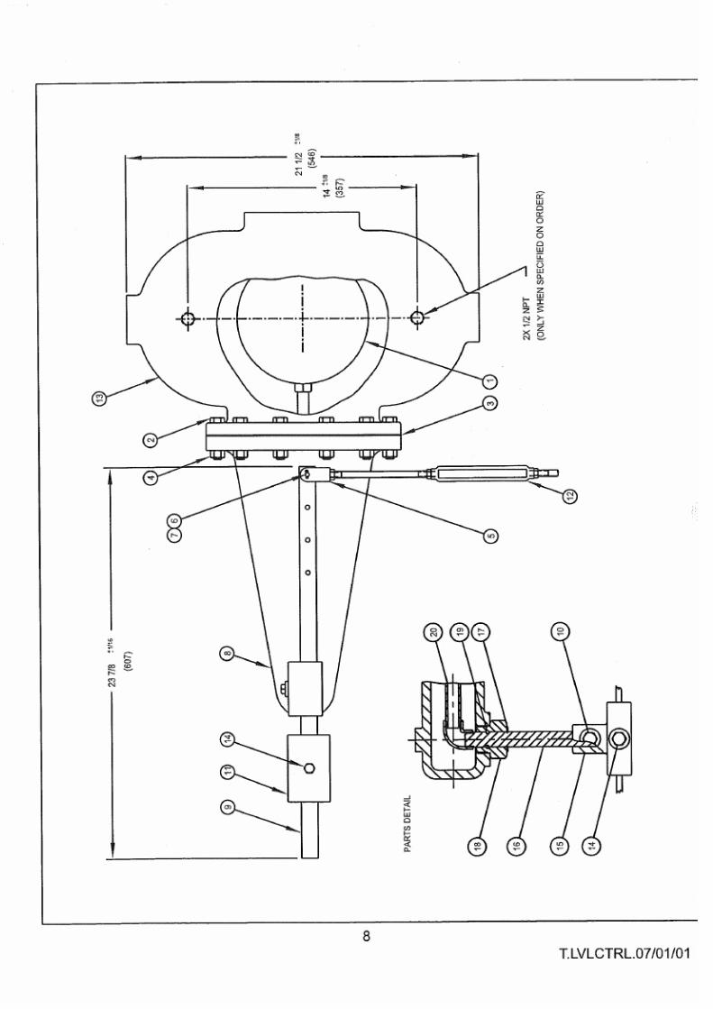
8/11/2019 Manual Caldera.pdf
http://slidepdf.com/reader/full/manual-calderapdf 768/838

8/11/2019 Manual Caldera.pdf
http://slidepdf.com/reader/full/manual-calderapdf 769/838

8/11/2019 Manual Caldera.pdf
http://slidepdf.com/reader/full/manual-calderapdf 770/838

8/11/2019 Manual Caldera.pdf
http://slidepdf.com/reader/full/manual-calderapdf 771/838

8/11/2019 Manual Caldera.pdf
http://slidepdf.com/reader/full/manual-calderapdf 772/838

8/11/2019 Manual Caldera.pdf
http://slidepdf.com/reader/full/manual-calderapdf 773/838

8/11/2019 Manual Caldera.pdf
http://slidepdf.com/reader/full/manual-calderapdf 774/838

8/11/2019 Manual Caldera.pdf
http://slidepdf.com/reader/full/manual-calderapdf 775/838

8/11/2019 Manual Caldera.pdf
http://slidepdf.com/reader/full/manual-calderapdf 776/838

8/11/2019 Manual Caldera.pdf
http://slidepdf.com/reader/full/manual-calderapdf 777/838

8/11/2019 Manual Caldera.pdf
http://slidepdf.com/reader/full/manual-calderapdf 778/838

8/11/2019 Manual Caldera.pdf
http://slidepdf.com/reader/full/manual-calderapdf 779/838

8/11/2019 Manual Caldera.pdf
http://slidepdf.com/reader/full/manual-calderapdf 780/838

8/11/2019 Manual Caldera.pdf
http://slidepdf.com/reader/full/manual-calderapdf 781/838

8/11/2019 Manual Caldera.pdf
http://slidepdf.com/reader/full/manual-calderapdf 782/838

8/11/2019 Manual Caldera.pdf
http://slidepdf.com/reader/full/manual-calderapdf 783/838

8/11/2019 Manual Caldera.pdf
http://slidepdf.com/reader/full/manual-calderapdf 784/838

8/11/2019 Manual Caldera.pdf
http://slidepdf.com/reader/full/manual-calderapdf 785/838

8/11/2019 Manual Caldera.pdf
http://slidepdf.com/reader/full/manual-calderapdf 786/838

8/11/2019 Manual Caldera.pdf
http://slidepdf.com/reader/full/manual-calderapdf 787/838

8/11/2019 Manual Caldera.pdf
http://slidepdf.com/reader/full/manual-calderapdf 788/838

8/11/2019 Manual Caldera.pdf
http://slidepdf.com/reader/full/manual-calderapdf 789/838

8/11/2019 Manual Caldera.pdf
http://slidepdf.com/reader/full/manual-calderapdf 790/838

8/11/2019 Manual Caldera.pdf
http://slidepdf.com/reader/full/manual-calderapdf 791/838

8/11/2019 Manual Caldera.pdf
http://slidepdf.com/reader/full/manual-calderapdf 792/838

8/11/2019 Manual Caldera.pdf
http://slidepdf.com/reader/full/manual-calderapdf 793/838

8/11/2019 Manual Caldera.pdf
http://slidepdf.com/reader/full/manual-calderapdf 794/838

8/11/2019 Manual Caldera.pdf
http://slidepdf.com/reader/full/manual-calderapdf 795/838

8/11/2019 Manual Caldera.pdf
http://slidepdf.com/reader/full/manual-calderapdf 796/838

8/11/2019 Manual Caldera.pdf
http://slidepdf.com/reader/full/manual-calderapdf 797/838

8/11/2019 Manual Caldera.pdf
http://slidepdf.com/reader/full/manual-calderapdf 798/838

8/11/2019 Manual Caldera.pdf
http://slidepdf.com/reader/full/manual-calderapdf 799/838

8/11/2019 Manual Caldera.pdf
http://slidepdf.com/reader/full/manual-calderapdf 800/838

8/11/2019 Manual Caldera.pdf
http://slidepdf.com/reader/full/manual-calderapdf 801/838

8/11/2019 Manual Caldera.pdf
http://slidepdf.com/reader/full/manual-calderapdf 802/838

8/11/2019 Manual Caldera.pdf
http://slidepdf.com/reader/full/manual-calderapdf 803/838

8/11/2019 Manual Caldera.pdf
http://slidepdf.com/reader/full/manual-calderapdf 804/838

8/11/2019 Manual Caldera.pdf
http://slidepdf.com/reader/full/manual-calderapdf 805/838

8/11/2019 Manual Caldera.pdf
http://slidepdf.com/reader/full/manual-calderapdf 806/838

8/11/2019 Manual Caldera.pdf
http://slidepdf.com/reader/full/manual-calderapdf 807/838

8/11/2019 Manual Caldera.pdf
http://slidepdf.com/reader/full/manual-calderapdf 808/838

8/11/2019 Manual Caldera.pdf
http://slidepdf.com/reader/full/manual-calderapdf 809/838

8/11/2019 Manual Caldera.pdf
http://slidepdf.com/reader/full/manual-calderapdf 810/838

8/11/2019 Manual Caldera.pdf
http://slidepdf.com/reader/full/manual-calderapdf 811/838

8/11/2019 Manual Caldera.pdf
http://slidepdf.com/reader/full/manual-calderapdf 812/838

8/11/2019 Manual Caldera.pdf
http://slidepdf.com/reader/full/manual-calderapdf 813/838

8/11/2019 Manual Caldera.pdf
http://slidepdf.com/reader/full/manual-calderapdf 814/838

8/11/2019 Manual Caldera.pdf
http://slidepdf.com/reader/full/manual-calderapdf 815/838

8/11/2019 Manual Caldera.pdf
http://slidepdf.com/reader/full/manual-calderapdf 816/838

8/11/2019 Manual Caldera.pdf
http://slidepdf.com/reader/full/manual-calderapdf 817/838

8/11/2019 Manual Caldera.pdf
http://slidepdf.com/reader/full/manual-calderapdf 818/838

8/11/2019 Manual Caldera.pdf
http://slidepdf.com/reader/full/manual-calderapdf 819/838

8/11/2019 Manual Caldera.pdf
http://slidepdf.com/reader/full/manual-calderapdf 820/838

8/11/2019 Manual Caldera.pdf
http://slidepdf.com/reader/full/manual-calderapdf 821/838

8/11/2019 Manual Caldera.pdf
http://slidepdf.com/reader/full/manual-calderapdf 822/838

8/11/2019 Manual Caldera.pdf
http://slidepdf.com/reader/full/manual-calderapdf 823/838

8/11/2019 Manual Caldera.pdf
http://slidepdf.com/reader/full/manual-calderapdf 824/838

8/11/2019 Manual Caldera.pdf
http://slidepdf.com/reader/full/manual-calderapdf 825/838

8/11/2019 Manual Caldera.pdf
http://slidepdf.com/reader/full/manual-calderapdf 826/838

8/11/2019 Manual Caldera.pdf
http://slidepdf.com/reader/full/manual-calderapdf 827/838

8/11/2019 Manual Caldera.pdf
http://slidepdf.com/reader/full/manual-calderapdf 828/838

8/11/2019 Manual Caldera.pdf
http://slidepdf.com/reader/full/manual-calderapdf 829/838

8/11/2019 Manual Caldera.pdf
http://slidepdf.com/reader/full/manual-calderapdf 830/838

8/11/2019 Manual Caldera.pdf
http://slidepdf.com/reader/full/manual-calderapdf 831/838

8/11/2019 Manual Caldera.pdf
http://slidepdf.com/reader/full/manual-calderapdf 832/838

8/11/2019 Manual Caldera.pdf
http://slidepdf.com/reader/full/manual-calderapdf 833/838

8/11/2019 Manual Caldera.pdf
http://slidepdf.com/reader/full/manual-calderapdf 834/838

8/11/2019 Manual Caldera.pdf
http://slidepdf.com/reader/full/manual-calderapdf 835/838

8/11/2019 Manual Caldera.pdf
http://slidepdf.com/reader/full/manual-calderapdf 836/838

8/11/2019 Manual Caldera.pdf
http://slidepdf.com/reader/full/manual-calderapdf 837/838

8/11/2019 Manual Caldera.pdf
http://slidepdf.com/reader/full/manual-calderapdf 838/838